fcc radio test report no.: tb-fcc152355 page: 6 of 33 tb-rf-074-1.1 1.8 test facility the testing...
TRANSCRIPT

Shenzhen Toby Technology Co., Ltd.
Report No.: TB-FCC152355
Page: 1 of 33
TB-RF-074-1.0
1A/F., Bldg.6, Yusheng Industrial Zone, The National Road No.107 Xixiang Section 467, Xixiang, Bao’an, Shenzhen, China
Tel: +86 75526509301 Fax: +86 75526509195
FCC Radio Test Report
FCC ID: 2ALXO-D8R
Report No. : TB-FCC152355
Applicant : Dong Yang Smart Technology Co.,Ltd
Equipment Under Test (EUT)
EUT Name : Wireless Remote Control
Model No. : D8R
Serial Model No. : N/A
Brand Name : DYS
Receipt Date : 2017-04-05
Test Date : 2017-04-06 to 2017-04-27
Issue Date : 2017-04-28
Standards : FCC Part 15, Subpart C (15.249: 2016)
Test Method : ANSI C63.10: 2013
Conclusions : PASS
In the configuration tested, the EUT complied with the standards specified above,
The EUT technically complies with the FCC requirements
Test/Witness Engineer :
Approved& Authorized :
This report details the results of the testing carried out on one sample. The results contained in
this test report do not relate to other samples of the same product. The manufacturer should
ensure that all products in series production are in conformity with the product sample detailed in
the report.

Report No.: TB-FCC152355
Page: 2 of 33
TB-RF-074-1.1
Contents
CONTENTS ............................................................................................................................................. 2
1. GENERAL INFORMATION ABOUT EUT ............................................................................. 3
1.1 Client Information ................................................................................................................. 3 1.2 General Description of EUT (Equipment Under Test) ................................................... 3 1.3 Block Diagram Showing the Configuration of System Tested ...................................... 4 1.4 Description of Support Units .............................................................................................. 4 1.5 Description of Test Mode .................................................................................................... 4 1.6 Description of Test Software Setting ................................................................................ 5 1.7 Measurement Uncertainty .................................................................................................. 5 1.8 Test Facility ........................................................................................................................... 6
2. TEST SUMMARY ....................................................................................................................... 7
3. TEST EQUIPMENT .................................................................................................................... 8
4. CONDUCTED EMISSION TEST ............................................................................................. 9
4.1 Test Standard and Limit ...................................................................................................... 9 4.2 Test Setup ............................................................................................................................. 9 4.3 Test Procedure ..................................................................................................................... 9 4.4 EUT Operating Mode ........................................................................................................ 10 4.5 Test Data ............................................................................................................................. 10
5. RADIATED EMISSION TEST ................................................................................................ 11
5.1 Test Standard and Limit .................................................................................................... 11 5.2 Test Setup ........................................................................................................................... 12 5.3 Test Procedure ................................................................................................................... 13 5.4 EUT Operating Condition ................................................................................................. 14 5.5 Test Data ............................................................................................................................. 14
6. BANDWIDTH TEST ................................................................................................................. 29
6.1 Test Setup ........................................................................................................................... 29 6.2 Test Procedure ................................................................................................................... 29 6.3 EUT Operating Condition ................................................................................................. 29 6.4 Test Data ............................................................................................................................. 29
7. ANTENNA REQUIREMENT ................................................................................................... 33
7.1 Standard Requirement ...................................................................................................... 33 7.2 Antenna Connected Construction ................................................................................... 33 7.3 Result ................................................................................................................................... 33

Report No.: TB-FCC152355
Page: 3 of 33
TB-RF-074-1.1
1. General Information about EUT
1.1 Client Information
Applicant : Dong Yang Smart Technology Co.,Ltd
Address : No.45, FuDong Industrial Zone, HeChang Rd 2, ZhongKai High Tech
Zone, Huizhou City, Guangdong Province, China
Manufacturer : Dong Yang Smart Technology Co.,Ltd
Address : No.45, FuDong Industrial Zone, HeChang Rd 2, ZhongKai High Tech
Zone, Huizhou City, Guangdong Province, China
1.2 General Description of EUT (Equipment Under Test)
EUT Name : Wireless Remote Control
Models No. : D8R
Model
Difference
: N/A
Product
Description :
Operation Frequency: 2405~2479 MHz
Number of Channels: 9 Channels(See Note 2)
Out Power: 96.35 dBuV/m@3m Peak
91.89 dBuV/m@3m Avg
Antenna Gain: 0 dBi Integral Antenna
Modulation Type: GFSK
Power Supply : DC power by AA battery.
Power Rating : DC 4*1.5V by AA Battery
Connecting I/O
Port(S)
: Please refer to the User's Manual
Note:
(1) For a more detailed features description, please refer to the manufacturer’s specifications or
the User’s Manual.
(2) Channel List:
Channel List
Channel Frequency
(MHz) Channel
Frequency
(MHz) Channel
Frequency
(MHz)
01 2405 04 2432 07 2460
02 2414 05 2442 08 2470
03 2423 06 2450 09 2479

Report No.: TB-FCC152355
Page: 4 of 33
TB-RF-074-1.1
1.3 Block Diagram Showing the Configuration of System Tested
1.4 Description of Support Units
The EUT has been test as an independent unit.
1.5 Description of Test Mode
To investigate the maximum EMI emission characteristics generates from EUT, the test
system was pre-scanning tested base on the consideration of following EUT operation mode
or test configuration mode which possible have effect on EMI emission level. Each of these
EUT operation mode(s) or test configuration mode(s) mentioned follow was evaluated
respectively.
For Conducted Test
Final Test Mode Description
Mode 1 N/A
For Radiated Test
Final Test Mode Description
Mode 2 TX Mode(CH01/CH05/CH09)
Note:
For all test, we have verified the construction and function in typical operation. And all the
test modes were carried out with the EUT in transmitting operation in maximum power with
all kinds of data rate.
(1)According to ANSI C63.10 standards, the measurements are performed at the highest,
middle, lowest available channels.
(2)During the testing procedure, the continuously transmitting with the maximum power
mode was programmed by the customer.
EUT
TX Mode

Report No.: TB-FCC152355
Page: 5 of 33
TB-RF-074-1.1
(3) The EUT is considered a portable unit; it was pre-tested on the positioned of each 3 axis,
X-plane, Y-plane and Z-plane. The worst case was found positioned on X-plane.
Therefore only the test data of this X-plane was used for radiated emission measurement
test.
1.6 Description of Test Software Setting
During testing channel & Power controlling software provided by the customer was used to
control the operating channel as well as the output power level. The RF output power
selection is for the setting of RF output power expected by the customer and is going to be
fixed on the firmware of the final end product power parameters of RF mode.
Product SW/HW
Version : N/A
Radio SW/HW Version: N/A
Test Software Version N/A
Frequency 2405 MHz 2442MHz 2479 MHz
GFSK DEF DEF DEF
1.7 Measurement Uncertainty
The reported uncertainty of measurement y ± U,where expended uncertainty U is based on
a standard uncertainty multiplied by a coverage factor of k=2,providing a level of
confidence of approximately 95 %.
Test Item Parameters Expanded Uncertainty (ULab)
Conducted Emission
Level Accuracy:
9kHz~150kHz
150kHz to 30MHz
±3.42 dB
±3.42 dB
Radiated Emission Level Accuracy:
9kHz to 30 MHz ±4.60 dB
Radiated Emission Level Accuracy:
30MHz to 1000 MHz ±4.40 dB
Radiated Emission Level Accuracy:
Above 1000MHz ±4.20 dB

Report No.: TB-FCC152355
Page: 6 of 33
TB-RF-074-1.1
1.8 Test Facility
The testing report were performed by the Shenzhen Toby Technology Co., Ltd., in their
facilities located at 1A/F., Bldg.6, Yusheng Industrial Zone, The National Road No.107
Xixiang Section 467, Xixiang, Bao’an, Shenzhen, Guangdong, China. At the time of testing,
the following bodies accredited the Laboratory:
CNAS (L5813)
The Laboratory has been accredited by CNAS to ISO/IEC 17025: 2005 General
Requirements for the Competence of Testing and Calibration Laboratories for the
competence in the field of testing. And the Registration No.: CNAS L5813.
FCC List No.: (811562)
The Laboratory is listed in the United States of American Federal Communications
Commission (FCC), and the registration number is 811562.
IC Registration No.: (11950A-1)
The Laboratory has been registered by Certification and Engineering Bureau of Industry
Canada for radio equipment testing. The site registration: Site# 11950A-1.

Report No.: TB-FCC152355
Page: 7 of 33
TB-RF-074-1.1
2. Test Summary
FCC Part 15 Subpart C(15.249)
Standard Section Test Item Judgment Remark
15.203 Antenna Requirement PASS N/A
15.205 Restricted Bands PASS N/A
15.207 AC Power Conducted
Emission N/A N/A
15.249 &15.209 Radiated Spurious Emission PASS N/A
15.215(C) 20dB Bandwidth PASS N/A
Note: N/A is an abbreviation for Not Applicable.

Report No.: TB-FCC152355
Page: 8 of 33
TB-RF-074-1.1
3. Test Equipment
Conducted Emission Test
Equipment Manufacturer Model No. Serial No. Last Cal. Cal. Due
Date
EMI Test
Receiver Rohde & Schwarz ESCI 100321 Jul. 22, 2016 Jul. 21, 2017
RF Switching
Unit
Compliance
Direction Systems
Inc
RSU-A4 34403 Jul. 22, 2016 Jul. 21, 2017
AMN SCHWARZBECK NNBL 8226-2 8226-2/164 Jul. 22, 2016 Jul. 21, 2017
LISN Rohde & Schwarz ENV216 101131 Jul. 22, 2016 Jul. 21, 2017
Radiation Emission Test
Equipment Manufacturer Model No. Serial No. Last Cal. Cal. Due
Date
Spectrum
Analyzer Agilent E4407B MY45106456 Jul. 22, 2016 Jul. 21, 2017
EMI Test
Receiver Rohde & Schwarz ESPI 100010/007 Jul. 22, 2016 Jul. 21, 2017
Bilog Antenna ETS-LINDGREN 3142E 00117537 Mar. 25, 2017 Mar. 24, 2018
Bilog Antenna ETS-LINDGREN 3142E 00117542 Mar. 25, 2017 Mar. 24, 2018
Horn Antenna ETS-LINDGREN 3117 00143207 Mar. 25, 2017 Mar. 24, 2018
Horn Antenna ETS-LINDGREN 3117 00143209 Mar. 25, 2017 Mar. 24, 2018
Loop Antenna Laplace instrument RF300 0701 Mar. 25, 2017 Mar. 24, 2018
Pre-amplifier Sonoma 310N 185903 Mar. 24, 2017 Mar. 23, 2018
Pre-amplifier HP 8449B 3008A00849 Mar. 29, 2017 Mar. 28, 2018
Cable HUBER+SUHNER 100 SUCOFLEX Mar. 29, 2017 Mar. 28, 2018
Positioning
Controller ETS-LINDGREN 2090 N/A N/A N/A
Antenna Conducted Emission
Equipment Manufacturer Model No. Serial No. Last Cal. Cal. Due
Date
Spectrum
Analyzer Agilent E4407B MY45106456 Jul. 22, 2016 Jul. 21, 2017
Spectrum
Analyzer Rohde & Schwarz ESCI 100010/007 Jul. 22, 2016 Jul. 21, 2017
Power Meter Anritsu ML2495A 25406005 Jul. 22, 2016 Jul. 21, 2017
Power Sensor Anritsu ML2411B 25406005 Jul. 22, 2016 Jul. 21, 2017

Report No.: TB-FCC152355
Page: 9 of 33
TB-RF-074-1.1
4. Conducted Emission Test
4.1 Test Standard and Limit
4.1.1Test Standard
FCC Part 15.207
4.1.2 Test Limit
Conducted Emission Test Limit
Frequency Maximum RF Line Voltage (dBV)
Quasi-peak Level Average Level
150kHz~500kHz 66 ~ 56 * 56 ~ 46 *
500kHz~5MHz 56 46
5MHz~30MHz 60 50
Notes:
(1) *Decreasing linearly with logarithm of the frequency.
(2) The lower limit shall apply at the transition frequencies.
(3) The limit decrease in line with the logarithm of the frequency in the range of 0.15 to
0.50MHz.
4.2 Test Setup
4.3 Test Procedure
The EUT was placed 0.8 meters from the horizontal ground plane with EUT being
connected to the power mains through a line impedance stabilization network (LISN). All
other support equipments powered from additional LISN(s). The LISN provide 50 Ohm/
50uH of coupling impedance for the measuring instrument.
Interconnecting cables that hang closer than 40 cm to the ground plane shall be folded back
and forth in the center forming a bundle 30 to 40 cm long.

Report No.: TB-FCC152355
Page: 10 of 33
TB-RF-074-1.1
I/O cables that are not connected to a peripheral shall be bundled in the center. The end of
the cable may be terminated, if required, using the correct terminating impedance. The
overall length shall not exceed 1 m.
LISN is at least 80 cm from nearest part of EUT chassis.
The bandwidth of EMI test receiver is set at 9kHz, and the test frequency band is from
0.15MHz to 30MHz.
4.4 EUT Operating Mode
Please refer to the description of test mode.
4.5 Test Data
The EUT is powered by DC battery, no requirement for this test item.

Report No.: TB-FCC152355
Page: 11 of 33
TB-RF-074-1.1
5. Radiated Emission Test
5.1 Test Standard and Limit
5.1.1 Test Standard
FCC Part 15.209
5.1.2 Test Limit
Radiated Emission Limit (9kHz~1000MHz)
Frequency
(MHz
Field Strength
(microvolt/meter)
Measurement Distance
(meters)
0.009~0.490 2400/F(KHz) 300
0.490~1.705 24000/F(KHz) 30
1.705~30.0 30 30
30~88 100 3
88~216 150 3
216~960 200 3
Above 960 500 3
Radiated Emission Limit (Above 1000MHz)
Frequency
(MHz)
Distance Meters (at 3m)
Peak Average
Above 1000 74 54
Note:
(1) The tighter limit applies at the band edges.
(2) Emission Level(dBuV/m)=20log Emission Level(Uv/m)
Limits of radiated emission measurement (15.249)
FCC Part 15 (15.249), Subpart C
Limit Frequency Range (MHz)
Field strength of fundamental
50000 V/m (94 dBV/m) @ 3 m 2400~2483.5
Field strength of fundamental
500 V/m (94 dBV/m) @ 3 m Above 2483.5
Restricted bands requirement for equipment operating in 2400MHz to 2483.5 MHz
(15.249)

Report No.: TB-FCC152355
Page: 12 of 33
TB-RF-074-1.1
Restricted Frequency Band
(MHz)
(dBuV/m)(at 3 M)
2310~2390 Attenuated by at least 50 dB below the level
of the fundamental or to the general radiated
emission limits in 15.209, whichever is the
lesser attenuation 2483.5~2500
5.2 Test Setup
Bellow 30MHz Test Setup
Bellow 1000MHz Test Setup

Report No.: TB-FCC152355
Page: 13 of 33
TB-RF-074-1.1
Above 1GHz Test Setup
5.3 Test Procedure
(1) The measuring distance of 3m shall be used for measurements at frequency up to 1GHz and
above 1 GHz. The EUT was placed on a rotating 0.8m high above ground, the table was
rotated 360 degrees to determine the position of the highest radiation.
(2) Measurements at frequency above 1GHz. The EUT was placed on a rotating 1.5m high
above the ground. RF absorbers covered the ground plane with a minimum area of 3.0m by
3.0m between the EUT and measurement receiver antenna. The RF absorber shall not
exceed 30cm in high above the conducting floor. The table was rotated 360 degrees to
determine the position of the highest radiation.
(3) The Test antenna shall vary between 1m and 4m, Both Horizontal and Vertical antenna are
set to make measurement.
(4) The initial step in collecting conducted emission data is a spectrum analyzer peak detector
mode pre-scanning the measurement frequency range. Significant peaks are then marked
and then Quasi Peak detector mode re-measured.
(5) If the Peak Mode measured value compliance with and lower than Quasi Peak Mode Limit
Bellow 1 GHz, the EUT shall be deemed to meet QP Limits and then no additional QP Mode
measurement performed. But the Peak Value and average value both need to comply with
applicable limit above 1 GHz.
(6) Testing frequency range below 1GHz the measuring instrument use VBW=120 kHz with
Quasi-peak detection.
(7) Testing frequency range above 1GHz the measuring instrument use RBW=1 MHz and
VBW=3 MHz with Peak Detector for Peak Values, and use RBW=1 MHz and VBW=10 Hz
with Peak Detector for Average Values.
(8) For the actual test configuration, please see the test setup photo.

Report No.: TB-FCC152355
Page: 14 of 33
TB-RF-074-1.1
5.4 EUT Operating Condition
The EUT was set to Continual Transmitting in maximum power, and new batteries are used
during testing.
5.5 Test Data
Please see the next page.

Report No.: TB-FCC152355
Page: 15 of 33
TB-RF-074-1.1
5.6.1 Field Strength of the Fundamental
EUT: Wireless Remote Control Model Name : D8R
Temperature: 25 ℃ Relative Humidity: 55%
Test Voltage: DC 6V
Ant. Pol. Horizontal
Test Mode: TX 2405MHz
Remark:
Emission Level= Read Level+ Correct Factor
114.00 -19.64
94.00 -8.07

Report No.: TB-FCC152355
Page: 16 of 33
TB-RF-074-1.1
EUT: Wireless Remote Control Model Name : D8R
Temperature: 25 ℃ Relative Humidity: 55%
Test Voltage: DC 6V
Ant. Pol. Vertical
Test Mode: TX 2405MHz
Remark:
Emission Level= Read Level+ Correct Factor
94.00 -8.24
114.00 -21.33

Report No.: TB-FCC152355
Page: 17 of 33
TB-RF-074-1.1
EUT: Wireless Remote Control Model Name : D8R
Temperature: 25 ℃ Relative Humidity: 55%
Test Voltage: DC 6V
Ant. Pol. Horizontal
Test Mode: TX 2442MHz
Remark:
Emission Level= Read Level+ Correct Factor
114.00 -20.75
94.00 -11.65

Report No.: TB-FCC152355
Page: 18 of 33
TB-RF-074-1.1
EUT: Wireless Remote Control Model Name : D8R
Temperature: 25 ℃ Relative Humidity: 55%
Test Voltage: DC 6V
Ant. Pol. Vertical
Test Mode: TX 2442MHz
Remark:
Emission Level= Read Level+ Correct Factor
114.00 -17.65
94.00 -6.32

Report No.: TB-FCC152355
Page: 19 of 33
TB-RF-074-1.1
EUT: Wireless Remote Control Model Name : D8R
Temperature: 25 ℃ Relative Humidity: 55%
Test Voltage: DC 6V
Ant. Pol. Horizontal
Test Mode: TX 2479MHz
Remark:
Emission Level= Read Level+ Correct Factor
94.00 -4.27
114.00 -18.64

Report No.: TB-FCC152355
Page: 20 of 33
TB-RF-074-1.1
EUT: Wireless Remote Control Model Name : D8R
Temperature: 25 ℃ Relative Humidity: 55%
Test Voltage: DC 6V
Ant. Pol. Vertical
Test Mode: TX 2479MHz
Remark:
Emission Level= Read Level+ Correct Factor
114.00 -18.38
94.00 -2.11

Report No.: TB-FCC152355
Page: 21 of 33
TB-RF-074-1.1
5.6.2 Radiated Spurious Emission (9 KHz~30 MHz)
From 9 KHz to 30 MHz: Conclusion: PASS
Note: The amplitude of spurious emissions which are attenuated by more than 20dB
below the permissible value has no need to be reported.
5.6.3 Radiated Spurious Emission (Below 1 GHz)
EUT: Wireless Remote Control Model Name : D8R
Temperature: 25 ℃ Relative Humidity: 55%
Test Voltage: DC 6V
Ant. Pol. Horizontal
Test Mode: TX 2405MHz
Remark: Only worse case is reported
Emission Level= Read Level+ Correct Factor

Report No.: TB-FCC152355
Page: 22 of 33
TB-RF-074-1.1
EUT: Wireless Remote Control Model Name : D8R
Temperature: 25 ℃ Relative Humidity: 55%
Test Voltage: DC 6V
Ant. Pol. Vertical
Test Mode: TX 2405MHz
Remark: Only worse case is reported
Emission Level= Read Level+ Correct Factor

Report No.: TB-FCC152355
Page: 23 of 33
TB-RF-074-1.1
5.6.4 Radiated Spurious Emission (Above 1 GHz)
EUT: Wireless Remote Control Model Name : D8R
Temperature: 25 ℃ Relative Humidity: 55%
Test Voltage: DC 6V
Ant. Pol. Horizontal
Test Mode: TX 2405MHz
Remark: No report for the emission which more than 10 dB below the
prescribed limit.
Emission Level= Read Level+ Correct Factor

Report No.: TB-FCC152355
Page: 24 of 33
TB-RF-074-1.1
EUT: Wireless Remote Control Model Name : D8R
Temperature: 25 ℃ Relative Humidity: 55%
Test Voltage: DC 6V
Ant. Pol. Vertical
Test Mode: TX 2405MHz
Remark: No report for the emission which more than 10 dB below the
prescribed limit.
Emission Level= Read Level+ Correct Factor

Report No.: TB-FCC152355
Page: 25 of 33
TB-RF-074-1.1
EUT: Wireless Remote Control Model Name : D8R
Temperature: 25 ℃ Relative Humidity: 55%
Test Voltage: DC 6V
Ant. Pol. Horizontal
Test Mode: TX 2442MHz
Remark: No report for the emission which more than 10 dB below the
prescribed limit.
Emission Level= Read Level+ Correct Factor

Report No.: TB-FCC152355
Page: 26 of 33
TB-RF-074-1.1
EUT: Wireless Remote Control Model Name : D8R
Temperature: 25 ℃ Relative Humidity: 55%
Test Voltage: DC 6V
Ant. Pol. Vertical
Test Mode: TX 2442MHz
Remark: No report for the emission which more than 10 dB below the
prescribed limit.
Emission Level= Read Level+ Correct Factor

Report No.: TB-FCC152355
Page: 27 of 33
TB-RF-074-1.1
EUT: Wireless Remote Control Model Name : D8R
Temperature: 25 ℃ Relative Humidity: 55%
Test Voltage: DC 6V
Ant. Pol. Horizontal
Test Mode: TX 2479MHz
Remark: No report for the emission which more than 10 dB below the
prescribed limit.
Emission Level= Read Level+ Correct Factor

Report No.: TB-FCC152355
Page: 28 of 33
TB-RF-074-1.1
EUT: Wireless Remote Control Model Name : D8R
Temperature: 25 ℃ Relative Humidity: 55%
Test Voltage: DC 6V
Ant. Pol. Vertical
Test Mode: TX 2479MHz
Remark: No report for the emission which more than 10 dB below the
prescribed limit.
Emission Level= Read Level+ Correct Factor

Report No.: TB-FCC152355
Page: 29 of 33
TB-RF-074-1.1
6. Bandwidth Test
6.1 Test Setup
6.2 Test Procedure
(1) The EUT was directly connected to the spectrum analyzer and antenna output port as show
in the block diagram above.
(2) Spectrum Setting:
Bandwidth: RBW=100 kHz, VBW=300kHz.
(3) The bandwidth is measured at an amplitude level reduced 20dB from the reference level. The
reference level is the level of the highest amplitude signal observed from the transmitter at
the fundamental frequency. Once the reference level is established, the equipment is
conditioned with typical modulating signal to produce the worst –case (i.e the widest)
bandwidth.
6.3 EUT Operating Condition
The EUT was set to continuously transmitting for the Bandwidth Test.
6.4 Test Data

Report No.: TB-FCC152355
Page: 30 of 33
TB-RF-074-1.1
Low Channel Frequency (MHz) 20dB Bandwidth (KHz)
2405 606.004
2405 MHz
23:14:08 Apr 25, 2017
Ref 25 dBm Atten 35 dB#Peak
Log
10
dB/
Offst1dB
Center 2.405 GHz
#Res BW 100 kHz #VBW 300 kHz
Span 3 MHz
Sweep 5 ms (401 pts)
Span3.000000000 MHz
Occupied Bandwidth
Transmit Freq Error
Occ BW % Pwr
x dB Bandwidth
x dB828.7858 kHz
-235.678 kHz
99.00 %
606.004 kHz
-20.00 dB

Report No.: TB-FCC152355
Page: 31 of 33
TB-RF-074-1.1
MID Channel Frequency (MHz) 20dB Bandwidth (KHz)
2442 582.479
2442 MHz
Report No.: TB-FCC152355
Page: 32 of 33
TB-RF-074-1.1
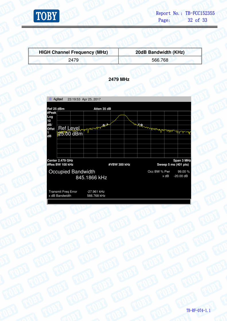
HIGH Channel Frequency (MHz) 20dB Bandwidth (KHz)
2479 566.768
2479 MHz
23:19:53 Apr 25, 2017
Ref 25 dBm Atten 35 dB#Peak
Log
10
dB/
Offst1dB
Center 2.479 GHz
#Res BW 100 kHz #VBW 300 kHz
Span 3 MHz
Sweep 5 ms (401 pts)
Ref Level25.00 dBm
Occupied Bandwidth
Transmit Freq Error
Occ BW % Pwr
x dB Bandwidth
x dB845.1866 kHz
-27.961 kHz
99.00 %
566.768 kHz
-20.00 dB

Report No.: TB-FCC152355
Page: 33 of 33
TB-RF-074-1.1
7. Antenna Requirement
7.1 Standard Requirement
7.1.1 Standard
FCC Part 15.203
7.1.2 Requirement
An intentional radiator shall be designed to ensure that no antenna other than that
furnished by the responsible party shall be used with the device. The use of a
permanently attached antenna or of an antenna that uses a unique coupling to the
intentional radiator shall be considered sufficient to comply with the provisions of this
Section. The manufacturer may design the unit so that a broken antenna can be
replaced by the user, but the use of a standard antenna jack or electrical connector is
prohibited.
7.2 Antenna Connected Construction
The directional gains of the antenna used for transmitting is 0 dBi, and the antenna
de-signed with permanent attachment and no consideration of replacement. Please see
the EUT photo for details.
7.3 Result
The EUT antenna is a Integral Antenna. It complies with the standard requirement.
Antenna Type
Permanent attached antenna
Unique connector antenna
Professional installation antenna
-----END OF REPORT----