fcc information - nedis
TRANSCRIPT


FCC InformationFEDERAL COMMUNICATIONS COMMISSION INTERFERENCE STATEMENT: This equipment has been tested and found to comply with the limits for a Class B digital service, pursuant to Part 15 of the FCC rules. These limits are designed to provide reasonable protection against harmful interference in a residential installation. Any changes or modifications made to this equipment may void the user’s authority to operate this equipment. This equipment generates, uses, and can radiate radio frequency energy. If not installed and used in accordance with the instructions, may cause harmful interference to radio communications. However, there is no guarantee that interference will not occur in a particular installation. If this equipment does cause harmful interference to radio or television reception, which can be determined by turning the equipment off and on, the user is encouraged to try to correct the interference by one or more of the following measures: Reorient or relocate the receiving antenna. Increase the separation between the equipment and receiver. Connect the equipment into an outlet on a circuit different from
that to which the receiver is connected. Consult the dealer or an experienced radio/TV technician for help.FCC Caution: Any changes or modifications not expressly approved by the party responsible for compliance could void the user's authority to operate this equipment.This device complies with Part 15 of the FCC Rules. Operation is subject to the following two conditions: (1) this device may not cause harmful interference, and (2) this device must accept any interference received, including interference that may cause undesired operation.
KCC Statement
RoHSThis product is RoHS compliant.
- 2 -

IC-485SN User ManualOnline RegistrationYou can register your product at our online support center:
Online Support
International
North America
International http://support.aten.com
Email Support [email protected]
Online Support
Technical Support http://support.aten.com
TroubleshootingDocumentationSoftware Updates
http://www.aten.com
Email Support [email protected]
Online Technical Support
TroubleshootingDocumentationSoftware Updates
http://www.aten-usa.com/support
Telephone Support 1-888-999-ATEN ext 49881-949-428-1111
- 3 -

Telephone SupportFor telephone support, call this number:
International 886-2-8692-6959
China 86-400-810-0-810
Japan 81-3-5615-5811
Korea 82-2-467-6789
North America 1-888-999-ATEN ext 49881-949-428-1111
- 4 -

Package Contents
The IC-485SN package contains the following items:
1 IC-485SN Bidirectional Converter 1 User Manual
Check to make sure that all the components are present and that nothing got damaged in shipping. If you encounter a problem, contact your dealer.
Read this manual thoroughly and follow the installation and operation procedures carefully to prevent any damage to the unit, and/or any of the devices connected to it.
* Features may have been added to the IC-485SN since this manual was printed. Please visit our website to download the most up-to-date version of the manual.
Copyright © 1998-2020 ATEN® International Co., Ltd.Manual Part No. PAPE-1134-101G
Manual Date: 2020-12-04
ATEN and the ATEN logo are trademarks of ATEN International Co., Ltd. All rightsreserved. All other trademarks are the property of their respective owners.
- 5 -

Overview
Although RS-232 serial ports are found on almost every computer, because of their slow transmission speeds, limited range, and limited networking capabilities, they are not an effective solution for industrial strength long distance communications systems.
Systems based on the RS-422 and RS-485 standards, on the other hand, are not subject to the RS-232 limitations because they utilize different voltage lines for the data and control signals.
The IC-485SN Converter is a bidirectional converter that transparently converts RS-232 signals to RS-422 / RS-485 signals (and vice versa). The IC-485SN provides Point-to-Point; Multidrop; and Simplex operations over distances of up to 1200 m (4000 ft.), thus permitting the creation of reliable long distance data communications systems using standard computer hardware.
Features
Data Transmission Controlled by the RTS Signal DCE / DTE selectable Point to Point/Multidrop and Simplex/Duplex Operating
Modes External Power Not Required - Power Spplied by the RS-232
interface Compact size
- 6 -

Switch Configuration
The IC-485SN is configured by setting two slide switches. SW1 is used to select the Device Mode; SW2 is used to select the Transmitting and Receiving Mode, as shown in the table below:
Position SW1 SW2
1 DCE TxON, RxON
2 DTE TxRTS, RxON
3 TxDTR/RTS, RxDSR/ON
RS-232CRS-232CDB-25 FemaleDB-25 Female
Terminal BlockTerminal Block
SW1SW1SW2SW2
RJ-11 Phone JackRJ-11 Phone Jack
Power JackPower Jack
ConnecterConnecter
ConnecterConnecter
- 7 -
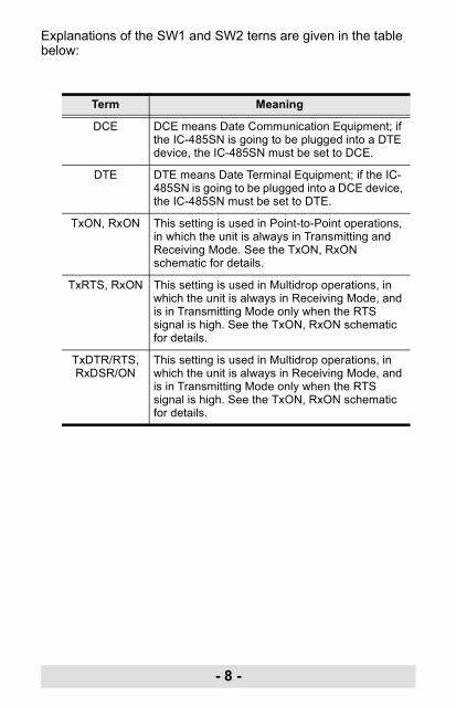
Explanations of the SW1 and SW2 terns are given in the table below:
Term Meaning
DCE DCE means Date Communication Equipment; if the IC-485SN is going to be plugged into a DTE device, the IC-485SN must be set to DCE.
DTE DTE means Date Terminal Equipment; if the IC-485SN is going to be plugged into a DCE device, the IC-485SN must be set to DTE.
TxON, RxON This setting is used in Point-to-Point operations, in which the unit is always in Transmitting and Receiving Mode. See the TxON, RxON schematic for details.
TxRTS, RxON This setting is used in Multidrop operations, in which the unit is always in Receiving Mode, and is in Transmitting Mode only when the RTS signal is high. See the TxON, RxON schematic for details.
TxDTR/RTS, RxDSR/ON
This setting is used in Multidrop operations, in which the unit is always in Receiving Mode, and is in Transmitting Mode only when the RTS signal is high. See the TxON, RxON schematic for details.
- 8 -

Operating Modes
The IC-485SN supports three operating modes: Point-to-Point; Multidrop; and Simplex. Point-to-Point and Multidrop can be configured for Full or Half Duplex. Each of the operating modes is explained below.
Point-to-PointA Point-to-Point configuration is one in which two devices, located at two different places are linked for communication by a pair of IC-485SN units. There are two configurations: Point-to-Point Full Duplex, and Point-to-Point Half Duplex.
1. Point-to-Point 4 Wire Full Duplex
Point-to-Point Full Duplex uses reverse four wire cabling, as shown in the diagram below.
For both IC-485SN units, set SW1 to DCE or DTE depending on what type of device the IC-485SN will plug into (if it will plug into a DCE device, configure it for DTE, and vice versa).
For both IC-485SN units, set SW2 to TxON, RxON.
42
DB-25 DB-25RJ-11 RJ-11
Connectto PC#1’sCom Port
5
23
54
3
TX+TX-RX+RX-
TX+TX-RX+RX-
Connectto PC#1’sCom Port
- 9 -
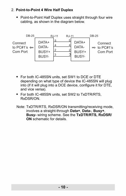
2. Point-to-Point 4 Wire Half Duplex
Point-to-Point Half Duplex uses straight through four wire cabling, as shown in the diagram below.
For both IC-485SN units, set SW1 to DCE or DTE depending on what type of device the IC-485SN will plug into (if it will plug into a DCE device, configure it for DTE, and vice versa).
For both IC-485SN units, set SW2 to TxDTR/RTS, RxDSR/ON.
Note: TxDTR/RTS, RxDSR/ON transmitting/receiving mode, involves a straight-through Data+, Data-, Busy+, Busy- wiring scheme. See the TxDTR/RTS, RxDSR/ON schematic for details.
42
DB-25 DB-25RJ-11 RJ-11
Connectto PC#1’sCom Port
5
23
54
3
DATA+DATA-BUSY+BUSY-
DATA+DATA-BUSY+BUSY-
Connectto PC#1’sCom Port
- 10 -
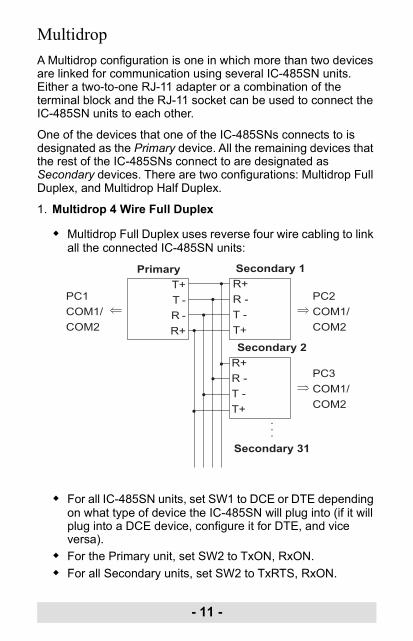
MultidropA Multidrop configuration is one in which more than two devices are linked for communication using several IC-485SN units. Either a two-to-one RJ-11 adapter or a combination of the terminal block and the RJ-11 socket can be used to connect the IC-485SN units to each other.
One of the devices that one of the IC-485SNs connects to is designated as the Primary device. All the remaining devices that the rest of the IC-485SNs connect to are designated as Secondary devices. There are two configurations: Multidrop Full Duplex, and Multidrop Half Duplex.
1. Multidrop 4 Wire Full Duplex
Multidrop Full Duplex uses reverse four wire cabling to link all the connected IC-485SN units:
For all IC-485SN units, set SW1 to DCE or DTE depending on what type of device the IC-485SN will plug into (if it will plug into a DCE device, configure it for DTE, and vice versa).
For the Primary unit, set SW2 to TxON, RxON. For all Secondary units, set SW2 to TxRTS, RxON.
PrimaryT+T -R -R+
Secondary 1R+R -T -T+Secondary 2
R+R -T -T+
...Secondary 31
PC1COM1/COM2
PC2COM1/COM2
PC3COM1/COM2
- 11 -
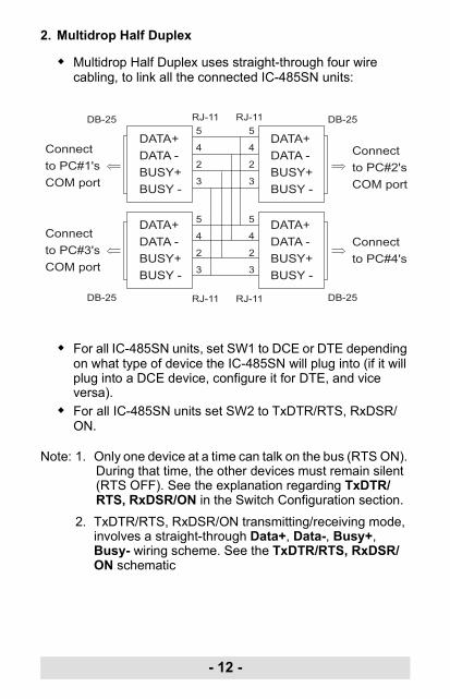
2. Multidrop Half Duplex
Multidrop Half Duplex uses straight-through four wire cabling, to link all the connected IC-485SN units:
For all IC-485SN units, set SW1 to DCE or DTE depending on what type of device the IC-485SN will plug into (if it will plug into a DCE device, configure it for DTE, and vice versa).
For all IC-485SN units set SW2 to TxDTR/RTS, RxDSR/ON.
Note: 1. Only one device at a time can talk on the bus (RTS ON). During that time, the other devices must remain silent (RTS OFF). See the explanation regarding TxDTR/RTS, RxDSR/ON in the Switch Configuration section.
2. TxDTR/RTS, RxDSR/ON transmitting/receiving mode, involves a straight-through Data+, Data-, Busy+, Busy- wiring scheme. See the TxDTR/RTS, RxDSR/ON schematic
DATA+DATA -BUSY+BUSY -
DATA+DATA -BUSY+BUSY -
DATA+DATA -BUSY+BUSY -
DATA+DATA -BUSY+BUSY -
Connectto PC#1'sCOM port
Connectto PC#2'sCOM port
Connectto PC#3'sCOM port
Connectto PC#4's
DB-25
RJ-11
RJ-11
RJ-11
RJ-11 DB-25
DB-25 DB-25
5
4
2
3
5
4
2
3
5
4
2
3
5
4
2
3
- 12 -
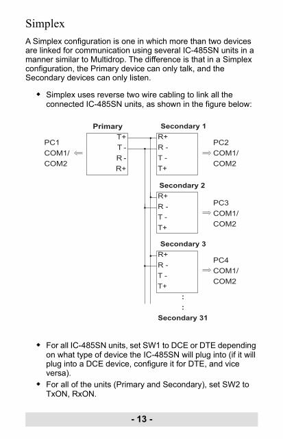
SimplexA Simplex configuration is one in which more than two devices are linked for communication using several IC-485SN units in a manner similar to Multidrop. The difference is that in a Simplex configuration, the Primary device can only talk, and the Secondary devices can only listen.
Simplex uses reverse two wire cabling to link all the connected IC-485SN units, as shown in the figure below:
For all IC-485SN units, set SW1 to DCE or DTE depending on what type of device the IC-485SN will plug into (if it will plug into a DCE device, configure it for DTE, and vice versa).
For all of the units (Primary and Secondary), set SW2 to TxON, RxON.
PrimaryT+T -R -R+
Secondary 1R+R -T -T+
Secondary 2R+R -T -T+
Secondary 3R+R -T -T+
::
Secondary 31
PC1COM1/COM2
PC2COM1/COM2
PC3COM1/COM2
PC4COM1/COM2
- 13 -

Installation
1. Set each IC-485SN's configuration switches according to the information provided in the Switch Configuration and Operating Modes sections.
2. Plug the IC-485SN's DB-25 female connector into the computer's RS-232C port.
3. Connect the IC-485SN units to each other: Use two or four wire twisted pair cable in a reverse or
straight through configuration according to the information provided in the Switch Configuration and Operating Modes sections.
You may use either the RJ-11 telephone socket, or wire directly to the Terminal Block. (See the Terminal Block Pin Assignments table for pin assigment details.) If you are daisy chaining units, you will need to use either a two-to-one RJ-11 adapter, or a combination of the Terminal Block and the RJ-11 socket.
Note: 1. When tightening the terminal connector screws it is recommended to use a Phillips PH1 Screwdriver.
2. Over-tightening the terminal connector screws may result in damage to your IC-485SN and difficulty loosening the screws.
4. Power on the computers. The units are now ready for operation.
- 14 -
Appendix
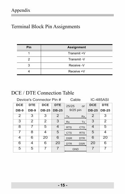
Terminal Block Pin Assignments
DCE / DTE Connection Table
Pin Assignment
1 Transmit +V
2 Transmit -V
3 Receive -V
4 Receive +V
DCE
DB-9
2387465
DTE
DB-9
3278645
DCE
DB-25
3254
2067
DTE
DB-25
23456
207
DCE
DB-25
23456
207
DTE
DB-25
3254
2067
Tx Rx
Rx Tx
RTS CTS
CTS RTS
DSR DTR
DTR DSR
GND
Cable
25/25 or9/25 pin
IC-485ASIDevice's Connector Pin #
- 15 -
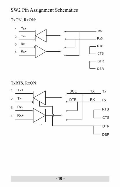
SW2 Pin Assignment Schematics
TxON, RxON:
TxRTS, RxON:
1
2
3
4
Tx+
Tx-
Rx-
Rx+
Tx2
Rx3
RTS
CTS
DTR
DSR
1
2
3
4
Tx+
Tx-
Rx-
Rx+
Tx
Rx
RTS
CTS
DTR
DSR
TX
RX
DCE
DTE
- 16 -

TxDTR/RTS, RxDSR/ON:
1
2
DATA +
DATA -
RTS
CTS
DTR
TX
RX
DCE
DTE
DCE
DTE
3
4
BUSY -
BUST +- DSR
- 17 -

Troubleshooting
Specifications
Symptom Action
Data Transmission Failure
Check that the IC-485SN units are securely plugged into the computers' serial ports.
Check that the cables are properly set up and properly connected.
Check that SW1 and SW2 are set properly.
Data Loss or Error Check that the Data Rate and Data Format are the same for all devices.
Power Consumption 6.51 mA
Data Rate Up to 100 Kbps under 1.2 Km (4000 ft.)
Connectors • 1 x DB-25 female (for RS-232) • 1 x 4 Post Terminal Block (for RS-422 / RS-485) • 1 x RJ-11 Socket (for RS-422 / RS-485)
Function Switches
SW1 DCE / DTE Select
SW2 • TxON, RxON • TxRTS, RxON • TxDTR/RTS, RxDSR/ON
Housing Plastic
Weight 60 g
Dimensions (L x W x H)
54 x 74.5 x 18.5 mm
- 18 -

Limited WarrantyATEN warrants its hardware in the country of purchase against flaws in materials and workmanship for a Warranty Period of two [2] years (warranty period may vary in certain regions/countries) commencing on the date of original purchase. This warranty period includes the LCD panel of ATEN LCD KVM switches. Select products are warranted for an additional year (see A+ Warranty for further details). Cables and accessories are not covered by the Standard Warranty.
What is covered by the Limited Hardware WarrantyATEN will provide a repair service, without charge, during the Warranty Period. If a product is detective, ATEN will, at its discretion, have the option to (1) repair said product with new or repaired components, or (2) replace the entire product with an identical product or with a similar product which fulfills the same function as the defective product. Replaced products assume the warranty of the original product for the remaining period or a period of 90 days, whichever is longer. When the products or components are replaced, the replacing articles shall become customer property and the replaced articles shall become the property of ATEN.
To learn more about our warranty policies, please visit our website:http://www.aten.com/global/en/legal/policies/warranty-policy
- 19 -

MEMO
- 20 -