fcc 47 cfr part 15 subpart e · fcc 47 cfr part 15 subpart e no non-compliance noted we hereby...
TRANSCRIPT

Report No.: C160218Z03-RP1-3
FCC ID: VW7SR555A Page 1 / 88
FCC 47 CFR PART 15 SUBPART E
for
802.11ac VDSL2 Bonding IAD, 802.11ac VDSL2 Bonding
Gateway
Model: SR655ac, SR555ac
Brand: SmartRG
Test Report Number:
C160218Z03-RP1-3
Issued Date: June 2, 2016
Issued for
SmartRG Inc.
501 SE Columbia Shores Blvd.Suit 500 Vancouver, WA 98661 United States
Issued by:
Compliance Certification Services (Shenzhen) Inc.
No.10-1 Mingkeda Logistics park, No.18, Huanguan South Rd.,
Guan Lan Town, Baoan District, Shenzhen, China
TEL: 86-755-28055000
FAX: 86-755-28055221
E-Mail: [email protected]
Note: This report shall not be reproduced except in full, without the written approval of Compliance Certification Services (Shenzhen) Inc. This document may be altered or revised by Compliance Certification Services (Shenzhen) Inc. personnel only, and shall be noted in the revision section of the document. The client should not use it to claim product endorsement by TAF, A2LA, NVLAP, NIST or any government agencies. The TEST RESULTS in the report only apply to the tested sample.

Report No.: C160218Z03-RP1-3
FCC ID: VW7SR555A Page 2 / 88 This report shall not be reproduced except in full, without the written approval of Compliance Certification Services.
Revision History
Rev. Issue Date
Revisions
Effect Page
Revised By
00 June 2, 2016 Initial Issue ALL Sabrina Wang
Report No.: C160218Z03-RP1-3
FCC ID: VW7SR555A Page 3 / 88 This report shall not be reproduced except in full, without the written approval of Compliance Certification Services.
TABLE OF CONTENTS
1. TEST CERTIFICATION .................................................................................................. 4
2. EUT DESCRIPTION ....................................................................................................... 5
3. TEST METHODOLOGY ................................................................................................. 7
3.1 EUT CONFIGURATION ....................................................................................................... 7
3.2 EUT EXERCISE ................................................................................................................... 7
3.3 GENERAL TEST PROCEDURES ....................................................................................... 7
3.4 FCC PART 15.205 RESTRICTED BANDS OF OPERATIONS ........................................... 8
3.5 DESCRIPTION OF TEST MODES ...................................................................................... 9
4. SETUP OF EQUIPMENT UNDER TEST ...................................................................... 10
4.1 MEASURING INSTRUMENT CALIBRATION .................................................................... 10
4.2 MEASUREMENT EQUIPMENT USED .............................................................................. 10
4.3 DESCRIPTION OF SUPPORT UNITS............................................................................... 10
4.4 MEASUREMENT UNCERTAINTY ..................................................................................... 10
5. FACILITIES AND ACCREDITATIONS ........................................................................ 11
5.1 FACILITIES ........................................................................................................................ 11
5.2 EQUIPMENT ...................................................................................................................... 11
5.3 ACCREDITATIONS ........................................................................................................... 11
6. DYNAMIC FREQUENCY SELECTION ........................................................................ 12

Report No.: C160218Z03-RP1-3
FCC ID: VW7SR555A Page 4 / 31 This report shall not be reproduced except in full, without the written approval of Compliance Certification Services.
1. TEST CERTIFICATION
Product 802.11ac VDSL2 Bonding IAD, 802.11ac VDSL2 Bonding Gateway
Model SR655ac, SR555ac
Brand SmartRG
Tested February 18~ June 2, 2016
Applicant SmartRG Inc. 501 SE Columbia Shores Blvd.Suit 500 Vancouver, WA 98661 United States
Manufacturer SmartRG Inc. 501 SE Columbia Shores Blvd.Suit 500 Vancouver, WA 98661 United States
APPLICABLE STANDARDS
STANDARD TEST RESULT
FCC 47 CFR Part 15 Subpart E No non-compliance noted
We hereby certify that:
Compliance Certification Services (Shenzhen) Inc. tested the above equipment. The test
data, data evaluation, test procedures, and equipment configurations shown in this
report were made in accordance with the procedures given in ANSI C63.10: 2013 and
the energy emitted by the sample EUT tested as described in this report is in compliance
with conducted and radiated emission limits of FCC Rules Part 15.407 and IC RSS-247.
The TEST RESULTS of this report relate only to the tested sample identified in this report.
Approved by: Reviewed by:
Sunday Hu Supervisor of EMC Dept. Compliance Certification Services (Shenzhen) Inc.
Ruby Zhang Supervisor of Report Dept. Compliance Certification Services (Shenzhen) Inc.

Report No.: C160218Z03-RP1-3
FCC ID: VW7SR555A Page 5 / 31 This report shall not be reproduced except in full, without the written approval of Compliance Certification Services.
2. EUT DESCRIPTION
Product 802.11ac VDSL2 Bonding IAD, 802.11ac VDSL2 Bonding Gateway
Model Number SR655ac, SR555ac
Brand SmartRG
Model Discrepancy N/A
Serial Number C160218Z03-RP1-3
Received Date February 18, 2016
Power Supply SR655ac: DC12V 3A supplied by the adapter SR555ac: DC12V 2.5A supplied by the adapter
Adapter 1# Manufacturer / Model No.
Shenzhen Gongjin Electronics Co., Ltd / S36B52-120A300-04 I/P: 100-240Vac, 50-60Hz, 1.0A Max O/P: 12Vdc, 3A DC Cable: Unshielded 1.40m
Adapter 2# Manufacturer / Model No.
Shenzhen Gongjin Electronics Co., Ltd / S36B52-120A250-04 I/P: 100-240Vac, 50-60Hz, 1.0A Max O/P: 12Vdc, 2.5A DC Cable: Unshielded 1.40m
Operating Frequency Range & Number of Channels
Mode Frequency
Range(MHz) Number of
channel
UNII Band I:
IEEE 802.11a 5180-5240 4
IEEE 802.11n HT20 5180-5240 4
IEEE 802.11n HT40 5190-5230 2 IEEE 802.11ac 80 5210 1
UNII Band II:
IEEE 802.11a 5260-5320 4 IEEE 802.11n HT20 5260-5320 4
IEEE 802.11n HT40 5270-5310 2 IEEE 802.11ac 80 5290 1
UNII Band III:
IEEE 802.11a 5500-5580; 5660- 5700
8
IEEE 802.11n HT20 5500-5580; 5660- 5700
8
IEEE 802.11n HT40 5510-5550;
5670 3
IEEE 802.11ac 80 5530 1
UNII Band IV:
IEEE 802.11a 5745-5825 5
IEEE 802.11n HT20 5745-5825 5
IEEE 802.11n HT40 5755-5795 2
IEEE 802.11ac 80 5775 1
Modulation Technique
OFDM (QPSK, BPSK, 16-QAM, 64-QAM)
Antenna Specification
Embedded Antenna with 3.8dBi gain (Max)
Channels Spacing IEEE 802.11a, 802.11n HT20 : 20MHz IEEE 802.11n HT40: 40MHz IEEE 802.11ac 80: 80MHz
Temperature Range 0°C ~ +40°C
Hardware Version REV1.0
Software Version GURNVBC5.RT281-Z_DBC-SRG-R5B011-US.EN
Note: 1. The sample selected for test was engineering sample that approximated to production product and was provided by manufacturer.

Report No.: C160218Z03-RP1-3
FCC ID: VW7SR555A Page 6 / 31 This report shall not be reproduced except in full, without the written approval of Compliance Certification Services.
Operation Frequency: UNLICENSED NATIONAL INFORMATION INFRASTRUCTURE (U-NII)
CHANNEL MHz
36 5180
38 5190
40 5200
42 5210
44 5220
46 5230
48 5240
52 5260
54 5270
56 5280
58 5290
60 5300
62 5310
64 5320
100 5500
102 5510
104 5520
106 5530
108 5540
110 5550
112 5560
116 5580
132 5660
134 5670
136 5680
140 5700
149 5745
151 5755
153 5765
155 5775
157 5785
159 5795
161 5805
165 5825
Remark: 1. The sample selected for test was engineering sample that approximated to
production product and was provided by manufacturer. 2. This submittal(s) (test report) is intended for FCC ID: VW7SR555A filing to
comply with Section 15.407 of the FCC Part 15, Subpart E Rules and FCC 14-30.

Report No.: C160218Z03-RP1-3
FCC ID: VW7SR555A Page 7 / 31 This report shall not be reproduced except in full, without the written approval of Compliance Certification Services.
3. TEST METHODOLOGY
Both conducted and radiated testing was performed according to the procedures in
ANSI C63.4 Radiated testing was performed at an antenna to EUT distance 3 meters.
The tests documented in this report were performed in accordance with ANSI C63.4:
2009 and FCC CFR 47 Part 15.207, 15.209, 15.407 and FCC 14-30, IC RSS-247,
Radio testing was performed according to KDB DA 02-2138、KDB 789033 D02、KDB
905462 D02, KDB 905462 D03, KDB 905462 D06;
3.1 EUT CONFIGURATION
The EUT configuration for testing is installed for RF field strength measurement to meet
the Commissions requirement, and is operated in a manner intended to generate the
maximum emission in a continuous normal application.
3.2 EUT EXERCISE
The EUT is operated in the engineering mode to fix the TX frequency for the purposes of
measurement.
According to its specifications, the EUT must comply with the requirements of Section
15.407 under the FCC Rules Part 15 Subpart E and IC RSS-247.
3.3 GENERAL TEST PROCEDURES
Conducted Emissions
The EUT is placed on the turntable, which is positioned at 0.8 m above the ground plane. According to the requirements in Section 13.1.4.1 of ANSI C63.4, the conducted emission from the EUT is measured in the frequency range between 0.15 MHz and 30MHz, using the CISPR Quasi-Peak detector mode.
Radiated Emissions
The EUT is placed on the turntable, which is 0.8m above the ground plane. The turntable is then rotated for 360 degrees to determine the proper orientation for the maximum emission level. The EUT is set 3m away from the receiving antenna, which is varied from 1m to 4m to find out the highest emission level. And, each emission is to be maximized by changing the horizontal and vertical polarization of the receiving antenna. In order to find out the maximum emissions, exploratory radiated emission measurements were made according to the requirements in Section 13.1.4.1 of ANSI C63.4.

Report No.: C160218Z03-RP1-3
FCC ID: VW7SR555A Page 8 / 31 This report shall not be reproduced except in full, without the written approval of Compliance Certification Services.
3.4 FCC PART 15.205 RESTRICTED BANDS OF OPERATIONS
(a) Except as shown in paragraph (d) of this section, only spurious emissions are
permitted in any of the frequency bands listed below:
MHz MHz MHz GHz
0.090 - 0.110 10.495 - 0.505
2.1735 - 2.1905
4.125 - 4.128
4.17725 - 4.17775
4.20725 - 4.20775
6.215 - 6.218
6.26775 - 6.26825
6.31175 - 6.31225
8.291 - 8.294
8.362 - 8.366
8.37625 - 8.38675
8.41425 - 8.41475
12.29 - 12.293
12.51975 - 12.52025
12.57675 - 12.57725
13.36 - 13.41
16.42 - 16.423
16.69475 - 16.69525
16.80425 - 16.80475
25.5 - 25.67
37.5 - 38.25
73 - 74.6
74.8 - 75.2
108 - 121.94
123 - 138
149.9 - 150.05
156.52475 -
156.52525
156.7 - 156.9
162.0125 - 167.17
167.72 - 173.2
240 - 285
322 - 335.4
399.9 - 410
608 - 614
960 - 1240
1300 - 1427
1435 - 1626.5
1645.5 - 1646.5
1660 - 1710
1718.8 - 1722.2
2200 - 2300
2310 - 2390
2483.5 - 2500
2655 - 2900
3260 - 3267
3332 - 3339
3345.8 - 3358
3600 - 4400
4.5 - 5.15
5.35 - 5.46
7.25 - 7.75
8.025 - 8.5
9.0 - 9.2
9.3 - 9.5
10.6 - 12.7
13.25 - 13.4
14.47 - 14.5
15.35 - 16.2
17.7 - 21.4
22.01 - 23.12
23.6 - 24.0
31.2 - 31.8
36.43 - 36.5
(2)
1 Until February 1, 1999, this restricted band shall be 0.490-0.510 MHz.
2 Above 38.6
(b) Except as provided in paragraphs (d) and (e), the field strength of emissions
appearing within these frequency bands shall not exceed the limits shown in
Section 15.209. At frequencies equal to or less than 1000 MHz, compliance with the
limits in Section 15.209 shall be demonstrated using measurement instrumentation
employing a CISPR quasi-peak detector. Above 1000 MHz, compliance with the
emission limits in Section 15.209 shall be demonstrated based on the average
value of the measured emissions. The provisions in Section 15.35 apply to these
measurements.

Report No.: C160218Z03-RP1-3
FCC ID: VW7SR555A Page 9 / 31 This report shall not be reproduced except in full, without the written approval of Compliance Certification Services.
3.5 DESCRIPTION OF TEST MODES
The EUT is a 1TX configuration without beam forming function.
Software used to control the EUT for staying in continuous transmitting mode was
programmed.
IEEE 802.11n HT20: 5300 MHz
Channel (5300MHz) with 13Mbps data rate was chosen for the final testing.
IEEE 802.11n HT20: 5500 MHz
Channel (5500MHz) with 13Mbps data rate was chosen for the final testing.
IEEE 802.11n HT40: 5310 MHz
Channel (5310MHz) with 27Mbps data rate was chosen for the final testing.
IEEE 802.11n HT40: 5510 MHz
Channel (5510MHz) with 27Mbps data rate was chosen for the final testing.
IEEE802.11ac 80: 5290 MHz
Channel (5290MHz) with 27Mbps data rate was chosen for the final testing.
IEEE 802.11ac 80: 5530 MHz
Channel (5530MHz) with 27Mbps data rate was chosen for the final testing.

Report No.: C160218Z03-RP1-3
FCC ID: VW7SR555A Page 10 / 31 This report shall not be reproduced except in full, without the written approval of Compliance Certification Services.
4. SETUP OF EQUIPMENT UNDER TEST
4.1 MEASURING INSTRUMENT CALIBRATION
The measuring equipment, which was utilized in performing the tests documented herein, has been calibrated in accordance with the manufacturer's recommendations for utilizing calibration equipment, which is traceable to recognized national standards.
4.2 MEASUREMENT EQUIPMENT USED
Remark: Each piece of equipment is scheduled for calibration once a year.
Name of Equipment Manufacturer Model Serial Number Calibration Due
Spectrum Analyzer Agilent N9010A MY52221469 10/24/2016
Vector Signal Generator KEYSIGHT N5182B MY53051596 04/11/2017
4.3 DESCRIPTION OF SUPPORT UNITS
The EUT has been tested as an independent unit together with other necessary accessories or support units. The following support units or accessories were used to form a representative test configuration during the tests.
No. Equipment Model No. Serial No. FCC ID Brand Data Cable Power Cord
1 N/A
Note: Grounding was established in accordance with the manufacturer’s requirements and conditions for the
intended use.
4.4 MEASUREMENT UNCERTAINTY
Parameter Uncertainty
RF frequency +/-1 * 10-5
RF power conducted +/- 1,5 dB
RF power radiated +/- 6 dB
Spurious emissions, conducted +/- 3 dB
Spurious emissions, radiated +/- 6 dB
Humidity +/- 5 %
Temperature +/- 1°C
Time +/-10 %
Remark: This uncertainty represents an expanded uncertainty expressed at approximately the 95%
confidence level using a coverage factor of k=2.

Report No.: C160218Z03-RP1-3
FCC ID: VW7SR555A Page 11 / 88 This report shall not be reproduced except in full, without the written approval of Compliance Certification Services.
5. FACILITIES AND ACCREDITATIONS
5.1 FACILITIES
All measurement facilities used to collect the measurement data are located at No.10-1 Mingkeda Logistics park, No.18, Huanguan South Rd., Guan Lan Town, Baoan District, Shenzhen, China The sites are constructed in conformance with the requirements of ANSI C63.4, ANSI C63.7 and CISPR Publication 22.
5.2 EQUIPMENT
Radiated emissions are measured with one or more of the following types of linearly
polarized antennas: tuned dipole, biconical, log periodic, bi-log, and/or ridged waveguide,
horn. Spectrum analyzers with pre-selectors and quasi-peak detectors are used to
perform radiated measurements.
Conducted emissions are measured with Line Impedance Stabilization Networks and
EMI Test Receivers.
Calibrated wideband preamplifiers, coaxial cables, and coaxial attenuators are also used
for making measurements.
All receiving equipment conforms to CISPR Publication 16-1, “Radio Interference Measuring Apparatus and Measurement Methods.”
5.3 ACCREDITATIONS
Our laboratories are accredited and approved by the following accreditation body
according to ISO/IEC 17025.
USA A2LA
China CNAS
The measuring facility of laboratories has been authorized or registered by the following
approval agencies.
USA FCC
Japan VCCI(C-4815,R-4320,T-2317, G-10624)
Canada INDUSTRY CANADA
Taiwan BSMI
Copies of granted accreditation certificates are available for downloading from our web
site, http://www.ccssz.com

Report No.: C160218Z03-RP1-3
FCC ID: VW7SR555A Page 12 / 88 This report shall not be reproduced except in full, without the written approval of Compliance Certification Services.
6. DYNAMIC FREQUENCY SELECTION
LIMIT
According to §15.407 (h) and FCC 06-96 appendix “compliance measurement procedures for unlicensed-national information infrastructure devices operating in the 5250-5350 MHz and 5470-5725 MHz bands incorporating dynamic frequency selection”.
Table 1: Applicability of DFS requirements prior to use of a channel
Requirement Operational Mode
Master Client (without radar
detection) Client(with radar detection)
Non-Occupancy Period Yes Not required Yes
DFS Detection Threshold Yes Not required Yes
Channel Availability Check Time
Yes Not required Not required
Uniform Spreading Yes Not required Not required

Report No.: C160218Z03-RP1-3
FCC ID: VW7SR555A Page 13 / 88 This report shall not be reproduced except in full, without the written approval of Compliance Certification Services.

Report No.: C160218Z03-RP1-3
FCC ID: VW7SR555A Page 14 / 88 This report shall not be reproduced except in full, without the written approval of Compliance Certification Services.

Report No.: C160218Z03-RP1-3
FCC ID: VW7SR555A Page 15 / 88 This report shall not be reproduced except in full, without the written approval of Compliance Certification Services.
DESCRIPTION OF EUT
Overview Of EUT With Respect To §15.407 (H) Requirements
The firmware installed in the EUT during testing was: Firmware Rev: GURNVBC5.RT281-Z_DBC-SRG-R5B011-US.EN
The EUT operates over the 5250-5350 MHz and 5470-5725 MHz ranges.
The EUT is a Master Device.
The highest power level within these bands is 17.22dBm EIRP in the 5250-5350 MHz band and 16.54 dBm EIRP in the 5470-5725 MHz band.
The three antennas assembly utilized with the EUT has a gain of 3.8 dBi.
The rated output power of the Master unit is > 23dBm (EIRP). Therefore the required interference threshold level is –64 or -62 dBm. After correction for antenna gain and procedural adjustments, the required conducted threshold at the antenna port is -62+ 2 = -60 dBm.
The calibrated conducted DFS Detection Threshold level is set to –64 or -62 dBm. The tested level is lower than the required level hence it provides margin to the limit.
The EUT uses one transmitter connected to two 50-ohm coaxial antenna ports via a diversity switch. Both antenna ports are connected to the test system via a power divider to perform conducted tests.
The Slave device associated with the EUT during these tests does not have radar detection capability.
WLAN traffic is generated by streaming the video file TestFile.mp2 “6 ½ Magic Hours” from the Master to the Slave in full motion video mode using the media player with the V2.61 Codec package.
TPC is not required since the maximum EIRP is less than 500 mW (27 dBm).
The EUT utilizes the 802.11a architecture, with a nominal channel bandwidth of 20 MHz.
Test results show that the EUT requires 42.20 seconds to complete its initial power-up cycle
Manufacturer’s Statement Regarding Uniform Channel Spreading
The end product implements an automatic channel selection feature at startup such that operation commences on channels distributed across the entire set of allowed 5GHz channels. This feature will ensure uniform spreading is achieved while avoiding non-allowed channels due to prior radar events.

Report No.: C160218Z03-RP1-3
FCC ID: VW7SR555A Page 16 / 88 This report shall not be reproduced except in full, without the written approval of Compliance Certification Services.
TEST AND MEASUREMENT SYSTEM
System Overview
The measurement system is based on a conducted test method.
The short pulse and long pulse signal generating system utilizes the NTIA software and the same manufacturer / model Vector Signal Generator as the NTIA. The hopping signal generating system utilizes the simulated hopping method.
The software selects waveform parameters from within the bounds of the signal type on a random basis using uniform distribution. The short pulse types 2, 3 and 4, and the long pulse type 5 parameters are randomized at run-time. The hopping type 6 pulse parameters are fixed while the hopping sequence is based on the August 2005 NTIA Hopping Frequency List, with the initial starting point randomized at run-time.
The signal monitoring equipment consists of a spectrum analyzer with the capacity to display 8192 bins on the horizontal axis. A time-domain resolution of 2 msec / bin is achievable with a 16 second sweep time, meeting the 10 second short pulse reporting criteria. The aggregate ON time is calculated by multiplying the number of bins above a threshold during a particular observation period by the dwell time per bin, with the analyzer set to peak detection and max hold. A time-domain resolution of 3 msec / bin is achievable with a 24 second sweep time, meeting the 22 second long pulse reporting criteria and allowing a minimum of 10 seconds after the end of the long pulse waveform.
Frequency Hopping Signal Generation
The hopping burst generator is a High Speed Digital I/O card plugged into the control computer. This card utilizes an independent hardware clock reference therefore the output pulse timing is unaffected by host computer operating system latency times.
The software selects the hopping sequence as a 100-length segment of the August 2005 NTIA hopping frequency list. This list contains 274 unique pseudorandom sequences. Each such sequence contains 475 frequencies ordered on a random without replacement basis. Each successive trial uses a contiguous 100- length segment from within each successive 475-length sequence in the list. The initial starting point within the list is randomized at run-time such that the first 100-length segment is entirely contained within the first 475-length sequence. The starting point of each successive trial is incremented by 475.
Each frequency in the 100-length segment is compared to the boundaries of the EUT Detection Bandwidth and the software creates a hopping burst pattern in accordance with Section 7.4.1.3 Method #2 Simulated Frequency Hopping Radar Waveform Generating Subsystem of FCC 06-96 APPENDIX. The frequency of the signal generator is incremented in 1 MHz steps from FL to FH for each successive trial. This incremental sequence is repeated as required to generate a minimum of 30 total trials and to maintain a uniform frequency distribution over the entire Detection Bandwidth.

Report No.: C160218Z03-RP1-3
FCC ID: VW7SR555A Page 17 / 88 This report shall not be reproduced except in full, without the written approval of Compliance Certification Services.
Conducted Method System Block Diagram
Measurement System Frequency Reference
Lock the signal generator and the spectrum analyzer to the same reference source as follows: Connect the 10 MHz OUT (SWITCHED) on the spectrum analyzer to the 10 MHz IN on the signal generator and set the spectrum analyzer 10 MHz Out to On.
System Calibration
Connect the spectrum analyzer to the test system in place of the master device. Set the signal generator to CW mode. Adjust the amplitude of the signal generator to yield a measured level of –62 dBm on the spectrum analyzer.
Without changing any of the instrument settings, reconnect the spectrum analyzer to the Common port of the Spectrum Analyzer Combiner/Divider and connect a 50 ohm load to the Master Device port of the test system.
Measure the amplitude and calculate the difference from –62 dBm. Adjust the Reference Level Offset of the spectrum analyzer to this difference. Confirm that the signal is displayed at –62 dBm. Readjust the RBW and VBW to 3 MHz, set the span to 10 MHz, and confirm that the signal is still displayed at –62 dBm.
The spectrum analyzer displays the level of the signal generator as received at the antenna ports of the Master Device. The interference detection threshold may be varied from the calibrated value of –62 dBm and the spectrum analyzer will still indicate the level as received by the Master Device.
Set the signal generator to produce a radar waveform, trigger a burst manually and measure the level on the spectrum analyzer. Readjust the amplitude of the signal generator as required so that the peak level of the waveform is at a displayed level equal to the required or desired interference detection threshold. Separate signal generator amplitude settings are determined as required for each radar type.

Report No.: C160218Z03-RP1-3
FCC ID: VW7SR555A Page 18 / 88 This report shall not be reproduced except in full, without the written approval of Compliance Certification Services.
Interference Detection Threshold Adjustment
Download the applicable radar waveforms to the signal generator. Select the radar waveform, trigger a burst manually and measure the amplitude on the spectrum analyzer. Readjust the amplitude of the signal generator as required so that the peak level of the waveform is at a displayed level equal to the required or desired interference detection threshold. Separate signal generator amplitude settings are determined as required for each radar type.
Adjustment Of Displayed Traffic Level
Establish a link between the Master and Slave, adjusting the Link Step Attenuator as needed to provide a suitable received level at the Master and Slave devices. Stream the video test file to generate WLAN traffic. Confirm that the WLAN traffic level, as displayed on the spectrum analyzer, is at lower amplitude than the radar detection threshold. Confirm that the displayed traffic is from the Master Device. For Master Device testing confirm that the displayed traffic does not include Slave Device traffic. For Slave Device testing confirm that the displayed traffic does not include Master Device traffic.
If a different setting of the Master Step Attenuator is required to meet the above conditions, perform a new System Calibration for the new Master Step Attenuator setting.

Report No.: C160218Z03-RP1-3
FCC ID: VW7SR555A Page 19 / 88 This report shall not be reproduced except in full, without the written approval of Compliance Certification Services.
Test Setup
Antenna Port RF Connections to Test Instrument Setup
Master Device (Support Equipment) Slave Device (EUT)
PC Controller and Server,
with MPEG file
Host Computer,
with MPEG Player

Report No.: C160218Z03-RP1-3
FCC ID: VW7SR555A Page 20 / 88 This report shall not be reproduced except in full, without the written approval of Compliance Certification Services.
TEST RESULTS
No non-compliance noted
Test plot
Master Throughput
Slave Throughput

Report No.: C160218Z03-RP1-3
FCC ID: VW7SR555A Page 21 / 88 This report shall not be reproduced except in full, without the written approval of Compliance Certification Services.
No Throughput

Report No.: C160218Z03-RP1-3
FCC ID: VW7SR555A Page 22 / 88 This report shall not be reproduced except in full, without the written approval of Compliance Certification Services.
PLOTS OF RADAR WAVEFORMS
Sample of Short Pulse Radar Type 0
Sample of Short Pulse Radar Type 2

Report No.: C160218Z03-RP1-3
FCC ID: VW7SR555A Page 23 / 88 This report shall not be reproduced except in full, without the written approval of Compliance Certification Services.
Sample of Short Pulse Radar Type 3
Sample of Short Pulse Radar Type 4

Report No.: C160218Z03-RP1-3
FCC ID: VW7SR555A Page 24 / 88 This report shall not be reproduced except in full, without the written approval of Compliance Certification Services.
Sample of Long Pulse Radar Type 5
Sample of Frequency Hopping Radar Type 6

Report No.: C160218Z03-RP1-3
FCC ID: VW7SR555A Page 25 / 88 This report shall not be reproduced except in full, without the written approval of Compliance Certification Services.
TEST CHANNEL AND METHOD
All tests were performed at a channel center frequency of 5300 MHz utilizing a conducted test method.
CHANNEL AVAILABILITY CHECK TIME
Test Procedure To Determine Initial Power-Up Cycle Time
A link was established on channel then the EUT was rebooted. The time from the cessation of traffic to the re-initialization of traffic was measured as the time required for the EUT to complete the total powerup cycle. The time to complete the initial power-up period is 60 seconds less than this total power-up time.
Test Procedure For Timing Of Radar Burst
With a link established on channel, the EUT was rebooted. A radar signal was triggered within 0 to 6 seconds after the initial power-up period, corresponding to the beginning of the CAC time, and transmissions on the channel were monitored on the spectrum analyzer.
The Non-Occupancy list was cleared. With a link established on channel, the EUT was rebooted. A radar signal was triggered within 54 to 60 seconds after the initial power-up period, corresponding to the end of the CAC time, and transmissions on the channel were monitored on the spectrum analyzer.
Channel Availability Check Time Results
No non-compliance noted. Time required for EUT to complete the initial power-up cycle
(sec)
42.20
If a radar signal is detected during the channel availability check then the PC controlling the EUT displays a message stating that radar was detected.
Timing of Radar Burst
Display on EUT / PC Control Computer
Spectrum Analyzer Display
No Radar Triggered EUT Initiates Transmissions
Transmissions begin on channel after completion of
the initial power-up cycle and the 60 second CAC
Within 0 to 6 second window
EUT indicates radar detected EUT does not display any radar
parameter values No transmissions on channel
Within 54 to 60 second window
EUT indicates radar detected EUT does not display any radar
parameter values No transmissions on channel

Report No.: C160218Z03-RP1-3
FCC ID: VW7SR555A Page 26 / 88 This report shall not be reproduced except in full, without the written approval of Compliance Certification Services.
CHANNEL MOVE TIME AND CHANNEL CLOSING TRANSMISSION TIME
General Reporting Notes
The reference marker is set at the end of last radar pulse.
Type 0 Radar Reporting Notes
The delta marker is set at the end of the last WLAN transmission following the radar pulse. This delta is the channel move time.
The aggregate channel closing transmission time is calculated as follows:
Aggregate Transmission Time =
(Number of analyzer bins showing transmission) * (dwell time per bin)
The observation period over which the aggregate time is calculated
Begins no later than (Reference Marker + 200 msec)
and
Ends no earlier than (Reference Marker + 10 sec).

Report No.: C160218Z03-RP1-3
FCC ID: VW7SR555A Page 27 / 88 This report shall not be reproduced except in full, without the written approval of Compliance Certification Services.
TEST RESULTS
LOW BAND RESULTS
IEEE 802.11ac 80 MHz Mode
Type 0 Channel Move Time Results
No non-compliance noted.
Channel Move Time (s)
Limit (s)
1.159 10

Report No.: C160218Z03-RP1-3
FCC ID: VW7SR555A Page 28 / 88 This report shall not be reproduced except in full, without the written approval of Compliance Certification Services.
Type 0 Channel Closing Transmission Time sResults
No non-compliance noted.
Channel Closing Transmission Time
(ms)
Limit
(ms)
Margin
(ms)
30.00 60 -30.00
Only intermittent transmissions are observed during the aggregate monitoring period.

Report No.: C160218Z03-RP1-3
FCC ID: VW7SR555A Page 29 / 88 This report shall not be reproduced except in full, without the written approval of Compliance Certification Services.

Report No.: C160218Z03-RP1-3
FCC ID: VW7SR555A Page 30 / 88 This report shall not be reproduced except in full, without the written approval of Compliance Certification Services.
Non-Occupancy Period
Type 0 Non-Occupancy Period Test Results
No non-compliance noted: No EUT transmissions were observed on the test channel
during the 30 minute observation time.

Report No.: C160218Z03-RP1-3
FCC ID: VW7SR555A Page 31 / 88 This report shall not be reproduced except in full, without the written approval of Compliance Certification Services.
Initial Channel Availability Check Time (Master)
The EUT does not transmit any beacon or data transmissions until at least 1 minute after
the completion of the power-on cycle (101.8 sec).

Report No.: C160218Z03-RP1-3
FCC ID: VW7SR555A Page 32 / 88 This report shall not be reproduced except in full, without the written approval of Compliance Certification Services.

Report No.: C160218Z03-RP1-3
FCC ID: VW7SR555A Page 33 / 88 This report shall not be reproduced except in full, without the written approval of Compliance Certification Services.
DETECTION BANDWIDTH
IEEE 802.11n 20 MHz Mode
Test Results
No non-compliance noted.
FL (MHz)
FH (MHz)
Detection Bandwidth
(MHz)
99% Power Bandwidth
(MHz)
Ratio of Detection BW to 99% Power BW
(MHz)
Minimum Limit (%)
5291 5309 18 17.6624 101.91 100
Number of Trials Frequency
(MHz) Number Detected Detection(%)
10 5291 10 100
10 5292 9 90
10 5293 10 100
10 5294 8 80
10 5295 8 80
10 5300 10 100
10 5305 9 90
10 5306 10 100
10 5307 10 100
10 5308 10 100
10 5309 9 90
Report No.: C160218Z03-RP1-3
FCC ID: VW7SR555A Page 34 / 88 This report shall not be reproduced except in full, without the written approval of Compliance Certification Services.
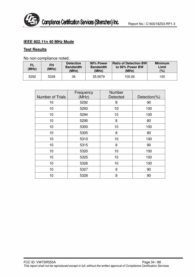
IEEE 802.11n 40 MHz Mode
Test Results
No non-compliance noted.
FL (MHz)
FH (MHz)
Detection Bandwidth
(MHz)
99% Power Bandwidth
(MHz)
Ratio of Detection BW to 99% Power BW
(MHz)
Minimum Limit (%)
5292 5328 36 35.9079 100.26 100
Number of Trials Frequency
(MHz) Number Detected Detection(%)
10 5292 9 90
10 5293 10 100
10 5294 10 100
10 5295 8 80
10 5300 10 100
10 5305 8 80
10 5310 10 100
10 5315 9 90
10 5320 10 100
10 5325 10 100
10 5326 10 100
10 5327 9 90
10 5328 9 90

Report No.: C160218Z03-RP1-3
FCC ID: VW7SR555A Page 35 / 88 This report shall not be reproduced except in full, without the written approval of Compliance Certification Services.
IEEE 802.11ac 80 MHz Mode
Test Results
No non-compliance noted.
FL (MHz)
FH (MHz)
Detection Bandwidth
(MHz)
99% Power Bandwidth
(MHz)
Ratio of Detection BW to 99% Power BW
(MHz)
Minimum Limit (%)
5252 5328 76 74.8291 101.56 100
Number of Trials Frequency
(MHz) Number Detected Detection(%)
10 5252 9 90
10 5253 10 100
10 5254 10 100
10 5255 9 90
10 5260 10 100
10 5265 9 90
10 5270 10 100
10 5275 10 100
10 5280 10 100
10 5285 8 80
10 5290 10 100
10 5295 8 80
10 5300 10 100
10 5305 9 90
10 5310 10 100
10 5315 10 100
10 5320 9 90
10 5325 10 100
10 5326 9 90
10 5327 10 100
10 5328 9 90

Report No.: C160218Z03-RP1-3
FCC ID: VW7SR555A Page 36 / 88 This report shall not be reproduced except in full, without the written approval of Compliance Certification Services.
Statistical Performance Check
IEEE 802.11n 20 MHz Mode
Test Results
No non-compliance noted:
Summary of Detection Probability
Radar Type Number of Trials Detection
(%) Limit (%)
Pass / Fail
Type 0 30 96.67 60 Pass
Type 2 30 93.33 60 Pass
Type 3 30 96.67 60 Pass
Type 4 30 96.67 60 Pass
Aggregate of 1 to 4 30 95.83 80 Pass
Type 5 30 96.67 70 Pass
Type 6 30 96.67 80 Pass

Report No.: C160218Z03-RP1-3
FCC ID: VW7SR555A Page 37 / 88 This report shall not be reproduced except in full, without the written approval of Compliance Certification Services.
Type 0 Detection Probability
Trial No. Successful Detection
(Yes/No) 1 YES
2 YES
3 YES
4 NO
5 YES
6 YES
7 YES
8 YES
9 YES
10 YES
11 YES
12 YES
13 YES
14 YES
15 YES
16 YES
17 YES
18 YES
19 YES
20 YES
21 YES
22 YES
23 YES
24 YES
25 YES
26 YES
27 YES
30 YES

Report No.: C160218Z03-RP1-3
FCC ID: VW7SR555A Page 38 / 88 This report shall not be reproduced except in full, without the written approval of Compliance Certification Services.
Type 2 Detection Probability
Trial No. Successful Detection
(Yes/No) 1 YES
2 YES
3 YES
4 NO
5 YES
6 YES
7 YES
8 YES
9 YES
10 YES
11 YES
12 NO
13 YES
14 YES
15 YES
16 YES
17 YES
18 YES
19 YES
20 YES
21 YES
22 YES
23 YES
24 YES
25 YES
26 YES
27 YES
30 YES

Report No.: C160218Z03-RP1-3
FCC ID: VW7SR555A Page 39 / 88 This report shall not be reproduced except in full, without the written approval of Compliance Certification Services.
Type 3 Detection Probability
Trial No. Successful Detection
(Yes/No) 1 YES
2 YES
3 NO
4 YES
5 YES
6 YES
7 YES
8 YES
9 YES
10 YES
11 YES
12 YES
13 YES
14 YES
15 YES
16 YES
17 YES
18 YES
19 YES
20 YES
21 YES
22 YES
23 YES
24 YES
25 YES
26 YES
27 YES
30 YES

Report No.: C160218Z03-RP1-3
FCC ID: VW7SR555A Page 40 / 88 This report shall not be reproduced except in full, without the written approval of Compliance Certification Services.
Type 4 Detection Probability
Trial No. Successful Detection
(Yes/No) 1 YES
2 YES
3 YES
4 YES
5 YES
6 YES
7 YES
8 YES
9 YES
10 YES
11 YES
12 YES
13 YES
14 YES
15 YES
16 YES
17 YES
18 YES
19 YES
20 YES
21 YES
22 YES
23 YES
24 YES
25 NO
26 YES
27 YES
30 YES

Report No.: C160218Z03-RP1-3
FCC ID: VW7SR555A Page 41 / 88 This report shall not be reproduced except in full, without the written approval of Compliance Certification Services.
Type 5 Detection Probability
Trial No. Successful Detection
(Yes/No) 1 YES
2 YES
3 YES
4 YES
5 YES
6 YES
7 YES
8 YES
9 YES
10 YES
11 YES
12 YES
13 YES
14 YES
15 YES
16 YES
17 YES
18 YES
19 YES
20 YES
21 YES
22 YES
23 YES
24 YES
25 NO
26 YES
27 YES
30 YES

Report No.: C160218Z03-RP1-3
FCC ID: VW7SR555A Page 42 / 88 This report shall not be reproduced except in full, without the written approval of Compliance Certification Services.
Type 6 Detection Probability
Trial No. Successful Detection
(Yes/No) 1 YES
2 YES
3 YES
4 YES
5 YES
6 YES
7 YES
8 YES
9 YES
10 YES
11 YES
12 YES
13 YES
14 YES
15 YES
16 YES
17 YES
18 YES
19 YES
20 YES
21 YES
22 YES
23 YES
24 YES
25 NO
26 YES
27 YES
30 YES

Report No.: C160218Z03-RP1-3
FCC ID: VW7SR555A Page 43 / 88 This report shall not be reproduced except in full, without the written approval of Compliance Certification Services.
IEEE 802.11n 40 MHz Mode
Test Results
No non-compliance noted:
Summary of Detection Probability
Radar Type Number of Trials Detection
(%) Limit (%)
Pass / Fail
Type 0 30 93.33 60 Pass
Type 2 30 90.00 60 Pass
Type 3 30 93.33 60 Pass
Type 4 30 93.33 60 Pass
Aggregate of 1 to 4 30 92.50 80 Pass
Type 5 30 93.33 70 Pass
Type 6 30 93.33 80 Pass

Report No.: C160218Z03-RP1-3
FCC ID: VW7SR555A Page 44 / 88 This report shall not be reproduced except in full, without the written approval of Compliance Certification Services.
Type 0 Detection Probability
Trial No. Successful Detection
(Yes/No) 1 YES
2 YES
3 YES
4 NO
5 YES
6 YES
7 YES
8 YES
9 YES
10 YES
11 YES
12 YES
13 YES
14 YES
15 YES
16 YES
17 YES
18 YES
19 YES
20 YES
21 NO
22 YES
23 YES
24 YES
25 YES
26 YES
27 YES
30 YES

Report No.: C160218Z03-RP1-3
FCC ID: VW7SR555A Page 45 / 88 This report shall not be reproduced except in full, without the written approval of Compliance Certification Services.
Type 2 Detection Probability
Trial No. Successful Detection
(Yes/No) 1 YES
2 YES
3 YES
4 NO
5 YES
6 YES
7 YES
8 YES
9 YES
10 YES
11 YES
12 NO
13 YES
14 YES
15 YES
16 YES
17 YES
18 NO
19 YES
20 YES
21 YES
22 YES
23 YES
24 YES
25 YES
26 YES
27 YES
30 YES

Report No.: C160218Z03-RP1-3
FCC ID: VW7SR555A Page 46 / 88 This report shall not be reproduced except in full, without the written approval of Compliance Certification Services.
Type 3 Detection Probability
Trial No. Successful Detection
(Yes/No) 1 YES
2 YES
3 NO
4 YES
5 YES
6 YES
7 YES
8 YES
9 YES
10 YES
11 YES
12 YES
13 YES
14 YES
15 YES
16 YES
17 NO
18 YES
19 YES
20 YES
21 YES
22 YES
23 YES
24 YES
25 YES
26 YES
27 YES
30 YES

Report No.: C160218Z03-RP1-3
FCC ID: VW7SR555A Page 47 / 88 This report shall not be reproduced except in full, without the written approval of Compliance Certification Services.
Type 4 Detection Probability
Trial No. Successful Detection
(Yes/No) 1 YES
2 YES
3 YES
4 YES
5 YES
6 YES
7 NO
8 YES
9 YES
10 YES
11 YES
12 YES
13 YES
14 YES
15 YES
16 YES
17 YES
18 YES
19 YES
20 YES
21 YES
22 YES
23 YES
24 YES
25 NO
26 YES
27 YES
30 YES
Report No.: C160218Z03-RP1-3
FCC ID: VW7SR555A Page 48 / 88 This report shall not be reproduced except in full, without the written approval of Compliance Certification Services.
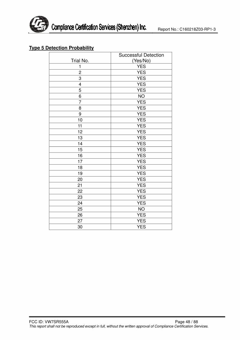
Type 5 Detection Probability
Trial No. Successful Detection
(Yes/No) 1 YES
2 YES
3 YES
4 YES
5 YES
6 NO
7 YES
8 YES
9 YES
10 YES
11 YES
12 YES
13 YES
14 YES
15 YES
16 YES
17 YES
18 YES
19 YES
20 YES
21 YES
22 YES
23 YES
24 YES
25 NO
26 YES
27 YES
30 YES
Report No.: C160218Z03-RP1-3
FCC ID: VW7SR555A Page 49 / 88 This report shall not be reproduced except in full, without the written approval of Compliance Certification Services.
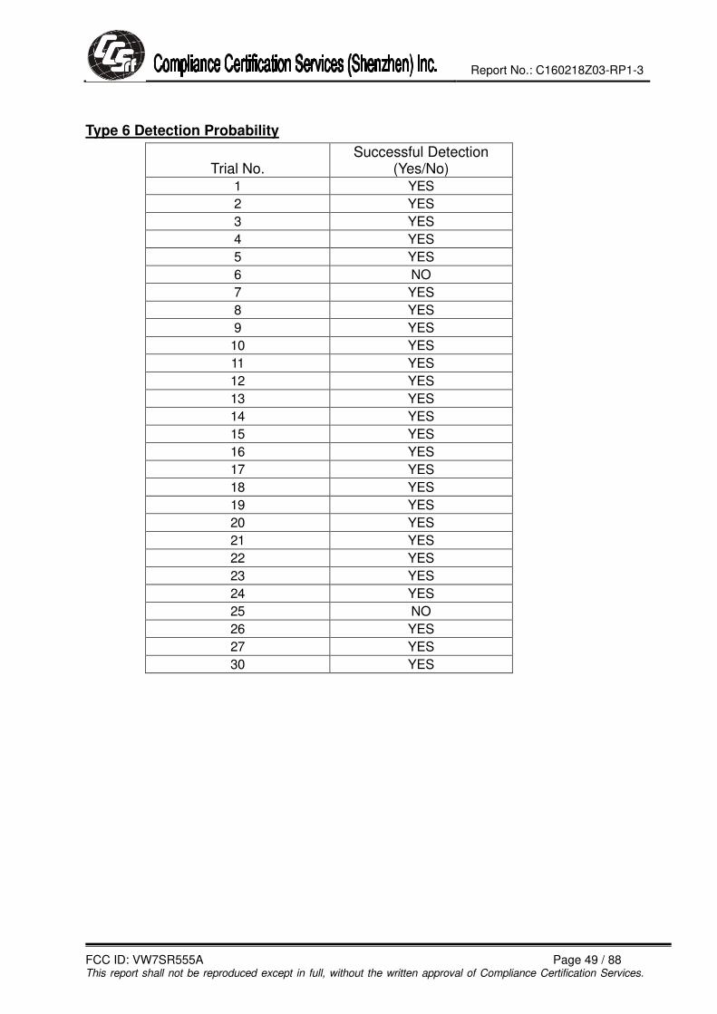
Type 6 Detection Probability
Trial No. Successful Detection
(Yes/No) 1 YES
2 YES
3 YES
4 YES
5 YES
6 NO
7 YES
8 YES
9 YES
10 YES
11 YES
12 YES
13 YES
14 YES
15 YES
16 YES
17 YES
18 YES
19 YES
20 YES
21 YES
22 YES
23 YES
24 YES
25 NO
26 YES
27 YES
30 YES

Report No.: C160218Z03-RP1-3
FCC ID: VW7SR555A Page 50 / 88 This report shall not be reproduced except in full, without the written approval of Compliance Certification Services.
IEEE 802.11ac 80 MHz Mode
Test Results
No non-compliance noted:
Summary of Detection Probability
Radar Type Number of Trials Detection
(%) Limit (%)
Pass / Fail
Type 0 30 93.33 60 Pass
Type 2 30 93.33 60 Pass
Type 3 30 93.33 60 Pass
Type 4 30 93.33 60 Pass
Aggregate of 1 to 4 30 93.33 80 Pass
Type 5 30 90.00 70 Pass
Type 6 30 93.33 80 Pass

Report No.: C160218Z03-RP1-3
FCC ID: VW7SR555A Page 51 / 88 This report shall not be reproduced except in full, without the written approval of Compliance Certification Services.
Type 0 Detection Probability
Trial No. Successful Detection
(Yes/No) 1 YES
2 YES
3 YES
4 YES
5 YES
6 YES
7 YES
8 YES
9 YES
10 YES
11 NO
12 YES
13 YES
14 YES
15 YES
16 YES
17 YES
18 YES
19 YES
20 YES
21 YES
22 NO
23 YES
24 YES
25 YES
26 YES
27 YES
30 YES

Report No.: C160218Z03-RP1-3
FCC ID: VW7SR555A Page 52 / 88 This report shall not be reproduced except in full, without the written approval of Compliance Certification Services.
Type 2 Detection Probability
Trial No. Successful Detection
(Yes/No) 1 YES
2 YES
3 YES
4 YES
5 NO
6 YES
7 YES
8 YES
9 YES
10 YES
11 YES
12 YES
13 YES
14 YES
15 YES
16 YES
17 YES
18 YES
19 YES
20 YES
21 YES
22 NO
23 YES
24 YES
25 YES
26 YES
27 YES
30 YES

Report No.: C160218Z03-RP1-3
FCC ID: VW7SR555A Page 53 / 88 This report shall not be reproduced except in full, without the written approval of Compliance Certification Services.
Type 3 Detection Probability
Trial No. Successful Detection
(Yes/No) 1 YES
2 YES
3 YES
4 YES
5 NO
6 YES
7 YES
8 YES
9 YES
10 YES
11 YES
12 YES
13 YES
14 YES
15 YES
16 YES
17 YES
18 YES
19 YES
20 YES
21 YES
22 YES
23 YES
24 YES
25 NO
26 YES
27 YES
30 YES

Report No.: C160218Z03-RP1-3
FCC ID: VW7SR555A Page 54 / 88 This report shall not be reproduced except in full, without the written approval of Compliance Certification Services.
Type 4 Detection Probability
Trial No. Successful Detection
(Yes/No) 1 YES
2 YES
3 YES
4 YES
5 NO
6 YES
7 YES
8 YES
9 YES
10 NO
11 YES
12 YES
13 YES
14 YES
15 YES
16 YES
17 YES
18 YES
19 YES
20 YES
21 YES
22 YES
23 YES
24 YES
25 YES
26 YES
27 YES
30 YES

Report No.: C160218Z03-RP1-3
FCC ID: VW7SR555A Page 55 / 88 This report shall not be reproduced except in full, without the written approval of Compliance Certification Services.
Type 5 Detection Probability
Trial No. Successful Detection
(Yes/No) 1 YES
2 YES
3 YES
4 YES
5 YES
6 YES
7 YES
8 NO
9 YES
10 YES
11 YES
12 YES
13 YES
14 YES
15 YES
16 NO
17 YES
18 YES
19 YES
20 YES
21 YES
22 NO
23 YES
24 YES
25 YES
26 YES
27 YES
30 YES

Report No.: C160218Z03-RP1-3
FCC ID: VW7SR555A Page 56 / 88 This report shall not be reproduced except in full, without the written approval of Compliance Certification Services.
Type 6 Detection Probability
Trial No. Successful Detection
(Yes/No) 1 YES
2 YES
3 YES
4 YES
5 YES
6 YES
7 YES
8 YES
9 YES
10 YES
11 YES
12 YES
13 NO
14 YES
15 YES
16 YES
17 NO
18 YES
19 YES
20 YES
21 YES
22 YES
23 YES
24 YES
25 YES
26 YES
27 YES
30 YES
Report No.: C160218Z03-RP1-3
FCC ID: VW7SR555A Page 57 / 88 This report shall not be reproduced except in full, without the written approval of Compliance Certification Services.
CHANNEL MOVE TIME AND CHANNEL CLOSING TRANSMISSION TIME
General Reporting Notes
The reference marker is set at the end of last radar pulse.
Type 0 Radar Reporting Notes
The delta marker is set at the end of the last WLAN transmission following the radar pulse. This delta is the channel move time.
The aggregate channel closing transmission time is calculated as follows:
Aggregate Transmission Time =
(Number of analyzer bins showing transmission) * (dwell time per bin)
The observation period over which the aggregate time is calculated
Begins no later than (Reference Marker + 200 msec)
and
Ends no earlier than (Reference Marker + 10 sec).

Report No.: C160218Z03-RP1-3
FCC ID: VW7SR555A Page 58 / 88 This report shall not be reproduced except in full, without the written approval of Compliance Certification Services.
HIGH BAND RESULTS
IEEE 802.11ac 80 MHz Mode
Type 0 Channel Move Time Results
No non-compliance noted.
Channel Move Time (s)
Limit (s)
1.198 10

Report No.: C160218Z03-RP1-3
FCC ID: VW7SR555A Page 59 / 88 This report shall not be reproduced except in full, without the written approval of Compliance Certification Services.
Type 0 Channel Closing Transmission Time Results
No non-compliance noted.
Channel Closing Transmission Time
(ms)
Limit
(ms)
Margin
(ms)
30.00 60 -30.00
Only intermittent transmissions are observed during the aggregate monitoring period.

Report No.: C160218Z03-RP1-3
FCC ID: VW7SR555A Page 60 / 88 This report shall not be reproduced except in full, without the written approval of Compliance Certification Services.

Report No.: C160218Z03-RP1-3
FCC ID: VW7SR555A Page 61 / 88 This report shall not be reproduced except in full, without the written approval of Compliance Certification Services.
Non-Occupancy Period
Type 0 Non-Occupancy Period Test Results
No non-compliance noted: No EUT transmissions were observed on the test channel
during the 30 minute observation time.
Report No.: C160218Z03-RP1-3
FCC ID: VW7SR555A Page 62 / 88 This report shall not be reproduced except in full, without the written approval of Compliance Certification Services.
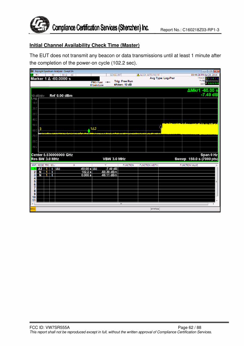
Initial Channel Availability Check Time (Master)
The EUT does not transmit any beacon or data transmissions until at least 1 minute after
the completion of the power-on cycle (102.2 sec).

Report No.: C160218Z03-RP1-3
FCC ID: VW7SR555A Page 63 / 88 This report shall not be reproduced except in full, without the written approval of Compliance Certification Services.

Report No.: C160218Z03-RP1-3
FCC ID: VW7SR555A Page 64 / 88 This report shall not be reproduced except in full, without the written approval of Compliance Certification Services.
DETECTION BANDWIDTH
IEEE 802.11n 20 MHz Mode
Test Results
No non-compliance noted.
FL (MHz)
FH (MHz)
Detection Bandwidth
(MHz)
99% Power Bandwidth
(MHz)
Ratio of Detection BW to 99% Power BW
(MHz)
Minimum Limit (%)
5491 5509 18 17.6540 101.96 100
Number of Trials Frequency
(MHz) Number Detected Detection(%)
10 5491 9 90
10 5492 10 100
10 5493 10 100
10 5494 9 90
10 5495 10 100
10 5500 10 100
10 5505 10 100
10 5506 8 80
10 5507 10 100
10 5508 8 80
10 5509 10 100

Report No.: C160218Z03-RP1-3
FCC ID: VW7SR555A Page 65 / 88 This report shall not be reproduced except in full, without the written approval of Compliance Certification Services.
IEEE 802.11n 40 MHz Mode
Test Results
No non-compliance noted.
FL (MHz)
FH (MHz)
Detection Bandwidth
(MHz)
99% Power Bandwidth
(MHz)
Ratio of Detection BW to 99% Power BW
(MHz)
Minimum Limit (%)
5492 5528 36 35.9031 100.27 100
Number of Trials Frequency
(MHz) Number Detected Detection(%)
10 5492 9 90
10 5493 10 100
10 5494 10 100
10 5495 8 80
10 5500 10 100
10 5505 8 80
10 5510 10 100
10 5515 9 90
10 5520 10 100
10 5525 10 100
10 5526 10 100
10 5527 9 90
10 5528 9 90
Report No.: C160218Z03-RP1-3
FCC ID: VW7SR555A Page 66 / 88 This report shall not be reproduced except in full, without the written approval of Compliance Certification Services.
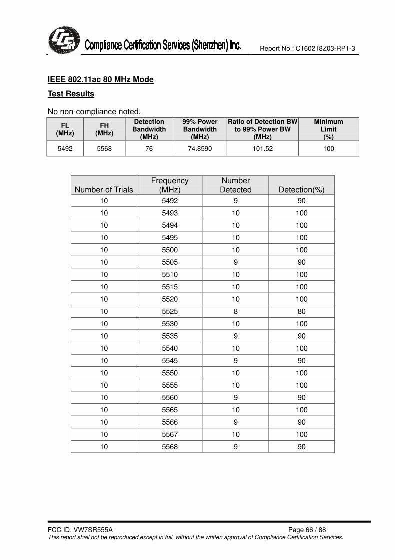
IEEE 802.11ac 80 MHz Mode
Test Results
No non-compliance noted.
FL (MHz)
FH (MHz)
Detection Bandwidth
(MHz)
99% Power Bandwidth
(MHz)
Ratio of Detection BW to 99% Power BW
(MHz)
Minimum Limit (%)
5492 5568 76 74.8590 101.52 100
Number of Trials Frequency
(MHz) Number Detected Detection(%)
10 5492 9 90
10 5493 10 100
10 5494 10 100
10 5495 10 100
10 5500 10 100
10 5505 9 90
10 5510 10 100
10 5515 10 100
10 5520 10 100
10 5525 8 80
10 5530 10 100
10 5535 9 90
10 5540 10 100
10 5545 9 90
10 5550 10 100
10 5555 10 100
10 5560 9 90
10 5565 10 100
10 5566 9 90
10 5567 10 100
10 5568 9 90
Report No.: C160218Z03-RP1-3
FCC ID: VW7SR555A Page 67 / 88 This report shall not be reproduced except in full, without the written approval of Compliance Certification Services.
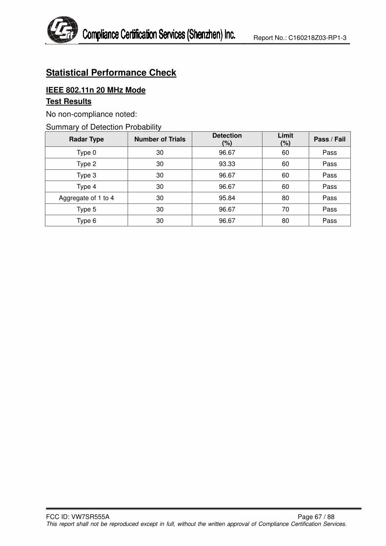
Statistical Performance Check
IEEE 802.11n 20 MHz Mode
Test Results
No non-compliance noted:
Summary of Detection Probability
Radar Type Number of Trials Detection
(%) Limit (%)
Pass / Fail
Type 0 30 96.67 60 Pass
Type 2 30 93.33 60 Pass
Type 3 30 96.67 60 Pass
Type 4 30 96.67 60 Pass
Aggregate of 1 to 4 30 95.84 80 Pass
Type 5 30 96.67 70 Pass
Type 6 30 96.67 80 Pass

Report No.: C160218Z03-RP1-3
FCC ID: VW7SR555A Page 68 / 88 This report shall not be reproduced except in full, without the written approval of Compliance Certification Services.
Type 0 Detection Probability
Trial No. Successful Detection
(Yes/No) 1 YES
2 YES
3 YES
4 YES
5 YES
6 YES
7 YES
8 YES
9 YES
10 YES
11 YES
12 YES
13 YES
14 YES
15 YES
16 YES
17 YES
18 YES
19 YES
20 YES
21 NO
22 YES
23 YES
24 YES
25 YES
26 YES
27 YES
30 YES

Report No.: C160218Z03-RP1-3
FCC ID: VW7SR555A Page 69 / 88 This report shall not be reproduced except in full, without the written approval of Compliance Certification Services.
Type 2 Detection Probability
Trial No. Successful Detection
(Yes/No) 1 YES
2 YES
3 YES
4 YES
5 YES
6 YES
7 NO
8 YES
9 YES
10 YES
11 YES
12 YES
13 YES
14 YES
15 YES
16 YES
17 YES
18 YES
19 YES
20 YES
21 NO
22 YES
23 YES
24 YES
25 YES
26 YES
27 YES
30 YES

Report No.: C160218Z03-RP1-3
FCC ID: VW7SR555A Page 70 / 88 This report shall not be reproduced except in full, without the written approval of Compliance Certification Services.
Type 3 Detection Probability
Trial No. Successful Detection
(Yes/No) 1 YES
2 YES
3 YES
4 YES
5 YES
6 YES
7 YES
8 YES
9 YES
10 YES
11 YES
12 YES
13 YES
14 YES
15 YES
16 YES
17 YES
18 YES
19 YES
20 YES
21 NO
22 YES
23 YES
24 YES
25 YES
26 YES
27 YES
30 YES

Report No.: C160218Z03-RP1-3
FCC ID: VW7SR555A Page 71 / 88 This report shall not be reproduced except in full, without the written approval of Compliance Certification Services.
Type 4 Detection Probability
Trial No. Successful Detection
(Yes/No) 1 YES
2 YES
3 YES
4 YES
5 YES
6 YES
7 YES
8 YES
9 YES
10 YES
11 YES
12 YES
13 YES
14 YES
15 YES
16 YES
17 YES
18 YES
19 YES
20 YES
21 NO
22 YES
23 YES
24 YES
25 YES
26 YES
27 YES
30 YES

Report No.: C160218Z03-RP1-3
FCC ID: VW7SR555A Page 72 / 88 This report shall not be reproduced except in full, without the written approval of Compliance Certification Services.
Type 5 Detection Probability
Trial No. Successful Detection
(Yes/No) 1 YES
2 YES
3 YES
4 YES
5 YES
6 YES
7 YES
8 YES
9 YES
10 YES
11 YES
12 YES
13 YES
14 YES
15 YES
16 YES
17 YES
18 YES
19 YES
20 NO
21 YES
22 YES
23 YES
24 YES
25 YES
26 YES
27 YES
30 YES

Report No.: C160218Z03-RP1-3
FCC ID: VW7SR555A Page 73 / 88 This report shall not be reproduced except in full, without the written approval of Compliance Certification Services.
Type 6 Detection Probability
Trial No. Successful Detection
(Yes/No) 1 YES
2 YES
3 YES
4 YES
5 YES
6 YES
7 YES
8 YES
9 YES
10 YES
11 YES
12 YES
13 YES
14 YES
15 YES
16 YES
17 YES
18 YES
19 YES
20 YES
21 NO
22 YES
23 YES
24 YES
25 YES
26 YES
27 YES
30 YES

Report No.: C160218Z03-RP1-3
FCC ID: VW7SR555A Page 74 / 88 This report shall not be reproduced except in full, without the written approval of Compliance Certification Services.
IEEE 802.11n 40 MHz Mode
Test Results
No non-compliance noted:
Summary of Detection Probability
Radar Type Number of Trials Detection
(%) Limit (%)
Pass / Fail
Type 0 30 93.33 60 Pass
Type 2 30 90.00 60 Pass
Type 3 30 93.33 60 Pass
Type 4 30 90.00 60 Pass
Aggregate of 1 to 4 30 91.65 80 Pass
Type 5 30 90.00 70 Pass
Type 6 30 93.33 80 Pass

Report No.: C160218Z03-RP1-3
FCC ID: VW7SR555A Page 75 / 88 This report shall not be reproduced except in full, without the written approval of Compliance Certification Services.
Type 0 Detection Probability
Trial No. Successful Detection
(Yes/No) 1 YES
2 YES
3 YES
4 YES
5 YES
6 YES
7 YES
8 YES
9 YES
10 YES
11 YES
12 YES
13 NO
14 YES
15 YES
16 YES
17 YES
18 YES
19 YES
20 YES
21 YES
22 YES
23 NO
24 YES
25 YES
26 YES
27 YES
30 YES

Report No.: C160218Z03-RP1-3
FCC ID: VW7SR555A Page 76 / 88 This report shall not be reproduced except in full, without the written approval of Compliance Certification Services.
Type 2 Detection Probability
Trial No. Successful Detection
(Yes/No) 1 YES
2 YES
3 YES
4 NO
5 YES
6 YES
7 YES
8 YES
9 YES
10 YES
11 YES
12 YES
13 NO
14 YES
15 YES
16 YES
17 YES
18 YES
19 YES
20 YES
21 YES
22 YES
23 NO
24 YES
25 YES
26 YES
27 YES
30 YES

Report No.: C160218Z03-RP1-3
FCC ID: VW7SR555A Page 77 / 88 This report shall not be reproduced except in full, without the written approval of Compliance Certification Services.
Type 3 Detection Probability
Trial No. Successful Detection
(Yes/No) 1 YES
2 YES
3 YES
4 YES
5 YES
6 YES
7 YES
8 YES
9 YES
10 YES
11 YES
12 YES
13 YES
14 YES
15 NO
16 YES
17 YES
18 YES
19 YES
20 YES
21 YES
22 YES
23 NO
24 YES
25 YES
26 YES
27 YES
30 YES

Report No.: C160218Z03-RP1-3
FCC ID: VW7SR555A Page 78 / 88 This report shall not be reproduced except in full, without the written approval of Compliance Certification Services.
Type 4 Detection Probability
Trial No. Successful Detection
(Yes/No) 1 YES
2 YES
3 YES
4 NO
5 YES
6 YES
7 YES
8 YES
9 NO
10 YES
11 YES
12 YES
13 YES
14 YES
15 YES
16 YES
17 YES
18 YES
19 YES
20 YES
21 YES
22 YES
23 NO
24 YES
25 YES
26 YES
27 YES
30 YES

Report No.: C160218Z03-RP1-3
FCC ID: VW7SR555A Page 79 / 88 This report shall not be reproduced except in full, without the written approval of Compliance Certification Services.
Type 5 Detection Probability
Trial No. Successful Detection
(Yes/No) 1 YES
2 YES
3 YES
4 YES
5 YES
6 YES
7 YES
8 YES
9 NO
10 YES
11 YES
12 YES
13 YES
14 NO
15 YES
16 YES
17 YES
18 YES
19 YES
20 YES
21 YES
22 YES
23 NO
24 YES
25 YES
26 YES
27 YES
30 YES
Report No.: C160218Z03-RP1-3
FCC ID: VW7SR555A Page 80 / 88 This report shall not be reproduced except in full, without the written approval of Compliance Certification Services.
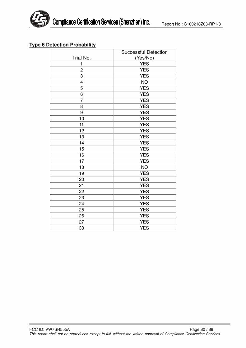
Type 6 Detection Probability
Trial No. Successful Detection
(Yes/No) 1 YES
2 YES
3 YES
4 NO
5 YES
6 YES
7 YES
8 YES
9 YES
10 YES
11 YES
12 YES
13 YES
14 YES
15 YES
16 YES
17 YES
18 NO
19 YES
20 YES
21 YES
22 YES
23 YES
24 YES
25 YES
26 YES
27 YES
30 YES

Report No.: C160218Z03-RP1-3
FCC ID: VW7SR555A Page 81 / 88 This report shall not be reproduced except in full, without the written approval of Compliance Certification Services.
IEEE 802.11ac 80 MHz Mode
Test Results
No non-compliance noted:
Summary of Detection Probability
Radar Type Number of Trials Detection
(%) Limit (%)
Pass / Fail
Type 0 30 93.33 60 Pass
Type 2 30 93.33 60 Pass
Type 3 30 96.67 60 Pass
Type 4 30 96.67 60 Pass
Aggregate of 1 to 4 30 95.75 80 Pass
Type 5 30 90.00 70 Pass
Type 6 30 93.33 80 Pass

Report No.: C160218Z03-RP1-3
FCC ID: VW7SR555A Page 82 / 88 This report shall not be reproduced except in full, without the written approval of Compliance Certification Services.
Type 0 Detection Probability
Trial No. Successful Detection
(Yes/No) 1 YES
2 YES
3 YES
4 YES
5 YES
6 YES
7 YES
8 YES
9 YES
10 YES
11 YES
12 YES
13 NO
14 YES
15 YES
16 YES
17 YES
18 YES
19 YES
20 YES
21 YES
22 YES
23 NO
24 YES
25 YES
26 YES
27 YES
30 YES

Report No.: C160218Z03-RP1-3
FCC ID: VW7SR555A Page 83 / 88 This report shall not be reproduced except in full, without the written approval of Compliance Certification Services.
Type 2 Detection Probability
Trial No. Successful Detection
(Yes/No) 1 YES
2 YES
3 YES
4 YES
5 YES
6 YES
7 YES
8 YES
9 YES
10 YES
11 YES
12 YES
13 NO
14 YES
15 YES
16 YES
17 YES
18 YES
19 YES
20 YES
21 YES
22 YES
23 NO
24 YES
25 YES
26 YES
27 YES
30 YES

Report No.: C160218Z03-RP1-3
FCC ID: VW7SR555A Page 84 / 88 This report shall not be reproduced except in full, without the written approval of Compliance Certification Services.
Type 3 Detection Probability
Trial No. Successful Detection
(Yes/No) 1 YES
2 YES
3 YES
4 YES
5 YES
6 YES
7 YES
8 YES
9 YES
10 YES
11 YES
12 YES
13 YES
14 YES
15 YES
16 YES
17 YES
18 YES
19 YES
20 YES
21 YES
22 YES
23 NO
24 YES
25 YES
26 YES
27 YES
30 YES

Report No.: C160218Z03-RP1-3
FCC ID: VW7SR555A Page 85 / 88 This report shall not be reproduced except in full, without the written approval of Compliance Certification Services.
Type 4 Detection Probability
Trial No. Successful Detection
(Yes/No) 1 YES
2 YES
3 YES
4 YES
5 YES
6 YES
7 YES
8 YES
9 NO
10 YES
11 YES
12 YES
13 YES
14 YES
15 YES
16 YES
17 YES
18 YES
19 YES
20 YES
21 YES
22 YES
23 NO
24 YES
25 YES
26 YES
27 YES
30 YES

Report No.: C160218Z03-RP1-3
FCC ID: VW7SR555A Page 86 / 88 This report shall not be reproduced except in full, without the written approval of Compliance Certification Services.
Type 5 Detection Probability
Trial No. Successful Detection
(Yes/No) 1 YES
2 YES
3 YES
4 YES
5 YES
6 YES
7 YES
8 YES
9 NO
10 YES
11 YES
12 YES
13 YES
14 NO
15 YES
16 YES
17 YES
18 YES
19 YES
20 YES
21 YES
22 YES
23 NO
24 YES
25 YES
26 YES
27 YES
30 YES

Report No.: C160218Z03-RP1-3
FCC ID: VW7SR555A Page 87 / 88 This report shall not be reproduced except in full, without the written approval of Compliance Certification Services.
Type 6 Detection Probability
Trial No. Successful Detection
(Yes/No) 1 YES
2 YES
3 YES
4 NO
5 YES
6 YES
7 YES
8 YES
9 YES
10 YES
11 YES
12 YES
13 YES
14 YES
15 YES
16 YES
17 YES
18 NO
19 YES
20 YES
21 YES
22 YES
23 YES
24 YES
25 YES
26 YES
27 YES
30 YES

Report No.: C160218Z03-RP1-3
FCC ID: VW7SR555A Page 88 / 88 This report shall not be reproduced except in full, without the written approval of Compliance Certification Services.
APPENDIX I PHOTOGRAPHS OF TEST SETUP