fb4c manual de instalación
TRANSCRIPT

8/13/2019 FB4C Manual de Instalación
http://slidepdf.com/reader/full/fb4c-manual-de-instalacion 1/14
FB4CFY5B
Installation Instructions
FAN COIL UNITSFOR PURON REFRIGERANT
SIZES 018 TO 060
NOTE: Read the entire instruction manual before starting the
installation.
TABLE OF CONTENTS
PAGE
SAFETY CONSIDERATIONS 1. . . . . . . . . . . . . . . . . . . . . . . .
INTRODUCTION 1. . . . . . . . . . . . . . . . . . . . . . . . . . . . . . . . . .
HEATER PACKAGES 2. . . . . . . . . . . . . . . . . . . . . . . . . . . . . .
INSTALLATION 2. . . . . . . . . . . . . . . . . . . . . . . . . . . . . . . . . . .Step 1 — Check Equipment 2. . . . . . . . . . . . . . . . . . . . . . . . .
Step 2 — Mount Unit 2. . . . . . . . . . . . . . . . . . . . . . . . . . . . . .
Step 3 — Air Ducts 4. . . . . . . . . . . . . . . . . . . . . . . . . . . . . . .
Step 4 — Electrical Connections 4. . . . . . . . . . . . . . . . . . . . .
Step 5 — Refrigerant Tubing Connection and Evacuation 7. .
Step 6 — Refrigerant Flow--Control Device 7. . . . . . . . . . . . .
Step 7 — Condensate Drains 8. . . . . . . . . . . . . . . . . . . . . . . .
Step 8 — Accessories 9. . . . . . . . . . . . . . . . . . . . . . . . . . . . . .
Step 9 — Sequence of Operation 10. . . . . . . . . . . . . . . . . . . .
START--UP PROCEDURES 10. . . . . . . . . . . . . . . . . . . . . . . . .
CARE AND MAINTENANCE 10. . . . . . . . . . . . . . . . . . . . . . .
AIRFLOW PERFORMANCE TABLES 11. . . . . . . . . . . . . . . .
SAFETY CONSIDERATIONS
Improper installation, adjustment, alteration, service, maintenance,or use can cause explosion, fire, electrical shock, or otherconditions which may cause death, personal injury or propertydamage. Consult a qualified installer, service agency, or yourdistributor or branch for information or assistance. The qualifiedinstaller or agency must use factory--authorized kits or accessories
when modifying this product. Refer to the individual instructionspackaged with kits or accessories when installing.
Follow all safety codes. Wear safety glasses, protective clothingand work gloves. Have a fire extinguisher available. Read these
instructions thoroughly and follow all warnings or cautionsincluded in literature and attached to the unit. Consult localbuilding codes and the current editions of the National ElectricalCode (NEC) NFPA 70.
In Canada, refer to the current editions of the Canadian ElectricalCode CSA C22.1.
Recognize safety information. This is the safety--alert symbol .When you see this symbol on the unit and in instruction manuals,be alert to the potential for personal injury.
Understand the signal words DANGER , WARNING, andCAUTION. These words are used with the safety--alert symbol.DANGER identifies the most serious hazards which will result insevere personal injury or death. WARNING signifies hazards
which could result in personal injury or death. CAUTION is usedto identify unsafe practices which may result in minor personalinjury or product and property damage. NOTE is used to highlightsuggestions which will result in enhanced installation, reliability, oroperation.
ELECTRICAL OPERATION HAZARD
Failure to follow this warning could result in personal injuryor death.
Before installing or servicing unit, always turn off all power tounit. There may be more than 1 disconnect switch. Turn off accessory heater power if applicable. Lock out and tag switch
with a suitable warning label.
! WARNING
CUT HAZARD
Failure to follow this caution may result in personal injury.
Sheet metal parts may have sharp edges or burrs. Use care and wear appropriate protective clothing and gloves whenhandling parts.
CAUTION!
INTRODUCTIONModels FB4C and FY5B are Puron Fan Coils designed forinstallation flexibility. These units are designed to meet the low airleak requirements currently in effect.
FB4C uses a refrigerant piston metering device (018 thru 048) andTXV (060) with an X13 integral electronically commutated motorfor efficiency. These units have be designed for upflow, downflow(kit required), and horizontal orientations, including manufacturedand mobile home applications.
FY5B uses a refrigerant piston metering device (018 thru 048) with2--speed PSC (permanent split capacitor) motors and TXV with3--speed PSC motor for the 060 size, These units can be used forupflow or downflow (kit required) orientations, includingmanufactured and mobile homes applications.
These units require a field supplied air filter, and are designedspecifically for Puron refrigerant air conditioners and heat pumpsas shipped. These units are available for systems of 18,000 through60,000 Btuh nominal cooling capacity. Factory--authorized, field --installed electric heater packages are available in sizes 5 through30kW. See Product Data literature for all available accessory kits.

8/13/2019 FB4C Manual de Instalación
http://slidepdf.com/reader/full/fb4c-manual-de-instalacion 2/14
2
HEATER PACKAGESThis unit may or may not be equipped with an electric heaterpackage. For units not equipped with factory--installed heat, afactory--approved, field--installed, UL listed heater package isavailable from your equipment supplier. See unit rating plate for alist of factory--approved heaters. Heaters that are not factoryapproved could cause damage which would not be covered underthe equipment warranty. If fan coil contains a factory--installedheater package, minimum circuit ampacity (MCA) and maximumfuse/breaker may be different than units with a same sizefield--installed accessory heater. The differences is not an error and
is due to calculation difference per UL guidelines.INSTALLATION
Step 1 — Check Equipment
Unpack unit and move to final location. Remove carton taking carenot to damage unit. Inspect equipment for damage prior toinstallation. File claim with shipping company if shipment isdamaged or incomplete.
Locate unit rating plate which contains proper installationinformation. Check rating plate to be sure unit matches jobspecifications.
Step 2 — Mount Unit
Unit can stand or lie on floor, or hang from ceiling or wall. Allowspace for wiring, piping, and servicing unit.
IMPORTANT: When unit is installed over a finished ceilingand/or living area, building codes may require a field--supplied
secondary condensate pan to be installed under the entire unit.
Some localities may allow as an alternative, the running of a
separate, secondary condensate line. Consult local codes for
additional restrictions or precautions.
A. Upflow Installation
If return air is to be ducted through a floor, set unit on floor overopening and use 1/8 to 1/4 --in (3 to 6 mm) thick fireproof resilientgasket between duct, unit, and floor.
Side return is a field option on slope coil models. Cut opening perdimensions. (See Fig. 1.) A field--supplied bottom closure isrequired.
A COILUNITS
POWER ENTRY
OPTIONS
LOW VOLTENTRYOPTIONS
FIELD MODIFIEDSIDE RETURNLOCATION FORSLOPE COILUNITS ONLY
FIELD SUPPLIED
RETURN PLENUM
UPFLOW/DOWNFLOWSECONDARY DRAIN
UPFLOW/DOWNFLOW
PRIMARY DRAIN
UNIT
018
024 - 030
A
12" (305 mm)
17" (432 mm)
A
1.5" (38 mm)
2.5"(64 mm)
19" (483 mm)
FIELD SUPPLIED
SUPPLY DUCT
UPFLOW/DOWNFLOWSECONDARY DRAIN
UPFLOW/DOWNFLOWPRIMARY DRAIN
036 19" (483 mm)
018 - 048 21" (533 mm) FRONT SERVICE060 - 060 24" (610mm) CLEARANCE
A07565
Fig. 1 -- Slope Coil Unit in Upflow Application
B. Downflow Installation
In this application, field conversion of the evaporator is requiredusing accessory downflow kit along with an accessory base kit.Use fireproof resilient gasket, 1/8 to 1/4--in (3 to 6 mm) thick,between duct, unit, and floor.
UNIT OR PROPERTY DAMAGE HAZARD
Failure to follow this caution may result in product or propertydamage.
The conversion of the fan coil to downflow requires specialprocedures for the condensate drains on both A--coil and slopeunits. The vertical drains have an overflow hole between theprimary and secondary drain holes. This hole is plugged for allapplications except downflow, but must be used for downflow.
During the conversion process, remove the plastic capcovering the vertical drains only and discard. Remove the plugfrom the overflow hole and discard. At completion of thedownflow installation, caulk around the vertical pan fitting todoor joint to retain the low air leak performance of the unit.
CAUTION!
NOTE: To convert units for downflow applications, refer to
Installation Instructions supplied with kit for proper installation.
For slope fan coils, use kit Part No. KFADC0201SLP. For A--coils,
use kit Part No. KFADC0401ACL. Use fireproof resilient gasket,
1/8 to 1/4 --in (3 to 6 mm) thick, between duct, unit, and floor.
NOTE: Gasket kit number KFAHD0101SLP is also required for
all downflow applications to maintain low air leak/low sweat
performance.
C. Horizontal Installation (FB4C only)Units must not be installed with access panels facing up or down.
All other units are factory built for horizontal left installation. (SeeFig. 2 and 3.) When suspending unit from ceiling, dimples incasing indicate suitable location of screws for mounting metalsupport straps. (See Fig. 2.)
PROPERTY DAMAGE HAZARD
Failure to follow this caution may result in product or propertydamage.
For optimum condensate drainage performance in horizontal
installations, unit should be leveled along its length and width.
CAUTION!
For horizontal applications having high return static and humidreturn air, the Water Management Kit, KFAHC0125AAA, mayneed to be used to assist in water management.
UNIT
FIELDSUPPLIEDHANGINGSTRAPS
LOW VOLTENTRYOPTIONS
POWERENTRY OPTIONS
SECONDARYDRAIN
018-048 21" (533 mm)060-060 24" (610 mm)FRONT SERVICECLEARANCE(FULL FACEOF UNIT)
SECONDARYDRAIN
A-COIL
HORIZONTAL LEFT
PRIMARYDRAIN
PRIMARYDRAIN
1.75" (44 mm)FILTER ACCESSCLEARANCE
A07566
Fig. 2 -- Slope Coil Unit in Horizontal Left Application
(FB4C only)
F B 4 C
/ F Y 5 B

8/13/2019 FB4C Manual de Instalación
http://slidepdf.com/reader/full/fb4c-manual-de-instalacion 3/14
3
A
B
C
FACTORY SHIPPEDHORIZONTAL LEFT
APPLICATION
AIR SEAL ASSEMBLY
HORIZONTALDRAIN PAN
REFRIGERANTCONNECTIONS
SECONDARY DRAIN
HORIZONTAL LEFT
PRIMARY DRAINHORIZONTAL LEFT
COILSUPPORT
RAIL
COILBRACKET
DRAIN PANSUPPORTBRACKET
COILBRACKET
A00072
Fig. 3 -- A--Coil in Horizontal Left Application
(Factory Ready FB4C only)
NOTE: Modular units can be disassembled and components
moved separately to installation area for reassembly. This process
accommodates small scuttle holes and limiting entrances to
installation sites. (See Fig. 4.)
2 SCREWS
2 SCREWS
REAR CORNERBRACKET
BLOWER BOX
COIL BOX
2 SCREWS
A95293
Fig. 4 -- Removal of Brackets on Modular Units Horizontal
Right Conversion of Units With Slope Coils (FB4C only)
NOTE: Gasket kit number KFAHD0101SLP is required for
horizontal slope coil conversion to maintain low air leak/low sweat
performance.
1. Remove blower and coil access panel and fitting panel. (SeeFig. 5.)
2. Remove coil mounting screw securing coil assembly toright side casing flange.
3. Remove coil assembly.
4. Lay fan coil unit on its right side and reinstall coil assembly with condensate pan down. (See Fig. 5.)
5. Attach coil to casing flange using coil mounting screw pre-viously removed.
6. Make sure the pan cap in the fitting door is properly seatedon the fitting door to retain the low air leak rating of theunit.
7. Add gaskets from kit KFAHD per kit instructions.
8. Align holes with tubing connections and condensate panconnections, and reinstall access panels and fitting panel.
Make sure liquid and suction tube grommets are in place to preventair leaks and cabinet sweating. Install after brazing.
COIL MOUNTINGSCREW
BLOWER ASSEMBLY
REFRIGERANTCONNECTIONS
SECONDARY DRAIN
PRIMARY DRAINDRAINPAN
SLOPE COILSKI
COILSUPPORT
RAIL
A03001
Fig. 5 -- Conversion for Horizontal Right Applications
Using a Slope Coil (FB4C only)
Horizontal Right Conversion of Units With A--Coils
1. Remove blower and coil access panels. (See Fig. 6.)
COILSUPPORT
RAIL
COILBRACKET
DRAIN PANSUPPORTBRACKET
COILSUPPORT
RAIL
COILBRACKET
HORIZONTALDRAIN PAN
PRIMARY DRAINHORIZONTAL RIGHT
SECONDARY DRAINHORIZONTAL RIGHT
REFRIGERANTCONNECTIONS
AIR SEAL ASSEMBLY
A
B
C
HORIZONTALRIGHT
APPLICATION
A00071
Fig. 6 -- Conversion for Horizontal Right Applications
Using A--Coil (FB4C only)
2. Remove metal clip securing fitting panel to condensate pan.Remove fitting panel.
3. Remove 2 snap--in clips securing A--coil in unit.
4. Slide coil and pan assembly out of unit.
5. Remove horizontal drain pan support bracket from coil sup-port rail on left side of unit and reinstall on coil support railon right side of unit. (See Fig. 7.)
DRAIN PANR IN P N
SUPPORT BRACKETUPPORT BR CKET
A07571
Fig. 7 -- Drain Pan Support Bracket
6. Convert air--seal assembly for horizontal right.
a. Remove air--seal assembly from coil by removing 4screws. (See Fig. 6.)
b. Remove air splitter (B) from coil seal assembly by re-moving 3 screws. (See Fig. 3--factory shipped inset.)

8/13/2019 FB4C Manual de Instalación
http://slidepdf.com/reader/full/fb4c-manual-de-instalacion 4/14
4
c. Remove filter plate (A) and install air splitter (B) inplace of filter plate.
d. Install filter plate (A) as shown in horizontal right ap-plication.
e. Remove condensate troughs (C) and install on oppositetube sheets.
f. Install hose onto plastic spout.
7. Install horizontal pan on right side of coil assembly.
8. Slide coil assembly into casing. Be sure coil bracket on eachcorner of vertical pan engages coil support rails.
9. Reinstall 2 snap--in clips to correctly position and securecoil assembly in unit. Be sure clip with large offsets is usedon right side of unit to secure horizontal pan.
10. Remove two oval fitting caps from the left side of the coildoor and fitting panel.
11. Remove insulation knockouts on right side of coil accesspanel.
12. Remove 2 oval coil access panel plugs and reinstall intoholes on left side of coil access panel and fitting panel.
13. Install condensate pan fitting caps (from item 10) in theright side of the coil door making sure that the cap snapsand seats cleanly on the back side of the coil door. Makesure no insulation interferes with seating of the cap.
14. Reinstall access fitting panels, aligning holes with tubing
connections and condensate pan connections. Be sure to re-install metal clip between fitting panel and vertical condens-ate pan.
Make sure liquid and suction tube grommets are in place to preventair leaks and cabinet sweating.
D. Manufactured and Mobile Home Housing Applications
1. Fan coil unit must be secured to the structure using field--supplied hardware.
2. Allow a minimum of 24 --in (610 mm) clearance from accesspanels.
3. Recommended method of securing for typical applications:
a. If fan coil is away from wall, attach pipe strap to top of fan coil using no. 10 self--tapping screws. Angle strapdown and away from back of fan coil, remove all slack,and fasten to wall stud of structure using 5/16--in. lagscrews. Typical both sides of fan coil.
DOWN FLOWBASE KIT (KFACB)
UNIT AGAINST WALL
.125" (3mm)MOUNTING BRACKET(TYPICAL BOTH SIDES)
SECURE FAN COIL TO STRUCTURE
UNIT AWAY FROM WALL
PIPE STRAP (TYPICAL BOTH SIDES)
OR
SECURE UNIT TO FLOOR
ANGLE BRACKET OR PIPE STRAP
4” (102mm) MAX
4” (102mm) MAX
A07567
Fig. 8 -- A--Coil
b. If fan coil is against wall, secure fan coil to wall studusing 1/8 --in (3 mm) thick right--angle brackets. Attachbrackets to fan coil using no. 10 self--tapping screwsand to wall stud using 5/16--in. lag screws. (See Fig. 8.)
Step 3 — Air Ducts
Connect supply--air duct over the outside of 3/4--in (19 mm)flanges provided on supply--air opening. Secure duct to flange,using proper fasteners for type of duct used, and seal duct--to--unit
joint. If return--air flanges are required, install factory--authorizedaccessory kit.
Use flexible connectors between ductwork and unit to prevent
transmission of vibration. When electric heater is installed, useheat--resistant material for flexible connector between ductworkand unit at discharge connection. Ductwork passing throughunconditioned space must be insulated and covered with vaporbarrier.
Units equipped with 20--30kW electric heaters require a 1 --in (25mm) clearance to combustible materials for the first 36--in (914mm) of supply duct.
Ductwork Acoustical Treatment
Metal duct systems that do not have a 90_ elbow and 10--ft (3m) of main duct to first branch takeoff may require internal acousticalinsulation lining. As an alternative, fibrous ductwork may be usedif constructed and installed in accordance with the latest edition of SMACNA construction standard on fibrous glass ducts. Both
acoustical lining and fibrous ductwork shall comply with NationalFire Protection Association as tested by UL Standard 181 for Class1 air ducts.
Step 4 — Electrical Connections
FY5B units from the factory utilize a printed--circuit board (PCB) which has a low voltage circuit protective fuse (5 amp), fan motorspeed tap selection terminal (SPT), and time delay relay (TDR)
jumper. To disable the TDR feature, sever the jumper wire JW1.(See Fig. 9.)
FB4C units from the factory protect the low voltage circuit with a 3amp automotive type fuse in--line on the wire harness and DoesNot contain a circuit board. Motor speeds and time delay functionare built into the motor (see section E for clarification).
When a factory--approved accessory control package has beeninstalled, check all factory wiring per unit wiring diagram andinspect factory wiring connections to be sure none were loosenedin transit or installation. If a different control package is required,see unit rating plate.
®
®
C P C - E
9 4 V - 0
LR40061
H S C
I
5 A M P
C
T
G
R
S P T
K 1
U 1
R7
R9
R10
C8
C7
R2
R3
C3
R6
R11
C4
C6
C5R8
R5R4
Q1
C1C2
F1
J W 1
R1
Z1
D2
D1
NO
NC
F A N
R E L A Y
C
C
A03010
Fig. 9 -- Fan Coil Printed Circuit Board for FY5B Model
F B 4 C
/ F Y 5 B

8/13/2019 FB4C Manual de Instalación
http://slidepdf.com/reader/full/fb4c-manual-de-instalacion 5/14
5
PROPERTY DAMAGE HAZARD
Failure to follow this caution may result in product orproperty damage.
If a disconnect switch is to be mounted on unit, select alocation where drill or fastener will not contact electrical orrefrigerant components.
CAUTION!
Before proceeding with electrical connections, make certain thatsupply voltage, frequency, phase, and ampacity are as specified onthe unit rating plate. See unit wiring label for proper field high--and low--voltage wiring. Make all electrical connections inaccordance with the NEC and any local codes or ordinances thatmay apply. Use copper wire only.
The unit must have a separate branch electric circuit with afield--supplied disconnect switch located within sight from, andreadily accessible from, the unit.
On units with a factory--installed disconnect with pull--outremoved, service and maintenance can be safely performed on onlythe load side of the control package.
ELECTRICAL SHOCK HAZARD
Failure to follow this warning could result in personal injuryor death.
Field wires on the line side of the disconnect found in the fancoil unit remain live, even when the pull--out is removed.Service and maintenance to incoming wiring cannot beperformed until the main disconnect switch (remote to theunit) is turned off.
! WARNING
A. Line Voltage Connections
If unit will contain accessory electric heater, remove and discardpower plug from fan coil and connect male plug from heater to
female plug from unit wiring harness. (See Electric HeaterInstallation Instructions.)
For units without electric heater:
1. Connect 208/230v power leads from field disconnect to yel-low and black stripped leads.
2. Connect ground wire to unit ground lug.
NOTE: Units installed without electric heat should have a
field--supplied sheet metal block--off plate covering the heater
opening. This will reduce air leakage and formation of exterior
condensation.
B. 24--v Control System
Connection To Unit
Wire low voltage in accordance with wiring label on the blower.
(See Fig. 10 through 15.) Use no. 18 AWG color--coded, insulated(35_C minimum) wire to make the low--voltage connectionsbetween the thermostat, the unit, and the outdoor equipment. If thethermostat is located more than 100--ft (30 m) from the unit (asmeasured along the low--voltage wire), use no. 16 AWGcolor--coded, insulated (35_C minimum) wire. All wiring must beNEC Class 1 and must be separated from incoming power leads.
R
G
W
Y
THERMOSTAT
RED
GRY
WHT
BLU
VIO
BRN
WHT
R
G
W2
W3
E
C
FAN COIL(CONTROL)
C
Y
AIR COND.
A94058
Fig. 10 -- Wiring Layout Air Conditioning Unit
(Cooling Only)
R
G
W
Y
THERMOSTAT
R
G
W2
W3
E
C
FAN COIL(CONTROL)
C
Y
AIR COND.
RED
GRY
WHT
WHTBLU
VIO
BRN
A94059
Fig. 11 -- Wiring Layout Air Conditioning Unit
(Cooling and 1--Stage Heat)
R
G
C
E
L
O
Y
THERMOSTAT
RR
C
O
Y
G
C
W2
W2
W2
W3
E
FAN COIL(CONTROL) HEAT PUMP
(CONTROL)
RED
GRY
BRN
WHT
BLU
VIO
A94060
Fig. 12 -- Wiring Layout Heat Pump Unit
(Cooling and 2--Stage Heat with
No Outdoor Thermostat)

8/13/2019 FB4C Manual de Instalación
http://slidepdf.com/reader/full/fb4c-manual-de-instalacion 6/14
6
R
G
C
E
L
O
Y
THERMOSTAT
RR
C
O
Y
G
C
W2
W2
W2
W3
E
ODTS
FAN COIL(CONTROL) HEAT PUMP
(CONTROL)
RED
GRY
BRN
WHT
VIO
BLU
A94061
Fig. 13 -- Wiring Layout Heat Pump Unit
(Cooling and 2--Stage Heat with
1 Outdoor Thermostat)
R
G
C
L
E
O
C 1 4 7 C 9 6 3
Y
THERMOSTAT
RR
C
O
Y
G
C
W2W2
W2
W3
E
FAN COIL(CONTROL)
EMERGENCY HEAT RELAY
HEAT PUMP(CONTROL)
ODTS1
ODTS2
RED
GRY
BRN
WHT
BLU
VIO
A94062
Fig. 14 -- Wiring Layout Heat Pump Unit (Cooling and
2--Stage Heat with 2 Outdoor Thermostats)
R
E
W2
R
C
THERMOSTAT FAN COIL(CONTROL)
HEAT PUMP(CONTROL)
G
C
W2
E
L
G
C
R
O
Y
ODTS
O
Y
W3
W2
A03088
Fig. 15 -- Wiring Layout Heat Pump Unit
(Cooling and 2--Stage Heat for Manufactured Housing)
Refer to outdoor unit wiring instructions for any additional wiringprocedure recommendations.
Transformer Information
Transformer is factory--wired for 230v operation. For 208vapplications, disconnect the black wire from the 230v terminal ontransformer and connect it to the 208v terminal. (See Fig. 16.)
2 3 0
C
2 0 8
BRN
RED
YEL
BLK
SECONDARY
PRIMARY
A05182
Fig. 16 -- Transformer Connections
Heater Staging
PROPERTY DAMAGE HAZARD
Failure to follow this caution may result in product orproperty damage.
If W2, W3, and E on any 3 stage heater (18, 20, 24, or30kW) are individually connected as with outdoorthermostats or any other situation, emergency heat relay mustbe used. This relay is in kit Part No. KHOT0201SEC and isnormally used with kit Part No. KHAOT0301FST for 2outdoor thermostat systems.
CAUTION!
The controls are factory circuited for single--stage operation. For2--stage operation, use outdoor thermostat kit Part No.KHAOT0301FST, and for 3--stage use both kits Part No.KHAOT0201SEC and KHAOT0301FST.
When 2 stages are desired, cut W3 at the W2 wire nut, strip andreconnect per the thermostat kit instruction. (See Fig. 14.) When 3stages are desired, cut the W2 wire nut off and discard. Strip W2,W3, and E and reconnect per thermostat kit instructions. (See Fig.14.)
NOTE: When 3 stages are used or anytime the E terminal is not
tied to W2, the emergency heat relay, part of outdoor kit Part No.
KHAOT0201SEC must be used.
C. Manufactured Housing
In manufactured housing applications, the Code of FederalRegulations, Title 24, Chapter XX, Part 3280.714 requires thatsupplemental electric heat be locked out at outdoor temperaturesabove 40_F (4_C), except for a heat pump defrost cycle. Refer to
Fig. 15 for typical low voltage wiring with outdoor thermostat.
F B 4 C
/ F Y 5 B

8/13/2019 FB4C Manual de Instalación
http://slidepdf.com/reader/full/fb4c-manual-de-instalacion 7/14
7
D. Ground Connections
ELECTRICAL SHOCK HAZARD
Failure to follow this warning could result in personal injuryor death.
According to NEC, ANSI/NFPA 70, and local codes, thecabinet must have an uninterrupted or unbroken ground tominimize personal injury if an electrical fault should occur.The ground may consist of electrical wire or metal conduit
when installed in accordance with existing electrical codes. If conduit connection uses reducing washers, a separate ground
wire must be used.
! WARNING
NOTE: Use UL--listed conduit and conduit connector for
connecting supply wire(s) to unit to obtain proper grounding.
Grounding may also be accomplished by using grounding lugs
provided in control box.
E. Minimum CFM and Motor Speed Selection
Units with or without electric heaters require a minimum CFM.Refer to the unit wiring label to ensure that the fan speed selected isnot lower than the minimum fan speed indicated.
FY5B fan speed selection is done at the fan relay printed--circuit
board. To change motor speeds, disconnect fan lead used on relayterminal (SPT) and replace with motor speed tap desired. (See Fig.17.) Save insulating cap and place on motor lead removed fromrelay.
NOTE: In low static applications, lower motor speed tap should
be used to reduce possibility of water being blown off coil.
FY5B have 2 motor speed taps. Low speed (red) and high speed(black). The 060 size only will have a Medium speed (blue).
See Table 2 -- FY5B Airflow Performance (CFM), for each setting.
INSULATING CAP (2)
MOTOR SPEEDTAP LEADS
COMMON YELLOW
FAN DECK
WRAPPER
SPEED TAPTERMINAL
PCB
FAN RELAY
SINGLE SPADE
A97529
Fig. 17 -- Fan Coil Relay and Speed Tap Terminal
for FY5B Models
The fan speed selection on the FB4C models is done at the motor.Units with or without electric heaters require a minimum CFM.Refer to the unit wiring label to ensure that the fan speed selected isnot lower than the minimum fan speed indicated. To change motorspeeds disconnect the BLUE fan lead from terminal #2 (factorydefault position) and move to desired speed--tap; 1, 2, 3, or 5.Speed--taps 1, 2, and 3 have a 90 second blower time delaypre--programmed into the motor. Speed tap 4 is used for electric
heat only (with 0 second blower time delay) and the WHITE wiremust remain on tap 4. Speed--tap 5 is used for high staticapplications, but has a 0 second blower time delaypre--programmed into the motor (see Table 1 -- FB4C AirflowPerformance (CFM), for each tap setting. Also, see Fig. 18 formotor speed selection location.
NOTE: In low static applications, lower motor speed tap should
be used to reduce possibility of water being blown off coil.
1 2 3 4 5
A09390
Fig. 18 -- Motor Speed Selection
Step 5 — Refrigerant Tubing Connection and
Evacuation
Use accessory tubing package or field--supplied tubing of refrigerant grade. Suction tube must be insulated. Do not usedamaged, dirty, or contaminated tubing because it may plugrefrigerant flow--control device. ALWAYS evacuate the coil andfield--supplied tubing to 500 microns before opening outdoor unitservice valves.
PRODUCT DAMAGE HAZARD
Failure to follow this caution may result in product orproperty damage.
A brazing shield MUST be used when tubing sets are beingbrazed to the unit connections to prevent damage to the unitsurface and condensate pan fitting caps.
CAUTION!
Units have sweat suction and liquid tube connections. Makesuction tube connection first.
1. Cut tubing to correct length.
2. Insert tube into sweat connection on unit until it bottoms.
3. Braze connection using silver bearing or non --silver bearingbrazing materials. Do not use solder (materials which meltbelow 800_F / 427_C). Consult local code requirements.
4. Evacuate coil and tubing system to 500 microns using deepvacuum method.
PRODUCT DAMAGE HAZARD
Failure to follow this caution may result in product orproperty damage.
Wrap a wet cloth around rear of fitting to prevent damage topiston assembly or TXV and factory--made joints.
CAUTION!
Step 6 — Refrigerant Flow--Control Device
FB4C and FY5B units contain a factory installed piston withTeflon ring for sizes 018 thru 048 only. The 060 size unit comesequipped with a Puron refrigerant TXV. If a piston replacement is
8/13/2019 FB4C Manual de Instalación
http://slidepdf.com/reader/full/fb4c-manual-de-instalacion 8/14
8
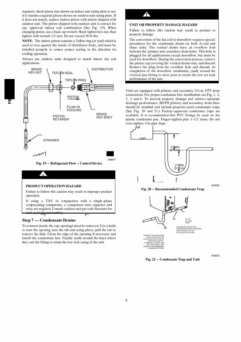
required, check piston size shown on indoor unit rating plate to seeif it matches required piston shown on outdoor unit rating plate. If it does not match, replace indoor piston with piston shipped withoutdoor unit. The piston shipped with outdoor unit is correct forany approved indoor coil combination (See Fig. 19). Whenchanging piston, use a back--up wrench. Hand tighten hex nut, thentighten with wrench 1/2 turn. Do not exceed 30 ft--lbs.
NOTE: The indoor piston contains a Teflon ring (or seal) which is
used to seat against the inside of distributor body, and must be
installed properly to ensure proper seating in the direction for
cooling operation.
Always use outdoor units designed to match indoor fan coilapplications.
TEFLON SEAL
BRASS
HEX NUT
STRAINER
PISTON
RETAINER
BRASS
HEX BODY
DISTRIBUTOR
PISTON
FLOW IN
COOLING
TEFLON RING
A09677
Fig. 19 -- Refrigerant Flow -- Control Device
PRODUCT OPERATION HAZARD
Failure to follow this caution may result in improper productoperation.
If using a TXV in conjunction with a single--phasereciprocating compressor, a compressor start capacitor andrelay are required. Consult outdoor unit pre--sale literature forstart assist kit part number.
CAUTION!
Step 7 — Condensate Drains
To connect drains, the cap openings must be removed. Use a knifeto start the opening near the tab and using pliers, pull the tab toremove the disk. Clean the edge of the opening if necessary and
install the condensate line. Finally caulk around the lines wherethey exit the fitting to retain the low leak rating of the unit.
UNIT OR PROPERTY DAMAGE HAZARD
Failure to follow this caution may result in product orproperty damage.
The conversion of the fan coil to downflow requires specialprocedures for the condensate drains on both A--coil andslope units. The vertical drains have an overflow holebetween the primary and secondary drain holes. This hole isplugged for all applications except downflow, but must be
used for downflow. During the conversion process, removethe plastic cap covering the vertical drains only and discard.Remove the plug from the overflow hole and discard. Atcompletion of the downflow installation, caulk around thevertical pan fitting to door joint to retain the low air leakperformance of the unit.
CAUTION!
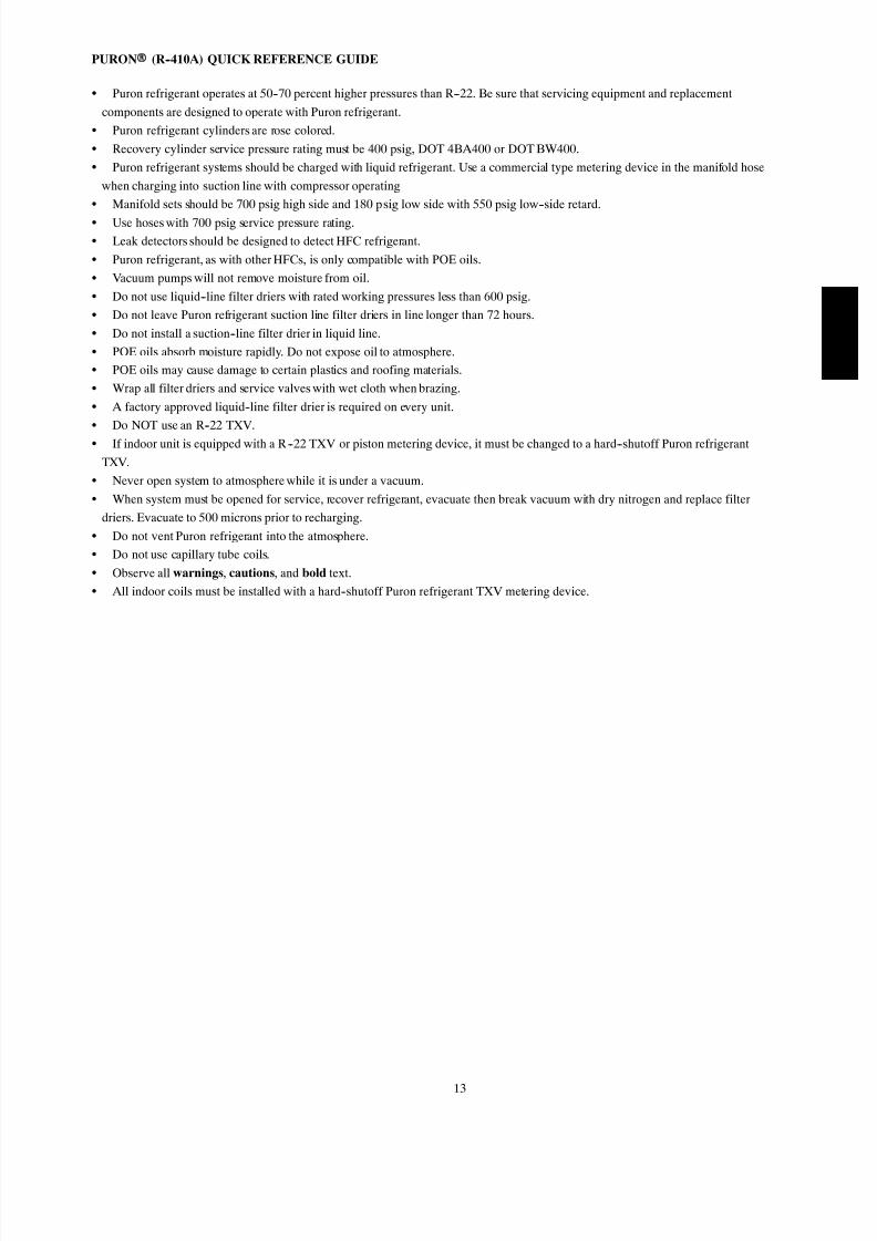
Units are equipped with primary and secondary 3/4--in. FPT drainconnections. For proper condensate line installations see Fig. 1, 2,3, 5 and 6. To prevent property damage and achieve optimumdrainage performance, BOTH primary and secondary drain linesshould be installed and include properly--sized condensate traps.(See Fig. 20 and 21.) Factory--approved condensate traps areavailable. It is recommended that PVC fittings be used on the
plastic condensate pan. Finger--tighten plus 1--1/2 turns. Do notover--tighten. Use pipe dope.
2” MIN(51 mm)
UNIT
2” MIN(51 mm)
A03002
Fig. 20 -- Recommended Condensate Trap
FILTER ACCESSPANEL
SECONDARY DRAIN WITH APPROPRIATE TRAP REQUIRED(USE FACTORY KIT ORFIELD-SUPPLIED TRAP)
PRIMARY TRAP REQUIRED(USE FACTORY KIT OR
FIELD-SUPPLIED TRAP OFSUFFICIENT DEPTH.STANDARD P-TRAPS ARE
NOT SUFFICIENT. SEEFIGURE OF RECOMMENDED
CONDENSATE TRAP)
A03003
Fig. 21 -- Condensate Trap and Unit
F B 4 C
/ F Y 5 B

8/13/2019 FB4C Manual de Instalación
http://slidepdf.com/reader/full/fb4c-manual-de-instalacion 9/14
9
PROPERTY DAMAGE HAZARD
Failure to follow this caution may result in product orproperty damage.
Shallow running traps are inadequate and DO NOT allowproper condensate drainage. (See Fig. 22.)
CAUTION!
DO NOT USE SHALLOW RUNNING TRAPS!
A03013
Fig. 22 -- Insufficient Condensate Trap
NOTE: When connecting condensate drain lines, avoid blocking
filter access panel, thus preventing filter removal. After connection,
prime both primary and secondary condensate traps.
NOTE: If unit is located in or above a living space where damagemay result from condensate overflow, a field--supplied, external
condensate pan should be installed underneath the entire unit, and a
secondary condensate line (with appropriate trap) should be run
from the unit into the pan. Any condensate in this external
condensate pan should be drained to a noticeable place. As an
alternative to using an external condensate pan, some localities
may allow the use of a separate 3/4--in (19 mm) condensate line
(with appropriate trap) to a place where the condensate will be
noticeable. The owner of the structure must be informed that when
condensate flows from the secondary drain or external condensate
pan, the unit requires servicing or water damage will occur.
Install traps in the condensate lines as close to the coil as possible.(See Fig. 21.) Make sure that the outlet of each trap is below its
connection to the condensate pan to prevent condensate fromoverflowing the drain pan. Prime all traps, test for leaks, andinsulate traps if located above a living area. Condensate drain linesshould be pitched downward at a minimum slope of 1--in (25 mm)for every 10--ft (3 m) of length. Consult local codes for additionalrestrictions or precautions.
Step 8 — Accessories
A. Electronic Air Cleaner
The Electronic Air Cleaner may be connected to fan coil as shownin Fig. 23. This method requires a field supplied transformer. SeeElectronic Air Cleaner literature for kit requirements.
RFAN RELAY
NO230VACCOM
NC
NONCSPTWIRENUT
TOBLOWERMOTOR
CONVERSION KITTRANSFORMER
FROM MOLEXPLUG AND
TRANSFORMER(IN UNIT)
TO EAC
208/230VAC COM
24VAC
COM 208/ 230
COM
CONTROL BOARD
G T C C C
A03011
Fig. 23 -- Wiring Layout of Electronic Air Cleaner to Fan Coil
for FY5B Models Only

8/13/2019 FB4C Manual de Instalación
http://slidepdf.com/reader/full/fb4c-manual-de-instalacion 10/14
10
B. Humidifier
Connect humidifier and humidistat to fan coil unit as shown in Fig.24 and Fig. 25. The cooling lockout relay is optional.
R
G
C
E
L
O
Y
THERMOSTAT
RR
C
O
Y
G
C
W2
W2
W2
W3
E
FAN COIL(CONTROL) HEAT PUMP
(CONTROL)
RED
GRY
BRN
WHT
WHT BLU
VIO
HUMIDISTAT
RELAYFAN HUMIDIFIER
115V M
A95294
Fig. 24 -- Wiring Layout of Humidifier to Heat Pump
R
G
W
Y
THERMOSTAT
R
G
W2
W3
E
C
FAN COIL(CONTROL)
C
Y
AIR COND.
HUMIDISTAT
FAN HUMIDIFIER
115V
RED
GRY
WHT
WHTBLU
VIO
BRN
M
A95295
Fig. 25 -- Wiring Layout of Humidifier to Fan Coil
With Electric Heat
Step 9 — Sequence of Operation
A. Continuous Fan
Thermostat closes R to G. G energizes fan relay on PCB whichcompletes circuit to indoor blower motor. When G is de--energized,there is a 90--sec delay before relay opens.
B. Cooling Mode
Thermostat energizes R to G, R to Y, and R to O (heat pump only).G energizes fan relay on PCB which completes circuit to indoorblower motor. When G is de--energized, there is a 90--sec delaybefore fan relay opens.
C. Heat Pump Heating with Auxiliary Electric Heat
Thermostat energizes R to G, R to Y, and R to W. G energizes fanrelay on PCB which completes circuit to indoor blower motor. Wenergizes electric heat relay(s) which completes circuit to heaterelement(s). When W is de--energized, electric heat relay(s) open,turning off heater elements. When G is de--energized there is a90--sec delay before fan relay opens.
D. Electric Heat or Emergency Heat Mode
Thermostat closes R to W. W energizes electric heat relay(s) whichcompletes circuit to heater element(s). Blower motor is energizedthrough normally closed contacts on fan relay. When W isde--energized, electric heat relay(s) opens.
START--UP PROCEDURES
Refer to outdoor unit Installation Instructions for system start--up
instructions and refrigerant charging method details.
UNIT COMPONENT HAZARD
Failure to follow this caution may result in product damage.
Never operate unit without a filter. Damage to blower motoror coil may result. Factory authorized filter kits must be used
when locating the filter inside the unit. For those applications where access to an internal filter is impractical, afield--supplied filter must be installed in the return ductsystem.
CAUTION!
CARE AND MAINTENANCETo continue high performance and minimize possible equipmentfailure, it is essential that periodic maintenance be performed onthis equipment. Consult your local dealer as to the properfrequency of maintenance contract.
The ability to properly perform maintenance on this equipmentrequires certain mechanical skills and tools. If you do not possessthese, contact your dealer for maintenance. The only consumerservice recommended or required is filter replacement or cleaningon a monthly basis.
F B 4 C
/ F Y 5 B

8/13/2019 FB4C Manual de Instalación
http://slidepdf.com/reader/full/fb4c-manual-de-instalacion 11/14
11
AIRFLOW PERFORMANCE TABLES
Table 1 – FB4C Airflow Performance (CFM)
MODEL & SIZE BLOWER SPEED 0.10 0.20 0.30 0.40 0.50 0.60
FB4C 018
Tap 5 767 739 702 669 620 565
Tap 4 614 569 534 486 436 398
Tap 3 701 660 616 581 537 499
Tap 2 614 569 534 486 436 398
Tap 1 614 569 534 486 436 398
FB4C 024
Tap 5 969 936 892 835 763 676
Tap 4 826 795 766 743 706 660
Tap 3 826 795 766 743 706 660Tap 2 701 660 616 581 537 499
Tap 1 617 592 552 507 472 420
FB4C 030
Tap 5 1108 1090 1065 1034 1009 974
Tap 4 1026 1000 969 938 899 865
Tap 3 1026 1000 969 938 899 865
Tap 2 909 873 842 799 762 724
Tap 1 825 795 757 722 674 634
FB4C 036
Tap 5 1301 1276 1245 1218 1176 1121
Tap 4 1227 1191 1169 1143 1105 1074
Tap 3 1227 1191 1169 1143 1105 1074
Tap 2 1087 1062 1030 1001 966 930
Tap 1 1026 1000 969 938 899 865
FB4C 042
Tap 5 1560 1544 1507 1464 1424 1358
Tap 4 1419 1397 1358 1320 1279 1239
Tap 3 1419 1397 1358 1320 1279 1239
Tap 2 1249 1220 1184 1142 1093 1052
Tap 1 1242 1205 1158 1110 1069 1026
FB4C 048
Tap 5 1743 1712 1679 1642 1610 1574
Tap 4 1669 1634 1599 1564 1531 1499
Tap 3 1669 1634 1599 1564 1531 1499
Tap 2 1452 1413 1377 1339 1308 1271
Tap 1 1300 1256 1221 1182 1142 1101
FB4C 060
Tap 5 1897 1867 1836 1808 1774 1736
Tap 4 1817 1785 1757 1724 1693 1655
Tap 3 1817 1785 1757 1724 1693 1655
Tap 2 1657 1621 1589 1557 1518 1474
Tap 1 1443 1412 1377 1332 1286 1243
Table 2 – FY5B Airflow Performance (CFM)MODEL &
SIZEBLOWER
SPEED
0.10 0.20 0.30 0.40 0.50 0.60
208V 230V 208V 230V 208V 230V 208V 230V 208V 230V 208V 230V
FY5B 018 High 742 825 707 768 642 714 568 648 466 526 403 434
Low 541 608 480 564 417 511 357 431 299 363 n/a 304
FY5B 024 High 1041 1112 969 1030 888 936 774 791 573 654 341 438
Low 874 1014 838 953 781 868 684 740 506 573 341 418
FY5B 030 High 1256 1327 1186 1242 1071 1132 952 1005 704 791 459 482
Low 965 1117 949 1074 916 1019 805 902 575 637 396 447
FY5B 036 High 1306 1 490 1 264 1 418 1207 1 338 1 135 1 241 1 043 1 127 842 937
Low 1164 1335 1144 1290 1108 1226 1052 1148 970 1048 697 855
FY5B 042 High 1723 1768 1639 1681 1544 1576 1435 1465 1309 1340 1144 1182
Low 1387 1543 1358 1488 1311 1410 1237 1315 1137 1200 997 1047
FY5B 048 High 1902 1941 1803 1867 1706 1767 1593 1648 1472 1512 1303 1371
Low 1671 1777 1630 1711 1563 1630 1479 1528 1370 1412 1218 1266
FY5B 060
High 2064 2128 1989 2050 1906 1965 1819 1875 1725 1778 1624 1674
Medium 1812 1959 1756 1898 1692 1829 1619 1750 1538 1663 1449 1566
Low 1556 1748 1521 1709 1477 1659 1422 1598 1357 1525 1283 1442
--- Airflow outside 450 cfm/ton.
NOTES:
1. Airflow based upon dry coil at 230v with factory--approved filter and electric heater (2 element heater sizes 018 through 036, 3 elementheater sizes 042 through 060). For FB4C models, airflow at 208 volts is approximately the same as 230 volts because the X13 motor is aconstant torque motor. The torque doesn’t drop off at the speeds the motor operates.
2. To avoid potential for condensate blowing out of drain pan prior to making drain trap:Return static pressure must be less than 0.40 in. wc.Horizontal applications of 042 -- 060 sizes must have supply static greater than 0.20 in. wc.
3. Airflow above 400 cfm/ton on 048 --060 size could result in condensate blowing off coil or splashing out of drain pan.

8/13/2019 FB4C Manual de Instalación
http://slidepdf.com/reader/full/fb4c-manual-de-instalacion 12/14
12
AIRFLOW PERFORMANCE TABLES (cont.)
Table 3 – FB4C Air Delivery Performance Correction Component Pressure Drop (in. wc) at Indicated Airflow (Dry to Wet Coil)
UNIT SIZE CFM
500 600 700 800 900 1000 1100 1200 1300 1400 1500 1600 1700 1800 1900 2000
018 0.034 0.049 0.063 --- --- --- --- --- --- --- --- --- --- --- --- --- --- --- --- --- --- --- --- --- --- --- --- --- ---
024 0.034 0.049 0.063 0.076 0.089 --- --- --- --- --- --- --- --- --- --- --- --- --- --- --- --- --- --- --- --- --- ---
030 --- --- --- --- --- --- 0.049 0.059 0.070 0.080 --- --- --- --- --- --- --- --- --- --- --- --- --- --- --- --- --- ---
036 --- --- --- --- --- --- --- --- --- --- 0.070 0.080 0.090 0.099 --- --- --- --- --- --- --- --- --- --- --- --- --- ---
042 --- --- --- --- --- --- --- --- --- --- --- --- --- --- 0.049 0.056 0.063 0.070 --- --- --- --- --- --- --- --- --- ---
048 --- --- --- --- --- --- --- --- --- --- --- --- --- --- --- --- --- --- 0.063 0.070 0.076 0.083 0.090 --- --- --- ---
060 --- --- --- --- --- --- --- --- --- --- --- --- --- --- --- --- --- --- --- --- --- --- 0.049 0.054 0.059 0.065 0.070
Table 4 – FY5B Air Delivery Performance Correction Component Pressure Drop (in. wc) at Indicated Airflow (Dry to Wet Coil)
UNIT SIZE CFM
500 600 700 800 900 1000 1100 1200 1300 1400 1500 1600 1700 1800 1900 2000
018 0.016 0.027 0.038 --- --- --- --- --- --- --- --- --- --- --- --- --- --- --- --- --- --- --- --- --- --- --- --- --- ---
024 0.016 0.027 0.038 0.049 0.059 --- --- --- --- --- --- --- --- --- --- --- --- --- --- --- --- --- --- --- --- --- ---
030 --- --- --- --- --- --- 0.036 0.046 0.055 0.064 --- --- --- --- --- --- --- --- --- --- --- --- --- --- --- --- --- ---
036 --- --- --- --- --- --- --- --- --- --- 0.055 0.064 0.073 0.081 --- --- --- --- --- --- --- --- --- --- --- --- --- ---
042 --- --- --- --- --- --- --- --- --- --- --- --- --- --- 0.049 0.056 0.063 0.070 --- --- --- --- --- --- --- --- --- ---
048 --- --- --- --- --- --- --- --- --- --- --- --- --- --- --- --- --- --- 0.038 0.043 0.049 0.054 0.059 --- --- --- ---
060 --- --- --- --- --- --- --- --- --- --- --- --- --- --- --- --- --- --- --- --- --- --- 0.031 0.036 0.040 0.044 0.049
Table 5 – FB4C Electric Heater Static Pressure Drop (in. wc)
UNIT SIZE CFM
400 600 800 1000 1200 1400 1600 1800 2000018, 024 0.020 0.044 0.075 --- --- --- --- --- --- --- --- --- --- --- ---
030, 036 --- --- --- --- 0.048 0.072 0.100 --- --- --- --- --- --- --- ---
042, 048, 060 --- --- --- --- --- --- --- --- 0.070 0.092 0.120 0.152 --- ---
Table 6 – FY5B Electric Heater Static Pressure Drop (in. wc)
UNIT SIZE CFM
400 600 800 1000 1200 1400 1600 1800 2000
018, 024 0.020 0.044 0.075 0.110 0.100 --- --- --- --- --- --- --- ---
030, 036, 042 --- --- --- --- 0.048 0.072 0.100 0.130 0.120 --- --- --- ---
048, 060 --- --- --- --- --- --- --- --- --- --- 0.092 0.120 0.152 0.187
Table 7 – Electric Heater Static Pressure Drop (in. wc)
FB4C, FY5B018 --- 036
FB4C, FY5B042 --- 060
HEATERELEMENTS
kWEXTERNAL STATIC
PRESSURECORRECTION
HEATERELEMENTS
kWEXTERNAL STATIC
PRESSURECORRECTION
0 0 +.02 0 0 +.04
1 3, 5 +.01 2 8, 10 +.02
2 8, 10 0 3 9, 15 0
3 9, 15 –.02 4 20 –.02
4 20 –.04 6 18, 24, 30 –.10
F B 4 C
/ F Y 5 B
8/13/2019 FB4C Manual de Instalación
http://slidepdf.com/reader/full/fb4c-manual-de-instalacion 13/14
13
PURON (R--410A) QUICK REFERENCE GUIDE
S Puron refrigerant operates at 50--70 percent higher pressures than R--22. Be sure that servicing equipment and replacement
components are designed to operate with Puron refrigerant.
S Puron refrigerant cylinders are rose colored.
S Recovery cylinder service pressure rating must be 400 psig, DOT 4BA400 or DOT BW400.
S Puron refrigerant systems should be charged with liquid refrigerant. Use a commercial type metering device in the manifold hose
when charging into suction line with compressor operating
S Manifold sets should be 700 psig high side and 180 psig low side with 550 psig low--side retard.
S Use hoses with 700 psig service pressure rating.
S Leak detectors should be designed to detect HFC refrigerant.
S Puron refrigerant, as with other HFCs, is only compatible with POE oils.
S Vacuum pumps will not remove moisture from oil.
S Do not use liquid--line filter driers with rated working pressures less than 600 psig.
S Do not leave Puron refrigerant suction line filter driers in line longer than 72 hours.
S Do not install a suction--line filter drier in liquid line.
S POE oils absorb moisture rapidly. Do not expose oil to atmosphere.
S POE oils may cause damage to certain plastics and roofing materials.
S Wrap all filter driers and service valves with wet cloth when brazing.
S A factory approved liquid--line filter drier is required on every unit.
S Do NOT use an R--22 TXV.
S If indoor unit is equipped with a R --22 TXV or piston metering device, it must be changed to a hard--shutoff Puron refrigerant
TXV.
S Never open system to atmosphere while it is under a vacuum.
S When system must be opened for service, recover refrigerant, evacuate then break vacuum with dry nitrogen and replace filter
driers. Evacuate to 500 microns prior to recharging.
S Do not vent Puron refrigerant into the atmosphere.
S Do not use capillary tube coils.
S Observe all warnings, cautions, and bold text.
S All indoor coils must be installed with a hard--shutoff Puron refrigerant TXV metering device.

8/13/2019 FB4C Manual de Instalación
http://slidepdf.com/reader/full/fb4c-manual-de-instalacion 14/14
Copyright 2010 CAC / BDP D 7310 W. Morris St. D Indianapolis, IN 46231 Printed in U.S.A. Edition Date: 04/10
Manufacturer reserves the right to change, at any time, specifications and designs without notice and without obligations.
Catalog No: IM---FB4C NF---0 2
Replaces: IM---F B4CNF---01
F B 4 C
/ F Y 5 B