fb400/fb900 instruction manual - rkc instrument inc. · . manual manual numberremarks fb400/fb900...
TRANSCRIPT

FB400/FB900
Instruction Manual
Digital Controller
IMR01W03-E9RKC INSTRUMENT INC.

All Rights Reserved, Copyright 2005, RKC INSTRUMENT INC.
Modbus is a registered trademark of Schneider Electric. Company names and product names used in this manual are the trademarks or registered trademarks of
the respective companies.

IMR01W03-E9 i-1
Thank you for purchasing this RKC product. In order to achieve maximum performance and ensure proper operation of your new instrument, carefully read all the instructions in this manual. Please place the manual in a convenient location for easy reference.
NOTICE This manual assumes that the reader has a fundamental knowledge of the principles of electricity,
process control, computer technology and communications.
The figures, diagrams and numeric values used in this manual are only for purpose of illustration.
RKC is not responsible for any damage or injury that is caused as a result of using this instrument, instrument failure or indirect damage.
RKC is not responsible for any damage and/or injury resulting from the use of instruments made by imitating this instrument.
Periodic maintenance is required for safe and proper operation of this instrument. Some components have a limited service life, or characteristics that change over time.
Every effort has been made to ensure accuracy of all information contained herein. RKC makes no warranty expressed or implied, with respect to the accuracy of the information. The information in this manual is subject to change without prior notice.
No portion of this document may be reprinted, modified, copied, transmitted, digitized, stored, processed or retrieved through any mechanical, electronic, optical or other means without prior written approval from RKC.
An external protection device must be installed if failure of this instrument
could result in damage to the instrument, equipment or injury to personnel.
All wiring must be completed before power is turned on to prevent electric shock, fire or damage to instrument and equipment.
This instrument must be used in accordance with the specifications to prevent fire or damage to instrument and equipment.
This instrument is not intended for use in locations subject to flammable or explosive gases.
Do not touch high-voltage connections such as power supply terminals, etc. to avoid electric shock.
RKC is not responsible if this instrument is repaired, modified or disassembled by other than factory-approved personnel. Malfunction can occur and warranty is void under these conditions.
WARNING!

IMR01W03-E9 i-2
This product is intended for use with industrial machines, test and measuring equipment.
(It is not designed for use with medical equipment and nuclear energy.)
This is a Class A instrument. In a domestic environment, this instrument may cause radio interference, in which case the user may be required to take additional measures.
This instrument is protected from electric shock by reinforced insulation. Provide reinforced insulation between the wire for the input signal and the wires for instrument power supply, source of power and loads.
Be sure to provide an appropriate surge control circuit respectively for the following: - If input/output or signal lines within the building are longer than 30 meters. - If input/output or signal lines leave the building, regardless the length.
This instrument is designed for installation in an enclosed instrumentation panel. All high-voltage connections such as power supply terminals must be enclosed in the instrumentation panel to avoid electric shock by operating personnel.
All precautions described in this manual should be taken to avoid damage to the instrument or equipment.
All wiring must be in accordance with local codes and regulations.
All wiring must be completed before power is turned on to prevent electric shock, instrument failure, or incorrect action. The power must be turned off before repairing work for input break and output failure including replacement of sensor, contactor or SSR, and all wiring must be completed before power is turned on again.
To prevent instrument damage or failure, protect the power line and the input/output lines from high currents with a protection device such as fuse, circuit breaker, etc.
Prevent metal fragments or lead wire scraps from falling inside instrument case to avoid electric shock, fire or malfunction.
Tighten each terminal screw to the specified torque found in the manual to avoid electric shock, fire or malfunction.
For proper operation of this instrument, provide adequate ventilation for heat dispensation.
Do not connect wires to unused terminals as this will interfere with proper operation of the instrument.
Turn off the power supply before cleaning the instrument.
Do not use a volatile solvent such as paint thinner to clean the instrument. Deformation or discoloration will occur. Use a soft, dry cloth to remove stains from the instrument.
To avoid damage to instrument display, do not rub with an abrasive material or push front panel with a hard object.
Do not connect modular connectors to telephone line.
When high alarm with hold action/re-hold action is used for Event function, alarm does not turn on while hold action is in operation. Take measures to prevent overheating which may occur if the control device fails.
FOR PROPER DISPOSAL
When disposing of each part used for this instrument, always follows the procedure for disposing of industrial wastes stipulated by the respective local community.
CAUTION

IMR01W03-E9 i-3
SYMBOLS
Safety Symbols:
: This mark indicates important information on installation, handling and operating procedures.
: This mark indicates supplemental information on installation, handling and operating procedures.
: This mark indicates where additional information may be located.
Character Symbols:
0 1 2 3 4 5 6 7 8 9 Minus Period
A B (b) C c D (d) E F G H I J K
L M N (n) O (o) P Q (q) R (r) S T t U u
V W X Y Z Degree / Dash
CAUTION
: This mark indicates precautions that must be taken if there is danger of electric shock, fire, etc., which could result in loss of life or injury.
: This mark indicates that if these precautions and operating procedures are not
taken, damage to the instrument may result.
: This mark indicates that all precautions should be taken for safe usage.
WARNING
!
Dim lighting
Bright lighting
Flashing

IMR01W03-E9 i-4
DOCUMENT CONFIGURATION
There are six manuals pertaining to this product. Please be sure to read all manuals specific to your application requirements. If you do not have a necessary manual, please contact RKC sales office, the agent, or download from the official RKC website.
The following manuals can be downloaded from the official RKC website: http://www.rkcinst.com/english/manual_load.htm.
Manual Manual Number Remarks
FB400/FB900 Installation Manual IMR01W01-E This manual is enclosed with instrument. This manual explains the mounting and wiring, front panel name, and the operation mode outline.
FB400/FB900 Quick Operation Manual
IMR01W02-E This manual is enclosed with instrument. This manual explains the basic key operation, mode menu, and data setting.
FB400/FB900 Parameter List IMR01W06-E This manual is enclosed with instrument. This list is a compilation of the parameter data of each mode.
FB400/FB900 Communication Quick Manual
IMR01W07-E A product box contains this manual. (Only FB400/900 provided with the communication function) This manual explains the connection method with host computer, communication parameters, and communication data (except for parameters in Engineering Mode).
FB400/FB900 Instruction Manual IMR01W03-E9 This Manual. This manual explains the method of the mounting and wiring, the operation of various functions, and troubleshooting.
FB100/FB400/FB900 Communication Instruction Manual *
IMR01W04-E This manual explains RKC communication protocol (ANSI X3.28-1976), Modbus, and relating to the communication parameters setting.
* Sold separately
Read this manual carefully before operating the instrument. Please place this manual in a convenient location for easy reference.

IMR01W03-E9 i-5
CONTENTS
Page
1. OUTLINE ........................................................................... 1-1
1.1 Features ....................................................................................................... 1-2
1.2 Checking the Product ................................................................................... 1-3
1.3 Model Code .................................................................................................. 1-4 Suffix code .............................................................................................................. 1-4 Quick start code 2 (Initial setting code) .................................................................. 1-6
1.4 Parts Description .......................................................................................... 1-7
1.5 Input/Output Functions ............................................................................... 1-11 2. HANDLING PROCEDURE TO OPERATION .................... 2-1 3. MOUNTING ........................................................................ 3-1
3.1 Mounting Cautions ........................................................................................ 3-2
3.2 Dimensions ................................................................................................... 3-3 FB400 ..................................................................................................................... 3-3 FB900 ..................................................................................................................... 3-3
3.3 Procedures of Mounting and Removing ....................................................... 3-4 Mounting procedures .............................................................................................. 3-4 Removing procedures ............................................................................................ 3-4
4. WIRING .............................................................................. 4-1
4.1 Wiring Cautions ............................................................................................ 4-2
4.2 Terminal Layout ............................................................................................ 4-5 FB400 ..................................................................................................................... 4-5 FB900 ..................................................................................................................... 4-5 Isolations of input and output (common to FB400/900) .......................................... 4-6
4.3 Wiring of Each Terminal ............................................................................... 4-7 Power supply .......................................................................................................... 4-7 Output 1 (OUT1)/Output 2 (OUT2) ......................................................................... 4-8 Digital output 1 to 4 (DO1 to DO4) [optional] .......................................................... 4-9 Transmission output (AO) [optional] ..................................................................... 4-10 Measured input (Thermocouple/RTD/Voltage/Current) [universal input] .............. 4-10 Remote setting (RS) input [universal input] .......................................................... 4-11 Digital input (DI1 to DI4 [optional], DI5 to DI7 [standard]) .................................... 4-11 Current transformer (CT) input/Power feed forward (PFF) input/ Feedback resistance (FBR) input [optional] ......................................................... 4-12 Communication 1/Communication 2 [optional] ..................................................... 4-12

IMR01W03-E9 i-6
Page
4.4 Handling of the Terminal Cover [optional] .................................................. 4-15 Mounting procedures ............................................................................................ 4-15 Removing procedures .......................................................................................... 4-16
5. OPERATION MENU AND BASIC OPERATION ............... 5-1
5.1 Operation Menu ............................................................................................ 5-2 Input type and input range display .......................................................................... 5-3
5.2 Basic Operation ............................................................................................ 5-4 5.2.1 Scrolling through parameters ............................................................................ 5-4 SV setting & monitor mode ................................................................................. 5-4 Parameter setting mode, Setup setting mode .................................................... 5-5 Operation mode .................................................................................................. 5-6 Engineering mode ............................................................................................... 5-7
5.2.2 Changing Set value (SV) ................................................................................... 5-8 5.2.3 Operation of the direct keys .............................................................................. 5-9 5.2.4 Data lock function ............................................................................................ 5-10
6. OPERATION ...................................................................... 6-1
6.1 Operating Precautions .................................................................................. 6-2
6.2 Monitoring Display in Operation .................................................................... 6-3 Direct key type 1 ..................................................................................................... 6-3 Direct key type 2 ..................................................................................................... 6-4
6.3 Operating Setting .......................................................................................... 6-5 6.3.1 Set the Set value (SV) ....................................................................................... 6-5 6.3.2 Set the Event set value (alarm set value) ......................................................... 6-6 6.3.3 Autotuning (AT) start ......................................................................................... 6-8 To manually set PID values ................................................................................ 6-9
6.4 RUN/STOP Transfer ................................................................................... 6-11 RUN/STOP transfer by Front key operation ......................................................... 6-11 RUN/STOP transfer by Direct key (R/S) operation ............................................... 6-12 RUN/STOP transfer by Digital input (DI) .............................................................. 6-13
6.5 Autotuning (AT) .......................................................................................... 6-15 Caution for using the Autotuning (AT) .................................................................. 6-15 Requirements for Autotuning (AT) start ................................................................ 6-15 Requirements for Autotuning (AT) cancellation .................................................... 6-15 Autotuning (AT) start/stop operation ..................................................................... 6-16
6.6 Startup Tuning (ST) .................................................................................... 6-18 Caution for using the Startup tuning (ST) ............................................................. 6-18 Requirements for Startup tuning (ST) start ........................................................... 6-19

IMR01W03-E9 i-7
Page Requirements for Startup tuning (ST) cancellation ............................................... 6-19 Startup tuning (ST) setting .................................................................................... 6-20
6.7 Auto/Manual Transfer ................................................................................. 6-23 Auto/Manual transfer by Front key operation ....................................................... 6-24 Auto/Manual transfer by Ddirect key (A/M) operation ........................................... 6-25 Auto/Manual transfer by Digital input (DI) ............................................................. 6-26 Procedure for setting the Manipulated output value (MV) in Manual mode .......... 6-27
6.8 Remote/Local Transfer ............................................................................... 6-28 Remote/Local transfer by Front key operation ..................................................... 6-28 Remote/Local transfer by Direct key (R/L) operation ........................................... 6-29 Remote/Local transfer by Digital input (DI) ........................................................... 6-30
6.9 Control Area Transfer ................................................................................. 6-32 Control area transfer by Front key operation ........................................................ 6-33 Control area transfer by Direct key (AREA) operation .......................................... 6-34 Control area transfer by Digital input (DI) [optional] ............................................. 6-35 Control area transfer by Area soak time (Ramp/Soak Control) ............................ 6-35
6.10 Interlock Release ...................................................................................... 6-36 Interlock release method by Front key operation ................................................. 6-37 Interlock release method by Digital input (DI) ....................................................... 6-38
6.11 Start Action at Recovering Power Failure ................................................. 6-39 Hot/Cold start selection ........................................................................................ 6-39 Start determination point ...................................................................................... 6-39
6.12 Position Proportioning PID Control ........................................................... 6-40 Setting flowchart ................................................................................................... 6-42 Setting procedures ............................................................................................... 6-44
6.13 Ramp/Soak Control .................................................................................. 6-50 Operation flowchart .............................................................................................. 6-51 Settings before operation ..................................................................................... 6-52 Operation procedures ........................................................................................... 6-55
6.14 Group Operation by the Intercontroller Communication ........................... 6-60 6.14.1 Wiring method of the Intercontroller communication ..................................... 6-60 6.14.2 Common setting of the Intercontroller communication .................................. 6-61 6.14.3 Group RUN/STOP function ........................................................................... 6-63 Operation flowchart ........................................................................................... 6-63 Requirements for Group RUN/STOP ................................................................ 6-64 Group RUN/STOP operation and states ........................................................... 6-64 Settings before operation .................................................................................. 6-65 Usage example ................................................................................................. 6-69
6.14.4 Automatic temperature rise function (with learning function) ........................ 6-72 Requirements for automatic temperature rise learning start ............................. 6-73 Requirements for automatic temperature rise learning cancellation ................. 6-73

IMR01W03-E9 i-8
Page Requirements for automatic temperature rise start .......................................... 6-74 Requirements for automatic temperature rise cancellation .............................. 6-74 Operation flowchart ........................................................................................... 6-75 Settings before operation .................................................................................. 6-76 Operation procedures ....................................................................................... 6-80
6.14.5 Cascade control function ............................................................................... 6-82 Operation flowchart ........................................................................................... 6-83 Settings before operation .................................................................................. 6-84 Adjustment after control starting ....................................................................... 6-87 Operation procedures ....................................................................................... 6-90
6.14.6 Ratio setting function ..................................................................................... 6-91 Operation flowchart ........................................................................................... 6-92 Settings before operation .................................................................................. 6-93 Adjustment after control starting ....................................................................... 6-96 Operation procedures ....................................................................................... 6-99 Usage example ............................................................................................... 6-100
7. DESCRIPTION OF EACH PARAMETER .......................... 7-1
7.1 SV Setting & Monitor Mode .......................................................................... 7-2 7.1.1 Display sequence (When the Direct key type is Type 1) ................................... 7-2 7.1.2 Display sequence (When the Direct key type is Type 2) ................................... 7-3 7.1.3 Monitor and setting item .................................................................................... 7-4
7.2 Operation Mode .......................................................................................... 7-14 7.2.1 Display sequence ............................................................................................ 7-14 7.2.2 Operation item ................................................................................................. 7-15
7.3 Parameter Setting Mode ............................................................................. 7-19 7.3.1 Display sequence ............................................................................................ 7-20 7.3.2 Parameter setting item .................................................................................... 7-21
7.4 Setup Setting Mode .................................................................................... 7-34 7.4.1 Display sequence ............................................................................................ 7-34 7.4.2 Setup setting item ........................................................................................... 7-35
7.5 Engineering Mode ...................................................................................... 7-48 7.5.1 Display sequence ............................................................................................ 7-48 7.5.2 Precaution against parameter change ............................................................ 7-55 7.5.3 Engineering setting item .................................................................................. 7-62
Function block 10 (F10.) [Display] ................................................................... 7-62 Function block 11 (F11.) [Direct key] ............................................................... 7-67 Function block 21 (F21.) [Input] ....................................................................... 7-69 Function block 22 (F22.) [Remote setting input type] ...................................... 7-77 Function block 23 (F23.) [Digital input assignment] ........................................ 7-78
IMR01W03-E9 i-9
Page Function block 30 (F30.) [Output] .................................................................... 7-79 Function block 33 (F33.) [Transmission output] .............................................. 7-83 Function block 41 (F41.) [Event 1] .................................................................. 7-85 Function block 42 (F42.) [Event 2] .................................................................. 7-95 Function block 43 (F43.) [Event 3] ................................................................ 7-102 Function block 44 (F44.) [Event 4] ................................................................ 7-109 Function block 45 (F45.) [Heater break alarm 1] ........................................... 7-116 Function block 46 (F46.) [Heater break alarm 2] ........................................... 7-120 Function block 50 (F50.) [Hot/Cold start etc.] ................................................ 7-123 Function block 51 (F51.) [Control 1] .............................................................. 7-129 Function block 52 (F52.) [Control 2] .............................................................. 7-146 Function block 53 (F53.) [Position proportioning PID control] ....................... 7-158 Function block 54 (F54.) [Startup tuning] ...................................................... 7-163 Function block 55 (F55.) [Group/Automatic temperature rise] ...................... 7-165 Function block 60 (F60.) [Communication protocol] ...................................... 7-168 Function block 70 (F70.) [Time unit] .............................................................. 7-169 Function block 71 (F71.) [Setting limiter] ....................................................... 7-170 Function block 91 (F91.) [Others] .................................................................. 7-171
8. TROUBLESHOOTING ....................................................... 8-1
8.1 Error Display ................................................................................................. 8-2 Display when input error occurs ............................................................................. 8-2 Self-diagnostic error ............................................................................................... 8-3
8.2 Solutions for Problems ................................................................................. 8-4 Display .................................................................................................................... 8-5 Control .................................................................................................................... 8-6 Operation ................................................................................................................ 8-8 Event function ......................................................................................................... 8-9 Heater break alarm (HBA) .................................................................................... 8-10
9. SPECIFICATIONS ............................................................. 9-1
Measured input ................................................................................................... 9-2 Remote setting (RS) input ................................................................................. 9-3 Current transformer (CT) input [optional] ............................................................ 9-4 Feedback resistance (FBR) input [optional] ........................................................ 9-4 Power feed forward (PFF) input [optional] .......................................................... 9-4 Digital input (DI) .................................................................................................. 9-4 Output (OUT1, OUT2) ........................................................................................ 9-5 Digital output (DO1 to DO4) [optional] ................................................................ 9-6 Transmission output (AO) [optional] ................................................................... 9-6

IMR01W03-E9 i-10
Page Performance (at the ambient temperature 23 ±2 C) .......................................... 9-7 Control ................................................................................................................ 9-8 Brilliant II PID control .......................................................................................... 9-8 Brilliant II Heat/Cool PID control ......................................................................... 9-9 Position proportioning PID control without FBR ................................................ 9-10 Event function [optional] ................................................................................... 9-11 Control loop break alarm (LBA) [optional] ......................................................... 9-12 Power feed forward (PFF) function [optional] ................................................... 9-12 Heater break alarm (HBA) [time-proportional control output (optional)] ........... 9-12 Heater break alarm (HBA) [continuous control output (optional)] ..................... 9-12 Multi-memory area function [optional] ............................................................... 9-12 Loader communication ..................................................................................... 9-13 Communication [optional] ................................................................................. 9-13 Intercontroller communication function [optional] ............................................. 9-14 Self-diagnostic function ..................................................................................... 9-15 Power ................................................................................................................ 9-15 General specifications ...................................................................................... 9-16 Standard ........................................................................................................... 9-17
APPENDIX ............................................................................ A-1
A. Removing the Internal Assembly ................................................................... A-2
B. Replacing the Waterproof/Dustproof Rubber Packing ................................... A-4
C. Transformer Dimensions for Power Feed Forward ....................................... A-6
D. Current Transformer (CT) Dimensions .......................................................... A-7
E. Memory Area Data List ................................................................................. A-8
F. Parameter List ............................................................................................... A-9
G. Seal [for Unit and Direct key type 2] (accessory attached) ......................... A-25 INDEX .................................................................................... B-1
Alphabetical Order ............................................................................................. B-1
Character Order ................................................................................................. B-4 Revisions

OUTLINE
IMR01W03-E9 1-1
1.1 Features ........................................................................................... 1-2
1.2 Checking the Product ....................................................................... 1-3
1.3 Model Code ...................................................................................... 1-4
1.4 Parts Description .............................................................................. 1-7
1.5 Input/Output Functions ................................................................... 1-11

1. OUTLINE
1-2 IMR01W03-E9
1.1 Features
This chapter describes features, package contents and model code, etc. The digital controller of this high performance type has the following features:
Panel space saving: 60 mm depth
Selectable sampling time among 50ms, 100ms, and 250 ms. Selectable sampling time makes the FB Series suitable for any application ranging from pressure control requiring fast response to precise control requiring highest resolution. (Factory setting: 100 ms)
Selectable PID control algorithm PID control algorithm is selectable in the FB Series to achieve the most precise control for various applications. PV derivative PID: suitable for fixed setpoint control (Factory setting) Deviation derivative PID: suitable for ramp control using ramp-to-setpoint function and cascade control.
Advanced Heat/Cool PID algorithm with Undershoot Suppression
Startup tuning to eliminate time for autotuning
Direct Function Keys Three direct function keys enable one-touch operation on frequently used functions such as Auto/Manual, Monitoring display scroll, and Memory area selection. The keys can also be configured as RUN/STOP, Remote/Local, and Auto/Manual keys.
Up to 8 recipes (multi-memory area) or Ramp/Soak control FB Series can store up to 8 sets of control parameters. Ramp/Soak control is available by using the memory area function.
Open Network Connectivity The FB Series can be connected to various Open Networks, such as PROFIBUS, DeviceNet, CC-Link, and Ethernet via a gateway, by using our COM-J Series.
Easy maintenance The internal assembly of the FB Series can be removed from the front.
NEMA4X and IP66 waterproof and dustproof protection for severe environments. (standard)
Two communication ports (optional) Host communication: The FB Series has a first communication port (COM1) to communicate (Host communication) with a computer or operation panel for Host communication. Intercontroller communication: The FB Series has a second communication port (COM2) for Intercontroller communication. It achieves more precise cascade control and ratio control by sending data via digital communication while conventional cascade controllers send data to slave controllers by analog signal with less resolution.
Easy-setup and Data Monitoring via a standard data port The FB Series has the loader port (provided as standard) to connect to a PC USB port with Windows 2000/XP/Vista/7. The standard port allows setup and data logging to be managed by the PC. The FB Series is recognized as an external device on the PC. [The communication tool (WinUCI, PROTEM2) can be downloaded from the RKC official website: http://www.rkcinst.com/.]

1. OUTLINE
IMR01W03-E9 1-3
1.2 Checking the Product
Before using this product, check each of the following:
Model code Check that there are no scratches or breakage in external appearance (case, front panel, or terminal, etc.) Check that all of the items delivered are complete. (Refer to below)
Accessories Q’TY Remarks
Instrument 1
Mounting brackets (with screw) 2 FB900: 4
Seal (SAP-306) 1
Case rubber packing (FB400: KFB400-36<1>, FB900: KFB900-36<1>)
1 For waterproof/dustproof
Installation Manual (IMR01W01-E) 1 Enclosed with instrument
Quick Operation Manual (IMR01W02-E) 1 Enclosed with instrument
Parameter List (IMR01W06-E) 1 Enclosed with instrument
Communication Quick Manual (IMR01W07-E) 1 Enclosed with instrument (with communication 1 function )
Instruction Manual (IMR01W03-E9) 1 This manual (sold separately)
This manual can be downloaded from the official RKC website: http://www.rkcinst.com/english/manual_load.htm. Communication Instruction Manual (IMR01W04-E) 1 Sold separately
Terminal cover (KFB400-58(3)) Depending on the order quantity Optional (sold separately)
Front cover (FB400: KRB400-36, FB900: KRB900-36)
Depending on the order quantity
Optional (sold separately)
Current transformer (CTL-6-P-N [for 0 to 30 A] or CTL-12-S56-10L-N [for 0 to 100 A])
Depending on the order quantity
Optional (sold separately)
Power feed transformer (PFT-01 [100 to 120 V AC] or PFT-02 [200 to 240 V AC])
1 Optional (When ordered PFF function, this transformer is attached.)
ローダツール操作説明書 (IMR01W05-J) 1 別売り
If any of the products are missing, damaged, or if your manual is incomplete, please contact RKC sales office or the agent.

1. OUTLINE
1-4 IMR01W03-E9
1.3 Model Code
Check that the product received is correctly specified by referring to the following model code list: If the product is not identical to the specifications, please contact RKC sales office or the agent.
Suffix code
-□ □-□*□ □ □ □ / □ □-□ □□□ /Y (1) (2) (3) (4) (5) (6) (7) (8) (9) (10) (11) (12)
Suffix code Specifications Hardware coding only Quick start code1
(1) (2) (3) (4) (5) (6) (7) (8) (9) (10) (11) (12)
Relay contact output M
Voltage pulse output V
Output 1 (OUT1) Voltage output, Current output (Refer to Output Code Table)
Triac output T
Open collector output D
None N
Relay contact output M
Output 2 (OUT2) Voltage pulse output V
Voltage output, Current output (Refer to Output Code Table)
Triac output T
Open collector output D
Power supply voltage 24 V AC/DC 3
100 to 240 V AC 4
Digital output (DO1 to DO4) None N
[Relay contact output] DO1 DO2 DO3 DO4 4
CT input None N
Power feed forward (PFF) CT input (2 points) T
input PFF input (one 100-120 V AC transformer included) 1
Feedback resistance input PFF input (one 200-240 V AC transformer included) 2
CT input (1point) PFF input (one 100-120 V AC transformer included) 3
CT input (1point) PFF input (one 200-240 V AC transformer included) 4
Feedback resistance input F
Transmission output (AO) 1 None N
Voltage output, Current output (Refer to Output Code Table)
Communication function 2 None N
Digital input (DI1 to DI4) Communication 1 (RS-232C) No communication 2 1
Communication 1 (RS-422A) No communication 2 4
Communication 1 (RS-485) No communication 2 5
Communication 1 (RS-232C) Communication 2 (RS-485) 3 W
Communication 1 (RS-485) Communication 2 (RS-485) 3 X
No communication 1 Communication 2 (RS-485) 3 Y
Digital input (DI1 to DI4) [for Memory area transformer] D
Case color White case N
Black case A
No quick start code (Configured to factory set value) N
Quick start code Specify quick start code 1 1
Specify quick start code 1 and 2 (Refer to page 1-6) 2
Quick start code 1 is not specified No code
PID control with AT (Reverse action) F
PID control with AT (Direct action) D
Control Method Heat/Cool PID control with AT G
[Quick start code 1] Heat/Cool PID control with AT (for Extruder [air cooling]) A
Heat/Cool PID control with AT (for Extruder [water cooling]) W
Position proportioning PID control without FBR (Reverse action) Z
Position proportioning PID control without FBR (Direct action) C
Measured input and Range Quick start code 1 is not specified No code
[Quick start code 1] Refer to Range Code Table.
Instrument specification Version symbol Y
1 If any one of the transmission outputs is specified (other than the code "N"), the digital inputs (from DI1 to DI4) are automatically added. 2 If any one of the communication functions is also specified (other than the code "N"), the digital inputs (from DI1 to DI4) are automatically added. 3 Factory set value of Communication 2 protocol: Intercontroller communication
FB400 FB900

1.3 Model Code
IMR01W03-E9 1-5
Output Code Table
Output type Code Output type Code
Voltage output (0 to 1 V DC) * 3 Voltage output (1 to 5 V DC) 6
Voltage output (0 to 5 V DC) 4 Current output (0 to 20 mA DC) 7
Voltage output (0 to 10 V DC) 5 Current output (4 to 20 mA DC) 8
* 0 to 1 V DC output can be specified only for transmission output (AO).
Range Code Table [Thermocouple (TC) input, RTD input] [Voltage input, Current input]
Type Code Measured range Code Measured range Type Code Measured range
K35 200.0 to 400.0 C KC4 328.0 to 400.0 F 0 to 10 mV DC 101
K40 200.0 to 800.0 C KC6 250.0 to 800.0 F 0 to 100 mV DC 201
K41 200 to 1372 C KC5 328 to 2502 F 0 to 1 V DC 301
K K09 0.0 to 400.0 C KA4 0.0 to 800.0 F 0 to 5 V DC 401 Programmable range
K10
K14
0.0 to 800.0 C
0 to 300 C
KA1
KA2
0 to 800 F
0 to 1600 F
0 to 10 V DC 501 19999 to 19999
K02 0 to 400 C 1 to 5 V DC 601 [The decimal point position is selectable]
K04 0 to 800 C 0 to 20 mA DC 701 (Factory set value: 0.0 to 100.0)
J27 200.0 to 400.0 C JC6 328.0 to 1200.0 F 4 to 20 mA DC 801
J32 200.0 to 800.0 C JC7 200.0 to 700.0 F 100 to 100 mV DC 901
J15 200 to 1200 C JB9 328 to 2192 F 1 to 1 V DC 902
J J08 0.0 to 400.0 C JB6 0.0 to 800.0 F 10 to 10 mV DC 903
J09 0.0 to 800.0 C JA1 0 to 800 F
J02 0 to 400 C JA2 0 to 1600 F
J04 0 to 800 C
T T19 200.0 to 400.0 C TC2 328.0 to 752.0 F
E E21 200.0 to 700.0 C EA9 328.0 to 1292.0 F
E06 200 to 1000 C EB1 328 to 1832 F
S S06 50 to 1768 C SA7 58 to 3214 F
R R07 50 to 1768 C RA7 58 to 3214 F
B B03 0 to 1800 C BB2 0 to 3272 F
N N02 0 to 1300 C NA7 0 to 3272 F
PLII A02 0 to 1390 C AA2 0 to 2534 F
W5Re/W26Re W03 0 to 2300 C WA2 0 to 4200 F
U U04 0.0 to 600.0 C UB2 32.0 to 1112.0 F
L L04 0.0 to 900.0 C LA9 32.0 to 1652.0 F
Pt100 D34 100.00 to 100.00 C DD1 200.0 to 200.0 F
D21 200.0 to 200.0 C DC8 199.99 to 199.99 F
D35 200.0 to 850.0 C DC9 328.0 to 1562.0 F
JPt100 P29 100.00 to 100.00 C PC8 199.99 to 199.99 F
P30 200.0 to 640.0 C PC9 328.0 to 1184.0 F
PD1 200.0 to 200.0 F

1.3 Model Code
IMR01W03-E9 1-6
Quick start code 2 (Initial setting code)
Quick start code 2 tells the factory to ship with each parameter preset to the values detailed as specified by the customer. Quick start code is not necessarily specified when ordering, unless the preset is requested. These parameters are software selectable items and can be re-programmed in the field via the manual.
□ □-□ □ □ □-□ □ (1) (2) (3) (4) (5) (6) (7) (8)
Specifications Quick start code 2 (Initial setting code) (1) (2) (3) (4) (5) (6) (7) (8)
Output assignment OUT1, OUT2, DO1 to DO4 (Refer to Output Assignment Code Table)
Voltage input (0 to 10 mV DC) 1
Voltage input (0 to 100 mV DC) 2
Voltage input (0 to 1 V DC) 3
Remote setting input * Voltage input (0 to 5 V DC) 4
Voltage input (0 to 10 V DC) 5
Voltage input (1 to 5 V DC) 6
Current input (0 to 20 mA DC) 7
Current input (4 to 20 mA DC) 8
Event function 1 (EV1) None N
Refer to Event Type Code Table
Event function 2 (EV2) None N
Refer to Event Type Code Table
Event function 3 (EV3) None N
Refer to Event Type Code Table
Event function 4 (EV4) None N
Refer to Event Type Code Table
Control loop break alarm (LBA) 5
CT1 (none), CT2 (none) N
CT1 (CTL-6-P-N), CT2 (none) P
CT type CT1 (CTL-12-S56-10L-N), CT2 (none) S
CT1 (CTL-6-P-N), CT2 (CTL-6-P-N) T
CT1 (CTL-12-S56-10L-N), CT2 (CTL-12-S56-10L-N) U
None N
Communication 1 protocol RKC communication (ANSI X3.28-1976) 1
Modbus 2
* Specify "8" when the remote setting input signal is not used. Output Assignment Code Table
Code Output 1 (OUT1) Output 2 (OUT2) Digital output 1 (DO1) Digital output 2 (DO2) Digital output 3 (DO3) Digital output 4 (DO4)
1 Control output 1 Control output 2 Event function 1 (EV1) Event function 2 (EV2) Event function 3 (EV3) Event function 4 (EV4)
2 Control output 1 Control output 2 Event function 1 (EV1) Event function 2 (EV2) Event function 3 (EV3) HBA1, HBA2
3 Control output 1 Control output 2 Event function 1 (EV1) Event function 2 (EV2) HBA1, HBA2 FAIL (De-energized)
4 Control output 1 Control output 2 Event function 1 (EV1) HBA1, HBA2 Event function 3 (EV3) Event function 4 (EV4)
5 Control output 1 HBA1, HBA2 Event function 1 (EV1) Event function 2 (EV2) Event function 3 (EV3) Event function 4 (EV4)
6 Control output 1 HBA1, HBA2 Event function 1 (EV1) Event function 2 (EV2) Event function 3 (EV3) FAIL (De-energized)
7 Control output 1 FAIL (De-energized) Event function 1 (EV1) Event function 2 (EV2) Event function 3 (EV3) Event function 4 (EV4)
Energized/De-energized is configurable except for the FAIL output. (Factory shipment: Energized) An output logic becomes OR output when two or more output functions are assigned to one output. Invalid for a non-existing output/event function. When used as Heat/Cool PID control or Position proportioning PID control, select any code of 1 to 4.
Event Type Code Table
Code Type Code Type Code Type
A Deviation high H Process high V SV high
B Deviation low J Process low W SV low
C Deviation high/low K Process high with hold action 1 MV1 high [heat-side]
D Band L Process low with hold action 2 MV1 low [heat-side]
E Deviation high with hold action Q Deviation high with re-hold action 3 MV2 high [cool-side]
F Deviation low with hold action R Deviation low with re-hold action 4 MV2 low [cool-side]
G Deviation high/low with hold action T Deviation high/low with re-hold action

1. OUTLINE
IMR01W03-E9 1-7
1.4 Parts Description
This section describes various display units and the key functions. Front Panel View
FB400
FB900
Manual (MAN) mode lamp [Green] Remote (REM) mode lamp [Green]
Autotuning (AT) lamp [Green]
Measured value (PV) display Manipulated output (MV) lamp
[Green]
Set value (SV) display
Output (OUT1, OUT2) lamps[Green] Digital output (DO1 to DO4) lamps [Green] Alarm (ALM) lamp [Red]
Memory area display
Bar graph display
Direct keys
Up key
Down key
Set (SET) key
Shift key
Manual (MAN) mode lamp [Green] Remote (REM) mode lamp [Green]
Measured value (PV) display
Memory area display
Bar graph display
Direct keys
Set (SET) key
Shift key
Up key
Down key
Autotuning (AT) lamp [Green]
Manipulated output (MV) lamp [Green]
Set value (SV) display
Output (OUT1, OUT2) lamps [Green]Digital output (DO1 to DO4) lamp [Green] Alarm (ALM) lamp [Red]

1.4 Parts Description
IMR01W03-E9 1-8
Display units
Measured value (PV) display [Green] Displays Measured value (PV) or various parameters’ symbols.
Set value (SV) display [Orange] Displays Set value (SV), Manipulated output value (MV) or various parameters’ set values.
Memory area display [Orange] Displays memory area number (1 to 8). Indication lamps
Manual (MAN) mode lamp [Green] Lights when operated in Manual mode.
Remote (REM) mode lamp [Green] Lights when operated in Remote mode.
Autotuning (AT) lamp [Green] Flashes when Autotuning is activated. (After autotuning is completed: AT lamp will go out)
Manipulated output (MV) lamp [Green]
Lights when operated in Manual mode. In this case, the Set value (SV) display shows the Manipulated output value (MV).
Output (OUT1, OUT2) lamp [Green] Lights when the output corresponding to each lamp is ON. Lamp indication becomes as follows for current output or voltage output:
For an output of less than 0 %: Extinguished For an output of more than 0 % but less than 100 %: Dimly lit For an output of more than 100 %: Lit
Digital output (DO1 to DO4) lamp [Green]
Lights when the output corresponding to each lamp is ON.
Alarm (ALM) lamp [Red] Lights when alarm (Event or Heater break alarm [HBA]) is turned ON. The type of alarm which is on can be checked on the event monitor screen.
These lamps work with event outputs (event function, HBA function, LBA function) which are assigned to OUT, DO and ALM. For assignment of outputs to OUT, DO and ALM, refer to the section 7.5 Engineering Mode (P. 7-48).
Bar graph display [Green] * Manipulated output values (MV1, MV2)
[Factory set value]
Displays the Manipulated output value (MV). When Manipulated output value (MV) is at 0 % or less, the left-end dot of the bar-graph flashes. When MV exceeds 100 %, the right-end dot flashes.
[Example] 0 50 100
Heat/Cool PID control:
When both OUT1 and OUT2 light, this means overlapping, but in this case the bar graph displays only the Manipulated output value (MV1) [heat-side].
Position proportioning PID control:
[With FBR input] Displays the FBR input value (0.0 to 100.0 %). [Without FBR input]
Cannot be used as a bar graph. The bar graph displays the over-scaled state (an output of more than 100 %). In this case, it is recommended to be set to “No display.”
[Example] 0 50 100
Flashing
Measured value (PV) Displays the Measured value (PV). Scaling is available within the input range (Input scale low to Input scale high).
[Example] 0 50 100
Set value (SV) monitor Displays the Set value (SV). Scaling is available within the input range (Input scale low to Input scale high). Remote mode: Displays the remote setting value.
[Example] 0 50 100
Continued on the next page.

1.4 Parts Description
IMR01W03-E9 1-9
Continued from the previous page. Deviation value Displays the deviation between the Measured value (PV) and the Set value (SV). When
the Deviation display is selected, the dots at both ends of bar-graph light. (Bar graph resolution: Refer to P. 7-65)
0 [Example]
Current transformer 1 (CT1) input value
Current transformer 2 (CT2) input value
Displays the input value (current value) of CT1 or CT2. (Unit: A) A display resolution per dot is settable. (Bar graph resolution: Refer to P. 7-65)
0.1 0.5 1.0 [Example]
* The number of dots: 10 dots (FB400) 20 dots (FB900)
The factory set value of the bar graph is “Manipulated output value.” Bar graph display type can be changed by the bar graph in the Engineering mode. (Refer to P. 7-63)
Direct keys
A/M Auto/Manual transfer key
Switching the Auto/Manual control mode between Auto mode and Manual mode. [Type1, Type2]
MONI Monitor key Use to switch the monitor screen. Pressing the MONI key while any screen other than the SV setting & monitor mode screen is being displayed returns to the Measured value (PV)/Set value (SV) monitor screen. [Type 1]
AREA Area key Pressing the AREA key changes to Memory area transfer screen. [Type 1]
R/L Remote/Local transfer key
Switching the Remote/Local control mode between Remote mode and Local mode. [Type 2]
R/S RUN/STOP transfer key
Switching the RUN/STOP mode between RUN and STOP status. [Type 2]
To avoid damage to the instrument, never use a sharp object to press keys.
There are direct key type of Type 1 and Type 2. [Factory set value: Type 1] (Refer to P. 7-68)
Use/Unused of Direct key functions is programmable. (Refer to P. 7-67, P. 7-68)
To prevent operator error, a Direct key cannot be operated in positioning adjustment (automatic adjustment). Operation keys
Set (SET) key Used for parameter calling up and set value registration.
Shift key Shift digits when settings are changed. Used to selection operation between modes.
Down key Decrease numerals.
Keeping pressing the DOWN key makes numeric value change faster. (Manual mode)
Up key Increase numerals.
Keeping pressing the UP key makes numeric value change faster. (Manual mode)
To avoid damage to the instrument, never use a sharp object to press keys.

1.4 Parts Description
IMR01W03-E9 1-10
Bottom View
FB400 FB900
Loader communication connector (Standard equipment)
Use our communication converter COM-K (sold separately) to connect FB400/900 Series and personal computer. Then, the cable (cable length: 1.5 meters) for connection between FB400/900 series and our communication converter COM-K is optional.
Side view (common to FB400/900)
To change the input type, refer to Input type (P. 7-69), Remote setting input type (P. 7-77) in the Engineering mode.
Input select switch
Dip switch is used for the switching of the measured input type and the remote setting input type.
For the remote setting input
Current input,
Voltage (low) input
Voltage (high) input
For the measured input

1. OUTLINE
IMR01W03-E9 1-11
1.5 Input/Output Functions
This section describes the Input/Output functions of the instrument. To learn how to set each function, refer to the respective page. Input In addition to measured input and Remote setting (RS) input, 4 optional
input functions are available.
Measured input [universal input]:
Input groups available for measured inputs are shown in the table below. (P. 7-69)
Voltage (low) input
group
Thermocouple K, J, E, T, S, R, B, N, PLII, W5Re/W26Re, U, L RTD Pt100, JPt100 Voltage (low) 0 to 1 V DC, 0 to 100 mV DC, 0 to 10 mV DC,
100 to 100 mV DC, 10 to 10 mV DC
Current 0 to 20 mA DC, 4 to 20 mA DC Voltage (high) input group 1 to 1 V DC, 0 to 5 V DC, 1 to 5 V DC, 0 to 10 V DC
[Factory set value: Thermocouple K (When quick start code "N" is specified)
When the input type is changed, be sure to check the details of setting of the input group transfer and the input type selection by the input select switch. (P. 7-69)
Remote setting (RS) input [universal input]
Remote input is to change a control set point by using current or voltage input from an external device. Measured input is not isolated from Remote setting (RS) input. Input groups available for Remote setting (RS) inputs are shown in the table below.
(P. 7-77) Voltage (low) input and Current input
group 0 to 100 mV DC, 0 to 10 mV DC, 0 to 1 V DC 0 to 20 mA DC, 4 to 20 mA DC
Voltage (low) input group 0 to 5 V DC, 1 to 5 V DC, 0 to 10 V DC
[Factory set value: Depend on model code]
When using the Intercontroller communication (only slave controller of cascade control and ratio setting), the Remote setting (RS) input function becomes invalid.
Control
section
Digital input DI1 to DI4 [optional]
(Memory area selection, Area set)
Current transformer (CT) input [optional]
Power feed forward (PFF) input [optional]
Feedback resistance (FBR) input [optional]
COM1 (RKC communication, Modbus) [optional]
COM2 (Intercontroller communication) [optional]
Measured input
Remote setting (RS) input
Transmission output (AO) [optional]
Control output 1 (Heat-side/Open-side)
Control output 2 (Cool-side/Close-side)
Output of event function
Heater break alarm output
Loader communication
Digital input DI5 to DI7
(RUN/STOP, Remote/Local transfer, Auto/Manual transfer,
Interlock release)

1.5 Input/Output Functions
IMR01W03-E9 1-12
Digital input [DI1 to DI4 (optional), DI5 to DI7]
Digital input (contact input signal from the external devices) can be used for the following functions.
DI1 to DI4 Memory area selection (number of area: 1 to 8) Area set DI5 to DI7 RUN/STOP, Remote/Local transfer, Auto/Manual transfer, Interlock release
For function assignment to the digital input (DI5 to DI7), set the Digital input (DI) assignment (P. 7-78) in the Engineering mode.
Current transformer (CT) input (optional)
CT input is used for Heater break alarm function to detect a heater break or short-circuit. Up to two CT inputs can be selected. (Specify when ordering) Two types of CT available.
CTL-6-P-N (for 0 to 30 A)
CTL-12-S56-10L-N (for 0 to 100 A)
Only one CT input is available when power feed forward (PFF) input is selected. Measured input is not isolated from CT input. If there is CT input, power frequency is automatically set by the power frequency
detection function. However, no frequency may be able to be detected if at a CT value of less than 0.5 A.
The setting of a CT ratio (refer to P. 7-116 and P. 7-120) and the CT assignment (refer to P. 7-117 and P. 7-121) of the Engineering mode are necessary to use a current transformer (CT) input.
Power feed forward (PFF) input (optional)
Power feed forward (PFF) input is used for Power feed forward function to achieve accurate control. PFF monitors power supply voltage variation on a device and compensates control output from the controller. Two types of dedicated transformer are available. (Specify either of them when
ordering) PFT-01 100 V type transformer (100 to 120 V AC)
PFT-02 200 V type transformer (200 to 240 V AC)
Power feed forward (PFF) input cannot be used simultaneously with Feedback resistance (FBR) input. If there is Power feed forward (PFF) input, power frequency is automatically set by
the power frequency detection function. Feedback resistance (FBR) input (optional)
When the control type is the Position proportioning PID control (with FBR input), a valve position from the control motor can be inputted to feedback resistance. Measured input is not isolated from Feedback resistance (FBR) input. Feedback resistance (FBR) input cannot be used with Current transformer (CT)
input and Power feed forward (PFF) input.
1.5 Input/Output Functions
IMR01W03-E9 1-13
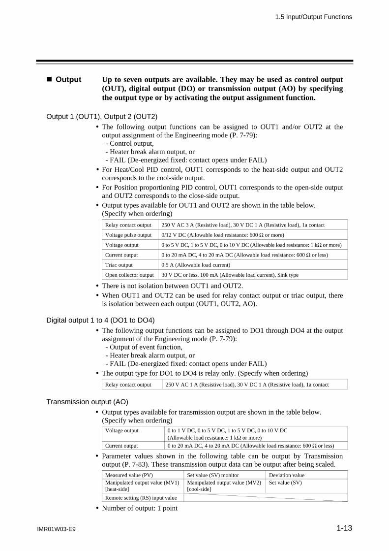
Output Up to seven outputs are available. They may be used as control output (OUT), digital output (DO) or transmission output (AO) by specifying the output type or by activating the output assignment function.
Output 1 (OUT1), Output 2 (OUT2)
The following output functions can be assigned to OUT1 and/or OUT2 at the output assignment of the Engineering mode (P. 7-79): - Control output, - Heater break alarm output, or - FAIL (De-energized fixed: contact opens under FAIL) For Heat/Cool PID control, OUT1 corresponds to the heat-side output and OUT2
corresponds to the cool-side output. For Position proportioning PID control, OUT1 corresponds to the open-side output
and OUT2 corresponds to the close-side output. Output types available for OUT1 and OUT2 are shown in the table below. (Specify when ordering)
Relay contact output 250 V AC 3 A (Resistive load), 30 V DC 1 A (Resistive load), 1a contact
Voltage pulse output 0/12 V DC (Allowable load resistance: 600 or more)
Voltage output 0 to 5 V DC, 1 to 5 V DC, 0 to 10 V DC (Allowable load resistance: 1 k or more)
Current output 0 to 20 mA DC, 4 to 20 mA DC (Allowable load resistance: 600 or less)
Triac output 0.5 A (Allowable load current)
Open collector output 30 V DC or less, 100 mA (Allowable load current), Sink type
There is not isolation between OUT1 and OUT2. When OUT1 and OUT2 can be used for relay contact output or triac output, there
is isolation between each output (OUT1, OUT2, AO). Digital output 1 to 4 (DO1 to DO4)
The following output functions can be assigned to DO1 through DO4 at the output assignment of the Engineering mode (P. 7-79): - Output of event function, - Heater break alarm output, or - FAIL (De-energized fixed: contact opens under FAIL) The output type for DO1 to DO4 is relay only. (Specify when ordering)
Relay contact output 250 V AC 1 A (Resistive load), 30 V DC 1 A (Resistive load), 1a contact
Transmission output (AO)
Output types available for transmission output are shown in the table below. (Specify when ordering)
Voltage output 0 to 1 V DC, 0 to 5 V DC, 1 to 5 V DC, 0 to 10 V DC (Allowable load resistance: 1 k or more)
Current output 0 to 20 mA DC, 4 to 20 mA DC (Allowable load resistance: 600 or less)
Parameter values shown in the following table can be output by Transmission output (P. 7-83). These transmission output data can be output after being scaled.
Measured value (PV) Set value (SV) monitor Deviation value Manipulated output value (MV1) [heat-side]
Manipulated output value (MV2) [cool-side]
Set value (SV)
Remote setting (RS) input value
Number of output: 1 point

1.5 Input/Output Functions
IMR01W03-E9 1-14
Communication Communication 1 (optional)
Communication 1 (COM1) is used for the Host communication. Communication protocol is used for RKC communication (ANSI X3.28-1976) or
Modbus. (Specify when ordering) Communication interface:
RS-422A *, RS-485, or RS-232C (Specify when ordering) * When Communication 1 is used for RS-422A, no Communication 2 can be used.
For details of the Host communication, refer to the separate FB100/FB400/ FB900 Communication Instruction Manual (IMR01W04-E).
Communication 2 (optional)
Communication 2 (COM2) is used for the Intercontroller communication. Data can be exchanged between two or more FB100s/400s/900s without using communication with analog signals such as remote setting input and analog output as well as with the host computer. (Refer to P. 6-60.) Interface: RS-485 only The following four functions become usable when the Intercontroller
communication is used. Automatic temperature rise function (with learning function) Cascade control function Ratio setting function Group RUN/STOP function
Loader communication
It is possible to manage data on the personal computer side by converting all of the data in the FB400/900 into one file. 1 When starting the Loader communication, first your PC (Windows
2000/XP/Vista/7) being used is necessary to be installed with the communication tool 2.
1 Use our communication converter COM-K (sold separately) to connect FB400/900 and your PC. 2 The communication tool (WinUCI, PROTEM2) can be downloaded from the RKC official website: http://www.rkcinst.com/.
The Loader port is only for parameter setup.
The Loader communication corresponds to the RKC communication protocol “Based on ANSI X3.28-1976 subcategories 2.5 and A4.”
For the COM-K, refer to the COM-K Instruction Manual (IMR01Z01-E).
1.5 Input/Output Functions
IMR01W03-E9 1-15
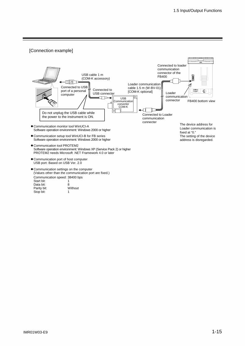
[Connection example]
USBCommunication
converter COM-K
USB cable 1 m (COM-K accessory)
Connected to loader communication connector of the FB400
Connected to USB port of a personal computer
Connected to USB connecter
The device address for Loader communication is fixed at “0.” The setting of the device address is disregarded.
Loader communication cable 1.5 m (W-BV-01) [COM-K optional]
Connected to Loader communication connecter
Loader communication connector FB400 bottom view
Do not unplug the USB cable while the power to the instrument is ON.
Communication monitor tool WinUCI-A Software operation environment: Windows 2000 or higher
Communication setup tool WinUCI-B for FB series Software operation environment: Windows 2000 or higher
Communication tool PROTEM2 Software operation environment: Windows XP (Service Pack 2) or higher PROTEM2 needs Microsoft .NET Framework 4.0 or later
Communication port of host computer USB port: Based on USB Ver. 2.0
Communication settings on the computer (Values other than the communication port are fixed.)
Communication speed: 38400 bps Start bit: 1 Data bit: 8 Parity bit: Without Stop bit: 1

1-16 IMR01W03-E9
MEMO

HANDLINGPROCEDURE TO
OPERATION
IMR01W03-E9 2-1

2. HANDLING PROCEDURE TO OPERATION
2-2 IMR01W03-E9
Handling Procedure to Operation
This chapter describes procedures to set operating conditions of a customer and parameter of various setting modes.
Setting procedure to operation
Conduct necessary setting before operation according to the procedure described below.
Mounting and Wiring
When installing the instrument, refer to 3. MOUNTING (P. 3-1) and 4. WIRING (P. 4-1).
Power ON
Change from RUN to STOP
Use the sheet of Appendix E,and make record of settingdata of a customer.
Factory set value: RUN (control start)
Setting of operating condition (Engineering mode)
Refer to 7.5. Engineering Mode (P. 7-48).
Entry to data sheet
The parameters in Engineering mode which should be set according to the application are settable only when the controller is in STOP mode.
Change from RUN mode to STOP mode with the RUN/STOP transfer. (P. 6-11)
The parameters for controller’s basic functions in Engineering mode should be changedaccording to the application before setting the parameters related to operation.
Be sure to check the parameters for the following settings and change them according to theapplication if necessary. Other parameters should be also changed according to the application. Power frequency [Factory set value 50Hz] (P. 7-76) Remote setting input type (P. 7-77) 2 Input type (P. 7-69) 1, 2 Event type (P. 7-85, 7-95, 7-102, 7-109) 2, 3 Input scale high/low (P. 7-72) 1, 2 Transmission output type (P. 7-83) 3 Control action (P. 7-129) 1, 2 Communication protocol (P. 7-168) 3 Output assignment (P. 7-79) 1, 2 1 This setting is not necessary when the quick start code “1” is specified. 2 This setting is not necessary when the quick start code “2” is specified. 3 This setting is not necessary when the quick start code “N” is specified.
A
When group operation by using Intercontrollercommunication is performed, refer to 6.14.1 Wiringmethod of the Intercontroller communication(P. 6-60).
When group operation by using Intercontroller communication is performed, set thefollowing setting items. Digital input (DI) assignment (P. 7-78) 1 Automatic temperature rise group (P. 7-165) 4 External input type (P. 7-125) 2, 3 RUN/STOP group (P. 7-166) 1, 4 Master channel selection (P. 7-126) 2, 3 1 Group RUN/STOP function (P. 6-63) 3 Ratio setting function (P. 6-91) 2 Cascade control function (P. 6-82) 4 Automatic temperature rise function (P. 6-72)

2. HANDLING PROCEDURE TO OPERATION
IMR01W03-E9 2-3
Setup data setting (Setup setting mode)
Parameter data setting
Refer to 7.3 Parameter Setting Mode (P. 7-19).
Up to 8 individual sets of parameters inParameter setting mode and SVs can bestored and used in Multi-memory areafunction.
To perform Ramp/Soak operation
Set parameters in Parameter setting mode: Event function relationships, PID and control response, etc. Set the Setting change rate
limiter, Area soak time and Link area number.
Control action type?
A
Position proportioning PID control
Adjustment of the valve position PID control or Heat/Cool PID control
For details, refer topage 6-40.
To perform group operation by using Intercontroller communication
Set the Device address 2, RS bias*, RS digital filter* and RS ratio*. * These parameter settings are also used
for Cascade control function (P. 6-82) and Ratio setting function (P. 6-91). Adjust the above parameter setting values when finely adjustment is required.
For details, refer topage 6-60.
Set the control set value (SV) which is target value of the control (refer to page 6-5).
Set value (SV) setting
The Set value (SV) can be stored up to 8 areas in Multi-memory area function as well asparameters in Parameter setting mode.
B
Set parameters in Setup setting mode:
Refer to 7.4 Setup Setting Mode (P. 7-34).
Heater break alarm relationships (optional), Input correction relationships, Communication (optional), etc.
For details, refer topage 6-50.

2. HANDLING PROCEDURE TO OPERATION
IMR01W03-E9 2-4
Control Memory Area selection
Select the Memory area in SV setting & monitor mode.
For details of memory area selection, refer to 6.9 Control Area Transfer (P. 6-32).
Yes
No Is Multi-memory Area *
function used? * Factory set value: Memory area 1
Operation *
B
Change from STOP to RUN [Change from STOP mode to RUN mode with the RUN/STOP transfer (P. 6-11). Operation starts as soon as the RUN/STOP mode is changed to RUN mode.]
Change from PID to AT (Operation mode: PID/AT transfer)
Change from “oFF (PID)” to “on (AT)” with the PID/AT transfer (P. 7-15). AT starts as soon as the PID/AT transfer is changed to “on.”
Tuning type?
Autotuning (AT) ST type setting
(Operation mode: STU)
Startup tuning (ST)
AT end
When the autotuning is finished, the controller will automatically returns to PID control.
* Adjust the PID constants manually when the optimum PID constants cannot be computed by Autotuning for characteristic variations of the controlled system (refer to page 6-9).
(P. 6-18)
ST end
When the startup tuning is finished,the controller will automatically returns to PID control.

MOUNTING
IMR01W03-E9 3-1
3.1 Mounting Cautions. ........................................................................... 3-2
3.2 Dimensions ....................................................................................... 3-3
3.3 Procedures of Mounting and Removing ............................................ 3-4

3. MOUNTING
3-2 IMR01W03-E9
3.1 Mounting Cautions
This chapter describes installation environment, mounting cautions, dimensions and mounting procedures.
(1) This instrument is intended to be used under the following environmental conditions. (IEC61010-1) [OVERVOLTAGE CATEGORY II, POLLUTION DEGREE 2]
(2) Use this instrument within the following environment conditions: Allowable ambient temperature: 10 to 50 C Allowable ambient humidity: 5 to 95 %RH
(Absolute humidity: MAX. W. C 29.3 g/m3 dry air at 101.3 kPa) Installation environment conditions: Indoor use
Altitude up to 2000 m
(3) Avoid the following conditions when selecting the mounting location: Rapid changes in ambient temperature which may cause condensation. Corrosive or inflammable gases. Direct vibration or shock to the mainframe. Water, oil, chemicals, vapor or steam splashes. Excessive dust, salt or iron particles. Excessive induction noise, static electricity, magnetic fields or noise. Direct air flow from an air conditioner. Exposure to direct sunlight. Excessive heat accumulation.
(4) Mount this instrument in the panel considering the following conditions: Provide adequate ventilation space so that heat does not build up. Do not mount this instrument directly above equipment that generates large amount of heat (heaters,
transformers, semi-conductor functional devices, large-wattage resistors.) If the ambient temperature rises above 50 C, cool this instrument with a forced air fan, cooler, etc.
Cooled air should not blow directly on this instrument. In order to improve safety and the immunity to withstand noise, mount this instrument as far away as
possible from high voltage equipment, power lines, and rotating machinery. High voltage equipment: Do not mount within the same panel. Power lines: Separate at least 200 mm. Rotating machinery: Separate as far as possible.
Mount this instrument in the horizontal direction for panel. If you did installation except a horizontal direction, this causes malfunction.
(5) If this instrument is permanently connected to equipment, it is important to include a switch or circuit-breaker into the installation. This should be in close proximity to the equipment and within easy reach of the operator. It should be marked as the disconnecting device for the equipment.
To prevent electric shock or instrument failure, always turn off the power before mounting or removing the instrument.
WARNING!

3. MOUNTING
IMR01W03-E9 3-3
3.2 Dimensions
FB400
FB900
*1 Case rubber packing FB400: KFB400-36 <1>, FB900: KFB900-36 <1> *2 Terminal cover KFB400-58(3) (optional) [sold separately] *3 When cutting out each mounting hole through a panel for individual mounting, observe that there is no bur or distortion along
the panel cutout surface, or there is no bend on the panel surface. If so, the water resistant characteristics may worsen. *4 Remove the case rubber packing. When the FB series is mounted closely protection will be compromised and they will not
meet IP66 (NEMA 4X) standards. *5 When controllers are closely mounted, ambient temperature must not exceed 50 C.
Close mounting *4, *5
L = 48×n-3 n: Number of controllers (2 to 6)
0.8
0
92
L0.6 0
Individual mounting *3
25 45 0.6 0
30
0.8
0
92
25 45 0.6 0
30
0.8
0
92
Individual mounting *3
25 92 0.8 0
30
0.8
0
92
L = 96×n-4 n: Number of controllers (2 to 6)
Close mounting *4, *5
L 0.8 0
0.8
0
92
Panel thickness: 1 to 10 mm (When mounting multiple FB400s close together, the panel strength should be checked to ensure proper support.)
Panel thickness: 1 to 10 mm (When mounting multiple FB900s close together, the panel strength should be checked to ensure proper support.)
(Unit: mm)
96
48
10.1
1 *1
91.8
106.
1
60
71.3
*2
44.8
49.2
(Unit: mm)
96
96
91.8
10.1
91.8
106.
1
60
71.3
*2
1 *1

3. MOUNTING
3-4 IMR01W03-E9
3.3 Procedures of Mounting and Removing
Mounting procedures
1. Prepare the panel cutout as specified in 3.2 Dimensions. (Panel thickness: 1 to 10 mm)
2. Insert the instrument through the panel cutout. 3. Insert the mounting bracket into the mounting
groove of the instrument. (Fig. 3.1) 4. Push the mounting bracket forward until the bracket
is firmly secured to the panel. (Fig. 3.2) 5. Only turn one full revolution after the screw touches
the panel. (Fig. 3.3) 6. The other mounting bracket should be installed
the same way described in 3. to 5.
The front of the instrument conforms to IP66 (NEMA4X) when mounted on the panel. For effective Waterproof/Dustproof, the gasket must be securely placed between instrument and panel without any gap. If gasket is damaged, please contact RKC sales office or the agent.
For replacing of rubber packing, refer to APPENDIX B. Replacing the Waterproof/ Dustproof Rubber Packing (P. A-4).
Removing procedures
1. Turn the power OFF. 2. Remove the wiring. 3. Loosen the screw of the mounting bracket. (Fig. 3.4) 4. Lift the latch of the mounting bracket (), then pull
the mounting bracket () to remove it from the case. (Fig. 3.4)
5. The other mounting bracket should be removed in the same way as described in 3. and 4.
6. Pull out the instrument from the mounting cutout while holding the front panel frame of this instrument. (Fig. 3.5)
Use long-nose pliers to remove mounting brackets from the instrument that is installed in a narrow place or installed tightly in a vertical position.
(FB900 is used in the right figures for explanation, but the same mounting procedures also apply to FB400.)
Fig. 3.2
Fig. 3.3
Fig. 3.1
Loosen the screw
Fig. 3.4
Front panel frame
Fig. 3.5
Pull out
Panel

WIRING
IMR01W03-E9 4-1
4.1 Wiring Cautions ................................................................................ 4-2
4.2 Terminal Layout ................................................................................ 4-5
4.3 Wiring of Each Terminal ................................................................... 4-7
4.4 Handling of the Terminal Cover [optional] ....................................... 4-15

4. WIRING
4-2 IMR01W03-E9
4.1 Wiring Cautions
This chapter describes wiring cautions, wiring layout and wiring of terminals.
For thermocouple input, use the appropriate compensation wire. For RTD input, use low resistance lead wire with no difference in resistance between the three lead
wires. To avoid noise induction, keep input signal wire away from instrument power line, load lines and
power lines of other electric equipment. If there is electrical noise in the vicinity of the instrument that could affect operation, use a noise
filter. Shorten the distance between the twisted power supply wire pitches to achieve the most effective
noise reduction. Always install the noise filter on a grounded panel. Minimize the wiring distance between the
noise filter output and the instrument power supply terminals to achieve the most effective noise reduction.
Do not connect fuses or switches to the noise filter output wiring as this will reduce the effectiveness of the noise filter.
About five seconds are required as preparation time for contact output every time the instrument is turned on. Use a delay relay when the output line is used for an external interlock circuit.
Power supply wiring must be twisted and have a low voltage drop. For an instrument with 24 V power supply, supply power from a SELV circuit. A suitable power supply should be considered in end-use equipment. The power supply must be in
compliance with a limited-energy circuits (maximum available current of 8 A). This instrument is not furnished with a power supply switch or fuse. Therefore, if a fuse or power
supply switch is required, install close to the instrument. Recommended fuse rating: Rated voltage 250 V, Rated current 1 A Fuse type: Time-lag fuse
Use the solderless terminal appropriate to the screw size. Screw size: M3 7 (With 5.8 5.8 square washer) Recommended tightening torque: 0.4 N・m (4 kgf・cm) Applicable wire: Solid/Twisted wire of 0.25 to 1.65 mm2 Specified dimension: Refer to Fig. 4.1 Specified solderless terminals: Manufactured by J.S.T MFG CO., LTD. Circular terminal with isolation V1.25-MS3 (M3 screw, width 5.5 mm, hole diameter 3.2 mm)
Make sure that the any wiring such as solderless terminal is not in contact with the adjoining terminals.
To prevent electric shock or instrument failure, do not turn on the power until all wiring is completed. Make sure that the wiring is correct before applying power to the instrument.
WARNING!
Fig. 4.1 5.5 MAX
3.2 MIN
5.6 mm 9.0 mm
5.0

4.1 Wiring Cautions
IMR01W03-E9 4-3
When making the connections, route from the left side toward the rear terminals as shown in Fig. 4.2. The central and right columns of terminals are slanted to facilitate connection from the left. If a terminal cover is used, connection from the right side is not possible. In a side-by-side installation, connecting from both the right and left sides may interfere with and prevent connections to the neighboring instrument.
Up to two solderless terminal lugs can be connected to one terminal screw. However, in this case, reinforced insulation cannot be used.
If solderless terminal lugs other than those in not specified dimensions are used, terminal screws may not be tightened. In such a case, bend each solderless terminal lug in advance and then conduct wiring. If the terminal screw is forcibly tightened, it may be damaged.
Fig. 4.3 Image of how to bend each solderless terminal lug
Panel
Top view (Example: Image of how to mount each FB900 side by side)
Connect from the left side
Fig. 4.2 Wiring direction
When a terminal cover is attached
Connection from the right side is not possible
Example: FB400
Example: FB400
Connect from the left side

4.1 Wiring Cautions
IMR01W03-E9 4-4
Caution for the terminal cover usage: If each solderless terminal lug touches the terminal cover, remove each projection from the terminal cover by manually bending it in front and in rear until broken. (Fig. 4.4)
For the mounting and removing of the terminal cover, refer to 4.4 Handling of the Terminal Cover [optional] (P. 4-15).
Fig. 4.4: Image of how to close the terminal board with the terminal cover and to remove these projections.
Top view
Terminal cover (optional) [sold separately] Terminal cover with the projection removed.
(Example: Image of how to close the terminal board with the terminal cover when each FB900 is mounted side by side.)
Terminal cover (KFB400-58(3))
This section illustrates the projections to be manually removed from the terminal cover when each terminal lug touches the cover.

4. WIRING
IMR01W03-E9 4-5
4.2 Terminal Layout
The terminal layout is as follows. FB400
FB900
Output 2 (OUT2) Relay contact/Voltage pulse/Voltage/Current/
Triac/Open collector
Transmission output (AO) [optional] Voltage/Current
Communication 1/ Communication 2 [optional] Communication 1 (RS-422A, RS-232C, RS-485) Communication 2 (RS-485)
Power supply voltage 100 to 240 V AC, 24 V AC, 24 V DC
Digital output 4 (DO4), Digital output 3 (DO3) [optional] Relay contact
Digital input (DI1 to DI4) [optional]For Memory area transfer
Remote setting (RS) input [universal input] Voltage/Current
Measured input [universal input]Thermocouple/RTD/Voltage/Current
Optional function Current transformer (CT) input
Power feed forward (PFF) input
Feedback resistance (FBR) input
Output 1 (OUT1) Relay contact/Voltage pulse/Voltage/Current/
Triac/Open collector
Digital input (DI5 to DI7) [standard]For Mode transfer
Digital output 2 (DO2), Digital output 1 (DO1) [optional] Relay contact
Communication 1/ Communication 2 [optional] Communication 1 (RS-422A, RS-232C, RS-485) Communication 2 (RS-485)
Power supply voltage 100 to 240 V AC, 24 V AC,
24 V DC
Digital input (DI1 to DI4)[optional] For Memory area transfer
Remote setting (RS) input[universal input] Voltage/Current
Measured input [universal input] Thermocouple/RTD/Voltage/
Current
Optional functionCurrent transformer (CT) input
Power feed forward (PFF) input
Feedback resistance (FBR) input
Digital input (DI5 to DI7)[standard] For Mode transfer
Output 2 (OUT2) Relay contact/Voltage pulse/ Voltage/Current/Triac/ Open collector
Transmission output (AO) [optional] Voltage/Current
Digital output 4 (DO4), Digital output 3 (DO3) [optional] Relay contact
Output 1 (OUT1) Relay contact/Voltage pulse/ Voltage/Current/Triac/ Open collector
Digital output 2 (DO2), Digital output 1 (DO1) [optional] Relay contact

4.2 Terminal Layout
IMR01W03-E9 4-6
Isolations of input and output (common to FB400/900)
: Isolated from each other circuit blocks. : Not isolated between inputs (or outputs).
Power supply Transmission output (AO)
Measured input Output 1 (OUT1) *
Remote setting input
Current transformer (CT) input Output 2 (OUT2) *
Power feed forward (PFF) input
Feedback resistance (FBR) input Digital output 1 (DO1)
Digital input (DI1) Digital output 2 (DO2)
Digital input (DI2)
Digital input (DI3) [Relay contact output (250 V AC 1A, 30 V DC 1 A)]
Digital input (DI4)
Digital input (DI5) Digital output 3 (DO3)
Digital input (DI6) Digital output 4 (DO4)
Digital input (DI7)
Communication 1/Communication 2 [Relay contact output (250 V AC 1A, 30 V DC 1 A)]
* When OUT1 and OUT2 can be used for relay contact output (250 V AC 3 A, 30 V DC 1 A) or triac output, there is isolation between each output (OUT1, OUT2, AO).
Output module
Output module

4. WIRING
IMR01W03-E9 4-7
4.3 Wiring of Each Terminal
Prior to conducting wiring, always check the polarity of each terminal.
Power supply
Connect the power to terminal numbers 1 and 2.
Power supply types must be specified when ordering. Power supply voltage for the controller must
be within the range shown below to accurse control accuracy. Specification
code Power supply type Power consumption
4 90 to 264 V AC (Power supply voltage range), [Rating 100 to 240 V AC] Power supply frequency: 50/60 Hz
FB400: 7.8 VA max. (at 100 V AC), 11.9 VA max. (at 240 V AC) FB900: 8.7 VA max. (at 100 V AC), 13.0 VA max. (at 240 V AC)
3
21.6 to 26.4 V AC (Power supply voltage range), [Rating 24 V AC] Power supply frequency: 50/60 Hz
FB400: 8.2 VA max. (at 24 V AC) FB900: 9.3 VA max. (at 24 V AC)
3
21.6 to 26.4 V DC (Power supply voltage range), [Rating 24 V DC]
FB400: 250 mA max. (at 24 V DC) FB900: 300 mA max. (at 24 V DC)
If there is electrical noise in the vicinity of the instrument that could affect operation, use a noise
filter. Power supply wiring must be twisted and have a low voltage drop. This instrument is not furnished with a power supply switch or fuse. Therefore, if a fuse or power
supply switch is required, install close to the instrument. Recommended fuse rating: Rated voltage 250 V, Rated current 1 A Fuse type: Time-lag fuse
For an instrument with 24 V power supply, supply power from a SELV circuit. A suitable power supply should be considered in end-use equipment. The power supply must be in
compliance with a limited-energy circuits (maximum available current of 8 A).
100-240 V AC power supply type
24 V AC power supply type 24 V DC power supply type
L
N
100-240 V AC
2
1L
N
24 V AC
2
1
24 V DC
2
1

4.3 Wiring of Each Terminal
IMR01W03-E9 4-8
Output 1 (OUT1)/Output 2 (OUT2)
Terminal 11 and 12 are for output 1 (OUT1); Terminal 9 and 10 are for output 2 (OUT2). Connect an appropriate load according to the output type. (Specify when ordering)
PID control (Direct/Reverse
action)
Heat/Cool PID control (or Position proportioning PID control) Wiring example
Relay contact output
Voltage pulse output
Voltage output/ Current output
Triac output
Open collector output
OUT1 is not isolated from OUT2. When OUT1 and OUT2 can be used for Relay contact output (250 V AC 3 A, 30 V DC 1 A) or
Triac output, there is isolation between each output (OUT1, OUT2, AO). OUT1 and OUT2 can be used for control output, Heater break alarm output, or FAIL (De-energized
fixed: Contact opens under FAIL). Refer to page 7-79. Continued on the next page.
12
11 OUT1
0/12 V DC SSR Load
~
12
11OUT1
10
9OUT2
Triac
12
11OUT1
Triac
10
9OUT2
Triac
12
11 OUT1
Load
~
12
11OUT1
10
9OUT2
Heat-side (Open-side)
NO
12
11 OUT1
Load
~
NO
OUT1
12
11
NO
OUT2
10
9
12
11OUT1
10
9OUT2Load
12
11 OUT1
NO
OUT1
12
11
Cool-side (Close-side)
Heat-side (Open-side) Cool-side (Close-side)
12
11 OUT1
Heat-side (Open-side) Cool-side (Close-side)
12
11 OUT1
12
11 OUT1
0 to 20 mA DC Actuator Load
~
Heat-side (Open-side) Cool-side (Close-side)
Triac
12
11 OUT1
Heat-side (Open-side) Cool-side (Close-side)
12
11 OUT1

4.3 Wiring of Each Terminal
IMR01W03-E9 4-9
Continued from the previous page.
Number of outputs and output types must be specified when ordering. The specifications of each output are as follows. Specification
code Output type Specifications
M Relay contact output
250 V AC, 3A (Resistive load)/30 V DC, 1 A (Resistive load) 1a contact
V Voltage pulse output
0/12 V DC (Allowable load resistance: 600 or more)
4
Voltage output
0 to 5 V DC (Allowable load resistance: 1 k or more)
5 0 to 10 V DC (Allowable load resistance: 1 k or more)
6 1 to 5 V DC (Allowable load resistance: 1 k or more)
7 Current output
0 to 20 mA DC (Allowable load resistance: 600 or less)
8 4 to 20 mA DC (Allowable load resistance: 600 or less)
T Triac output AC output (Allowable load current: 0.5 A [Ambient temperature 40 C or less]), Load voltage: 75 to 250 V AC, Minimum load current: 30 mA, ON voltage: 1.6 V or less (at maximum load current)
D Open collector output
Sink type (Allowable load current: 100 mA), Load voltage: 30 V DC or less, Minimum load current: 0.5 mA, ON voltage: 2 V or less (at maximum load current), Leakage current at OFF: 0.1 mA or less
Digital output 1 to 4 (DO1 to DO4) [optional]
With Digital output (optional), terminals 3 through 5 (DO3, DO4) and 6 through 8 (DO1, DO2) are allocated to the Digital output.
Output type is only Relay contact output.
Relay contact output 250 V AC, 1A (Resistive load)/30 V DC, 1 A (Resistive load) 1a contact Electrical life: 300,000 times or more (Rated load)
DO1 through DO4 can be used for output of the Event function, Heater break alarm output, or FAIL
(De-energized fixed: Contact opens under FAIL). Refer to page 7-79.
Wiring example
6COM
8DO1
NO
7DO2
NO
Load
~
Load
7
6
8
DO2
DO1
NO
COM
NO
4
3
5
DO4
DO3
NO
COM
NO

4.3 Wiring of Each Terminal
IMR01W03-E9 4-10
Transmission output (AO) [optional]
With Transmission output (optional), terminals 35 and 36 are allocated to the Transmission output.
Specification code Output type Specifications
3
Voltage output
0 to 1 V DC (Load resistance: 1 k or more)
4 0 to 5 V DC (Load resistance: 1 k or more)
5 0 to 10 V DC (Load resistance: 1 k or more)
6 1 to 5 V DC (Load resistance: 1 k or more)
7 Current output
0 to 20 mA DC (Load resistance: 600 or less)
8 4 to 20 mA DC (Load resistance: 600 or less)
Measured input (Thermocouple/RTD/Voltage/Current) [universal input]
For the Measured input type, terminals 22 through 24 are allocated to the Measured input.
The input types (input group) are as follows.
Input group Input type
Voltage (low) input
group
Thermocouple K, J, E, T, S, R, B, N, PLII, W5Re/W26Re, U, L
RTD Pt100, JPt100
Voltage (low) 0 to 1 V DC, 0 to 100 mV DC, 0 to 10 mV DC, 100 to 100 mV DC, 10 to 10 mV DC
Current 0 to 20 mA DC, 4 to 20 mA DC
Voltage (high) input group 1 to 1 V DC, 0 to 5 V DC, 1 to 5 V DC, 0 to 10 V DC
For Thermocouple input, use the appropriate compensation wire. For RTD input, use low resistance lead wires with no difference in resistance between the three lead
wires. To avoid noise induction, keep input signal wire away from instrument power line, load lines and
power lines of other electric equipment.
Wiring example
36
35 AO
4 to 20 mA DC Recorder
36
35 AO
RTD input
22
23
24
RTDA
B
B
Thermocouple input
TC
24
23
Voltage input
IN
24
23
Current input
IN
24
23

4.3 Wiring of Each Terminal
IMR01W03-E9 4-11
Remote setting (RS) input [universal input]
Remote setting (RS) input has provided as standard specifications. Terminal 20 and 21 are used for Remote setting (RS) input. Connect an input according to the Remote
setting (RS) input type*. * The following two methods of the RS input selection are available:
Specify when ordering (Initial setting code) Setting by Remote setting input type of Engineering mode (refer to page 7-77)
< Initial setting code (Quick start code 2)> Any one of the following input types can be selected.
Specification code Input type
Specification code Input type
1 Voltage input (0 to 10 mV DC) 5 Voltage input (0 to 10 V DC)
2 Voltage input (0 to 100 mV DC) 6 Voltage input (1 to 5 V DC)
3 Voltage input (0 to 1 V DC) 7 Voltage input (0 to 20 mA DC)
4 Voltage input (0 to 5 V DC) 8 Voltage input (4 to 20 mA DC)
Remote setting (RS) input is not isolated from the measured input. Digital input (DI1 to DI4 [optional], DI5 to DI7 [standard])
Terminals 30 through 34 for DI1 to DI4; and Terminals 13 through 16 for DI5 to DI7.
Digital input from external devices or equipment should be dry contact input. If it is not dry contact input, the input should have meet the specifications below. Contact specifications: At OFF (contact open): 500 k or more At ON (contact closed): 10 or less
The following functions can be assigned to Digital inputs.
DI1 to DI4: Memory area transfer (Number of area: 1 to 8) Area set DI5 to DI7: RUN/STOP, Remote/Local transfer, Auto/Manual transfer, Interlock release
To assign functions to Digital inputs, refer to 7.5 Engineering Mode “Digital input assignment” (P. 7-78).
Dry contact input
31
30
32
33
34
Memory area transfer(1 to 8)
Area set
DI2
DI1
DI3
COM ()
DI4
Dry contact input
14
13
15
16
DI6
DI5
DI7
COM ()
IN
21
20

4.3 Wiring of Each Terminal
IMR01W03-E9 4-12
Current transformer (CT) input/Power feed forward (PFF) input/ Feedback resistance (FBR) input [optional]
With Current transformer (CT) input, Power feed forward (PFF) input or Feedback resistance (FBR) input, terminals 17 through 19 are allocated to the specified input.
When using Current transformer (CT) input, connect CTs to the relevant terminals. When using Power feed forward (PFF) input, connect the dedicated transformer included. When using Feedback resistance (FBR) input, connect a potentiometer to the relevant terminals.
Current transformer (CT) input, Power feed forward (PFF) input, and Feedback resistance (FBR) input are not isolated between Measured input.
Communication 1/Communication 2 [optional]
With Communication function, terminals 25 through 29 are allocated to Communication. Conduct wiring to the relevant terminals meeting the specified communication interface. For details
of wiring, refer to FB400/FB900 Communication Quick Manual (IMR01N07-E).
Continued on the next page.
RS-232C [Communication 1]
RS-422A [Communication 1]
RS-485 [Communication 1]
CT input (1 point)
18
17
19
CT1
Specification code: T Initial setting code: P or S
CT input (2 point)
CT1 18
17
CT2
COM
19
Specification code: T Initial setting code: T or U
PFF input
18
17
PFF
19
Specification code: 1 or 2
CT input PFF input
CT1
18
17
PFF
COM
19
Specification code: 3 or 4 Initial setting code: P or S
FBR input
18
17
19
O
W
C Allowance resistance: Standard 135
Specification code: F
RS-232C [Communication 1] RS-485 [Communication 2]
SD
RD
SG
28
29
26
25
27
T (A) 26
25
T (B)
SG
27
28
29
R (A)
R (B)
T/R (A)
T/R (B)
SG
28
29
26
25
27
Specification code: 1 Initial setting code: 1 or 2
Specification code: 4 Initial setting code: 1 or 2
Specification code: 5 Initial setting code: 1 or 2
SD
RD
SG
28
29
T/R (A)
T/R (B)
26
25
27
RS-232C [Communication 1]
RS-485[Communication 2]
Specification code: W Initial setting code (Only Communication 1): 1 or 2
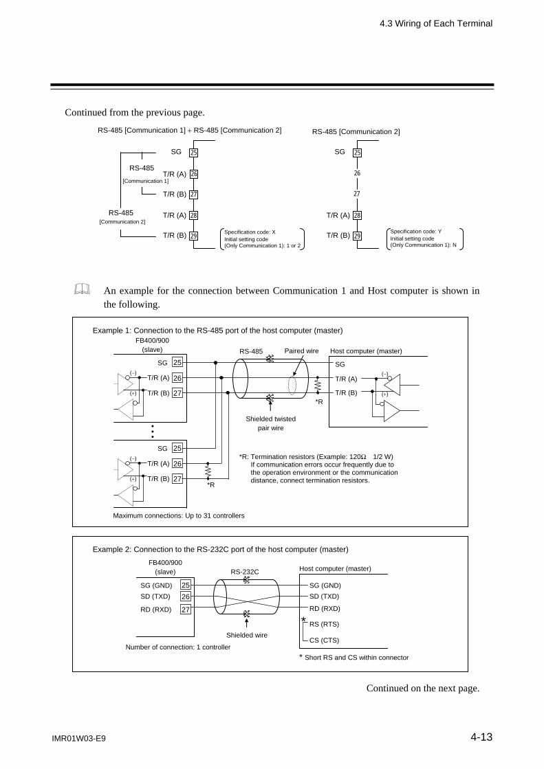
4.3 Wiring of Each Terminal
IMR01W03-E9 4-13
Continued from the previous page.
An example for the connection between Communication 1 and Host computer is shown in the following.
Continued on the next page.
Example 2: Connection to the RS-232C port of the host computer (master)
Host computer (master) RS-232C
Shielded wire
FB400/900 (slave)
Number of connection: 1 controller
SD (TXD)
RD (RXD)
SG (GND)
RS (RTS)
CS (CTS)
* Short RS and CS within connector
*
SD (TXD)
RD (RXD)
SG (GND)25
26
27
RS-485 [Communication 2]
SG
28
29
T/R (A)
T/R (B)
26
25
27
Specification code: Y Initial setting code (Only Communication 1): N
RS-485 [Communication 1] RS-485 [Communication 2]
SG
28
29
T/R (A)
T/R (B)
26
25
27
RS-485
[Communication 1]
RS-485 [Communication 2]
T/R (A)
T/R (B)
Specification code: X Initial setting code (Only Communication 1): 1 or 2
()
()
()
()
()
()
Example 1: Connection to the RS-485 port of the host computer (master)
RS-485
Paired wire
Shielded twistedpair wire
Maximum connections: Up to 31 controllers
*R
*R: Termination resistors (Example: 120 1/2 W) If communication errors occur frequently due to the operation environment or the communication distance, connect termination resistors.
*RT/R (B)
T/R (A)
SG
Host computer (master)
FB400/900 (slave)
T/R (A)
T/R (B)
SG 25
26
27
T/R (A)
T/R (B)
SG 25
26
27

4.3 Wiring of Each Terminal
IMR01W03-E9 4-14
Continued from the previous page. Communication 2 function (RS-485 only) is used for the Intercontroller communication.
For the Intercontroller communication, refer to 6.14 Group Operation by the Intercontroller Communication (P. 6-60).
Example 3: Connection to the RS-422A port of the host computer (master)
T (B)T (A)
R (B)R (A)
SG25 26 27 28 29
SG
T (B) T (A)
R (B) R (A)
25 26 27 28 29
SG
T (B) T (A)
R (B) R (A)
Maximum connections: Up to 31 controllers
FB400/900 (slave) RS-422A
Paired wire
Shielded twistedpair wire
Host computer (master)
()
() ()
()
()
() ()
()
()
()()
()
*R
*R
*R
*R
*R: Termination resistors (Example: 120 1/2 W) If communication errors occur frequently due to the operation environment or the communication distance, connect termination resistors.

4. WIRING
IMR01W03-E9 4-15
4.4 Handling of the Terminal Cover [optional]
When the mounting and removing of the terminal cover, take the following steps.
When mounting and removing the terminal cover, apply pressure very carefully for avoid damage to the terminal cover.
Mounting procedures
1. Check the mounting direction of the terminal cover. 2. Push the protrusions of terminal cover into the insertion slots for mounting the terminal cover.
Terminal cover
Parts code KFB400-58(3)
Ordering code 00491465
With the terminal cover to FB400
To prevent electric shock or instrument failure, always turn off the power before mounting or removing the terminal cover.
WARNING!
Insertion slots
Protrusions
With the terminal cover fixed to FB900
This section can be
removed by bending it.
Remove and then use it
depending on the wiring
condition.

4.4 Handling of the Terminal Cover [optional]
IMR01W03-E9 4-16
Removing procedures
Release the protrusions of terminal cover from the insertion slots () shown in the following figure, and then pull the terminal cover () to remove it from the case.

OPERTION MENU AND
BASIC OPERTION
IMR01W03-E9 5-1
5.1 Operation Menu ................................................................................ 5-2
5.2 Basic Operation ................................................................................ 5-4 5.2.1 Scrolling through parameters ............................................................... 5-4 5.2.2 Changing Set value (SV) ...................................................................... 5-8 5.2.3 Operation of the direct keys ................................................................. 5-9 5.2.4 Data lock function ............................................................................... 5-10

5. OPERATION MENU AND BASIC OPERATION
5-2 IMR01W03-E9
5.1 Operation Menu
The FB Series has five different setting modes. All settable parameters belong to one of them. The following chart shows how to access different setting mode.
For the details of key operation, refer to 5.2 Basic Operation (P. 5-4).
Power ON
Input type/Input range Display
SV setting & monitor mode - Set or change Set value (SV). - Monitor parameters such as PV, SV
and MV. - Conduct operation in this mode.
(Refer to P. 7-2)
Parameter setting mode - Change parameters related to
control such as PID values. - Stores up to 8 individual sets of
parameters and SVs by Multi-memory area function.
(Refer to P. 7-19)
Setup setting mode Set setting items not being in the memory area and lock levels.
(Refer to P. 7-34)
Operation mode - Change Operation status/mode such
as PID/AT, Auto/Manual, and Remote/Local.
- Set Startup tuning (ST).
(Refer to P. 7-14)
Engineering mode Change basic control functions such as Input/Output assignment.
(Refer to P. 7-48)
Press and hold the shift key for 2 seconds.
Press and hold the SET key for 2 seconds.
Press the shift key while pressing the SET key for 2 seconds.
Press the shift keywhile pressing the SET key.
Press the shift key while pressing the SET key.
The parameters in Engineering mode which should be set according to the application are settable only when the controller is in STOP mode.
Press and hold the SET key for 2 seconds.
Display returns to the SV setting and monitor mode from the Operation mode or the Parameter setting mode by pressing the shift key while pressing the SET key.
Display returns to the Measured value (PV)/Set value (SV) monitor screen if no key operation is performed within 1 minute (except during the Feedback adjustment or the Power feed forward input value monitor display).
Parameters not being specified are not displayed except in the Engineering mode.

5.1 Operation Menu
IMR01W03-E9 5-3
Input type and input range display
This instrument immediately confirms inputs type symbol and input range following power ON. Example: When sensor type is K thermocouple
Table 1: Input type symbol table
Symbol Input type
Thermocouple K Thermocouple J Thermocouple T Thermocouple S Thermocouple R Thermocouple E Thermocouple B Thermocouple N Thermocouple PLII Thermocouple W5Re/W26Re Thermocouple U Thermocouple L
RTD Pt100 RTD JPt100
Voltage (mV, V) Current (mA)
Unit for input and SV display: Celsius: C Fahrenheit: F Voltage/Current: no character shown
Power ON
Symbol
Input type symbol (Refer to table 1)
Automatically (in 2 seconds)
Automatically (in 2 seconds)
Input scale high
Input scale low
SV setting & monitor modeMeasured value (PV)/ Set value monitor

5. OPERATION MENU AND BASIC OPERATION
5-4 IMR01W03-E9
5.2 Basic Operation
Basic key operations common to each mode (set item change, set value change and registration) and Data lock function are described in the following. 5.2.1 Scrolling through parameters
SV setting & monitor mode
Operation method for SV setting & monitor mode differs depending on the Direct key type. The two key types of the Type 1 and Type 2 are available. The Direct key type can be selected in the Engineering mode. (1) When the Direct key type is Type 1: Pressing the MONI key enables the selection of only monitor screens in SV setting & monitor
mode. To go back to the first parameter, keep pressing MONI keys until it is displayed again. Pressing the SET key enables the selection of only setting screens in SV setting & monitor mode.
To go back to the first parameter, keep pressing SET keys until it is displayed again. Pressing the AREA key changes to the Memory area transfer screen. Pressing the SET key returns
to the Measured value (PV)/Set value (SV) monitor screen.
MONI key
MONIkey
MONI key
MONIkey
SET key
SET key
Measured value (PV)/ Set value (SV) monitor
Current transformer 1 (CT1) input value monitor
Current transformer 2 (CT2) input value monitor
Remote setting (RS) input value monitor
Event monitor 1
Memory area soak time monitor
Set value (SV)
Memory area transfer
Manipulated output valueat MV transfer
Interlock release
MONIkey
MONI key
SETkey
SETkey
AREA key
SET key
(P.7-7) (P.7-7) (P.7-7) (P.7-8)
(P.7-7) (P.7-11) (P.7-13)
(P.7-11)
(P.7-5)
(P.7-10)

5.2 Basic Operation
IMR01W03-E9 5-5
(2) When the Direct key type is Type 2: The monitoring, setting and Memory area transfer screen are mixedly displayed. Pressing the SET key enables screen selection. To go back to the first parameter, keep pressing SET keys until it is displayed again.
SET key
SETkey
SET key
SETkey
Measured value (PV)/ Set value (SV) monitor
Current transformer 1 (CT1) input value monitor
Current transformer 2 (CT2) input value monitor
Remote setting (RS) input value monitor
Event monitor 1
Set value (SV)
Interlock release
SETkey
SET key
SET key
(P.7-7) (P.7-7) (P.7-7) (P.7-7)(P.7-5)
(P.7-13) (P.7-8) Parameter setting mode, Setup setting mode
Press to scroll through parameters in the same mode/area. To go back to the first parameter, keep pressing SET keys until it is displayed again. If the type of Direct key is of Type 1, pressing the MONI key is changed to the Measured value
(PV)/Set value (SV) monitor screen. Parameter setting mode
Press and hold the SET key
for 2 seconds. SET key
SET key
SET key
Measured value (PV)/ Set value (SV) monitor
Event 1 set value (EV1)
Event 4 set value (EV4)
Proportional band [heat-side]
Link area number (LnKA)
SET key
SET key
Event 2 set value (EV2)
Event 3 set value (EV3)
SET key
(P.7-21) (P.7-21) (P.7-21) (P.7-21) (P.7-5)
(P.7-33) (P.7-24)
Setup setting mode
Press the shift keywhile pressing theSET key
SETkey
SET key
SETkey
Measured value (PV)/ Set value (SV) monitor
Heater break alarm 1 (HBA1) set value
Heater break alarm 2 (HBA2) set value
Heater break determination point 2
(HbL2)
Set lock level (LCK)
SETkey
SETkey
Heater break determination point 1
(HbL1)
Heater melting determination point 1
(HbH1)
SET key
(P.7-35) (P.7-38) (P.7-39) (P.7-35)(P.7-5)
(P.7-47) (P.7-38)

5.2 Basic Operation
IMR01W03-E9 5-6
Operation mode
Pressing the shift or SET key enables screen selection. To go back to the first parameter, keep pressing shift keys until it is displayed again. Pressing the UP or DOWN key enables operation mode selection. If the type of Direct key is of Type 1, pressing the MONI key is changed to the Measured value
(PV)/Set value (SV) monitor screen.
Press and hold
the Shift key for 2 seconds
Shift key
Shift key
Shift key
Measured value (PV)/ Set value (SV) monitor
Auto/Manual transfer (A-M)
Shift key
Startup tuning (ST)
Automatic temperature rise learning (CHr)
PID/AT transfer (ATU)
UP key
DOWN key
UP key
DOWNkey
UP key
DOWNkey
UP key
DOWNkey
UP key
DOWN key
Remote/Local transfer (r-L)
UP key
DOWN key
RUN/STOP transfer (r-S)
UP key
DOWNkey
Shift key
Shift key
(P.7-15)
(P.7-16)
(P.7-17) (P.7-17)
(P.7-5)
(P.7-18) (P.7-18)
Transferring the Operation mode immediately performs control in the mode transferred.

5.2 Basic Operation
IMR01W03-E9 5-7
Engineering mode
Pressing the UP or DOWN key enables function block selection. Pressing the SET key enables parameter selection. To go back to the first parameter, keep pressing UP or DOWN keys until it is displayed again. If the type of Direct key is of Type 1, pressing the MONI key is changed to the Measured value
(PV)/Set value (SV) monitor screen.
SET key Return to F10.
screen.
Measured value (PV)/ Set value (SV) monitor
SET key
Bar graph display resolution (dEUT)
PV flashing display at input error (dSoP)
STOP display (SPCH)
UP key
DOWN key
UP key
DOWN key
Press the shift key while pressing the SET key for 2 seconds
SET key
SET key
Bar graph display (dE)
SET key
SET key
SET key
SET key
Holding peak value ambient temperature
monitor (TCJ)
Power feed forward input value monitor (HEAT)
ROM version monitor
Integrated operating time monitor (WT)
Return to F11. screen.
Function block 10 (F10.)
Function block 11 (F11.)
Function block 91 (F91.)
SET key
SET key
SET key
SET key Return to F91.
screen.
Direct key 1 (Fn1)
Direct key 2 (Fn2)
Direct key 3 (Fn3)
Direct key type (Fn)
SET key
SET key
SET key
(P.7-62) (P.7-63) (P.7-65) (P.7-66) (P.7-62)
(P.7-67) (P.7-67) (P.7-68) (P.7-68) (P.7-67)
(P.7-171) (P.7-171) (P.7-172) (P.7-172) (P.7-171)
(P.7-5)

5.2 Basic Operation
IMR01W03-E9 5-8
5.2.2 Changing Set value (SV)
The high-lighted digit indicates which digit can be set. Press Shift key to go to a different digit. Every time the shift key is pressed, the high-lighted digit moves as follows.
High-lighted digit
The following is also available when changing the set value.
Increase SV from 199 °C to 200 °C: 1. Press the shift key to light brightly the ones place
(first digit from the right). 2. Press the UP key to change to 0.
The display changes to 200. Decrease SV from 200 °C to 190 °C: 1. Press the shift key to light brightly the tens place. 2. Press the DOWN key to change to 9.
The display changes to 190. Decrease SV from 200 C to –100 C: 1. Press the shift key to light brightly the hundreds place. 2. Press the DOWN key (three times) to change to 1.
The display changes to 100. To store a new value for the parameter, always press the SET key. The display changes to the
next parameter and the new value will be stored.
A new value will not be stored without pressing SET key after the new value is displayed on the display.
After a new value has been displayed by using the UP and DOWN keys, the SET key must be pressed within 1 minute, or the new value is not stored and the display will return to the Measured value (PV)/Set value (SV) monitor screen.

5.2 Basic Operation
IMR01W03-E9 5-9
5.2.3 Operation of the direct keys
Direct key type
The two Direct key types of the Type 1 and Type 2 are available. The Direct key type can be selected in the Engineering mode. (Refer to P. 7-68) The type of Direct key is set to Type 1 before factory shipment. If the type of direct key is changed to Type 2, stick an attached seal to the front surface of the instrument.
Direct key 1 Direct key 2 Direct key 3
Location where direct key seal (for type 2) is stuck
Also for the FB400, stick the direct key seal to the same location.
Direct key type Direct key 1 Direct key 2 Direct key 3
Type 1 A/M transfer key MONI key AREA key Type 2 A/M transfer key R/L transfer key R/S transfer key
A/M: Auto/Manual R/L: Remoter/Local R/S: RUN/STOP How to restrict operation of the direct keys
Three Direct function keys on the front panel are provided for one-key operation to switch Auto/Manual, Monitor screen (or Remote/Local), and Memory area (or RUN/STOP). Use/Unuse of Direct keys is settable in Engineering mode (function block 11). (Refer to P. 7-67)
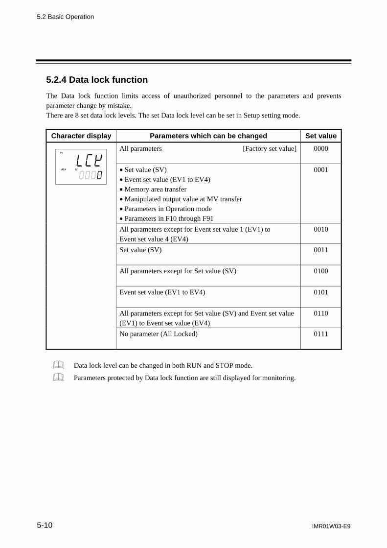
5.2 Basic Operation
IMR01W03-E9 5-10
5.2.4 Data lock function
The Data lock function limits access of unauthorized personnel to the parameters and prevents parameter change by mistake. There are 8 set data lock levels. The set Data lock level can be set in Setup setting mode.
Character display Parameters which can be changed Set value
All parameters [Factory set value]
0000
Set value (SV) Event set value (EV1 to EV4) Memory area transfer Manipulated output value at MV transfer Parameters in Operation mode Parameters in F10 through F91
0001
All parameters except for Event set value 1 (EV1) to Event set value 4 (EV4)
0010
Set value (SV)
0011
All parameters except for Set value (SV)
0100
Event set value (EV1 to EV4)
0101
All parameters except for Set value (SV) and Event set value (EV1) to Event set value (EV4)
0110
No parameter (All Locked)
0111
Data lock level can be changed in both RUN and STOP mode.
Parameters protected by Data lock function are still displayed for monitoring.
OPERATION
IMR01W03-E9 6-1
6.1 Operating Precautions .................................................................... 6-2
6.2 Monitoring Display in Operation ..................................................... 6-3
6.3 Operating Setting ........................................................................... 6-5 6.3.1 Set the Set value (SV) .......................................................................... 6-5 6.3.2 Set the Event set value (alarm set value) ............................................ 6-6 6.3.3 Autotuning (AT) start ............................................................................ 6-8
6.4 RUN/STOP Transfer .................................................................... 6-11
6.5 Autotuning (AT) ............................................................................ 6-15
6.6 Startup Tuning (ST) ...................................................................... 6-18
6.7 Auto/Manual Transfer ................................................................... 6-23
6.8 Remote/Local Transfer ................................................................. 6-28
6.9 Control Area Transfer ................................................................... 6-32
6.10 Interlock Release.......................................................................... 6-36
6.11 Start Action at Recovering Power Failure ..................................... 6-39
6.12 Position Proportioning PID Control ............................................... 6-40
6.13 Ramp/Soak Control ...................................................................... 6-50
6.14 Group Operation by the Intercontroller Communication ............... 6-60 6.14.1 Wiring method of the Intercontroller communication ........................ 6-60 6.14.2 Common setting of the Intercontroller communication ..................... 6-61 6.14.3 Group RUN/STOP function .............................................................. 6-63 6.14.4 Automatic temperature rise function (with learning function) ........... 6-72 6.14.5 Cascade control function .................................................................. 6-82 6.14.6 Ratio setting function ........................................................................ 6-91
6. OPERATION
6-2 IMR01W03-E9
6.1 Operating Precautions
Check the following items before starting operation, then turn on the power. Power ON
There is no power switch on this instrument, and the instrument starts operation immediately following initial power ON (Factory set value: RUN). Action at input error
If the input signal wiring is disconnected or short-circuited (RTD input only), the instrument determines that burnout has occurred.
Burnout direction Upscale: Thermocouple input 1, RTD input (at input break), Voltage (low) input Downscale: Thermocouple input 1, RTD input (at short-circuited), Voltage (low) input,
Voltage (high) input 2, Current input 2 1 For the Thermocouple input, upscale or downscale can be selected by Engineering mode.
(Factory set value: Upscale) 2 For the Voltage (high) input or the Current input, the display becomes indefinite (display of about zero
value).
Output at input error Control output: According to the contents set by Action (high/low) at input error Event output: According to the contents set by Event action at input error Checking the each parameter
The settings for the SV and all parameters should be appropriate for the controlled system. There are parameters in Engineering mode which can not be changed when the controller is in RUN mode. Change the RUN/STOP mode from RUN to STOP when a change for the parameters in Engineering mode is necessary.
For details of the each parameter, refer to 7. DESCRIPTION OF EACH PARAMETER (P. 7-1).
For details of RUN/STOP transfer, refer to 6.4 RUN/STOP Transfer (P. 6-11).
For details of the parameter in Engineering mode, refer to 7.5 Engineering Mode (P. 7-48). Operation when power failure
A power failure of 20 ms or less will not affect the control action. When a power failure of more than 20 ms occurs the instrument assumes that the power has been turned off. When the power returns, the operation of instrument will be re-starts in accordance with the content selected by Hot/Cold start.
For details of Hot/Cold start, refer to 6.11 Start Action at Recovering Power Failure (P. 6-39).
Event hold action
The event hold action is activated when the power is turned on or when transferred from STOP mode to RUN mode.
The event re-hold action is activated when not only the SV is changed, but also the power is turned on or when transferred from STOP mode to RUN mode.

6. OPERATION
IMR01W03-E9 6-3
6.2 Monitoring Display in Operation
In SV setting & monitor mode, the following operations are possible. When the power is turned on, the controller goes to this mode after self-diagnostics. Use this mode during normal operation. Selection method of monitor screens for SV setting & monitor mode differs depending on the Direct key type (Type 1, Type 2).
The factory set value of the Direct key type is Type 1 (A/M, MONI, AREA).
For the Direct key operation, refer to 5.2.3 Direct key operation (P. 5-9). Direct key type 1
Pressing the MONI key enables the selection of only monitor screens in SV setting & monitor mode. To go back to the first parameter, keep pressing MONI keys until it is displayed again.
MONI key
Display sequence of SV setting & monitor mode:
MONI key
MONI key
MONI key
MONI key
Measured value (PV)/ Set value (SV) monitor
Current transformer 1 (CT1) input value monitor
Current transformer 2 (CT2) input value monitor
Remote setting (RS) input value monitor
Event monitor 1
Memory area soak time monitor
MONI key
MONI key
MONI key
MONI key
MONI key
MONI key
Event monitor 2
Manipulated output value (MV1) monitor [heat-side]
Manipulated output value (MV2) monitor [cool-side]
(P.7-7) (P.7-7) (P.7-7) (P.7-8)(P.7-5)
(P.7-10) (P.7-10) (P.7-9) (P.7-8)
For the content of each screen, refer to 7.1 SV setting & Monitor Mode (P. 7-2).
Parameters which are not related to existing functions on the controller or not specified functions are not displayed as shown in the following. Current transformer 1 (CT1) input value monitor and Current transformer 2 (CT2) input
value monitor screens are not displayed if the CT inputs are not specified. Manipulated output value (MV1) monitor [heat-side] screen is not displayed if the
Feedback resistance (FBR) input is not used for Position proportioning PID control. The valve position from the control motor is displayed on Manipulated output value (MV1)
monitor [heat-side] screen if the Feedback resistance (FBR) input is used for Position proportioning PID control.
Manipulated output value (MV2) monitor [cool-side] screen is displayed if the Heat/Cool PID control is selected as control action.

6.2 Monitoring Display in Operation
IMR01W03-E9 6-4
Direct key type 2
Pressing the SET key enables the selection of screens. Monitor screens, Setting screens, and Memory area screen can be displayed. To go back to the first parameter, keep pressing SET keys until it is displayed again.
SET key
Display sequence of SV setting & monitor mode:
SET key
SET key
SET key
SET key
Measured value (PV)/ Set value (SV) monitor
Current transformer 1 (CT1) input value monitor
Current transformer 2 (CT2) input value monitor
Remote setting (RS) input value monitor
Set value (SV)
SET key
Event monitor 1 Event monitor 2 Manipulated output value (MV1) monitor [heat-side]
Manipulated output value (MV2) monitor [cool-side]
SET key
SET key
SET key
SET key
Interlock release
SET key
Memory area soak time monitor
Manipulated output valueat MV transfer
Memory area transfer
SET key
SET key
SET key
(P.7-7) (P.7-7) (P.7-7) (P.7-7)
(P.7-5)
(P.7-10) (P.7-9) (P.7-8) (P.7-8)
(P.7-13) (P.7-11) (P.7-11) (P.7-10)
For the content of each screen, refer to 7.1 SV setting & Monitor Mode (P. 7-2).
Parameters which are not related to existing functions on the controller or not specified functions are not displayed as shown in the following. Current transformer 1 (CT1) input value monitor and Current transformer 2 (CT2) input
value monitor screens are not displayed if the CT inputs are not specified. Manipulated output value (MV1) monitor [heat-side] screen is not displayed if the
Feedback resistance (FBR) input is not used for Position proportioning PID control. The valve position from the control motor is displayed on Manipulated output value (MV1)
monitor [heat-side] screen if the Feedback resistance (FBR) input is used for Position proportioning PID control. If the Feedback resistance (FBR) input is disconnected, the input value goes to over-scale (“oooo” display).
Manipulated output value (MV2) monitor [cool-side] screen is displayed if the Heat/Cool PID control is selected as control action.
Manipulated output value at MV transfer screen is not displayed if the MV transfer function is set to “0.”
Interlock release screen is not displayed if the Event interlock is set to “Unused.”

6. OPERATION
IMR01W03-E9 6-5
6.3 Operating Setting
An example of performing operation with SV set to 200 C and Event 1 set value [deviation high] set to 20 C is shown in the following. Operation procedures
Set the target value of control
Refer to 6.3.1 Set the Set value (SV) (P. 6-5)
Refer to 6.3.2 Set the Event set value (alarm set value) (P. 6-6)
Refer to 6.3.3 Autotuning (AT) start/stop (P. 6-8)
Set the Event set value
Autotuning (AT) start
6.3.1 Set the Set value (SV)
Example: Change the target value of the control to 200 C 1. Select the Set value (SV) screen
Press the SET key at PV/SV monitor screen until Set value (SV) screen is displayed.
PV/SV monitor Set value (SV)
2. Change the Set value (SV) The set value is set to 200 C by using the Shift and UP keys. The high-lighted digit indicates which digit can be set. Press the Shift key to high-light the hundreds digit. Press the UP key to change the number to 2.
Set value (SV)
High-lighted digit
Hundreds digit

6.3 Operating Setting
IMR01W03-E9 6-6
3. Store the set value (SV)
Press the SET key to store the new Set value (SV). The screen goes to the next parameter.
Set value (SV) Manipulated output value at MV transfer
After a new value is displayed on the display by using UP and DOWN keys, if no key operation is performed within 1 minute without pressing SET key, this instrument returns to the PV/SV monitor screen and the Set value (SV) will not be changed.
4. Return the PV/SV monitor
To return the PV/SV monitor, press the MONI key (for Direct key Type 1), or press the SET key several times.
PV/SV monitor
The changed Set value (SV)
6.3.2 Set the Event set value (alarm set value)
Example: Change the Event 1 set value (EV1) to 20 C
1. Select the Event 1 set value (EV1) screen Press and hold the SET key for 2 seconds at PV/SV monitor screen until Parameter setting mode is displayed. Event 1 set value (EV1) is displayed first.
PV/SV monitor
Event 1 set value (EV1) (Parameter setting mode)
Press and hold for 2 seconds Event set value screen is not displayed when the event function is not available.
The parameter that appears next after Set value (SV) varies depending on the specifications.

6.3 Operating Setting
IMR01W03-E9 6-7
2. Change the Event 1 set value (EV1)
The Event 1 set value (EV1) is set to 20 C by using the Shift and DOWN keys. The high-lighted digit indicates which digit can be set. Press the Shift key to high-light the tens digit. Press the DOWN key to change the number to 2.
Event 1 set value (EV1)
3. Store the new Event 1 set value (EV1) Press the SET key to store the new Event 1 set value (EV1). The screen goes to the next parameter.
Event 2 set value (EV2) [When the event 2 is used] Event 1 set value (EV1)
After a new value is displayed on the display by using UP and DOWN keys, if no key operation is performed within 1 minute without pressing SET key, this instrument returns to the PV/SV monitor screen and the Event 1 set value (EV1) will not be changed.
4. Return the PV/SV monitor
To return the PV/SV monitor, press the MONI key (for direct key type 1), or press and hold the SET key for 2 seconds.
For details of the event function, refer to 7.5 Engineering Mode (P. 7-85 to P. 7-115).

6.3 Operating Setting
IMR01W03-E9 6-8
6.3.3 Autotuning (AT) start
Autotuning (AT) automatically measures, computes and sets the optimum PID values.
Check that all of the requirements for AT start are satisfied before starting operation (refer to P. 6-15). To start Autotuning (AT), go to PID/AT transfer in Operation mode.
1. Select the PID/AT transfer screen
Press and hold the Shift key for 2 seconds at PV/SV monitor screen until Operation mode is displayed. PID/AT transfer screen is displayed first.
PV/SV monitor
PID/AT transfer (Operation mode)
Press and hold for 2 seconds
2. Start the Autotuning (AT) If set to “on” by pressing the UP key, the Autotuning function (AT) starts. At this time, the AT lamp flashes.
PID/AT transfer (Operation mode)
AT lamp
3. Autotuning (AT) finish When the Autotuning (AT) is finished, the control will automatically returns to PID control. At this time, the AT lamp turns off.
When canceling the Autotuning function (AT), press the DOWN key to be set to “oFF.”
To return the PV/SV monitor, press the MONI key (for Direct key Type 1), or press and hold the Shift key for 2 seconds.
If Autotuning (AT) ends normally, the LBA time is automatically set twice as large as the Integral time.

6.3 Operating Setting
IMR01W03-E9 6-9
To manually set PID values
If the autotuning function does not match the controlled object requirements, the optimum PID values may not be computed by Autotuning (AT). In that case, adjust the PID values manually. Setting procedure 1. Select the Parameter setting mode
Press and hold the SET key for 2 seconds at PV/SV monitor screen until Parameter setting mode is displayed. Event 1 set value (EV1) is displayed first.
PV/SV monitor
Event 1 set value (EV1)(Parameter setting mode )
Press and hold for 2 seconds Event set value screen is not displayed when the event function is not available.
2. Select the Proportional band [heat-side] screen
Press the SET key several times to change to the Proportional band [heat-side] screen.
Event 1 set value (EV1) Proportional band [heat-side]
3. Change the Proportional band [heat-side] set value The Proportional band [heat-side] set value is set to 10 C by using the Shift and DOWN keys (Example: 10 C). The high-lighted digit indicates which digit can be set. Press the Shift key to high-light the tens digit. Press the DOWN key to change the number to 1.
Proportional band [heat-side]

6.3 Operating Setting
IMR01W03-E9 6-10
4. Store the Integral time [heat-side] set value
Press the SET key to store the new Proportional band [heat-side] set value. The screen goes to the next Integral time [heat-side].
Integral time [heat-side] Proportional band [heat-side]
After a new value is displayed on the display by using UP and DOWN keys, if no key operation is performed within 1 minute without pressing SET key, this instrument returns to the PV/SV monitor screen and the Proportional band [heat-side] set value will not be changed.
5. Set the Integral time [heat-side] and Derivative time [heat-side]
The setting procedure applies when the Integral time [heat-side] and the Derivative time [heat-side] are also set.
Derivative time [heat-side]Integral time [heat-side]
6. Return the PV/SV monitor To return the PV/SV monitor, press the MONI key (for direct key type 1), or press and hold the SET key for 2 seconds.
For the setting range of PID values, refer to 7.3 Parameter Setting Mode (P. 7-24 to P. 7-25).

6. OPERATION
IMR01W03-E9 6-11
6.4 RUN/STOP Transfer
The RUN/STOP transfer can be made by Digital input (DI) or Communication (optional) other than the key operation.
When the digital input RUN/STOP transfer function is used, it is impossible to transfer RUN/STOP through key operation if the contact (DI5) is not closed. (When DI5 opens: STOP mode is maintained.)
For details of the RUN/STOP transfer by Communication, refer to the separate FB100/FB400/FB900 Communication Instruction Manual (IMR01N04-E).
State of this instrument when set to STOP mode
STOP display Displays the STOP symbol “SToP” on the SV or PV displays. (Factory set value: SV displays)
Control output
PID control Output depending on the Manipulated output value (MV1) at STOP mode (Factory set value: 5.0 %)
Heat/Cool PID control
Heat-side: Output depending on the Manipulated output value (MV1) at STOP mode (Factory set value: 5.0 %)
Cool-side: Output depending on the Manipulated output value (MV2) at STOP mode (Factory set value: 5.0 %)
Position proportioning PID control
When there is no Feedback resistance (FBR) input: Conform to the set value of the Valve action at STOP mode.
When there is Feedback resistance (FBR) input: Manipulated output value (MV) at STOP mode corresponds to Feedback resistance (FBR) input value.
When there is Feedback resistance (FBR) input, and it is input break: Conform to the set value of the Valve action at STOP mode.
Event output Output depending on the output status at STOP mode (Factory set value: OFF) HBA output
Transmission output
For the settings of STOP display, Output status at STOP mode, and Manipulated output value (MV) at STOP mode, refer to 7.5 Engineering Mode (P. 7-62, P. 7-82 and P. 7-136).
State of this instrument when set to RUN mode
Operation when transferred to RUN from STOP is in accordance with the Hot/Cold start selection setting.
For the Hot/Cold start selection, refer to 6.11 Start Action at Recovering Power Failure (P. 6-39).
RUN/STOP transfer by Front key operation
1. Press and hold the SET key for 2 seconds at PV/SV monitor screen until Operation mode is displayed.
PV/SV monitor
PID/AT transfer (Operation mode)
Press and hold for 2 seconds

6.4 RUN/STOP Transfer
IMR01W03-E9 6-12
2. Press the Shift key several times until RUN/STOP transfer screen is displayed.
RUN/STOP transfer PID/AT transfer (Operation mode)
RUN mode
3. Pressing the UP key changes to STOP mode from RUN mode.
RUN/STOP transfer
STOP mode
Symbol of showing STOP
PV/SV monitor (STOP mode)
Press and hold the Shift key for 2 seconds
To change from STOP mode to RUN mode, press the DOWN key.
RUN/STOP transfer
RUN mode
RUN/STOP transfer by Direct key (R/S) operation
RUN/STOP transfer by the Direct key is possible with the Direct key type of the Engineering mode. Set “2: Type 2” to the Direct key type. Every time the RUN/STOP (R/S) transfer key is pressed, the RUN mode is changed to the STOP mode alternately.
For the Direct key type selection, refer to 7.5 Engineering Mode (P. 7-68). To change from RUN mode to STOP mode
PV/SV monitor (RUN mode)
RUN/STOP transfer (Operation mode)
Symbol of showing STOP
PV/SV monitor (STOP mode)
Display changes automatically
Press the <R/S key

6.4 RUN/STOP Transfer
IMR01W03-E9 6-13
To change from STOP mode to RUN mode
PV/SV monitor (STOP mode)
RUN/STOP transfer (Operation mode)
RUN mode
PV/SV monitor (RUN mode)
Display changes automatically
Press the <R/S key
RUN/STOP transfer by Digital input (DI)
RUN/STOP transfer by the Digital input (DI) is possible with the Digital input (DI) of the Engineering mode.
For the Digital input (DI) assignment, refer to 7.5 Engineering Mode (P. 7-78). Terminal Configuration
Digital input (DI 5 to DI 7)
Contact input from external devices or equipment should be dry contact input. If it is not dry contact input, the input should have meet the specifications below. Contact specifications: At OFF (contact open) 500 k or more At ON (contact closed) 10 or less
DI 5: RUN/STOP transfer input Contact closed: RUN Contact open: STOP
DI 5 14
13
15 DI 6
COM
16 DI 7
Transfer timing of RUN/STOP When the contact is closed, RUN. When the contact is open, STOP.
After the contact is transferred, it takes “200 ms 1 sampling cycle* ” until the action of this instrument is actually selected. * Sampling cycle: The value selected by the sampling cycle of the Engineering mode. (Factory set value: 100 ms)
200 ms or more
Contact open
Contact closed
STOP
RUN
200 ms or more
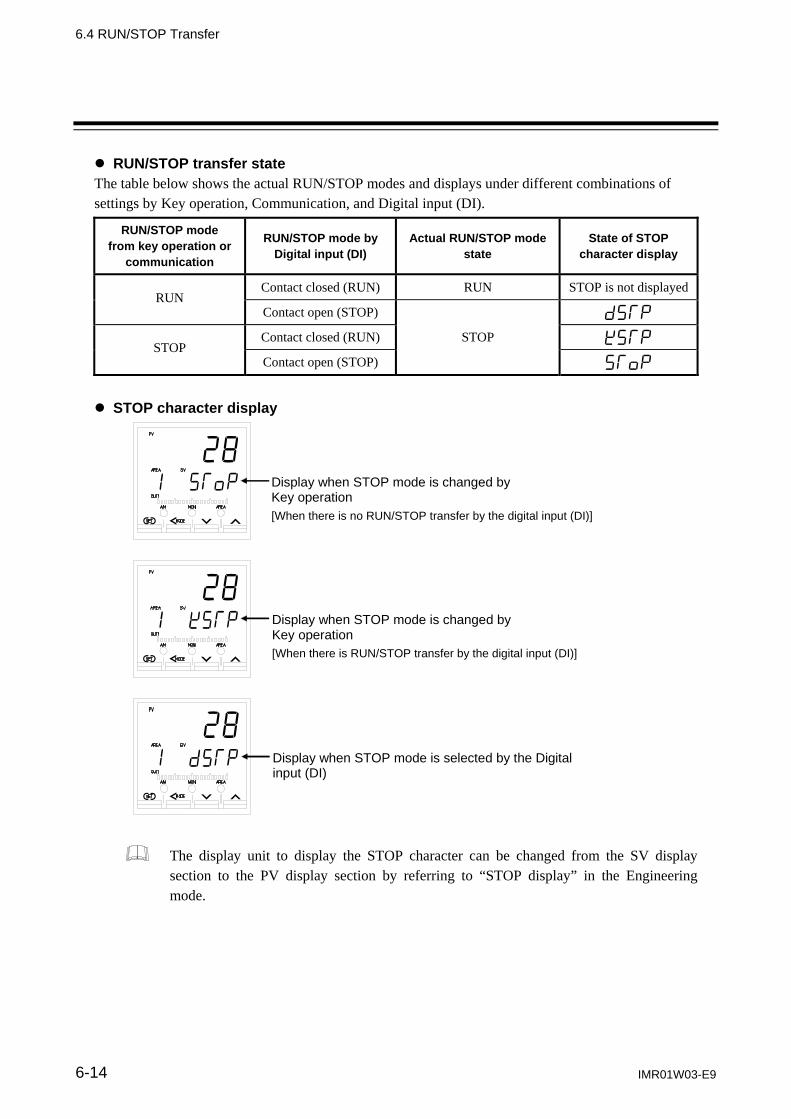
6.4 RUN/STOP Transfer
IMR01W03-E9 6-14
RUN/STOP transfer state The table below shows the actual RUN/STOP modes and displays under different combinations of settings by Key operation, Communication, and Digital input (DI).
RUN/STOP mode from key operation or
communication
RUN/STOP mode by Digital input (DI)
Actual RUN/STOP mode state
State of STOP character display
RUN Contact closed (RUN) RUN STOP is not displayed
Contact open (STOP) dSTP
STOP Contact closed (RUN) STOP KSTP
Contact open (STOP) SToP
STOP character display
Display when STOP mode is changed by Key operation [When there is no RUN/STOP transfer by the digital input (DI)]
Display when STOP mode is changed by Key operation [When there is RUN/STOP transfer by the digital input (DI)]
Display when STOP mode is selected by the Digital input (DI)
The display unit to display the STOP character can be changed from the SV display section to the PV display section by referring to “STOP display” in the Engineering mode.

6. OPERATION
IMR01W03-E9 6-15
6.5 Autotuning (AT)
The Autotuning (AT) function automatically measures, computes and sets the optimum PID values. The Autotuning (AT) can be used for PID control (Direct/Reverse action), Heat/Cool PID control, and Position proportioning PID control (Direct/Reverse action). Caution for using the Autotuning (AT)
When a temperature change (UP and/or Down) is 1 C or less per minute during Autotuning (AT), Autotuning (AT) may not be finished normally. In that case, adjust the PID values manually. Manual setting of PID values may also be necessary if the set value is around the ambient temperature or is close to the maximum temperature achieved by the load.
If the output change rate limiter is set, the optimum PID values may not be computed by Autotuning (AT).
Requirements for Autotuning (AT) start
Start the Autotuning (AT) when all following conditions are satisfied: To start Autotuning (AT), go to PID/AT transfer in Operation mode.
Operation mode state
RUN/STOP transfer RUN PID/AT transfer PID control Auto/Manual transfer Auto mode Remote/Local transfer Local mode
Parameter setting Output limiter high 0.1 %, Output limiter low 99.9 % Input value state The Measured value (PV) is not underscale or over-scale.
Input error determination point (high) Measured value (PV) Input error determination point (low)
Requirements for Autotuning (AT) cancellation
If the Autotuning (AT) is canceled according to any of the following conditions, the controller immediately changes to PID control. The PID values will be the same as before Autotuning (AT) was activated.
When the Operation mode is transferred
When the RUN/STOP mode is changed to the STOP mode. When the PID/AT transfer is changed to the PID control. When the Auto/Manual mode is changed to the Manual mode. When the Remote/Local mode is changed to the Remote mode.
When the parameter is changed
When the temperature Set value (SV) is changed. When the PV bias, the PV digital filter, or the PV ratio is changed. When the control area is changed.
When the input value becomes abnormal
When the Measured value (PV) goes to underscale or over-scale. When the Measured value (PV) goes to input error range. (Measured value (PV) Input error determination point (high) or Input error determination point (low) Measured value (PV))
When the AT exceeded the execution time
When the AT does not end in two hours after AT started.
Power failure When the power failure of more than 20 ms occurs. Instrument error When the instrument is in the FAIL state.

6.5 Autotuning (AT)
IMR01W03-E9 6-16
Autotuning (AT) start/stop operation
The Autotuning function can start from any state after power on, during a rise in temperature or in stable control.
1. Press and hold the Shift key for 2 seconds at PV/SV monitor screen until Operation mode is displayed. PID/AT transfer screen is displayed first.
PV/SV monitor
PID/AT transfer(Operation mode)
Press and hold for 2 seconds
2. If set to “on” by pressing the UP key, the Autotuning (AT) function starts. At this time, the AT
lamp flashes.
PID/AT transfer (Operation mode) AT lamp flashes
3. When the Autotuning (AT) is finished, the control will automatically returns to PID control. At this time, the AT lamp turns off.
When canceling the Autotuning (AT) function, press the DOWN key to be set to “oFF.”
PID/AT transfer (Operation mode) AT lamp turns off

6.5 Autotuning (AT)
IMR01W03-E9 6-17
Parameters for Autotuning (AT)
Parameters for Autotuning (AT) are provided to compute the PID values suitable for various controlled systems and control actions. Set them, as required. Set the parameters for Autotuning (AT) in the Engineering mode. Example 1: When you want to find each constant suited for P control, PI control, or PD control by
Autotuning. For P control:
Set “0” to Integral time limiter (high) [heat-side] and Derivative time limiter (high) [heat-side].
For PI control: Set “0” to Derivative time limiter (high) [heat-side].
For PD control: Set “0” to Integral time limiter (high) [heat-side].
When Autotuning (AT) is executed by making the settings above, the control constants suited for P, PI, or PD control are found.
Also corresponds to Heat/Cool PID control cool-side and Position proportioning PID control.
Example 2: When you want to limit on/off output only at Autotuning (AT)
Autotuning (AT) that limits the ON/OFF output values only at Autotuning (AT) can be executed by setting the output value with AT turned on and the output value with AT turned off.
Only when the Feedback resistance (FBR) input is connected in the Position proportioning PID control, the “Output value with AT turned on” and “Output value with AT turned off” setting becomes valid.
As the other parameters for Autotuning (AT) function, there are AT bias, AT cycle, or AT differential gap time. For the each parameter, refer to 7.5 Engineering Mode (P. 7-146 to P. 7-148).
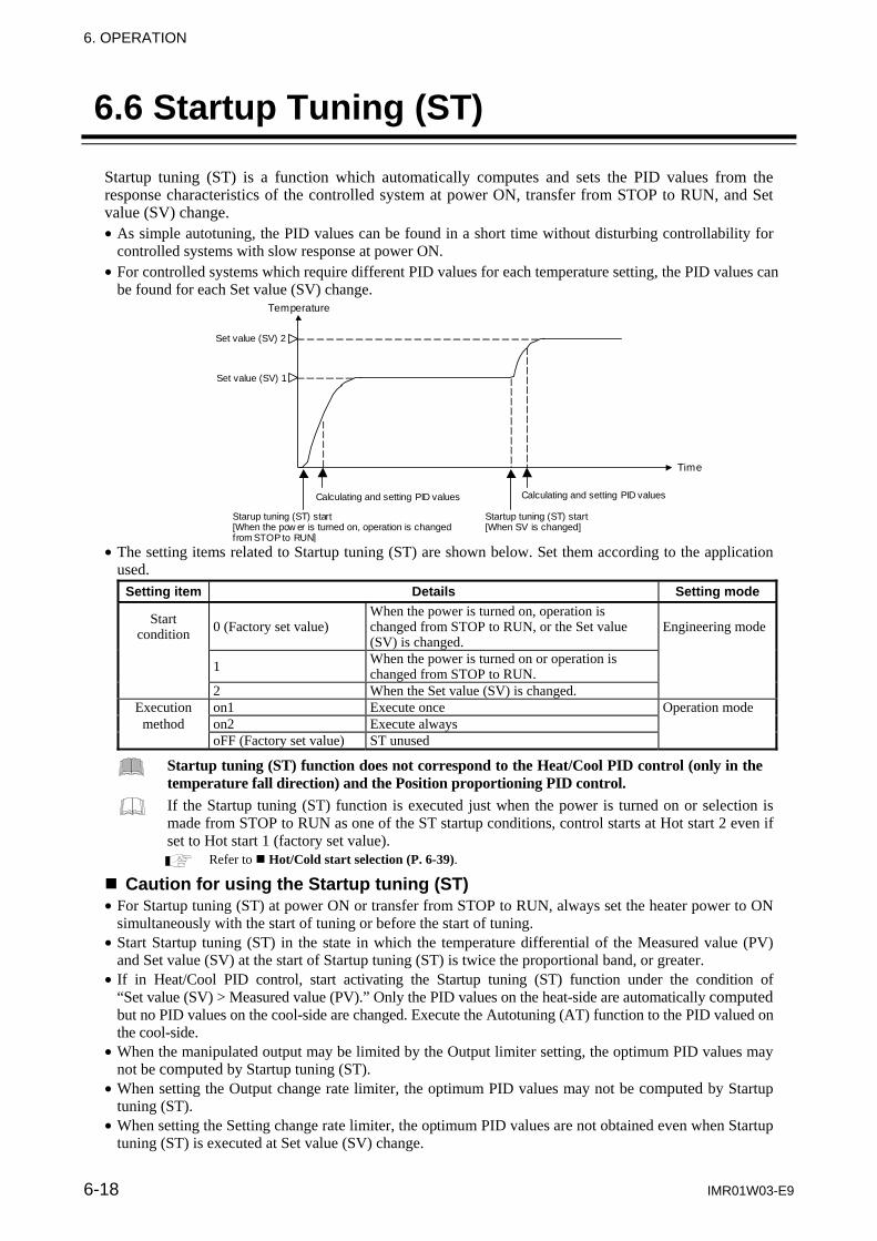
6. OPERATION
6-18 IMR01W03-E9
6.6 Startup Tuning (ST)
Startup tuning (ST) is a function which automatically computes and sets the PID values from the response characteristics of the controlled system at power ON, transfer from STOP to RUN, and Set value (SV) change. As simple autotuning, the PID values can be found in a short time without disturbing controllability for
controlled systems with slow response at power ON. For controlled systems which require different PID values for each temperature setting, the PID values can
be found for each Set value (SV) change.
Time
Temperature
Set value (SV) 2
Starup tuning (ST) start [When the pow er is turned on, operation is changed from STOP to RUN]
Calculating and setting PID values
Calculating and setting PID values
Startup tuning (ST) start [When SV is changed]
Set value (SV) 1
The setting items related to Startup tuning (ST) are shown below. Set them according to the application
used. Setting item Details Setting mode
Start condition 0 (Factory set value)
When the power is turned on, operation is changed from STOP to RUN, or the Set value (SV) is changed.
Engineering mode
1 When the power is turned on or operation is changed from STOP to RUN.
2 When the Set value (SV) is changed. Execution on1 Execute once Operation mode
method on2 Execute always oFF (Factory set value) ST unused
Startup tuning (ST) function does not correspond to the Heat/Cool PID control (only in the temperature fall direction) and the Position proportioning PID control.
If the Startup tuning (ST) function is executed just when the power is turned on or selection is made from STOP to RUN as one of the ST startup conditions, control starts at Hot start 2 even if set to Hot start 1 (factory set value).
Refer to Hot/Cold start selection (P. 6-39). Caution for using the Startup tuning (ST) For Startup tuning (ST) at power ON or transfer from STOP to RUN, always set the heater power to ON
simultaneously with the start of tuning or before the start of tuning. Start Startup tuning (ST) in the state in which the temperature differential of the Measured value (PV)
and Set value (SV) at the start of Startup tuning (ST) is twice the proportional band, or greater. If in Heat/Cool PID control, start activating the Startup tuning (ST) function under the condition of
“Set value (SV) > Measured value (PV).” Only the PID values on the heat-side are automatically computed but no PID values on the cool-side are changed. Execute the Autotuning (AT) function to the PID valued on the cool-side.
When the manipulated output may be limited by the Output limiter setting, the optimum PID values may not be computed by Startup tuning (ST).
When setting the Output change rate limiter, the optimum PID values may not be computed by Startup tuning (ST).
When setting the Setting change rate limiter, the optimum PID values are not obtained even when Startup tuning (ST) is executed at Set value (SV) change.

6.6 Startup Tuning (ST)
IMR01W03-E9 6-19
Requirements for Startup tuning (ST) start
Start the Startup tuning (ST) when all following conditions are satisfied:
Operation mode state
RUN/STOP transfer RUN
PID/AT transfer PID control
Auto/Manual transfer Auto mode
Remote/Local transfer Local mode
Parameter setting Startup tuning (ST) is set to ON. (Execute once, Execute always)
Output limiter high 0.1 %, Output limiter low 99.9 %
Input value state
The Measured value (PV) is not underscale or over-scale. Input error determination point (high) Measured value (PV) Input error determination point (low) At Startup tuning (ST) at Set value (SV) change, the Measured value (PV) shall be stabilized. Set value (SV) > Measured value (PV) (Heat/Cool PID control)
Output value state At startup, output is changed and saturated at the Output limiter high or the Output limiter low.
Requirements for Startup tuning (ST) cancellation
If the Startup tuning (ST) is canceled according to any of the following conditions, the controller immediately changes to PID control. The PID values will be the same as before ST was activated.
When the parameter is changed When Startup tuning (ST) is set to OFF
When the PV bias, the PV digital filter, or the PV ratio is changed.
When the Operation mode is transferred
When the RUN/STOP mode is changed to the STOP mode.
When the Autotuning (AT) is activated.
When the Auto/Manual mode is changed to the Manual mode.
When the Remote/Local mode is changed to the Remote mode.
When the input value becomes abnormal
When the Measured value (PV) goes to underscale or over-scale.
When the Measured value (PV) goes to input error range. (Measured value (PV) Input error determination point (high) or Input error determination point (low) Measured value (PV))
When the ST exceeded the execution time
When the ST does not end in hundred minutes after ST started.
Power failure When the power failure of more than 20 ms occurs.
Instrument error When the instrument is in the FAIL state.

6.6 Startup Tuning (ST)
IMR01W03-E9 6-20
Startup tuning (ST) setting
The setting procedure when executing Startup tuning (ST) only one time at power ON is shown below as a setting example.
Step 1: Set the start condition First, set “When the power is turn on” to Startup tuning (ST) start condition by Engineering mode.
1. Change the operation mode from RUN mode to STOP mode.
To change from RUN mode to STOP mode, refer to 6.4 RUN/STOP Transfer (P. 6-11).
2. Press the Shift key while pressing the SET key for 2 seconds at PV/SV monitor screen until Engineering mode is displayed. Function block 10 screen is displayed first.
PV/SV monitor
Function block 10(Engineering mode)
Press the Shift key while pressing the SET key for 2 seconds
3. Press the DOWN key six times until Function block 54 screen is displayed.
Function block 10 (Engineering mode)
Function block 54 (Engineering mode)
4. Press the SET key until ST start condition screen will be displayed.
Function block 54 (Engineering mode)
ST start condition (Engineering mode)

6.6 Startup Tuning (ST)
IMR01W03-E9 6-21
5. Press the UP key to change the number to 1.
ST start condition (Engineering mode)
1: Activate the ST function when the power is turned on; or when transferred from STOP to RUN
Setting range: 0: Activate the ST function when the power is turned on; when transferred from STOP to RUN; or when the Set value (SV) is changed 1: Activate the ST function when the power is turned on; or when transferred from STOP to RUN 2: Activate the ST function when Set value (SV) is changed
6. Press the SET key to store the new value. The screen goes to the ST proportional band adjusting
factor screen.
ST start condition (Engineering mode)
ST proportional band adjusting factor
(Engineering mode)
7. To return the PV/SV monitor, press the MONI key (for direct key type 1), or press the Shift key
while pressing the SET key. Step 2: Set the execution method
Set that the Startup tuning (ST) will be executed only once.
1. Change the operation mode from STOP mode to RUN mode by RUN/STOP transfer screen of Operation mode.
To change from STOP mode to RUN mode, refer to 6.4 RUN/STOP Transfer (P. 6-11).
2. Press the Shift key twice at RUN/STOP transfer screen until Startup tuning (ST) screen is displayed.
RUN/STOP transfer (Operation mode)
Startup tuning (ST)(Operation mode)

6.6 Startup Tuning (ST)
IMR01W03-E9 6-22
3. Press the UP key to set “on1 (Execute once).”
Startup tuning (ST) (Operation mode)
on1: Execute once
Setting range: on1: Execute once on2: Execute always oFF: ST unused
4. Thus, the Startup tuning (ST) setting has been finished. Step 3: Start the Startup tuning (ST)
Turn off the power once and turn it on again. The Startup tuning (ST) will automatically start. When the calculation and setting of PID values is completed, setting of the Startup tuning (ST) screen will automatically change to “oFF.”
Startup tuning (ST) (Operation mode)
If the setting is set to “Execute once”: When the Startup tuning (ST) is finished, the setting will automatically return to “oFF.”
When Startup tuning (ST) was interrupted, the setting does not change to “oFF.” Startup tuning (ST) starts when the restart conditions are satisfied.
As the parameters for Startup tuning (ST) function, there are ST proportional band adjusting factor, ST integral time adjusting factor, and ST derivative time adjusting factor in Engineering mode. However, use the same setting as the factory set values (1.00 times). Example: When set the proportional band adjusting factor Proportional band (P)
Computed proportional band Proportional band adjusting factor (0.01 to 10.00 times)

6. OPERATION
IMR01W03-E9 6-23
6.7 Auto/Manual Transfer
The Auto/Manual transfer can be made by Digital input (DI) or Communication (optional) other than the key operation.
When the digital input Auto/Manual transfer function is used, it is impossible to transfer Auto/Manual through key operation if the contact (DI 5, DI 6, or DI 7) is not closed. (When DI 5, DI 6, or DI 7 opens: Manual mode is maintained.)
For details of Auto/Manual transfer by Communication, refer to the separate FB100/FB400/FB900 Communication Instruction Manual (IMR01W04-E).
The Manipulated output value when changed to the Manual mode from the Auto mode differs depending on the MV transfer function (MVTS) setting. The MV transfer function (MVTS) enables the selection of whether a balanceless and bumpless transfer is made or a previous manipulated output value is used.
For the MV transfer function (MVTS), refer to 7.5 Engineering Mode (P. 7-128).
Balanceless-bumpless function This function is used to prevent overload caused by the Manipulated output value (MV) suddenly changing when Auto mode is transferred to Manual mode and vice versa.
Manipulated output value (MV)
Auto mode Auto modeManual mode
Time
(a) (b) (c)
(a) Transfer from Auto mode to Manual mode. However, when the mode is transferred to Manual mode, the Manipulated output value used in Auto mode will be used as the manual output value in Manual mode.
(b) The manipulated output value is changed (Manual mode function) (c) Transfer from Manual mode to Auto mode.
When the mode is transferred to Auto mode, the controller starts PID control based on the MV used in Manual mode.

6.7 Auto/Manual Transfer
IMR01W03-E9 6-24
Auto/Manual transfer by Front key operation
1. Press and hold the Shift key for 2 seconds at PV/SV monitor screen until Operation mode is displayed.
PV/SV monitor
PID/AT transfer (Operation mode)
Press and hold for 2 seconds
2. Press the Shift key several times until Auto/Manual transfer screen is displayed.
PID/AT transfer
Symbol of showingAuto mode
Auto/Manual transfer
3. Press the UP key to change to the Manual mode from the Auto mode. The Manual (MAN) mode lamp lights.
Symbol of showing Manual mode
Auto/Manual transfer The Manual (MAN) mode lamp lights.
To change from the Manual mode to the Auto mode, press the DOWN key.
Auto/Manual transfer

6.7 Auto/Manual Transfer
IMR01W03-E9 6-25
4. Press and hold the Shift key for 2 seconds to change to the PV/SV monitor from the Operation
mode. Auto/Manual transfer
(Manual mode) The Manual (MAN) mode lamp lights.
PV/SV monitor (Manual mode)
The Manipulated output (MV) lamp lights.
Displays the Manipulated output value (MV1)
Press and hold for 2 seconds
When in STOP mode, no Manual (MAN) mode lamp turns on. Auto/Manual transfer by Direct key (A/M) operation
Every time the Auto/Manual (A/M) transfer key is pressed, the Auto mode is changed to the Manual mode alternately.
To change from Auto mode to Manual mode
PV/SV monitor (Auto mode)
Operation mode Auto/Manual transfer
(Manual mode) The Manual (MAN)mode lamp lights.
Symbol of showing Manual mode
PV/SV monitor (Manual mode)
Display changes automatically
The Manipulated output (MV) lamp lights.
Displays the Manipulated output value (MV1)
Press the A/M key To change from Manual mode to Auto mode
PV/SV monitor (Manual mode)
Operation mode Auto/Manual transfer
(Auto mode)
Symbol of showing Auto mode
PV/SV monitor (Auto mode)
Display changes automatically
Displays the set value (SV)
Press the A/M key

6.7 Auto/Manual Transfer
IMR01W03-E9 6-26
Auto/Manual transfer by Digital input (DI)
Auto/Manual transfer by the Digital input (DI) is possible with the Digital input (DI) assignment of the Engineering mode.
For the Digital input (DI) assignment, refer to 7.5 Engineering Mode (P. 7-78). Terminal configuration
Digital input (DI 5 to DI 7)
DI 5, DI 6, or DI 7: Auto/Manual transfer input Contact closed: Auto mode Contact open: Manual mode
DI 5 14
13
15 DI 6
COM
16 DI 7 Contact input from external devices or equipment should be dry contact input. If it is not dry contact input, the input should have meet the specifications below. Contact specifications: At OFF (contact open) 500 k or more At ON (contact closed) 10 or less
Transfer timing of Auto/Manual When the contact is closed, the mode changes to Auto. When the contact is open, the mode changes to Manual.
After the contact is transferred, it takes “200 ms 1 sampling cycle* ” until the action of this instrument is actually selected. * Sampling cycle: The value selected by the sampling cycle of the Engineering mode. (Factory set value: 100 ms)
Auto/Manual transfer state The table below shows the actual Auto/Manual modes and displays under different combinations of settings by Key operation, Communication, and Digital input (DI).
Auto/Manual modefrom Key operationor communication
Auto/Manual mode by Digital input (DI)
Actual Auto/Manual mode state
Display lamp state
Auto mode
Contact closed(Auto mode) Auto mode MAN mode lamp OFF
Contact open(Manual mode)
Manual mode
Contact closed(Auto mode) Manual mode MAN mode lamp ON
Contact open(Manual mode)
200 ms or more
Contact open
Contact closed
Manual mode
Auto mode
200 ms or more

6.7 Auto/Manual Transfer
IMR01W03-E9 6-27
Procedure for setting the Manipulated output value (MV) in Manual mode
When the controller is in Manual mode, the Manipulated output value (MV) can be manually set. Setting procedures:
1. Make sure the Manual (MAN) mode lamp and the Manipulated output (MV) are lit.
The Manual (MAN) mode lamp lights.
PV/SV monitor (Manual mode)
The Manipulated output (MV) lamp lights.
2. Set the Manipulated output value (MV) by UP or DOWN keys.
UP key: Increase the Manipulated output value (MV). DOWN key: Decrease the Manipulated output value (MV). Keeping pressing the DOWN or UP key makes numeric value change faster.
PV/SV monitor (Manual mode)
or
For Position proportioning PID control: When there is a Feedback resistance (FBR)
input, the valve position can be set by UP or DOWN key.
When there is no Feedback resistance
(FBR) input, the output becomes ON while the UP key [open-side output (OUT1)] or DOWN key [close-side output (OUT2)] is pressed and the output becomes OFF when your finger is removed from the key. MV is hidden.
PV/SV monitor (Manual mode)
or
Valve position display (Feedback resistance input value)
PV/SV monitor (Manual mode)
or
Open-side output (OUT1): OUT1 lamp lights
Close-side output (OUT2):OUT2 lamp lights

6. OPERATION
6-28 IMR01W03-E9
6.8 Remote/Local Transfer
The Remote/Local transfer can be made by Digital input (DI) or Communication (optional) other than the key operation.
When the digital input Remote/Local transfer function is used, it is impossible to transfer Remote/Local through key operation if the contact (DI 5 or DI 6) is not closed. (When DI 5 or DI 6 opens: Local mode is maintained.)
For details of the Remote/Local transfer by Communication, refer to the separate FB100/FB400/FB900 Communication Instruction Manual (IMR01W04-E).
Remote/Local transfer by Front key operation
1. Press and hold the Shift key for 2 seconds at PV/SV monitor screen until Operation mode is displayed.
PV/SV monitor
Operation mode PID/AT transfer
Press and hold for 2 seconds
2. Press the Shift key several times until Remote/Local transfer screen is displayed.
PID/AT transfer
Symbol of showingLocal mode
Remote/Local transfer
3. Press the UP key to change to the Remote mode from the Local mode. The Remote (REM) mode lamp lights.
Symbol of showing Remote mode
Remote/Local transfer The Remote (REM) mode lamp lights.
Continued on the next page.

6.8 Remote/Local Transfer
IMR01W03-E9 6-29
Continued from the previous page.
To change from the Remote mode to the Local mode, press the DOWN key.
Remote/Local transfer
4. Press and hold the Shift key for 2 seconds to change to the PV/SV monitor from the Operation
mode.
Remote/Local transfer PV/SV monitor
Press and hold for 2 seconds
Displays the remote setting input value
When in STOP mode, no Remote (REM) mode lamp turns on.
Remote/Local transfer by Direct key (R/L) operation
Remote/Local transfer by the direct key is possible with the Direct key type of the Engineering mode. Set “2: Type 2” to the Direct key type. Every time the Remote/Local (R/L) transfer key is pressed, the Remote mode is changed to the Local mode alternately.
For the Direct key type selection, refer to 7.5 Engineering Mode (P. 7-68). To change from Local mode to Remote mode
PV/SV monitor (Local mode)
Operation mode Remote/Local transfer
(Remote mode) The Remote (REM) mode lamp lights.
Symbol of showing Remote mode
PV/SV monitor (Remote mode)
Display changes automatically
Displays the Remote setting input value
Press the R/L key

6.8 Remote/Local Transfer
IMR01W03-E9 6-30
To change from Remote mode to Local mode
PV/SV monitor (Remote mode)
Operation mode Remote/Local transfer
(Remote mode)
Symbol of showing Local mode
PV/SV monitor (Local mode)
Display changes automatically
Displays the Local set value
Press the R/L key
Remote/Local transfer by Digital input (DI)
Remote/Local transfer by the Digital input (DI) is possible with the Digital input (DI) assignment of the Engineering mode.
For the Digital input (DI) assignment, refer to 7.5 Engineering Mode (P. 7-78). Terminal configuration
DI 5 or DI 6: Remote/Local transfer input Contact closed: Remote mode Contact open: Local mode
Digital input (DI 5 to DI 7)
DI 5 14
13
15 DI 6
COM
16 DI 7 Contact input from external devices or equipment should be dry contact input. If it is not dry contact input, the input should have meet the specifications below. Contact specifications: At OFF (contact open) 500 k or more At ON (contact closed) 10 or less
Transfer timing of Remote/Local When the contact is closed, the mode changes to Remote. When the contact is open, the mode changes to Local.
After the contact is transferred, it takes “200 ms 1 sampling cycle* ” until the action of this instrument is actually selected. * Sampling cycle: The value selected by the sampling cycle of the Engineering mode. (Factory set value: 100 ms)
200 ms or more
Contact open
Contact closed
Local mode
Remote mode
200 ms or more
(Local mode)
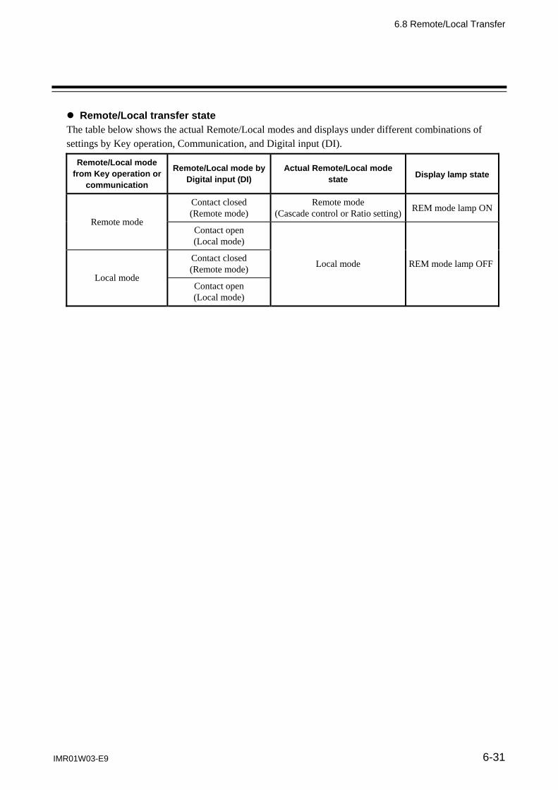
6.8 Remote/Local Transfer
IMR01W03-E9 6-31
Remote/Local transfer state The table below shows the actual Remote/Local modes and displays under different combinations of settings by Key operation, Communication, and Digital input (DI).
Remote/Local mode from Key operation or
communication
Remote/Local mode byDigital input (DI)
Actual Remote/Local mode state
Display lamp state
Remote mode
Contact closed (Remote mode)
Remote mode (Cascade control or Ratio setting) REM mode lamp ON
Contact open (Local mode)
Local mode REM mode lamp OFFLocal mode
Contact closed (Remote mode)
Contact open (Local mode)

6. OPERATION
6-32 IMR01W03-E9
6.9 Control Area Transfer
The control area transfer can be made by Digital input (optional), Communication (optional) or Area soak time other than the key operation.
For details of the Control area transfer by Communication, refer to the separate FB100/FB400/FB900 Communication Instruction Manual (IMR01W04-E).
Memory area function
Multi memory area function can store up to 8 individual sets of SVs and parameters in Parameter setting mode. One of the Areas is used for control, and the currently selected area is Control area.
Control area
Setting items Set value (SV) Event 1 set value Event 2 set value Event 3 set value Event 4 set value Control loop break alarm (LBA) time LBA deadband Proportional band [heat-side] Integral time [heat-side] Derivative time [heat-side] Control response parameter Proportional band [cool-side] Integral time [cool-side] Derivative time [cool-side] Overlap/Deadband Manual reset Setting change rate limiter (up) Setting change rate limiter (down) Area soak time Link area number
8
7
Memory area
1
2
The memory area number (Control area) can be changed at either RUN or STOP.
The memory area number stored at last is taken as Control area.
Ramp/soak control is possible by using Area soak time, Link area number and Setting change rate limiter (up/down) in Parameter setting mode. For details, refer to 6.13 Ramp/Soak Control (P. 6-50).

6.9 Control Area Transfer
IMR01W03-E9 6-33
Control area transfer by Front key operation
Only when the direct key type is Type 2, it is possible to transfer memory area by the front key operation. (Factory set value: Type 1)
For the Direct key type selection, refer to 7.5 Engineering Mode (P. 7-68).
1. Press the SET key several times at PV/SV monitor screen until Memory area transfer screen is displayed.
PV/SV monitor
Memory area number currently being set
Memory area transfer
2. Select the memory area number which needs to be changed by pressing the UP or DOWN key.
Memory area number changed
Memory area transfer
3. Press the SET key to store the new memory area number. The screen goes to the next parameter.
Memory area transfer Manipulated output value at MV transfer
4. Press the SET key several times to return to the PV/SV monitor.
After a new value is displayed on the display by using UP and DOWN keys, if no key operation is performed within 1 minute without pressing SET key, this instrument returns to the PV/SV monitor screen and the memory area number will not be changed.

6.9 Control Area Transfer
IMR01W03-E9 6-34
Control area transfer by Direct key (AREA) operation
Memory area transfer by the Direct key is possible with the Direct key type of the Engineering mode. Set “1: Type 1” to the Direct key type. (Factory set value: Type 1)
For the Direct key type selection, refer to 7.5 Engineering Mode (P. 7-68).
1. Press the AREA key at PV/SV monitor screen until Memory area transfer screen is displayed.
PV/SV monitor
Memory area number currently being set
Memory area transfer
Press the AREA key
2. Select the memory area number which needs to be changed by pressing the UP or DOWN key.
Memory area number changed
Memory area transfer Memory area transfer
3. Press the SET key to store the new memory area number. The screen return to the PV/SV monitor screen.
Memory area transfer PV/SV monitor

6.9 Control Area Transfer
IMR01W03-E9 6-35
Control area transfer by Digital input (DI) [optional]
Memory area (Control area) transfer by the Digital input is possible with the Digital input (DI) assignment of the Engineering mode.
For the Digital input (DI) assignment, refer to 7.5 Engineering Mode (P. 7-78).
Terminal configuration
Contact input from external devices or equipment should be dry contact input. If it is not dry contact input, the input should have meet the specifications below. Contact specifications: At OFF (contact open) 500 k or more At ON (contact closed) 10 or less
Digital input (DI 1 to DI 4)
DI 1 to DI 3: Area transfer input DI 4: Area set input
DI 1 31
30
32 DI 2
COM
33 DI 3
34 DI 4
Only when ZK-1165 specification was specified, memory area transfer is possible without area set input. For memory area transfer by ZK-1165 specification, refer to ZK-1165Specification (IMR01W08-E).
The table below shows the Digital input (DI) status and selected memory numbers for Control area transfer.
Digital input Memory area number
1 2 3 4 5 6 7 8 : Contact open
DI 1 : Contact closed DI 2 DI 3
Transfer timing of memory area (Control area) Select the memory area number according to the open or closed state of the contact (DI 1 to DI 3). Then, to store a new memory area number as the Control area, close the DI 4 for Memory area set.
[Example] Change the memory area number to 6 First, close the contacts between DI 1 and DI 3 and the common terminal. Next, open the contact between DI 2 and the common. Then, close the contact between DI 4 (Area set) and the common from open status (rising edge), the memory area number in the controller will change to “6.”
DI 1: Contact closed
DI 2: Contact open DI 3: Contact closed Rising edge Memory area transferContact open
Contact closed 1
DI 4 (Memory area set)
1 To make contact activation valid, it is necessary to maintain the same contact state (contact closed) for more than 200 ms.
1. Select the Memory area number 2. Change the Memory area
After the contact is closed, it takes “200 ms 1 sampling cycle 2” until the action of this instrument is actually selected. 2 Sampling cycle: The value selected by the sampling cycle of the Engineering mode. (Factory set value: 100 ms)
Control area transfer by Area soak time (Ramp/Soak Control)
When the memory area number is transferred by using the Area soak time, it is necessary to set the link area number (Parameter setting mode). For details, refer to 6.13 Ramp/Soak Control (P. 6-50).

6. OPERATION
6-36 IMR01W03-E9
6.10 Interlock Release
The Event interlock action holds the event state even if the measured value is out of the event zone after it enters the event zone once. The Interlock release can be made by Digital input (DI), or Communication (optional) other than the key operation.
To validate the Event interlock function, it is necessary to set Event interlock (EIL1 to 4) to “1: Used” in 7.5 Engineering Mode (P. 7-13).
For the Interlock release by Communication, refer to the separate FB100/FB400/FB900 Communication Instruction Manual (IMR01W04-E).
The following example shows how the Event interlock is released.
* Set an alarm lamp lighting conditions to EV1 to EV4 in the Engineering mode. The alarm (ALM) lamp islit through the OR operation of EV1 to EV4 each of which is set to "1: ALM lamp is lit". (Factory set value: ALM lamp is lit)
Event set value
Set value (SV)
With Interlock functionEvent state
(ALM lamp is lit. *)
Measured value (PV)
Not turned OFF as the Event interlock continues.
Release is valid. [Since the Measured value (PV) is in the event OFF region, Event interlock is released and becomes OFF]
Event type: Deviation high
Release is invalid.[Invalid when Measured value (PV) is in the event ON region.]
Event output (DO)
Event interlock releasescreen (ILr) state
Event interlock releaseoperation
Without Interlock functionEvent state
(ALM lamp is lit. *)
Event output (DO)
OFF OFF
OFF OFF
oFF oFF on
ON
ON
OFF OFF ON
OFF OFF ON

6.10 Interlock Release
IMR01W03-E9 6-37
Interlock release method by Front key operation
1. Press the SET key several times at PV/SV monitor screen until Interlock release screen is displayed.
PV/SV monitor
Interlock state ("on" is lit when the event occurs)
Interlock release
2. Press the DOWN key to release the interlock.
Interlock release
Interlock release state
3. Press the SET key to return the PV/SV monitor.
After a new value is displayed on the display by using UP and DOWN keys, if no key operation is performed within 1 minute without pressing SET key, this instrument returns to the PV/SV monitor screen and the interlock will not be released.

6.10 Interlock Release
IMR01W03-E9 6-38
Interlock release method by Digital input (DI)
Interlock release by the Digital input (DI) is possible with the Digital input (DI) assignment of the Engineering mode.
For the Digital input (DI) assignment, refer to 7.5 Engineering Mode (P. 7-78). Terminal configuration
Digital input (DI 5 to DI 7)
DI 7: Interlock release input Contact closed: Interlock release
DI 5 14
13
15 DI 6
COM
16 DI 7
Contact input from external devices or equipment should be dry contact input. If it is not dry contact input, the input should have meet the specifications below. Contact specifications: At OFF (contact open) 500 k or more At ON (contact closed) 10 or less
Transfer timing of Interlock release The interlock release operation is taken when DI contact is closed from the open condition (rising edge).
After the contact is closed, it takes “200 ms 1 sampling cycle 2” until the action of this instrument is actually selected. 2 Sampling cycle: The value selected by the sampling cycle of the Engineering mode. (Factory set value: 100 ms)
1 To make contact activation valid, it is necessary to maintain the same contact state (contact closed) for more than 200 ms.
Rising edge Contact open
Contact closed 1

6. OPERATION
IMR01W03-E9 6-39
6.11 Start Action at Recovering Power Failure
Hot/Cold start selection
The operation of this instrument is not affected by a power failure of 20 ms or less. The control start mode at power recovery after more than 20 ms power failure can be selected as follows.
Action when power failure
recovers
Operation mode when power failure recovers
Output value when power failure recovers
Hot start 1 Same as that before power failure Near the output value before power failure occurs
Hot start 2 Same as that before power failure Auto mode Value as a result of control computation 2
Manual mode Output limiter low 3 Cold start Manual mode Output limiter low 3
STOP start Started in the control stop (STOP) state regardless of the RUN mode before power failure. 1
Manipulated output value at STOP mode 3
Factory set value: Hot start 1 1 If changed to RUN from STOP by RUN/STOP selection after start, set to the operation mode before power failure
occurs. 2 The result of control computation varies with the control response parameter. 3 If there is no Feedback resistance (FBR) input in Position proportioning PID control, the following results.
Hot start 2 (Manual mode): No output (no control motor is driven) Cold start: No output (no control motor is driven) STOP start: In accordance with the setting of valve action at STOP.
If the Startup tuning (ST) function is executed or an automatic temperature rise is made just when the power is turned on or selection is made from STOP to RUN as one of the startup conditions, control starts at Hot start 2 even if set to Hot start 1 (factory set value). Control start mode when the controller recovers from power failure can be selected in Engineering mode. For details, refer to 7.5 Engineering Mode (P. 7-123).
Start determination point
In addition to Hot/Cold start selection, set the determination point of Hot start 1. The Start determination point becomes the deviation setting from the Set value (SV). The start state is determined according to the Measured value (PV) level [deviation from set value]
at power recovery. When a Measured value (PV) is between the determination points on the (plus) and (minus)
sides, always started from Hot start 1 when recovered. When a Measured value (PV) is out of the determination points or the Start determination point is
set at “0,” operation starts from any start state selected by Hot/Cold start.
Start determination point setting is conducted in Engineering mode. For details, refer to 7.5 Engineering Mode (P. 7-124).
Start determination point(minus side)
Start determination point (plus side)
Start determination point setting Set value (SV)
Hot start 1 Hot start 1, hot start 2, cold start,
or STOP start
Low High
Hot start 1, hot start 2, cold start, or STOP start

6. OPERATION
6-40 IMR01W03-E9
6.12 Position Proportioning PID Control
Position proportioning PID control converts the control output value of the controller into the corresponding signal to control a motor driven valve (control motor) and then performs temperature control of a controlled object by regulating fluid flow. In Position proportioning PID control of this controller, it is possible to select the presence or absence of Feedback resistance (FBR) input which monitors the degree of valve position (Specify when ordering). In addition, the direct action or reverse action can be selected.
Power supply to control motor
FB400/900
10
11
12 17
18
19
23
24
[Example]
Terminal number 17 to 19: Valid only when there is the Feedback resistance (FBR).
TC
Controlled object
Control motor
WIPER
CLOSE
OPEN
M
Liquids
OUT1 (open-side)
OUT2 (close-side)
9
The details of setting differ depending on the presence or absence of Feedback resistance (FBR) input. When there is a Feedback resistance (FBR) input: High/Low limit of valve position (limit value of FBR input) can be set.
[Output limiter high, Output limiter low] Valve position can be manually set.
[Manipulated output value (MV) setting in Manual mode] Feedback adjustment is necessary. [Feedback adjustment] Action at Feedback resistance (FBR) input error can be selected.
[Action at Feedback resistance (FBR) input error] Output value (FBR input) with the output turned on or off when the Autotuning (AT) function is
executed can be restricted. [Output value with AT turned on, Output value with AT turned off] The close-side (or open-side) output remains ON when the valve position is fully closed (or opened).
[Action at saturated output] When there is no Feedback resistance (FBR) input: Control motor operation can be restricted by the integrated output limiter. [Integrated output limiter] The UP or DOWN key is used to output opening or closing signal in Manual mode.
UP key (open-side): While the UP key is being pressed, open-side output (OUT1) is output continuously. Releasing the UP key turns off the open-side output to hold the opened state at that time.
DOWN key (close-side): While the DOWN key is being pressed, close-side output (OUT2) is output continuously. Releasing the DOWN key turns off the close-side output to hold the opened state at that time.
For Manual operation in Position proportioning PID control, refer to 6.7 Auto/Manual Transfer (P. 6-27).

6.12 Position Proportioning PID Control
IMR01W03-E9 6-41
Parameter valid/invalid depending on the presence or absence of Feedback resistance (FBR) input (×: Valid, : Invalid)
Parameter (Engineering mode)
With Feedback resistance (FBR) input
Without Feedback resistance (FBR) input
Manipulated output value (MV) at STOP mode (rMV1 ) [Function block 51]
×
Output limiter high (oLH ) Output limiter low (oLL ) [Function block 51]
×
Output value with AT turned on (ATon ) Output value with AT turned off (AToF ) [Function block 52]
×
Open/Close output neutral zone (Ydb ) * [Function block 53] × ×
Open/Close output differential gap (YHS )* [Function block 53] × ×
Action at feedback resistance (FBR) input error (Ybr ) [Function block 53]
×
Feedback adjustment (PoS ) [Function block 53] ×
Control motor time (MoT ) * [Function block 53] × ×
Integrated output limiter (oLA ) [Function block 53] ×
Valve action at STOP (VAL ) * [Function block 53] × ×
Action at saturated output (YASo ) [Function block 53] ×
* These parameters are necessary to set regardless of the presence or absence of Feedback resistance (FBR) input.
Position proportioning PID control can be performed if two output points are selected when ordering.
Startup tuning (ST) cannot be executed by Position proportioning PID control. In addition, the Output change rate limiter also becomes invalid.

6.12 Position Proportioning PID Control
IMR01W03-E9 6-42
Setting flowchart This section describes the Position proportioning PID control dedicated setting items and the setting items which are effective when there is or is not a Feedback resistance (FBR) input. The following setting items are all set in the Engineering mode.
Select the Control action
Set the Manipulated output value (MV) at STOP mode
Set the Output limiter
Set the output value with AT turned on/off
Set the Open/Close output neutral zone
Set the Open/Close output differential gap
Set the action at Feedback resistance (FBR) input error
Set the valve position at control STOP. [Effective when there is a Feedback resistance (FBR) input]
Select the Position proportioning PID control (direct/reverse action).[Position proportioning PID control common setting]
Set the high-limit/low-limit value of the valve position. [Effective when there is a Feedback resistance (FBR) input]
Set the upper limit and lower limit values of the valve position which is opened and closed by output ON/OFF at Autotuning (AT) execution. [Effective when there is a Feedback resistance (FBR) input]
Set the output OFF zone between open-side and close-side outputs. [Position proportioning PID control common setting]
Set the differential gap of open-side and close-side outputs. [Position proportioning PID control common setting]
Set the action at Feedback resistance (FBR) input error. [Effective when there is a Feedback resistance (FBR) input]
Continued on the next page.
Position proportioning PID control common setting
Effective when there is a Feedback resistance (FBR) input
Effective when there is not a Feedback resistance (FBR) input
Set when you want to limit the position of the valve whichis opened and closed by output ON/OFF at Autotuning(AT) execution.

6.12 Position Proportioning PID Control
IMR01W03-E9 6-43
Set the Integrated output limiter which integrates the output and sets the output to OFF when the result reached the set value when an open-side (or close-side) output is outputted continuously. [Effective when there is not a Feedback resistance (FBR) input]
Set the action of open-side and close-side outputs at control STOP. [Position proportioning PID control common setting]
Set the Integrated output limiter
Set the Valve action at STOP
Set the Control motor time
Set the Control motor time required for rotation from the fully closed position to the fully opened position. [Position proportioning PID control common setting]
Continued from the previous page.
Feedback adjustment Adjust the Feedback resistance (FBR) input. [Effective when there is a Feedback resistance (FBR) input]
Action at saturated output Set to maintain ON state for the close-side (or open-side) output when the valve position is fully closed (or opened). [Effective when there is a Feedback resistance (FBR) input]

6.12 Position Proportioning PID Control
IMR01W03-E9 6-44
Setting procedures
When there is a Feedback resistance (FBR) input
1. When set the parameter in Engineering mode, change the operation mode from RUN mode to STOP mode.
To change from STOP mode to RUN mode, refer to 6.4 RUN/STOP Transfer (P. 6-11).
2. Press the Shift key while pressing the SET key for 2 seconds at PV/SV monitor screen until Engineering mode is displayed. Function block 10 screen is displayed first.
PV/SV monitor
Function block 10 (Engineering mode)
Press the shift key while pressing the SET key for 2 seconds
3. Press the UP or DOWN key until Function block 51 screen is displayed.
Function block 10 (Engineering mode)
Function block 51 (Engineering mode)
4. Press the SET key to change the control action setting screen.
Function block 51 (Engineering mode)
Control action (Function block 51)

6.12 Position Proportioning PID Control
IMR01W03-E9 6-45
5. Press the UP key to change the control action from “1: PID control (reverse action)” to “5: Position
proportioning PID control (reverse action).” Then, press the SET key to store the new value.
Control action (Function block 51)
6. Set the following parameters Manipulated output value (MV1) at STOP mode, Output limiter high (MV1), and Output limiter low (MV1) in the same way as described above. Manipulated output value (MV1) at STOP mode [Function block 51]
Output limiter high (MV1) [Function block 51]
Output limiter low (MV1) [Function block 51]
Set the valve position at control STOP. Setting range: 5.0 to 105.0 % (Factory set value: 5.0)
Set the high-limit value of the valve position. Setting range: Output limiter low (MV1) to 105.0 % (Factory set value: 105.0)
Set the low-limit value of the valve position. Setting range: 5.0 % to Output limiter high (MV1) (Factory set value: 5.0)

6.12 Position Proportioning PID Control
IMR01W03-E9 6-46
7. Set the parameters Output value with AT turned on and Output value with AT turned off after
changing to the Function block 52 screen by key operation. Set when you want to limit the position of the valve which is opened and closed by output ON/OFF at Autotuning (AT) execution.
Output value with AT turned on [Function block 52]
Output value with AT turned off [Function block 52]
8. Set the following parameters after changing to the Function block 53 screen. Also, execute the feedback adjustment of the Feedback resistance (FBR) input. Open/Close output neutral zone Open/Close output differential gap Action at Feedback resistance (FBR) input error Control motor time Valve action at STOP Action at saturated output
The parameter display order is shown below. Open/Close output neutral zone Open/Close output differential gap Action at Feedback resistance (FBR) input error Feedback adjustment Control motor time Valve action at STOP Action at saturated output
Open/Close output neutral zone [Function block 53]
Continued on the next page.
Set the lower limit values of the valve position (Feedback resistance input) which is opened and closed by output ON/OFF at Autotuning (AT) execution. Setting range: 105.0 % to Output value with AT turned on (Factory set value: 105.0) However, within output limiter
Set the upper limit values of the valve position (Feedback resistance input) which is opened and closed by output ON/OFF at Autotuning (AT) execution. Setting range: Output value with AT turned off to 105.0 % (Factory set value: 105.0) However, within output limiter
Set the output OFF zone between open-side and close-side outputs. Setting range: 0.1 to 10.0 % of output (Factory set value: 2.0)

6.12 Position Proportioning PID Control
IMR01W03-E9 6-47
Continued from the previous page. Open/Close output differential gap [Function block 53]
Action at Feedback resistance (FBR) input error [Function block 53]
Control motor time [Function block 53]
Valve action at STOP [Function block 53]
Action at saturated output [Function block 53]
Continued on the next page.
Set the differential gap of open-side and close-side outputs. Setting range: 0.1 to 5.0 % of output (Factory set value: 1.0)
Set the action at Feedback resistance (FBR) input error. Setting range: 0: Depending on the valve action at STOP 1: Control action continued (Factory set value: 0)
Set the Control motor time required for rotation from the fully closed position to the fully opened position. Setting range: 5 to 1000 seconds (Factory set value: 10)
Set the action of open-side and close-side outputs at control STOP. Setting range: 0: Close-side output OFF, Open-side output OFF 1: Close-side output ON, Open-side output OFF 2: Close-side output OFF, Open-side output ON (Factory set value: 0)
If Feedback adjustment is performed, the control motor drivingtime is automatically computed. However, if the time thuscomputed is less than 5 seconds, no set value is updated.
For the feedback adjustment, refer to the next page.
Set to maintain ON state for the close-side (or open-side) output when the valve position is fully closed (or opened). Setting range: 0: Invalid (The close-side [or open-side] output turns to OFF when the valve position is fully closed [or opened]). 1: Valid (The close-side [or open-side] output remains ON state when the valve position is fully closed [or opened]). (Factory set value: 0)

6.12 Position Proportioning PID Control
IMR01W03-E9 6-48
Continued from the previous page.
Feedback adjustment [Function block 53]
At the adjustment preparation screen, press and hold the Shift key for 5 seconds to start the adjustment. The display automatically return to the adjustment preparation screen after the adjustment is completed.
Display returns to the PV/SV monitor screen if no key operation is performed within 1 minute (except during the Feedback adjustment).
9. At the end of setting of each parameter and Feedback adjustment of the Feedback resistance
(FBR) input, return to the PV/SV monitor screen and then refer to 6.4 RUN/STOP Transfer (P.6-11) and set to the control RUN state.
Adjust the Feedback resistance (FBR) input. After the adjustment, the manipulated output value from 0 to 100 % obtained after PID computation matches the valve position signal of the fully closed position to the fully opened position [Feedback resistance (FBR) input] sent from the control motor.
Adjustment preparation screen
Press the Shift key for 5 seconds
Automatically
Adjustment screen for open direction.
Adjustment screen for closed direction.
(Adjustment end)
Automatically

6.12 Position Proportioning PID Control
IMR01W03-E9 6-49
When there is no Feedback resistance (FBR) input
1. Refer to steps 1 to 5 (P. 6-44 to P. 6-45) of When there is a Feedback resistance (FBR) input and set the control action to Position proportioning PID control (direct or reverse action).
2. Refer to step 8 (P. 6-46) of When there is a Feedback resistance (FBR) input and set the
Open/Close output neutral zone, Open/Close output differential gap, Control motor time, and Valve action at STOP. In addition, also set Integrated output limiter.
The parameter display order is shown below. Open/Close output neutral zone Open/Close output differential gap Control motor time Integrated output limiter Valve action at STOP
Integrated output limiter [Function block 53]
Since the output is integrated when the open-side (or close-side) output is outputted continuously, once the inverted output is outputted, the integrated value is reset.
[Example] If control is started at the fully closed state when the Control motor operation time is set at 10 seconds and the Integrated output limiter value is set at 100 %, the following results.
3. At the end of setting of each parameter, return to the PV/SV monitor screen and then refer to 6.4 RUN/STOP Transfer (P. 6-11) and set to the control RUN state.
Set the Integrated output limiter which integrates the output and sets the output to OFF when the result reached the set value when an open-side (or close-side) output is outputted continuously. Setting range: 0.0 to 200.0 % of control motor time 0.0: Integrated output limiter function OFF (Factory set value: 150.0)
Open-side output 3 seconds
(Open-side integrated value 30 %)
Open-side output 5 seconds
(Open-side integrated valuE90 %)
STOP STOP
Close-side output 2 seconds Close-side integrated value reset
(New close-side integrated value becomes 20 %.)

6. OPERATION
6-50 IMR01W03-E9
6.13 Ramp/Soak Control
Ramp/Soak control of this instrument realizes simple Ramp/Soak control by linking a number of memory areas having different Set values (SV). Simple Ramp/Soak control is possible by setting a Set value (SV), Setting change rate limiter (up/down), Area soak time, and Link area number in each memory area.
Set value (SV): Sets the fixed set point control (control by fixed set value) desired value of each memory area.
Setting change rate limiter: Sets the slope of the Set value (SV) which is raised or lowered at each unit time.
Area soak time: Sets the fixed set point control time of each memory area. Link area number: Sets the memory area numbers for linking the corresponding memory areas.
Besides the above, the Setting change rate limiter unit time and Area soak time unit are set in the Engineering mode.
Example: Ramp/Soak control by linking Memory area 1 to 3
SV of area 3
Ambient temp.
Soak time of Area 1
Measured value (PV)
Time
Soak time of Area 2
Soak time * of Area 3
Area 1 (2)
Area 2(3)
Area 3 (OFF)
Setting change rate limiter (up) setting of Area 1
Setting change rate limiter (up) setting of Area 2
Setting change rate limiter (down) setting of Area 3
SV of area 1
SV of area 2
* As the area soak time for memory area linked last becomes invalid, the state of SV3 reached continues.
Memory area (Link area number)

6.13 Ramp/Soak Control
IMR01W03-E9 6-51
Operation flowchart
Study of Ramp/Soak content
Set the Setting change rate limiter unit time
Set the Soak time unit
Set the Setting change rate limiter
Set the Area soak time
Set the Link area number
Set the Set value (SV)
Refer to Settings before operation (P. 6-52), Operation procedures (P. 6-55).
The Ramp/Soak control contents are studied, and the operation status is graphed, and the set values are summarized in a table in advance.
Check the Control area
Ramp/Soak control start
Refer to Settings before operation (P. 6-52), Operation procedures (P. 6-55).
Refer to Operation procedures (P. 6-55). Set at each memory area.
Refer to Operation procedures (P. 6-55). Set at each memory area.
Refer to Operation procedures (P. 6-55). Set at each memory area.
Refer to Operation procedures (P. 6-55). Set at each memory area.
Refer to Operation procedures (P. 6-55). The start area is made the Control area before the start of Ramp/Soak control.
Refer to Operation procedures (P. 6-55). Changes from the STOP mode to the RUN mode, and starts Ramp/Soak control.
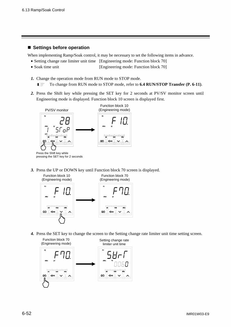
6.13 Ramp/Soak Control
IMR01W03-E9 6-52
Settings before operation
When implementing Ramp/Soak control, it may be necessary to set the following items in advance. Setting change rate limiter unit time [Engineering mode: Function block 70] Soak time unit [Engineering mode: Function block 70]
1. Change the operation mode from RUN mode to STOP mode.
To change from RUN mode to STOP mode, refer to 6.4 RUN/STOP Transfer (P. 6-11).
2. Press the Shift key while pressing the SET key for 2 seconds at PV/SV monitor screen until Engineering mode is displayed. Function block 10 screen is displayed first.
PV/SV monitor
Function block 10(Engineering mode)
Press the Shift key while pressing the SET key for 2 seconds
3. Press the UP or DOWN key until Function block 70 screen is displayed.
Function block 10 (Engineering mode)
Function block 70 (Engineering mode)
4. Press the SET key to change the screen to the Setting change rate limiter unit time setting screen.
Function block 70 (Engineering mode)
Setting change rate limiter unit time
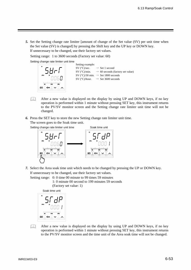
6.13 Ramp/Soak Control
IMR01W03-E9 6-53
5. Set the Setting change rate limiter [amount of change of the Set value (SV) per unit time when
the Set value (SV) is changed] by pressing the Shift key and the UP key or DOWN key. If unnecessary to be changed, use their factory set values. Setting range: 1 to 3600 seconds (Factory set value: 60)
Setting change rate limiter unit time Setting example: SV (C)/sec. → Set 1 second SV (C)/min. → 60 seconds (factory set value) SV (C)/30 min. → Set 1800 seconds SV (C)/hour. → Set 3600 seconds
After a new value is displayed on the display by using UP and DOWN keys, if no key operation is performed within 1 minute without pressing SET key, this instrument returns to the PV/SV monitor screen and the Setting change rate limiter unit time will not be changed.
6. Press the SET key to store the new Setting change rate limiter unit time. The screen goes to the Soak time unit.
Setting change rate limiter unit time Soak time unit
7. Select the Area soak time unit which needs to be changed by pressing the UP or DOWN key. If unnecessary to be changed, use their factory set values. Setting range: 0: 0 time 00 minute to 99 times 59 minutes 1: 0 minute 00 second to 199 minutes 59 seconds (Factory set value: 1)
Soak time unit
After a new value is displayed on the display by using UP and DOWN keys, if no key operation is performed within 1 minute without pressing SET key, this instrument returns to the PV/SV monitor screen and the time unit of the Area soak time will not be changed.

6.13 Ramp/Soak Control
IMR01W03-E9 6-54
8. Press the SET key to store the new time unit of the Area soak time.
The screen returns to the first parameter (Function block 70). Soak time unit Function block 70
9. To return the PV/SV monitor, press the MONI key (for direct key type 1), or press the Shift key while pressing the SET key.

6.13 Ramp/Soak Control
IMR01W03-E9 6-55
Operation procedures
This section uses the following sample of Ramp/Soak control to describe the operation procedures. [Example: Ramp/Soak control by linking Memory area 1 to 3]
SV of Area 3[50. 0 C]
[Example: 25.0 C]
Soak time of Area 1
[30 min.]
Measured value (PV)
Time
Soak time of Area 2
[40 min.]
Soak time * of Area 3
Area 1 (2)
Area 2(3)
Area 3 (OFF)
Setting change rate limiter (up) setting of Area 1 [4.0 C/min.]
Setting change rate limiter (down) setting of Area 3 [9.0 C/min.]
SV of Area 1[150. 0 C]
SV of Area 2[200. 0 C]
Memory area (Link area number)
(Ambient temp.)
Setting change rate limiter (up) setting of Area 2 [2.0 C/min.]
Area 1 Area 2 Area 3
Set value (SV) 150.0 C 200.0 C 50.0 C
Setting change rate limiter (up) [SVrU] 4.0 C/min. (60 sec.) 2.0 C/min. (60 sec.) OFF
Setting change rate limiter (down) [SVrd] OFF OFF 9.0 C/min. (60 sec.)
Area soak time [AST] 30 min. 40 min. 0 min. *
Link area number [LnKA] 2 3 OFF
* In this example, the Area soak time for memory area 3 is set. However, as the Area soak time for the memory area linked last becomes invalid, the state of SV3 reached continues.
The Ramp/Soak control contents are studied and Ramp/Soak status is graphed and the set values of each memory area are summarized in a table as shown above. Refer to Settings before operation (P. 6-52) and set the Setting change rate limiter unit time and Area soak time (In this example, the factory set values are used for both). Since control stops (STOP) at this time, go directly to the next step. ・Setting change rate limiter unit time (SVrT): 60 seconds [factory set value] ・Soak time unit (STdP): 1 (0 minutes 00 seconds to 199 minutes 59 seconds) [factory set value]
Step 1: Study the Ramp/Soak control content.
Step 2: Set the Setting change rate limiter unit time and Soak time unit of function block 70.

6.13 Ramp/Soak Control
IMR01W03-E9 6-56
1. Press the SET key at Parameter setting mode until Setting change rate limiter (up) setting screen is displayed.
2. Press the UP key to change the number to 4.0. 3. Press the SET key to store the new value. The
display goes to the next parameter. Check that this screen is set to OFF.
4. Press the SET key until Area soak time setting
screen is displayed.
5. Press the Shift key to high-light the tens place of “minute.”
6. Press the UP key to change the number to 3. 7. Press the SET key to store the new value.
The display goes to the next parameter. 8. Press the UP key and change the Memory area 1
Link area number to 2. 9. Press the SET key to store the new value.
The display goes to the next parameter.
Step 3: Set the Setting change rate limiter, Area soak time and Link area number to each of Memory area 1, 2 and 3.
Factory set value: OFF (Unused)
Factory set value: OFF (Unused)
Factory set value: 0 min. 00 sec.
Factory set value: OFF (No link)
High-light

6.13 Ramp/Soak Control
IMR01W03-E9 6-57
10. Set the Memory area 2. Press the SET key several times until Setting change rate limiter (up) setting screen is displayed. The screen set at step 2 (P. 6-56) is displayed.
11. Press the Shift key until Memory area display unit
is high-lighted. 12. Press the UP key to change to 2. Area number
display flashes. * 13. Press the Shift key to high-light the least significant
digit.
14. Set the Memory area 3 Setting change rate limiter, Area soak time, and Link area number by the same procedures as described in steps 3 to 9 (P. 6-56).
15. Set the Memory area 3. Press the SET key several times until Setting change rate limiter (up) setting screen of the Memory area 2 is displayed.
16. Press the shift key to high-light (flashing) the
Memory area display unit. 17. Press the UP key to change to 3. Area number
display flashes. 18. Set the Memory area 3 Setting change rate limiter,
Area soak time, and Link area number by the same procedures as described in steps 3 to 9 (P. 6-56). However, in the case of this Ramp/Soak control sample, the area soak time is invalid, even if set, because Memory area 3 is linked last.
* The area number display flashes to indicate that the area number now displayed differs from the control area.
High-light
Factory set value: OFF (Unused)
Flashing
Flashing High-light
Flashing
High-light(Flashing)
Factory set value: OFF (Unused)
Flashing

6.13 Ramp/Soak Control
IMR01W03-E9 6-58
1. Press and hold the SET key for 2 seconds to
change the mode from Parameter setting mode to SV setting & monitor mode. PV/SV monitor screen is displayed.
Changed to the SV setting & monitor mode even if the Shift key is pressed while pressing the SET key. When the Direct key is type 1, the mode can also be changed to the SV setting & monitor mode by pressing the MONI key.
2. Press the SET key until Set value (SV) setting
screen of Memory area 1 is displayed. 3. Press the Shift key to high-light the tens place. 4. Press the UP key to change the number to 5.
5. Press the SET key to store the new value. The display goes to the next parameter.
6. Set the Set value (SV) of Memory area 2.
Press the SET key several times until Set value (SV) setting screen of Memory area 1 is displayed. The screen set at step 4 (P. 6-58) is displayed.
7. Press the Shift key to high-light the Memory area
display unit.
8. Press the UP key to change the number to 2. The
number in AREA (Area number) display flashes.
9. Press the Shift key to high-light the hundreds place.
10. Hereinafter, set the Memory areas 2 and 3 Set
value (SV) by the same procedure.
Step 4: Set the SV to each of Memory area 1, 2 and 3.
Example: Manipulated output value at MV transfer screen
High-light
Flashing
Flashing
High-light
STOP display because control is stopped
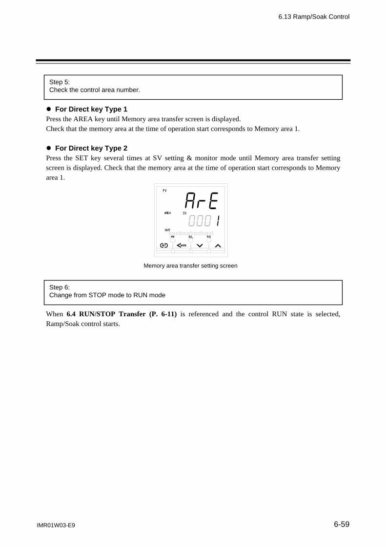
6.13 Ramp/Soak Control
IMR01W03-E9 6-59
For Direct key Type 1 Press the AREA key until Memory area transfer screen is displayed. Check that the memory area at the time of operation start corresponds to Memory area 1. For Direct key Type 2 Press the SET key several times at SV setting & monitor mode until Memory area transfer setting screen is displayed. Check that the memory area at the time of operation start corresponds to Memory area 1. When 6.4 RUN/STOP Transfer (P. 6-11) is referenced and the control RUN state is selected, Ramp/Soak control starts.
Step 5: Check the control area number.
Step 6: Change from STOP mode to RUN mode
Memory area transfer setting screen

6. OPERATION
6-60 IMR01W03-E9
6.14 Group Operation by the Intercontroller Communication
Intercontroller communication exchanges data between multiple FB400/900 (hereinafter referred to as “controller”) without using remote setting input and analog output and other analog signals and host computer communications. The following four functions become usable when the Intercontroller communication is used. Group RUN/STOP function Automatic temperature rise function (with learning function)
Since Intercontroller communication communicates by connecting multiple controllers
(FB400/900), a time lag (maximum 70 ms number of controllers connected) is always generated. Therefore, it may be impossible to cope with rapid response control systems. When performing Intercontroller communication, consider the operation delay caused by the time lag.
Since Intercontroller communication recognizes the connected controllers when the power is turned OFF ON, be sure that power to all the controllers engaged in Intercontroller communication is turned ON at the same time.
6.14.1 Wiring method of the Intercontroller communication In Intercontroller communication, perform multi-drop connection using the communication 2 port (COM2). Communication terminal number and signal details
Terminal No. Signal name Symbol
25 Signal ground SG
28 Send data/Receive data T/R (A)
29 Send data/Receive data T/R (B) Wiring method
FB400/900 Communication terminals
(COM2 side)
Maximum connections: 32 instruments
*R: Termination resistors (Example: 120 , 1/2 W)
25
T/R (B)
T/R (A)
28 29
SG
*R
25
T/R (B)
T/R (A)
28 29
SG
25
T/R (B)
T/R (A)
28 29
SG
*R
FB400/900 Communication terminals
(COM2 side)
FB400/900 Communication terminals
(COM2 side)
RS-485 Paired wire
Shielded twisted pair wire
RS-485 Paired wire
Shielded twistedpair wire
FB400/900 FB400/900 FB400/900 FB400/900 FB400/900
Maximum connections:32 instruments
Cascade control function Ratio setting function
CAUTION

6.14 Group Operation by the Intercontroller Communication
IMR01W03-E9 6-61
6.14.2 Common setting of the Intercontroller communication
When performing Intercontroller communication, Device address 2 must be set for all the controllers engaged in the Intercontroller communication. Set the Device address 2
1. Press the Shift key while pressing the SET key at PV/SV monitor screen until Setup setting mode is displayed. The screen displayed first differs depending on the specification.
PV/SV monitor
Heater break alarm 1 (HBA1) set value(Setup setting mode)
When there is CT1 input
Press the Shift key while pressing the SET key
2. Press the SET key until Device address 2 screen is displayed.
Device address 2
When there is CT1 input
Heater break alarm 1 (HBA1) set value (Setup setting mode)
3. Set the address by pressing the UP or DOWN keys. Setting range: 0 to 31 (Factory set value: 0)
Device address 2
After a new value is displayed on the display by using UP and DOWN keys, if no key operation is performed within 1 minute without pressing SET key, this instrument returns to the PV/SV monitor screen and the address will not be changed.
Always set the address ofeach controller to the numberin succession starting from 0.

6.14 Group Operation by the Intercontroller Communication
IMR01W03-E9 6-62
4. Press the SET key to store the new address. The screen goes to the next parameter.
Device address 2 Set lock level
5. To return the PV/SV monitor, press the MONI key (for Direct key Type 1), or press the Shift key while pressing the SET key.
6. Set the address of the other controllers by the same procedures as described in steps 1 to 5 above.
When performing Intercontroller communication, the Communication 2 protocol (Engineering mode: function block 60) setting must be “2: Intercontroller communication.” Since the Communication 2 protocol shipping value is “2: Intercontroller communication,” resetting is unnecessary. However, when Intercontroller communication cannot be executed successfully, check the Communication 2 protocol setting.
When Intercontroller communication is performed, the setup screen related to communication 2 other than Device address 2 (Communication speed 2, Data bit configuration 2, and Interval time 2) is not displayed.

6.14 Group Operation by the Intercontroller Communication
IMR01W03-E9 6-63
6.14.3 Group RUN/STOP function
The group RUN/STOP function makes multiple controllers one group and if even one controller in the group is set to the RUN/STOP state, it places all the controllers in that group into the RUN/STOP state.
When executing group RUN/STOP at Intercontroller communication, a time lag (maximum 70 ms number of controllers connected) up to actual transfer after operation is generated. For example, when RUN/STOP operation is repeated by different controllers in a short time, the last operation and actual controller state may be different. Therefore, be especially careful of the RUN/STOP transfer timing.
The group RUN/STOP function by Intercontroller communication can be executed when the Communication 2 port (COM2) is usable.
The maximum number of connectable controllers at Intercontroller communication is 32, without regard to the number of groups.
When the group RUN/STOP function is used at automatic temperature rise by Intercontroller communication, all the controllers in the group can start temperature rise simultaneously.
Operation flowchart
For each status by RUN/STOP operation, refer to Group RUN/STOP operation and states (P. 6-64) and Usage example (P. 6-69).
Set the RUN/STOP group
Group control stop
Refer to Settings before operation (P. 6-65).
If even one of the controllers in the same RUN/STOP groupenters the STOP state, all the controllers of the same group enterthe STOP state.
Group control start
If even one of the controllers in the STOP state is set to RUN, allthe controllers set at the same group enter the RUN state. However, when there is also a controller whose Digital input (DI)becomes STOP, the group does not enter the RUN state.
Set the Device address 2 Refer to 6.14.2 Common setting of the Intercontroller
communication (P. 6-61).
Set the Digital input (DI) assignment Refer to Settings before operation (P. 6-65).

6.14 Group Operation by the Intercontroller Communication
IMR01W03-E9 6-64
Requirements for Group RUN/STOP
Control stop (STOP) by group RUN/STOP condition If there is even one controller in the same group, when STOP is selected by Key operation, Communication, or Digital input (DI), it enters the STOP state. Control start (RUN) by group RUN/STOP condition If there is even one controller in the same group, when RUN is selected by Key operation, Communication, or Digital input (DI), it enters the RUN state. However, if there is even one controller whose Digital input (DI) becomes STOP, it does not enter the RUN state.
When RUN/STOP selection by Digital input (DI) and RUN/STOP selection by key operation or communication are different, the STOP state is entered. (STOP priority)
Group RUN/STOP operation and states
The actual RUN/STOP state is different for RUN/STOP by Key operation, Digital input, and Communications. The following shows the relationship between each operation and the actual RUN/STOP state.
When there is no RUN/STOP transfer by the digital input (DI)]
RUN/STOP mode from key operation or communication
Actual RUN/STOP mode state
State of STOP character display
STOP STOP STOP (SToP)
RUN RUN STOP is not displayed
When there is RUN/STOP transfer by the digital input (DI)
RUN/STOP mode from key operation or
communication
RUN/STOP mode by Digital input (DI)
Actual RUN/STOP mode state
State of STOP character display
STOP Contact open (STOP)
STOP
STOP (SToP)
Contact closed (RUN) KSTP (KSTP)
RUN Contact open (STOP) dSTP (dSTP)
Contact closed (RUN) RUN STOP is not displayed
Other than those above, the actual RUN/STOP state and STOP display may be different, depending on the RUN/STOP state by Digital input (DI) of the other controllers in the same group.
RUN/STOP mode from key operation or communication
RUN/STOP modeby Digital input (DI)
RUN/STOP selection by digital input (DI) of
other controllers in the same group.
Actual RUN/STOP mode state
State ofSTOP
characterdisplay
RUN Contact close (RUN)
or Without DI
STOP STOP GSTP(GSTP)
Refer to Usage example (P. 6-69).

6.14 Group Operation by the Intercontroller Communication
IMR01W03-E9 6-65
Settings before operation
When implementing the group RUN/STOP function, the following items must be set. Device address 2 [Setup setting mode] Digital input (DI) assignment [Engineering mode: Function block 23] RUN/STOP group [Engineering mode: Function block 55]
For the Device address 2 setting, refer to 6.14.2 Common setting of the Intercontroller communication (P. 6-61).
1. Change the operation mode from RUN mode to STOP mode.
To change from RUN mode to STOP mode, refer to 6.4 RUN/STOP Transfer (P. 6-11).
2. Press the Shift key while pressing the SET key for 2 seconds at PV/SV monitor screen until Engineering mode is displayed. The Function block 10 screen is displayed first.
PV/SV monitor
Function block 10(Engineering mode)
Press the Shift key while pressing the SET key for 2 seconds
3. Press the UP or DOWN key until Function block 23 screen is changed.
Function block 10 (Engineering mode)
Function block 23 (Engineering mode)

6.14 Group Operation by the Intercontroller Communication
IMR01W03-E9 6-66
4. Press the SET key to change the Digital input (DI) assignment screen.
Function block 23 (Engineering mode) Digital input (DI) assignment
5. Set the Digital input (DI) assignment by pressing the UP or DOWN keys. When performing RUN/STOP transfer by Digital input (DI), set “6.” Set “2,” “3,” or “4” only when using with functions other than RUN/STOP transfer. Setting range: 1 to 8 (Factory set value: 1)
Digital input (DI) assignment
Set value DI 1 DI 2 DI 3 DI 4 DI 5 DI 6 DI 7
1
Memory area number selection (1 to 8)
Memory area set
Unused
2 RUN/STOP REM/LOC AUTO/MAN
3 RUN/STOP REM/LOC
Interlock release
4 RUN/STOP AUTO/MAN
5 REM/LOC AUTO/MAN
6 RUN/STOP
Unused 7 REM/LOC
8 AUTO/MAN
When performing group RUN/STOP transfer by Digital input (DI), wiring conservation and simple operation are possible by setting “RUN/STOP transfer by Digital input (DI)” for only one controller in the group. After a new value is displayed on the display by using UP and DOWN keys, if no key operation is performed within 1 minute without pressing SET key, this instrument returns to the PV/SV monitor screen and the Digital input (DI) assignment will not be changed. For the Digital input (DI) assignment, refer to 7.5 Engineering Mode (P. 7-78).

6.14 Group Operation by the Intercontroller Communication
IMR01W03-E9 6-67
6. Press the SET key to store the new Digital input (DI) assignment. The screen goes to the
Function block 23 screen.
Digital input (DI) assignment Function block 23
7. Press the UP or DOWN key until Function block 55 screen is displayed.
Function block 55 (Engineering mode)
Function block 23 (Engineering mode)
8. Press the SET key until RUN/STOP group setting screen is displayed.
Function block 55 (Engineering mode) RUN/STOP group

6.14 Group Operation by the Intercontroller Communication
IMR01W03-E9 6-68
9. Set the RUN/STOP group number by pressing the UP or DOWN keys.
Setting range: 0 to 16 (Factory set value: 0)
RUN/STOP group
When the group number is set to “0,” the group RUN/STOP state of that controller becomes OFF. After a new value is displayed on the display by using UP and DOWN keys, if no key operation is performed within 1 minute without pressing SET key, this instrument returns to the PV/SV monitor screen and the RUN/STOP group number will not be changed.
10. Press the SET key to store the new RUN/STOP group number. The screen goes to the next
parameter.
RUN/STOP group Automatic temperature rise dead time
11. To return the PV/SV monitor, press the MONI key (for direct key type 1), or press the Shift key while pressing the SET key.
12. Set Digital input (DI) assignment and RUN/STOP group number of other controllers by the same
procedure as that described in steps 1 to 11 above.

6.14 Group Operation by the Intercontroller Communication
IMR01W03-E9 6-69
Usage example
When performing RUN/STOP by making 3 controllers one group.
Connection status of the Intercontroller communication
The parts which become “DI” in the following description specify “RUN/STOP transfer by digital input (DI).”
Example 1: RUN/STOP by key operation
The following key operations perform the same action whether or not there is DI. The display at STOP is different when there is and when there isn’t DI.
[When all 3 controllers do not have DI]
1. When controller No. 1 to 3 are in the RUN state, if any one of the controllers is placed into the STOP state by key operation, all the controllers in that group enter the STOP state.
2. If any one of controller No. 1 to 3 is placed into the RUN state by key operation, all the controllers in that group enter the RUN state.
[When only controller No. 1 has DI]
1. When controller No. 1 to 3 are in the RUN state, if any one of the controllers is placed into the STOP state by key operation, all the controllers in that group enter the STOP state.
2. If any one of controller No. 1 to 3 is placed into the RUN state by key operation, all the controllers in that group enter the RUN state.
STOP display at control STOP
Controller No. 1
(Group No.1)
Controller No. 2
(Group No.1)
Controller No. 3
(Group No.1)
Controller No. 1 (No DI)
Controller No. 2 (No DI)
Controller No. 3 (No DI)
Controller No. 1 (DI)
Controller No. 2 (No DI)
Controller No. 3 (No DI)
Display when stoppedby key operation
STOP display at control STOP

6.14 Group Operation by the Intercontroller Communication
IMR01W03-E9 6-70
[When controller No. 1 and No. 2 have DI]
1. When controller No. 1 to 3 are in the RUN state, if any one of the controllers is placed into the STOP state by key operation, all the controllers in that group enter the STOP state.
2. If any one of controller No. 1 to 3 is placed into the RUN state by key operation, all the controllers in that group enter the RUN state.
Example 2: RUN/STOP by DI
[When controller No. 1 has DI] (Controller No. 2, 3: May have or not have DI)
1. When controller No. 1 to 3 are in the RUN state, if the Digital input (DI) of controller No. 1 is transferred to the STOP state (contact closed contact open), all the controllers in that group enter the STOP state.
When stopped by DI, that group does not enter the RUN state as long as the operated DI is not set to RUN. Therefore, the STOP display is changed so that the controller that operated DI is known.
2. When the Digital input (DI) of controller No. 1 is transferred to the RUN state (contact open
contact closed), all the controllers of the same group enter the RUN state.
When performing group RUN/STOP transfer by Digital input (DI), wiring conservation and simple operation are possible by setting “RUN/STOP transfer by Digital input (DI)” for only one controller in the group.
Controller No. 3 (Same whether
DI or no DI)
Controller No. 1 (DI)
Controller No. 2 (Same whether
DI or no DI)
Display when stoppedby DI
Display when stopped by DI of another controller in the same group
Display when stopped by DI of another controller in the same group
STOP display at control STOP
Controller No. 2 (DI)
Controller No. 1 (DI)
Controller No. 3 (No DI)
Display when stoppedby key operation
Display when stoppedby key operation
STOP display at control STOP

6.14 Group Operation by the Intercontroller Communication
IMR01W03-E9 6-71
When RUN/STOP by key operation and RUN/STOP by DI overlapped, the following occurs.
[When stopped by DI after STOP by key operation]
Thereafter, when the Digital input (DI) of controller No. 1 is transferred to STOP, the STOP display changes while the STOP state remains unchanged. (When only controller No. 1 has DI)
To transfer from this state to the RUN state, the following operations are necessary. The Digital input (DI) of controller No. 1 is transferred to the RUN state.
(Contact open Contact closed) Any one of controller No.1 to 3 is set to the RUN state by key operation.
STOP display at control STOP
Controller No. 1 (DI)
Controller No. 2 (No DI)
Controller No. 3 (No DI)
Display when stoppedby key operation
Controller No. 3 (No DI)
Controller No. 1 (DI)
Controller No. 2 (No DI)
Display when stoppedby both key operationand DI
Digital input (DI) of controller No. 1 is transferred to STOP.
STOP display changes
STOP display does not change

6.14 Group Operation by the Intercontroller Communication
6-72 IMR01W03-E9
6.14.4 Automatic temperature rise function (with learning function) The Automatic temperature rise function makes multiple controllers one group and synchronizes the temperature rise of the other controllers with the temperature rise of the controller in the same group which takes the longest time for the Measured value (PV) to reach the Set value (SV). By using the Automatic temperature rise function to balance the temperature rise, uniform temperature control without any local burning or partial thermal expansion of the controlled system is possible. Also, if started by turning on the Automatic temperature rise learning function (P. 6-78), the data needed by automatic temperature rise can be automatically computed and automatic temperature rise is possible from the next starting.
Since Intercontroller communication has a time lag (maximum 70 ms number of controllers connected) in data transmission, when using it in a fast response control system, take this time lag into consideration. The Automatic temperature rise function by Intercontroller communication can be executed when the Communication 2 port (COM2) is usable. The maximum number of connectable controllers at Intercontroller communication is 32, without regard to the number of groups. When the group RUN/STOP function is used at automatic temperature rise by Intercontroller communication, all the controllers in the group can start temperature rise simultaneously.
Example: Multipoint temperature control using 4 controllers When controller No. 1 to 4 are started without Automatic temperature rise function, the Measured
values (PV) individually rise toward the respective Set value (SV1 to 4). As a result, the temperature rise complete timings are also different.
When controller No. 1 to 4 are made the same group, when the controllers are started using the Automatic temperature rise function after Automatic temperature rise teaching was executed, the temperature rise of controller No. 1 to 3 (slave) is synchronized to the temperature rise of controller No. 4 (master) which takes the longest time of any controller in the group for the Measured value (PV) to reach the Set value (SV). As a result, controller No. 1 to 4 complete temperature rise simultaneously.
Connection status of the Intercontroller communication
SV1
SV2
SV3
SV4
No. 1 PV
No. 2 PV
No. 3 PV
No. 4 PV
Temperature rise start
SV1
SV2
SV3
SV4
No. 1 to 4 completetemperature rise atthe same time
When automatic temperature rise not executed
No. 1 PV No. 2 PV
No. 3 PV
No. 4 PV
When automatic temperature rise executed
Temperature
TimeTime
Temperature
No.1Temp. risecompletion
No.2 Temp. rise completion
No.3 Temp. rise completion
No.4Temp. risecompletion
Temperaturerise start
Controller No. 1
(Group No. 1)
Controller No. 2
(Group No. 1)
Controller No. 3
(Group No. 1)
Controller No. 4
(Group No. 1)

6.14 Group Operation by the Intercontroller Communication
IMR01W03-E9 6-73
Requirements for Automatic temperature rise learning start
Automatic temperature rise learning can be executed when all the following conditions are satisfied.
Operation mode state
RUN/STOP transfer RUN PID/AT transfer PID control Auto/Manual transfer Auto mode Remote/Local transfer Local mode
Parameter setting
Automatic temperature rise group
Other than 0
Automatic temperature rise learning
on (Learning)
Output limiter value Output limiter high 0.1 %, Output limiter low 99.9 % Input value state The Measured value (PV) is not underscale or over-scale.
Input error determination point (high) Measured value (PV) Input error determination point (low)
The Measured value (PV) is stable. Set value (SV) Measured value (PV) [Heat/Cool PID control] Output value state At startup, output is changed and saturated at the Output limiter high or the
Output limiter low. *
* When the Setting change rate limiter is enabled, there is a concern that the output state when Automatic temperature rise learning is started will not saturate to the output limiter. In this case, the start condition for Automatic temperature rise learning cannot be met.
When starting Automatic temperature rise learning, start with a temperature difference between the Measured value (PV) and Set value (SV) of more than twice the proportional band.
Requirements for Automatic temperature rise learning cancellation
If any of the following states occur, Automatic temperature rise learning is immediately stopped. In this case, Automatic temperature rise learning remains set to “on (Learning).”
When the parameter is changed
The Automatic temperature rise learning setting is changed to “oFF (Unused).” When the PV bias, the PV digital filter, or the PV ratio is changed.
When the Operation mode is transferred
When the RUN/STOP mode is changed to the STOP mode. When the Auto/Manual mode is changed to the Manual mode. When the Remote/Local mode is changed to the Remote mode.
When the input value becomes abnormal
When the Measured value (PV) goes to underscale or over-scale. When the Measured value (PV) goes to input error range. (Measured value (PV) Input error determination point (high) or Input error determination point (low) Measured value (PV))
The execution time for Automatic temperature rise learning is exceeded.
Automatic temperature rise learning does not end after approximately 100 minutes has elapsed following the start of Automatic temperature rise learning.
Power failure When the power failure of more than 20 ms occurs. Instrument error When the instrument is in the FAIL state.

6.14 Group Operation by the Intercontroller Communication
IMR01W03-E9 6-74
Requirements for Automatic temperature rise start
When all the controllers in a group satisfy the following conditions, Automatic temperature rise is executed.
Operation mode state
RUN/STOP transfer RUN 1 PID/AT transfer PID control Auto/Manual transfer Auto mode
Parameter setting
Control action PID control (reverse action or direct action) Heat/Cool PID control (air cooling, water cooling, cooling gain linear type) 2
Automatic temperature rise group
Other than 0
Automatic temperature rise learning
oFF (Unused)
Input value state
The Measured value (PV) is not underscale or over-scale. No burn out (input break or short circuit) Input error determination point (high) Measured value (PV) Input error determination point (low) Reverse action and Heat/Cool PID control (air cooling, water cooling, cooling gain linear type) 2: Set value (SV) Measured value (PV) at start of automatic temperature rise Direct action: Set value (SV) Measured value (PV) at start of automatic temperature rise
1 [RUN] (in RUN/STOP transfer) is absolute requirements for automatic temperature rise. The automatic temperature rise function is suspended if any one controller in the group does not satisfy this requirement. As soon as this requirement is satisfied, the automatic temperature rise is started. If condition other than [RUN] is not satisfied, the controller where the condition is not matched is disabled for the automatic temperature rise, and the automatic temperature rise is executed in other controllers.
2 When in Heat/Cool PID control, an automatic temperature rise only in the temperature rise direction is enabled.
Automatic temperature rise and Startup tuning (ST) can be executed simultaneously. Requirements for Automatic temperature rise cancellation
When an abort condition is established for the master: Automatic temperature rise of all the controllers in the group immediately stops and switches to normal control.
When an abort condition is established for the slaves: The automatic temperature rise is aborted at the controller where the abort condition is established and normal control is started. Other controllers continue the automatic temperature rise.
When the automatic temperature rise is started, the controller which takes the longest time for the Measured value (PV) to reach the Set value (SV) of all the controllers in the group automatically becomes the master.
Operation mode state
RUN/STOP transfer When the RUN/STOP mode is changed to the STOP mode. PID/AT transfer When the Autotuning (AT) is activated. Auto/Manual transfer When the Auto/Manual mode is changed to the Manual mode.
Parameter setting When the proportional band is set to 0. (When the control type is changed to ON/OFF control)
Input value state
When the Measured value (PV) goes to underscale or over-scale. When the burnout occurs (input break or short circuit) When the Measured value (PV) goes to input error range. (Measured value (PV) Input error determination point (high) or Input error determination point (low) Measured value (PV))
Communication When an Intercontroller communication error is generated. Power failure When the power failure of more than 20 ms occurs. Instrument error When the instrument is in the FAIL state.

6.14 Group Operation by the Intercontroller Communication
IMR01W03-E9 6-75
Operation flowchart
When in Heat/Cool PID control, Automatic temperature rise learning and Automatic temperature rise are only in the temperature rise direction.
Set the Automatic temperature rise group
Automatic temperature rise learning function ON
Control stop
Control start
Automatic temperature rise learning start
Automatic temperature rise learning ends
Automatic temperature rise effective from next startup
Refer to Automatic temperature rise group setting (P. 6-76).
Refer to Automatic temperature rise learning setting (P. 6-78).Factory set value: Automatic temperature rise learning function ON
Since the Automatic temperature rise learning function is performed,stop control and wait until the heater cools. The Automatic temperature rise learning function calculates theAutomatic temperature rise dead time and Automatic temperaturerise gradient data from the state of the Measured value (PV) atstartup.
Check that the heater is cold and then start control.
When control starts, Automatic temperature rise starts simultaneously.
When the Automatic temperature rise dead time and Automatic temperature rise gradient data are calculated, Automatic temperature rise learning ends. When the Automatic temperature rise learning is finished, the Automatic temperature rise learning screen in Operation mode will automatically returns to “oFF.”
Automatic temperature rise can be executed from the next startup byusing the calculated Automatic temperature rise dead time andAutomatic temperature rise gradient data.
Set the Device address 2 Refer to 6.14.2 Common setting of the Intercontroller
communication (P. 6-61).
Set the RUN/STOP group
Refer to 6.14.3 Group RUN/STOP function (P. 6-63). Set the controllers in the same group in the automatic temperaturerise group to the same group even if it is a RUN/STOP group.

6.14 Group Operation by the Intercontroller Communication
IMR01W03-E9 6-76
Settings before operation
When implementing the Automatic temperature rise function, the following items must be set. Device address 2 [Setup setting mode] Automatic temperature rise group [Engineering mode: Function block 55] RUN/STOP group [Engineering mode: Function block 55] Automatic temperature rise learning [Operation mode]
For the Device address 2 setting, refer to 6.14.2 Common setting of the Intercontroller communication (P. 6-61). For the RUN/STOP group setting, refer to 6.14.3 Group RUN/STOP function (P. 6-63).
Automatic temperature rise group setting Set the number of the group which performs Automatic temperature rise for each controller.
1. Change the operation mode from RUN mode to STOP mode. To change from RUN mode to STOP mode, refer to 6.4 RUN/STOP Transfer (P. 6-11).
2. Press the Shift key while pressing the SET key for 2 seconds at PV/SV monitor screen until
Engineering mode is displayed. Function block 10 screen is displayed first.
PV/SV monitor
Function block 10(Engineering mode)
Press the Shift key while pressing the SET key for 2 seconds
3. Press the UP key or DOWN key until Function block 55 screen is displayed.
Function block 10 (Engineering mode)
Function block 55 (Engineering mode)

6.14 Group Operation by the Intercontroller Communication
IMR01W03-E9 6-77
4. Press the SET key until Automatic temperature rise group screen is displayed.
Function block 55 (Engineering mode)
Automatic temperature rise group
5. Select the Automatic temperature rise group number which needs to be changed by pressing the
UP or DOWN key. Setting range: 0 to 16 (Factory set value: 0)
Automatic temperature rise group
When the group number is set to “0,” that controller does not perform Automatic temperature rise. After a new value is displayed on the display by using UP and DOWN keys, if no key operation is performed within 1 minute without pressing SET key, this instrument returns to the PV/SV monitor screen and the Automatic temperature rise group number will not be changed.
6. Press the SET key to store the new Automatic temperature rise group number. The screen goes to
the next parameter.
Automatic temperature rise group RUN/STOP group
7. To return the PV/SV monitor, press the MONI key (for Direct key Type 1), or press the Shift key
while pressing the SET key.
8. Set the Automatic temperature rise group number of the other controllers by the same procedures as described in steps 1 to 7 above.
RUN/STOP group setting is possible in this state. For details,refer to 6.14.3 Group RUN/ STOP function (P. 6-63).
Set the controllers in thesame group in the Automatictemperature rise group to thesame group even if it is aRUN/STOP group.

6.14 Group Operation by the Intercontroller Communication
IMR01W03-E9 6-78
Automatic temperature rise learning setting
Set the Automatic temperature rise leaning function ON/OFF for each controller.
1. Press and hold the SET key for 2 seconds at PV/SV monitor screen until Operation mode is displayed. PID/AT transfer screen is displayed first.
PV/SV monitor
PID/AT transfer(Operation mode)
Press and hold the Shift key for 2 seconds
2. Press the Shift key until Automatic temperature rise learning screen is displayed. Automatic temperature
rise learning PID/AT transfer
(Operation mode)
ON state
3. When the UP key is pressed, it switches from “oFF” to “on.” In addition, since the shipping value is “on,” when executing Automatic temperature rise leaning, it can be used as is.
Automatic temperature rise learning
ON state
Press the DOWN key to change to “oFF” from “on.”
After a new value is displayed on the display by using UP and DOWN keys, if no key operation is performed within 1 minute without pressing SET key, this instrument returns to the PV/SV monitor screen and the Automatic temperature rise leaning ON/OFF will not be changed.

6.14 Group Operation by the Intercontroller Communication
IMR01W03-E9 6-79
4. Press the Shift key or the SET key to store the new Automatic temperature rise learning ON/OFF
data. The screen goes to the next parameter. Automatic temperature
rise learning Auto/Manual transfer
or
5. To return the PV/SV monitor, press the MONI key (for Direct key Type 1), or press the Shift key while pressing the SET key.
6. Set the Automatic temperature rise learning of the other controllers by the same procedures as
described in steps 1 to 5 above.

6.14 Group Operation by the Intercontroller Communication
IMR01W03-E9 6-80
Operation procedures
When using the learning function
When using the learning function, the data (Automatic temperature rise dead time, Automatic temperature rise gradient data, etc.) necessary at Automatic temperature rise is automatically computed. Learning is implemented at controller startup.
1. Set the Device address 2 for each controller. For the Device address 2 setting, refer to 6.14.2 Common setting of the Intercontroller communication (P. 6-61).
2. Set the Automatic temperature rise group number for each controller and set the Automatic
temperature rise function to ON in advance. In addition, set the RUN/STOP group for performing the group RUN/STOP function. Set the controllers in the same group in the Automatic temperature rise group to the same group even if it is a RUN/STOP group.
For the Automatic temperature rise group number and Automatic temperature rise learning function setting, refer to Settings before operation (P. 6-76). For the RUN/STOP group setting, refer to 6.14.3 Group RUN/STOP function (P. 6-63).
3. Set control to the STOP state, and wait until the heater cools.
Since the Automatic temperature rise learning function computes the Automatic temperature rise dead time and Automatic temperature rise gradient data from the state of the Measured value (PV) at startup, the heater must be placed in the cold state once.
RUN/STOP transfer
STOP state
For the RUN/STOP transfer, refer to 6.4 RUN/STOP Transfer (P. 6-11). For the group RUN/STOP, refer to 6.14.3 Group RUN/STOP function (P. 6-63).
4. When control is set to the RUN state after it is confirmed that the heater is cold, Automatic
temperature rise learning is started.
RUN/STOP transfer
RUN state
For the RUN/STOP transfer, refer to 6.4 RUN/STOP Transfer (P. 6-11). For the group RUN/STOP, refer to 6.14.3 Group RUN/STOP function (P. 6-63).

6.14 Group Operation by the Intercontroller Communication
IMR01W03-E9 6-81
5. When the Automatic temperature rise dead time and Automatic temperature rise gradient data are
computed, Automatic temperature rise learning ends. When the Automatic temperature rise learning is finished, the Automatic temperature rise learning screen in Operation mode will automatically returns to “oFF.”
Automatic temperature rise learning
OFF state
Automatic temperature rise learning finish
At this point, the data necessary at Automatic temperature rise is only collected. Automatic temperature rise is not yet executed. Automatic temperature rise can be executed from the next startup.
When the Automatic temperature rise group and other set values were changed, execute Automatic temperature rise learning again.
Automatic temperature rise learning can be performed for each controller. It can also be performed by group batch by using the group RUN/STOP function.
When Automatic temperature rise learning is not established, the operation mode Automatic temperature rise learning screen remains “on.”
When performing Automatic temperature rise (when ending the learning function)
1. When the controllers of the Automatic temperature rise group are set to RUN simultaneously, Automatic temperature rise starts. Automatic temperature rise is executed by controllers other than Automatic temperature rise group number “0.”
To RUN the controllers of the Automatic temperature rise group simultaneously, use the group RUN/STOP function. For the group RUN/STOP, refer to 6.14.3 Group RUN/STOP function (P. 6-63).
2. The other controllers perform temperature rise in synchronization with the temperature rise of the
controller which takes the longest for the Measured value (PV) to reach the Set value (SV) in the same group. The controllers in the same group complete temperature rise simultaneously.
When you do not want to execute Automatic temperature rise, set the Automatic temperature rise group number of the relevant controller to “0.”

6.14 Group Operation by the Intercontroller Communication
6-82 IMR01W03-E9
6.14.5 Cascade control function
Cascade control monitors the controlled object temperature in the master unit and then corrects the set value in the slave unit depending on the deviation between the target value (set value) and actual temperature. The slave unit controls the non-controlled object (heater, refrigeration device, etc). As a result, the controlled object temperature can be reached and controlled at the target value. At Cascade control that uses Intercontroller communication, one of the connected controllers is specified the master and the other arbitrary controllers are controlled as slaves.
Since Intercontroller communication has a time lag (maximum 70 ms number of controllers connected) in data transmission, when using it in a fast response control system, take this time lag into consideration. [The Salve set value (remote SV) is updated at each time lag.]
The Cascade control by Intercontroller communication can be executed when the Communication 2 port (COM2) is usable. In addition, Cascade control slave controllers cannot use remote setting input.
The maximum number of combined master and slave controllers connectable at Intercontroller communication is 32.
Example: When using 3 controllers and controlling extruders in cascade
Specify one controller as the master and use the remaining two controllers as slaves. The master Manipulated output value (MV) becomes the slave Set value (SV).
Connection status of the Intercontroller communication
Controller No. 1 (Master)
Communication
PV Controller No. 2
(Slave) Controller No. 3
(Slave)
Heater Heater
Cylinder Nozzle
Extruder
Intercontroller communication Intercontroller communication
Sensor Sensor Sensor
Communication 2 Communication 2 Communication 2
Communication
PV
Master MV
Local SV PID
MV
Digital filter
Ratio
Bias
Remote SV
Scale conversion
Communication
PV
Master MV
Local SV PID
MV
Digital filter
Ratio
Bias
Remote SV
Scale conversion
MV
Local SV PID
Remote SV
Block diagram of Cascade control by Intercontroller communication
Controller No. 1
(Master)
Controller No. 2
(Slave)
Controller No. 3
(Slave)
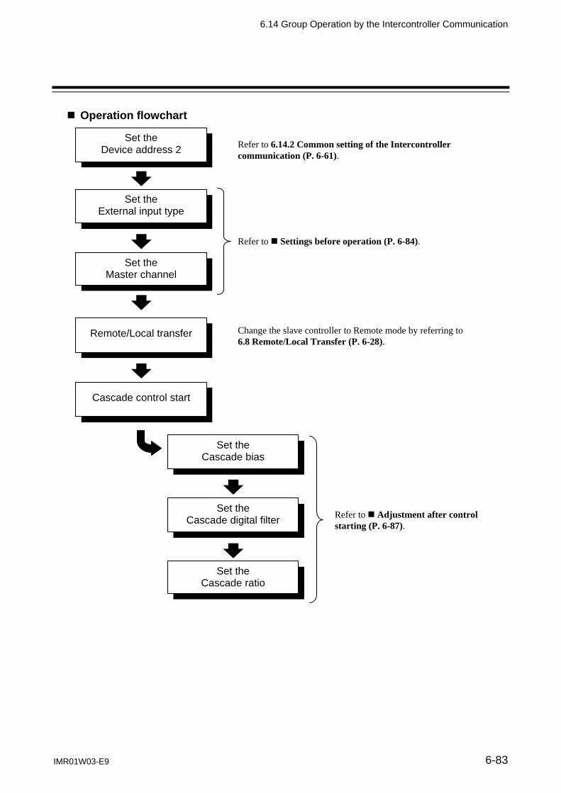
6.14 Group Operation by the Intercontroller Communication
IMR01W03-E9 6-83
Operation flowchart
Set the Device address 2
Set the External input type
Set the Master channel
Set the Cascade bias
Set the Cascade digital filter
Set the Cascade ratio
Remote/Local transfer
Refer to 6.14.2 Common setting of the Intercontroller communication (P. 6-61).
Refer to Settings before operation (P. 6-84).
Refer to Adjustment after control starting (P. 6-87).
Cascade control start
Change the slave controller to Remote mode by referring to 6.8 Remote/Local Transfer (P. 6-28).

6.14 Group Operation by the Intercontroller Communication
IMR01W03-E9 6-84
Settings before operation
When implementing the cascade control, the following items must be set. Device address 2 [Setup setting mode] External input type [Engineering mode: Function block 50] Master channel selection [Engineering mode: Function block 50]
For the Device address 2 setting, refer to 6.14.2 Common setting of the intercontroller communication (P. 6-61).
Set the External input type and Master channel selection Set the External input type for each controller. In addition, select the controller which is to become the Cascade control master.
1. Change the operation mode from RUN mode to STOP mode. To change from RUN mode to STOP mode, refer to 6.4 RUN/STOP Transfer (P. 6-11).
2. Press the Shift key while pressing the SET key for 2 seconds at PV/SV monitor screen until
Engineering mode is displayed. Function block 10 screen is displayed first.
PV/SV monitor Function block 10
(Engineering mode)
Press the Shift key while pressing the SET key for 2 seconds
3. Press the UP key or DOWN key until Function block 50 screen is displayed.
Function block 10 (Engineering mode)
Function block 50 (Engineering mode)

6.14 Group Operation by the Intercontroller Communication
IMR01W03-E9 6-85
4. Press the SET key until External input type setting screen is displayed.
Function block 50 (Engineering mode) External input type
5. Select the External input type which needs to be changed by pressing the UP or DOWN key. Set “0” to the master controller and “1” to the slave controller. Setting range: 0: Remote setting (RS) input
1: Intercontroller communication cascade control 2: Intercontroller communication ratio setting (Factory set value: 0)
External input type
After a new value is displayed on the display by using UP and DOWN keys, if no key operation is performed within 1 minute without pressing SET key, this instrument returns to the PV/SV monitor screen and the External input type will not be changed.
6. Press the SET key to store the new External input type. The screen goes to the Master channel
selection screen.
External input type Master channel selection

6.14 Group Operation by the Intercontroller Communication
IMR01W03-E9 6-86
7. Press the UP key or DOWN key and set the address (value set by the Device address 2 screen) of
the controller specified the cascade control master. Set the Master channel to only the slave controller. No setting of the master controller is required. Setting range: 0 to 31 (Factory set value: 0)
Master channel selection
After a new value is displayed on the display by using UP and DOWN keys, if no key operation is performed within 1 minute without pressing SET key, this instrument returns to the PV/SV monitor screen and the Master channel will not be changed.
8. Press the SET key to store the new Master channel. The screen goes to the next parameter.
Master channel selection SV tracking
9. To return the PV/SV monitor, press the MONI key (for Direct key Type 1), or press the Shift key while pressing the SET key.
10. Set the External input type and Master channel selection of the other controllers by the same
procedures as described in steps 1 to 9 above.
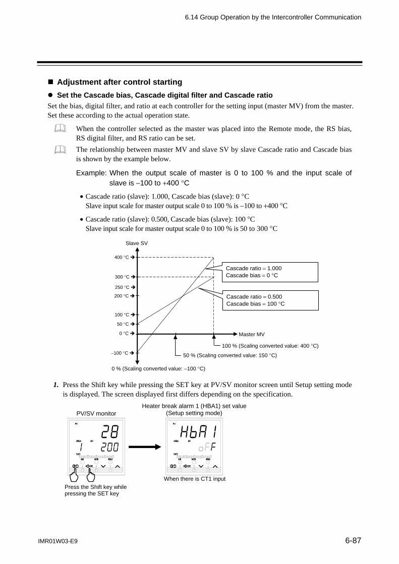
6.14 Group Operation by the Intercontroller Communication
IMR01W03-E9 6-87
Adjustment after control starting
Set the Cascade bias, Cascade digital filter and Cascade ratio
Set the bias, digital filter, and ratio at each controller for the setting input (master MV) from the master. Set these according to the actual operation state.
When the controller selected as the master was placed into the Remote mode, the RS bias, RS digital filter, and RS ratio can be set. The relationship between master MV and slave SV by slave Cascade ratio and Cascade bias is shown by the example below.
Example: When the output scale of master is 0 to 100 % and the input scale of slave is 100 to 400 C
Cascade ratio (slave): 1.000, Cascade bias (slave): 0 C Slave input scale for master output scale 0 to 100 % is 100 to 400 C
Cascade ratio (slave): 0.500, Cascade bias (slave): 100 C Slave input scale for master output scale 0 to 100 % is 50 to 300 C
1. Press the Shift key while pressing the SET key at PV/SV monitor screen until Setup setting mode is displayed. The screen displayed first differs depending on the specification.
PV/SV monitor
Heater break alarm 1 (HBA1) set value(Setup setting mode)
When there is CT1 input
Press the Shift key while pressing the SET key
100 C
0 C
100 C
200 C
300 C
400 C
50 % (Scaling converted value: 150 C)
100 % (Scaling converted value: 400 C)
Master MV
Slave SV
0 % (Scaling converted value: 100 C)
Cascade ratio 1.000 Cascade bias 0 C
Cascade ratio 0.500 Cascade bias 100 C
250 C
50 C

6.14 Group Operation by the Intercontroller Communication
IMR01W03-E9 6-88
2. Press the SET key until Cascade bias screen is displayed.
Press the Shift key, UP key, or DOWN key and set the bias for the setting input (master MV) from the master. Setting range: Input span to Input span (Factory set value: 0)
Cascade bias (RS bias)
If the External input type is Remote setting input, the Cascade bias screen becomes the RS bias screen and if Intercontroller communication ratio setting, it becomes the Ratio setting bias screen. In other places, this is indicated as “RS bias.”
After a new value is displayed on the display by using UP and DOWN keys, if no key operation is performed within 1 minute without pressing SET key, this instrument returns to the PV/SV monitor screen and the Cascade bias will not be changed.
3. Press the SET key to store the new Cascade bias. The screen goes to the Cascade digital filter
screen. Press the Shift key, UP key, or DOWN key and set the digital filter for the setting input (master MV) from the master. Setting range: 0.1 to 100.0 seconds oFF: Unused (Factory set value: oFF)
Cascade digital filter (RS digital filter)
If the External input type is Remote setting input, the Cascade digital filter screen becomes the RS digital filter screen and if Intercontroller communication ratio setting, it becomes the Ratio setting digital filter screen. In other places, this is indicated as “RS digital filter.”
After a new value is displayed on the display by using UP and DOWN keys, if no key operation is performed within 1 minute without pressing SET key, this instrument returns to the PV/SV monitor screen and the Cascade digital filter will not be changed.

6.14 Group Operation by the Intercontroller Communication
IMR01W03-E9 6-89
4. Press the SET key to store the new Cascade digital filter. The screen goes to the Cascade ratio
screen. Press the Shift key, UP key, or DOWN key and set the ratio for the setting input (master MV) from the master. Setting range: 0.001 to 9.999 (Factory set value: 1.000)
Cascade ratio (RS ratio)
If the External input type is Remote setting input, the Cascade ratio screen becomes the RS ratio screen and if Intercontroller communication ratio setting, it becomes the Ratio setting ratio screen. In other places, this is indicated as “RS ratio.”
After a new value is displayed on the display by using UP and DOWN keys, if no key operation is performed within 1 minute without pressing SET key, this instrument returns to the PV/SV monitor screen and the Cascade ratio will not be changed.
5. Press the SET key to store the new Cascade ratio. The screen goes to the next parameter.
Cascade ratio (RS ratio)
Proportional cycle time [heat-side]
6. To return the PV/SV monitor, press the MONI key (for direct key type 1), or press the Shift key while pressing the SET key.
7. Set the Cascade bias, Cascade digital filter and Cascade ratio of the other slaves by the same
procedures as described in steps 1 to 6 above.
For the setting procedure, refer to 5.2.2 Changing and registering of the setting item (P. 5-8) or 6.3 Operating Setting (P. 6-5).

6.14 Group Operation by the Intercontroller Communication
IMR01W03-E9 6-90
Operation procedures
1. Set the Device address 2 for each controller. For the Device address 2 setting, refer to 6.14.2 Common setting of the Intercontroller communication (P. 6-61).
2. Set the External input type for each controller.
Set “0: Remote setting (RS) input” to the master controller, and “1: Intercontroller communication cascade control” to the slave controller.
For the External input type setting, refer to Settings before operation (P. 6-84).
3. Set the master for the Cascade control. Set the address (setting of the Device address 2) of the controller which becomes the master at the controllers which become the slaves. Setting is unnecessary for the master.
For the Master channel setting, refer to Settings before operation (P. 6-84).
4. Change the slave controller to Remote mode. Cascade control by Intercontroller communication can be executed if the slave controllers are in the Remote mode.
Symbol of showing Remote mode
Remote/Local transfer The remote (REM) mode lamp lights.
To change from the Local mode to the Remote mode, refer to 6.8 Remote/Local Transfer (P. 6-28).
5. The settings above starts Cascade control by Intercontroller communication.
6. Perform Cascade bias, Cascade digital filter, and Cascade ratio adjustment which actually
operating. For the Cascade bias, Cascade digital filter, and Cascade ratio, refers to Adjustment after control starting (P. 6-87).

6.14 Group Operation by the Intercontroller Communication
IMR01W03-E9 6-91
6.14.6 Ratio setting function
Ratio setting exercises control with the product of the Set value (SV) from the master multiplied by a fixed ratio as the slave Set value (SV).
Since Intercontroller communication has a time lag (maximum 70 ms number of controllers connected) in data transmission, when using it in a fast response control system, take this time lag into consideration. [The salve Set value (remote SV) is updated at each time lag.]
The Ratio setting by Intercontroller communication can be executed when the Communication 2 port (COM2) is usable. In addition, Ratio setting slave controllers cannot use Remote setting input.
The maximum number of combined master and slave controllers connectable at Intercontroller communication is 32.
Example: When using 3 controllers and setting extruders in ratio
Specify one controller as the master and use the remaining two controllers as slaves. The product of the master Set value (SV) multiplied by a fixed ratio becomes the slave Set value (SV).
Connection status of the Intercontroller communication
Controller No. 1 (Master)
Controller No. 2 (Slave)
Controller No. 3 (Slave)
Intercontroller communication Intercontroller communication
MVPV
Communication
Control system A Control system B Control system C
Communication 2
Local SV PID
Remote SV
PV
Master SV
Local SV PID
MV
Digitalfilter
Ratio
Bias
Remote SV
Communication 2
PV
Master SV
Local SV PID
MV
Digital filter
Ratio
Bias
Remote SV
Communication 2
Communication Communication
Block diagram of Ratio setting by Intercontroller communication
Controller No. 1
(Master)
Controller No. 2
(Slave)
Controller No. 3
(Slave)

6.14 Group Operation by the Intercontroller Communication
IMR01W03-E9 6-92
Operation flowchart
Set the Device address 2
Set the External input type
Set the Master channel
Set the Ratio setting bias
Set the Ratio setting digital filter
Set the Ratio setting ratio
Remote/Local transfer
Refer to 6.14.2 Common setting of the Intercontroller communication (P. 6-61).
Refer to Settings before operation (P. 6-93).
Refer to Adjustment after control starting (P. 6-96).
Ratio setting start
Change the slave controller to Remote mode by referring to 6.8 Remote/Local Transfer (P. 6-28).
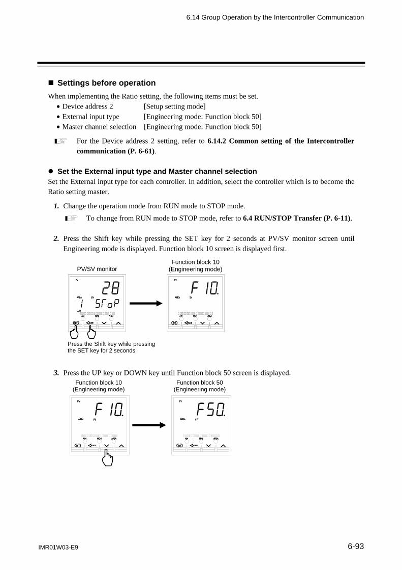
6.14 Group Operation by the Intercontroller Communication
IMR01W03-E9 6-93
Settings before operation
When implementing the Ratio setting, the following items must be set. Device address 2 [Setup setting mode] External input type [Engineering mode: Function block 50] Master channel selection [Engineering mode: Function block 50]
For the Device address 2 setting, refer to 6.14.2 Common setting of the Intercontroller communication (P. 6-61).
Set the External input type and Master channel selection Set the External input type for each controller. In addition, select the controller which is to become the Ratio setting master.
1. Change the operation mode from RUN mode to STOP mode. To change from RUN mode to STOP mode, refer to 6.4 RUN/STOP Transfer (P. 6-11).
2. Press the Shift key while pressing the SET key for 2 seconds at PV/SV monitor screen until
Engineering mode is displayed. Function block 10 screen is displayed first.
PV/SV monitor Function block 10
(Engineering mode)
Press the Shift key while pressingthe SET key for 2 seconds
3. Press the UP key or DOWN key until Function block 50 screen is displayed.
Function block 10 (Engineering mode)
Function block 50 (Engineering mode)

6.14 Group Operation by the Intercontroller Communication
IMR01W03-E9 6-94
4. Press the SET key until External input type setting screen is displayed.
Function block 50 (Engineering mode) External input type
5. Select the External input type which needs to be changed by pressing the UP or DOWN key. Set “0” to the master controller and “2” to the slave controller. Setting range: 0: Remote setting (RS) input
1: Intercontroller communication cascade control 2: Intercontroller communication ratio setting (Factory set value: 0)
External input type
After a new value is displayed on the display by using UP and DOWN keys, if no key operation is performed within 1 minute without pressing SET key, this instrument returns to the PV/SV monitor screen and the External input type will not be changed.
6. Press the SET key to store the new External input type. The screen goes to Master channel
selection screen.
External input type Master channel selection

6.14 Group Operation by the Intercontroller Communication
IMR01W03-E9 6-95
7. Press the UP key or DOWN key and set the address (value set by the Device address 2 screen) of
the controller specified the ratio setting master. Set the Master channel to only the slave controller. No setting of the master controller is required. Setting range: 0 to 31 (Factory set value: 0)
Master channel selection
After a new value is displayed on the display by using UP and DOWN keys, if no key operation is performed within 1 minute without pressing SET key, this instrument returns to the PV/SV monitor screen and the Master channel will not be changed.
8. Press the SET key to store the new Master channel. The screen goes to the next parameter.
Master channel selection SV tracking
9. To return the PV/SV monitor, press the MONI key (for Direct key Type 1), or press the Shift key while pressing the SET key.
10. Set the External input type and Master channel selection of the other controllers by the same
procedures as described in steps 1 to 9 above.
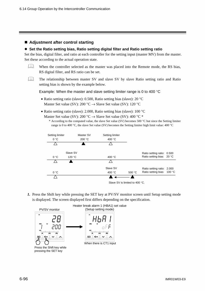
6.14 Group Operation by the Intercontroller Communication
6-96 IMR01W03-E9
Adjustment after control starting
Set the Ratio setting bias, Ratio setting digital filter and Ratio setting ratio Set the bias, digital filter, and ratio at each controller for the setting input (master MV) from the master. Set these according to the actual operation state.
When the controller selected as the master was placed into the Remote mode, the RS bias, RS digital filter, and RS ratio can be set.
The relationship between master SV and slave SV by slave Ratio setting ratio and Ratio setting bias is shown by the example below.
Example: When the master and slave setting limiter range is 0 to 400 C
Ratio setting ratio (slave): 0.500, Ratio setting bias (slave): 20 C Master Set value (SV): 200 C Slave Set value (SV): 120 C
Ratio setting ratio (slave): 2.000, Ratio setting bias (slave): 100 C Master Set value (SV): 200 C Slave Set value (SV): 400 C *
* According to the computed value, the slave Set value (SV) becomes 500 C but since the Setting limiter range is 0 to 400 C, the slave Set value (SV) becomes the Setting limiter high limit value: 400 C
1. Press the Shift key while pressing the SET key at PV/SV monitor screen until Setup setting mode is displayed. The screen displayed first differs depending on the specification.
PV/SV monitor
Heater break alarm 1 (HBA1) set value(Setup setting mode)
When there is CT1 input
Press the Shift key while pressing the SET key
0 C 200 C 400 CMaster SV
0 C 120 C 400 CSlave SV Ratio setting ratio: 0.500
Ratio setting bias: 20 C
0 C 500 C400 CSlave SV Ratio setting ratio: 2.000
Ratio setting bias: 100 C
Setting limiterSetting limiter
Slave SV is limited to 400 C.

6.14 Group Operation by the Intercontroller Communication
IMR01W03-E9 6-97
2. Press the SET key until Ratio setting bias screen is displayed.
Press the Shift key, UP key, or DOWN key and set the bias for the setting input (master SV) from the master. Setting range: Input span to Input span (Factory set value: 0)
Ratio setting bias (RS bias)
If the External input type is Remote setting input, the Ratio setting bias screen becomes the RS bias screen and if Intercontroller communication cascade control, it becomes the Cascade bias screen. In other places, this is indicated as “RS bias.”
After a new value is displayed on the display by using UP and DOWN keys, if no key operation is performed within 1 minute without pressing SET key, this instrument returns to the PV/SV monitor screen and the Ratio setting bias will not be changed.
3. Press the SET key to store the new Ratio setting bias. The screen goes to Ratio setting digital
filter screen. Press the Shift key, UP key, or DOWN key and set the digital filter for the setting input (master SV) from the master. Setting range: 0.1 to 100.0 seconds oFF: Unused (Factory set value: oFF)
Ratio setting digital filter (RS digital filter)
If the External input type is Remote setting input, the Ratio setting digital filter screen becomes the RS digital filter screen and if Intercontroller communication cascade control, it becomes the Cascade digital filter screen. In other places, this is indicated as “RS digital filter.”
After a new value is displayed on the display by using UP and DOWN keys, if no key operation is performed within 1 minute without pressing SET key, this instrument returns to the PV/SV monitor screen and the Ratio setting digital filter will not be changed.

6.14 Group Operation by the Intercontroller Communication
IMR01W03-E9 6-98
4. Press the SET key to store the new Ratio setting digital filter. The screen goes to Ratio setting
ratio screen. Press the Shift key, UP key, or DOWN key and set the ratio for the setting input (master SV) from the master. Setting range: 0.001 to 9.999 (Factory set value: 1.000)
Ratio setting ratio (RS ratio)
If the External input type is Remote setting input, the Ratio setting ratio screen becomes the RS ratio screen and if Intercontroller communication cascade control, it becomes the Cascade ratio screen. In other places, this is indicated as “RS ratio.”
After a new value is displayed on the display by using UP and DOWN keys, if no key operation is performed within 1 minute without pressing SET key, this instrument returns to the PV/SV monitor screen and the Ratio setting ratio will not be changed.
5. Press the SET key to store the new Ratio setting ratio. The screen goes to the next parameter.
Ratio setting ratio(RS ratio)
Proportional cycle time [heat-side]
6. To return the PV/SV monitor, press the MONI key (for Direct key Type 1), or press the Shift key while pressing the SET key.
7. Set the Ratio setting bias, Ratio setting digital filter and Ratio setting ratio of the other slaves by
the same procedures as described in steps 1 to 6 above.
For the setting procedure, refer to 5.2.2 Changing set value (SV) (P. 5-8) or 6.3 Operating Setting (P. 6-5).

6.14 Group Operation by the Intercontroller Communication
IMR01W03-E9 6-99
Operation procedures
1. Set the Device address 2 for each controller. For the Device address 2 setting, refer to 6.14.2 Common setting of the Intercontroller communication (P. 6-61).
2. Set the External input type for each controller.
Set “0: Remote setting (RS) input” to the master controller, and “2: Intercontroller communication ratio setting” to the slave controller.
For the External input type setting, refer to Settings before operation (P. 6-93).
3. Set the master for the ratio setting. Set the address (setting of the Device address 2) of the controller which becomes the master at the controllers which become the slaves. Setting is unnecessary for the master.
For the Master channel setting, refer to Settings before operation (P. 6-93).
4. Change the slave controller to Remote mode. Ratio setting by Intercontroller communication can be executed if the slave controllers are in the Remote mode.
Symbol of showing Remote mode
Remote/Local transfer The remote (REM) mode lamp lights.
To change from the Local mode to the Remote mode, refer to 6.8 Remote/Local Transfer (P. 6-28).
5. The settings above starts ratio setting by Intercontroller communication.
6. Perform Ratio setting bias, Ratio setting digital filter, and Ratio setting ratio adjustment which
actually operating. For the Ratio setting bias, Ratio setting digital filter, and Ratio setting ratio, refer to Adjustment after control starting (P. 6-96).

6.14 Group Operation by the Intercontroller Communication
IMR01W03-E9 6-100
Usage example
Example 1 Depending on the master channel setting, the following Master/Slave relationship can be established.
Controller No. Device address 2 Set the
Master channel Master/Slave
1 0 Master
2 1 0 Slave
3 2 0 Slave/Master *
4 3 0 Slave
5 4 2 Slave
6 5 2 Slave
* Controller No. 3 becomes a controller number 1 slave and the master of controller No. 5 and No. 6.
Controller No. 1
Address: 0 Master
Controller No. 2
Address: 1 Master setting: 0
Slave
Controller No. 3
Address: 2 Master setting: 0
Slave/Master
Controller No. 4
Address: 3 Master setting: 0
Slave
Controller No. 5
Address: 4 Master setting: 2
Slave
Controller No. 6
Address: 5 Master setting: 2
Slave
Master/Slave relationship 1
Master/Slave relationship 2

6.14 Group Operation by the Intercontroller Communication
IMR01W03-E9 6-101
Example 2 When ratio setting by Intercontroller communication by a connection like that shown below was performed, a difference in the master SV change and slave SV change is generated. Input the program controller Set value (SV) to the ratio setting master by Intercontroller communication as Remote setting input. The master SV values continuously change gradually, the same as the program controller Set value (SV), but since there is a time lag due to Intercontroller communication, the slave SV changes in a stepped state.
Program Controller
FB400/900 FB400/900 FB400/900
SV
Remote setting input
Intercontroller communication
Master Slave Slave
Temperature
Time
Time lag (Maximum 70 ms number of controllers connected)
Slave SV
Master SV
Master SV change and Slave SV change

IMR01W03-E9 6-102
MEMO
PARAMETERDESCRIPTION
IMR01W03-E9 7-1
7.1 SV Setting & Monitor Mode .............................................................. 7-2 7.1.1 Display sequence (When the Direct key type is Type 1) ...................... 7-2 7.1.2 Display sequence (When the Direct key type is Type 2) ...................... 7-3 7.1.3 Monitor and setting item ....................................................................... 7-4
7.2 Operation Mode .............................................................................. 7-14 7.2.1 Display sequence ............................................................................... 7-14 7.2.2 Operation item .................................................................................... 7-15
7.3 Parameter Setting Mode ................................................................. 7-19 7.3.1 Display sequence ............................................................................... 7-20 7.3.2 Parameter setting item ....................................................................... 7-21
7.4 Setup Setting Mode ........................................................................ 7-34 7.4.1 Display sequence ............................................................................... 7-34 7.4.2 Setup setting item .............................................................................. 7-35
7.5 Engineering Mode ........................................................................... 7-48 7.5.1 Display Sequence .............................................................................. 7-48 7.5.2 Precaution against parameter change ............................................... 7-55 7.5.3 Engineering setting item ..................................................................... 7-62

7. PARAMETER DESCRIPTION
7-2 IMR01W03-E9
7.1 SV Setting & Monitor Mode
In SV setting & monitor mode, the following operations are possible. Change the Set value (SV) Change memory area Monitor the Measured value (PV) and the Manipulated output value (MV), etc.
The display sequence of SV setting & monitor mode display differs depending on the Direct key type. There are two types of direct key: Type 1 and Type2. They can be selected in Engineering mode. 7.1.1 Display sequence (When the Direct key type is Type 1)
Measured value (PV)/ Set value (SV) monitor
MONIkey
Memory area transfer
SET key
MONI key
MONI key
AREA key
SET key
MONIkey
Current transformer 1 (CT1) input value monitor
Remote setting (RS) input value monitor
Set value (SV)
MONIkey
MONI key
Manipulated output value (MV1) monitor [heat-side]
Manipulated output value (MV2) monitor [cool-side]
Event monitor 1
MONIkey
SETkey
Manipulated output valueat MV transfer
Interlock release
Memory area soak time monitor
Event monitor 2
NONI key
SETkey
Current transformer 2 (CT2) input value monitor
MONIkey
SET key
(P.7-7) (P.7-7) (P.7-7) (P.7-8)
(P.7-5)
(P.7-10) (P.7-10) (P.7-9) (P.7-8)
(P.7-7) (P.7-11) (P.7-13)
(P.7-11)
Some parameters may not be displayed when the relevant function is not set so as to be activated or no relevant specification is selected when ordering.

7.1 SV Setting & Monitor Mode
IMR01W03-E9 7-3
7.1.2 Display sequence (When the Direct key type is Type 2)
SETkey
SETkey
SET key
SETkey
Measured value (PV)/ Set value (SV) monitor
Current transformer 1 (CT1) input value monitor
Current transformer 2 (CT2) input value monitor
Remote setting (RS) input value monitor
Event monitor 1
Set value (SV)
Interlock release
SETkey
SETkey
Event monitor 2
Memory area soak time monitor
Manipulated output value (MV1) monitor [heat-side]
Manipulated output value (MV2) monitor [cool-side]
Manipulated output valueat MV transfer
Memory area transfer
SETkey
SETkey
SET key
SET key
SETkey
SETkey
SETkey
(P.7-7) (P.7-7) (P.7-7) (P.7-7)
(P.7-5)
(P.7-10) (P.7-9) (P.7-8) (P.7-8)
(P.7-13) (P.7-11) (P.7-11) (P.7-10)
Some parameters may not be displayed when the relevant function is not set so as to be activated or no relevant specification is selected when ordering.

7.1 SV Setting & Monitor Mode
IMR01W03-E9 7-4
7.1.3 Monitor and setting item
Pictogram description
Pictogram Name Description
MEMORY
AREA
Memory area function
Parameters which can be stored in the memory area
DATA LOCK
Data lock function
Parameters which can be locked so that no data can be changed.
CT input
OPTION
Current transformer (CT)
input
Parameters relating to any relevant optional for the FB400/900 having those optional.
FBR input
OPTION
Feedback resistance (FBR)
input
Commu- nication
OPTION
Communication function
(Communication1 or
Communication 2)
PFF input
OPTION
Power feed forward (PFF)
input
AO
OPTION
Transmission output
Digital output
OPTION
Digital output (DO)

7.1 SV Setting & Monitor Mode
IMR01W03-E9 7-5
Measured value (PV)/Set value (SV) monitor FBR
input
OPTION
Measured value (PV) display (hereinafter called the PV display): Measured value (PV) is displayed.
Set value (SV) display (hereinafter called the SV display): The target value for control is displayed. The value to be displayed varies depending on the state of operation mode. Set value (SV)* is displayed when the operation mode is Local mode. Remote setting input value (RS)* is displayed when operation mode is
Remote mode. On each controller on the slave side while in Intercontroller communication: For Intercontroller communication ratio setting or Intercontroller communication cascade control, set the controller on the slave side to the remote mode. In this case, the displayed value is that obtained by adding digital filter, bias or ratio to the value from the controller on the master side.
Manual manipulated output value is displayed when the operation mode is Manual mode. In addition, the Manipulated output value (MV) can be manually set. (Refer to P. 6-27) - In the PID control, displays the Manipulated output value (MV1) [heat-side]. - In the Heat/Cool PID control, displays the Manipulated output value (MV1)
[heat-side] or Manipulated output value (MV2) [cool-side]. - When the control action is the Position proportioning PID control:
When the Feedback resistance (FBR) input is provided, Manipulated output value (MV) is displayed. In addition, when the Feedback resistance (FBR) input is not provided, nothing will appear in the SV display.
* With the Setting change rate limiter when the set value is changed, the displayed set value changes according to the ramp-up/down rate.
Display or data range Factory
set value
Measured value (PV): Input scale low to Input scale high Varies with the setting of the Decimal point position (P. 7-71).
Set value (SV) or Remote setting (RS) input value: Setting limiter low to Setting limiter high Varies with the setting of the Decimal point position (P. 7-71).
Manipulated output value (MV1 or MV2): PID control: Output limiter low (MV1) to Output limiter high (MV1) (5.0 to +105.0 %) Heat/Cool PID control: Output limiter high (MV2) to +Output limiter high (MV1) (105.0 to +105.0 %)
In the STOP mode, displays the “SToP” character on the PV or SV display. Display position of “SToP” can be set in the Engineering mode (P. 7-62).
When Heat/Cool PID control is performed, it is necessary to select Output 2 (OUT2) when ordering.
SV monitor
PV monitor

7.1 SV Setting & Monitor Mode
IMR01W03-E9 7-6
Display processing of Measured value (PV) monitor
The value obtained after a captured input value is processed as shown in the following corresponds to the Measured value (PV) which will be displayed on the PV monitor.
Input value
PV digital filter
PV ratio
PV bias
Square rootextraction
PV low inputcut-off
Measured value (PV)
Input scale high/low
PV monitor
Display processing of Set value (SV) monitor
The value obtained after Remote setting (RS) input, Memory area set value (SV) or Local set value (SV) is processed as shown in the following corresponds to the Set value (SV) which will be displayed on the SV monitor.
Remote setting (RS) input
RS digital filter
RS ratio
RS bias
PV low input cut-off
Set value (SV)
Remoter setting (RS) input value
SV monitor
Manipulated output value (MV) from master controller (Intercontroller communication cascade control)
Set value (SV) from master controller (Intercontroller communication ratio setting)
Memory area Set value (SV)
Local set value (SV)
Automatic temperature rise dead time
Automatic temperature rise gradient data
Setting change rate limiter
Memory areaSetting change
rate limiter
Manipulated output vale
(MV1 or MV2)
Remote/Local transfer
Auto/Manual transfer
Transfer of remote setting input, cascade control or ratio setting
Transfer of Remote setting input or Cascade control
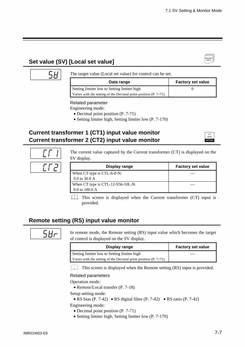
7.1 SV Setting & Monitor Mode
IMR01W03-E9 7-7
Set value (SV) [Local set value]
MEMORY AREA
The target value (Local set value) for control can be set.
Data range Factory set value
Setting limiter low to Setting limiter high Varies with the setting of the Decimal point position (P. 7-71).
0
Related parameter Engineering mode: Decimal point position (P. 7-71) Setting limiter high, Setting limiter low (P. 7-170)
Current transformer 1 (CT1) input value monitor Current transformer 2 (CT2) input value monitor
CT input
OPTION
The current value captured by the Current transformer (CT) is displayed on the SV display.
Display range Factory set value
When CT type is CTL-6-P-N: 0.0 to 30.0 A
When CT type is CTL-12-S56-10L-N: 0.0 to 100.0 A
This screen is displayed when the Current transformer (CT) input is provided.
Remote setting (RS) input value monitor
In remote mode, the Remote setting (RS) input value which becomes the target of control is displayed on the SV display.
Display range Factory set value
Setting limiter low to Setting limiter high Varies with the setting of the Decimal point position (P. 7-71).
This screen is displayed when the Remote setting (RS) input is provided.
Related parameters Operation mode: Remote/Local transfer (P. 7-18)
Setup setting mode: RS bias (P. 7-42) RS digital filter (P. 7-42) RS ratio (P. 7-42)
Engineering mode: Decimal point position (P. 7-71) Setting limiter high, Setting limiter low (P. 7-170)

7.1 SV Setting & Monitor Mode
IMR01W03-E9 7-8
Event monitor 1
In case of event occurrence, “o” is lit in the digit of the SV display. It is possible to check the type of created event depending on which digit was lit.
Event 1 (EV1) Event 2 (EV2) Event 3 (EV3) Event 4 (EV4)
This screen is displayed when event action is selected for any from Event 1 type to Event 4 type.
Related parameters Engineering mode: Event 1 type (P. 7-85) Event 3 type (P. 7-102) Event 2 type (P. 7-95) Event 4 type (P. 7-109)
Event monitor 2 CT
input
OPTION
In case of Heater break alarm (HBA) occurrence, “o” is lit in the digit of the SV display. It is possible to check the type of Heater break alarm (HBA) which occurred depending on which digit was lit.
Heater break alarm 1 (HBA1)Heater break alarm 2 (HBA2)
This screen is not displayed when set the CT assignment to “0: None.”
Related parameters Engineering mode: CT1 assignment (P. 7-117) CT2 assignment (P. 7-121)
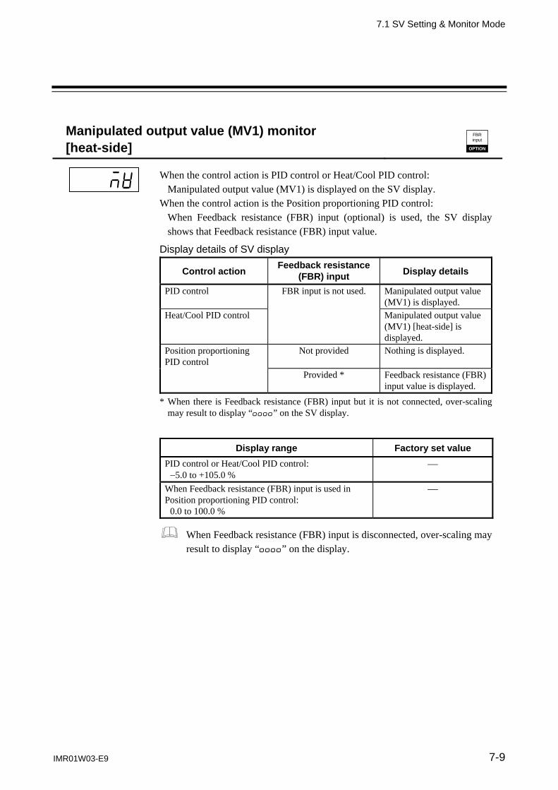
7.1 SV Setting & Monitor Mode
IMR01W03-E9 7-9
Manipulated output value (MV1) monitor [heat-side]
FBR input
OPTION
When the control action is PID control or Heat/Cool PID control: Manipulated output value (MV1) is displayed on the SV display.
When the control action is the Position proportioning PID control: When Feedback resistance (FBR) input (optional) is used, the SV display shows that Feedback resistance (FBR) input value.
Display details of SV display
Control action Feedback resistance
(FBR) input Display details
PID control FBR input is not used. Manipulated output value (MV1) is displayed.
Heat/Cool PID control Manipulated output value (MV1) [heat-side] is displayed.
Position proportioning PID control
Not provided Nothing is displayed.
Provided * Feedback resistance (FBR) input value is displayed.
* When there is Feedback resistance (FBR) input but it is not connected, over-scaling may result to display “oooo” on the SV display.
Display range Factory set value
PID control or Heat/Cool PID control: 5.0 to +105.0 %
When Feedback resistance (FBR) input is used in Position proportioning PID control: 0.0 to 100.0 %
When Feedback resistance (FBR) input is disconnected, over-scaling may result to display “oooo” on the display.

7.1 SV Setting & Monitor Mode
IMR01W03-E9 7-10
Manipulated output value (MV2) monitor [cool-side]
Manipulated output value (MV2) of cool-side is displayed.
Display range Factory set value
5.0 to +105.0 %
This screen is displayed when in Heat/Cool PID control. Related parameter Engineering mode: Control action (P. 7-129)
Memory area soak time monitor
Monitors the time elapsed for memory area operation (soak time) when Ramp/Soak control by using Multi-memory area is performed.
Display example:
Memory area
soak time is
displayed. Memory area 2
Memory area 1
Memory area 3
Memory area 4
Memory area 5
Time
Measured value (PV)
Area soak time
Setting change rate limiter
Link area number
Display range Factory set value
0 minutes 00 seconds to 199 minutes 59 seconds or 0 hours 00 minutes to 99 hours 59 minutes
Related parameters Parameter setting mode: Area soak time (P. 7-32) Link area number (P. 7-33)
Engineering mode: Soak time unit (P. 7-169)

7.1 SV Setting & Monitor Mode
IMR01W03-E9 7-11
Memory area transfer
Selects the memory area (Control area) used for control.
Data range Factory set value
1 to 8 1
When the Direct key type is Type 1, pressing the AREA key can be changed to the memory area transfer screen. Memory area transfer screen is displayed in SV setting & Monitor mode when the Direct key type is Type 2.
Related parameter Engineering mode: Direct key type (P. 7-68)
Manipulated output value at MV transfer
This is the final Manipulated output value used under Manual control when the control mode is transferred to Auto control from Manual control.
Data range Factory set value
PID control: Output limiter low (MV1) to Output limiter high (MV1) (5.0 to +105.0 %)
0.0
Heat/Cool PID control: Output limiter high (MV2) to +Output limiter high (MV1) For overlap: 105.0 to +105.0 % * * Actual output value is limited by the output limiter function.
0.0
This screen is not displayed when the MV transfer function is set to “0.”
Related parameter Engineering mode: MV transfer function (P. 7-128)
Continued on the next page.

7.1 SV Setting & Monitor Mode
IMR01W03-E9 7-12
Continued from the previous page. Description of function
This is the final Manipulated output value used under Manual control when the control mode is transferred to Auto mode from Manual mode. This final Manipulated output value is stored and that displays on the Manipulated output value at MV transfer screen. This final Manipulated output value is used as a Manipulated output value in Manual control when control mode is transferred to Manual mode next time. (MV transfer function) Example 1:
Manual mode
The final Manipulated output value is stored.
Control mode is transferred to
Auto mode from Manual mode.
The final Manipulated output value (40.6 %) is transmitted when control mode istransferred to Manual mode next time. (MV transfer function)
Auto mode Manual mode
Control mode is transferred to
Manual mode from Auto mode.
The final Manipulated output value
Manipulated output value at MV transfer screen
In addition, on this screen it is possible to manually change Manipulated output values (MV1 and MV2) in Auto mode. However, it they are changed in Auto mode, these manipulated output values thus changed are transferred when selected to the Manual mode next time. Example 2:
Manual mode
The final Manipulated output value is stored.
Control mode is transferred to
Auto mode from Manual mode. Auto mode Manual
mode
Control mode is transferred to
Manual mode from Auto mode.
The manipulated output value is
manually changed in Auto mode.
The new Manipulated output value (30.0 %) istransmitted when control mode is transferredto Manual mode next time.
The final Manipulated output value
The new Manipulatedoutput value
Manipulated output value can be changed by the UP, DOWN or shift keys.
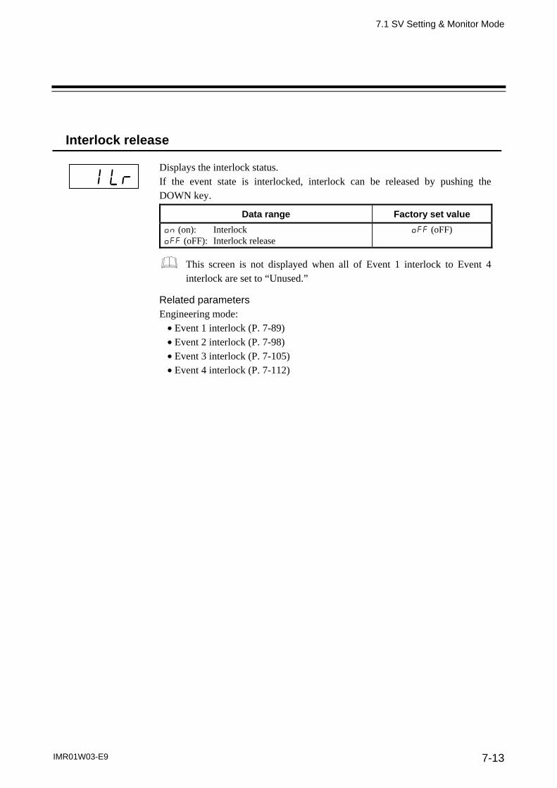
7.1 SV Setting & Monitor Mode
IMR01W03-E9 7-13
Interlock release
Displays the interlock status. If the event state is interlocked, interlock can be released by pushing the DOWN key.
Data range Factory set value
on (on): Interlock oFF (oFF): Interlock release
oFF (oFF)
This screen is not displayed when all of Event 1 interlock to Event 4 interlock are set to “Unused.”
Related parameters Engineering mode: Event 1 interlock (P. 7-89) Event 2 interlock (P. 7-98) Event 3 interlock (P. 7-105) Event 4 interlock (P. 7-112)

7. PARAMETER DESCRIPTION
7-14 IMR01W03-E9
7.2 Operation Mode
The Operation mode is used to selects the operation modes (PID/AT, Auto/Manual, Remote/Local or RUN/STOP) of the instrument. In addition, the Startup tuning (ST) and Automatic temperature rise learning function can be set. 7.2.1 Display sequence
Press and hold
the shift key for 2 seconds
Shift key
Shift key
Shift key
Measured value (PV)/ Set value (SV) monitor
Auto/Manual transter (A-M)
Shift key
Startup tuning (ST)(STU)
Automatic temperature rise learning (CHr)
PID/AT transfer (ATU)
UP keyDOWN key UP key
DOWNkey
UP keyDOWNkey
UP keyDOWNkey
UP keyDOWN key
Remote/Local transfer (r-L)
UP keyDOWN key
RUN/STOP transfer (r-S)
UP keyDOWNkey
Shift key
Shift key
(P.7-15)
(P.7-16)
(P.7-17) (P.7-17)
(P.7-5)
(P.7-18) (P.7-18)
The SET key as well as the shift key enables the transfer of operation items.
Some parameters may not be displayed when the relevant function is not set so as to be activated or no relevant specification is selected when ordering.
Display returns to the SV setting & monitor mode if no key operation is performed within 1 minute.

7.2 Operation Mode
IMR01W03-E9 7-15
7.2.2 Operation item
PID/AT transfer
Activation or deactivation of the Autotuning (AT) function is selected.
Data range Factory set value
on (on): Autotuning (AT) oFF (oFF): PID control
oFF (oFF)
For the activating method and condition of the Autotuning (AT) function, refer to 6.5 Autotuning (AT) (P. 6-15).
Related parameters Engineering mode: AT bias (P. 7-146) AT cycles (P. 7-147) AT differential gap time (P. 7-148) Output value with AT turned on, Output value with AT turned off (P. 7-149) Proportional band limiter (high) [heat-side],
Proportional band limiter (low) [heat-side] (P. 7-150) Integral time limiter (high) [heat-side],
Integral time limiter (low) [heat-side] (P. 7-151) Derivative time limiter (high) [heat-side],
Derivative time limiter (low) [heat-side] (P. 7-152) Proportional band limiter (high) [cool-side],
Proportional band limiter (low) [cool-side] (P. 7-153) Integral time limiter (high) [cool-side],
Integral time limiter (low) [cool-side] (P. 7-154) Derivative time limiter (high) [cool-side],
Derivative time limiter (low) [cool-side] (P. 7-155) Proportional band adjusting factor [heat-side],
Proportional band adjusting factor [cool-side] (P. 7-156) Integral time adjusting factor [heat-side],
Integral time adjusting factor [cool-side] (P. 7-156) Derivative time adjusting factor [heat-side],
Derivative time adjusting factor [cool-side] (P. 7-157)

7.2 Operation Mode
IMR01W03-E9 7-16
Startup tuning (ST)
Use to set the number of execution times of Startup tuning (ST).
Data range Factory set value
On1 (on1): Execute once On2 (on2): Execute always oFF (oFF): ST unused
oFF (oFF)
This screen is displayed when in Position proportioning PID control.
When in Heat/Cool PID control, it is possible to execute the Startup tuning (ST) function only in the temperature rise direction. The PID values on the heat side are automatically computed.
If the optimum PID constants cannot be obtained by the Startup tuning (ST), please execute the Autotuning (AT).
For details of the Startup tuning (ST), refer to 6.6 Startup Tuning (ST) (P. 6-18).
Related parameters Engineering mode: ST proportional band adjusting factor (P. 7-163) ST integral time adjusting factor (P. 7-164) ST derivative time adjusting factor (P. 7-164) ST start condition (P. 7-163)
Description of function
The Startup tuning (ST) function is used to automatically compute PID constants from the temperature rise characteristic (gradient: arrival time to SV) when power is turned on or the Set value (SV) is changed. If the Startup tuning (ST) function is used for any equipment which requires a long period of time for executing the Autotuning (AT) function, no time of executing the Autotuning (AT) function becomes necessary. Timing of activating the Startup tuning (ST) can be selected from among the following three types. - Activate the Startup tuning (ST) function when the power is turned on; when transferred from STOP to RUN; or
when the Set value (SV) is changed.
- Activate the Startup tuning (ST) function when the power is turned on; or when transferred from STOP to RUN.
- Activate the Startup tuning (ST) function when the Set value (SV) is changed.
Power is turned on or control is changed to RUN from STOP.
Set value (SV)
Startup tuning (ST) is turned on.
Activate the Startup tuning (ST) function when the power is turned on; or when transferred from STOP to RUN.
Set value (SV) is changed.
Set value (SV)
Startup tuning (ST) is turned on.
Activate the Startup tuning (ST) function when the Set value (SV) is changed.
Set value (SV) is changed.
Set value (SV)
Startup tuning (ST) is turned on.
Activate the Startup tuning (ST) function when the power is turned on; when transferred from STOP to RUN; or when the Set value (SV) is changed.
Set value (SV) after being changed
Power is turned on or control is changed to RUN from STOP.
Set value (SV) after being changed

7.2 Operation Mode
IMR01W03-E9 7-17
Automatic temperature rise learning
Use to select Use/Unuse of the Automatic temperature rise learning function.
Data range Factory set value
on (on): Learning oFF (oFF): Unused
on (on)
This screen is not displayed when set the Automatic temperature rise group to “0.”
When in Heat/Cool PID control, an Automatic temperature rise only in the temperature rise direction is enabled.
For details of the Automatic temperature rise learning function, refer to 6.14.4 Automatic temperature rise function (with learning function) (P. 6-72).
Related parameters Engineering mode: Automatic temperature rise group (P. 7-165) Automatic temperature rise dead time (P. 7-167) Automatic temperature rise gradient data (P. 7-167)
Description of function
This is the function to find Automatic temperature rise dead time and Automatic temperature rise gradient data necessary for an Automatic temperature rise. Learning starts if set to “on: Learning” and changed to control RUN to STOP. After Automatic temperature rise dead time and Automatic temperature rise gradient data are found, the learning function is deactivated.
Auto/Manual transfer
Use to transfer the Auto mode or Manual mode. Auto mode: Automatic control is performed. Manual mode: The Manipulated output value (MV1 or MV2) can be
manually changed. The Manipulated output value can be changed on the Measured value (PV)/Set value (SV) monitor.
Data range Factory set value
AUTo (AUTo): Auto mode MAn (MAn): Manual mode
AUTo (AUTo)
Even when in Auto mode, it is possible to manually change the manipulated output value on the Manipulated output value at MV transfer screen.
For details of the Auto/Manual transfer, refer to 6.7 Auto/Manual transfer (P. 6-23).

7.2 Operation Mode
IMR01W03-E9 7-18
Remote/Local transfer
Use to transfer the Remote mode or Local mode. Local mode: Control is performed at the Local set value (SV). Remote mode: Control is performed with a Remote setting (RS) input value.
Data range Factory set value
LoC (LoC): Local mode rEM (rEM): Remote mode
LoC (LoC)
For Intercontroller communication ratio setting or Intercontroller communication cascade control, set the controller on the slave side to the Remote mode.
For details of the Remote/Local transfer, refer to 6.8 Remote/Local Transfer (P. 6-28).
For details of the Intercontroller communication function, refer to 6.14 Group Operation by the Intercontroller Communication (P. 6-60).
Related parameters Engineering mode: External input type (P. 7-125) SV tracking (P. 7-127)
RUN/STOP transfer
Use to transfer the RUN (control RUN) or STOP (control STOP).
Data range Factory set value
rUn (rUn): RUN (Control RUN) SToP (SToP): STOP (Control STOP)
rUn (rUn)
For details of the RUN/STOP transfer, refer to 6.4 RUN/STOP Transfer (P. 6-11).
If the Group RUN/STOP function is used, refer to 6.14.3 Group RUN/STOP function (P. 6-63).

7. PARAMETER DESCRIPTION
IMR01W03-E9 7-19
7.3 Parameter Setting Mode
Parameters of Parameter setting mode can be stored in the memory area. Multi-memory area function
Multi-memory area function can store up to 8 individual sets of SVs and parameters in Parameter setting mode. One of the Areas is used for control, and the currently selected area is Control area. If the set values are stored in divided memory areas for each work process, it is possible to collectively call up all of these set values necessary for the process simply by changing the corresponding memory area numbers.
Working process 1 Working process 2 Working process 8
To control area
Memory area 1
Set value (SV) Event 1 set value (EV1) Event 2 set value (EV2) Event 3 set value (EV3) Event 4 set value (EV4) Control loop break alarm (LBA) time LBA deadband Proportional band [heat-side] Integral time [heat-side] Derivative time [heat-side] Control response parameter Proportional band [cool-side] Integral time [cool-side] Derivative time [cool-side] Overlap/Deadband Manual reset Setting change rate limiter (up) Setting change rate limiter (down) Area soak time Link area number
Memory area 2
Set value (SV) Event 1 set value (EV1) Event 2 set value (EV2) Event 3 set value (EV3) Event 4 set value (EV4) Control loop break alarm (LBA) time LBA deadband Proportional band [heat-side] Integral time [heat-side] Derivative time [heat-side] Control response parameter Proportional band [cool-side] Integral time [cool-side] Derivative time [cool-side] Overlap/Deadband Manual reset Setting change rate limiter (up) Setting change rate limiter (down) Area soak time Link area number
Memory area 8
Set value (SV) Event 1 set value (EV1) Event 2 set value (EV2) Event 3 set value (EV3) Event 4 set value (EV4) Control loop break alarm (LBA) time LBA deadband Proportional band [heat-side] Integral time [heat-side] Derivative time [heat-side] Control response parameter Proportional band [cool-side] Integral time [cool-side] Derivative time [cool-side] Overlap/Deadband Manual reset Setting change rate limiter (up) Setting change rate limiter (down) Area soak time Link area number
In addition, it is possible to perform Ramp/Soak control by linking each memory area. It is possible to perform Ramp/Soak control of up to 16 segments (8 steps).
Step 1
(Area 1)
Step 2
(Area 2)
Step 3
(Area 3)
Step 4
(Area 4)
Step 5
(Area 5)
Step 6
(Area 6)
Step 7
(Area 7)
Step 8
(Area 8)
Setting change rate limiter (up)
Link area number
Area soak time
1 segment
For the Ramp/Soak control, refer to the 6.13 Ramp/Soak Control (P. 6-50).
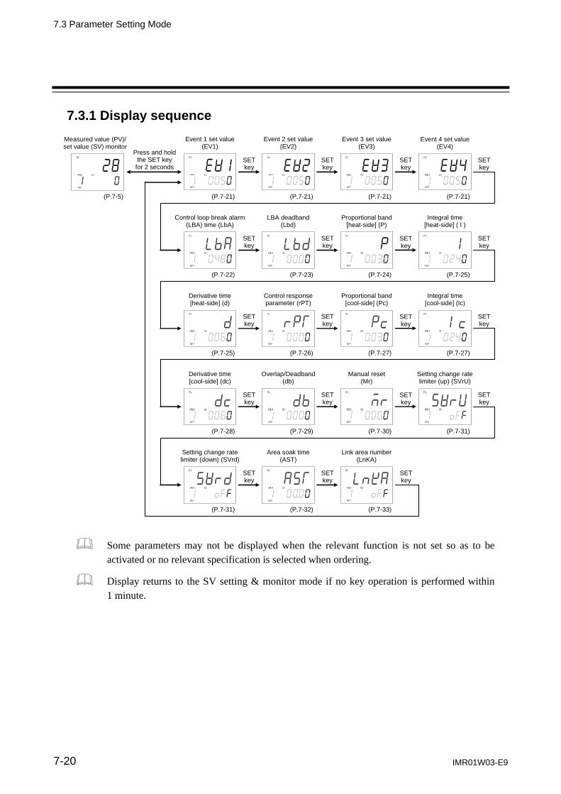
7.3 Parameter Setting Mode
IMR01W03-E9 7-20
7.3.1 Display sequence
Setting change rate limiter (down) (SVrd)
Area soak time (AST)
Link area number (LnKA)
Derivative time [cool-side] (dc)
Setting change rate limiter (up) (SVrU)
Overlap/Deadband (db)
Manual reset (Mr)
Derivative time [heat-side] (d)
Integral time [cool-side] (Ic)
Control response parameter (rPT)
Proportional band [cool-side] (Pc)
Control loop break alarm (LBA) time (LbA)
Integral time [heat-side] ( I )
LBA deadband (Lbd)
Proportional band [heat-side] (P)
Press and hold the SET key
for 2 seconds
Measured value (PV)/ set value (SV) monitor
SET key
SET key
SET key
Event 1 set value (EV1)
Event 4 set value (EV4)
Event 2 set value (EV2)
Event 3 set value (EV3)
SET key
SET key
SET key
SET key
SET key
SET key
SET key
SET key
SET key
SET key
SET key
SET key キ
SET key
SET key
SET key
(P.7-21) (P.7-21) (P.7-21) (P.7-21)(P.7-5)
(P.7-22) (P.7-23) (P.7-24) (P.7-25)
(P.7-25) (P.7-26) (P.7-27) (P.7-27)
(P.7-28) (P.7-29) (P.7-30) (P.7-31)
(P.7-31) (P.7-32) (P.7-33)
SET key
Some parameters may not be displayed when the relevant function is not set so as to be activated or no relevant specification is selected when ordering.
Display returns to the SV setting & monitor mode if no key operation is performed within 1 minute.

7.3 Parameter Setting Mode
IMR01W03-E9 7-21
7.3.2 Parameter setting item
Event 1 set value (EV1) Event 3 set value (EV3) Event 2 set value (EV2) Event 4 set value (EV4)
DATALOCK
MEMORY AREA
Digital output
OPTION
EV1 to EV4 are set values of the Event action. Signals are output from the digital outputs (DO1 to DO4) if exceeding the Event set value.
Data range Factory set value
When the event action is the deviation*: Input span to +Input span Varies with the setting of the Decimal point position (P. 7-71).
50
* Deviation: Deviation high, Deviation low, Deviation high/low and Band
When the event action is the input value or set value: Input scale low to Input scale high Varies with the setting of the Decimal point position (P. 7-71).
50
When the event action is the manipulated output value (MV1 or MV2): 5.0 to +105.0 %
50
These screens are not displayed when the type of the Event 1, 2, 3 and 4 is set to “0: None.”
The Event 4 set value (EV4) screen is not displayed when the Event 4 is used as a “9: Control loop break alarm (LBA).”
For the setting method of Event set value, refer to 6.3.2 Set the event set value (alarm set value) (P. 6-6).
Related parameters Engineering mode: Decimal point position (P. 7-71) Alarm (ALM) lamp lighting condition 1 (P. 7-81) Event 1 type (P. 7-85) Event 1 differential gap (P. 7-90) Event 2 type (P. 7-95) Event 2 differential gap (P. 7-99) Event 3 type (P. 7-102) Event 3 differential gap (P. 7-106) Event 4 type (P. 7-109) Event 4 differential gap (P. 7-113) Event 1 hold action (P. 7-87) Event 1 delay timer (P. 7-91) Event 2 hold action (P. 7-97) Event 2 delay timer (P. 7-100) Event 3 hold action (P. 7-104) Event 3 delay timer (P. 7-107) Event 4 hold action (P. 7-111) Event 4 delay timer (P. 7-114) Event 1 interlock (P. 7-89) Force ON of Event 1 action (P. 7-93) Event 2 interlock (P. 7-98) Force ON of Event 2 action (P. 7-101) Event 3 interlock (P. 7-105) Force ON of Event 3 action (P. 7-108) Event 4 interlock (P. 7-112) Force ON of Event 4 action (P. 7-115)
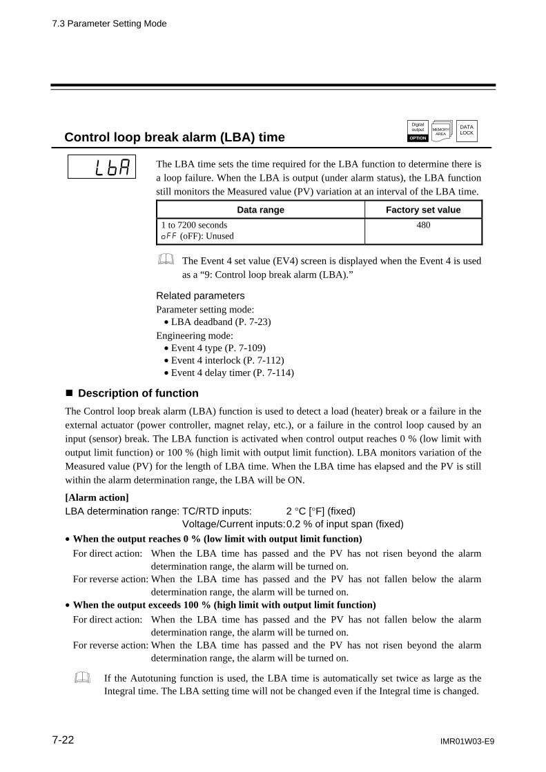
7.3 Parameter Setting Mode
IMR01W03-E9 7-22
Control loop break alarm (LBA) time DATA
LOCKMEMORY
AREA
Digital output
OPTION
The LBA time sets the time required for the LBA function to determine there is a loop failure. When the LBA is output (under alarm status), the LBA function still monitors the Measured value (PV) variation at an interval of the LBA time.
Data range Factory set value
1 to 7200 seconds oFF (oFF): Unused
480
The Event 4 set value (EV4) screen is displayed when the Event 4 is used as a “9: Control loop break alarm (LBA).”
Related parameters Parameter setting mode: LBA deadband (P. 7-23)
Engineering mode: Event 4 type (P. 7-109) Event 4 interlock (P. 7-112) Event 4 delay timer (P. 7-114)
Description of function
The Control loop break alarm (LBA) function is used to detect a load (heater) break or a failure in the external actuator (power controller, magnet relay, etc.), or a failure in the control loop caused by an input (sensor) break. The LBA function is activated when control output reaches 0 % (low limit with output limit function) or 100 % (high limit with output limit function). LBA monitors variation of the Measured value (PV) for the length of LBA time. When the LBA time has elapsed and the PV is still within the alarm determination range, the LBA will be ON.
[Alarm action] LBA determination range: TC/RTD inputs: 2 C [F] (fixed)
Voltage/Current inputs: 0.2 % of input span (fixed)
When the output reaches 0 % (low limit with output limit function) For direct action: When the LBA time has passed and the PV has not risen beyond the alarm
determination range, the alarm will be turned on. For reverse action: When the LBA time has passed and the PV has not fallen below the alarm
determination range, the alarm will be turned on. When the output exceeds 100 % (high limit with output limit function)
For direct action: When the LBA time has passed and the PV has not fallen below the alarm determination range, the alarm will be turned on.
For reverse action: When the LBA time has passed and the PV has not risen beyond the alarm determination range, the alarm will be turned on.
If the Autotuning function is used, the LBA time is automatically set twice as large as the Integral time. The LBA setting time will not be changed even if the Integral time is changed.
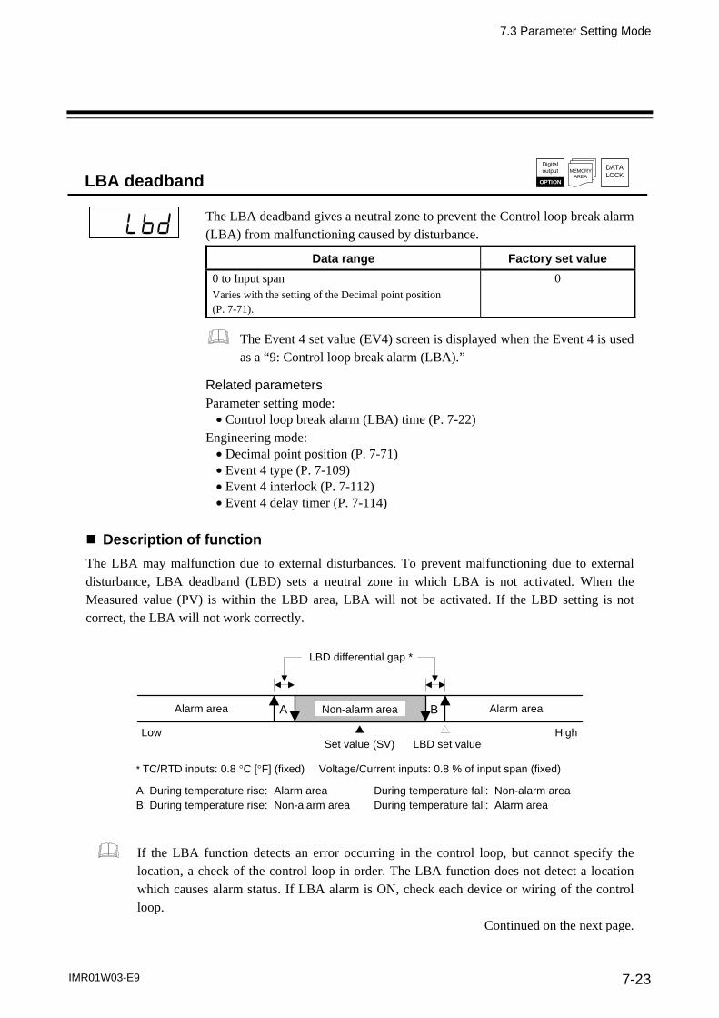
7.3 Parameter Setting Mode
IMR01W03-E9 7-23
LBA deadband DATA
LOCKMEMORY
AREA
Digital output
OPTION
The LBA deadband gives a neutral zone to prevent the Control loop break alarm (LBA) from malfunctioning caused by disturbance.
Data range Factory set value
0 to Input span Varies with the setting of the Decimal point position (P. 7-71).
0
The Event 4 set value (EV4) screen is displayed when the Event 4 is used as a “9: Control loop break alarm (LBA).”
Related parameters Parameter setting mode: Control loop break alarm (LBA) time (P. 7-22)
Engineering mode: Decimal point position (P. 7-71) Event 4 type (P. 7-109) Event 4 interlock (P. 7-112) Event 4 delay timer (P. 7-114)
Description of function
The LBA may malfunction due to external disturbances. To prevent malfunctioning due to external disturbance, LBA deadband (LBD) sets a neutral zone in which LBA is not activated. When the Measured value (PV) is within the LBD area, LBA will not be activated. If the LBD setting is not correct, the LBA will not work correctly.
* TC/RTD inputs: 0.8 C [F] (fixed) Voltage/Current inputs: 0.8 % of input span (fixed) A: During temperature rise: Alarm area During temperature fall: Non-alarm area B: During temperature rise: Non-alarm area During temperature fall: Alarm area
LBD differential gap *
Alarm area Alarm area Non-alarm areaA B
Set value (SV) LBD set valueLow High
If the LBA function detects an error occurring in the control loop, but cannot specify the location, a check of the control loop in order. The LBA function does not detect a location which causes alarm status. If LBA alarm is ON, check each device or wiring of the control loop.
Continued on the next page.

7.3 Parameter Setting Mode
IMR01W03-E9 7-24
Continued from the previous page.
LBA function is not operative when: AT function is activated. The controller is in STOP mode. The control type is Heat/Cool PID control. LBA function is set to “0.” LBA function is not assigned to Event 4 (ES4).
If the LBA time is too short or does not match the controlled object requirements, LBA may turn ON or OFF at inappropriate time or remain OFF. Change the LBA time based on the malfunction.
While the LBA is ON (under alarm status), the following conditions cancel the alarm status and LBA will be OFF: The Measured value (PV) rises beyond (or falls below) the LBA determination range
within the LBA time. The Measured value (PV) enter within the LBA deadband.
Proportional band [heat-side] DATA
LOCKMEMORY
AREA
This is a Proportional band in P, PI, PD or PID control. When in Heat/Cool PID control, it becomes the Proportional band on the heat side.
Data range Factory set value
TC/RTD inputs: 0 (0.0, 0.00) to Input span (Unit: C [F]) 0 (0.0, 0.00): ON/OFF action Varies with the setting of the Decimal point position (P. 7-71).
30 (30.0, 30.00)
Voltage (V)/Current (I) inputs: 0.0 to 1000.0 % of input splay 0.0: ON/OFF action
30.0
Related parameters Parameter setting mode: Overlap/Deadband (P. 7-29)
Engineering mode: Decimal point position (P. 7-71) ON/OFF action differential gap (upper), ON/OFF action differential gap (lower) (P. 7-134) Overlap/Deadband reference point (P. 7-144)
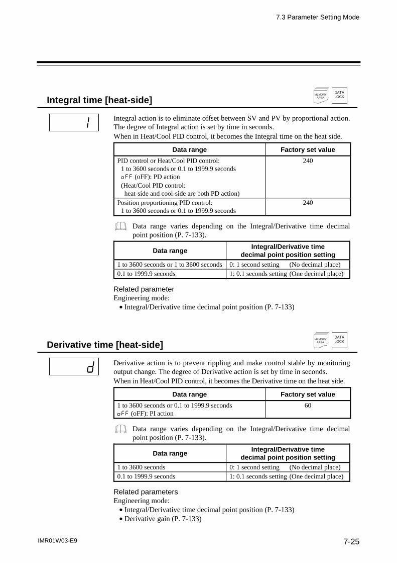
7.3 Parameter Setting Mode
IMR01W03-E9 7-25
Integral time [heat-side] DATA
LOCKMEMORY
AREA
Integral action is to eliminate offset between SV and PV by proportional action. The degree of Integral action is set by time in seconds. When in Heat/Cool PID control, it becomes the Integral time on the heat side.
Data range Factory set value
PID control or Heat/Cool PID control: 1 to 3600 seconds or 0.1 to 1999.9 seconds oFF (oFF): PD action
(Heat/Cool PID control: heat-side and cool-side are both PD action)
240
Position proportioning PID control: 1 to 3600 seconds or 0.1 to 1999.9 seconds
240
Data range varies depending on the Integral/Derivative time decimal point position (P. 7-133).
Data range Integral/Derivative time
decimal point position setting
1 to 3600 seconds or 1 to 3600 seconds 0: 1 second setting (No decimal place) 0.1 to 1999.9 seconds 1: 0.1 seconds setting (One decimal place)
Related parameter Engineering mode: Integral/Derivative time decimal point position (P. 7-133)
Derivative time [heat-side] DATA
LOCKMEMORY
AREA
Derivative action is to prevent rippling and make control stable by monitoring output change. The degree of Derivative action is set by time in seconds. When in Heat/Cool PID control, it becomes the Derivative time on the heat side.
Data range Factory set value
1 to 3600 seconds or 0.1 to 1999.9 seconds oFF (oFF): PI action
60
Data range varies depending on the Integral/Derivative time decimal point position (P. 7-133).
Data range Integral/Derivative time
decimal point position setting
1 to 3600 seconds 0: 1 second setting (No decimal place) 0.1 to 1999.9 seconds 1: 0.1 seconds setting (One decimal place)
Related parameters Engineering mode: Integral/Derivative time decimal point position (P. 7-133) Derivative gain (P. 7-133)
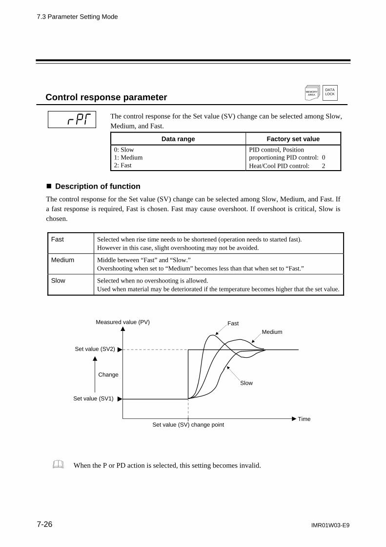
7.3 Parameter Setting Mode
IMR01W03-E9 7-26
Control response parameter DATA
LOCKMEMORY
AREA
The control response for the Set value (SV) change can be selected among Slow, Medium, and Fast.
Data range Factory set value
0: Slow 1: Medium 2: Fast
PID control, Position proportioning PID control: 0 Heat/Cool PID control: 2
Description of function
The control response for the Set value (SV) change can be selected among Slow, Medium, and Fast. If a fast response is required, Fast is chosen. Fast may cause overshoot. If overshoot is critical, Slow is chosen.
Fast Selected when rise time needs to be shortened (operation needs to started fast). However in this case, slight overshooting may not be avoided.
Medium Middle between “Fast” and “Slow.” Overshooting when set to “Medium” becomes less than that when set to “Fast.”
Slow Selected when no overshooting is allowed. Used when material may be deteriorated if the temperature becomes higher that the set value.
Measured value (PV)
Set value (SV2)
Change
Set value (SV) change point Time
Fast
Medium
Slow
Set value (SV1)
When the P or PD action is selected, this setting becomes invalid.

7.3 Parameter Setting Mode
IMR01W03-E9 7-27
Proportional band [cool-side] DATA
LOCKMEMORY
AREA
This is a Proportional band for the cool side in Heat/Cool P, PI, PD or PID control.
Data range Factory set value
TC/RTD inputs: 1 (0.1, 0.01) to Input span (Unit: C [F])
Varies with the setting of the Decimal point position (P. 7-71).
30 (30.0, 30.00)
Voltage (V)/Current (I) inputs: 0.1 to 1000.0 % of input span
30.0
This screen is displayed when in Heat/Cool PID control.
Related parameters Parameter setting mode: Overlap/Deadband (P. 7-29)
Engineering mode: Decimal point position (P. 7-71) Control action (P. 7-129) Overlap/Deadband reference point (P. 7-144)
Integral time [cool-side] DATA
LOCKMEMORY
AREA
Integral action [cool-side] is to eliminate offset between SV and PV by proportional action of cool-side. he degree of Integral action [cool-side] is set by time in seconds.
Data range Factory set value
1 to 3600 seconds or 0.1 to 1999.9 seconds oFF (oFF): PD action (Heat/Cool PID control:
heat-side and cool-side are both PD action)
240
Data range varies depending on the Integral/Derivative time decimal point position (P. 7-133).
Data range Integral/Derivative time
decimal point position setting
1 to 3600 seconds 0: 1 second setting (No decimal place) 0.1 to 1999.9 seconds 1: 0.1 seconds setting (One decimal place)
This screen is displayed when in Heat/Cool PID control.
Related parameters Engineering mode: Control action (P. 7-129) Integral/Derivative time decimal point position (P. 7-133)

7.3 Parameter Setting Mode
IMR01W03-E9 7-28
Derivative time [cool-side] DATA
LOCKMEMORY
AREA
Derivative action of cool-side is to prevent rippling and make control stable by monitoring output change. The degree of Derivative action [cool-side] is set by time in seconds.
Data range Factory set value
1 to 3600 seconds or 0.1 to 1999.9 seconds oFF (oFF): PI action
60
Data range varies depending on the Integral/Derivative time decimal point position (P. 7-133).
Data range Integral/Derivative time
decimal point position setting
1 to 3600 seconds 0: 1 second setting (No decimal place) 0.1 to 1999.9 seconds 1: 0.1 seconds setting (One decimal place)
This screen is displayed when in Heat/Cool PID control.
Related parameters Engineering mode: Control action (P. 7-129) Integral/Derivative time decimal point position (P. 7-133) Derivative gain (P. 7-133)

7.3 Parameter Setting Mode
IMR01W03-E9 7-29
Overlap/Deadband DATA
LOCKMEMORY
AREA
This is the overlapped range of Proportional bands (on the heat and cool sides) or the deadband range when Heat/Cool PID control is performed.
Data range Factory set value
TC/RTD inputs: Input span to +Input span (Unit: C [F]) Varies with the setting of the Decimal point position (P. 7-71).
0
Voltage (V)/Current (I) inputs: 100.0 to +100.0 % of Input span
0.0
Minus () setting results is Overlap. However, the overlapping range is limited to the Proportional band [heat-side] set range or the Proportional band [cool-side] set range, whichever is smaller.
This screen is displayed when in Heat/Cool PID control.
Related parameters Parameter setting mode: Proportional band [heat-side] (P. 7-24) Proportional band [cool-side] (P. 7-27)
Engineering mode: Decimal point position (P. 7-71) Control action (P. 7-129) Overlap/Deadband reference point (P. 7-144)
Description of function Overlap (OL): Range in which the Proportional band [heat-side] and the Proportional band
[cool-side] are overlapped. If a Measured value (PV) is within the overlapped range, Manipulated output values (MV1 and MV2) may be simultaneously output.
Deadband (DB): This is a control dead zone existing between the Proportional band [heat-side] and the Proportional band [cool-side]. If a Measured value (PV) is within the deadband range, neither the Manipulated output value (MV1) nor the Manipulated output value (MV2) is output.
Manipulated output value (MV)
100 %
0 %
Heat-side output value
Proportional band [heat-side]
Cool-side output value
Set value (SV)
OL DB DB: Deadband
Temperature
If set to minus (-), the proportional band (on the cool side) overlaps with the proportional band (on the heat side).
Proportional band[cool-side]
OL: Overlap
The diagram is an example when setting 0.0 to the Overlap/Deadband reference point. For Overlap/Deadband reference point, refer to P. 7-144.

7.3 Parameter Setting Mode
IMR01W03-E9 7-30
Manual reset
DATALOCK
MEMORY AREA
In order to eliminate the offset occurring in Proportional (P) control, the Manipulated output value is manually corrected. When the Manual reset is set to the plus (+) side:
The Manipulated output value under the stable condition increases by the Manual reset value.
When the Manual reset is set to the minus () side: The Manipulated output value under the stable condition decreases by the Manual reset value.
Data range Factory set value
100.0 to +100.0 % 0.0
This screen is displayed when the Integral time [heat-side or cool-side] is turned off.
Related parameters Parameter setting mode: Integral time [heat-side] (P. 7-25) Integral time [cool-side] (P. 7-27)
Description of function
This is the function used to manually correct the offset when in Proportional (P) control or PD control. Offset means the deviation of the actual when the Manipulated output value becomes stabilized (stable state). If the Manual reset value varies, the Manipulated output value also changes.
Set value (SV)
Offset
Measured value (PV)
Temperature
Time
Measured value (PV)
Offset
Manual reset is set.

7.3 Parameter Setting Mode
IMR01W03-E9 7-31
Setting change rate limiter (up) Setting change rate limiter (down)
DATALOCK
MEMORY AREA
This function is to allow the Set value (SV) to be automatically changed at specific rates when a new Set value (SV). SVrU is used when the SV is changed to a higher SV. SVrd is used when the SV is changed to a lower SV.
Data range Factory set value
1 (0.1, 0.01) to Input span/unit time oFF (oFF): Unused Varies with the setting of the Decimal point position (P. 7-71).
oFF (oFF)
The unit time of the Setting change rate limiter can be change in the range of 1 to 3600 seconds. The unit time is set on the Setting change rate limiter unit time (P. 7-169).
Related parameter Engineering mode: Decimal point position (P. 7-71) Setting change rate limiter unit time (P. 7-169)
Description of function This function is to allow the Set value (SV) to be automatically changed at specific rates when a new Set value (SV). SVrU is used when the SV is changed to a higher SV. SVrd is used when the SV is changed to a lower SV.
[Application examples of Setting change rate limiter]
SV
Decrease gradually
at specific rate
SV [After changing]
SV [Before changing]
Changing the set value
Time
Decreasing the SV to a lower value
Increase gradually
at specific rate
Changing the set value
SV [After changing]
SV [Before changing]
Time
Increasing the SV to a higher value
SV
When the Setting change rate limiter is used, the SV will also ramp up or ramp down by the function at power-on and operation mode change from STOP to RUN.
If the Autotuning (AT) function is activated while the SV is ramping up or ramping down by the Setting change rate limiter, AT will starts after the SV finishes ramp-up or ramp-down by the limiter, and the controller is in PID control mode until AT starts.
When the value of Setting change rate limiter is changed during normal operation, the ramp-up or ramp-down rate will be changed unless the SV already has finished ramp-up or ramp-down by the function.
If the rate of Setting change limiter is set to any value other than “OFF (Unused),” the event re-hold action to be taken by a Set value (SV) change becomes invalid.

7.3 Parameter Setting Mode
IMR01W03-E9 7-32
Area soak time DATA
LOCKMEMORY
AREA
This is the time required until transferred to the Link area number when performing Ramp/Soak control.
Data range Factory set value
0 minutes 00 seconds to 199 minutes 59 seconds 0 hours 00 minutes to 99 hours 59 minutes
0:00
Data range is selected on the Soak time unit (P. 7-169).
Related parameter Parameter setting mode: Engineering mode: Link area number (P. 7-33) Soak time unit (P. 7-169)
Description of function
Area soak time is used for Ramp/Soak control function in conjunction with Link area number and Setting change rate limiter (up/down).
[Application examples of Area soak time]
Measured value (PV)
Set value (SV) of memory area 1
Memory area 1
Area soak time ofmemory area 1
Setting change rate limiter (up)of memory area1
Area soak time ofmemory area 2
Setting change rate limiter(up) of memory area 2
Time
Set value (SV) of memory area 2
Memory area 2
The Area soak time for the memory area linked last becomes invalid to continue the state of the Set value (SV) reached.
Time required while the Setting change rate limiter is being operated is not included in the Area soak time.
The Area soak time can be changed during normal operation with Ramp/Soak control function, but read the following example carefully how the time change affects Ramp/Soak control time. For example, the memory area which has 5-minute soak time is executed. When 3 minutes passed, the Area soak time is changed from 5 minutes to 10 minutes. The remaining time of the currently executed memory area is computed as follows. (The new soak time 10 minutes) – (lapsed time 3 minutes) = (remaining time 7 minutes) The old soak time does not have any effect on remaining time.
Area soak time:
5 minutes
Area soak time is changed 10 minutes.
Measured value (PV)
Set value (SV) of memory area 1
Present set value (SV)
Time
Operationstart: 3 minutes
Time of remaining operating hour:
7 minutes
Changing

7.3 Parameter Setting Mode
IMR01W03-E9 7-33
Link area number DATA
LOCKMEMORY
AREA
Memory area numbers for linking the corresponding memory areas are set when Ramp/Soak control is performed.
Data range Factory set value
1 to 8 oFF (oFF): No link
oFF (oFF)
Related parameter Parameter setting mode: Area soak time (P. 7-32)
Engineering mode: Soak time unit (P. 7-169)
Description of function
Link area number is used for Ramp/Soak control function in conjunction with Area soak time and Setting change rate limiter (up/down).
Area soak time of memory area 1
Area soak time ofmemory area 2
Setting change rate limiter (down) of memory area 3
Area soak time of memory area 3
Measured value (PV)
Set value (SV) of memory area 2
Set value (SV) of memory area 1
Set value (SV) of memory area 3
Present set value (SV)
TimeMemory area 2 Memory area 3 Memory area 1
Setting change rate limiter (up) of memory area 2
Setting change rate limiter (up) of memory area 1
The Area soak time for the memory area linked last becomes invalid to continue the state of the Set value (SV) reached.

7. PARAMETER DESCRIPTION
7-34 IMR01W03-E9
7.4 Setup Setting Mode
In Setup setting mode, the following operations are possible. Change other operation/control related parameters Change Communication parameters Change Data lock level
7.4.1 Display sequence
Press the shift key
while pressing the SET key
Measured value (PV)/ Set value (SV) monitor
SETkey
SET key
Heater break alarm 1 (HBA1) set value
(HbA1)
Heater break alarm 2 (HBA2) set value
(HbA2)
SETkey
Heater break determination point 1
(HbL1)
Heater melting determination point 1
(HbH1)
SETkey
SET key
Heater break determination point 2
(HbL2)
PV digital filter
(dF)
SETkey
Heater melting determination point 2
(HbH2)
PV bias
(Pb)
SETkey
SET key
PV ratio
(Pr)
RS digital filter
(dF2)
SETkey
PV low input cut-off
(PLC)
RS bias
(rb)
SETkey
SET key
SETkey
SETkey
SET key
Communication speed 1
(bPS1)
Device address 2
(Add2)
SETkey
Interval time 1
(InT1)
SETkey
SET key
Communication speed 2
(bPS2)
Set lock level
(LCK)
SETkey
RS ratio
(rr)
Device address 1
(Add1)
Proportional cycle time [heat-side]
(T)
Proportional cycle time [cool-side]
( t )
Data bit configuration 1
(bIT1)
Data bit configuration 2
(bIT2)
Interval time 2
(InT2)
SETkey
SETkey
SETkey
SETkey
SETkey
SETkey
(P.7-35) (P.7-38) (P.7-39) (P.7-35)(P.7-5)
(P.7-38) (P.7-39) (P.7-40) (P.7-40)
(P.7-40) (P.7-41) (P.7-42) (P.7-42)
(P.7-42) (P.7-43) (P.7-43) (P.7-44)
(P.7-44) (P.7-45) (P.7-46) (P.7-44)
(P.7-44) (P.7-45) (P.7-46) (P.7-47)
Some parameters may not be displayed when the relevant function is not set so as to be activated or no relevant specification is selected when ordering.
Display returns to the SV setting & monitor mode if no key operation is performed within 1 minute.
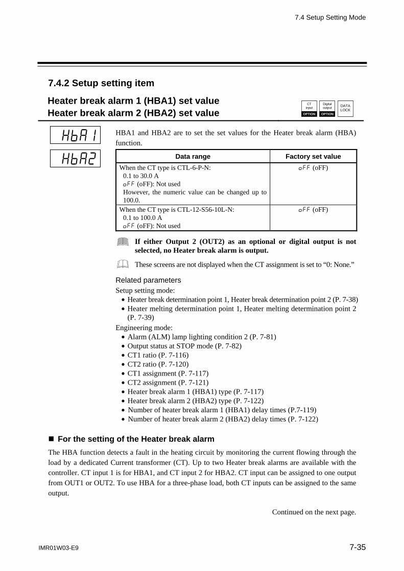
7.4 Setup Setting Mode
IMR01W03-E9 7-35
7.4.2 Setup setting item
Heater break alarm 1 (HBA1) set value Heater break alarm 2 (HBA2) set value
DATALOCK
CT input
OPTION
Digital output
OPTION
HBA1 and HBA2 are to set the set values for the Heater break alarm (HBA) function.
Data range Factory set value
When the CT type is CTL-6-P-N: 0.1 to 30.0 A oFF (oFF): Not used However, the numeric value can be changed up to 100.0.
oFF (oFF)
When the CT type is CTL-12-S56-10L-N: 0.1 to 100.0 A oFF (oFF): Not used
oFF (oFF)
If either Output 2 (OUT2) as an optional or digital output is not selected, no Heater break alarm is output.
These screens are not displayed when the CT assignment is set to “0: None.”
Related parameters Setup setting mode: Heater break determination point 1, Heater break determination point 2 (P. 7-38) Heater melting determination point 1, Heater melting determination point 2
(P. 7-39) Engineering mode: Alarm (ALM) lamp lighting condition 2 (P. 7-81) Output status at STOP mode (P. 7-82) CT1 ratio (P. 7-116) CT2 ratio (P. 7-120) CT1 assignment (P. 7-117) CT2 assignment (P. 7-121) Heater break alarm 1 (HBA1) type (P. 7-117) Heater break alarm 2 (HBA2) type (P. 7-122) Number of heater break alarm 1 (HBA1) delay times (P.7-119) Number of heater break alarm 2 (HBA2) delay times (P. 7-122)
For the setting of the Heater break alarm
The HBA function detects a fault in the heating circuit by monitoring the current flowing through the load by a dedicated Current transformer (CT). Up to two Heater break alarms are available with the controller. CT input 1 is for HBA1, and CT input 2 for HBA2. CT input can be assigned to one output from OUT1 or OUT2. To use HBA for a three-phase load, both CT inputs can be assigned to the same output.
Continued on the next page.

7.4 Setup Setting Mode
IMR01W03-E9 7-36
Continued from the previous page. Two types of Heater break alarms, type A and type B, are available. An appropriate type should be selected depending on the application. (Please refer to “Heater break alarm function” below.) These parameters, HBA set values (HbA1 and HbA2) are used for both types. However, each type has different function and care must be used to set an appropriate set value. For type A HBA, - Set the set value to approximately 85 % of the maximum reading of the CT input. - Set the set value to a slightly smaller value to prevent a false alarm if the power supply may become
unstable. - When more than one heater is connected in parallel, it may be necessary to increase the HBA set
value to detect a single heater failure.
For type B HBA, Set the set value to the maximum CT input value. This will be the current when the control is at 100 % control output. The set value is used to compute the width of a non-alarm range.
Description of function
< Heater break alarm (HBA) type A > Heater break alarm (HBA) type A can be used with time-proportional control output (Relay contact, Voltage pulse, Triac or Open collector output). The HBA function monitors the current flowing through the load by a dedicated Current transformer (CT), compares the measured value with the HBA set values, and detects a fault in the heating circuit. Low or No current flow (Heater break, malfunction of the control device, etc.):
When the control output is ON and the CT input value is equal to or less than the Heater break determination point for the preset number of consecutive sampling cycles, an alarm is activated.
Over current or short-circuit:
When the control output is OFF and the CT input value is equal to or greater than the Heater break determination point for the preset number of consecutive sampling cycles, an alarm is activated.
< Heater break alarm (HBA) type B > Heater break alarm (HBA) type B can be used with continuous control output (Voltage/Current continuous output). The HBA function assumes that the heater current value is proportional* to the control output value of the controller, otherwise viewed as the Manipulated output value (MV), and compare it with the CT input value to detect a fault in the heating or cooling circuit. * It is assumed that the current value flowing through the load is at maximum when the control output from
the controller is 100 %, and the minimum current value flowing through the load is zero (0) when the control output from the controller is 0 %.
Continued on the next page.

7.4 Setup Setting Mode
IMR01W03-E9 7-37
Continued from the previous page. Low or No current flow (Heater break, malfunction of the control device, etc.)
The alarm determination point (Low) is computed as follows: [Non-alarm range (Low) width] = (HbL1 or HbL2) (HbA1 or HbA2) [Alarm determination point (Low)] = [(HbA1 or HbA2) (MV1 or MV2)] – [Non-alarm range (Low) width] When the CT input value is equal to or less than the Heater break determination point for the preset number of consecutive sampling cycles, an alarm status is produced.
Over current or short-circuit
The alarm determination point (High) is computed as follows: [Non-alarm range (High) width] = (HbH1 or HbH2) (HbA1 or HbA2) [Alarm determination point (High)] = [(HbA1 or HbA2) (MV1 or MV2)] + [Non-alarm range (High) width] When the CT input value is equal to or greater than the Heater melting determination point for the preset number of consecutive sampling cycles, an alarm status is produced.
Computed heater current value (Proportional to voltage squared)
Alarm range ofLow current/ No current
Alarm range ofOver current/Short-circuit
Current value of heater used (squared)
Manipulated output value of controller
Non-alarm range (High) for heater melting determination
100 [%]
0 [%]
0 [A]
Maximum current value (squared)
Non-alarm range (Low) for heater break determination
Heater melting determination point
(0.0 to 100.0 % of maximum current) Heater break
determination point (0.0 to 100.0 % of maximum current)
The current factory set values of HbLs and HbHs are set to 30.0 %. If any of the following conditions exists, set them to a slightly larger value to prevent a false alarm. Heater current values is not proportional to the control output in Phase control. There is difference on control output accuracy between the controller and the
operating unit (SCR Power Controller). There is a delay on control output between the controller and the operating unit
(SCR Power Controller).
Factory set value of Heater break alarm (HBA) varies with the control output type of CT assignment. Factory set value (CT assignment: OUT1) of Heater break alarm 1 (HBA1) type: OUT1 output type: Time-proportional control output *: Type A Continuous control output *: Type B Factory set value (CT assignment: None) of Heater break alarm 2 (HBA2) type: Type A
* Time-proportional control output: Relay contact, Voltage pulse, Triac or Open collector output Continuous control output: Voltage/Current continuous output

7.4 Setup Setting Mode
IMR01W03-E9 7-38
Heater break determination point 1 Heater break determination point 2
DATALOCK
CT input
OPTION
Digital output
OPTION
Set the Heater break determination point for the Heater break alarm (HBA) type B.
Data range Factory set value
Heater break determination point 1: 0.1 to 100.0 % of Heater break alarm 1 (HBA1) set value oFF (oFF): Heater break determination is invalid
30.0
Heater break determination point 2: 0.1 to 100.0 % of Heater break alarm 2 (HBA2) set value oFF (oFF): Heater break determination is invalid
30.0
The Heater break determination point 1 or 2 screen is not displayed when CT assignment is set to “0: None.”
The Heater break determination point 1 or 2 screen is displayed when the Heater break alarm type is type B.
Related parameters Setup setting mode: Heater break alarm 1 (HBA1) set value,
Heater break alarm 2 (HBA2) set value (P. 7-35) Heater melting determination point 1,
Heater melting determination point 2 (P. 7-39) Engineering mode: CT1 assignment (P. 7-117) CT2 assignment (P. 7-121) Heater break alarm 1 (HBA1) type (P. 7-117) Heater break alarm 2 (HBA2) type (P. 7-122) Number of heater break alarm 1 (HBA1) delay times (P. 7-119) Number of heater break alarm 2 (HBA2) delay times (P. 7-122)
For the function description, refer to the Heater break alarm 1 (HBA1) set value/Heater break alarm 2 (HBA2) set value (P.7-35).

7.4 Setup Setting Mode
IMR01W03-E9 7-39
Heater melting determination point 1 Heater melting determination point 2
DATALOCK
CT input
OPTION
Digital output
OPTION
Set the Heater melting determination point for the Heater break alarm (HBA) type B.
Data range Factory set value
Heater melting determination point 1: 0.1 to 100.0 % of Heater break alarm 1 (HBA1) set value oFF (oFF): Heater melting determination is invalid
30.0
Heater melting determination point 2: 0.1 to 100.0 % of Heater break alarm 2 (HBA2) set value oFF (oFF): Heater melting determination is invalid
30.0
The Heater melting determination point 1 or 2 screen is not displayed when CT assignment is set to “0: None.”
The Heater melting determination point 1 or 2 screen is displayed when the Heater break alarm type is type B.
Related parameters Setup setting mode: Heater break alarm 1 (HBA1) set value,
Heater break alarm 2 (HBA2) set value (P. 7-35) Heater break determination point 1,
Heater break determination point 2 (P. 7-38) Engineering mode: CT1 assignment (P. 7-117) CT2 assignment (P. 7-121) Heater break alarm 1 (HBA1) type (P. 7-117) Heater break alarm 2 (HBA2) type (P. 7-122) Number of heater break alarm 1 (HBA1) delay times (P. 7-119) Number of heater break alarm 2 (HBA2) delay times (P. 7-122)
For the function description, refer to the Heater break alarm 1 (HBA1) set value/Heater break alarm 2 (HBA2) set value (P.7-35).

7.4 Setup Setting Mode
IMR01W03-E9 7-40
PV bias DATA
LOCK
PV bias adds bias to the Measured value (PV). The PV bias is used to compensate the individual variations of the sensors or correct the difference between the Measured value (PV) of other instruments.
Data range Factory set value
Input span to +Input span Varies with the setting of the Decimal point position (P. 7-71).
0
Related parameters Engineering mode: Decimal point position (P. 7-71)
PV digital filter DATA
LOCK
This item is the time of the first-order lag filter to eliminate noise against the measured input.
Data range Factory set value
0.1 to 100.0 seconds oFF (oFF): Unused
oFF (oFF)
PV ratio DATA
LOCK
PV ratio is a multiplier to be applied to the Measured value (PV). The PV ratio is used to compensate the individual variations of the sensors or correct the difference between the Measured value (PV) of other instruments.
Data range Factory set value
0.500 to 1.500 1.000

7.4 Setup Setting Mode
IMR01W03-E9 7-41
PV low input cut-off DATA
LOCK
PV low input cut-off is used with Square root extraction function. The Measured value less than the PV low input cut-off is ignored to prevent control disturbance caused by input variation at Low measured value range.
Data range Factory set value
0.00 to 25.00 % of input span 0.00
This screen is displayed when the Square root extraction is set to “1: Used.”
Related parameter Engineering mode: Square root extraction (P. 7-75)
Description of function
When input signal square root extraction is used for in flow control, etc., the Square root extraction result varies widely at the Low measured value range. The Measured value less than the PV low input cut-off is ignored to compute control output in order to prevent control disturbance caused by input variation at Low measured value range.
100 %
70.7 %
50 %
Output
Input 100 %50 %25 %
When set value of the PV low input cut-off is 15 %
0 %
When set value of the PV low input cut-off is 0 %

7.4 Setup Setting Mode
IMR01W03-E9 7-42
RS bias DATA
LOCK
RS bias adds bias to the Remote setting (RS) input value.
Data range Factory set value
Input span to +Input span Varies with the setting of the Decimal point position (P. 7-71).
0
The RS bias screen is displayed when the Remote setting (RS) input is provided.
If the Intercontroller communication control, the RS bias is used as a cascade bias.
If the Intercontroller communication control, the RS bias is used as a ratio setting bias.
Related parameters Engineering mode: Decimal point position (P. 7-71)
RS digital filter DATA
LOCK
This item is the time of the first-order lag filter to eliminate noise against the remote setting input.
Data range Factory set value
0.1 to 100.0 seconds oFF (oFF): Unused
oFF (oFF)
The RS digital filter screen is displayed when the Remote setting (RS) input is provided.
If the Intercontroller communication control, the RS digital filter is used as a cascade digital filter.
If the Intercontroller communication control, the RS digital filter is used as a ratio setting digital filter.
RS ratio DATA
LOCK
RS ratio is a multiplier to be applied to the Remote setting (RS) input value.
Data range Factory set value
0.001 to 9.999 1.000
The RS ratio screen is displayed when the Remote setting (RS) input is provided.
If the Intercontroller communication control, the RS ratio is used as a cascade ratio.
If the Intercontroller communication control, the RS ratio is used as a ratio setting ratio.
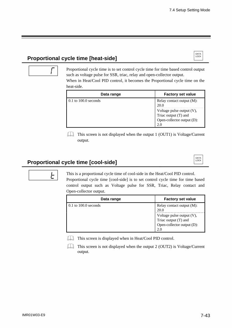
7.4 Setup Setting Mode
IMR01W03-E9 7-43
Proportional cycle time [heat-side] DATA
LOCK
Proportional cycle time is to set control cycle time for time based control output such as voltage pulse for SSR, triac, relay and open-collector output. When in Heat/Cool PID control, it becomes the Proportional cycle time on the heat-side.
Data range Factory set value
0.1 to 100.0 seconds Relay contact output (M): 20.0
Voltage pulse output (V), Triac output (T) and Open-collector output (D): 2.0
This screen is not displayed when the output 1 (OUT1) is Voltage/Current output.
Proportional cycle time [cool-side] DATA
LOCK
This is a proportional cycle time of cool-side in the Heat/Cool PID control. Proportional cycle time [cool-side] is to set control cycle time for time based control output such as Voltage pulse for SSR, Triac, Relay contact and Open-collector output.
Data range Factory set value
0.1 to 100.0 seconds Relay contact output (M): 20.0
Voltage pulse output (V), Triac output (T) and Open-collector output (D): 2.0
This screen is displayed when in Heat/Cool PID control.
This screen is not displayed when the output 2 (OUT2) is Voltage/Current output.

7.4 Setup Setting Mode
IMR01W03-E9 7-44
Device address 1 Device address 2
DATALOCK
Communi-cation
OPTION
Device address 1: Device address 1 is used to set the slave address of the controller for Communication 1 function.
Device address 2: Device address 2 is used to set the slave address of the controller for Communication 2 function. Device address 2 is also used for the address setting when the Intercontroller communication function is used.
Data range Factory set value
0 to 99 0
Do not use the same device address for more than one controller in multi-drop connection. Each controller must have a unique address in multi-drop connection.
When using the Intercontroller communication function, set Device address 2 to any number in the range of 0 to 31. In addition, always set the address of each controller to the number in succession starting from 0.
In Modbus communication, two-way communication is not possible when the address is 0.
For details of the Intercontroller communication function, refer to 6.14 Group Operation by the Intercontroller Communication (P. 6-60).
For details of the communication function, refer to the separate FB100/ FB400/FB900 Communication Instruction Manual (IMR01W04-E).
Communication speed 1 Communication speed 2
DATALOCK
Communi-cation
OPTION
Communication speed 1: Communication speed 1 is to set communication speed for Communication 1 function.
Communication speed 2: Communication speed 2 is to set communication speed for Communication 2 function.
Data range Factory set value
2.4: 2400 bps 9.6: 9600 bps 38.4: 38400 bps 4.8: 4800 bps 19.2: 19200 bps
19.2
Communication speed 2 screen is not displayed, when the communication 2 protocol is selected to Intercontroller communication protocol (P. 7-168).
For details of the Communication function, refer to the separate FB100/ FB400/FB900 Communication Instruction Manual (IMR01W04-E).

7.4 Setup Setting Mode
IMR01W03-E9 7-45
Data bit configuration 1 Data bit configuration 2
DATALOCK
Communi-cation
OPTION
Data bit configuration 1: This item is Data bit configuration of Communication 1 function.
Data bit configuration 2: This item is Data bit configuration of Communication 2 function.
Set value Data bit configuration Modbus
Communication RKC
CommunicationData Stop Parity
8n1 8 1 Without
Selectable
Selectable
8n2 8 2 Without
8E1 8 1 Even
8E2 8 2 Even
8o1 8 1 Odd
8o2 8 2 Odd
7n1 7 1 Without
Invalid
7n2 7 2 Without
7E1 7 1 Even
7E2 7 2 Even
7o1 7 1 Odd
7o2 7 2 Odd
Factory set value: 8n1 (Data bit: 8, Stop bit: 1, Parity bit: Without)
Data bit configuration 2 screen is not displayed, when the Communication 2 protocol is selected to Intercontroller communication protocol (P. 7-168).
For details of the Communication function, refer to the separate FB100/ FB400/FB900 Communication Instruction Manual (IMR01W04-E).

7.4 Setup Setting Mode
IMR01W03-E9 7-46
Interval time 1 Interval time 2
DATALOCK
Communi-cation
OPTION
Interval time 1: This item is Interval time of Communication 1 function. Interval time 2: This item is Interval time of Communication 2 function.
Data range Factory set value
0 to 250 ms 10
These screens are not displayed when the Intercontroller communication protocol is selected. (Refer to P. 7-168)
For details of the Communication function, refer to the separate FB100/ FB400/FB900 Communication Instruction Manual (IMR01W04-E).
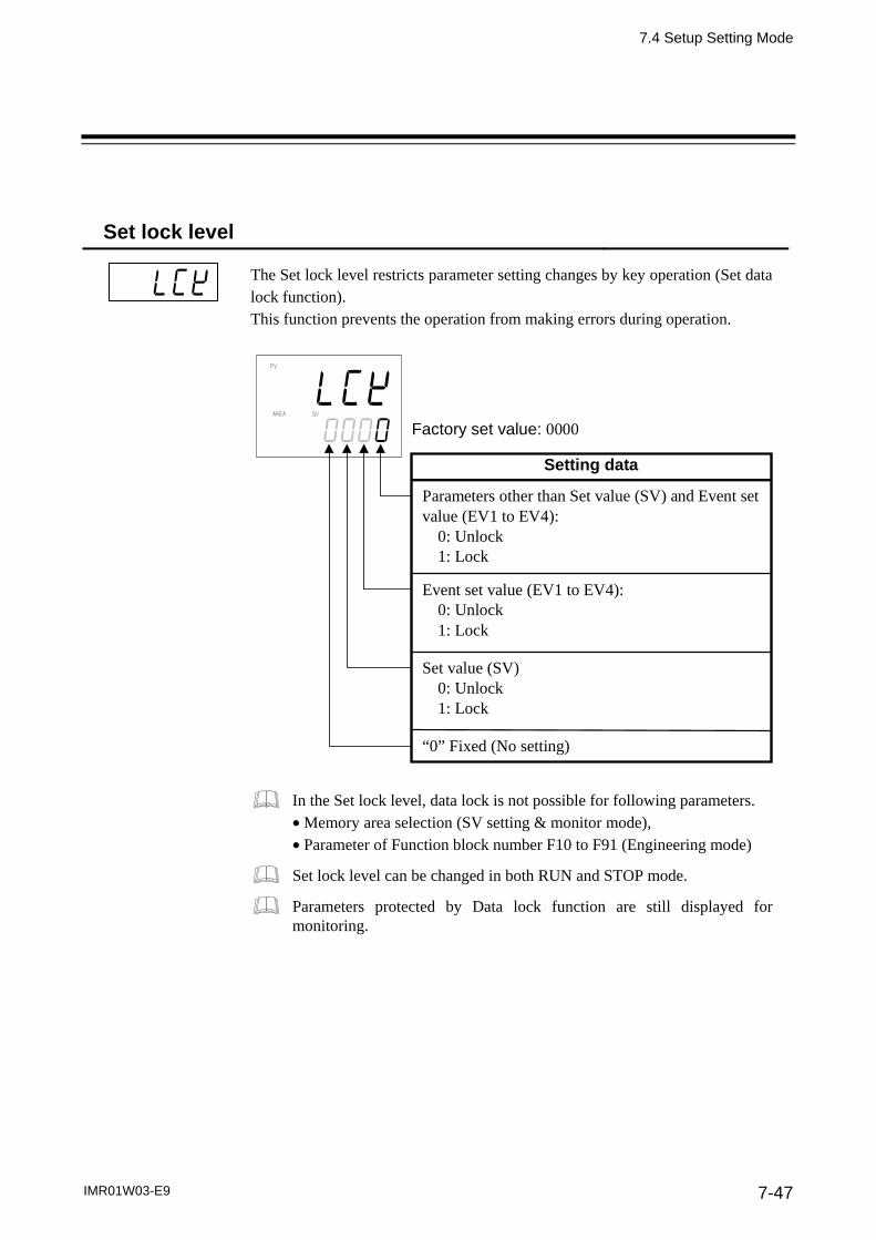
7.4 Setup Setting Mode
IMR01W03-E9 7-47
Set lock level
The Set lock level restricts parameter setting changes by key operation (Set data lock function). This function prevents the operation from making errors during operation.
Parameters other than Set value (SV) and Event set value (EV1 to EV4):
0: Unlock 1: Lock
Event set value (EV1 to EV4): 0: Unlock 1: Lock
Set value (SV) 0: Unlock 1: Lock
“0” Fixed (No setting)
Factory set value: 0000
Setting data
In the Set lock level, data lock is not possible for following parameters. Memory area selection (SV setting & monitor mode), Parameter of Function block number F10 to F91 (Engineering mode)
Set lock level can be changed in both RUN and STOP mode.
Parameters protected by Data lock function are still displayed for monitoring.

7. PARAMETER DESCRIPTION
7-48 IMR01W03-E9
7.5 Engineering Mode
The content relating to the specification of this product is set. Set it so as to meet the customer’s requirements. For details of the parameter, refer to the 7.5.3 Engineering item list (P. 7-62).
Parameters in Engineering mode are settable only when the controller is in STOP mode. However, only checking can be made even in the RUN state.
All parameters of the Engineering mode are displayed regardless of the instrument specification. 7.5.1 Display Sequence
SET key Return to F10.
screen.
Measured value (PV)/ Set value (SV) monitor
SETkey
Bar graph display resolution (dEUT)
PV flashing display at input error (dSoP)
STOP display (SPCH)
UP key
DOWN key
Press the shift key for 2 seconds while pressing the SET key
SET key
SETkey
Bar graph display(dE)
SET key
SET key
SETkey
SETkey Return to F11.
screen.
Function block 10 (F10.)
Function block 11 (F11.)
Direct key 1 (Fn1)
Direct key 2 (Fn2)
Direct key 3 (Fn3)
Direct key type (Fn)
UP key
DOWN key
Function block 21 (F21.)
Setup setting mode or
Parameter setting mode (P. 7-5)
(P. 7-62)
(P. 7-67)
SET key
SET key
(P.7-62) (P.7-63) (P.7-65) (P.7-66)
(P.7-67) (P.7-67) (P.7-68) (P.7-68)
Continued on the next page.
Parameters in the Engineering mode should be set according to the application before setting any parameter related to operation. Once the parameters in the Engineering mode are set correctly, no further changes need to be made to parameters for the same application under normal conditions. If they are changed unnecessarily, it may result in malfunction or failure of the instrument. RKC will not bear any responsibility for malfunction or failure as a result of improper changes in the Engineering mode.
WARNING!

7.5 Engineering Mode
IMR01W03-E9 7-49
Continued from the previous page.
Function block 11 (F11.)
UP key
DOWN key
SET key
SET key
SETkey
SETkey
Function block 21 (F21.)
Input type (InP)
Display unit (UnIT)
Decimal point position (PGdP)
Input scale high (PGSH)
UP key
DOWN key
SET key
SETkey
SETkey
Input scale low (PGSL)
Input error determination point (high) (PoV)
Input error determination point (low) (PUn)
Burnout direction (boS)
SET key
SETkey Return to F21.
screen.
Square root extraction (Sqr)
Power supply frequency (PFrq)
Sampling cycle(SMP)
SET key Return to F22.
screen.
Function block 22 (F22.)
Remote setting input type (rInP)
UP key
DOWN key
SET key Return to F23.
screen.
Function block 23 (F23.)
Digital input (DI) assignment (dISL)
SET key
SET key
SETkey
SETkey
Function block 30 (F30.)
Output assignment (LoGC)
Timer 1 (oTT1)
Timer 2 (oTT2)
Timer 3 (oTT3)
UP key
DOWN key
SET key
SETkey
SETkey
Timer 4 (oTT4)
Energized/ De-energized (EXC)
Alarm (ALM) lamp lighting condition 1
(ALC1)
Alarm (ALM) lamp lighting condition 2
(ALC2)
Return to F30. screen.
Output status at STOP mode (SS)
UP key
DOWN key
Function block 33 (F33.) Continued on the next page.
(P. 7-69)
(P. 7-77)
(P. 7-78)
(P. 7-79)
SETkey
SET key
SET key
SET key
SET key
SET key
SET key
SET key
(P.7-69) (P.7-71) (P.7-71) (P.7-72)
(P.7-72) (P.7-74) (P.7-74) (P.7-75)
(P.7-75) (P.7-76) (P.7-76)
(P.7-79) (P.7-80) (P.7-80) (P.7-80)
(P.7-80) (P.7-80) (P.7-81) (P.7-81)
(P.7-82)
(P.7-77)
(P.7-78)

7.5 Engineering Mode
IMR01W03-E9 7-50
Continued from the previous page.
Function block 30 (F30.)
(P. 7-83)
(P. 7-95)
(P. 7-102)
SETkey
SETkey
SETkey Return to F33.
screen.
Function block 33 (F33.)
Transmission output type (Ao)
Transmission output scale high (AHS)
Transmission output scale low (ALS)
UP key
DOWN key
UP key
DOWN key
SETkey
SETkey
SETkey
SETkey
Event 1 type (ES1)
Event 1 hold action(EHo1)
Event 1 interlock (EIL1)
Event 1 differential gap (EH1)
SETkey Return to F41.
screen.
Event 1 delay timer (EVT1)
Force ON of Event 1 action (EEo1)
Function block 41 (F41.)
UP key
DOWN key
SETkey
SETkey
SETkey
SETkey
Event 2 type (ES2)
Event 2 hold action(EHo2)
Event 2 interlock(EIL2)
Event 2 differential gap (EH2)
SETkey Return to F42.
screen.
Event 2 delay timer (EVT2)
Force ON of Event 2 action (EEo2)
Function block 42 (F42.)
SETkey
SETkey
SETkey
SETkey
Event 3 type (ES3)
Event 3 hold action(EHo3)
Event 3 interlock(EIL3)
Event 3 differential gap (EH3)
SETkey Return to F43.
screen.
Event 3 delay timer (EVT3)
Force ON of Event 3 action (EEo3)
Function block 43 (F43.)
(P. 7-85)
Function block 44 (F44.)
UP key
DOWN key
UP key
DOWN key
SETkey
SETkey
SETkey
SETkey
SET key
SET key
SET key
(P.7-83) (P.7-84) (P.7-84)
(P.7-85) (P.7-87) (P.7-89) (P.7-90)
(P.7-91) (P.7-93)
(P.7-95) (P.7-97) (P.7-98) (P.7-99)
(P.7-100) (P.7-101)
(P.7-102) (P.7-104) (P.7-105) (P.7-106)
(P.7-107) (P.7-108)
Continued on the next page.

7.5 Engineering Mode
IMR01W03-E9 7-51
Continued from the previous page.
Function block 43 (F43.)
(P.7-109)
Up key
Down key
Up key
Down key
Event 4 type (ES4)
Event 4 hold action(EHo4)
Event 4 interlock(EIL4)
Event 4 differential gap (EH4)
Return to F44. screen.
Event 4 delay timer (EVT4)
Force ON of Event 4 action (EEo4)
Function block 44 (F44.)
SET key
SET key
SET key
SET key
SET key
SET key
SET key
SET key
SET key Return to F45.
screen.
Function block 45 (F45.)
CT1 ratio (CTr1)
CT1 assignment (CTA1)
Heater break alarm 1(HBA1) type (HbS1)
Number of heater break alarm 1 (HBA1) delay times (HbC1)
Up key
Down key
SET key
SET key
SET key
SET key Return to F46.
screen.
Function block 46 (F46.)
CT2 ratio (CTr2)
CT2 assignment (CTA2)
Heater break alarm 2(HBA2) type (HbS2)
Number of heater break alarm 2 (HBA2) delay times (HbC2)
Up key
Down key
SET key
SET key
SET key
SET key
Function block 50 (F50.)
Hot/Cold start (Pd)
Start determination point (PdA)
External input type (CAM)
Master channel selection (MCH)
SET key
SET key Return to F50.
screen.
SV tracking (Trk)
MV transfer function (MVTS)
PV transfer function(PVTS)
(P.7-116)
(P.7-120)
(P.7-123)
Up key
Down key
Function block 51 (F51.)
SET key
SET key
SET key
SET key
SET key
SET key
(P.7-123) (P.7-124) (P.7-125) (P.7-126)
(P.7-127) (P.7-128)
(P.7-109) (P.7-111) (P.7-112) (P.7-113)
(P.7-114) (P.7-115)
(P.7-116) (P.7-117) (P.7-117) (P.7-119)
(P.7-120) (P.7-121) (P.7-122) (P.7-122)
(P.7-128)
Continued on the next page.

7.5 Engineering Mode
IMR01W03-E9 7-52
Continued from the previous page.
Function block 50 (F50.)
Up key
Down key
(P.7-129)
UP key
Down key
Function block 52 (F52.)
SET key
SET key
SET key
SET key
Function block 51 (F51.)
Control action (oS)
Integral/derivative time decimal point position
(IddP) Derivative gain
(dGA)
SET key
SET key
SET key
ON/OFF action differential gap (lower) (oHL)
Action (high) at input error (AoVE)
Action (low) at input error (AUnE)
Manipulated output value at input error
(PSM)
SET key
SET key
SET key
Manipulated output value (MV1) at
STOP mode (rMV1)
Manipulated output value (MV2) at
STOP mode (rMV2)
Output change rate limiter (up) [MV1]
(orU)
Output change rate limiter (down) [MV1]
(ord)
SET key
SET key
SET key
Output limiter high [MV1] (oLH)
Output limiter low [MV1] (oLL)
Output change rate limiter (up) [MV2]
(orU2)
Output change rate limiter (down) [MV2]
(ord2)
SET key
SET key
SET key
Output limiter high [MV2] (oLH2)
Output limiter low [MV2] (oLL2)
Power feed forward selection (PFF)
Power feed forward gain (PFFS)
SET key Return to F51.
screen.
Derivative action
(dTP)
Undershoot suppression factor
(US)
ON/OFF action differential gap (upper) (oHH)
SET key
SET key
SET key
SET key
SET key
SET key
(P.7-142) (P.7-143)
(P.7-138) (P.7-138) (P.7-137) (P.7-137)
(P.7-138) (P.7-138) (P.7-140) (P.7-141)
(P.7-136) (P.7-136) (P.7-137) (P.7-137)
(P.7-129) (P.7-133) (P.7-133) (P.7-134)
(P.7-134) (P.7-135) (P.7-135) (P.7-136)
Overlap/Deadband reference point (dbPA)
(P.7-144)
SET key
Continued on the next page.

7.5 Engineering Mode
IMR01W03-E9 7-53
Continued from the previous page.
Continued on the next page.
Function block 51 (F51.)
UP key
DOWN key
(P.7-146)
UP key
DOWN key
SET key
SETkey
SETkey
SETkey
Function block 52 (F52.)
AT bias (ATb)
AT cycles (ATC)
AT differential gap time (ATH)
Output value with AT turned on
(ATon)
SETkey
SETkey
SETkey
Output value with AT turned off
(AToF)
Proportional band limiter (high)
[heat-side] (PLH)
Proportional band limiter (low)
[heat-side] (PLL)
Integral time limiter (high) [heat-side]
(ILH)
SETkey
SETkey
SETkey
Integral time limiter (low) [heat-side]
(ILL)
Derivative time limiter (high)
[heat-side] (dLH)
Derivative time limiter (low)
[heat-side] (dLL)
Proportional band limiter (high)
[cool-side] (PcLH)
SETkey
SETkey
SETkey
Proportional band limiter (low)
[cool-side] (PcLL)
Integral time limiter (high) [cool-side]
(IcLH)
Integral time limiter (low) [cool-side]
(IcLL)
Derivative time limiter (high) [cool-side]
(dcLH)
Return to F52. screen.
SETkey
SETkey
SETkey
Derivative time limiter (low) [cool-side]
(dcLL)
Proportional band adjusting factor
[heat-side] (PAJ)
Integral time adjusting factor [heat-side] (IAJ)
Derivative time adjusting factor [heat-side] (dAJ)
SETkey
SETkey
Proportional band adjusting factor
[cool-side] (PcAJ)
Integral time adjusting factor
[cool-side] (IcAJ)
Derivative time adjusting factor
[cool-side] (dcAJ)
SET key
SETkey
SETkey
SETkey
Function block 53 (F53.)
Open/Close output neutral zone (Ydb)
Open/Close output differential gap
(YHS)
Action at feedback resistance (FBR)input error (Ybr)
Feedback adjustment (PoS)
UP key
DOWN key
SETkey
SETkey Return to F53.
screen.
Control motor time (MoT)
Integrated output limiter (oLA)
Valve action at STOP (VAL)
Function block 54 (F54.)
(P.7-158)
SETkey
SETkey
SET key
SET key
SET key
SET key
SET key
(P.7-156) (P.7-156)
(P.7-153) (P.7-154) (P.7-154) (P.7-155)
(P.7-155) (P.7-156) (P.7-156) (P.7-157)
(P.7-151) (P.7-152) (P.7-152) (P.7-153)
(P.7-146) (P.7-147) (P.7-148) (P.7-149)
(P.7-149) (P.7-150) (P.7-150) (P.7-151)
(P.7-157)
SET key
(P.7-161) (P.7-161)
(P.7-158) (P.7-159) (P.7-159) (P.7-160)
(P.7-162)
Action at saturated output (YASo)
(P.7-162)
SET key
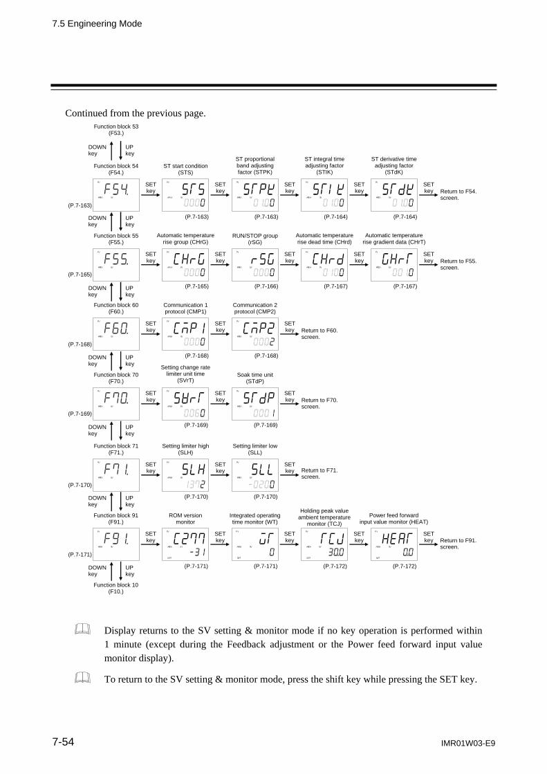
7.5 Engineering Mode
IMR01W03-E9 7-54
Continued from the previous page.
Function block 53 (F53.)
UP key
DOWN key
(P.7-163)
Holding peak value ambient temperature
monitor (TCJ)
Power feed forward input value monitor (HEAT)
ROM version monitor
Integrated operating time monitor (WT)
Function block 91 (F91.)
SET key
SET key
SET key
SET key Return to F91.
screen.
SET key
SET key
SET key
SET key Return to F54.
screen.
Function block 54 (F54.)
ST start condition (STS)
ST proportional band adjusting factor (STPK)
ST integral time adjusting factor
(STIK)
ST derivative time adjusting factor
(STdK)
UP key
DOWN key
SET key
SET key
SET key
SET key Return to F55.
screen.
Function block 55 (F55.)
Automatic temperature rise group (CHrG)
RUN/STOP group (rSG)
Automatic temperature rise dead time (CHrd)
Automatic temperature rise gradient data (CHrT)
SET key
SET key Return to F60.
screen.
Function block 60 (F60.)
Communication 1 protocol (CMP1)
Communication 2 protocol (CMP2)
UP key
DOWN key
SET key
SET key Return to F70.
screen.
Function block 70 (F70.)
Setting change rate limiter unit time
(SVrT) Soak time unit
(STdP)
UP key
DOWN key
SET key
SET key Return to F71.
screen.
Function block 71 (F71.)
Setting limiter high (SLH)
Setting limiter low(SLL)
UP key
DOWN key
UP key
DOWN key
(P.7-165)
(P.7-168)
(P.7-169)
(P.7-170)
(P.7-171)
Function block 10 (F10.)
UP key
DOWN key
SET key
SET key
SET key
SET key
SET key
SET key
(P.7-171) (P.7-171)
(P.7-169) (P.7-169)
(P.7-170) (P.7-170)
(P.7-172) (P.7-172)
(P.7-168) (P.7-168)
(P.7-163) (P.7-163) (P.7-164) (P.7-164)
(P.7-165) (P.7-166) (P.7-167) (P.7-167)
Display returns to the SV setting & monitor mode if no key operation is performed within 1 minute (except during the Feedback adjustment or the Power feed forward input value monitor display).
To return to the SV setting & monitor mode, press the shift key while pressing the SET key.
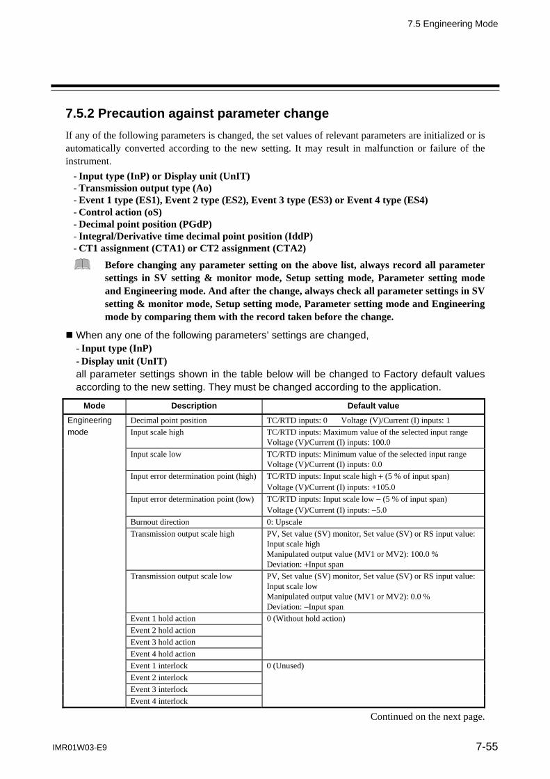
7.5 Engineering Mode
IMR01W03-E9 7-55
7.5.2 Precaution against parameter change
If any of the following parameters is changed, the set values of relevant parameters are initialized or is automatically converted according to the new setting. It may result in malfunction or failure of the instrument.
- Input type (InP) or Display unit (UnIT) - Transmission output type (Ao) - Event 1 type (ES1), Event 2 type (ES2), Event 3 type (ES3) or Event 4 type (ES4) - Control action (oS) - Decimal point position (PGdP) - Integral/Derivative time decimal point position (IddP) - CT1 assignment (CTA1) or CT2 assignment (CTA2)
Before changing any parameter setting on the above list, always record all parameter settings in SV setting & monitor mode, Setup setting mode, Parameter setting mode and Engineering mode. And after the change, always check all parameter settings in SV setting & monitor mode, Setup setting mode, Parameter setting mode and Engineering mode by comparing them with the record taken before the change.
When any one of the following parameters’ settings are changed,
- Input type (InP) - Display unit (UnIT) all parameter settings shown in the table below will be changed to Factory default values according to the new setting. They must be changed according to the application.
Mode Description Default value
Engineering Decimal point position TC/RTD inputs: 0 Voltage (V)/Current (I) inputs: 1 mode Input scale high TC/RTD inputs: Maximum value of the selected input range
Voltage (V)/Current (I) inputs: 100.0 Input scale low TC/RTD inputs: Minimum value of the selected input range
Voltage (V)/Current (I) inputs: 0.0 Input error determination point (high) TC/RTD inputs: Input scale high (5 % of input span)
Voltage (V)/Current (I) inputs: +105.0 Input error determination point (low) TC/RTD inputs: Input scale low (5 % of input span)
Voltage (V)/Current (I) inputs: 5.0 Burnout direction 0: Upscale Transmission output scale high PV, Set value (SV) monitor, Set value (SV) or RS input value:
Input scale high Manipulated output value (MV1 or MV2): 100.0 % Deviation: Input span
Transmission output scale low PV, Set value (SV) monitor, Set value (SV) or RS input value: Input scale low Manipulated output value (MV1 or MV2): 0.0 % Deviation: Input span
Event 1 hold action 0 (Without hold action) Event 2 hold action Event 3 hold action Event 4 hold action Event 1 interlock 0 (Unused) Event 2 interlock Event 3 interlock Event 4 interlock
Continued on the next page.
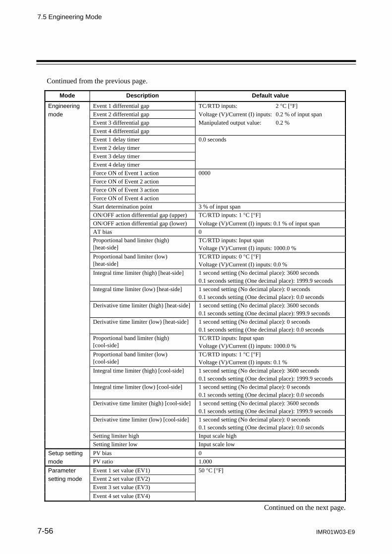
7.5 Engineering Mode
IMR01W03-E9 7-56
Continued from the previous page.
Mode Description Default value
Engineering Event 1 differential gap TC/RTD inputs: 2 C [F] mode Event 2 differential gap Voltage (V)/Current (I) inputs: 0.2 % of input span Event 3 differential gap Manipulated output value: 0.2 % Event 4 differential gap Event 1 delay timer 0.0 seconds Event 2 delay timer Event 3 delay timer Event 4 delay timer Force ON of Event 1 action 0000 Force ON of Event 2 action Force ON of Event 3 action Force ON of Event 4 action Start determination point 3 % of input span ON/OFF action differential gap (upper) TC/RTD inputs: 1 C [F] ON/OFF action differential gap (lower) Voltage (V)/Current (I) inputs: 0.1 % of input span AT bias 0 Proportional band limiter (high)
[heat-side] TC/RTD inputs: Input span Voltage (V)/Current (I) inputs: 1000.0 %
Proportional band limiter (low) [heat-side]
TC/RTD inputs: 0 C [F] Voltage (V)/Current (I) inputs: 0.0 %
Integral time limiter (high) [heat-side]
1 second setting (No decimal place): 3600 seconds 0.1 seconds setting (One decimal place): 1999.9 seconds
Integral time limiter (low) [heat-side] 1 second setting (No decimal place): 0 seconds 0.1 seconds setting (One decimal place): 0.0 seconds
Derivative time limiter (high) [heat-side]
1 second setting (No decimal place): 3600 seconds 0.1 seconds setting (One decimal place): 999.9 seconds
Derivative time limiter (low) [heat-side] 1 second setting (No decimal place): 0 seconds 0.1 seconds setting (One decimal place): 0.0 seconds
Proportional band limiter (high) [cool-side]
TC/RTD inputs: Input span Voltage (V)/Current (I) inputs: 1000.0 %
Proportional band limiter (low) [cool-side]
TC/RTD inputs: 1 C [F] Voltage (V)/Current (I) inputs: 0.1 %
Integral time limiter (high) [cool-side] 1 second setting (No decimal place): 3600 seconds 0.1 seconds setting (One decimal place): 1999.9 seconds
Integral time limiter (low) [cool-side]
1 second setting (No decimal place): 0 seconds 0.1 seconds setting (One decimal place): 0.0 seconds
Derivative time limiter (high) [cool-side]
1 second setting (No decimal place): 3600 seconds 0.1 seconds setting (One decimal place): 1999.9 seconds
Derivative time limiter (low) [cool-side]
1 second setting (No decimal place): 0 seconds 0.1 seconds setting (One decimal place): 0.0 seconds
Setting limiter high Input scale high Setting limiter low Input scale low Setup setting PV bias 0 mode PV ratio 1.000 Parameter Event 1 set value (EV1) 50 C [F] setting mode Event 2 set value (EV2) Event 3 set value (EV3) Event 4 set value (EV4)
Continued on the next page.

7.5 Engineering Mode
IMR01W03-E9 7-57
Continued from the previous page. Mode Description Default value
Parameter Control loop break alarm (LBA) time 480 seconds setting mode LBA deadband 0 Proportional band [heat-side] TC/RTD inputs: 30 C [F]
Voltage (V)/Current (I) inputs: 30.0 Integral time [heat-side] 240 seconds Derivative time [heat-side] 60 seconds Control response parameter PID control, Position proportioning PID control: 0 (Slow)
Heat/Cool PID control: 2 (Fast) Proportional band [cool-side] TC/RTD inputs: 30 C [F]
Voltage (V)/Current (I) inputs: 30.0 Integral time [cool-side] 240 seconds
Derivative time [cool-side] 60 seconds
Overlap/Deadband TC/RTD inputs: 0 C [F] Voltage (V)/Current (I) inputs: 0.0 %
Setting change rate limiter (up) oFF: Unused
Setting change rate limiter (down) oFF: Unused
SV setting & Monitor mode
Set value (SV) TC/RTD inputs: 0 C [F] Voltage (V)/Current (I) inputs: 0.0 %
When the following parameter setting is changed,
- Transmission output type (Ao) all parameter settings shown in the table below will be changed to Factory default values according to the new setting. They must be changed according to the application.
Mode Description Default value
Engineering mode
Transmission output scale high PV, Set value (SV) monitor, Set value (SV) or RS input value: Input scale high Manipulated output value (MV1 or MV2): 100.0 % Deviation: Input span
Transmission output scale low PV, Set value (SV) monitor, Set value (SV) or RS input value: Input scale low Manipulated output value (MV1 or MV2): 0.0 % Deviation: Input span
When any one of the following parameters’ setting are changed,
- Event 1 type (ES1) - Event 3 type (ES3) - Event 2 type (ES2) - Event 4 type (ES4) all parameter settings shown in the table below will be changed to Factory default values according to the new setting. They must be changed according to the application.
Mode Description Default value
Engineering Event 1 hold action 0 (Without hold action) mode Event 2 hold action Event 3 hold action Event 4 hold action
Continued on the next page.

7.5 Engineering Mode
IMR01W03-E9 7-58
Mode Description Default value
Engineering Event 1 interlock 0 (Unused) mode Event 2 interlock Event 3 interlock Event 4 interlock Event 1 differential gap TC/RTD inputs: 2 C [F] Event 2 differential gap Voltage (V)/Current (I) inputs: 0.2 % of input span Event 3 differential gap Manipulated output value: 0.2 % Event 4 differential gap Event 1 delay timer 0.0 seconds Event 2 delay timer Event 3 delay timer Event 4 delay timer Force ON of Event 1 action 0000 Force ON of Event 2 action Force ON of Event 3 action Force ON of Event 4 action Parameter Event 1 set value (EV1) 50 C [F] setting mode Event 2 set value (EV2) Event 3 set value (EV3) Event 4 set value (EV4) Control loop break alarm (LBA) time 480 seconds LBA deadband 0
When the following parameter setting is changed,
- Control action (oS) all parameter settings shown in the table below will be changed to Factory default values according to the new setting. They must be changed according to the application.
Mode Description Default value
Engineering mode
Undershoot suppression factor PID control (direct action): 1.000 PID control (reverse action): 1.000 Heat/Cool PID control [water cooling]: 0.100 Heat/Cool PID control [air cooling]: 0.250 Heat/Cool PID control [Cooling gain linear type]: 1.000 Position proportioning PID control (reverse action): 1.000 Position proportioning PID control (direct action): 1.000
Parameter setting mode
Control response parameter PID control, Position proportioning PID control: 0 (Slow) Heat/Cool PID control: 2 (Fast)

7.5 Engineering Mode
IMR01W03-E9 7-59
When the following parameter setting is changed, - Decimal point position (PGdP) all parameter settings shown in the table below will be automatically converted into the a values to match the new decimal point position as long as the converted values are in the acceptable range of each parameter. They must be check and changed if necessary according to the application.
Mode Description
Engineering mode Input scale high Input scale low Input error determination point (high) Input error determination point (low) Transmission output scale high 1 Transmission output scale low 1 Event 1 differential gap 2 Event 2 differential gap 2 Event 3 differential gap 2 Event 4 differential gap 2 Start determination point ON/OFF action differential gap (upper) 3 ON/OFF action differential gap (lower) 3 AT bias Proportional band limiter (high) [heat-side] 3 Proportional band limiter (low) [heat-side] 3 Proportional band limiter (high) [cool-side] 3 Proportional band limiter (low) [cool-side] 3 Setting limiter high Setting limiter low Setup setting mode PV bias RS bias Parameter setting mode Event 1 set value (EV1) 2 Event 2 set value (EV2) 2 Event 3 set value (EV3) 2 Event 4 set value (EV4) 2 LBA deadband Proportional band [heat-side] 3 Proportional band [cool-side] 3 Overlap/Deadband 3 Setting change rate limiter (up) Setting change rate limiter (down) SV setting & Monitor mode Measured value (PV) Set value (SV) monitor Set value (SV) Remote setting (RS) input value
1 Only for Measured value (PV), Set value (SV) monitor, Set value (SV) or Remote setting (RS) input value 2 Only for deviation, input value or set value 3 Only for thermocouple (TC) or RTD inputs

7.5 Engineering Mode
IMR01W03-E9 7-60
Precaution and Example of automatic conversion
Decimal point position moves in accordance with the setting change. Example: When the setting of the Decimal point position is changed from 0 (no decimal place)
to 1 (one decimal place) with Input scale high (PGSH) set to 800 °C:
(PGSH) (PGSH)
(Changed from 800 to 800.0)
The display will change from 800 to 800.0. If the position of the decimal point is set to any digit exceeding the input range, limited the
maximum or minimum value of each input type. Example: When RTD input is selected for Input type (InP), and Input scale low (PGSL) is
200 C, the Decimal point position is changed from 1 to 2:
(PGSL) (PGSL) Input scale low becomes the minimum value of the selected input range, because -200.00 is out of the display range.
Input type Range
100.00 to +100.00 C Pt100
200.0 to +850.0 C
Maximum value or minimum value of the selected input range
When a number of decimal places for the set value is reduced due to the decimal point change, the
set value is rounded off to the first decimal place and will be displayed without any decimal place. Example: When the Decimal point position is changed from 1 (one decimal places) to
0 (no decimal place) and Input scale high (PGSH) is 849.9:
(PGSH) (PGSH)
The figure is rounded off to the first decimal place, and the Input scale high PGSH becomes 850.

7.5 Engineering Mode
IMR01W03-E9 7-61
When the following parameter setting is changed, - Integral/Derivative time decimal point position (IddP) all parameter settings shown in the table below will be automatically converted into the a values to match the new decimal point position as long as the converted values are in the acceptable range of each parameter. They must be check and changed if necessary according to the application.
Mode Description
Engineering mode Integral time limiter (high) [heat-side] Integral time limiter (low) [heat-side] Derivative time limiter (high) [heat-side] Derivative time limiter (low) [heat-side] Integral time limiter (high) [cool-side] Integral time limiter (low) [cool-side] Derivative time limiter (high) [cool-side] Derivative time limiter (low) [cool-side] Parameter setting mode Integral time [heat-side] Derivative time [heat-side] Integral time [cool-side] Derivative time [cool-side]

7.5 Engineering Mode
IMR01W03-E9 7-62
7.5.3 Engineering setting item
Function block 10 (F10.)
This is the first parameter symbol of Function block 10 (F10.).
F10.
STOP display
STOP message for control STOP mode can be displayed either on the upper display or the lower display. SPCH is to select the display to show the STOP message.
Data range Factory set value
0: Displays on the Measured value (PV) unit 1: Displays on the Set value (SV) unit
1
Description of function
There are four different Characters for STOP mode depending on how to be transferred from RUN to STOP.
(KSTP) (dSTP) (SToP)
(KSTP) (dSTP) (SToP)
The SToP is displayed on the PV display.
(GSTP)
(GSTP)
The SToP is displayed on the SV display.
When the control was stopped, the Measured value (PV) can be checked.
When the control was stopped, the Set value (SV) can be checked.
For the differences in the STOP (control stop) state, refer to 6.14.3 Group RUN/STOP function (P. 6-63).

7.5 Engineering Mode
IMR01W03-E9 7-63
F10.
Bar graph display CT
input
OPTION
Use to select the contents of the bar graph display.
Data range Factory set value
0: No display 1: Manipulated output value (MV) 2: Measured value (PV) 3: Set value (SV) monitor 4: Deviation value 5: Current transformer 1 (CT1) input value 6: Current transformer 2 (CT2) input value
1
Number of display dots FB400: 10 dots FB900: 20 dots
Related parameter Engineering mode: Bar graph display resolution (P. 7-65)
Description of function
Bar graph display explanation: (1) Manipulated output value (MV) Displays the Manipulated output value (MV). When Manipulated output value (MV) is at 0 % or less, the left-end dot of the bar-graph flashes. When MV exceeds 100 %, the right-end dot flashes. [Display example]] 0 % 50 % 100 %
When the control action is the Heat/Cool PID control: When both of ‘OUT1’ and ‘OUT2’ are lit (when overlapped), the bar graph displays the Manipulated output value (MV1) [heat-side].
When the control action is the Position proportioning PID control: [With FBR input]
Displays the FBR input value (0.0 to 100.0 %). [Without FBR input]
Cannot be used as a bar graph. The bar graph displays the over-scaled state (an output of more then 100 %).
[Display example] 0 % 50 % 100 %
the left-end dot of the bar-graph flashes.
In this case, it is recommended to be set to “0: No display.”

7.5 Engineering Mode
IMR01W03-E9 7-64
(2) Measured value (PV) Displays the Measured value (PV). Scaling is available within the input range.
[Display example]] 0 50 100
(3) Set value (SV) monitor Displays the Set value (SV). Scaling is available within the input range. Displays the remote set value when the Operation mode is remote mode.
[Display example]] 0 C 50 C 100 C
(4) Deviation value Displays the deviation between the Measured value (PV) and the Set value (SV). When the Deviation display is selected, the dots at both ends of bar-graph light. A display resolution per dot is settable from 1 to 100. The display resolution can be set in the Bar graph display resolution (dEUT). (Refer to P. 7-65)
[Display example]] +0
(5) Current transformer 1 (CT1) input value or Current transformer 2 (CT2) input value Displays the input value (current value) of CT1 or CT2. A display resolution per dot is settable from 1 to 100. The display resolution can be set in the Bar graph display resolution (dEUT). (Refer to P. 7-65)
[Display example]] 0.0 A 15.0 A 30.0 A

7.5 Engineering Mode
IMR01W03-E9 7-65
F10.
Bar graph display resolution CT
input
OPTION
Use to set the bar graph display resolution for the deviation, Current transformer 1 (CT1) or Current transformer 2 (CT2) display. Set several digits per 1 dot of the bar graph.
Data range Factory set value
1 to 100 digit/dot 100
Related parameter Engineering mode: Bar graph display (P. 7-63)
Display resolution setting example of Deviation value
Condition: Controller: FB900 Bar graph display resolution setting: 10 digit/dot
When the input range is the 1 C [F] unit When the input range is the 0.1 C [F] unit
0 0
Display becomes 10 C[F]/dot. Display becomes 1.0 C[F]/dot.
Display resolution setting example of CT1
Condition: Current transformer type: CTL-6-P-N (0.0 to 30.0 A) Controller: FB900 Bar graph display resolution setting: 100 digit/dot
0.0 A 15.0 A 30.0 A
Display becomes 1.5 A/dot.
Bar graph display range becomes 0.0 to 30.0 A.
Display resolution and Bar graph display range
Current Bar graph resolution setting
transformer type 1 digit/dot 10 digit/dot 100 digit/dot
CTL-6-P-N (0.0 to 30.0 A)
Per 1 dot: FB400: 0.03 A/dot FB900: 0.015 A/dot
Per 1 dot: FB400: 0.3 A/dot FB900: 0.15 A/dot
Per 1 dot: FB400: 3.0 A/dot FB900: 1.5 A/dot
Bar graph display range: 0.0 to 0.3 A
Bar graph display range: 0.0 to 3.0 A
Bar graph display range: 0.0 to 30.0 A
CTL-12-S56-10L-N (0.0 to 100.0 A)
FB400: 0.1 A/dot FB900: 0.05 A/dot
FB400: 1.0 A/dot FB900: 0.5 A/dot
FB400: 10.0 A/dot FB900: 5.0 A/dot
Bar graph display range: 0.0 to 1.0 A
Bar graph display range: 0.0 to 10.0 A
Bar graph display range: 0.0 to 100.0 A

7.5 Engineering Mode
IMR01W03-E9 7-66
F10.
PV flashing display at input error
It can be so set that the PV display does not flash if not required. The Measured value (PV) of this instrument flashes in the range of an “5 % of input span” if exceeding the input range.
Data range Factory set value
0: Flashing display 1: Non-flashing display
0
Example: When set to non-flashing display in the range of 200.0 to 800.0 C
Input range
(Input scale low to Input scale high)
5 of input span (50 C) Non-flashing display
Display range limit (Non-flashing display)
Underscale flashing display
Over-scale flashing display
250.0 C 200.0 C 800.0 C 850.0 C
Input span: 1000 C
However, if the Input error determination point (low) or the Input error determination point (high) is set within the input range, up to ±5 % of input span from the Input error determination point (low) or (high) becomes the PV flashing display range.

7.5 Engineering Mode
IMR01W03-E9 7-67
Function block 11 (F11.)
This is the first parameter symbol of Function block 11 (F11.)
F11.
Direct key 1
Use to select Use/Unuse of Direct key 1. The Direct key 1 can be used as an A/M transfer key.
Data range Factory set value
0: Unused 1: A/M transfer key
1
Related parameter Engineering mode: Direct key type (P. 7-68)
F11.
Direct key 2
Use to select Use/Unuse of Direct key 2. The usage of Direct key 2 is different depending on the Direct key type (Fn). When the Direct key type (Fn) is the Type 1: MONI key When the Direct key type (Fn) is the Type 2: R/L transfer key
Data range Factory set value
0: Unused 1: MONI key (For Type 1) or
R/L transfer key (For Type 2)
1
Related parameter Engineering mode: Direct key type (P. 7-68)

7.5 Engineering Mode
IMR01W03-E9 7-68
F11.
Direct key 3
Use to select Use/Unuse of Direct key 3. The usage of Direct key 3 is different depending on the Direct key type (Fn). When the Direct key type (Fn) is the Type 1: AREA key When the Direct key type (Fn) is the Type 2: R/S transfer key
Data range Factory set value
0: Unused 1: AREA key (For Type 1) or
R/S transfer key (For Type 2)
1
Related parameter Engineering mode: Direct key type (P. 7-68)
F11.
Direct key type
Use to select the type of direct key.
Data range Factory set value
1: Type 1 2: Type 2
1
Content of Type 1 or 2
Direct key type Direct key1 Direct key2 Direct key3
Type 1 A/M transfer key MONI key AREA key
Type 2 A/M transfer key R/L transfer key R/S transfer key
A/M: Auto/Manual R/L: Remote/Local R/S: RUN/STOP
Related parameters Engineering mode: Direct key 1 (P. 7-67) Direct key 2 (P. 7-67) Direct key 3 (P. 7-68)

7.5 Engineering Mode
IMR01W03-E9 7-69
Function block 21 (F21.)
This is the first parameter symbol of Function block 21 (F21.).
F21.
Input type
Data range: 0 to 26 (refer to the following table) A measured input is a universal input but requires hardware selection (of a Voltage (low) or (high) input group). The input select switch enables hardware selection. (Refer to next page.)
Data range Hardware Factory set value
0: TC input K 1: TC input J 2: TC input R 3: TC input S 4: TC input B 5: TC input E 6: TC input N 7: TC input T 8: TC input W5Re/W26Re 9: TC input PLII 10: TC input U 11: TC input L 12: RTD input Pt100 13: RTD input JPt100 14: Current input 0 to 20 mA DC 15: Current input 4 to 20 mA DC 19: Voltage (low) input 0 to 1 V DC 20: Voltage (low) input 0 to 100 mV DC 21: Voltage (low) input 0 to 10 mV DC 25: Voltage (low) input 100 mV DC 26: Voltage (low) input 10 mV DC
Voltage (low) input group
If no input range code is specified: 0 If the input type is specified by the model and suffix code when ordering, that input type becomes the factory set value.
16: Voltage (high) input 0 to 10 V DC 17: Voltage (high) input 0 to 5 V DC 18: Voltage (high) input 1 to 5 V DC 24: Voltage (high) input 1 V DC
Voltage (high) input group
Do not set to any number (including 22 and 23) which is not described in the input range table above. This may cause malfunctioning.
Continued on the next page.

7.5 Engineering Mode
IMR01W03-E9 7-70
Continued from the previous page.
As the Decimal point position, Input scale high and Input scale low are initialized if the input type is changed, it is necessary to conduct the re-setting. A value of “3 % of input span” is automatically set at the Start determination point. For the parameters which will be initialized if the input type is changed, refer to 7.5.2 Precaution against parameter change (P. 7-55).
Related parameters Engineering mode: Display unit (P. 7-71) Decimal point position (P. 7-71) Input scale high, Input scale low (P. 7-72)
Hardware selection
The Voltage (low) or (high) input group is selected by the input select switch (for Measured input) at the side of the instrument. Turn the Measured input switch by a small screwdriver.
Input select switch
Voltage (low) input group
For the Measured input
Voltage (high) input group
For Remote setting (RS) input

7.5 Engineering Mode
IMR01W03-E9 7-71
F21.
Display unit
Use to select the temperature unit for Thermocouple (TC) and RTD inputs.
Data range Factory set value
0: C 1: F
If no input range code is specified: 0 If the Display unit type is specified by the model and suffix code when ordering, that Display unit becomes the factory set value.
The invalidity in case of the Voltage/Current inputs.
F21.
Decimal point position
Use to select the Decimal point position of the input range.
Data range Factory set value
0: No decimal place 1: One decimal place 2: Two decimal places 3: Three decimal places 4: Four decimal places TC input: K, J, E: Only 0 or 1 can be set. T, U, L: Only 1 can be set. Other than the above: Only 0 can be set. RTD input: From 0 to 2 can be set. Voltage (V)/Current (I) inputs: From 0 to 4 can be set.
If no input range code is specified: 0 If the Decimal point position is specified by the model and suffix code when ordering, that Decimal point position becomes the factory set value.
Related parameters Engineering mode: Input type (P. 7-69) Input scale high, Input scale low (P. 7-72)

7.5 Engineering Mode
IMR01W03-E9 7-72
F21.
Input scale high Input scale low
Use to set the high limit and low limit of the input scale range.
Data range Factory set value
Input scale high TC/RTD inputs: Input scale low to Maximum value of the selected input range Varies with the setting of the Decimal point position (P. 7-71).
Maximum value of the selected input
range
Voltage (V)/Current (I) inputs:19999 to 19999 Varies with the setting of the Decimal point position (P. 7-71).
100.0
Input scale low TC/RTD inputs: Minimum value of the selected input range to Input scale high Varies with the setting of the Decimal point position (P. 7-71).
Minimum value of the selected input
range
Voltage (V)/Current (I) inputs:19999 to 19999 Varies with the setting of the Decimal point position (P. 7-71).
0.0
When a Voltage (V)/Current (I) input type is selected, the input scale high limit can be set lower than the input scale low limit. (Input scale high limit < Input scale low limit)
Related parameters Engineering mode: Input type (P. 7-69) Decimal point position (P. 7-71)
Description of function The input range can be changed for temperature input (TC/RTD). For Voltage (V)/Current (I) input, display scaling can be made in the range of 19999 to 19999.
Example (temperature input): When the range of 200.0 to +800.0 C for Thermocouple Type K is changed to 0.0 to 400.0 C
Maximum value of the
selected input range +800.0 C
Input range
Input scale low 0.0 C Input scale high 400.0 C
Input span 400.0 C
Input span 1000.0 C
Minimum value of the selected input range
200.0 C
When the scale for temperature input is changed, it is recommended to be changed within the input range. If any value exceeding the input range is set, input resolution may vary.
If the Input scale high or low limit is changed, a value of “3 % of input span” is automatically set at the Start determination point.

7.5 Engineering Mode
IMR01W03-E9 7-73
Example [Voltage (V)/Current (I) inputs]: When the input scale is changed to “0.0 to 50.0” from “0.0 to 100.0” at a voltage input of 1 to 5 V DC
Input scale low 0.0
Voltage input 1 V
Input scale high 100.0
Voltage input 5 V
Input scale low 0.0
Voltage input 1 V
Input scale high50.0
Voltage input 5 V
Scale change
Table 1: Input range table
Input type Data range Hardware
TC input K 200.0 to 400.0 C 328.0 to +400.0 F 200.0 to 800.0 C 250.0 to +800.0 F 200 to 1372 C 328 to +2502 F J 0.0 to 400.0 C 200.0 to 700.0 F 200.0 to 400.0 C 328.0 to +1200 F 200.0 to 800.0 C 328 to +2192 F 200 to 1200 C T 200.0 to 400.0 C 328.0 to +752.0 F S 50 to 1768 C 58 to 3214 F R 50 to 1768 C 58 to 3214 F E 200.0 to 700.0 C 328.0 to +1292.0 F 200 to 1000 C 328 to +1832 F B 0 to 1800 C 0 to 3272 F N 0 to 1300 C 0 to 2372 F Voltage (low) PLII 0 to 1390 C 0 to 2534 F input group W5Re/W26Re 0 to 2300 C 0 to 4200 F U 0.0 to 600.0 C 32.0 to 1112.0 F L 0.0 to 900.0 C 32.0 to 1652.0 F RTD input Pt100 100.00 to 100.00 C 199.99 to +199.99 F 200.0 to 850.0 C 328.0 to +1562.0 F JPt100 100.00 to 100.00 C 199.99 to +199.99 F 200.0 to 640.0 C 328.0 to +1184.0 F Current input 0 to 20 mA DC 4 to 20 mA DC Voltage (low) 0 to 1 V DC input 0 to 100 mV DC Programmable range 0 to 10 mV DC 19999 to 19999 100 mV DC (The decimal point position of the input range is selectable.) 10 mV DC Voltage (high) 0 to 10 V DC input 0 to 5 V DC Voltage (high) 1 to 5 V DC input group 1 V DC

7.5 Engineering Mode
IMR01W03-E9 7-74
F21.
Input error determination point (high) Input error determination point (low)
If the Measured value (PV) is above the Input error determination point (high) or below the Input error determination point (low), Action (high) at input error or Action (low) at input error will be taken.
Data range Factory set value
Input error determination point (high) Input scale low (5 % of input span) to Input scale high + (5 % of input span) Varies with the setting of the Decimal point position (P. 7-71).
TC/RTD inputs: Input scale high + (5 % of input span) Voltage (V)/Current (I) inputs: 105.0
Input error determination point (low) Input scale low (5 % of input span) to Input scale high + (5 % of input span) Varies with the setting of the Decimal point position (P. 7-71).
TC/RTD inputs: Input scale low (5 % of input span) Voltage (V)/Current (I) inputs: 5.0
Related parameters Engineering mode: Decimal point position (P. 7-71) Action (high) at input error, Action (low) at input error (P. 7-135) Manipulated output value at input error (P. 7-136)
Example: When the input scale range is 200 to 1372 C
Input span: 1572 5 % of input span: 79 (78.6 was rounded off) Setting range: 279 to +1451 C
200 C
5 % of input span (79 C)
5 % of input span (79 C) Input span 1572 C
279 C +1372 C +1451 C Input range
Input scale low Input scale high
Setting range of the input error determination point

7.5 Engineering Mode
IMR01W03-E9 7-75
F21.
Burnout direction
Use to select Burnout direction in input break. When input break is detected by the controller, the measured value go either Upscale or Downscale according to the Burnout direction setting.
Data range Factory set value
0: Upscale 1: Downscale
0
The Burnout direction setting are effective only for Thermocouple input and Voltage (low) input.
For the following types of input, the action when an input break occurs is fixed, regardless of the Burnout direction setting.
RTD input: Upscale Voltage (high) input: Downscale (display of about 0 V) Current input: Downscale (display of about 0 mA)
F21.
Square root extraction
Use to select Use/Unuse of the Square root extraction for the measured value.
Data range Factory set value
0: Unused 1: Used
0
Related parameter Setup setting mode: PV low input cut-off (P. 7-41)
Description of function
The controller can receive the input signal directly from a differential pressure type flow transmitter by using Square root extraction function without using a square root extractor.

7.5 Engineering Mode
IMR01W03-E9 7-76
F21.
Power supply frequency
Use to select the Power supply frequency of the controller suited to the application. If the display on the screen flickers, set the value to the same value as the power frequency used.
Data range Factory set value
0: 50 Hz 1: 60 Hz
0
No power frequency can be changed while if can be normally measured with the Current transformer (CT) input and/or Power feed forward (PFF) input provided.
F21.
Sampling cycle
This is a sampling time when measured input is captured.
Data range Factory set value
0: 50 ms 1: 100 ms 2: 250 ms
1

7.5 Engineering Mode
IMR01W03-E9 7-77
Function block 22 (F22.)
This is the first parameter symbol of Function block 22 (F22.).
F22.
Remote setting input type
Data range: 14 to 21 (refer to the following table) Remote setting (RS) input requires hardware selection (of a Voltage (low) or (high) input group). The input select switch enables hardware selection.
Data range Hardware Factory set value
14: Current input 0 to 20 mA DC 15: Current input 4 to 20 mA DC
Voltage (low) input group
If no Remote setting input type is specified: 15
If the Remote setting input type is specified by model and suffix code when ordering, that Remote setting input type becomes the factory set value.
16: Voltage input 0 to 10 V DC 17: Voltage input 0 to 5 V DC 18: Voltage input 1 to 5 V DC
Voltage (high)input group
19: Voltage input 0 to 1 V DC 20: Voltage input 0 to 100 mV DC21: Voltage input 0 to 10 mV DC
Voltage (low) input group
Hardware selection
The Voltage (low) or (high) input group is selected by the input select switch (for Remote setting (RS) input) at the side of the instrument. Turn the Remote setting (RS) input switch by a small screwdriver.
Input select switch
Voltage (low) input group
For the Measured input
Voltage (high) input group
For Remote setting (RS) input

7.5 Engineering Mode
IMR01W03-E9 7-78
Function block 23 (F23.)
This is the first parameter symbol of Function block 23 (F23.).
F23.
Digital input (DI) assignment
Use to assign the function (Memory area, Operation mode) for the Digital inputs (DI 1 to DI 7).
Data range Factory set value
1 to 8 (For details, refer to the following table.)
1
Table 1 Digital input (DI) assignment
Set DI1 DI2 DI3 DI4 DI5 DI6 DI7
value Terminal No.30-31
Terminal No.30-32
Terminal No.30-33
Terminal No.30-34
Terminal No.13-14
Terminal No.13-15
Terminal No.13-16
1 Memory area number transfer (1 to 8) Memory area set *
Unused
Unused Unused
2 Memory area number transfer (1 to 8) Memory area set *
RUN/STOP transfer
Remote/Local transfer
Auto/Manual transfer
3 Memory area number transfer (1 to 8) Memory area set *
RUN/STOP transfer
Remote/Local transfer
Interlock release
4 Memory area number transfer (1 to 8) Memory area set *
RUN/STOP transfer
Auto/Manual transfer
Interlock release
5 Memory area number transfer (1 to 8) Memory area set *
Remote/Localtransfer
Auto/Manual transfer
Interlock release
6 Memory area number transfer (1 to 8) Memory area set *
RUN/STOP transfer
Unused Interlock release
7 Memory area number transfer (1 to 8) Memory area set *
Remote/Localtransfer
Unused Interlock release
8 Memory area number transfer (1 to 8) Memory area set *
Auto/Manual transfer
Unused Interlock release
* Only when ZK-1165 specification was specified, memory area transfer is possible without area set input. For memory area transfer by ZK-1165 specification, refer to ZK-1165 Specification (IMR01W08-E).
For Digital input (DI) transfer, refer to following page. Memory area number transfer: Refer to 6.9 Control Area Transfer (P. 6-32). RUN/STOP transfer: Refer to 6.4 RUN/STOP Transfer (P. 6-11). Remote/Local transfer: Refer to 6.8 Remote/Local Transfer (P. 6-28). Auto/Manual transfer: Refer to 6.7 Auto/Manual Transfer (P. 6-23). Interlock release: Refer to 6.10 Interlock Release (P. 6-36).

7.5 Engineering Mode
IMR01W03-E9 7-79
Function block 30 (F30.)
This is the first parameter symbol of Function block 30 (F30.).
F30.
Output assignment Digital
output
OPTION
This is used to assign the Output function (Control output, Event output, etc.) for the Output (OUT1 and OUT2) and the Digital output (DO1 to DO4).
Data range Factory set value
1 to 7 (For details, refer to table 1.)
2 If an Output assignment is specified when the order is placed, the factory set value will be the specified value.
Related parameters Engineering mode: Energized/De-energized (P. 7-80) Alarm (ALM) lamp lighting condition 1 (P. 7-81) Alarm (ALM) lamp lighting condition 2 (P. 7-81) Event 1 type (P. 7-85) Event 3 type (P. 7-102) Event 2 type (P. 7-95) Event 4 type (P. 7-109) CT1 assignment (P. 7-117) CT2 assignment (P. 7-121)
Table 1: Output assignment
Set value OUT1 OUT2 DO1 DO2 DO3 DO4
1 MV1 MV2 EV1 EV2 EV3 EV4 2 MV1 MV2 EV1 EV2 EV3 HBA1, HBA23 MV1 MV2 EV1 EV2 HBA1, HBA2 FAIL 4 MV1 MV2 EV1 HBA1, HBA2 EV3 EV4 5 MV1 HBA1, HBA2 EV1 EV2 EV3 EV4 6 MV1 HBA1, HBA2 EV1 EV2 EV3 FAIL 7 MV1 FAIL EV1 EV2 EV3 EV4
MV1: Manipulated output (control output) [heat-side] EV1: Event 1 EV3: Event 3 HBA1: Heater break alarm 1 FAIL: FAIL output MV2: Manipulated output (control output) [cool-side] EV2: Event 2 EV4: Event 4 HBA2: Heater break alarm 2
“Energized” or “De-energized” of DO1 to DO4 can be changed in Engineering mode.
Only “De-energized” is available for the FAIL output. No “Energized” is available.
An output logic becomes OR output when two or more Output functions are assigned to one output.
To use for Heat/Cool PID control or Position proportioning PID control, select a set value from 1 to 4.
Outputs and Event functions not specified in the model code is not valid if specified.

7.5 Engineering Mode
IMR01W03-E9 7-80
F30.
Timer 1 Timer 3 Timer 2 Timer 4
The customization tool is required for using the Timer 1 to 4 function. As this function cannot be used at present, do not change it.
Data range Factory set value
0.0 to 600.0 seconds 0.0 F30.
Energized/De-energized Digital
output
OPTION
Use to select the Energized or De-energized for the Digital output 1 to 4 (DO1 to DO4). However, the FAIL alarm is fixed to De-energized. (When at FAIL alarm occurrence: Contact opened)
DO1: 0: Energized 1: De-energized DO2: 0: Energized 1: De-energized DO3: 0: Energized 1: De-energized DO4: 0: Energized 1: De-energized
Factory set value: 0000 (energized)
Related parameters Engineering mode: Output assignment (P. 7-79) Event 3 type (P. 7-102) Event 1 type (P. 7-85) Event 4 type (P. 7-109) Event 2 type (P. 7-95)
Description of function
Energized: Relay contact is closed under the event or alarm status. De-energized: Relay contact opens under the event or alarm status.
Diagram for explaining operation (At power-ON)
Energized
Non-event status Event status
De- energized
Non-event status Event status

7.5 Engineering Mode
IMR01W03-E9 7-81
F30.
Alarm (ALM) lamp lighting condition 1 Alarm (ALM) lamp lighting condition 2
CT input
OPTION
Use to set an alarm (ALM) lamp lighting conditions to Event 1 to Event 4, HBA1 and HBA2. The alarm lamp is lit through the OR operation of Event 1 to Event 4, HBA1 and HBA2 each of which is set to “1: ALM lamp is lit.”
Event 1 (EV1): 0: ALM lamp is not lit 1: ALM lamp is lit Event 2 (EV2): 0: ALM lamp is not lit 1: ALM lamp is lit Event 3 (EV3): 0: ALM lamp is not lit 1: ALM lamp is lit Event 4 (EV4): 0: ALM lamp is not lit 1: ALM lamp is lit
Factory set value: 1111 (ALM lamp is lit)
Heater break alarm 1 (HBA1): 0: ALM lamp is not lit 1: ALM lamp is lit
Heater break alarm 2 (HBA2): 0: ALM lamp is not lit 1: ALM lamp is lit
“0” fixed (No setting) “0” fixed (No setting)
Factory set value: 0011 (ALM lamp is lit)
Related parameters Engineering mode: Output assignment (P. 7-79) Event 1 type (P. 7-85) Event 2 type (P. 7-95) Event 3 type (P. 7-102) Event 4 type (P. 7-109) CT1 assignment (P. 7-117) CT2 assignment (P. 7-121)

7.5 Engineering Mode
IMR01W03-E9 7-82
F30.
Output status at STOP mode
It is selected whether or not Event output, Heater break alarm output or Transmission output is continued or turned off when the controller is set to STOP (control stop).
Event output, Heater break alarm (HBA) output:
0: OFF 1: Action continued
Transmission output:
0: OFF 1: Action continued
“0” fixed (No setting)
“0” fixed (No setting)
Factory set value: 0000
Related parameters Engineering mode: Output assignment (P. 7-79) Transmission output type (P. 7-83) Event 1 type (P. 7-85) Event 2 type (P. 7-95) Event 3 type (P. 7-102) Event 4 type (P. 7-109) CT1 assignment (P. 7-117) CT2 assignment (P. 7-121)

7.5 Engineering Mode
IMR01W03-E9 7-83
Function block 33 (F33.)
This is the first parameter symbol of Function block 33 (F33.).
F33.
Transmission output type AO
OPTION
Use to select the transmission output type.
Data range Factory set value
0: None 1: Measured value (PV) 2: Set value (SV) monitor 3: Deviation value 4: Manipulated output value (MV1) [heat-side] * 5: Manipulated output value (MV2) [cool-side] 6: Set value (SV) 7: Remote setting (RS) input value
1
* For Position proportioning PID control: Feedback resistance input value
Related parameters Engineering mode: Output status at STOP mode (P. 7-82) Transmission output scale high (P. 7-84) Transmission output scale low (P. 7-84)
Description of function
The Transmission output (analog output) is the function of outputting the state of Measured value (PV), Set value (SV), Deviation value, Manipulated output value or Remote setting (RS) input value as a Voltage or Current signal. It is possible to record the state of Measured value (PV) or Set value (SV) when connected to a recorder. Output types of transmission output:
Voltage output 0 to 1 V DC, 0 to 5 V DC, 0 to 10 V DC, 1 to 5 V DC
Current output 0 to 20 mA DC, 4 to 20 mA DC

7.5 Engineering Mode
IMR01W03-E9 7-84
F33.
Transmission output scale high Transmission output scale low
AO
OPTION
Use to set a scale high limit value or low limit value of the Transmission output.
Data range Factory set value
When the transmission type is the Measured value (PV), Set value (SV) monitor, Set value (SV) or Remote setting (RS) input value:
Input scale low to Input scale high Varies with the setting of the Decimal point position (P. 7-71).
Transmission output scale high: Input scale high Transmission output scale low: Input scale low
When the transmission type is the deviation value: Input span to +Input span
When the transmission type is the Manipulated output value (MV1) or Manipulated output value (MV2): 5.0 to +105.0 %
The Decimal point position is the same as Decimal point position (PGdP) of the input.
Related parameters Engineering mode: Decimal point position (P. 7-71) Output status at STOP mode (P. 7-82) Transmission output type (P. 7-83)
Description of function
This is the function of scaling the output range for the content of transmission selected by the Transmission output type (Ao). Example: If scaling is made under the following conditions
Output signal type: Current output 4 to 20 mA DC Transmission output type (Ao): Measured value (PV) Transmission output scale high (AHS): +1372 C Transmission output scale low (ALS): 200 C
Current output
Measured value (PV)
20 mA4 mA
200 C
+1372 C

7.5 Engineering Mode
IMR01W03-E6 7-85
Function block 41 (F41.)
This is the first parameter symbol of Function block 41 (F41.).
F41.
Event 1 type
Use to select a action type of the Event 1.
Data range Factory set value
0: None 0 If the event type is specified by the model and suffix code when ordering, that event type becomes the factory set value.
Deviation action: 1: Deviation high 1
2: Deviation low 1
3: Deviation high/low 1
4: Band 1 Input value action: 5: Process high 1
6: Process low 1 Set value action: 7: Set value (SV) high 8: Set value (SV) low Manipulated output value action: 10: Manipulated output value (MV1) high
[heat-side] 1, 2 11: Manipulated output value (MV1) low
[heat-side] 1, 2 12: Manipulated output value (MV2) high
[cool-side] 1 13: Manipulated output value (MV2) low
[cool-side] 1
9: Unused Do not set to “9: Unused” for Event 1.
1 Event hold action is available. 2 The Manipulated output value (MV) corresponds to the Feedback resistance (FBR)
input value when Feedback resistance (FBR) input is used.
Related parameters Parameter setting mode: Event 1 set value (P. 7-21)
Continued on the next page.

7.5 Engineering Mode
IMR01W03-E9 7-86
Continued from the previous page.
Engineering mode: Output assignment (P. 7-79) Energized/De-energized (P. 7-80) Alarm (ALM) lamp lighting condition 1 (P. 7-81) Output status at STOP mode (P. 7-82) Event 1 hold action (P. 7-87) Event 1 interlock (P. 7-89) Event 1 differential gap (P. 7-90) Event 1 delay timer (P. 7-91) Force ON of Event 1 action (P. 7-93)
Description of function
Diagrams of the event action type are shown in the following. ON: Event action turned on OFF: Event action turned off
1: Deviation high (using SV monitor value)
(Event set value is greater than 0.) (Event set value is less than 0.)
2: Deviation low (using SV monitor value)
(Event set value is greater than 0.) (Event set value is less than 0.)
5: Process high 6: Process low
7: SV high: 8: SV low:
10: MV high [heat-side] 12: MV high [cool-side]
11: MV low [heat-side] 13: MV low [cool-side]
( : Set value (SV) : Event set value ☆: Event differential gap)
3: Deviation high/low (using SV monitor value) 4: Band (using SV monitor value)
Deviation action: If the Deviation (PV – SV) reaches the Event set value, Event ON occurs.
Input value action: When the Measured value (PV) reaches the Event set value, Event ON occurs.
Set value action: When the Set value (SV) reaches the Event set value, Event ON occurs.
Manipulated output value action: When the Manipulated output value (MV) reaches the Event set value, Event ON occurs.
OFF ON PV
Low High
☆OFF ON Low High
PV☆
ON OFF PV
Low High
☆ ON OFF PV
Low High
☆
OFF ON OFF PV
Low High
☆ ☆ ON OFF ON PV
Low High
☆ ☆
ON OFF PV
Low High
☆OFF ON PV
Low High
☆
ON OFF SV
Low High
☆OFF ON SV
Low High
☆
ON OFF MV
Low High
☆OFF ON MV
Low High
☆

7.5 Engineering Mode
IMR01W03-E9 7-87
F41.
Event 1 hold action
Use to set an Event hold action for the Event 1.
Data range Factory set value
0: OFF
1: Hold action ON (Only Hold action) Validate the Hold action when the power is
turned on. Validate the Hold action when transferred from
STOP (control STOP) to RUN (control RUN).
2: Re-hold action ON (Hold and Re-hold actions) Validate the Hold action when the power is
turned on. Validate the Hold action when transferred from
STOP (control STOP) to RUN (control RUN). Validate the Re-hold action when the Set value
(SV) is changed. However, if the rate of setting change limiter is set to any function other than “OFF (Unused)” or in the Remote mode, the Re-hold action becomes invalid.
0
If the event type is specified by the model and suffix code when ordering, the factory set value of Event 1 hold action differs depending on that event type.
When high alarm with Hold/Re-hold action is used for Event function, alarm does not turn on while Hold action is in operation. Use in combination with a high alarm without Hold action in order to prevent overheating which may occur by failure of control devices, such as welding of relays.
Related parameters Parameter setting mode: Event 1 set value (P. 7-21)
Engineering mode: Energized/De-energized (P. 7-80) Alarm (ALM) lamp lighting condition 1 (P. 7-81) Output status at STOP mode (P. 7-82) Event 1 type (P. 7-85) Event 1 interlock (P. 7-89) Event 1 differential gap (P. 7-90) Event 1 delay timer (P. 7-91) Force ON of Event 1 action (P. 7-93)
Description of function
(1) Hold action
When Hold action is ON, the event action is suppressed at start-up or STOP to RUN until the Measured value has entered the non-event range.
Continued on the next page.
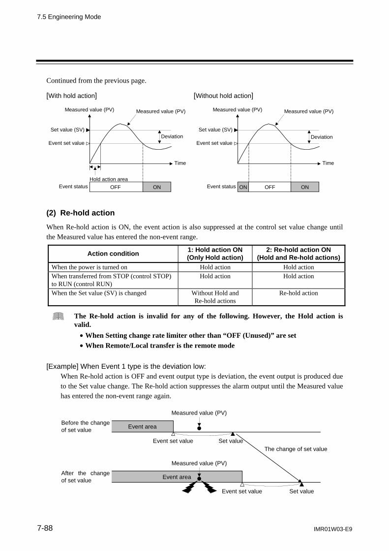
7.5 Engineering Mode
IMR01W03-E9 7-88
Continued from the previous page. [With hold action] [Without hold action]
ONON Event status
Time
Deviation
Hold action area
Measured value (PV) Measured value (PV)
Event set value
Set value (SV)
OFF
Time
Deviation
Measured value (PV)
Event set value
Set value (SV)
ON Event status OFF
Measured value (PV)
(2) Re-hold action
When Re-hold action is ON, the event action is also suppressed at the control set value change until the Measured value has entered the non-event range.
Action condition 1: Hold action ON (Only Hold action)
2: Re-hold action ON (Hold and Re-hold actions)
When the power is turned on Hold action Hold action When transferred from STOP (control STOP) to RUN (control RUN)
Hold action Hold action
When the Set value (SV) is changed Without Hold and Re-hold actions
Re-hold action
The Re-hold action is invalid for any of the following. However, the Hold action is valid. When Setting change rate limiter other than “OFF (Unused)” are set When Remote/Local transfer is the remote mode
[Example] When Event 1 type is the deviation low:
When Re-hold action is OFF and event output type is deviation, the event output is produced due to the Set value change. The Re-hold action suppresses the alarm output until the Measured value has entered the non-event range again.
Event area
Measured value (PV)
Before the change of set value
The change of set valueSet valueEvent set value
Event area After the change of set value
Measured value (PV)
Set value Event set value

7.5 Engineering Mode
IMR01W03-E9 7-89
F41.
Event 1 interlock
Use to select the Interlock function for the Event 1.
Data range Factory set value
0: Unused 1: Used
0
Related parameters Parameter setting mode: Event 1 set value (P. 7-21)
Engineering mode: Energized/De-energized (P. 7-80) Alarm (ALM) lamp lighting condition 1 (P. 7-81) Output status at STOP mode (P. 7-82) Event 1 type (P. 7-85) Event 1 hold action (P. 7-87) Event 1 differential gap (P. 7-90) Event 1 delay timer (P. 7-91) Force ON of Event 1 action (P. 7-93)
Description of function
The Event interlock function is used to hold the event state even if the Measured value (PV) is out of the event area after its entry into the area once. [Example] When the Event interlock function is used for deviation high
Event set value
Set value (SV)
Event status OFF ON
Measured value (PV)
Time
Event interlock
Deviation
Measured value (PV)
[Without Event hold action]

7.5 Engineering Mode
IMR01W03-E9 7-90
F41.
Event 1 differential gap Digital
output
OPTION
Use to set a Differential gap of the Event 1.
Data range Factory set value
When Event 1 type is deviation, input value or set value actions:
0 to Input span Varies with the setting of the Decimal point position (P. 7-71).
2 If the event type is specified by the model and suffix code when ordering, the factory set value of Event 1 differential gap differs depending on that event type.
When Event 1 type is Manipulated output value action:
0.0 to 110.0 %
Related parameters Parameter setting mode: Event 1 set value (P. 7-21)
Engineering mode: Decimal point position (P. 7-71) Energized/De-energized (P. 7-80) Alarm (ALM) lamp lighting condition 1 (P. 7-81) Output status at STOP mode (P. 7-82) Event 1 type (P. 7-85) Event 1 hold action (P. 7-87) Event 1 interlock (P. 7-89) Event 1 delay timer (P. 7-91) Force ON of Event 1 action (P. 7-93)
Description of function
It prevents chattering of event output due to the measured value fluctuation around the Event set value.
Differential gap
Measured value (PV)
Event set value
ON OFF OFF Event status
Time
Measured value (PV)
Process high
Differential gap
Measured value (PV)
Event setvalue
ON OFF OFF Event status
Time
Measured value (PV)
Process low

7.5 Engineering Mode
IMR01W03-E9 7-91
F41.
Event 1 delay timer Digital
output
OPTION
Event 1 delay timer is to set an output delay time for event outputs.
Data range Factory set value
0.0 to 600.0 seconds 0.0
Related parameters Parameter setting mode: Event 1 set value (P. 7-21)
Engineering mode: Energized/De-energized (P. 7-80) Alarm (ALM) lamp lighting condition 1 (P. 7-81) Output status at STOP mode (P. 7-82) Event 1 type (P. 7-85) Event 1 hold action (P. 7-87) Event 1 interlock (P. 7-89) Event 1 differential gap (P. 7-90) Force ON of Event 1 action (P. 7-93)
Description of function
When an event condition becomes ON status, the output is suppressed until the Delay timer set time elapses. After the time is up, if the event output is still ON status, the output will be produced.
Example: When the setting of Event 1 delay timer is 50.0 seconds
ON
Event state
Set value (SV)
Event set value
Measured value (PV)
Event 1 delay timer (50.0 seconds)
Event output ON
Event output OFF
Non-event state
Event 1 delay timer (50.0 seconds)
ALM lamp state OFF
Continued on the next page.

7.5 Engineering Mode
IMR01W03-E9 7-92
Continued from the previous page.
The Event delay timer is also activated for the following cases.
When set to the event state simultaneously with power turned on. When set to the event state simultaneously with control changed to RUN (control start)
from STOP (control stop).
In the event wait state, no event output is turned on even after the Event delay timer preset time has elapsed.
The Event delay timer is reset for the following cases. When power failure occurs while the Event delay timer is being activated. When control is changed to STOP (control stop) from RUN (control start) while the Event
delay timer is being activated.

7.5 Engineering Mode
IMR01W03-E9 7-93
F41.
Force ON of Event 1 action Digital
output
OPTION
Select the operation state that is output (force ON) as the event action.
Factory set value: 0000
Event output turned on at input error occurrence 0: Invalid 1: Valid
Event output turned on in Manual mode 0: Invalid 1: Valid
Event output turned on during the Autotuning (AT) function is being executed
0: Invalid 1: Valid Event output turned on during the Setting change rate limiter is being operated
0: Invalid 1: Valid
Related parameters Engineering mode: Input error determination point (high),
Input error determination point (low) (P. 7-74)
Continued on the next page.

7.5 Engineering Mode
IMR01W03-E9 7-94
Continued from the previous page. Description of function
Event action at input error: Example: Input range: 0 to 400 C
Input error determination point (high): 300 C Input error determination point (low): 50 C
Action area at input error Action area at input error
Differential gap (0.1 % of input span)
Input error determination point (high)
0 C 50 C 300 C 400 C
Input scale range
Forcibly turned on (1: Valid)
Normal processing (0: Invalid)
Forcibly turned on (1: Valid)
Normal processing (0: Invalid)
Select one of these
Input error determination point (low)
Select one of these
“0: Invalid”: The event output is produced depending on the selected event action status. “1: Valid”: The event output is forcibly turned on regardless of the event action status.

7.5 Engineering Mode
IMR01W03-E9 7-95
Function block 42 (F42.)
This is the first parameter symbol of Function block 42 (F42.).
F42.
Event 2 type
Use to select a action type of the Event 2.
Data range Factory set value
0: None 0
If the event type is specified by the model and suffix code when ordering, that event type becomes the factory set value.
Deviation action: 1: Deviation high 1
2: Deviation low 1
3: Deviation high/low 1
4: Band 1 Input value action: 5: Process high 1
6: Process low 1 Set value action: 7: Set value (SV) high 8: Set value (SV) low
Manipulated output value action: 10: Manipulated output value (MV1) high
[heat-side] 1, 2 11: Manipulated output value (MV1) low
[heat-side] 1, 2 12: Manipulated output value (MV2) high
[cool-side] 1 13: Manipulated output value (MV2) low
[cool-side] 1
9: Unused Do not set to “9: Unused” for Event 2.
1 Event hold action is available. 2 The Manipulated output value (MV) corresponds to the Feedback resistance
(FBR) input value when Feedback resistance (FBR) input is used.
Related parameters Parameter setting mode: Event 2 set value (P. 7-21)
Continued on the next page.
7.5 Engineering Mode
IMR01W03-E9 7-96
Continued from the previous page.
Engineering mode Output assignment (P. 7-79) Energized/De-energized (P. 7-80) Alarm (ALM) lamp lighting condition 1 (P. 7-81) Output status at STOP mode (P. 7-82) Event 2 hold action (P. 7-97) Event 2 interlock (P. 7-98) Event 2 differential gap (P. 7-99) Event 2 delay timer (P. 7-100) Force ON of Event 2 action (P. 7-101)
Description of function
For function description, refer to Event 1 type (P. 7-85).

7.5 Engineering Mode
IMR01W03-E9 7-97
F42.
Event 2 hold action
Use to set an Event hold action for the Event 2.
Data range Factory set value
0: OFF 1: Hold action ON (Only Hold action)
Validate the Hold action when the power is turned on.
Validate the Hold action when transferred from STOP (control STOP) to RUN (control RUN).
2: Re-hold action ON (Hold and Re-hold actions) Validate the Hold action when the power is
turned on. Validate the Hold action when transferred from
STOP (control STOP) to RUN (control RUN). Validate the Re-hold action when the Set value
(SV) is changed. However, if the rate of setting change limiter is set to any function other than “OFF (Unused)” or in the Remote mode, the Re-hold action becomes invalid.
0
If the event type is specified by the model and suffix code when ordering, the factory set value of Event 2 hold action differs depending on that event type.
When high alarm with Hold/Re-hold action is used for Event function, alarm does not turn on while Hold action is in operation. Use in combination with a high alarm without Hold action in order to prevent overheating which may occur by failure of control devices, such as welding of relays.
Related parameters Parameter setting mode: Event 2 set value (P. 7-21)
Engineering mode Energized/De-energized (P. 7-80) Alarm (ALM) lamp lighting condition 1 (P. 7-81) Output status at STOP mode (P. 7-82) Event 2 type (P. 7-95) Event 2 interlock (P. 7-98) Event 2 differential gap (P. 7-99) Event 2 delay timer (P. 7-100) Force ON of Event 2 action (P. 7-101)
Description of function
For function description, refer to Event 1 hold action (P. 7-87).
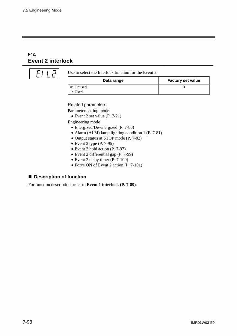
7.5 Engineering Mode
IMR01W03-E9 7-98
F42.
Event 2 interlock
Use to select the Interlock function for the Event 2.
Data range Factory set value
0: Unused 1: Used
0
Related parameters Parameter setting mode: Event 2 set value (P. 7-21)
Engineering mode Energized/De-energized (P. 7-80) Alarm (ALM) lamp lighting condition 1 (P. 7-81) Output status at STOP mode (P. 7-82) Event 2 type (P. 7-95) Event 2 hold action (P. 7-97) Event 2 differential gap (P. 7-99) Event 2 delay timer (P. 7-100) Force ON of Event 2 action (P. 7-101)
Description of function
For function description, refer to Event 1 interlock (P. 7-89).

7.5 Engineering Mode
IMR01W03-E9 7-99
F42.
Event 2 differential gap Digital
output
OPTION
Use to set a Differential gap of the Event 2.
Data range Factory set value
When Event 2 type is deviation, input value or set value actions:
0 to Input span Varies with the setting of the Decimal point position (P. 7-71).
2 If the event type is specified by the model and suffix code when ordering, the factory set value of Event 2 differential gap differs depending on that event type.
When Event 2 type is Manipulated output value action:
0.0 to 110.0 %
Related parameters Parameter setting mode: Event 2 set value (P. 7-21)
Engineering mode: Decimal point position (P. 7-71) Energized/De-energized (P. 7-80) Alarm (ALM) lamp lighting condition 1 (P. 7-81) Output status at STOP mode (P. 7-82) Event 2 type (P. 7-95) Event 2 hold action (P. 7-97) Event 2 interlock (P. 7-98) Event 2 delay timer (P. 7-100) Force ON of Event 2 action (P. 7-101)
Description of function
For function description, refer to Event 1 differential gap (P. 7-90).

7.5 Engineering Mode
IMR01W03-E9 7-100
F42.
Event 2 delay timer Digital
output
OPTION
Event 2 delay timer is to set an output delay time for event outputs.
Data range Factory set value
0.0 to 600.0 seconds 0.0
Related parameters Parameter setting mode: Event 2 set value (P. 7-21)
Engineering mode Energized/De-energized (P. 7-80) Alarm (ALM) lamp lighting condition 1 (P. 7-81) Output status at STOP mode (P. 7-82) Event 2 type (P. 7-95) Event 2 hold action (P. 7-97) Event 2 interlock (P. 7-98) Event 2 differential gap (P. 7-99) Force ON of Event 2 action (P. 7-101)
Description of function
For function description, refer to Event 1 delay timer (P. 7-91).

7.5 Engineering Mode
IMR01W03-E9 7-101
F42.
Force ON of Event 2 action Digital
output
OPTION
Select the operation state that is output (force ON) as the event action.
Factory set value: 0000
Event output turned on at input error occurrence 0: Invalid 1: Valid
Event output turned on in Manual mode 0: Invalid 1: Valid
Event output turned on during the Autotuning (AT) function is being executed
0: Invalid 1: Valid Event output turned on during the Setting change rate limiter is being operated
0: Invalid 1: Valid
Related parameters Engineering mode: Input error determination point (high),
Input error determination point (low) (P. 7-74) Description of function
For function description, refer to Force ON of Event 1 action (P. 7-93).

7.5 Engineering Mode
IMR01W03-E9 7-102
Function block 43 (F43.)
This is the first parameter symbol of Function block 43 (F43.).
F43.
Event 3 type
Use to select a action type of the Event 3.
Data range Factory set value
0: None 0
If the event type is specified by the model and suffix code when ordering, that event type becomes the factory set value.
Deviation action: 1: Deviation high 1
2: Deviation low 1
3: Deviation high/low 1
4: Band 1 Input value action: 5: Process high 1
6: Process low 1 Set value action: 7: Set value (SV) high 8: Set value (SV) low
Manipulated output value action: 10: Manipulated output value (MV1) high
[heat-side] 1, 2 11: Manipulated output value (MV1) low
[heat-side] 1, 2 12: Manipulated output value (MV2) high
[cool-side] 1 13: Manipulated output value (MV2) low
[cool-side] 1
9: Unused Do not set to “9: Unused” for Event 3.
1 Event hold action is available. 2 The Manipulated output value (MV) corresponds to the Feedback resistance (FBR)
input value when Feedback resistance (FBR) input is used.
Related parameters Parameter setting mode: Event 3 set value (P. 7-21)
Continued on the next page.

7.5 Engineering Mode
IMR01W03-E9 7-103
Continued from the previous page.
Engineering mode: Output assignment (P. 7-79) Energized/De-energized (P. 7-80) Alarm (ALM) lamp lighting condition 1 (P. 7-81) Output status at STOP mode (P. 7-82) Event 3 hold action (P. 7-104) Event 3 interlock (P. 7-105) Event 3 differential gap (P. 7-106) Event 3 delay timer (P. 7-107) Force ON of Event 3 action (P. 7-108)
Description of function
For function description, refer to Event 1 type (P. 7-85).

7.5 Engineering Mode
IMR01W03-E9 7-104
F43.
Event 3 hold action
Use to set an Event hold action for the Event 3.
Data range Factory set value
0: OFF 1: Hold action ON (Only Hold action)
Validate the Hold action when the power is turned on.
Validate the Hold action when transferred from STOP (control STOP) to RUN (control RUN).
2: Re-hold action ON (Hold and Re-hold actions) Validate the Hold action when the power is
turned on. Validate the Hold action when transferred from
STOP (control STOP) to RUN (control RUN). Validate the Re-hold action when the Set value
(SV) is changed. However, if the rate of setting change limiter is set to any function other than “OFF (Unused)” or in the Remote mode, the Re-hold action becomes invalid.
0
If the event type is specified by the model and suffix code when ordering, the factory set value of Event 3 hold action differs depending on that event type.
When high alarm with Hold/Re-hold action is used for Event function, alarm does not turn on while Hold action is in operation. Use in combination with a high alarm without Hold action in order to prevent overheating which may occur by failure of control devices, such as welding of relays.
Related parameters Parameter setting mode: Event 3 set value (P. 7-21)
Engineering mode: Energized/De-energized (P. 7-80) Alarm (ALM) lamp lighting condition 1 (P. 7-81) Output status at STOP mode (P. 7-82) Event 3 type (P. 7-102) Event 3 interlock (P. 7-105) Event 3 differential gap (P. 7-106) Event 3 delay timer (P. 7-107) Force ON of Event 3 action (P. 7-108)
Description of function
For function description, refer to Event 1 hold action (P. 7-87).

7.5 Engineering Mode
IMR01W03-E9 7-105
F43.
Event 3 interlock
Use to select the Interlock function for the Event 3.
Data range Factory set value
0: Unused 1: Used
0
Related parameters Parameter setting mode: Event 3 set value (P. 7-21)
Engineering mode: Energized/De-energized (P. 7-80) Alarm (ALM) lamp lighting condition 1 (P. 7-81) Output status at STOP mode (P. 7-82) Event 3 type (P. 7-102) Event 3 hold action (P. 7-104) Event 3 differential gap (P. 7-106) Event 3 delay timer (P. 7-107) Force ON of Event 3 action (P. 7-108)
Description of function
For function description, refer to Event 1 interlock (P. 7-89).

7.5 Engineering Mode
IMR01W03-E9 7-106
F43.
Event 3 differential gap Digital
output
OPTION
Use to set a Differential gap of the Event 3.
Data range Factory set value
When Event 3 type is deviation, input value or set value actions:
0 to Input span Varies with the setting of the Decimal point position (P. 7-71).
2 If the event type is specified by the model and suffix code when ordering, the factory set value of Event 3 differential gap differs depending on that event type.
When Event 3 type is Manipulated output value action:
0.0 to 110.0 %
Related parameters Parameter setting mode: Event 3 set value (P. 7-21)
Engineering mode: Decimal point position (P. 7-71) Energized/De-energized (P. 7-80) Alarm (ALM) lamp lighting condition 1 (P. 7-81) Output status at STOP mode (P. 7-82) Event 3 type (P. 7-102) Event 3 hold action (P. 7-104) Event 3 interlock (P. 7-105) Event 3 delay timer (P. 7-107) Force ON of Event 3 action (P. 7-108)
Description of function
For function description, refer to Event 1 differential gap (P. 7-90).

7.5 Engineering Mode
IMR01W03-E9 7-107
F43.
Event 3 delay timer Digital
output
OPTION
Event 3 delay timer is to set an output delay time for event outputs.
Data range Factory set value
0.0 to 600.0 seconds 0.0
Related parameters Parameter setting mode: Event 3 set value (P. 7-21)
Engineering mode: Energized/De-energized (P. 7-80) Alarm (ALM) lamp lighting condition 1 (P. 7-81) Output status at STOP mode (P. 7-82) Event 3 type (P. 7-102) Event 3 hold action (P. 7-104) Event 3 interlock (P. 7-105) Event 3 differential gap (P. 7-106) Force ON of Event 3 action (P. 7-108)
Description of function
For function description, refer to Event 1 delay timer (P. 7-91).

7.5 Engineering Mode
IMR01W03-E9 7-108
F43.
Force ON of Event 3 action Digital
output
OPTION
Select the operation state that is output (force ON) as the event action.
Factory set value: 0000
Event output turned on at input error occurrence 0: Invalid 1: Valid
Event output turned on in Manual mode 0: Invalid 1: Valid
Event output turned on during the Autotuning (AT) function is being execute
0: Invalid 1: Valid Event output turned on during the Setting change rate limiter is being operated
0: Invalid 1: Valid
Related parameters Engineering mode Input error determination point (high),
Input error determination point (low) (P. 7-74) Description of function
For function description, refer to Force ON of Event 1 action (P. 7-93).

7.5 Engineering Mode
IMR01W03-E9 7-109
Function block 44 (F44.)
This is the first parameter symbol of Function block 44 (F44.).
F44.
Event 4 type
Use to select a action type of the Event 4.
Data range Factory set value
0: None 0
If the event type is specified by the model and suffix code when ordering, that event type becomes the factory set value.
Deviation action: 1: Deviation high 1
2: Deviation low 1
3: Deviation high/low 1
4: Band 1 Input value action: 5: Process high 1
6: Process low 1 Set value action: 7: Set value (SV) high 8: Set value (SV) low
Alarm action: 9: Control loop break alarm (LBA)
Manipulated output value action: 10: Manipulated output value (MV1) high
[heat-side] 1, 2 11: Manipulated output value (MV1) low
[heat-side] 1, 2 12: Manipulated output value (MV2) high
[cool-side] 1 13: Manipulated output value (MV2) low
[cool-side] 1
1 Event hold action is available. 2 The Manipulated output value (MV) corresponds to the Feedback resistance (FBR)
input value when Feedback resistance (FBR) input is used.
Related parameters Parameter setting mode: Event 4 set value (P. 7-21) Control loop break alarm (LBA) time (P. 7-22) LBA deadband (P. 7-23)
Continued on the next page.

7.5 Engineering Mode
IMR01W03-E9 7-110
Continued from the previous page.
Engineering mode: Output assignment (P. 7-79) Event 4 hold action (P. 7-111) Energized/De-energized (P. 7-80) Event 4 interlock (P. 7-112) Alarm (ALM) lamp lighting Event 4 differential gap (P. 7-113) condition 1 (P. 7-81) Event 4 delay timer (P. 7-114) Output status at STOP mode Force ON of Event 4 action (P. 7-82) (P. 7-115)
Description of function For a description of functions other than the Control loop break alarm (LBA) function, to Event 1 type (P. 7-85). Control loop break alarm (LBA) The Control loop break alarm (LBA) function is used to detect a load (heater) break or a failure in the external actuator (magnet relay, etc.), or a failure in the control loop caused by an input (sensor) break. The LBA function is activated when control output reaches 0 % (low limit with output limit function) or 100 % (high limit with output limit function). LBA monitors variation of the Measured value (PV) for the length of LBA time. When the LBA time has elapsed and the PV is still within the alarm determination range, the LBA will be ON.
The LBA function produces the alarm when any of the following conditions occurs. LBA determination range: TC/RTD inputs: 2 C [F] (fixed) Voltage/Current inputs: 0.2 % of input span (fixed)
When the control output reaches 0 % (low limit with output limit function) For direct action: When the LBA time has passed and the PV has not risen beyond the alarm
determination range, the alarm will be turned on. For reverse action: When the LBA time has passed and the PV has not fallen below the alarm
determination range, the alarm will be turned on. When the output exceeds 100 % (low limit with output high function)
For direct action: When the LBA time has passed and the PV has not fallen below the alarm determination range, the alarm will be turned on.
For reverse action: When the LBA time has passed and the PV has not risen beyond the alarm determination range, the alarm will be turned on.
If the Autotuning function is used, the LBA time is automatically set twice as large as the Integral time. The LBA setting time will not be changed even if the Integral time is changed. LBA function is not operative when: AT function is activated The controller is in STOP mode The control type is Heat/Cool PID control LBA function is set to “0.” LBA function is not assigned to Event 4 (ES4). The LBA function does not detect a location which causes alarm status. If LBA alarm is ON, check each device or wiring of the control loop. While the LBA is ON (under alarm status), the following conditions cancel the alarm status and LBA will be OFF: The Measured value (PV) rises beyond (or falls below) the LBA determination range within
the LBA setting time. The Measured value (PV) enters within the LBA deadband.

7.5 Engineering Mode
IMR01W03-E9 7-111
F44.
Event 4 hold action
Use to set an Event hold action for the Event 4.
Data range Factory set value
0: OFF 1: Hold action ON (Only Hold action)
Validate the Hold action when the power is turned on.
Validate the Hold action when transferred from STOP (control STOP) to RUN (control RUN).
2: Re-hold action ON (Hold and Re-hold actions) Validate the Hold action when the power is
turned on. Validate the Hold action when transferred from
STOP (control STOP) to RUN (control RUN). Validate the Re-hold action when the Set value
(SV) is changed. However, if the rate of setting change limiter is set to any function other than “OFF (Unused)” or in the Remote mode, the Re-hold action becomes invalid.
0
If the event type is specified by the model and suffix code when ordering, the factory set value of Event 4 hold action differs depending on that event type.
When high alarm with Hold/Re-hold action is used for Event function, alarm does not turn on while Hold action is in operation. Use in combination with a high alarm without Hold action in order to prevent overheating which may occur by failure of control devices, such as welding of relays.
Related parameters Parameter setting mode: Event 4 set value (P. 7-21)
Engineering mode: Energized/De-energized (P. 7-80) Alarm (ALM) lamp lighting condition 1 (P. 7-81) Output status at STOP mode (P. 7-82) Event 4 type (P. 7-109) Event 4 interlock (P. 7-112) Event 4 differential gap (P. 7-113) Event 4 delay timer (P. 7-114) Force ON of Event 4 action (P. 7-115)
Description of function
For function description, refer to Event 1 hold action (P. 7-87).

7.5 Engineering Mode
IMR01W03-E9 7-112
F44.
Event 4 interlock
Use to select the Interlock function for the Event 4.
Data range Factory set value
0: Unused 1: Used
0
Related parameters Parameter setting mode: Event 4 set value (P. 7-21) Control loop break alarm (LBA) time (P. 7-22) LBA deadband (P. 7-23)
Engineering mode: Energized/De-energized (P. 7-80) Alarm (ALM) lamp lighting condition 1 (P. 7-81) Output status at STOP mode (P. 7-82) Event 4 type (P. 7-109) Event 4 hold action (P. 7-111) Event 4 differential gap (P. 7-113) Event 4 delay timer (P. 7-114) Force ON of Event 4 action (P. 7-115)
Description of function
For function description, refer to Event 1 interlock (P. 7-89).

7.5 Engineering Mode
IMR01W03-E9 7-113
F44.
Event 4 differential gap Digital
output
OPTION
Use to set a Differential gap of the Event 4.
Data range Factory set value
When Event 4 type is deviation, input value or set value actions:
0 to Input span Varies with the setting of the Decimal point position (P. 7-71).
2 If the event type is specified by the model and suffix code when ordering, the factory set value of Event 4 differential gap differs depending on that event type.
When Event 4 type is Manipulated output value action:
0.0 to 110.0 %
For the Control loop break alarm (LBA), invalidated even if a differential gap is set.
Related parameters Parameter setting mode Event 4 set value (P. 7-21)
Engineering mode: Decimal point position (P. 7-71) Energized/De-energized (P. 7-80) Alarm (ALM) lamp lighting condition 1 (P. 7-81) Output status at STOP mode (P. 7-82) Event 4 type (P. 7-109) Event 4 hold action (P. 7-111) Event 4 interlock (P. 7-112) Event 4 delay timer (P. 7-114) Force ON of Event 4 action (P. 7-115)
Description of function
For function description, refer to Event 1 differential gap (P. 7-90).

7.5 Engineering Mode
IMR01W03-E9 7-114
F44.
Event 4 delay timer Digital
output
OPTION
Event 4 delay timer is to set an output delay time for event outputs.
Data range Factory set value
0.0 to 600.0 seconds 0.0
Related parameters Parameter setting mode: Event 4 set value (P. 7-21) Control loop break alarm (LBA) time (P. 7-22) LBA deadband (P. 7-23)
Engineering mode: Energized/De-energized (P. 7-80) Alarm (ALM) lamp lighting condition 1 (P. 7-81) Output status at STOP mode (P. 7-82) Event 4 type (P. 7-109) Event 4 hold action (P. 7-111) Event 4 interlock (P. 7-112) Event 4 differential gap (P. 7-113) Force ON of Event 4 action (P. 7-115)
Description of function
For function description, refer to Event 1 delay timer (P. 7-91).

7.5 Engineering Mode
IMR01W03-E9 7-115
F44.
Force ON of Event 4 action Digital
output
OPTION
Select the operation state that is output (force ON) as the event action.
Factory set value: 0000
Event output turned on at input error occurrence 0: Invalid 1: Valid
Event output turned on in Manual mode 0: Invalid 1: Valid
Event output turned on during the Autotuning (AT) function is being executed
0: Invalid 1: Valid Event output turned on during the Setting change rate limiter is being operated
0: Invalid 1: Valid
For the Control loop break alarm (LBA), invalidated even if the Force ON of Event 4 action is set.
Related parameters Engineering mode: Input error determination point (high),
Input error determination point (low) (P. 7-74) Description of function
For function description, refer to Force ON of Event 1 action (P. 7-93).

7.5 Engineering Mode
IMR01W03-E9 7-116
Function block 45 (F45.)
This is the first parameter symbol of Function block 45 (F45.). The settings of parameters in this group become valid on the controller with the CT input (optional) function. In addition, in order to output the Heater break alarm it is necessary to specify Output 2 (OUT2) or Digital output (optional).
F45.
CT1 ratio CT
input
OPTION
Digitaloutput
OPTION
Use to set the number of turns in the Current transformer which is used to monitor the current flowing through the load. There are two types of dedicated Current transformers. The set value differs depending on the Current transformer (CT) type.
Data range Factory set value
0 to 9999 Set the appropriate values below for each Current transformer type. CTL-6-P-N: 800 CTL-12-S56-10L-N: 1000
If the Current transformer (CT) type is not specified when the order is placed: 800 If CTL-6-P-N is specified for the Current transformer (CT) type: 800
If CTL-12-S56-10L-N is specified for the Current transformer (CT) type: 1000
Related parameters Setup setting mode: Heater break alarm 1 (HBA1) set value (P. 7-35) Heater break determination point 1 (P. 7-38) Heater melting determination point 1 (P. 7-39)
Engineering mode: CT1 assignment (P. 7-117) Heater break alarm 1 (HBA1) type (P. 7-118)

7.5 Engineering Mode
IMR01W03-E9 7-117
F45.
CT1 assignment CT
input
OPTION
Digitaloutput
OPTION
Use to assign the Current transformer (CT) input to an output from OUT1 or OUT2. The CT input 1 is tied to HBA1, and the CT input 2 tied to HBA2, so when CT1 is assigned to OUT1, HBA1 is also automatically assigned to OUT1.
Data range Factory set value
0: None (Heater break alarm function OFF) 1: OUT1 2: OUT2 3 to 6: Do not set this one
1
To use HBA for a three-phase load, both CT inputs can be assigned to the same output.
Related parameters Setup setting mode: Engineering mode: Heater break alarm 1 (HBA1) Output assignment (P. 7-79) set value (P. 7-35) CT1 ratio (P. 7-116) Heater break determination Heater break alarm 1 (HBA1) point 1 (P. 7-38) type (P. 7-117) Heater melting determination point 1 (P. 7-39)
F45.
Heater break alarm 1 (HBA1) type CT
input
OPTION
Digitaloutput
OPTION
Use to select the Heater break alarm 1 (HBA1) type.
Data range Factory set value
0: Heater break alarm 1 (HBA1) type A The type A corresponds to the time-proportional control output.
1: Heater break alarm 1 (HBA1) type B The type B corresponds to the continuous control output.
Varies with the type of control output (OUT1) being specified at ordering. Relay, Voltage pulse, Triac, or Open-collector output: 0 Voltage/Current continuous output: 1
Related parameters Setup setting mode: Heater break alarm 1 (HBA1) set value (P. 7-35) Heater break determination point 1 (P. 7-38) Heater melting determination point 1 (P. 7-39)

7.5 Engineering Mode
IMR01W03-E9 7-118
Engineering mode: Output assignment (P. 7-79) CT1 ratio (P. 7-116) CT1 assignment (P. 7-117) Number of heater break alarm 1 (HBA1) delay times (P. 7-119)
Description of function
Heater break alarm (HBA) type A: Heater break alarm (HBA) type A can be used with time-proportional control output (Relay, Voltage pulse, Triac or Open-collector output). The HBA function monitors the current flowing through the load by a dedicated Current transformer (CT), compares the measured value with the HBA set values, and detects a fault in the heating circuit.
Heater break alarm (HBA) type B:
Heater break alarm (HBA) type B can be used with continuous control output (Voltage/Current continuous output). The HBA function assumes that the heater current value is proportional * to the control output value of the controller, otherwise viewed as the Manipulated variable (MV), and compare it with the CT input value to detect a fault in the heating or cooling circuit. However, in the case of time-proportional control output, an alarm status is only detected when the output device is melting.
* It is assumed that the current value flowing through the load is at maximum when the control output from the controller is 100 %, and the minimum current value flowing through the load is zero (0) when the control output from the controller is 0 %.
When changing the value of CT assignment, the type of Heater break alarm (HBA) automatically changes.
CT assignment HBA Type
1: OUT1 Type A (for time-proportional control output) or Type B (for continuous control output) 2: OUT2
0: None Type A
Example: OUT1: Relay contact output, OUT2: Voltage/Current continuous output
When changing the value of CT assignment from OUT1 to OUT2, the type of Heater break alarm (HBA) automatically changes from Type A to B.

7.5 Engineering Mode
IMR01W03-E9 7-119
F45.
Number of heater break alarm 1 (HBA1) delay times
CT input
OPTION
Digitaloutput
OPTION
To prevent producing a false alarm, the alarm function waits to produce an alarm status until the measured CT input value is in an alarm range for the preset number of consecutive sampling cycles (Sampling cycle of CT input 5).
Data range Factory set value
0 to 255 5
Related parameters Setup setting mode: Heater break alarm 1 (HBA1) set value (P. 7-35) Heater break determination point 1 (P. 7-38) Heater melting determination point 1 (P. 7-39)
Engineering mode: Output assignment (P. 7-79) CT1 ratio (P. 7-116) CT1 assignment (P. 7-117) Heater break alarm 1 (HBA1) type (P. 7-117)
Description of function
Heater break alarm (HBA) delay time Number of delay times Sampling time * * Twice of the measured input sampling cycle
Example: Sampling time: 200 ms (Twice of the measured input sampling cycle [100ms]) Number of delay times: 5 times (factory set value)
HBA delay time 5 times 200 ms 1000 ms 1.0 seconds
HBA state
ON
OFF
HBA ON state
HBA ON
HBA delay time

7.5 Engineering Mode
IMR01W03-E9 7-120
Function block 46 (F46.)
This is the first parameter symbol of Function block 46 (F46.). The settings of parameters in this group become valid on the controller with the CT input (optional) function. In addition, in order to output the Heater break alarm it is necessary to specify Output 2 (OUT2) or Digital output (optional).
F46.
CT2 ratio CT
input
OPTION
Digitaloutput
OPTION
Use to set the number of turns in the Current transformer which is used to monitor the current flowing through the load. There are two types of dedicated Current transformers.
Data range Factory set value
0 to 9999 Set the appropriate values below for each Current transformer type. CTL-6-P-N: 800 CTL-12-S56-10L-N: 1000
If the Current transformer (CT) type is not specified when the order is placed: 800 If CTL-6-P-N is specified for the Current transformer (CT) type: 800
If CTL-12-S56-10L-N is specified for the Current transformer (CT) type: 1000
Related parameters Setup setting mode: Heater break alarm 2 (HBA2) set value (P. 7-35) Heater break determination point 2 (P. 7-38) Heater melting determination point 2 (P. 7-39)
Engineering mode: CT2 assignment (P. 7-121) Heater break alarm 2 (HBA2) type (P. 7-122)
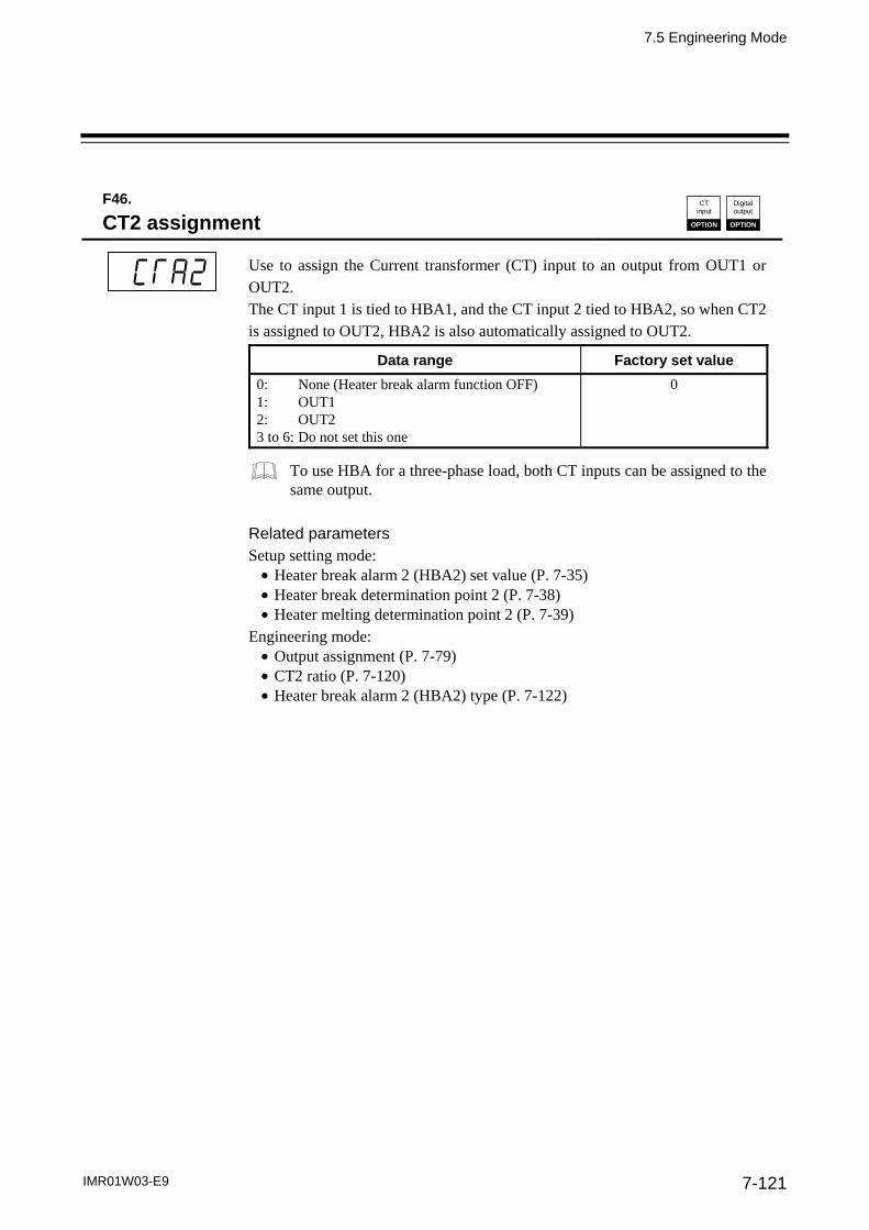
7.5 Engineering Mode
IMR01W03-E9 7-121
F46.
CT2 assignment CT
input
OPTION
Digitaloutput
OPTION
Use to assign the Current transformer (CT) input to an output from OUT1 or OUT2. The CT input 1 is tied to HBA1, and the CT input 2 tied to HBA2, so when CT2 is assigned to OUT2, HBA2 is also automatically assigned to OUT2.
Data range Factory set value
0: None (Heater break alarm function OFF) 1: OUT1 2: OUT2 3 to 6: Do not set this one
0
To use HBA for a three-phase load, both CT inputs can be assigned to the same output.
Related parameters Setup setting mode: Heater break alarm 2 (HBA2) set value (P. 7-35) Heater break determination point 2 (P. 7-38) Heater melting determination point 2 (P. 7-39)
Engineering mode: Output assignment (P. 7-79) CT2 ratio (P. 7-120) Heater break alarm 2 (HBA2) type (P. 7-122)

7.5 Engineering Mode
IMR01W03-E9 7-122
F46.
Heater break alarm 2 (HBA2) type CT
input
OPTION
Digitaloutput
OPTION
Use to select the Heater break alarm 2 (HBA2) type.
Data range Factory set value
0: Heater break alarm 2 (HBA2) type A The type A corresponds to the time- proportional control output.
1: Heater break alarm 2 (HBA2) type B The type B corresponds to the continuous control output.
0
Related parameters Setup setting mode: Heater break alarm 2 (HBA2) set value (P. 7-35) Heater break determination point 2 (P. 7-38) Heater melting determination point 2 (P. 7-39)
Engineering mode: Output assignment (P. 7-79) CT2 ratio (P. 7-120) CT2 assignment (P. 7-121) Number of heater break alarm 2 (HBA2) delay times (P. 7-122)
Description of function For function description, refer to Heater break alarm 1 (HBA1) type (P. 7-118). F46.
Number of heater break alarm 2 (HBA2) delay times
CT input
OPTION
Digitaloutput
OPTION
To prevent producing a false alarm, the alarm function waits to produce an alarm status until the measured CT input value is in an alarm range for the preset number of consecutive sampling cycles (Sampling cycle of CT input 5).
Data range Factory set value
0 to 255 5
Related parameters Setup setting mode: Heater break alarm 2 (HBA2) set value (P. 7-35) Heater break determination point 2 (P. 7-38) Heater melting determination point 2 (P. 7-39)
Engineering mode: Output assignment (P. 7-79) CT2 assignment (P. 7-121) CT2 ratio (P. 7-120) Heater break alarm 2 (HBA2) type (P. 7-122)
Description of function For function description, refer to Number of heater break alarm 1 (HBA1) delay times (P. 7-119).

7.5 Engineering Mode
IMR01W03-E9 7-123
Function block 50 (F50.)
This is the first parameter symbol of Function block 50 (F50.).
F50.
Hot/Cold start
Use to select the start mode at power recovery.
Data range Factory set value
0: Hot start 1 2: Cold start 1: Hot start 2 3: STOP start
0
Related parameters Operation mode: Auto/Manual transfer (P. 7-17)
Engineering mode: Start determination point (P. 7-124) Manipulated output value (MV1) at STOP mode, Manipulated output value (MV2) at STOP mode (P. 7-136) Output limiter low (MV1), Output limiter low (MV2) (P. 7-138) Valve action at STOP (P. 7-160)
Description of function The operation of this instrument is not affected by a power failure of 20 ms or less. The control start mode at power recovery after more than 20 ms power failure can be selected as follows.
Action when power failure
recovers
Operation mode when powerfailure recovers
Output value when power failure recovers
Hot start 1 Same as that before power failure Near the output value before power failure occurs.
Hot start 2 Same as that before power failureAuto mode Value as a result of control
computation 2 Manual mode Output limiter low 3
Cold start Manual Output limiter low 3
STOP start Started in the control stop (STOP) state regardless of the RUN mode before power failure. 1
Manipulated output value at STOP mode 3
Factory set value: Hot start 1 1 If changed to RUN from STOP by RUN/STOP transfer after start, set to the operation mode before power
failure occurs. 2 The result of control computation varies with the control response parameter. 3 If there is no Feedback resistance (FBR) input in Position proportioning PID control, the following results.
Hot start 2 (Manual mode): No output (no control motor is driven) Cold start: No output (no control motor is driven) STOP start: In accordance with the setting of valve action at STOP
Continued on the next page.

7.5 Engineering Mode
IMR01W03-E9 7-124
Continued from the previous page.
If the Startup tuning (ST) function is executed or an automatic temperature rise is made just when the power is turned on or selection is made from STOP to RUN as one of the startup conditions, control starts at Hot start 2 even if set to Hot start 1 (factory set value).
F50.
Start determination point
Determination point always set to Hot start 1 when recovered from power failure.
Data range Factory set value
0 to Input span (The unit is the same as input value.) (0: Operation starts from any start state selected by
Hot/Cold start.)
Varies with the setting of the Decimal point position (P. 7-71).
3 % of input span
Related parameter Engineering mode: Decimal point position (P. 7-71) Hot/Cold start (P. 7-123)
Description of function
The start state is determined according to the Measured value (PV) level [deviation from set value] at power recovery.
When a Measured value (PV) is between the determination points on the (plus) and (minus) sides, always started from Hot start 1 when recovered.
When a Measured value (PV) is out of the determination points or the Start determination point is set at “0,” operation starts from any start state selected by Hot/Cold start.
Start determination point
(minus side) Start determination point
(plus side)
Start determination point setting Set value (SV)
Hot start 1 Hot start 1, Hot start 2, Cold start or STOP start
Low High
Hot start 1, Hot start 2, Cold start or STOP start

7.5 Engineering Mode
IMR01W03-E9 7-125
F50.
External input type Commu-
nication
OPTION
Use to select the type of external input.
Data range Factory set value
0: Remote setting (RS) input 1: Intercontroller communication cascade control 2: Intercontroller communication ratio setting
0
Intercontroller communication cascade control or Intercontroller communication ratio setting can be performed when the port of Communication 2 is ready to be used and also the Communication 2 protocol (CMP2) is set to “2: Intercontroller communication.”
When cascade control or ratio setting is performed, the master controller is set to “0: Remote setting (RS) input.” Set each slave controller to “1: Intercontroller communication cascade control” or “2: Intercontroller communication ratio setting.”
For the Remote setting (RS) input, refer to 6.8 Remote/Local Transfer (P. 6-28). For the cascade control, refer to 6.14.5 Cascade control function (P. 6-82). For the ratio setting, refer to 6.14.6 Ratio setting function (P. 6-91).
Related parameters Operation mode: Remote/Local transfer (P. 7-18)
Engineering mode: Master channel selection (P. 7-126) Communication 2 protocol (P. 7-166)

7.5 Engineering Mode
IMR01W03-E9 7-126
F50.
Master channel selection Commu-
nication
OPTION
Set the master controller address set by Device address2 (Add2) to Master channel selection (MCH) of each slave controller. This setting is necessary for the slave controller to identify the master controller when Intercontroller cascade control or Intercontroller ratio setting is performed.
Data range Factory set value
0 to 31 0
This setting is valid when the Master channel selection is set to “1: Intercontroller communication cascade control” or “2: Intercontroller communication ratio setting.”
Related parameters Setup setting mode: Device address 2 (P. 7-44)
Engineering mode: External input type (P. 7-125)
Application: When used in the following condition
Intercontroller communication: Cascade control or ratio setting Address 0: Master controller Address 1 and Address 2: Slave controllers
Address 2
Set the address by Device address 2 (Add2) screen.
Master controller
Address 0
Set the address by Device address 2 (Add2) screen.
Cascade control or Ratio setting via Intercontroller communication
External input type (CAM): Set to 0 (Remote setting input).
Master channel selection (MCH): The Master channel selection is invalid.
Slave controller
Address 1
Set the address by Device address 2 (Add2) screen.
External input type (CAM):
Set to 1 (Intercontroller communication cascade control) or 2 (Intercontroller communication ratio setting).
Master channel selection (MCH):
Set the address “0” of master controller.
Set the address of master controller set by Device address 2 (Add2) screen to the master channel selection.
Slave controller
External input type (CAM):
Set to 1 (Intercontroller communication cascade control) or 2 (Intercontroller communication ratio setting).
Master channel selection (MCH):
Set the address “0” of master contro ller.
Set the address of master controller set by Device address 2 (Add2) screen to the master channel selection.

7.5 Engineering Mode
IMR01W03-E9 7-127
F50.
SV tracking
To select Use/Unuse of SV tracking.
Data range Factory set value
0: Unused 1: Used
1
Related parameter Operation mode: Remote/Local transfer (P. 7-18)
Description of function
With SV tracking function, when Remote/Local mode is transferred from Remote to Local, the set value used in Remote mode before the mode transfer will be kept using in Local mode to prevent rapid set value change.
Operation mode: Local Remote Local
Set value used Local set value Remote set value Local set value
SV tracking used Local set value Remote set value Local set value Remote set value Local set value Remote set value
SV tracking unused Local set value Remote set value Local set value Remote set value Local set value Remote set value
Time (t)
Set value (SV)
Remote set value
Remote/Local transferred point
(SV tracking used)
Local set value
Time (t)
Set value (SV)
Remote/Local transferred point
(SV tracking unused)
Remote set value
Local set value

7.5 Engineering Mode
IMR01W03-E9 7-128
F50.
MV transfer function
The Manipulated output value used for manual control is selected when the Operation mode in changed to the Manual mode from the Auto mode.
Data range Factory set value
0: Manipulated output value (MV1 or MV2) in Auto mode is used. [Balanceless/Bumpless function]
1: When selected by Digital input (DI): Manipulated output value (MV1 or MV2) in previous Manual mode is used. [MV transfer function]
When selected by front key: Manipulated output value (MV1 or MV2) in Auto mode is used. [Balanceless/Bumpless function]
2: Manipulated output value (MV1 or MV2) in previous Manual mode is used. [MV transfer function]
0 (Balanceless/Bumpless function)
Related parameters SV setting & monitor mode: Manipulated output value at MV transfer (P. 7-11)
Operation mode: Auto/Manual transfer (P. 7-17)
For the Balanceless/bumpless function, refer to 6.7 Auto/Manual Transfer (P. 6-23).
F50.
PV transfer function
It is selected whether or not Measured value (PV) with the operation mode transferred to Auto mode from Manual mode is used as Set value (SV). It is possible to prevent a Manipulated output value (MV) from its sudden change by substituting Measured value (PV) for Set value (SV).
Data range Factory set value
0: Unused 1: Used
0
Related parameter Operation mode: Auto/Manual transfer (P. 7-17)

7.5 Engineering Mode
IMR01W03-E9 7-129
Function block 51 (F51.)
This is the first parameter symbol of Function block 51 (F51.).
F51.
Control action
Use to select the action type of control.
Data range Factory set value
0: Brilliant II PID control (direct action) 1: Brilliant II PID control (reverse action) 2: Brilliant II Heat/Cool PID control [water cooling] 3: Brilliant II Heat/Cool PID control [air cooling] 4: Brilliant II Heat/Cool PID control [Cooling gain linear type] 5: Brilliant II Position proportioning PID control (reverse action) 6: Brilliant II Position proportioning PID control (direct action)
1
If the control action is specified by the model and suffix code when ordering, that control action becomes the factory set value.
With Output 2 (OUT2) optional, Heat/Cool PID control and Position proportioning PID control can be set.
Description of function
PID control (direct action) The Manipulated output value (MV) increases as the Measured value (PV) increases. This action is used generally for cool control.
PID control (reverse action)
The Manipulated output value (MV) decreases as the Measured value (PV) increases. This action is used generally for heat control.
MV MV
Direct action PV PV
Reverse action

7.5 Engineering Mode
IMR01W03-E9 7-130
Heat/Cool PID control In Heat/Cool control, only one controller enables heat and cool control. For example, this is effective when cool control is required in extruder cylinder temperature control.
Water cooling/Air cooling: The algorithm assuming plastic molding machine Heat/Cool control is employed. Even in equipment provided with a cooling mechanism having nonlinear characteristics, it responds quickly to attain the characteristic responding to the set value with small overshooting.
Cooling gain linear type: The algorithm assuming applications without nonlinear cooling capability is employed.
Manipulated output
value (MV)
100 %
0 %
Manipulated output value (MV1) [heat-side]
Proportional band[heat-side]
Set value (SV)
OL DB DB: Deadband
Temperature
Proportional band[cool-side]
OL: Overlap
Manipulated output value (MV2) [cool-side]
Position proportioning PID control
Position proportioning PID control converts the control output value of the controller into the corresponding signal to control a motor driven valve (control motor) and then performs temperature control of a controlled object by regulating fluid flow. In Position proportioning PID control of this controller, it is possible to select the presence or absence of Feedback resistance (FBR) input which monitors the degree of valve opening (necessary to be selected when ordering). In addition, the direct action or reverse action can be selected.
Power supply to control motor
FB400/900
TC
Controlled object
Control motor
WIPER
CLOSE
OPEN M
Liquids
11
12
9
10
17
18
19
23
24
[Connection example]
When the Feedback resistance (FBR) is provided, terminal numbers from 17 to 19 can be availed.
OUT1 (open-side)
OUT2 (close-side)

7.5 Engineering Mode
IMR01W03-E9 7-131
The details of setting differ depending on the presence or absence of Feedback resistance (FBR) input.
When the Feedback resistance (FBR) is provided: High/Low limit of valve position (limit value of FBR input) can be set.
[Output limiter high, Output limiter low] The valve position can be manually changed. [Manipulated output value (MV) setting in Manual mode] The feedback adjustment is necessary. [Feedback adjustment preparation] Action taken when Feedback resistance (FBR) input breaks can be selected.
[Action at Feedback resistance (FBR) input error] Output value (FBR input) with the output turned on or off when the Autotuning (AT) function is
executed can be restricted. [Output value with AT turned on, Output value with AT turned off] The close-side (or open-side) output remains ON when the valve position is fully closed (or opened).
[Action at saturated output]
When the Feedback resistance (FBR) is not provided: Control motor operation can be restricted by the Integrated output limiter. [Integrated output limiter] The UP/DOWN key is used to output opening or closing signal in Manual mode.
UP key (open-side): While the UP key is being pressed, open-side output (OUT1) is output continuously. Releasing the UP key turns off the output on the open-side to hold the opened state at that time.
DOWN key (close-side): While the DOWN key is being pressed, close-side output (OUT2) is output continuously. Releasing the DOWN key turns off the output on the closed-side to hold the opened state at that time.
Parameter Valid/Invalid depending on the presence or absence of FBR input (×: Valid, : Invalid)
Parameter (Engineering mode)
When the Feedback resistance(FBR) input is provided
When the Feedback resistance(FBR) input is not provided
Manipulated output value (MV1) at STOP mode ×
Output limiter high [MV1] Output limiter low [MV1]
×
Output value with AT turned on Output value with AT turned on
×
Open/Close output neutral zone * × ×
Open/Close output differential gap * × ×
Action at Feedback resistance (FBR) input error ×
Feedback adjustment ×
Control motor time * × ×
Integrated output limiter ×
Valve action at STOP * × ×
Action at saturated output ×
* Always set this item regardless of the presence or absence of opening Feedback resistance (FBR) input.
Position proportioning PID control can be performed if two output points are selected when ordering. When the control action is the Position proportioning PID control, the Startup tuning (ST) is not availed. In addition, the Output change rate limiter is invalid. For the setting method of Position proportioning PID control, refer to 6.12 Position Proportioning PID Control (P. 6-40).

7.5 Engineering Mode
IMR01W03-E9 7-132
Brilliant II PID control PID control is a control method of achieving stabilized control result by setting P (Proportional band), I (Integral time) and D (Derivative time) constants, and is widely used. However with this PID control if P, I and D values are set to focus on “better response to control set value change,” “response to external disturbance” deteriorates. In contrast, if PID values are set to focus on “better response to external disturbance,” “response to control set value change” deteriorates. In brilliant II PID control a form of “response to control set value change” can be selected from among Fast, Medium and Slow with PID constants remaining unchanged so as to be in good “response to external disturbance.” In addition, the controller is provided with the function which restricts the amount of undershooting caused by the cooling nonlinear characteristic possessed by plastic molding machines when the Set value (SV) is lowered in Heat/Cool PID control.
Ordinary PID
P, I and D constants set so as to be in good response to set value change
Response to set value change Response to disturbance change
Set value Set value
Set value Set value
Response to set value change Response to disturbance change
P, I and D constants set so as to be in good response to disturbance
Response to set value change Response to disturbance change
Brilliant II PID control
Set value Set value
Fast
Medium
Slow
Restriction of undershooting when the set value (SV) is lowered
Set value
The undershoot factor is small.
The undershoot factor is large.

7.5 Engineering Mode
IMR01W03-E9 7-133
F51.
Integral/Derivative time decimal point position
Use to select a Decimal point position of Integral time and Derivative time.
Data range Factory set value
0: 1 second setting (No decimal place) 1: 0.1 seconds setting (One decimal place)
0
Related parameters (Item whose position of the decimal point is automatically converted if the position of the decimal point is changed.) Parameter setting mode: Integral time [heat-side] (P. 7-25) Integral time [cool-side] (P. 7-27) Derivative time [heat-side] (P. 7-25) Derivative time [cool-side] (P. 7-28)
Engineering mode: Integral time limiter (high) [heat-side] (P. 7-151) Integral time limiter (low) [heat-side] (P. 7-1501 Derivative time limiter (high) [heat-side] (P. 7-152) Derivative time limiter (low) [heat-side] (P. 7-152) Integral time limiter (high) [cool-side] (P. 7-154) Integral time limiter (low) [cool-side] (P. 7-154) Derivative time limiter (high) [cool-side] (P. 7-155) Derivative time limiter (low) [cool-side] (P. 7-155)
F51.
Derivative gain
Use to set a gain used for the derivative action in PID control. Derivative gain should not be changed under ordinary operation.
Data range Factory set value
0.1 to 10.0 6.0
Under ordinary operation, it is not necessary to change the factory set value.
Related parameters Parameter setting mode: Derivative time [heat-side] (P. 7-25) Derivative time [cool-side] (P. 7-28)
Engineering mode: Derivative time limiter (high) [heat-side] (P. 7-152) Derivative time limiter (low) [heat-side] (P. 7-152) Derivative time limiter (high) [cool-side] (P. 7-155) Derivative time limiter (low) [cool-side] (P. 7-155)

7.5 Engineering Mode
IMR01W03-E9 7-134
F51.
ON/OFF action differential gap (upper) ON/OFF action differential gap (lower)
ON/OFF action differential gap (upper): Use to set the ON/OFF control differential gap (upper).
ON/OFF action differential gap (lower): Use to set the ON/OFF control differential gap (lower).
Data range Factory set value
TC/RTD inputs: 0 to Input span (Unit: C [F]) Varies with the setting of the Decimal point position (P. 7-71).
1
Voltage (V)/Current (I) inputs: 0.0 to 100.0 % or input span
0.1 % of input span
Related parameter Parameter setting mode: Proportional band [heat-side] (P. 7-24)
Engineering mode: Decimal point position (P. 7-71)
Description of function
ON/OFF control is possible when the Proportional band is set to “0” or “0.0.” In ON/OFF control with Reverse action, when the Measured value (PV) is smaller than the Set value (SV), the Manipulated output (MV) is 100 % or ON. When the PV is higher than the SV, the MV is 0 % or OFF. Differential gap setting prevents control output from repeating ON and OFF too frequently.
Differential gap(Upper)
Set value (SV)
Manipulated output value (MV)
Time
ON OFF ON OFF ON OFF
Differential gap(Lower)

7.5 Engineering Mode
IMR01W03-E9 7-135
F51.
Action (high) at input error Action (low) at input error
Action (high) at input error: Use to select the action when the measured value reaches the Input error determination point (high).
Action (low) at input error: Use to select the action when the measured value reaches the Input error determination point (low).
Data range Factory set value
0: Normal control1: Manipulated output value at input error
0
Related parameters Engineering mode: Input error determination point (high),
Input error determination point (low) (P. 7-74) Manipulated output value at input error (P. 7-136)
Description of function Input Error Determination:
Example: Input range: 0 to 400 C Input error determination point (high): 300 C Input error determination point (low): 50 C
Action area at input error
Differential gap (0.1 % of input span)
Input error determination point (low)
Input error determination point (high)
0 C 50 C 300 C
Manipulated output value at input error
400 C
Select one of these
PID control output
Input range
(Within input scale range)
Action area at input error
Manipulated output value at input error
Select one of these
PID control output
Auto mode Manipulated output value (MV) obtained by PID control
Manual mode Manipulated output value (MV) at manual setting
[Manipulated output action at input error] Auto mode Selected to the Manual mode just when determined to be at input error to output the manipulated
output value set by the Manipulated output value at input error. Manual mode Not selected to the Manipulated output value at input error even if determined to be at input error.
When selected to RUN (control start) with any input error (burnout, etc.) occurring at STOP (control stop), not selected to the Manipulated output value at input error (both in Auto and Manual modes).

7.5 Engineering Mode
IMR01W03-E9 7-136
F51.
Manipulated output value at input error
When the measured value reaches Input error determination point and Action at input error is set to “1: Manipulated output value at input error,” this manipulated value is output.
Data range Factory set value
105.0 to 105.0 % 0.0
The actual output value becomes the value restricted by the Output limiter.
When the control action is the Position proportioning PID control: When there is no Feedback resistance (FBR) input or the same input breaks, action taken at that time is in accordance with the Valve action setting at STOP.
Related parameters Engineering mode: Action (high) at input error, Action (low) at input error (P. 7-135) Output limiter high (MV1), Output limiter low (MV1) (P. 7-138) Valve action at STOP (P. 7-162)
F51.
Manipulated output value (MV1) at STOP mode Manipulated output value (MV2) at STOP mode
Manipulated output value to be output at STOP (control stop)
Data range Factory set value
5.0 to 105.0 % 5.0
When the control action is the Position proportioning PID control: Only when there is Feedback resistance (FBR) input and it does not break, the Manipulated output value (MV1) at STOP (mode) is output.
Related parameter Operation mode: RUN/STOP transfer (P. 7-18)

7.5 Engineering Mode
IMR01W03-E9 7-137
F51.
Output change rate limiter (up) [MV1] Output change rate limiter (down) [MV1] Output change rate limiter (up) [MV2] Output change rate limiter (down) [MV2]
Use to set the Output change rate limiter (up) to limit of the variation of output is set. Use to set the Output change rate limiter (down).
Data range Factory set value
0.0 to 100.0 %/second of manipulated output (0.0: OFF)
0.0
Invalid when the control action is the Position proportioning PID control.
Related parameters Engineering mode: Output limiter high (MV1), Output limiter low (MV1),
Output limiter high (MV2), Output limiter low (MV2) (P. 7-138) Description of function
The Output change rate limiter limits the variation of Manipulated output (MV) per second. This function is suitable for an application in which a sudden MV change is not acceptable. Example: The Output change rate limiter is effective. The MV reaches 100 % when the power is turned on to the controller and such a sudden output
change is not acceptable in the application. A sudden output change occurs at the SV change and it is not acceptable in the application.
Output limiter high100 %
Manipulated output (MV)
Sudden variation of output
When the output change rate limiter is disabled
MV
MV
1 second
Set the amount of increase given to the operation output in the percentage of manipulated output for each second.
Sudden change in the output at power-up, set value change or by disturbance
Output limiter low0 %
Manipulated output (MV)
0.0 to 100.0 % of manipulated output
The output changes at specific rates set by Output change rate limiter (up) even under the situations where a sudden output change would occur without Output change rate limiter function. There is also independent Output change rate limiter (down).
Continued on the next page.

7.5 Engineering Mode
IMR01W03-E9 7-138
Continued from the previous page.
If the output change rate is set smaller, it will cause slow control response and affect Derivative action.
When the Output change rate limiter is used, you may not be able to obtain appropriate PID constants by Autotuning.
The Output change rate limiter is particularly effective when a sudden MV change may create uncontrollable situation cause a large current flow. Also, it is very effective current output or voltage output is used as control output.
F51.
Output limiter high (MV1) Output limiter low (MV1) Output limiter high (MV2) Output limiter low (MV2)
Output limiter high (MV1): Use to set the high limit value of Manipulated output (MV1) [heat-side].
Output limiter low (MV1): Use to set the low limit value of Manipulated output (MV1) [heat-side].
Output limiter high (MV2): Use to set the high limit value of Manipulated output (MV2) [cool-side].
Output limiter low (MV2): Use to set the low limit value of Manipulated output (MV2) [cool-side].
Data range Factory set value
Output limiter high (MV1): Output limiter low (MV1) to 105.0 %
105.0
Output limiter high (MV2): Output limiter low (MV2) to 105.0 %
105.0
Output limiter low (MV1): 5.0 % to Output limiter high (MV1)
5.0
Output limiter low (MV2): 5.0 % to Output limiter high (MV2)
5.0
When the control action is the Position proportioning PID control: Only when there is opening Feedback resistance (FBR) input and it does not break, the output limiter becomes valid.
Continued on the next page.

7.5 Engineering Mode
IMR01W03-E9 7-139
Continued from the previous page.
Related parameters SV setting & monitor mode: Manipulated output value at MV transfer (P. 7-11)
Engineering mode: Manipulated output value at input error (P. 7-136) Output change rate limiter (up) [MV1],
Output change rate limiter (down) [MV1], Output change rate limiter (up) [MV2], Output change rate limiter (down) [MV2] (P. 7-137)
Output value with AT turned on, Output value with AT turned off (P. 7-148)
Description of function
This is the function which restricts the high and low limits of Manipulated output values (MV).
The Manipulated output value is not produced within this range.
The Manipulated output value is not produced within this range.
Manipulated output value (MV)
100 %
0 %
Output limiter high
Output limiter low
Time
Manipulated output value (MV)
Output limiter is available for ON/OFF action.

7.5 Engineering Mode
IMR01W03-E9 7-140
F51.
Power feed forward selection PFF
input
OPTION
Use to select Use/Unuse of the Power feed forward (PFF) function.
Data range Factory set value
0: Unused 1: Used
1
Related parameter Engineering mode: Power feed forward gain (P. 7-141)
Description of function
The Power feed forward function monitors the electrical load through a dedicated transformer, and adjusts manipulated output to compensate power supply fluctuation. If the power feed forward (PFF) input voltage is decreased by about 30 % of the rated value, the Power feed forward function is turned off. At this time, the control mode will return to the normal control (the same control as without the Power feed forward function).
SSR
Control output
Sensor input
Controlled object
Load power supply
FB400 FB900
Power feed transformer
Power feed input
Operating unit
The Power feed forward function is used together with the Output change rate limiter function, the Manipulated output value may exceed the limit of the Output change rate limiter.
When the Power feed forward function is set to “1: Used,” the function is turned off under the following condition. When no Power feed forward (PFF) input is used (no Power feed transformer is
connected) When Power feed forward (PFF) input voltage is decreased by about 30 % of the
rated value
This parameter applies only to instruments specified with the Power feed forward function (optional) when ordered.
Always use the dedicated power feed transformer included.
PID compute Output change rate limiter
Power feedforward
Actual Manipulated output value (MV)
Relationship between the Power feed forward and Output change rate limiter

7.5 Engineering Mode
IMR01W03-E9 7-141
F51.
Power feed forward gain PFF
input
OPTION
Use to set a gain used for the Power feed forward (PFF) function. Power feed forward gain should not be changed under ordinary operation.
Data range Factory set value
0.01 to 5.00 1.00
Under ordinary operation, it is not necessary to change Power feed forward gain set value.
Related parameter Engineering mode: Power feed forward selection (P. 7-140)
Description of function
Power supply voltage variations may give disturbances to the controlled temperature as they make an effect on external devices other than heaters. If in such a case, control stability can be maintained by adjusting the Power feed forward gain. Usually, the instrument is used at a gain of 1.00.
This parameter applies only to instruments specified with the Power feed forward function (optional) when ordered.

7.5 Engineering Mode
IMR01W03-E9 7-142
F51.
Derivative action
Use to select the action of derivative term.
Data range Factory set value
0: Measured value derivative 1: Deviation derivative
0
In Position proportioning PID control, action becomes Measured value derivative regardless of the setting.
Related parameter Operation mode: PID/AT transfer (P. 7-15)
Description of function
Measured value derivative: PID control putting much emphasis on response most adaptive to fixed set point control (mode)
Overshoot
Disturbance
Measured value derivative (PID control)
Set value (SV)
Disturbance
Measured value (PV)
Deviation derivative: PID control putting much emphasis on follow-up most adaptive to ramp
control or cascade control using a ratio of setting change limiter, etc. It is effective to follow-up at powering up a load or restrict the amount of overshooting when changed to Soak from Ramp.
Follow-up
Deviation derivative (PID control)
Follow-up
Set value (SV)
Measured value (PV)

7.5 Engineering Mode
IMR01W03-E9 7-143
F51.
Undershoot suppression factor
This is a factor to suppress undershoot on the cool side.
Data range Factory set value
0.000 to 1.000 Water cooling: 0.100 Air cooling: 0.250 Cooling gain linear type: 1.000
The Undershoot suppression factor is invalid even if set when control is not in Heat/Cool PID control.
Related parameter Engineering mode: Control action (P. 7-129)
Description of function
The Undershoot suppression function suppresses the undershoot that occurs when the Set value (SV) is lowered due to the special cooling characteristic (cooling nonlinear characteristic) of plastic molding machines. The undershoot suppression effect increases as a smaller value is set for the Undershoot suppression factor.
Set value (SV)
The undershoot factoris small.
The undershoot factoris large.
If the Undershoot suppression factor is set too small, the undershoot function acts excessively and prevents the Measured value (PV) from reaching the Set value (SV). As a result, the PV stabilizes at an offset or approaches the set value very slowly, preventing normal control. In this event, change the setting for the Undershoot suppression factor to a slightly higher value.

7.5 Engineering Mode
IMR01W03-E9 7-144
F51.
Overlap/Deadband reference point
Adjust the Overlap/Deadband reference point at Heat/Cool PID control.
Data range Factory set value
0.0 to 1.0 0.0
Overlap/Deadband reference point can only be adjusted when the control method is Heat/Cool PID control.
Related parameter Parameter setting mode: Engineering mode: Proportional band [heat-side] (P. 7-24) Control action (P. 7-129) Proportional band [cool-side] (P. 7-27) Overlap/Deadband (P. 7-29)
Description of function
Each Set value (SV) for the Heat/Cool PID control becomes the Overlap/Deadband reference point. When setting 0.0, Overlap/Deadband reference point is at 0 % of the output at Proportional band
[heat-side]. When setting 0.5, Overlap/Deadband reference point is at the midpoint of the Overlap/Deadband. When setting 1.0, Overlap/Deadband reference point is at 0 % of the output at Proportional band
[cool-side].
100 %
0 %
1.0
dbPA 0.0
dbPA 1.0
dbPA 0.5
0.5
MV
Heat-side output value
Proportional band[heat-side]
Cool-side output value
Set value (SV)
Deadband
Temp.
Proportional band[cool-side]
Set value (SV)
Set value (SV)
dbPA: Overlap/Deadband reference point
Example: Difference in Overlap/Deadband reference point
100 %
0 %
[Overlap/Deadband reference point: 0.0 ]
100 %
0 %
Overlap
[dbPA] [dbPA]
MV
Heat-side output value
Proportional band [heat-side]
Cool-side output value
Set value (SV)
Deadband
Temp.
Proportional band[cool-side]
MV
Heat-side output value
Cool-side output value
Set value (SV)
Temp.
dbPA: Overlap/Deadband reference point

7.5 Engineering Mode
IMR01W03-E9 7-145
100 %
0 %
[Overlap/Deadband reference point: 0.5 ]
100 %
0 %
: Position of Proportional band when Deadband is 0. and
100 %
0 %
[Overlap/Deadband reference point: 1.0 ]
100 %
0 %
Position of Proportional band when Deadband is 0.
Position of Proportional band when Deadband is 0.
Overlap
[dbPA]
Heat-side output value
Cool-side output value
Set value (SV)
Deadband
Temp.
MV
MV
Proportional band [heat-side]
Proportional band[cool-side]
Heat-side output value
Cool-side output value
[dbPA]
Set value (SV)
Temp.
Overlap
MV
Heat-side output value
Cool-side output value
Temp.
[dbPA]
Set value (SV)
MV
Heat-side output value
Cool-side output value
Temp.
[dbPA] Set value (SV)
Proportional band [heat-side]
Deadband
Proportional band[cool-side]
dbPA: Overlap/Deadband reference point
dbPA: Overlap/Deadband reference point
To change Deadband when the Overlap/Deadband reference point is 0.5, the Proportional band on heat-side and cool-side shift equidistantly to the midpoint of the Overlap/Deadband.

7.5 Engineering Mode
IMR01W03-E9 7-146
Function block 52 (F52.)
This is the first parameter symbol of Function block 52 (F52.).
F52.
AT bias
Use to set a bias to move the set value only when Autotuning (AT) is activated.
Data range Factory set value
Input span to Input span Varies with the setting of the Decimal point position (P. 7-71).
0
Related parameter Operation mode: PID/AT transfer (P. 7-15)
Engineering mode: Decimal point position (P. 7-71)
Description of function
The AT bias is used to prevent overshoot during Autotuning in the application which does not allow overshoot even during Autotuning. RKC Autotuning method uses ON/OFF control at the set value to compute the PID values. However, if overshoot is a concern during Autotuning, the desired AT bias should be set to lower the set point during Autotuning so that overshoot is prevented.
[Example] When AT bias is set to the minus () side.
Measured value (PV)
Set value (SV)
AT point
AT bias
Time

7.5 Engineering Mode
IMR01W03-E9 7-147
F52.
AT cycles
The number of ON/OFF cycles is selected when the Autotuning (AT) function is executed.
Data range Factory set value
0: 1.5 cycles 1: 2.0 cycles 2: 2.5 cycles 3: 3.0 cycles
1
Related parameter Operation mode: PID/AT transfer (P. 7-15)
Example
When the AT cycle is set to 1.5 cycle and the Autotuning (AT) function is executed just after the power is turned on.
Measured value (PV)
Set value (SV)
Time
AT start
AT cycle: 1.5
AT cycle: 1.0
Start the PID computation in accordance with PID parameters calculated by AT.
AT end

7.5 Engineering Mode
IMR01W03-E9 7-148
ダミー F52.
AT differential gap time
Use to set an ON/OFF action differential gap time for Autotuning (AT). This function prevents the AT function from malfunctioning caused by noise.
Data range Factory set value
0.0 to 50.0 seconds 10.0
Related parameter Operation mode: PID/AT transfer (P. 7-15)
Description of function
In order to prevent the output from chattering due to the fluctuation of a Measured value (PV) caused by noise during Autotuning, the output on or off state is held until AT differential gap time has passed after the output on/off state is changed to the other. Set AT differential gap time to “1/100 Time required for temperature rise.”
[Example] A: AT cycle time when the AT differential gap time is set to 0.0 second
The output chatters due to the fluctuation of the Measured value (PV) caused by noise, and Autotuning (AT) function is not able to monitor appropriate cycles to compute suitable PID values.
B: AT cycle time when the AT differential gap time is set to “Time corresponding to 0.25 cycles.” The fluctuation of a Measured value (PV) caused by noise is ignored and as a result Autotuning (AT) function is able to monitor appropriate cycles to compute suitable PID values.
Measured value (PV)
Set value (SV)
Time
AT start
A Fluctuation of measured value (PV) caused by noise
AT differential gap time
B
The factory set value of the AT cycle is 2 cycles.

7.5 Engineering Mode
IMR01W03-E9 7-149
F52.
Output value with AT turned on Output value with AT turned off
Output value with AT turned on: This parameter is for limiting the Manipulated output value (ON side) while the Autotuning (AT) function is being executed.
Output value with AT turned off: This parameter is for limiting the Manipulated output value (OFF side) while the Autotuning (AT) function is being executed.
Data range Factory set value
Output value with AT turned on: Output value with AT turned off to +105.0 %
105.0
Output value with AT turned off: 105.0 % to Output value with AT turned on
105.0
The actual output value becomes the value restricted by the output limiter.
When the control action is the Position proportioning PID control: Only when there is Feedback resistance (FBR) input and it does not break, the output value with AT turned on or output value with AT turned off becomes valid.
Output value with AT turned on: High limit value for Feedback resistance input while the Autotuning (AT) function is being executed
Output value with AT turned off: Low limit value for Feedback resistance input while the Autotuning (AT) function is being executed
Related parameters Operation mode: PID/AT transfer (P. 7-15)
Engineering mode: Output limiter high (MV1), Output limiter low (MV1),
Output limiter high (MV2), Output limiter low (MV2) (P. 7-138) Plus ()/Minus () setting when in Heat/Cool PID control Set the output value with AT turned on to a plus () value.
Output value with the heat-side turned on = Output value with AT turned onOutput value with the heat-side turned off = Output limiter low (MV1) [heat-side]
Set the output value with AT turned off to a minus () value.
Output value with the cool-side turned on = Output value with AT turned offOutput value with the cool-side turned off = Output limiter low (MV2) [cool-side]
Set the output values with AT turned on and off to plus () values.
The Autotuning (AT) function is executed only on the heat-side. Output value with the heat-side turned on = Output value with AT turned on Output value with the heat-side turned off = Output value with AT turned off (Output value with AT turned on Output value with AT turned off)
Set the output values with AT turned on and off to minus () values.
The Autotuning (AT) function is executed only on the cool-side. Output value with the cool-side turned on = Output value with AT turned off Output value with the cool-side turned off = Output value with AT turned on (Output value with AT turned on Output value with AT turned off)

7.5 Engineering Mode
IMR01W03-E9 7-150
F52.
Proportional band limiter (high) [heat-side] Proportional band limiter (low) [heat-side]
Proportional band limiter (high) [heat-side]: Use to set the high limit value of Proportional band [heat-side].
Proportional band limiter (low) [heat-side]: Use to set the low limit value of Proportional band [heat-side].
The Proportional band [heat-side] range is restricted while the Startup tuning (ST) and Autotuning (AT) functions are being executed.
Data range Factory set value
TC/RTD inputs: 0 (0.0, 0.00) to Input span (Unit: C [F]) Varies with the setting of the Decimal point position(P. 7-71).
Proportional band limiter (high):Input span
Proportional band limiter (low): 0 (0.0, 0.00)
Voltage (V)/Current (I) inputs: 0.0 to 1000.0 % of input span
Proportional band limiter (high):1000.0 %
Proportional band limiter (low): 0.0 %
Related parameters Operation mode: PID/AT transfer (P. 7-15) Startup tuning (ST) (P. 7-16)
Parameter setting mode: Proportional band [heat-side] (P. 7-24)
Engineering mode: Decimal point position (P. 7-71)

7.5 Engineering Mode
IMR01W03-E9 7-151
F52.
Integral time limiter (high) [heat-side] Integral time limiter (low) [heat-side]
Integral time limiter (high) [heat-side]: Use to set the high limit value of Integral time [heat-side].
Integral time limiter (low) [heat-side]: Use to set the low limit value of Integral time [heat-side].
The Integral time [heat-side] range is restricted while the Startup tuning (ST) and Autotuning (AT) functions are being executed.
Data range Factory set value
0 to 3600 seconds or 0.0 to 1999.9 seconds Integral time limiter (high): 3600
Integral time limiter (low): 0
The Decimal point position for data differs depending on the Integral/Derivative time decimal point position.
If the Autotuning (AT) function is executed when the Integral time limiter (high) [heat-side] is set at “0” or “0.0,” P and D values suitable to PD control (heat-side) are computed (excluding the Position proportioning PID control).
Related parameters Operation mode: PID/AT transfer (P. 7-15) Startup tuning (ST) (P. 7-16)
Parameter setting mode: Integral time [heat-side] (P. 7-25)
Engineering mode: Integral/Derivative time decimal point position (P. 7-133)
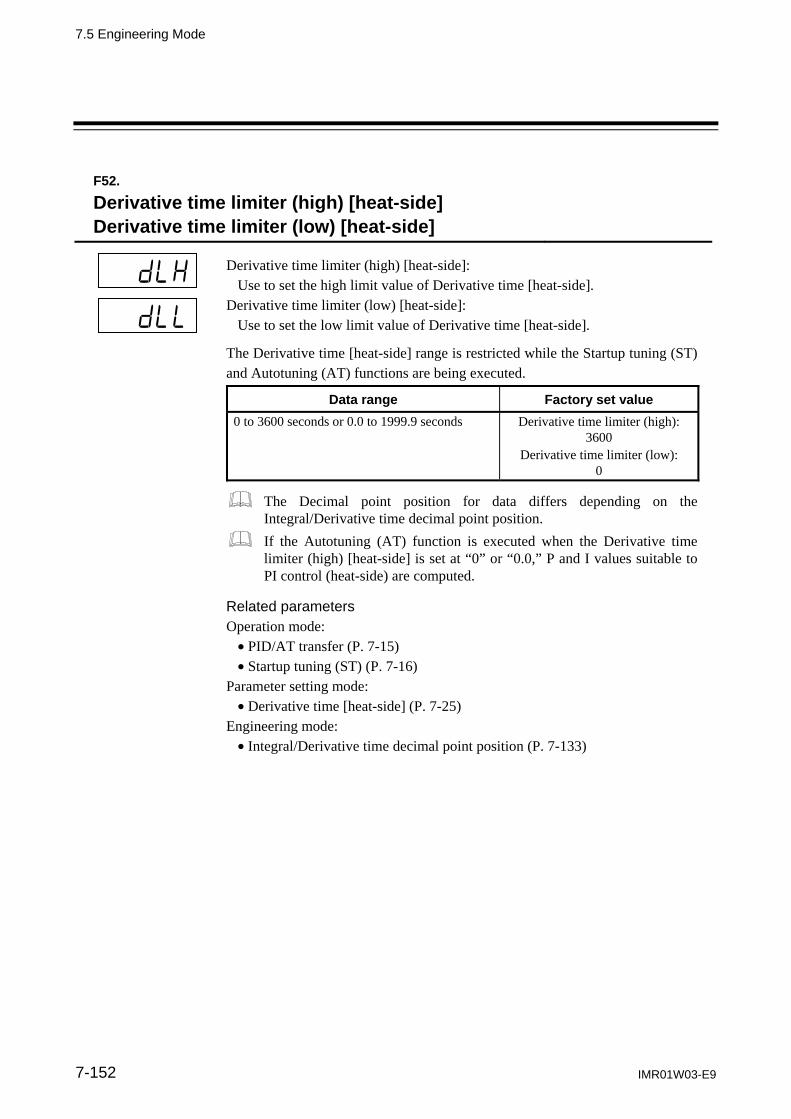
7.5 Engineering Mode
IMR01W03-E9 7-152
F52.
Derivative time limiter (high) [heat-side] Derivative time limiter (low) [heat-side]
Derivative time limiter (high) [heat-side]: Use to set the high limit value of Derivative time [heat-side].
Derivative time limiter (low) [heat-side]: Use to set the low limit value of Derivative time [heat-side].
The Derivative time [heat-side] range is restricted while the Startup tuning (ST) and Autotuning (AT) functions are being executed.
Data range Factory set value
0 to 3600 seconds or 0.0 to 1999.9 seconds Derivative time limiter (high): 3600
Derivative time limiter (low): 0
The Decimal point position for data differs depending on the Integral/Derivative time decimal point position.
If the Autotuning (AT) function is executed when the Derivative time limiter (high) [heat-side] is set at “0” or “0.0,” P and I values suitable to PI control (heat-side) are computed.
Related parameters Operation mode: PID/AT transfer (P. 7-15) Startup tuning (ST) (P. 7-16)
Parameter setting mode: Derivative time [heat-side] (P. 7-25)
Engineering mode: Integral/Derivative time decimal point position (P. 7-133)

7.5 Engineering Mode
IMR01W03-E9 7-153
F52.
Proportional band limiter (high) [cool-side] Proportional band limiter (low) [cool-side]
Proportional band limiter (high) [cool-side]: Use to set the high limit value of Proportional band [cool-side].
Proportional band limiter (low) [cool-side]: Use to set the low limit value of Proportional band [cool-side].
The Proportional band [cool-side] range is restricted while the Autotuning (AT) function is being executed.
Data range Factory set value
TC/RTD inputs: 1 (0.1, 0.01) to Input span (Unit: C [F]) Varies with the setting of the Decimal point position(P. 7-71).
Proportional band limiter (high):Input span
Proportional band limiter (low): 1 (0.1, 0.01)
Voltage (V)/Current (I) inputs: 0.1 to 1000.0 % of input span
Proportional band limiter (high):1000.0 %
Proportional band limiter (low): 0.1 %
The Proportional band limiter (high) [cool-side] and Proportional band limiter (low) [cool-side] are valid only during Heat/Cool PID control.
Related parameters Operation mode: PID/AT transfer (P. 7-15)
Parameter setting mode: Proportional band [cool-side] (P. 7-27)
Engineering mode: Decimal point position (P. 7-71)

7.5 Engineering Mode
IMR01W03-E9 7-154
F52.
Integral time limiter (high) [cool-side] Integral time limiter (low) [cool-side]
Integral time limiter (high) [cool-side]: Use to set the high limit value of Integral time [cool-side].
Integral time limiter (low) [cool-side]: Use to set the low limit value of Integral time [cool-side].
The Integral time [cool-side] range is restricted while the Autotuning (AT) function is being executed.
Data range Factory set value
0 to 3600 seconds or 0.0 to 1999.9 seconds Integral time limiter (high): 3600
Integral time limiter (low): 0
The Decimal point position for data differs depending on the Integral/Derivative time decimal point position.
If the Autotuning (AT) function is executed when the Integral time limiter (high) [cool-side] is set at “0” or “0.0,” P and D values suitable to PD control (cool-side) are computed.
The Integral time limiter (high) [cool-side] and Integral time limiter (low) [cool-side] are valid only during Heat/Cool PID control.
Related parameters Operation mode: PID/AT transfer (P. 7-15)
Parameter setting mode: Integral time [cool-side] (P. 7-27)
Engineering mode: Integral/Derivative time decimal point position (P. 7-133)

7.5 Engineering Mode
IMR01W03-E9 7-155
F52.
Derivative time limiter (high) [cool-side] Derivative time limiter (low) [cool-side]
Derivative time limiter (high) [cool-side]: Use to set the high limit value of Derivative time [cool-side].
Derivative time limiter (low) [cool-side]: Use to set the low limit value of Derivative time [cool-side].
The Derivative time [cool-side] range is restricted while the Autotuning (AT) function is being executed.
Data range Factory set value
0 to 3600 seconds or 0.0 to 1999.9 seconds Derivative time limiter (high): 3600
Derivative time limiter (low): 0
The Decimal point position for data differs depending on the Integral/Derivative time decimal point position.
If the Autotuning (AT) function is executed when the Derivative time limiter (high) [cool-side] is set at “0” or “0.0,” P and I values suitable to PI control (cool-side) are computed.
The Derivative time limiter (high) [cool-side] and Derivative time limiter (low) [cool-side] are valid only during Heat/Cool PID control.
Related parameters Operation mode: PID/AT transfer (P. 7-15)
Parameter setting mode: Derivative time [cool-side] (P. 7-28)
Engineering mode: Integral/Derivative time decimal point position (P. 7-133)

7.5 Engineering Mode
IMR01W03-E9 7-156
F52.
Proportional band adjusting factor [heat-side] Proportional band adjusting factor [cool-side]
Proportional band adjusting factor [heat-side]: This is a factor which is multiplied by the Proportional band [heat-side] computed by executing the Autotuning (AT) function.
Proportional band adjusting factor [cool-side]: This is a factor which is multiplied by the Proportional band [cool-side] computed by executing the Autotuning (AT) function.
Data range Factory set value
0.01 to 10.00 times 1.00
The Proportional band adjusting factor [cool-side] is valid only during Heat/Cool PID control.
Related parameters Operation mode: PID/AT transfer (P. 7-15)
Parameter setting mode: Proportional band [heat-side] (P. 7-24) Proportional band [cool-side] (P. 7-27)
F52.
Integral time adjusting factor [heat-side] Integral time adjusting factor [cool-side]
Integral time adjusting factor [heat-side]: This is a factor which is multiplied by the Integral time [heat-side] computed by executing the Autotuning (AT) function.
Integral time adjusting factor [cool-side]: This is a factor which is multiplied by the Integral time [cool-side] computed by executing the Autotuning (AT) function.
Data range Factory set value
0.01 to 10.00 times 1.00
The Integral time adjusting factor [cool-side] is valid only during Heat/Cool PID control.
Related parameters Operation mode: PID/AT transfer (P. 7-15)
Parameter setting mode: Integral time [heat-side] (P. 7-25) Integral time [cool-side] (P. 7-27)

7.5 Engineering Mode
IMR01W03-E9 7-157
F52.
Derivative time adjusting factor [heat-side] Derivative time adjusting factor [cool-side]
Derivative time adjusting factor [heat-side]: This is a factor which is multiplied by the Derivative time [heat-side] computed by executing the Autotuning (AT) function.
Derivative time adjusting factor [cool-side]: This is a factor which is multiplied by the Derivative time [cool-side] computed by executing the Autotuning (AT) function.
Data range Factory set value
0.01 to 10.00 times 1.00
The Derivative time adjusting factor [cool-side] is valid only during Heat/Cool PID control.
Related parameters Operation mode: PID/AT transfer (P. 7-15)
Parameter setting mode: Derivative time [heat-side] (P. 7-25) Derivative time [cool-side] (P. 7-28)
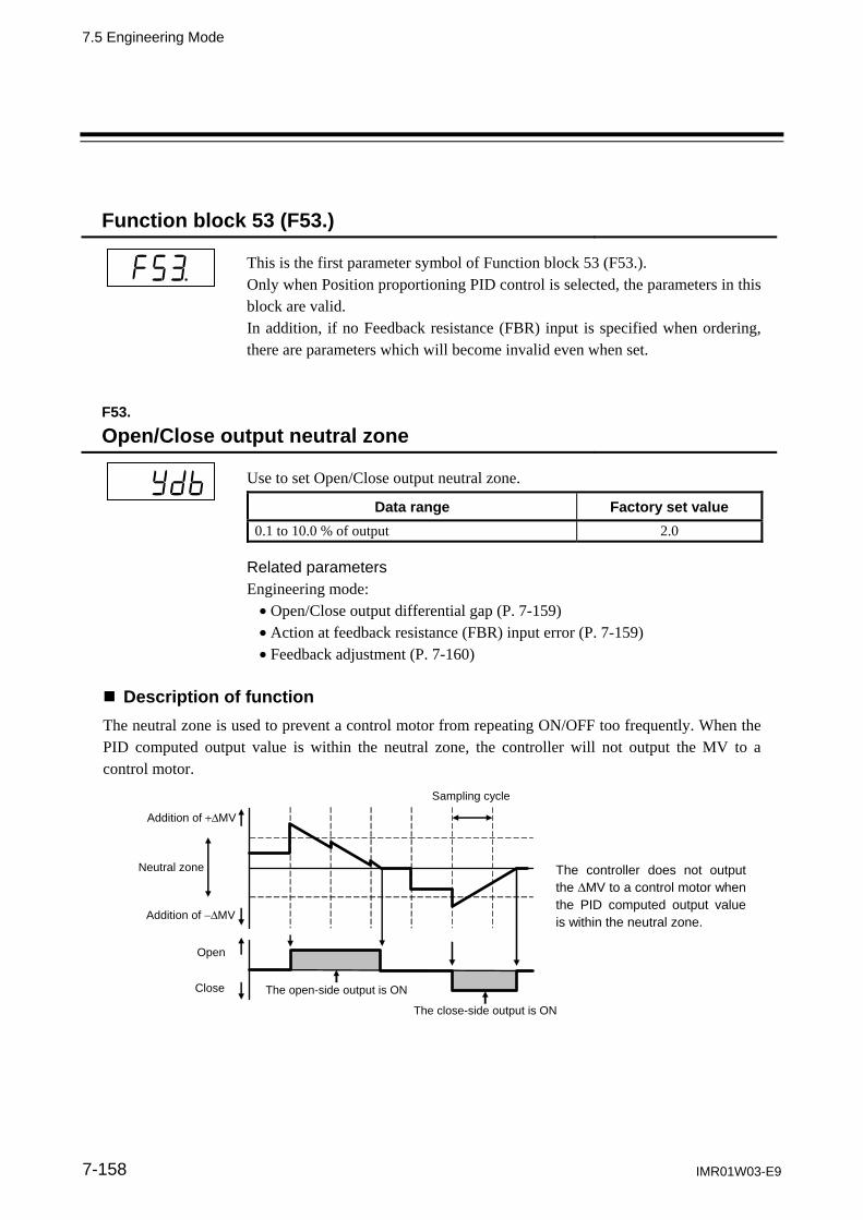
7.5 Engineering Mode
IMR01W03-E9 7-158
Function block 53 (F53.)
This is the first parameter symbol of Function block 53 (F53.). Only when Position proportioning PID control is selected, the parameters in this block are valid. In addition, if no Feedback resistance (FBR) input is specified when ordering, there are parameters which will become invalid even when set.
F53.
Open/Close output neutral zone
Use to set Open/Close output neutral zone.
Data range Factory set value
0.1 to 10.0 % of output 2.0
Related parameters Engineering mode: Open/Close output differential gap (P. 7-159) Action at feedback resistance (FBR) input error (P. 7-159) Feedback adjustment (P. 7-160)
Description of function
The neutral zone is used to prevent a control motor from repeating ON/OFF too frequently. When the PID computed output value is within the neutral zone, the controller will not output the MV to a control motor.
Addition of MV
Addition of MV
Neutral zone
Open
Close
The controller does not output the MV to a control motor when the PID computed output value is within the neutral zone.
Sampling cycle
The close-side output is ON
The open-side output is ON

7.5 Engineering Mode
IMR01W03-E9 7-159
F53.
Open/Close output differential gap
Use to set differential gap of Open/Close output used in the Position proportioning PID control.
Data range Factory set value
0.1 to 5.0 % of output 1.0
Related parameters Engineering mode: Open/Close output neutral zone (P. 7-158) Action at feedback resistance (FBR) input error (P. 7-159) Feedback adjustment (P. 7-160)
Description of function
The Open/Close output differential gap prevents output ON/OFF chattering caused by fluctuation of feedback resistance input.
ON
ON OFF
OFF
MV1
Open side
Close side
Neutral zone
Differential gap of Open/Close output
MV1: Manipulated output value
F53.
Action at Feedback resistance (FBR) input error FBR
input
OPTION
Use to select an action at the Feedback resistance (FBR) input break.
Data range Factory set value
0: Action depending on the value action at STOP 1: Control action continued
0
Related parameters Engineering mode: Open/Close output neutral zone (P. 7-158) Open/Close output differential gap (P. 7-159) Feedback adjustment (P. 7-160) Valve action at STOP (P. 7-162)

7.5 Engineering Mode
IMR01W03-E9 7-160
F53.
Feedback adjustment FBR
input
OPTION
Feedback adjustment function is to adjust controller’s output value to match the Feedback resistance (FBR) of the control motor. After the adjustment, the Manipulated output value of 0 to 100 % obtained after PID computation matches the valve position signal of the fully closed position to the fully opened position [Feedback resistance (FBR) input] sent from the control motor. The adjustment have to be completed before starting operation. Always make sure that the wiring is correct and the control motor operates normally before the adjustment. (Refer to P. 7-130) In addition, if opening adjustment is performed, the control motor time is automatically computed. However, if the time thus computed is less than 5 seconds, no set value is updated.
Data range Factory set value
0 (AdJ): Adjustment end 1 (oPn): During adjustment on the open-side 2 (CLS): During adjustment on the close-side
Adjustment procedure
At the Adjustment preparation screen, press the shift key for 5 seconds to start the adjustment. The display automatically returns to the Adjustment Preparation screen after the adjustment is completed.
Adjustment preparation screen
Press the shift key for 5 seconds.
Automatically
Automatically
Adjustment screen for open direction.
Adjustment screen for close direction.
(Adjustment end)
Display returns to the PV/SV monitor screen if no key operation is performed within 1 minute (except during the feedback adjustment).

7.5 Engineering Mode
IMR01W03-E9 7-161
F53.
Control motor time FBR
input
OPTION
This is the time required until the control motor is fully opened from its fully closed state.
Data range Factory set value
5 to 1000 seconds 10
If opening adjustment is performed, the Control motor time is automatically computed. However, if the time thus computed is less than 5 seconds, no set value is updated.
Related parameter Engineering mode: Integrated output limiter (P. 7-161)
F53.
Integrated output limiter
This is a restricted value when the output on the open or closed side is integrated. If the output on the open (or closed) side is output in succession, it is integrated and if the result reaches the Integrated output limiter value, the output on the open (or closed) side is turned off. In addition, if the output on the open (or closed) side is reversed, the integrated value is reset.
Data range Factory set value
0.0 to 200.0 % of control motor time (0.0: Integrated output limiter function OFF)
150.0
The Integrated output limiter is invalid when the Feedback resistance (FBR) input was used.
Related parameter Engineering mode: Control motor time (P. 7-161)
Setting example
If control is started at the fully closed state when the control motor time is set at 10 seconds and the Integrated output limiter value is set at 100 %, the following results.
The output on the open-side is output for 5 seconds.
Open-side side integrated value: 80 %
STOP
The output on the close-side is output for 2 seconds, and the integrated output value of open- side is reset at once. Next, the output on the close-side starts being integrated. (New close-side integrated value becomes 20 %.)
The output on the open-side is output for 3 seconds.
Open-side side integrated value: 30 %
STOP

7.5 Engineering Mode
IMR01W03-E9 7-162
F53.
Valve action at STOP
Select the valve action when Feedback resistance (FBR) input is disabled or “0 (Action depending on the value action setting at STOP)” is set for the action when a Feedback resistance (FBR) input break occurs.
Data range Factory set value
0: Close-side output OFF, Open-side output OFF 1: Close-side output ON, Open-side output OFF 2: Close-side output OFF, Open-side output ON
0
Related parameter Engineering mode: Action at Feedback resistance (FBR) input error (P. 7-159)
F53.
Action at saturated output FBR
input
OPTION
Set to maintain ON state for the close-side (or open-side) output when the valve position is fully closed (or opened).
Data range Factory set value
0: Invalid (The close-side [or open-side] output turns to OFF when the valve position is fully closed [or opened]). 1: Valid (The close-side [or open-side] output remains ON state when the valve position is fully closed [or opened]).
0
Related parameter Engineering mode: Action at Feedback resistance (FBR) input error (P. 7-159)
Description of function
[When the Action at saturated output is invalid] The close-side output turns OFF when the valve position is fully closed (FBR input value 0 %). * The open-side output turns OFF when the valve position is fully opened (FBR input value 100 %). * [When the Action at saturated output is valid] The close-side output remains ON when the valve position is fully closed (FBR input value 0 %). * The open-side output remains ON when the valve position is fully opened (FBR input value 100 %). * * When controlling the valve position by Output limiter, the output limiter value becomes the close-side (or the
open-side) output value.
To validate the Action at saturated output, make sure to use valve with limit switch. Refer to the Action at Feedback resistance (FBR) input error for the valve action when the FBR input is broken.

7.5 Engineering Mode
IMR01W03-E9 7-163
Function block 54 (F54.)
This is the first parameter symbol of Function block 54 (F54.).
F54.
ST start condition
Timing (starting condition) to activate the Startup tuning (ST) function is selected.
Data range Factory set value
0: Activate the Startup tuning (ST) function when the power is turned on; when transferred from STOP to RUN; or when the Set value (SV) is changed.
1: Activate the Startup tuning (ST) function when the power is turned on; or when transferred from STOP to RUN.
2: Activate the Startup tuning (ST) function when the Set value (SV) is changed.
0
Related parameter Operation mode: Startup tuning (ST) (P. 7-16)
F54.
ST proportional band adjusting factor
This is a factor which is multiplied by the Proportional band computed by executing the Startup tuning (ST) function.
Data range Factory set value
0.01 to 10.00 times 1.00
Related parameter Operation mode: Startup tuning (ST) (P. 7-16)

7.5 Engineering Mode
IMR01W03-E9 7-164
F54.
ST integral time adjusting factor
This is a factor which is multiplied by the Integral time computed by executing the Startup tuning (ST) function.
Data range Factory set value
0.01 to 10.00 times 1.00
Related parameter Operation mode: Startup tuning (ST) (P. 7-16)
F54.
ST derivative time adjusting factor
This is a factor which is multiplied by the Drivative time computed by executing the Startup tuning (ST) function.
Data range Factory set value
0.01 to 10.00 times 1.00
Related parameter Operation mode: Startup tuning (ST) (P. 7-16)

7.5 Engineering Mode
IMR01W03-E9 7-165
Function block 55 (F55.)
This is the first parameter symbol of Function block 55 (F55.).
F55.
Automatic temperature rise group Commu-
nication
OPTION
Group No. when conducting an Automatic temperature rise. Controllers with the same group numbers are collected in one group and the temperature is risen by other controllers so that they will synchronize with a controller whose temperature rise is slowest in that group.
Data range Factory set value
0 to 16 (0: Automatic temperature rise function OFF)
0
The Automatic temperature rise function via Intercontroller communication is executed when the Communication 2 port is ready to be used and the Communication 2 protocol (CMP2) is set to “2: Intercontroller communication.”
If the group RUN/STOP function via Intercontroller communication is used, all of the controllers in one group can simultaneously start rising the temperature.
For the Automatic temperature rise, refer to 6.14.4 Automatic temperature rise function [with learning function] (P. 6-72).
Related parameters Operation mode: Automatic temperature rise learning (P. 7-17)
Engineering mode: RUN/STOP group (P. 7-166) Automatic temperature rise dead time (P. 7-167) Automatic temperature rise gradient data (P. 7-167) Communication 2 protocol (P. 7-168)

7.5 Engineering Mode
IMR01W03-E9 7-166
F55.
RUN/STOP group Commu-
nication
OPTION
Group No. when RUN/STOP transfer is made for each group. Controllers with the same group numbers are collected in one group and RUN/STOP transfer is made for each group.
Data range Factory set value
0 to 16 (0: RUN/STOP group function OFF) 0
The group RUN/STOP function via Intercontroller communication is executed when the Communication 2 port is ready to be used and the Communication 2 protocol (CMP2) is set to “2: Intercontroller communication.”
If even one controller in the same group is set to STOP (control stop) by Key operation, Communication or Digital input (DI), STOP (control stop) results.
If even one controller in the same group is set to RUN (control start) by Key operation, Communication or Digital input (DI), RUN (control start) results. However, no RUN results if there is even one controller whose Digital input (DI) is set to STOP.
If the group RUN/STOP function is used when an Automatic temperature rise via Intercontroller communication is made, all of the controllers in one group can simultaneously start rising the temperature.
For selecting group RUN/STOP, refer to 6.14.3 Group RUN/STOP function (P. 6-63).
Related parameters Operation mode: RUN/STOP transfer (P. 7-18)
Engineering mode: Automatic temperature rise group (P. 7-165) Communication 2 protocol (P. 7-168)

7.5 Engineering Mode
IMR01W03-E9 7-167
F55.
Automatic temperature rise dead time
Control response dead time of a controlled object. It is computed by Automatic temperature rise learning.
Data range Factory set value
0.1 to 1999.9 seconds 10.0
The Automatic temperature rise dead time is also computed when the Startup tuning (ST) function [only when power is turned on] is executed.
For the Automatic temperature rise, refer to 6.14.4 Automatic temperature rise function [with learning function] (P. 6-72).
Related parameters Operation mode: Startup tuning (ST) (P. 7-16) Automatic temperature rise learning (P. 7-17)
Engineering mode: Automatic temperature rise group (P. 7-165) Automatic temperature rise gradient data (P. 7-167)
F55.
Automatic temperature rise gradient data
This parameter is used to set the temperature change per one minute when the Automatic temperature rise is performed. It is computed by Automatic temperature rise learning.
Data range Factory set value
0.1 to Input span/minutes 1.0
The Automatic temperature rise gradient data is also computed when the Startup tuning (ST) function [only when power is turned on] is executed.
For the Automatic temperature rise, refer to 6.14.4 Automatic temperature rise function [with learning function] (P. 6-72).
Related parameters Operation mode: Startup tuning (ST) (P. 7-16) Automatic temperature rise learning (P. 7-17)
Engineering mode: Automatic temperature rise group (P. 7-165) Automatic temperature rise dead time (P. 7-167)
7.5 Engineering Mode
IMR01W03-E9 168
Function block 60 (F60.)
This is the first parameter symbol of Function block 60 (F60.). The settings of parameters in this block become valid on the controller with the Communication function (optional).
F60.
Communication 1 protocol Communication 2 protocol
Commu-nication
OPTION
Communication 1 protocol: Use to select the protocol for Communication 1 function.
Communication 2 protocol: Use to select the protocol for Communication 2 function.
Data range Factory set value
Communication 1 protocol: 0: RKC communication 1: Modbus
0
If the Communication 1 protocol is specified by the model and suffix code when ordering, that Communication 1 protocol becomes the factory set value.
Communication 2 protocol: 0: RKC communication 1: Modbus 2: Intercontroller communication
2
For the Intercontroller communication, refer to 6.14 Group operation by the Intercontroller communication (P. 6-60).
For the Communication function, refer to the separate FB100/FB400/ FB900 Communication Instruction Manual (IMR01W04-E).
Related parameters Setup setting mode: Device address 1, Device address 2 (P. 7-44) Communication speed 1, Communication speed 2 (P. 7-44) Data bit configuration 1, Data bit configuration 2 (P. 7-45) Interval time 1, Interval time 2 (P. 7-46)
Engineering mode: External input type (P. 7-125) Automatic temperature rise group (P. 7-165) RUN/STOP group (P. 7-166)

7.5 Engineering Mode
IMR01W03-E9 7-169
Function block 70 (F70.)
This is the first parameter symbol of Function block 70 (F70.).
F70.
Setting change rate limiter unit time
Set the time unit for Setting change rate limiter (up/down).
Data range Factory set value
1 to 3600 seconds 60
Related parameter Parameter setting mode: Setting change rate limiter (up), Setting change rate limiter (down) (P. 7-31)
F70.
Soak time unit
Use to select the time unit for Area soak time.
Data range Factory set value
0: 0 hours 00 minutes to 99 hours 59 minutes 1: 0 minutes 00 seconds to 199 minutes 59 seconds
1
Related parameter Parameter setting mode: Area soak time (P. 7-32)

7.5 Engineering Mode
IMR01W03-E9 7-170
Function block 71 (F71.)
This is the first parameter symbol of Function block 71 (F71.).
F71.
Setting limiter high Setting limiter low
Setting limiter high: Use to set a high limit of the set value. Setting limiter low: Use to set a low limit of the set value.
Data range Factory set value
Setting limiter high: Setting limiter low to Input scale high Varies with the setting of the Decimal point position (P. 7-71).
Input scale high
Setting limiter low: Input scale low to Setting limiter high Varies with the setting of the Decimal point position (P. 7-71).
Input scale low
Related parameters Engineering mode: Decimal point position (P. 7-71) Input scale high, Input scale low (P. 7-72)
Description of function
Setting limiter is to set the range of the Set value (SV).
[Example] The input range (input scale range) is from 0 to 400 C, the Setting limiter high is 200 C, and the Setting limiter low is 20 C.
Setting range
0 C 20 C Setting limiter low
400 C 200 C Setting limiter high
7.5 Engineering Mode
IMR01W03-E9 7-171
Function block 91 (F91.)
This is the first parameter symbol of Function block 91 (F91.).
F91.
ROM version monitor
Displays the version of loaded software.
Display range Factory set value
Version of ROM built in the controller
F91.
Integrated operating time monitor
Displays the integrated total operating time of the controller.
Display range Factory set value
0 to 19999 hours

7.5 Engineering Mode
IMR01W03-E9 7-172
F91.
Holding peak value ambient temperature monitor
Displays the maximum ambient temperature of the instrument.
Display range Factory set value
10.0 to 100.0 C
F91.
Power feed forward input value monitor PFF
input
OPTION
Displays the input value of a power feed transformer.
Display range Factory set value
0.0 to 160.0 % Display in the percentage of the load voltage (rated value).
Related parameters Engineering mode: Power feed forward selection (P. 7-140) Power feed forward gain (P. 7-141)
Display returns to the PV/SV monitor screen if no key operation is performed within 1 minute (except during the Power feed forward input value monitor display).

TROUBLESHOOTING
IMR01W03-E9 8-1
8.1 Error Display ..................................................................................... 8-2
8.2 Solutions for Problems ...................................................................... 8-4

8. TROUBLESHOOTING
8-2 IMR01W03-E9
8.1 Error Display
This Section describes error display when the Measured value (PV) exceeds the display range and the self-diagnostic error. Display when input error occurs
The table below shows displays, description, control actions and solutions when the Measured value (PV) exceeds the display range.
Prior to replacing the sensor, always turn OFF the power or change to STOP with RUN/STOP transfer.
Display Description Action (Output) Solution
Measured value (PV) [Flashing]
Measured value (PV) exceeds the Input scale high/low. Measured value (PV) exceeds the
Input error determination point (high/low limit).
Action at input error: Output depending on the action at Input error (high/low limit) [Refer to page 7-135.]
Event output: Output depending on the event action at input error
Check input type, input range, sensor and sensor connection.
[Flashing]
Over-scale Measured value (PV) is above the display range limit high (or 19999).
[Flashing]
Underscale Measured value (PV) is below the display range limit low (or 19999).
Input error determination point (high)
Input range (Input span)
Display range limit
Measured value (PV) flashing *
Event status at input error
Measured value (PV) display
Event
Input error determination point(low)
Measuredvalue (PV) flashing * Over-scaleUnderscale
Event status at input error
5 % of input span
Action area at input error Action area at input error
5 % of input span
Input scale low Input scale high
Manipulated output at input error
Chooses either
Present output
Manipulated output (MV)
Manipulated output at input error
Chooses either
Present output
* "Flashing display" or "Non-flashing display" of PV can be selected for the PV flashing display at input error of the Engineering Mode (F10).
Auto modeManipulated output value (MV)obtained by PID control
Manual mode Manipulated output value (MV) at manual setting

8.1 Error Displays
IMR01W03-E9 8-3
Self-diagnostic error
In an error is detected by the Self-diagnostic function, the PV display shows “Err,” and the SV display shows the error code. If two or more errors occur simultaneously, the total summation of these error code is displayed.
Error number
Description Action Solution
1 Adjusted data error Adjusted data range is
abnormal.
Display: Error display (Err)
Output: All the output is OFF (Same as the power off)
Communication: Possible
Turn off the power at once.
If the FB400/900 is restored to normal after the power is turned on again, then probable cause may be external noise source affecting the control system. Check for the external noise source.
If an error occurs after the power is turned on again, the FB400/900 must be repaired or replaced. Please contact RKC sales office or the agent.
2 Back-up error Back-up action is abnormal. Data write failure
4 A/D conversion error Response signal from A/D
converter is abnormal.
32 Custom data error There is an abnormality on
download data and it cannot execute.
128 Watchdog timer error The part of an internal
program stops the action.
256 Stack overflow Stack area of stack pointer
overflows
2048 Program error (busy) Could not finish an internal
program in a specified time.
If any of the following error occurs, all action of the FB400/900 is stopped. In this case, the error number is not displayed.
Description Action Solution
Power supply voltage is abnormal (power supply voltage monitoring)
Display: All display is OFF Output: All output is OFF
The FB400/900 must be repaired or replaced.
Please contact RKC sales office or the agent.
RAM error (RAM check) Communication: No response
<Example of error display>

8. TROUBLESHOOTING
8-4 IMR01W03-E9
8.2 Solutions for Problems
This section explains possible causes and solutions if any abnormality occurs in the instrument. For any inquiries or to confirm the specifications of the product, please contact RKC sales office or the agent. If it is necessary to replace a device, always strictly observe the warnings below.
All wiring must be completed before power is turned on to prevent electric shock, instrument failure, or incorrect action. The power must be turned off before repairing work for input break and output failure including replacement of sensor, contactor or SSR, and all wiring must be completed before power is turned on again.
To prevent electric shock or instrument failure, always turn off the system
power before replacing the instrument.
To prevent electric shock or instrument failure, always turn off the power before mounting or removing the instrument.
To prevent electric shock or instrument failure, do not turn on the power until all wiring is completed. Make sure that the wiring is correct before applying power to the instrument.
To prevent electric shock or instrument failure, do not touch the inside of the instrument.
All wiring must be performed by authorized personnel with electrical experience in this type of work.
WARNING!
CAUTION

8.2 Solutions for Problems
IMR01W03-E9 8-5
Display
Problem Possible cause Solution
No display appears The internal assembly is not inserted into the case correctly.
Insert the internal assembly into the case correctly.
Power supply terminal connection not correct.
Connect the terminals correctly by referring to 4.3 Wiring of Each Terminal (P. 4-6).
Power supply terminal contact defect.
Retighten the terminals
The proper power supply voltage is not being supplied.
Apply the normal power supply by referring to 9. SPECIFICATIONS (P. 9-1).
Display is abnormal Noise source is present near the instrument.
Separate the noise source from the instrument. Set the appropriate digital filter according to the responding control systems.
The terminal board on the instrument using the thermocouple is directly exposed to the air from an air conditioner.
Do not directly expose the terminal board to the air from the air conditioner.
Remote setting signal input is in parallel to two or more this instruments which use grounding type thermocouples.
Insert an isolator to enable isolated remote setting signal input for each instrument.
Measured value (PV) display differs from the actual value
Proper sensor is not used. Use the specified sensor. The PV bias is set. Set the PV bias to “OFF” by
referring to PV bias (P. 7-40). However, this is limited only to when the PV bias setting can be changed.
The PV ratio is set. Change the PV ratio setting by referring to PV ratio (P. 7-40). However, this is limited only to when the PV ratio setting can be changed.
Display value fluctuates Setting of measured input sampling cycle is not appropriate. (Factory set value: 100 ms)
Set the appropriate sampling cycle by referring to Sampling cycle (P. 7-76). However, this is limited only to when the sampling cycle setting can be changed.
How to check if the input function of the controller is working correctly. When the controller is configured as Thermocouple input:
Short the input terminals No. 23 and No. 24. If the controller shows a Measured value around the ambient temperature of the input terminals, the input function of the controller is working correctly.
When the controller is configured as RTD input: Connect a 100 resister between the input terminals No. 22 and No. 23 and short the input terminals No. 23 and No. 24. If the controller shows Measured value around 0 C (32 F), the input function of the controller is working correctly.
When the controller is configured as Voltage/Current input: Input a certain voltage or current from a voltage/current generator to the controller. If the controller shows the equivalent input value, the input setting and function of the controller is working correctly.

8.2 Solutions for Problems
IMR01W03-E9 8-6
Control
Problem Possible cause Solution
Control is abnormal The proper power supply voltage is not being supplied.
Apply the normal power supply by referring to 9. SPECIFICATIONS (P. 9-1).
Break of sensor and input lead wires
Turn off the power or STOP the operation by “RUN/STOP transfer” and repair the sensor or replace it.
Sensor wiring improperly conducted
Conduct sensor wiring correctly by referring to 4.3 Wiring of Each Terminal (P. 4-6).
Proper sensor is not used. Use the specified sensor.
Sensor insertion depth is insufficient.
Check whether sensor is inserted loosely. If yes, fully insert the sensor.
Sensor insertion position is not appropriate.
Insert the sensor at the specified location.
Input signal wires are not separated from instrument power and/or load wires.
Separate each wire.
Noise source is present near the wiring.
Separate the noise source from the wiring.
Inappropriate PID constants Set the appropriate PID constants.
Startup tuning (ST) function cannot be activated
Startup tuning (ST) mode is “oFF.” (Factory set value: oFF)
Refer to 6.6 Startup Tuning (ST) (P. 6-18).
Requirements for performing the Startup tuning (ST) function are not satisfied.
Satisfy the requirements for performing the Startup tuning (ST) function by referring to
6.6 Startup Tuning (ST) (P. 6-18).
Autotuning (AT) function not activated
Requirements for performing the Autotuning (AT) function are not satisfied.
Satisfy the requirements for performing the Autotuning (AT) function by referring to 6.5 Autotuning (AT) (P. 6-15).
Autotuning (AT) suspended Requirements for suspending the Autotuning (AT) function are established.
Identify causes for Autotuning (AT) suspension by referring to 6.5 Autotuning (AT) (P. 6-15) and then remove them. Then, execute the Autotuning (AT) function again.
Continued on the next page.

8.2 Solutions for Problems
IMR01W03-E9 8-7
Continued from the previous page.
Problem Possible cause Solution
Acceptable PID values can not be computed by Autotuning (AT)
The Autotuning (AT) function does not appropriately much the characteristics of the controlled object.
Set PID constants manually.
The output change rate limiter is set.
Set PID constants manually.
Set the Output change rate limiter to “0.0: OFF” by referring to Output change rate limiter (up/down) (P. 7-137). However, this is limited only to when the Output change rate limiter setting can be changed.
Autotuning (AT) cannot be finished normally
A temperature change (UP and/or Down) is 1 C or less per minute during Autotuning.
Set PID constants manually.
Autotuning (AT) is activated when the set value is around the ambient temperature or is close to the maximum temperature achieved by the load.
No output change in step The output change rate limiter is set.
Set the Output change rate limiter to “0.0: OFF” by referring to Output change rate limiter (up/down) (P. 7-137). However, this is limited only to when the Output change rate limiter setting can be changed.
Output does not become more than (or less than) a specific value
The output limiter is set. Change the Output limiter setting by referring to Output limiter (high/low) (P. 7-138). However, this is limited only to when the Output limiter setting can be changed.

8.2 Solutions for Problems
IMR01W03-E9 8-8
Operation
Problem Possible cause Solution
No control RUN can be made by key operation (Digital input: Only DI5)
RUN/STOP transfer of the Digital input (DI) is set to the contact opened.
Check the contact state of RUN/STOP transfer by referring to 6.4 RUN/STOP Transfer (P. 6-11).
No Manual mode can be made by key operation. (Digital input: any of DI5 to DI7)
Auto/Manual transfer of the Digital input (DI) is set to the contact opened.
Check the contact state of Auto/Manual transfer by referring to 6.7 Auto/Manual Transfer (P. 6-23).
No Remote mode can be made by key operation (Digital input: either DI5 or DI6)
Remote/Local transfer of the Digital input (DI) is set to the contact opened.
Check the contact state of Remote/Local transfer by referring to 6.8 Remote/Local Transfer (P. 6-28).
No control area transfer can be made by key operation Digital input (DI1 to DI3): Area transfer Digital input (DI4): Area set
Control area transfer of the Digital input (DI) is set to the contact opened.
Check the contact state of control area transfer by referring to 6.9 Control Area Transfer (P. 6-32).
No setting change can be made by key operation
Set data is locked. Release the Set data lock by referring to Set lock level (P. 7-47).
Set value (SV) does not become more than (or less than) a specific value
The Setting limiter is set Change the Setting limiter setting by referring to Setting limiter high/low (P. 7-170). However, this is limited only to when the Setting limiter setting can be changed.
Set value (SV) does not change immediately when the set value (SV) is changed
The Setting change rate limiter is set.
Set the Setting change rate limiter to “OFF” by referring to Setting change rate limiter (up/down) (P. 7-31). However, this is limited only to when the Setting limiter setting can be changed.
Remote setting (RS) input value display differs from the actual value
The RS bias is set. Set the RS bias to “OFF” by referring to RS bias (P. 7-42). However, this is limited only to when the RS bias setting can be changed.
The RS ratio is set. Change the RS ratio setting by referring to RS ratio (P. 7-42). However, this is limited only to when the RS ratio setting can be changed.

8.2 Solutions for Problems
IMR01W03-E9 8-9
Event function
Problem Possible cause Solution
Event function is abnormal Event function is different from the specification.
Change the Event action type by referring to Event 1 type (P. 7-85), Event 2 type (P. 7-95), Event 3 type (P. 7-102), or Event 4 type (P. 7-109) after the instrument specification is confirmed.
Digital output (DO) relay contact Energized/De-energized is reversed. When FAIL is selected for digital output: De-energized fixed: Contact opens under
FAIL
Check the setting details by referring to Energized/De-energized (P. 7-80).
Setting of Event differential gap is not appropriate.
Set the appropriate Event differential gap by referring to Event differential gap (P. 7-90, P. 7-99, P. 7-106, P. 7-113).
No output of the Event function is turned on
Event function is not assigned to the Digital output (DO).
Check the contents of Output assignment by referring to Output assignment (P. 7-79).
Event hold action is not activated. The Setting change rate limiter is set.
Set the Setting change rate limiter to “OFF” by referring to Setting change rate limiter (up/down) (P. 7-31). However, this is limited only to when the Setting limiter setting can be changed.

8.2 Solutions for Problems
IMR01W03-E9 8-10
Heater break alarm (HBA)
Problem Possible cause Solution
No Heater break can be detected Setting of Heater break alarm is not appropriate.
Set the appropriate Heater break alarm value.
The CT is not connected. Connect the CT by referring to 4.3 Wiring of Each Terminal (P. 4-6).
CT input value is abnormal Proper CT is not used. Use the specified CT.
The heater is broken. Check the heater.
CT wiring improperly conducted Conduct CT wiring correctly by referring to 4.3 Wiring of Each Terminal (P. 4-6).
Input terminal contact defect Retighten the terminals

SPECIFICATIONS
IMR01W03-E9 9-1
1.1 ******** .............................................................................................. 1-2
1.2 ******* ................................................................................................ 1-3
1.3 ****** ................................................................................................. 1-4
1.4 *********** .......................................................................................... 1-5 1.4.1 ***** ...................................................................................................... 1-6 1.4.2 ******** .................................................................................................. 1-7

9. SPECIFICATIONS
9-2 IMR01W03-E9
Measured input
Number of input: 1 point
Input type: Temperature, Current and Voltage (low) group * Thermocouple (TC): K, J, T, S, R, E, B, N (JIS-C1602-1995) PL II (NBS), W5Re/W26Re (ASTM-E988-96) U, L (DIN43710-1985) RTD: Pt100 (JIS-C1604-1997) JPt100 (JIS-C1604-1997, JIS-C1604-1981 of Pt100) 3-wire system Voltage: 0 to 10 mV DC, 10 to 10 mV DC, 0 to 100 mV DC, 100 to 100 mV DC, 0 to 1 V DC Current: 4 to 20 mA DC, 0 to 20 mA DC
Voltage (high) group * Voltage: 1 to 1 V DC, 0 to 5 V DC, 1 to 5 V DC, 0 to 10 V DC * Universal input (Use the input select switch to change input group.)
Input range: TC input
RTD input
Input type Measured range
Pt100 −100.00 to +100.00 C, −200.0 to +850.0 C, −199.99 to +199.99 F, −328.0 to +1562.0 F
JPt100 −100.00 to +100.00 C, −200.0 to +640.0 C, −199.99 to +199.99 F, −328.0 to +1184.0 F
Voltage/Current input
Input type Measured rangeVoltage (low) 0 to 10 mV DC, 10 to 10 mV DC,
0 to 100 mV DC, 100 to 100 mV DC 0 to 1 V DC
Programmable range
(19999 to 19999)Voltage (high) 1 to 1 V DC, 0 to 5 V DC,
1 to 5 V DC, 0 to 10 V DC
Current 0 to 20 mA DC, 4 to 20 mA DC Sampling cycle: 100 ms0.3 % (50 ms5 % or 250 ms0.3 % is selectable)
Input type Measured range
K −200.0 to +400.0 C, −200.0 to +800.0 C, −200 to +1372 C, −328.0 to +400.0 F, −250.0 to +800.0 F, −328 to +2502 F
J 0.0 to 400.0 C, −200.0 to +400.0 C, −200.0 to +800.0 C, −200 to +1200 C, −200.0 to +700.0 F, −328.0 to +1200.0 F, −328 to +2192 F
T −200.0 to +400.0 C, −328.0 to +752.0 F
S, R −50 to +1768 C, −58 to +3214 F
E −200.0 to +700.0 C, −200 to +1000 C, −328.0 to +1292.0 F, −328 to +1832 F
B 0 to 1800 C, 0 to 3272 F
N 0 to 1300 C, 0 to 2372 F
PLII 0 to 1390 C, 0 to 2534 F
W5Re/W26Re 0 to 2300 C, 0 to 4200 F
U 0.0 to 600.0 C, 32.0 to 1112.0 F L 0.0 to 900.0 C, 32.0 to 1652.0 F

9. SPECIFICATIONS
IMR01W03-E9 9-3
Influence of external resistance: Approx. 0.2 V/ (Converted depending on TC types)
Influence of input lead: Approx. 0.01 / of PV (RTD input) 10 or less per wire
Input impedance: TC input: 1 M or more Voltage (low) input: 1 M or more Voltage (high) input: Approx. 1 M Current input: Approx. 50
Sensor current: Approx. 250 A (RTD input) Action at input beak: TC input: Upscale or Downscale RTD input: Upscale Voltage (low) input: Upscale or Downscale Voltage (high) input: Downscale (Indicates value near 0 V) Current input: Downscale (Indicates value near 0 mA) Action at input short circuit: Downscale (RTD input) Action at input error: Setting range of Input error determination point (high/low): Input scale low − (5 % of input span) to Input scale high + (5 % of input span) High/Low individual setting Manipulated output value at input error: 105.0 to 105.0
Input correction: PV bias: Input span to Input span PV ratio: 0.500 to 1.500 First order lag digital filter: 0.0 to 100.0 seconds (0.0: OFF) Square root extraction function (Voltage input, Current input): Calculation method: Measured value = (Input value PV ratio + PV bias) PV low input cut-off: 0.00 to 25.00 % of input span
Remote setting (RS) input [provided as standard]
Number of input: 1 point (Not isolated from measured input) Input type: Voltage (low) input: 0 to 10 mV DC, 0 to 100 mV DC, 0 to 1 V DC Voltage (high) input: 0 to 5 V DC, 1 to 5 V DC, 0 to 10 V DC Current input: 0 to 20 mA DC, 4 to 20 mA DC Sampling cycle: 200 ms (twice of the measured input sampling cycle) 100 ms (twice of the measured input sampling cycle) 500 ms (twice of the measured input sampling cycle)
Input impedance: Voltage (low) input: 1 M or more Voltage (high) input: Approx. 1 M Current input: Approx. 50 Action at input beak: Voltage input: Downscale (Indicates value near 0 V) Current input: Downscale (Indicates value near 0 mA)
Input correction: RS bias: Input span to Input span RS ratio: 0.001 to 9.999 RS digital filter (first order lag): 0.0 to 100.0 seconds (0.0: OFF)
Allowable input voltage: Voltage (low) input: Within 3.5 V Voltage (high) input: Within 12 V

9. SPECIFICATIONS
IMR01W03-E9 9-4
Current transformer (CT) input [optional]
Number of inputs: 2 points (when PFF input is selected: 1 point)
CT type: CTL-6-P-N or CTL-12-S56-10-N (Sold separately)
Input range: CTL-6-P-N: 0.0 to 30.0 A CTL-12-S56-10L-N: 0.0 to 100.0 A
Sampling cycle: 200 ms (twice of the measured input sampling cycle) 100 ms (twice of the measured input sampling cycle) 500 ms (twice of the measured input sampling cycle)
CT ratio: 0 to 9999 CTL-6-P-N: 800 CTL-12-S56-10L-N: 1000
Automatic power frequency detection: Power frequency can be set by automatic detection. However, no frequency may be able to be detected if at a CT value of less than 0.5 A. Feedback resistance (FBR) input [optional] Number of input: 1 point
Permissible resistance range: 100 to 10 k (Standard: 135 )
Input range: 0.0 to 100.0 (for adjustment span of open and close)
Sampling cycle: 200 ms (twice of the measured input sampling cycle) 100 ms (twice of the measured input sampling cycle) 500 ms (twice of the measured input sampling cycle)
Action at FBR break: Upscale
Power feed forward (PFF) input [optional]
Number of input: 1 point (Use the special transformer)
Allowable voltage range: Input of instrument: 0 to 20 V Load power supply voltage: 120 V AC transformer (PFT-01): 0 to 168 V AC 240 V AC transformer (PFT-02): 0 to 336 V AC
Sampling cycle: 200 ms (twice of the measured input sampling cycle) 100 ms (twice of the measured input sampling cycle) 500 ms (twice of the measured input sampling cycle)
Automatic power frequency detection: Power frequency can be set by automatic detection. Digital input (DI) Number of inputs: 7 points (4 points: DI1 to DI4 [optional], 3 points: DI5 to DI7)
Input method: Dry contact input Open state: 500 k or more Close state: 10 or less Contact current: 5 mA or less Voltage at open: Approx. 5 V DC
Capture judgment time: 200 ms

9. SPECIFICATIONS
IMR01W03-E9 9-5
Output (OUT1, OUT2)
Number of outputs: Up to 2 points (Output 1, Output 2)
Output contents: Used for control output or digital output (DO) (Specify when ordering)
Output type: Relay contact output Contact type: 1a contact Contact rating (Resistive load): 250 V AC 3 A, 30 V DC 1 A Electrical life: 300,000 times or more (Rated load) Mechanical life: 50 million times or more
(Switching: 180 times/min)
Voltage pulse output Output voltage: 0/12 V DC (Rating)
ON voltage: 11 V or more, 13 V or less OFF voltage: 0.2 V or less
Allowable load resistance: 600 or more
Current output Output current (Rating): 4 to 20 mA DC, 0 to 20 mA DC Output range: 1 to 21 mA DC, 0 to 21 mA DC Allowable load resistance: 600 or less Output impedance: 1 M or more
Voltage output Output voltage (Rating): 0 to 10 V DC, 0 to 5 V DC, 1 to 5 V DC Output range: 0.5 to 10.5 V DC, 0.25 to 5.25 V DC, 0.8 to 5.2 V DC Allowable load resistance: 1 k or more Output impedance: 0.1 or less
Triac output Output method: AC output (Zero-cross method) Allowable load current: 0.5 A (Ambient temperature 40 C or less) Ambient temperature 50 C: 0.3 A Load voltage: 75 to 250 V AC Minimum load current: 30 mA ON voltage: 1.6 V or less (at maximum load current)
Open collector output Output method: Sink type Allowable load current: 100 mA Load voltage: 30 V DC or less Minimum load current: 0.5 mA ON voltage: 2 V or less (at maximum load current) Leakage current at OFF: 0.1 mA or less

9. SPECIFICATIONS
IMR01W03-E9 9-6
Digital output (DO1 to DO4) [optional]
Number of outputs: Up to 4 points
Output contents: Used only for the event function (Specify when ordering)
Output type: Relay contact output Contact type: 1a contact Contact rating (Resistive load): 250 V AC 1 A, 30 V DC 1 A Electrical life: 300,000 times or more (Rated load) Mechanical life: 20 million times or more (Switching: 300 times/min)
Transmission output (AO) [optional]
Number of outputs: 1 point
Output contents: Measured value (PV), Set value (SV) monitor, Deviation value, Set value (SV), Manipulated output (MV1) [heat-side] 1, 2, Manipulated output (MV2) [cool-side] 3, Remote setting (RS) input value
1 Heat/Cool PID control: Output value [heat-side] 2 Position proportioning PID control: Feedback resistance input value 3 Output value [cool-side] in Heat/Cool PID control
Output type: Voltage output Output voltage (Rating): 0 to 10 V DC, 0 to 5 V DC, 1 to 5 V DC, 0 to 1 V DC Output range: 0.5 to 10.5 V DC, 0.25 to 5.25 V DC, 0.8 to 5.2 V DC, 0.05 to 1.05 V DC Allowable load resistance: 1 k or more Output impedance: 0.1 or less
Current output Output current (Rating): 4 to 20 mA DC, 0 to 20 mA DC Output range: 1 to 21 mA DC, 0 to 21 mA DC Allowable load resistance: 600 or less Output impedance: 1 M or more
Output scaling: High/Low individual setting Measured value (PV): Input scale low to Input scale high Deviation value: −Input span to +Input span Set value (SV) monitor: Input scale low to Input scale high Remote setting (RS) input value: Input scale low to Input scale high Manipulated output value (MV1) [heat-side]: 5.0 to 105.0 Manipulated output value (MV2) [cool-side]: 5.0 to 105.0

9. SPECIFICATIONS
IMR01W03-E9 9-7
Performance (at the ambient temperature 23 ±2 C):
Input accuracy: Measured input: Input type Input range Accuracy
K, J, T, PLII, E, U, L
Less than −100 C 1.0 C
100 C or more, less than 500 C 0.5 C
500 °C or more (0.1 of Reading +1 digit)
S, R, N, W5Re/W26Re
Less than 0 C 2.0 C
0 C or more, less than 1000 C 1.0 C
1000 C or more (0.1 of Reading +1 digit)
B
Less than 400 C 70.0 C
400 C or more, less than 1000 C (1.4 C +1 digit)
1000 C or more (0.1 of Reading +1 digit)
Pt100, JPt100 Less than 200 C 0.2 C
200 C or more (0.1 of Reading +1 digit)
Voltage input 0.1 of input span
Current input
Remote setting (RS) input: Voltage input: 0.1 of input span
Current input: 0.1 of input span
Current transformer (CT) input: 5 of Reading 1 digit or 2 A (whichever is larger)
Feedback resistance (FBR) input: 0.5 1 digit of input span (for adjustment span of open and close)
Output accuracy: Current output: 3 of span (Output 1, Output 2) 0.1 of span (Transmission output)
Voltage output: 3 of span (Output 1, Output 2) 0.1 of span (Transmission output)
Cold-junction temperature compensation error: Within 1.0 C
Within 1.5 C (Between 10 to 50 C)
Close horizontal mounting error: Within 1.5 C
Influence of physical orientation ( 90): Input: TC input: 0.3 of input span or 3.0 C or less RTD input: 0.5 C or less
Voltage/Current input: Less than 0.1 of input span
Output: Less than 0.3 of output span
[For Fahrenheit: Converted value of Celsius]

9. SPECIFICATIONS
IMR01W03-E9 9-8
Control Control method: a) Brilliant II PID control (Direct/Reverse action is selectable) b) Brilliant II Heat/Cool PID control c) Brilliant II Position proportioning PID control without FBR (Direct/Reverse action is selectable) a), b), c) is selectable
Autotuning: For PID control (Direct/Reverse action) For Heat/Cool PID control (for Extruder [air cooling]) For Heat/Cool PID control (for Extruder [water cooling]) For Heat/Cool PID control
Startup tuning (ST): When in Heat/Cool PID control, it is possible to execute the Startup tuning (ST) function only in the temperature rise direction. The PID values on the heat side are automatically computed. Becomes invalid when in Position proportioning PID control. Brilliant II PID control Setting range: a) Proportional band (P) *
Temperature input: 0 to Input span (unit: C [F]) Voltage/Current input: 0.0 to 1000.0 of input span
* 0 [0.0]: ON/OFF action ON/OFF action differential gap: Temperature input: 0.0 to Input span (unit: C [F]) Voltage/Current input: 0.0 to 10.0 of input span
b) Integral time (I): 0 to 3600 seconds or 0.0 to 1999.9 seconds (0 [0.0]: Integral action OFF) c) Derivative time (D): 0 to 3600 seconds or 0.0 to 1999.9 seconds (0 [0.0]: Derivative action OFF) d) Control response parameter: Slow, Medium and Fast (3-step selection) e) Proportional cycle time: 0.1 to 100.0 seconds f) Output limiter high/low: 5.0 to 105.0
Output limiter low Output limiter high High/Low individual setting
g) Output change rate limiter (up/down): 0.0 to 100.0 /seconds of manipulated output (0.0: Output change rate limiter OFF) Up/Down individual setting
h) Manual reset: 100.0 to 100.0 i) Manual output: Output limiter low to Output limiter high j) Manipulated output value at (MV) at STOP mode: 5.0 to 105.0

9. SPECIFICATIONS
IMR01W03-E9 9-9
Brilliant II Heat/Cool PID control
Setting range: a) Proportional band (P) * Temperature input: 0 to Input span (unit: C [F]) Voltage/Current input: 0.0 to 1000.0 of input span
* 0 [0.0]: ON/OFF action ON/OFF action differential gap: Temperature input: 0.0 to Input span (unit: C [F]) Voltage/Current input: 0.0 to 10.0 of input span
b) Integral time (I): 0 to 3600 seconds or 0.0 to 1999.9 seconds (0 [0.0]: Integral action OFF) c) Derivative time (D): 0 to 3600 seconds or 0.0 to 1999.9 seconds (0 [0.0]: Derivative action OFF) d) Proportional band [cool-side]: Temperature input: 1 (0.1 or 0.01) to Input span (unit: C [F]) Voltage/Current input: 0.1 to 1000.0 of input span e) Integral time [cool-side]: 0 to 3600 seconds or 0.0 to 1999.9 seconds (0 [0.0]: Integral action OFF) f) Derivative time [cool-side]: 0 to 3600 seconds or 0.0 to 1999.9 seconds (0 [0.0]: Derivative action OFF) g) Overlap/Deadband: Temperature input: Input span to Input span (unit: C [F]) Voltage/Current input: 100.0 to 100.0 of input span
Minus () setting results in overlap. (However, the overlapping range is within the proportional range.)
h) Control response parameter: Slow, Medium and Fast (3-step selection) i) Proportional cycle time: 0.1 to 100.0 seconds j) Proportional cycle time [cool-side]: 0.1 to 100.0 seconds k) Output limiter high/low: 5.0 to 105.0
Output limiter low Output limiter high High/Low individual setting
l) Output change rate limiter (up/down): 0.0 to 100.0 /seconds of manipulated output (0.0: Output change rate limiter OFF) Up/Down individual setting m) Manual reset: 100.0 to 100.0 n) Manual output: Output limiter high [cool-side] to Output limiter high [heat-side]
For overlap: 105.0 to +105.0 % * * Actual output value is limited by the output limiter function.
o) Manipulated output value at (MV) at STOP mode: 5.0 to 105.0 Heat-side/Cool-side individual setting p) Overlap/Deadband reference point: 0.0 to 1.0 (0.0: Proportional band on heat-side)

9. SPECIFICATIONS
IMR01W03-E9 9-10
Brilliant II Position proportioning PID control without FBR
Setting range: a) Proportional band (P) * Temperature input: 0 to Input span (unit: C [F]) Voltage/Current input: 0.0 to 1000.0 of input span
* 0 [0.0]: ON/OFF action ON/OFF action differential gap: Temperature input: 0.0 to Input span (unit: C [F]) Voltage/Current input: 0.0 to 10.0 of input span
b) Integral time (I): 1 to 3600 seconds or 0.1 to 1999.9 seconds
c) Derivative time (D): 0 to 3600 seconds or 0.0 to 1999.9 seconds
d) Control response parameter: Slow, Medium, Fast (3-step selection)
e) Control motor time: 5 to 1000 seconds
f) Output limiter high/low: 5.0 to 105.0
Output limiter low Output limiter high Invalid when feedback resistance (FBR) input is broken.
g) Integrated output limiter: 0.0 to 200.0 % of control motor time
Invalid when feedback resistance (FBR) input is used.
h) Open/Close output neutral zone: 0.1 to 10.0
i) Open/Close output differential gap: 0.1 to 5.0
j) Manipulated output value (MV) at STOP mode: 5.0 to 105.0 When feedback resistance (FBR) input is provided, and it is not input break.
k) Valve action at STOP: Close-side output OFF, Open-side output OFF Close-side output ON, Open-side output OFF Close-side output OFF, Open-side output ON
Selectable when Feedback resistance (FBR) input is not specified or when it is specified but broken.
l) Manual output: When there is a feedback resistance (FBR) input: Output limiter low to Output limiter high When there is no feedback resistance (FBR) input: It is possible to set the output ON/OFF by pressing the UP or DOWN key.

9. SPECIFICATIONS
IMR01W03-E9 9-11
m) Action at saturated output: 0 (Invalid), 1 (Valid) When the Action at saturated output is valid: ・ The close-side output remains ON when the valve position is fully closed ・ The open-side output remains ON when the valve position is fully opened To validate the Action at saturated output, make sure to use valve with limit switch.
Event function [optional]
Number of events: Up to 4 points (Event function 1 to 4)
Event action: Deviation high, Deviation low, Deviation high/low, Band, Process high, Process low, SV high, SV low, MV1 high [heat-side] *, MV1 low [heat-side] *, MV2 high [cool-side], MV2 low [cool-side] * Position proportioning PID control: Feedback resistance (FBR) input value
Setting range: Deviation: Event setting: −Input span to +Input span Differential gap: 0 to Input span Process: Event setting: Same as input range Differential gap: 0 to Input span SV: Event setting: Same as input range Differential gap: 0 to Input span MV: Event setting: 5.0 to 105.0 % Differential gap: 0.0 to 110.0 %
Output method: Assignable to digital output (DO1 to DO4)
Additional function: Hold action: Hold action is selectable from Hold action OFF, Hold action ON, and Re-hold action ON.
Valid only when the event action (Process, Deviation, or MV) is selected.
Delay timer: 0.0 to 600.0 seconds
Event action at input error: Event action type is selectable
Interlock: Use/Unuse is selectable

9. SPECIFICATIONS
IMR01W03-E9 9-12
Control loop break alarm (LBA) [optional]
Selection method: LBA is assignable to Event function 4. (Heat/Cool PID control: LBA is not selectable)
Setting range: LBA time: 0 to 7200 seconds (0: LBA function OFF)
LBA deadband (LBD): 0 to Input span
Power feed forward (PFF) function [optional]
Setting range: Power feed forward selection: 0 (Unused), 1 (Used) Power feed forward gain: 0.01 to 5.00 Heater break alarm (HBA) [time-proportional control output (optional)]
Number of HBA: Up to 2 points (1 point per CT input)
Setting range: 0.0 to 100.0 A (0.0: HBA function OFF) [HBA function OFF: The current value monitoring is available]
CT assignment: 0 to 6 (0: HBA function OFF)
Output method: Assignable to Output 2 or Digital output 2 to 4 (DO2 to DO4)
Additional function: Number of HBA delay times: 0 to 255 times Heater break alarm (HBA) [continuous control output (optional)]
Number of HBA: Up to 2 points (1 point per CT input)
Setting range: 0.0 to 100.0 A (0.0: HBA function OFF) [HBA function OFF: The current value monitoring is available]
Heater break determination point: 0.0 to 100.0 of HBA set value (0.0: HBA function OFF)
Heater melting determination point: 0.0 to 100.0 of HBA set value (0.0: HBA function OFF)
CT assignment: 0 to 6 (0: HBA function OFF)
Output method: Assignable to Output 2 or Digital output 2 to 4 (DO2 to DO4)

9. SPECIFICATIONS
IMR01W03-E9 9-13
Multi-memory area function
Number of areas: 8 points Stored parameters: Set value (SV), Event function 1 to 4, LBA time, LBA deadband, Proportional band, Integral time, Derivative time, Control response parameter, Proportional band [cool-side], Integral time [cool-side], Derivative time [cool-side], Overlap/Deadband, Manual reset, Setting change rate limiter (up), Setting change rate limiter (down), Soak time setting, Link area number
Method of area transfer: AREA key operation (only Direct key type 1) Communication function (optional) Event input DI1 to 4 (optional) Area soak time
Memory area link function: Link area number: 0 to 8 (0: No link)
Soak time: 00 minutes 00 seconds to 199 minutes 59 seconds or 00 hours 00 minutes to 99 hours 59 minutes (Selectable)
Accuracy: 0.3 of set value 1 sampling time Loader communication
Loader communication: For RKC communication protocol only
Synchronous method: Start/Stop synchronous type
Communication speed: 38400 bps
Data format: Start bit: 1
Data bit: 8
Parity bit: Without Stop bit: 1
Protocol: ANSI X3.28-1976 subcategories 2.5 and A4 Maximum number of connection points: 1 point (Only COM-K) Address setting: Controller address is fixed at 0. Connection method: COM-K special cable (W-BV-01-1500) Interval time: 0 ms
Other: Power supply from COM-K is possible However, this is only for operation to change internal set values, and thus control turns OFF (outputs are off and relays are open) and Host communication stops. The PV/SV display shows “----.”
When the instrument power is turned on after power is supplied from COM-K, the instrument starts by reset and operates normally.
When power is supplied from the instrument, Loader communication can be used simultaneously with Host communication.

9. SPECIFICATIONS
IMR01W03-E9 9-14
Communication [optional]
Communication 1 (for Host communication) Interface: Based on RS-232C, RS-485, or RS-422A, EIA standard Multi-drop connection of RS-485 and RS-422A is available.
Protocol: RKC communication (ANSI X3.28-1976 subcategories 2.5 and A4) Modbus-RTU Communication 2 (for Intercontroller communication) Interface: Based on RS-485, EIA standard
Protocol: Intercontroller communication protocol Also communication 2 can be used as the Host communication (Protocol type selection is selectable [Engineering mode])
Intercontroller communication function [optional]
Automatic temperature rise Setting range: Automatic temperature rise group: 0 to 16 (0: Automatic temperature rise function OFF) Automatic temperature rise learning: 0 (Unused), 1 (Learning) Automatic temperature rise dead time: 0.1 to 1999.9 seconds Automatic temperature rise gradient data: 0.1 to Input span/minute Cascade control Setting range: Master channel selection: 0 to 31 (Communication 2 address of Master channel) Cascade bias: Common to RS bias setting Cascade ratio: Common to RS ratio setting Cascade filter: Common to RS digital filter setting (0: Filter OFF)
Ratio setting Setting range: Master channel selection: 0 to 31 (Communication 2 address of Master channel) Ratio setting bias: Common to RS bias setting Ratio setting ratio: Common to RS ratio setting Ratio setting filter: Common to RS digital filter setting (0: Filter OFF)
Group RUN/STOP function Setting range: RUN/STOP group: 0 to 16 (0: Group RUN/STOP function OFF)

9. SPECIFICATIONS
IMR01W03-E9 9-15
Self-diagnostic function
Control stop (Error number is displayed [Operation: Possible]): Adjustment data error (Err 1), Back-up error (Err 2), A/D conversion error (Err 4), Custom data error (Err 32), Watchdog timer error (Err 128), Stack overflow (Err 256), Program error (busy) (Err 2048)
Action stop (Error number is not displayed [Operation: Impossible]): Power supply voltage monitoring, RAM check error
Instrument status: When a self-diagnostic error occurs: All output OFF Display: In an error is detected by the Self-diagnostic function, the PV display shows “Err,” and the SV display shows the error code. Output: Same as power OFF
Power
Power supply voltage: 100 to 240 V AC type: 90 to 264 V AC [Including power supply voltage variation], 50/60 Hz, (Rating 100 to 240 V AC) Frequency variation: 50 Hz10 , 60 Hz10
24 V AC type: 21.6 to 26.4 V AC [Including power supply voltage variation], 50/60 Hz, (Rating 24 V AC) Frequency variation: 50 Hz10 , 60 Hz10
24 V DC type: 21.6 to 26.4 V DC [Including power supply voltage variation] (Rating 24 V DC)
Power consumption (at maximum load): 100 to 240 V AC type: FB400: 7.8 VA max. (at 100 V AC), 11.9 VA max. (at 240 V AC) FB900: 8.7 VA max. (at 100 V AC), 13.0 VA max. (at 240 V AC)
24 V AC type: FB400: 8.2 VA max. (at 24 V AC) FB900: 9.3 VA max. (at 24 V AC)
24 V DC type: FB400: 250 mA max. (at 24 V DC) FB900: 300 mA max. (at 24 V DC)
Rush current: 12 A or less

9. SPECIFICATIONS
IMR01W03-E9 9-16
General specifications
Insulation resistance: Between measuring terminal and grounding: 20 M or more at 500 V DC
Between power supply terminal and grounding: 20 M or more at 500 V DC Between power supply and measuring terminals: 20 M or more at 500 V DC When grounding is not provided: Between panels
Withstand voltage: Time: 1 min.
Grounding terminal
Power terminal 1500 V AC
Measured input terminal 1500 V AC 2300 V AC
Output terminal (Relay contact, Triac)
1500 V AC 2300 V AC 2300 V AC
Output terminal (Voltage, Current)
1500 V AC 2300 V AC 1500 V AC
Communication, digital input (DI) terminals
1500 V AC 2300 V AC 510 V AC 2300 V AC 1000 V AC
Power failure: A power failure of 20 ms or less will not affect the control action.
Memory backup: Backed up by non-volatile memory (FRAM) Number of writing: Approx. Ten quadrillion (1016) times
(Depending on storage and operating conditions.)
Data storage period: Approx. 10 years
Allowable ambient temperature: 10 to 50 C
Allowable ambient humidity: 5 to 95 RH (Absolute humidity: MAX.W.C 29.3 g/m3 dry air at 101.3 kPa)
Installation environment conditions: Indoor use Altitude up to 2000 m
Transportation and Storage environment conditions: Vibration:
Amplitude: 7.5 mm (2 to 9 Hz) Acceleration: 20 m/s2 (9 to 150 Hz)
Each direction of XYZ axes
Shock: Height 800 mm or less
Temperature: At storage: 25 to 55 C At transport: 40 to 70 C
Humidity: 5 to 100 RH (Non condensing)
Storage period: Within the warranty period

9. SPECIFICATIONS
IMR01W03-E9 9-17
Mounting and Structure: Mounting method: Panel-mounted Front panel material: PPE [Flame retardancy: UL94 V-1] Case material: PPE [Flame retardancy: UL94 V-1] Filter material: Acrylic
Weight: FB400: Approx. 230 g FB900: Approx. 290 g Standard
Safety standards: UL: UL61010-1 cUL: CAN/CSA-C22.2 No.61010-1
CE marking: LVD: EN61010-1 OVERVOLTAGE CATEGORYII, POLLUTION DEGREE 2, Class II (Reinforced insulation)
EMC: EN61326-1
RCM: EN55011
Panel sealing: NEMA 4X (NEMA250), IP66 (IEC60529) [Front panel]

IMR01W03-E9 9-18
MEMO

APPENDIX
IMR01W03-E9 A-1
A. Removing the Internal Assembly ....................................................... A-2
B. Replacing the Waterproof/Dustproof Rubber Packing ....................... A-4
C. Transformer Dimensions for Power Feed Forward ........................... A-6
D. Current Transformer (CT) Dimensions .............................................. A-7
E. Memory Area Data List ...................................................................... A-8
F. Parameter List ................................................................................... A-9
G. Seal [for Unit and Direct key type 2] (accessory attached) ............. A-25

APPENDIX
A-2 IMR01W03-E9
A. Removing the Internal Assembly
Removing the internal assembly from the case is rarely required. Should you remove the internal assembly without disconnecting the external wiring, take the following steps:
Apply pressure very carefully when removing internal assembly to avoid damage to the frame.
To conform to IEC61010-1 requirements for protection from electric shock, the internal assembly of this instrument can only be removed with an appropriate tool.
Procedures
1. Insert the screwdriver in the plug-in lock section as shown in the following figure, and then lightly push the screwdriver in the horizontal direction to release the plug-in lock released bar. The plug-in lock section is released.
Plug-in lock released bar
Plug-in lock sectionrelease status
* The number of plug in lock sections of FB400 (at top and bottom sides): Each one section
Recommended tool: Slotted screwdriver Tip width: 6 mm or less
Plug-in lock section (Upper: 2 places) *
Plug-in lock section (Lower: 2 places) *
Panel
To prevent electric shock or instrument failure, only qualified personnel should be allowed to pull out the internal assembly.
To prevent electric shock or instrument failure, always turn off the power before pulling out the internal assembly.
To prevent injury or instrument failure, do not touch the internal printed wiring board.
WARNING!

APPENDIX
IMR01W03-E9 A-3
2. Insert the screwdriver in the case lock section as shown in the following figure, and then lightly turn the screwdriver to release the case lock section. The case lock section is released.
3. The other case lock section should be released the same way described in steps 1 and 2.
4. Remove the internal assembly from the case.
Case lock section release status
Case lock section
Case lock section (Upper: 2 places) *
Case lock section (Lower: 2 places)
Panel

APPENDIX
A-4 IMR01W03-E9
B. Replacing the Waterproof/Dustproof Rubber Packing
If the waterproof and dustproof rubber packing deteriorates, please contact RKC sales office or the agent. To replace the rubber packing, take the following steps: Replacement of the case rubber packing
1. Turn the power OFF. 2. Remove the wiring. 3. Remove the mounting bracket, and then remove the instrument from the control panel.
Refer to 3.3 Procedures of Mounting and Removing (P. 3-4). 4. Remove the old rubber packing, and then replace the old rubber packing with a new one.
Parts list
FB400 FB900
Parts code KFB400-36 <1> KFB900-36 <1>
Ordering code 00421214 00421248
In order to prevent electric shock and instrument failure, always turn off the
power supply before replacing the rubber packing.
In order to prevent electric shock and instrument failure, always turn off the power supply before pulling out the internal chassis.
In order to prevent injury or instrument failure, do not touch the internal printed circuit board.
WARNING!
New rubber packing
Old rubber packing

APPENDIX
IMR01W03-E9 A-5
Replacement of the board rubber packing
1. Turn the power OFF. 2. Remove the internal assembly from the case.
Refer to APPENDIX A. Removing the Internal Assembly (P. A-2). 3. Remove the old rubber packing, and then replace the old rubber packing with a new one.
Part list
FB400 FB900
Parts code KFB400-35 <1> KFB900-35 <2>
Ordering code 00421206 00478546
4. Insert the internal assembly in the case.
New rubber packing
Old rubber packing
Rubber packing mounting status

APPENDIX
A-6 IMR01W03-E9
C. Transformer Dimensions for Power Feed Forward
Model code
PFT-01 (100 to 120 V AC) PFT-02 (200 to 240 V AC) Dimensions and mounting dimensions
(Unit: mm)
70 * 59 0.2
2-M4
Mounting dimensions
59 0.5
19.5 *
68 *
501
63 *
* Maximum
Terminal configuration
6
OUT 10VAC
7
Output terminals
8 7 65
4321
2
IN
3
Input terminals
100-120VACor
200-240VAC

APPENDIX
IMR01W03-E9 A-7
D. Current Transformer (CT) Dimensions
CTL-6-P-N (For 0 to 30 A)
(Unit: mm)
Approx. 130 25
14.5
21
5.8
15
10
CTL-12-S56-10L-N (For 0 to 100 A)
(Unit: mm)
15
7.5
30
40
M3 Depth 4
Approx. 100 40
30
12
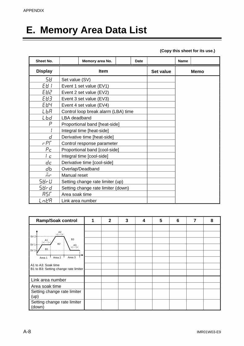
APPENDIX
A-8 IMR01W03-E9
E. Memory Area Data List
(Copy this sheet for its use.)
Sheet No. Memory area No. Date Name
Display Item Set value Memo
SV Set value (SV) EV1 Event 1 set value (EV1) EV2 Event 2 set value (EV2) EV3 Event 3 set value (EV3) EV4 Event 4 set value (EV4) LbA Control loop break alarm (LBA) time Lbd LBA deadband
P Proportional band [heat-side] 1 Integral time [heat-side] d Derivative time [heat-side]
rPT Control response parameter Pc Proportional band [cool-side] Ic Integral time [cool-side] dc Derivative time [cool-side] db Overlap/Deadband Mr Manual reset
SVrU Setting change rate limiter (up) SVrd Setting change rate limiter (down) AST Area soak time
LnKA Link area number
Ramp/Soak control 1 2 3 4 5 6 7 8
Link area number Area soak time Setting change rate limiter (up)
Setting change rate limiter (down)
A1 to A3: Soak time B1 to B3: Setting change rate limiter
B1
SV 1
Area 1 Area 2 Area 3
SV 2
SV 3
A2
A3
A1
B2
B3

APPENDIX
IMR01W03-E9 A-9
F. Parameter List
SV setting & monitor mode
Symbol Name Data range Factory
set value User
set value Page
Measured value (PV)/ Set value (SV) monitor
PV display: Input scale low to Input scale high *
SV display: SV * Remote setting (RS) input value * Manual manipulated output value
* Varies with the setting of the Decimal point position
7-5
SV Set value (SV) 1 Setting limiter low to Setting limiter high [Varies with the setting of the Decimal point position]
0 7-7
CT1 Current transformer 1 (CT1) input value monitor 2
0.0 to 30.0 A or 0.0 to 100.0 A
7-7
CT2 Current transformer 2 (CT2) input value monitor 3
0.0 to 30.0 A or 0.0 to 100.0 A
7-7
SVr Remote setting (RS) input value monitor
Setting limiter low to Setting limiter high [Varies with the setting of the Decimal point position]
7-7
EVM1 Event monitor 1 4 SV display
Event 1 (EV1) Event 2 (EV2) Event 3 (EV3) Event 4 (EV4)
7-8
EVM2 Event monitor 2 5 SV display
Heater break alarm 1 (HBA1)Heater break alarm 2 (HBA2)
7-8
MV Manipulated output value (MV1) monitor [heat-side] 6
PID control or Heat/Cool PID control: 5.0 to +105.0 %
Position proportioning PID control: When the control motor with Feedback resistance (FBR) is used: 0.0 to 100.0 %
7-9
MV2 Manipulated output value (MV2) monitor [cool-side] 7
5.0 to +105.0 % 7-10
APT Memory area soak time monitor
0 minutes 00 seconds to 199 minutes 59 seconds or 0 hours 00 minutes to 99 hours 59 minutes
7-10
ArE Memory area transfer 1 to 8
1 7-11
1 Parameters related to multi-memory area function 2 Displayed only when the CT1 input is provided. 3 Displayed only when the CT2 input is provided. 4 Displayed when the Event action is selected for any one of the Event types from 1 to 4. 5 Display when the CT1 or CT2 input is provided. This screen is not displayed when set the CT assignment to “0: None.” 6 MV1 of heat-side is not displayed when the control action is Position proportioning PID control and the input of Feedback
resistance (FBR) is not used. 7 This screen is displayed when the control action is Heat/Cool PID control.
Continued on the next page.
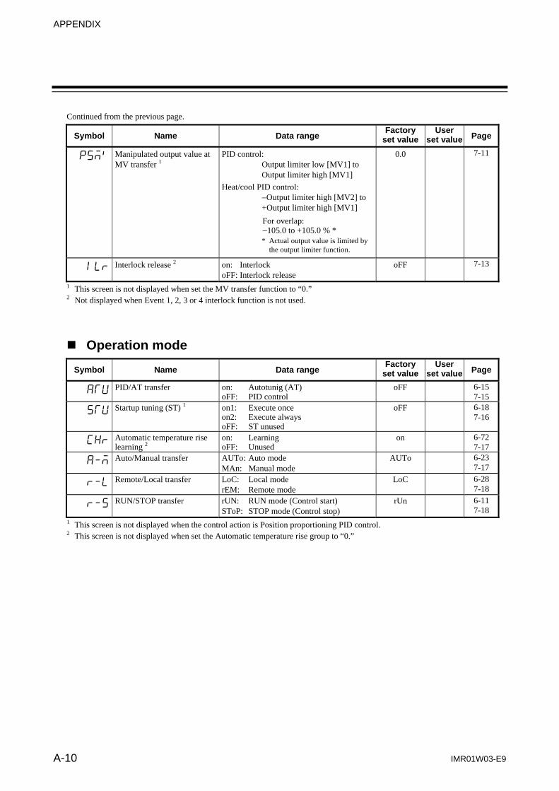
APPENDIX
A-10 IMR01W03-E9
Continued from the previous page.
Symbol Name Data range Factory
set value User
set value Page
PSM` Manipulated output value at MV transfer 1
PID control: Output limiter low [MV1] to Output limiter high [MV1] Heat/cool PID control: Output limiter high [MV2] to +Output limiter high [MV1] For overlap: 105.0 to +105.0 % *
* Actual output value is limited by the output limiter function.
0.0 7-11
ILr Interlock release 2 on: Interlock oFF: Interlock release
oFF 7-13
1 This screen is not displayed when set the MV transfer function to “0.” 2 Not displayed when Event 1, 2, 3 or 4 interlock function is not used.
Operation mode
Symbol Name Data range Factory
set value User
set value Page
ATU PID/AT transfer on: Autotunig (AT) oFF: PID control
oFF 6-15 7-15
STU Startup tuning (ST) 1 on1: Execute once on2: Execute always oFF: ST unused
oFF 6-18 7-16
CHr Automatic temperature rise learning 2
on: Learning oFF: Unused
on 6-72 7-17
A-M Auto/Manual transfer AUTo: Auto mode MAn: Manual mode
AUTo 6-23 7-17
r-L Remote/Local transfer LoC: Local mode rEM: Remote mode
LoC 6-28 7-18
r-S RUN/STOP transfer rUN: RUN mode (Control start) SToP: STOP mode (Control stop)
rUn 6-11 7-18
1 This screen is not displayed when the control action is Position proportioning PID control. 2 This screen is not displayed when set the Automatic temperature rise group to “0.”

APPENDIX
IMR01W03-E9 A-11
Parameter setting mode
Symbol Name Data range Factory
set value User
set value Page
EV1 Event 1 set value (EV1) 1, 2 Deviation: Input span to +Input span [Varies with the setting of the Decimal point position] Process and set value: Input scale low to Input scale high [Varies with the setting of the Decimal point position] Manipulated output value (MV1 or MV2): 5.0 to +105.0 %
50 7-21
EV2 Event 2 set value (EV2) 1, 2 50 7-21
EV3 Event 3 set value (EV3) 1, 2 50 7-21
EV4 Event 4 set value (EV4) 1, 2, 3 50 7-21
LbA Control loop break alarm (LBA) time 1, 4
1 to 7200 seconds oFF: Unused
480 7-22
Lbd LBA deadband 1, 4 0 to Input span [Varies with the setting of the Decimal point position]
0 7-23
P Proportional band 1 [heat-side]
TC/RTD inputs: 0 (0.0, 0.00) to Input span (Unit: C [F])[Varies with the setting of the Decimal point position]
Voltage (V)/Current (I) inputs: 0.0 to 1000.0 % of Input span
0 (0.0, 0.00): ON/OFF action
TC/RTD: 30 V/I: 30.0
7-24
I Integral time 1 [heat-side]
PID control or Heat/Cool PID control: 1 to 3600 seconds or 0.1 to 1999.9 secondsoFF: PD action [both heat-side and cool-side]
Position proportioning PID control: 1 to 3600 seconds or 0.1 to 1999.9 seconds
[Varies with the setting of the Integral/ Derivative decimal point position]
240 7-25
d Derivative time 1 [heat-side]
1 to 3600 seconds or 0.1 to 1999.9 seconds oFF: PI action [Varies with the setting of the Integral/ Derivative decimal point position]
60 7-25
rPT Control response parameter 1 0: Slow 1: Medium 2: Fast When the P or PD action is selected, this setting becomes invalid.
PID control, Position
proportioning PID control: 0
Heat/Cool PID control:
2
7-26
Pc Proportional band 1, 5 [cool-side]
TC/RTD inputs: 1 (0.1, 0.01) to Input span (Unit: C [F])[Varies with the setting of the Decimal point position]
Voltage (V)/Current (I) inputs: 0.1 to 1000.0 % of Input span
TC/RTD: 30 V/I: 30.0
7-27
1 Parameters related to Multi-memory area function 2 Not displayed when Event function is not used. 3 EV4 is not displayed when the Event 4 is used as an LBA. 4 This screen is displayed when the Event 4 is used as an LBA. 5 This screen is displayed when the control action is Heat/Cool PID control.
Continued on the next page.

APPENDIX
A-12 IMR01W03-E9
Continued from the previous page.
Symbol Name Data range Factory
set value User
set value Page
Ic Integral time 1, 2 [cool-side]
1 to 3600 seconds or 0.1 to 1999.9 seconds oFF: PD action [Varies with the setting of the Integral/ Derivative decimal point position]
240 7-27
dc Derivative time 1, 2 [cool-side]
1 to 3600 seconds or 0.1 to 1999.9 seconds oFF: PI action [Varies with the setting of the Integral/ Derivative decimal point position]
60 7-28
db Overlap/Deadband 1, 2 TC/RTD inputs: Input span to +Input span (Unit:C [F])
Voltage (V)/Current (I) inputs: 100.0 to +100.0 % of Input span
Minus () setting results in Overlap. However, the overlapping range is within the proportional range.
0 7-29
Mr Manual reset 1, 3 100.0 to +100.0 %
0.0 7-30
SVrU Setting change rate limiter (up) 1
1 (0.1, 0.01) to Input span/unit time oFF: Unused
oFF 7-31
SVrd Setting change rate limiter (down) 1
[Varies with the setting of the Decimal point position]
oFF 7-31
AST Area soak time 1 0 minutes 00 seconds to 199 minutes 59 seconds or 0 hours 00 minutes to 99 hours 59 minutes
0:00 7-32
LnKA Link area number 1 1 to 8 oFF: No link
oFF 7-33
1 Parameters related to Multi-memory area function 2 This screen is displayed when the control action is Heat/Cool PID control. 3 The screen is displayed when the Integral time [heat-side] or Integral time [cool-side] is set to “oFF.”

APPENDIX
IMR01W03-E9 A-13
Setup setting mode
Symbol Name Data range Factory
set value User
set value Page
HbA1 Heater break alarm 1 (HBA1) set value a, b
When CT is CTL-6-P-N: 0.1 to 30.0 A oFF: Not used
When CT is CTL-12-S56-10L-N: 0.1 to 100.0 A oFF: Not used
oFF 7-35
HbL1 Heater break determination point 1 a, b, c
0.1 to 100.0 % of HBA1 set value oFF: Heater break determination is invalid
30.0 7-38
HbH1 Heater melting determination point 1 a, b, c
0.1 to 100.0 % of HBA1 set value oFF: Heater melting determination is invalid
30.0 7-39
HbA2 Heater break alarm 2 (HBA2) set value d, e
When CT is CTL-6-P-N: 0.1 to 30.0 A oFF: Not used
When CT is CTL-12-S56-10L-N: 0.1 to 100.0 A oFF: Not used
oFF 7-35
HbL2 Heater break determination point 2 d, e, f
0.1 to 100.0 % of HBA2 set value oFF: Heater break determination is invalid
30.0 7-38
HbH2 Heater melting determination point 2 d, e, f
0.1 to 100.0 % of HBA2 set value oFF: Heater melting determination is invalid
30.0 7-39
Pb PV bias Input span to +Input span [Varies with the setting of the Decimal point position]
0 7-40
dF PV digital filter 0.1 to 100.0 seconds oFF: Unused
oFF 7-40
Pr PV ratio 0.500 to 1.500
1.000 7-40
PLC PV low input cut-off 0.00 to 25.00 % of input span
0.00 7-41
rb RS bias g Input span to +Input span [Varies with the setting of the Decimal point position]
0 7-42
dF2 RS digital filter g 0.1 to 100.0 seconds oFF: Unused
oFF 7-42
rr RS ratio g 0.001 to 9.999
1.000 7-42
T Proportional cycle time [heat-side]
0.1 to 100.0 seconds
20.0 h 7-43
t Proportional cycle time [cool-side]
0.1 to 100.0 seconds
20.0 h 7-43
Add1 Device address 1 i 0 to 99
0 7-44
bPS1 Communication speed 1 i 2.4: 2400 bps 4.8: 4800 bps 9.6: 9600 bps 19.2: 19200 bps 38.4: 38400 bps
19.2 7-44
a Displayed when the CT1 is provided. b This screen is not displayed when set the CT1 assignment to “0: None.” c Displayed when the HBA1 type is type B. d Displayed when the CT2 is provided. e This screen is not displayed when set the CT2 assignment to “0: None.” f Displayed when the HBA2 type is type B. g Displayed when the Remote setting (RS) is provided. h Factory set value varies depending on the instrument specification. i Displayed only when the Communication 1 is provided.
Continued on the next page.
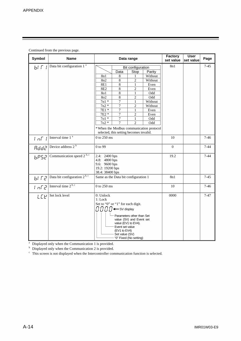
APPENDIX
A-14 IMR01W03-E9
Continued from the previous page.
Symbol Name Data range Factory
set value User
set value Page
bIT1 Data bit configuration 1 a Bit configuration
Data Stop Parity8n1 8 1 Without8n2 8 2 Without8E1 8 1 Even8E2 8 2 Even8o1 8 1 Odd8o2 8 2 Odd
7n1 * 7 1 Without 7n2 * 7 2 Without 7E1 * 7 1 Even 7E2 * 7 2 Even 7o1 * 7 1 Odd 7o2 * 7 2 Odd
* When the Modbus communication protocol selected, this setting becomes invalid.
8n1 7-45
InT1 Interval time 1 a 0 to 250 ms
10 7-46
Add2 Device address 2 b 0 to 99
0 7-44
bPS2 Communication speed 2 b, c 2.4: 2400 bps 4.8: 4800 bps 9.6: 9600 bps 19.2: 19200 bps 38.4: 38400 bps
19.2 7-44
bIT2 Data bit configuration 2 b, c Same as the Data bit configuration 1
8n1 7-45
InT2 Interval time 2 b, c 0 to 250 ms
10 7-46
LCK Set lock level 0: Unlock 1: Lock Set to “0” or “1” for each digit.
SV display
Parameters other than Set value (SV) and Event set value (EV1 to EV4). Event set value (EV1 to EV4) Set value (SV) “0” Fixed (No setting)
0000 7-47
a Displayed only when the Communication 1 is provided. b Displayed only when the Communication 2 is provided. c This screen is not displayed when the Intercontroller communication function is selected.

APPENDIX
IMR01W03-E9 A-15
Engineering mode Parameters in Engineering mode are settable only when the controller is in STOP mode. However, it is possible to check only the data even in RUN mode. There are invalid parameters when no optional function is specified.
Symbol Name Data range Factory set value
User set value Page
F10. Function block 10 This is first parameter symbol of Function block 10.
SPCH STOP display 0: “SToP” is displayed on the PV display. 1: “SToP” is displayed on the SV display.
1 7-62
dE Bar graph display 0: No display 4: Deviation value 1: MV 5: CT1 input value 2: PV 6: CT2 input value 3: SV monitor
1 7-63
dEUT Bar graph display resolution 1 to 100 digit/dot
100 7-65
dSoP PV flashing display at input error
0: Flashing display 1: Non-flashing display
0 7-66
F11. Function block 11 This is first parameter symbol of Function block 11.
Fn1 Direct key 1 0: Unused 1: A/M transfer key (Type 1, Type 2)
1 7-67
Fn2 Direct key 2 0: Unused 1: MONI key (For Type 1) or
R/L transfer key (For Type 2)
1 7-67
Fn3 Direct key 3 0: Unused 1: AREA key (For Type 1) or
RUN/STOP transfer key (For Type 2)
1 7-68
Fn Direct key type 1: Type 1 2: Type 2
1 7-68
F21. Function block 21 This is first parameter symbol of Function block 21.
InP Input type 0: TC input K 1: TC input J 2: TC input R 3: TC input S 4: TC input B 5: TC input E 6: TC input N 7: TC input T 8: TC input W5Re/W26Re 9: TC input PLII 10: TC input U 11: TC input L 12: RTD input Pt100 13: RTD input JPt100 14: Current input 0 to 20 mA DC 15: Current input 4 to 20 mA DC 16: Voltage (high) input 0 to 10 V DC 17: Voltage (high) input 0 to 5 V DC 18: Voltage (high) input 1 to 5 V DC 19: Voltage (low) input 0 to 1 V DC 20: Voltage (low) input 0 to 100 mV DC 21: Voltage (low) input 0 to 10 mV DC 24: Voltage (high) input ±1 V DC 25: Voltage (low) input ±100 mV DC 26: Voltage (low) input ±10 mV DC
0 a 7-69
a Factory set value varies depending on the instrument specification. Continued on the next page.

APPENDIX
IMR01W03-E9 A-16
Continued from the previous page.
Symbol Name Data range Factory
set value User
set valuePage
UnIT Display unit 0: °C 1: °F Use to select the temperature unit for Thermocouple (TC) and RTD inputs.
0 a 7-71
PGdP Decimal point position 0: No decimal place 1: One decimal place 2: Two decimal places 3: Three decimal places 4: Four decimal places TC input: K, J, E: Only 0 or 1 can be set. T, U, L: Only 1 can be set. Other than the above: Only 0 can be set. RTD input: From 0 to 2 can be set. V/I inputs: From 0 to 4 can be set.
0 a 7-71
PGSH Input scale high TC/RTD inputs: Input scale low to Maximum value of the selected input range
Voltage (V)/Current (I) inputs: 19999 to +19999
[Varies with the setting of the Decimal point position]
Maximum value of the selected input range a
7-72
PGSL Input scale low TC/RTD inputs: Minimum value of the selected input range to Input scale high
Voltage (V)/Current (I) inputs: 19999 to +19999
[Varies with the setting of the Decimal point position]
Minimum value of the selected input range a
7-72
PoV Input error determination point (high)
Input scale low (5 % of input span) to Input scale high + (5 % of input span)
Input scale high + (5 % of input span) a
7-74
Pun Input error determination point (low)
[Varies with the setting of the Decimal point position]
Input scale low (5 % of input span) a
7-74
boS Burnout direction 0: Upscale 1: Downscale Valid only when the TC input and Voltage (low) input are selected.
0 7-75
Sqr Square root extraction 0: Unused 1: Used 0 7-75
PFrq Power supply frequency 0: 50 Hz 1: 60 Hz 0 7-76
SMP Sampling cycle 0: 50 ms 1: 100 ms 2: 250 ms 1 7-76
F22. Function block 22 This is first parameter symbol of Function block 22.
rInP Remote setting input type 14: 0 to 20 mA DC 18: 1 to 5 V DC 15: 4 to 20 mA DC 19: 0 to 1 V DC 16: 0 to 10 V DC 20: 0 to 100 mV DC17: 0 to 5 V DC 21: 0 to 10 mV DC
15 a 7-77
F23. Function block 23 This is first parameter symbol of Function block 23.
dISL Digital input (DI) assignment 1 to 8 [Refer to Table 1 (P. A-24).] 1 7-78 a Factory set value varies depending on the instrument specification.
Continued on the next page.

APPENDIX
IMR01W03-E9 A-17
Continued from the previous page.
Symbol Name Data range Factory
set value User
set valuePage
F30. Function block 30 This is first parameter symbol of Function block 30.
LoGC Output assignment 1 to 7 [Refer to Table 2 (P. A-24).] 2 7-79
oTT1 Timer 1 0.0 to 600.0 seconds 0.0 7-80
oTT2 Timer 2 0.0 7-80
oTT3 Timer 3 0.0 7-80
oTT4 Timer 4 0.0 7-80
EXC Energized/De-energized SV display
DO1: 0: Energized 1: De-energized
DO2: 0: Energized 1: De-energized
DO3: 0: Energized 1: De-energized
DO4: 0: Energized 1: De-energized
0000 7-80
ALC1 Alarm (ALM) lamp lighting condition 1 a
0: ALM lamp is not lit 1: ALM lamp is lit SV display
EV1 EV2 EV3 EV4
1111 7-81
ALC2 Alarm (ALM) lamp lighting condition 2 a
0: ALM lamp is not lit 1: ALM lamp is lit
SV display
HBA1 HBA2
0011 7-81
SS Output status at STOP mode 0: OFF 1: Action continued
SV display
Event function Transmission output “0” fixed (No setting) “0” fixed (No setting)
0000 7-82
F33. Function block 33 This is first parameter symbol of Function block 33.
Ao Transmission output type 0: None 1: PV 2: Set value (SV) monitor 3: Deviation value 4: MV1 [heat-side] 5: MV2 [cool-side] 6: Set value (SV) 7: Remote setting (RS) input value
1 7-83
AHS Transmission output scale high
When the PV, SV, SV monitor and RS: Input scale low to Input scale high [Varies with the setting of the Decimal point position]
When the MV1 and MV2: 5.0 to +105.0 %
When the deviation value: Input span to +Input span
Input scale high
7-84
ALS Transmission output scale low
Input scale low
7-84
a The ALM lamp is lit through the OR operation of EV1, EV2, EV3, EV4, HBA1 and HBA2 each of which is set to “1: ALM lamp is lit.”
Continued on the next page.

APPENDIX
IMR01W03-E9 A-18
Continued from the previous page.
Symbol Name Data range Factory
set value User
set valuePage
F41. Function block 41 This is first parameter symbol of Function block 41.
ES1 Event 1 type 0: None 1: Deviation high 1 2: Deviation low 1 3: Deviation high/low 1 4: Band 1 5: Process high 1 6: Process low 1 7: SV high 8: SV low 9: Unused 10: MV1 high [heat-side] 1, 2 11: MV1 low [heat-side] 1, 2 12: MV2 high [cool-side] 1 13: MV2 low [cool-side] 1 1 Event hold action is available. 2 Feedback resistance (FBR) input value is
displayed when the control motor with Feedback resistance (FBR) is used.
0 a
7-85
EHo1 Event 1 hold action 0: OFF 2: Re-hold action ON1: Hold action ON
0 a 7-87
EIL1 Event 1 interlock 0: Unused 1: Used
0 7-89
EH1 Event 1 differential gap Deviation, process or set value: 0 to Input span [Varies with the setting of the Decimal point position]
MV: 0.0 to 110.0 %
2 a 7-90
EVT1 Event 1 delay timer 0.0 to 600.0 seconds 0.0 7-91
EEo1 Force ON of Event 1 action 0: Invalid 1: Valid
SV display
Event output turned on at input error occurrence
Event output turned on in Manual mode
Event output turned on during the Autotuning function (AT) is being executed
Event output turned on during the Setting change rate limiter is being operated
0000 7-93
F42. Function block 42 This is first parameter symbol of Function block 42.
ES2 Event 2 type Same as Event 1 type 7-95
EHo2 Event 2 hold action Same as Event 1 hold action 7-97
EIL2 Event 2 interlock Same as Event 1 interlock 7-98
EH2 Event 2 differential gap Same as Event 1 differential gap 7-99
EVT2 Event 2 delay timer Same as Event 1 delay timer 7-100
EEo2 Force ON of Event 2 action Same as Force ON of Event 1 action 7-101
F43. Function block 43 This is first parameter symbol of Function block 43.
ES3 Event 3 type Same as Event 1 type 7-102
EHo3 Event 3 hold action Same as Event 1 hold action 7-104a Factory set value varies depending on the instrument specification.
Continued on the next page.

APPENDIX
IMR01W03-E9 A-19
Continued from the previous page.
Symbol Name Data range Factory
set value User
set value Page
EIL3 Event 3 interlock Same as Event 1 interlock 7-105
EH3 Event 3 differential gap Same as Event 1 differential gap 7-106
EVT3 Event 3 delay timer Same as Event 1 delay timer 7-107
EEo3 Force ON of Event 3 action Same as Force ON of Event 1 action 7-108
F44. Function block 44 This is first parameter symbol of Function block 44.
ES4 Event 4 type 9: Control loop break alarm (LBA) The other data is the same as an Event 1 type.
7-109
EHo4 Event 4 hold action a Same as Event 1 hold action 7-111
EIL4 Event 4 interlock Same as Event 1 interlock 7-112
EH4 Event 4 differential gap a Same as Event 1 differential gap The invalidity in case of the LBA.
7-113
EVT4 Event 4 delay timer Same as Event 1 delay timer 7-114
EEo4 Force ON of Event 4 action a Same as Force ON of Event 1 action 7-115
F45. Function block 45 This is first parameter symbol of Function block 45.
CTr1 CT1 ratio 0 to 9999 CT type: CTL-6-P-N CTL-12-S56-10L-N
800 b
7-116
CTA1 CT1 assignment 0: None 2: OUT2 1: OUT1 3 to 6: Do not set this one
1 7-117
HbS1 Heater break alarm 1 (HBA1) type
0: Heater break alarm 1 (HBA1) type A 1: Heater break alarm 1 (HBA1) type B
0 b 7-117
HbC1 Number of heater break alarm 1 (HBA1) delay times
0 to 255 5 7-119
F46. Function block 46. This is first parameter symbol of Function block 46.
CTr2 CT2 ratio 0 to 9999 CT type: CTL-6-P-N CTL-12-S56-10L-N
800 b
7-120
CTA2 CT2 assignment 0: None 2: OUT2 1: OUT1 3 to 6: Do not set this one
0 7-121
HbS2 Heater break alarm 2 (HBA2) type
0: Heater break alarm 2 (HBA2) type A 1: Heater break alarm 2 (HBA2) type B
0 7-122
HbC2 Number of heater break alarm 2 (HBA2) delay times
0 to 255 5 7-122
F50. Function block 50 This is first parameter symbol of Function block 50.
Pb Hot/Cold start 0: Hot start 1 1: Hot start 2 2: Cold start 3: Stop start
0 7-123
PbA Start determination point 0 to Input span (The unit is the same as input value.) (0: Action depending on the Hot/Cold start selection) [Varies with the setting of the Decimal point position]
3 % of input span
7-124
CAM External input type 0: Remote setting (RS) input1: Intercontroller communication cascade
control 2: Intercontroller communication ratio
setting
0 7-125
a When the Control loop break alarm (LBA) is selected, the setting becomes invalid. b Factory set value varies depending on the instrument specification.
Continued on the next page.
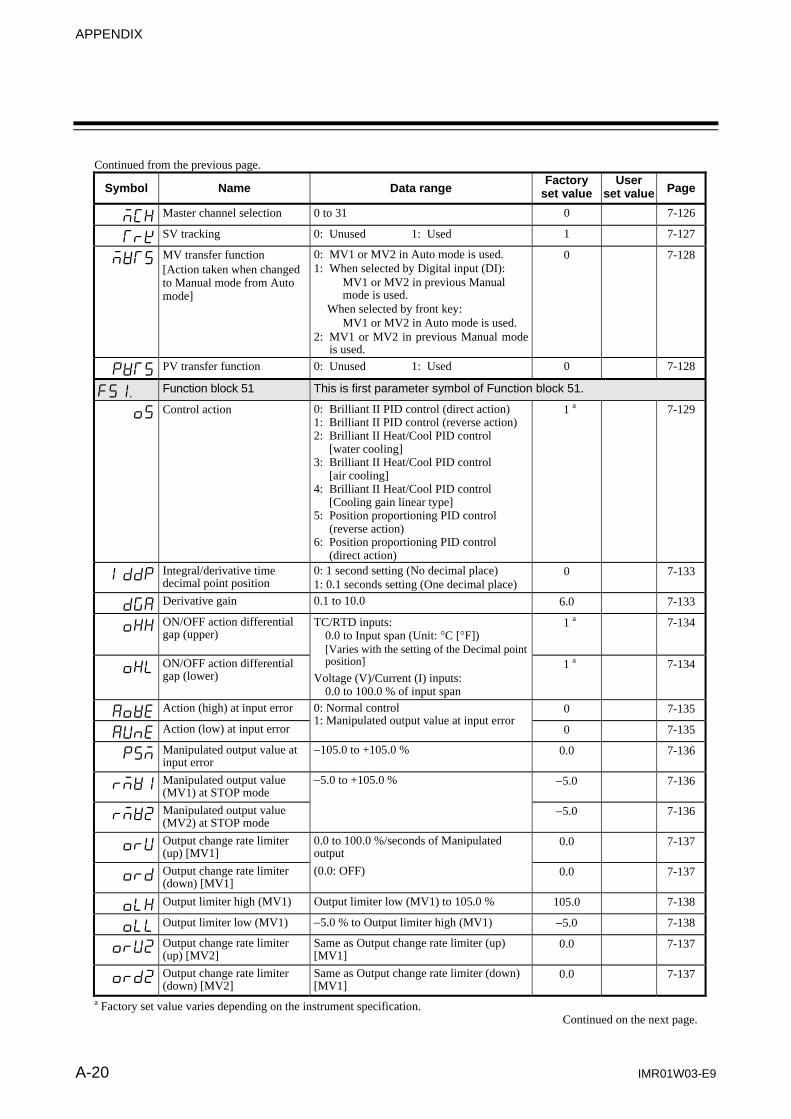
APPENDIX
A-20 IMR01W03-E9
Continued from the previous page. Symbol Name Data range
Factory set value
User set value Page
MCH Master channel selection 0 to 31 0 7-126
TrK SV tracking 0: Unused 1: Used 1 7-127
MVTS MV transfer function [Action taken when changed to Manual mode from Auto mode]
0: MV1 or MV2 in Auto mode is used. 1: When selected by Digital input (DI):
MV1 or MV2 in previous Manual mode is used.
When selected by front key: MV1 or MV2 in Auto mode is used.
2: MV1 or MV2 in previous Manual mode is used.
0 7-128
PVTS PV transfer function 0: Unused 1: Used 0 7-128
F51. Function block 51 This is first parameter symbol of Function block 51.
oS Control action 0: Brilliant II PID control (direct action) 1: Brilliant II PID control (reverse action) 2: Brilliant II Heat/Cool PID control
[water cooling] 3: Brilliant II Heat/Cool PID control
[air cooling] 4: Brilliant II Heat/Cool PID control
[Cooling gain linear type] 5: Position proportioning PID control
(reverse action) 6: Position proportioning PID control
(direct action)
1 a 7-129
IddP Integral/derivative time decimal point position
0: 1 second setting (No decimal place) 1: 0.1 seconds setting (One decimal place)
0 7-133
dGA Derivative gain 0.1 to 10.0 6.0 7-133
oHH ON/OFF action differential gap (upper)
TC/RTD inputs: 0.0 to Input span (Unit: C [F]) [Varies with the setting of the Decimal point position]
Voltage (V)/Current (I) inputs: 0.0 to 100.0 % of input span
1 a 7-134
oHL ON/OFF action differential gap (lower)
1 a 7-134
AoVE Action (high) at input error 0: Normal control 1: Manipulated output value at input error
0 7-135
AUnE Action (low) at input error 0 7-135
PSM Manipulated output value at input error
105.0 to +105.0 % 0.0 7-136
rMV1 Manipulated output value (MV1) at STOP mode
5.0 to +105.0 % 5.0 7-136
rMV2 Manipulated output value (MV2) at STOP mode
5.0 7-136
orU Output change rate limiter (up) [MV1]
0.0 to 100.0 %/seconds of Manipulated output
0.0 7-137
ord Output change rate limiter (down) [MV1]
(0.0: OFF) 0.0 7-137
oLH Output limiter high (MV1) Output limiter low (MV1) to 105.0 % 105.0 7-138
oLL Output limiter low (MV1) 5.0 % to Output limiter high (MV1) 5.0 7-138
orU2 Output change rate limiter (up) [MV2]
Same as Output change rate limiter (up) [MV1]
0.0 7-137
ord2 Output change rate limiter (down) [MV2]
Same as Output change rate limiter (down) [MV1]
0.0 7-137
a Factory set value varies depending on the instrument specification. Continued on the next page.
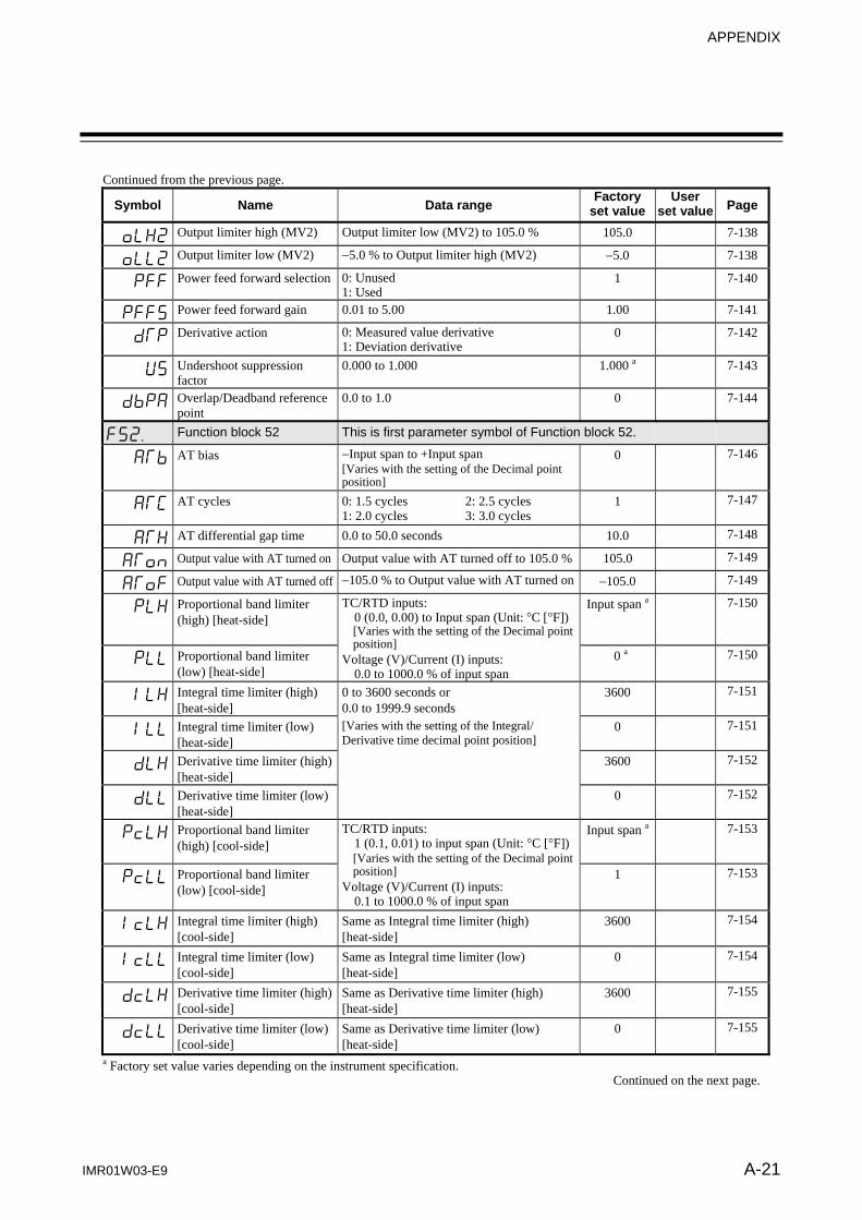
APPENDIX
IMR01W03-E9 A-21
Continued from the previous page. Symbol Name Data range
Factory set value
User set value Page
oLH2 Output limiter high (MV2) Output limiter low (MV2) to 105.0 % 105.0 7-138
oLL2 Output limiter low (MV2) 5.0 % to Output limiter high (MV2) 5.0 7-138
PFF Power feed forward selection 0: Unused 1: Used
1 7-140
PFFS Power feed forward gain 0.01 to 5.00 1.00 7-141
dTP Derivative action 0: Measured value derivative 1: Deviation derivative
0 7-142
US Undershoot suppression factor
0.000 to 1.000 1.000 a 7-143
dbPA Overlap/Deadband reference point
0.0 to 1.0 0 7-144
F52. Function block 52 This is first parameter symbol of Function block 52.
ATb AT bias Input span to +Input span [Varies with the setting of the Decimal point position]
0 7-146
ATC AT cycles 0: 1.5 cycles 2: 2.5 cycles 1: 2.0 cycles 3: 3.0 cycles
1 7-147
ATH AT differential gap time 0.0 to 50.0 seconds 10.0 7-148
AToN Output value with AT turned on Output value with AT turned off to 105.0 % 105.0 7-149
AToF Output value with AT turned off 105.0 % to Output value with AT turned on 105.0 7-149
PLH Proportional band limiter (high) [heat-side]
TC/RTD inputs: 0 (0.0, 0.00) to Input span (Unit: C [F])[Varies with the setting of the Decimal point position]
Voltage (V)/Current (I) inputs: 0.0 to 1000.0 % of input span
Input span a 7-150
PLL Proportional band limiter (low) [heat-side]
0 a 7-150
ILH Integral time limiter (high) [heat-side]
0 to 3600 seconds or 0.0 to 1999.9 seconds
3600 7-151
ILL Integral time limiter (low) [heat-side]
[Varies with the setting of the Integral/ Derivative time decimal point position]
0 7-151
dLH Derivative time limiter (high) [heat-side]
3600 7-152
dLL Derivative time limiter (low) [heat-side]
0 7-152
PcLH Proportional band limiter (high) [cool-side]
TC/RTD inputs: 1 (0.1, 0.01) to input span (Unit: C [F])[Varies with the setting of the Decimal point position]
Voltage (V)/Current (I) inputs: 0.1 to 1000.0 % of input span
Input span a 7-153
PcLL Proportional band limiter (low) [cool-side]
1 7-153
IcLH Integral time limiter (high) [cool-side]
Same as Integral time limiter (high) [heat-side]
3600 7-154
IcLL Integral time limiter (low) [cool-side]
Same as Integral time limiter (low) [heat-side]
0 7-154
dcLH Derivative time limiter (high) [cool-side]
Same as Derivative time limiter (high) [heat-side]
3600 7-155
dcLL Derivative time limiter (low) [cool-side]
Same as Derivative time limiter (low) [heat-side]
0 7-155
a Factory set value varies depending on the instrument specification. Continued on the next page.

APPENDIX
A-22 IMR01W03-E9
Continued from the previous page. Symbol Name Data range
Factory set value
User set value Page
PAJ Proportional band adjusting factor [heat-side]
0.01 to 10.00 times 1.00 7-156
IAJ Integral time adjusting factor [heat-side]
1.00 7-156
dAJ Derivative time adjusting factor [heat-side]
1.00 7-157
PcAJ Proportional band adjusting factor [cool-side]
1.00 7-156
IcAJ Integral time adjusting factor [cool-side]
1.00 7-156
dcAJ Derivative time adjusting factor [cool-side]
1.00 7-157
F53. Function block 53 This is first parameter symbol of Function block 53.
Ydb Open/Close output neutral zone
0.1 to 10.0 % of output 2.0 7-158
YHS Open/Close output differential gap
0.1 to 5.0 % of output 1.0 7-159
Ybr Action at feedback resistance (FBR) input error
0: Action depending on the valve action at STOP
1: Control action continued
0 7-159
PoS Feedback adjustment At the Adjustment preparation screen, press the shift key for 5 seconds to start the adjustment.
7-160
MoT Control motor time 5 to 1000 seconds 10 7-161
oLA Integrated output limiter 0.0 to 200.0 % of control motor time 0.0: Integrated output limiter function OFFThis value becomes invalid when Feedback resistance (FBR) input is used.
150.0 7-161
VAL Valve action at STOP 0: Close-side output OFF, Open-side output OFF
1: Close-side output ON, Open-side output OFF
2: Close-side output OFF, Open-side output ON
0 7-162
YASo Action at saturated output 0: Invalid 1: Valid
0 7-162
F54. Function block 54 This is first parameter symbol of Function block 54.
STS ST start condition 0: Activate the Startup tuning (ST) function when the power is turned on; when transferred from STOP to RUN; or when the Set value (SV) is changed.
1: Activate the Startup tuning (ST) function when the power is turned on; or when transferred from STOP to RUN.
2: Activate the Startup tuning (ST) function when the Set value (SV) is changed.
0 7-163
STPK ST proportional band adjusting factor
0.01 to 10.00 times 1.00 7-163
STIK ST integral time adjusting factor
1.00 7-164
STdK ST derivative time adjusting factor
1.00 7-164
a Factory set value varies depending on the instrument specification. Continued on the next page.

APPENDIX
IMR01W03-E9 A-23
Continued from the previous page.
Symbol Name Data range Factory
set value User
set value Page
F55. Function block 55 This is first parameter symbol of Function block 55.
CHrG Automatic temperature rise group
0 to 16 (0: Automatic temperature rise function OFF)
0 7-165
rSG RUN/STOP group 0 to 16 (0: RUN/STOP group function OFF)
0 7-166
CHrd Automatic temperature rise dead time
0.1 to 1999.9 seconds 10.0 7-167
CHrT Automatic temperature rise gradient data
0.1 to Input span/minutes 1.0 7-167
F60. Function block 60 This is first parameter symbol of Function block 60.
CMP1 Communication 1 protocol 0: RKC communication 1: Modbus
0 a 7-168
CMP2 Communication 2 protocol 0: RKC communication 1: Modbus 2: Intercontroller communication
2 7-168
F70. Function block 70 This is first parameter symbol of Function block 70.
SVrT Setting change rate limiter unit time
1 to 3600 seconds 60 7-169
STdP Soak time unit 0: 0 hours 00 minutes to 99 hours 59 minutes
1: 0 minutes 00 seconds to 199 minutes 59 seconds
1 7-169
F71. Function block 71 This is first parameter symbol of Function block 71.
SLH Setting limiter high Setting limiter low to Input scale high [Varies with the setting of the Decimal point position]
Input scale high
7-170
SLL Setting limiter low Input scale low to Setting limiter high [Varies with the setting of the Decimal point position]
Input scale low
7-170
F91. Function block 91 This is first parameter symbol of Function block 91.
C277 ROM version monitor Display the version of loaded software. 7-171
WT Integrated operating time monitor
0 to 19999 hours 7-171
TCJ Holding peak value ambient temperature monitor
10.0 to +100.0 C 7-172
HEAT Power feed forward input value monitor
0.0 to 160.0 % Display in the percentage of the load voltage (rated value).
7-172
a Factory set value varies depending on the instrument specification.
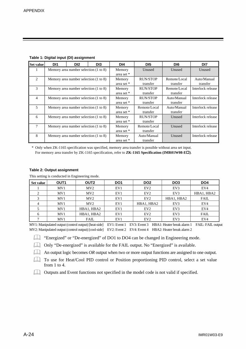
APPENDIX
A-24 IMR01W03-E9
Table 1: Digital input (DI) assignment
Set value DI1 DI2 DI3 DI4 DI5 DI6 DI7 1 Memory area number selection (1 to 8) Memory
area set * Unused
Unused Unused
2 Memory area number selection (1 to 8) Memory area set *
RUN/STOP transfer
Remote/Local transfer
Auto/Manual transfer
3 Memory area number selection (1 to 8) Memory area set *
RUN/STOP transfer
Remote/Local transfer
Interlock release
4 Memory area number selection (1 to 8) Memory area set *
RUN/STOP transfer
Auto/Manual transfer
Interlock release
5 Memory area number selection (1 to 8) Memory area set *
Remote/Local transfer
Auto/Manual transfer
Interlock release
6 Memory area number selection (1 to 8) Memory area set *
RUN/STOP transfer
Unused Interlock release
7 Memory area number selection (1 to 8) Memory area set *
Remote/Local transfer
Unused Interlock release
8 Memory area number selection (1 to 8) Memory area set *
Auto/Manual transfer
Unused Interlock release
* Only when ZK-1165 specification was specified, memory area transfer is possible without area set input. For memory area transfer by ZK-1165 specification, refer to ZK-1165 Specification (IMR01W08-E).
Table 2: Output assignment
This setting is conducted in Engineering mode.
Set value OUT1 OUT2 DO1 DO2 DO3 DO4
1 MV1 MV2 EV1 EV2 EV3 EV4 2 MV1 MV2 EV1 EV2 EV3 HBA1, HBA23 MV1 MV2 EV1 EV2 HBA1, HBA2 FAIL 4 MV1 MV2 EV1 HBA1, HBA2 EV3 EV4 5 MV1 HBA1, HBA2 EV1 EV2 EV3 EV4 6 MV1 HBA1, HBA2 EV1 EV2 EV3 FAIL 7 MV1 FAIL EV1 EV2 EV3 EV4
MV1: Manipulated output (control output) [heat-side] EV1: Event 1 EV3: Event 3 HBA1: Heater break alarm 1 FAIL: FAIL output MV2: Manipulated output (control output) [cool-side] EV2: Event 2 EV4: Event 4 HBA2: Heater break alarm 2
“Energized” or “De-energized” of DO1 to DO4 can be changed in Engineering mode.
Only “De-energized” is available for the FAIL output. No “Energized” is available.
An output logic becomes OR output when two or more output functions are assigned to one output.
To use for Heat/Cool PID control or Position proportioning PID control, select a set value from 1 to 4.
Outputs and Event functions not specified in the model code is not valid if specified.

APPENDIX
IMR01W03-E9 A-25
G. Seal [for Unit and Direct key type 2] (accessory attached)
Model code
SAP-306
For FB400 direct key (Type 2) For FB900 direct key (Type 2) Usage example of the unit seal
Please use only the unit seal meeting the controlled object.
For unit
C Unit seal

IMR01W03-E9 A-26
MEMO
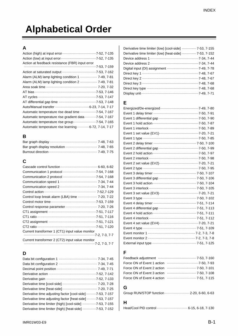
INDEX
IMR01W03-E9 B-1
Alphabetical Order
A Action (high) at input error ······························ 7-52, 7-135
Action (low) at input error ······························· 7-52, 7-135Action at feedback resistance (FBR) input error ································································ 7-53, 7-159
Action at saturated output ······························ 7-53, 7-162
Alarm (ALM) lamp lighting condition 1 ··············· 7-49, 7-81
Alarm (ALM) lamp lighting condition 2 ··············· 7-49, 7-81
Area soak time ············································· 7-20, 7-32
AT bias ······················································ 7-53, 7-146
AT cycles ··················································· 7-53, 7-147
AT differential gap time ································· 7-53, 7-148
Auto/Manual transfer ······························ 6-23, 7-14, 7-17
Automatic temperature rise dead time ·············· 7-54, 7-167
Automatic temperature rise gradient data ·········· 7-54, 7-167
Automatic temperature rise group ···················· 7-54, 7-165
Automatic temperature rise learning ··········· 6-72, 7-14, 7-17
B Bar graph display ·········································· 7-48, 7-63
Bar graph display resolution ···························· 7-48, 7-65
Burnout direction ··········································· 7-49, 7-75
C Cascade control function ································ 6-60, 6-82
Communication 1 protocol ····························· 7-54, 7-168
Communication 2 protocol ····························· 7-54, 7-168
Communication speed 1 ································· 7-34, 7-44
Communication speed 2 ································· 7-34, 7-44
Control action ·············································· 7-52,7-129
Control loop break alarm (LBA) time ················· 7-20, 7-22
Control motor time ········································ 7-53, 7-159
Control response parameter ···························· 7-20, 7-26
CT1 assignment ·········································· 7-51, 7-117
CT1 ratio ···················································· 7-51, 7-116
CT2 assignment ·········································· 7-51, 7-121
CT2 ratio ···················································· 7-51, 7-120Current transformer 1 (CT1) input value monitor ······························································· 7-2, 7-3, 7-7
Current transformer 2 (CT2) input value monitor ······························································· 7-2, 7-3, 7-7
D Data bit configuration 1 ·································· 7-34, 7-45
Data bit configuration 2 ·································· 7-34, 7-45
Decimal point position ···································· 7-49, 7-71
Derivative action ·········································· 7-52, 7-142
Derivative gain ············································ 7-52, 7-133
Derivative time [cool-side] ······························· 7-20, 7-28
Derivative time [heat-side] ······························· 7-20, 7-25
Derivative time adjusting factor [cool-side] ········· 7-53, 7-157
Derivative time adjusting factor [heat-side] ········ 7-53, 7-157
Derivative time limiter (high) [cool-side] ············ 7-53, 7-155
Derivative time limiter (high) [heat-side] ············ 7-53, 7-152
Derivative time limiter (low) [cool-side] ············· 7-53, 7-155
Derivative time limiter (low) [heat-side] ············· 7-53, 7-152
Device address 1 ···········································7-34, 7-44
Device address 2 ···········································7-34, 7-44
Digital input (DI) assignment ····························7-49, 7-78
Direct key 1 ··················································7-48, 7-67
Direct key 2 ··················································7-48, 7-67
Direct key 3 ··················································7-48, 7-68
Direct key type ··············································7-48, 7-68
Display unit ···················································7-49, 7-71
EEnergized/De-energized ··································7-49, 7-80
Event 1 delay timer ········································7-50, 7-91
Event 1 differential gap ···································7-50, 7-90
Event 1 hold action ·········································7-50, 7-87
Event 1 interlock ············································7-50, 7-89
Event 1 set value (EV1) ···································7-20, 7-21
Event 1 type ·················································7-50, 7-85
Event 2 delay timer ······································ 7-50, 7-100
Event 2 differential gap ···································7-50, 7-99
Event 2 hold action ·········································7-50, 7-97
Event 2 interlock ············································7-50, 7-98
Event 2 set value (EV2) ···································7-20, 7-21
Event 2 type ·················································7-50, 7-95
Event 3 delay timer ······································ 7-50, 7-107
Event 3 differential gap ································· 7-50, 7-106
Event 3 hold action ······································· 7-50, 7-104
Event 3 interlock ·········································· 7-50, 7-105
Event 3 set value (EV3) ···································7-20, 7-21
Event 3 type ··············································· 7-50, 7-102
Event 4 delay timer ······································ 7-51, 7-114
Event 4 differential gap ································· 7-51, 7-113
Event 4 hold action ······································· 7-51, 7-111
Event 4 interlock ·········································· 7-51, 7-112
Event 4 set value (EV4) ···································7-20, 7-21
Event 4 type ··············································· 7-51, 7-109
Event monitor 1 ·········································· 7-2, 7-3, 7-8
Event monitor 2 ·········································· 7-2, 7-3, 7-8
External input type ······································· 7-51, 7-125
FFeedback adjustment ·································· 7-53, 7-160
Force ON of Event 1 action ····························7-50, 7-93
Force ON of Event 2 action ·························· 7-50, 7-101
Force ON of Event 3 action ·························· 7-50, 7-108
Force ON of Event 4 action ·························· 7-51, 7-115
GGroup RUN/STOP function ······················ 2-20, 6-60, 6-63
HHeat/Cool PID control ··························· 6-15, 6-18, 7-130

INDEX
B-2 IMR01W03-E9
Heater break alarm 1 (HBA1) set value ············· 7-34, 7-35
Heater break alarm 1 (HBA1) type ··················· 7-51, 7-118
Heater break alarm 2 (HBA2) set value ············· 7-34, 7-35
Heater break alarm 2 (HBA2) type ··················· 7-51, 7-122
Heater break determination point 1 ··················· 7-34, 7-38
Heater break determination point 2 ··················· 7-34, 7-38
Heater melting determination point 1 ················· 7-34, 7-39
Heater melting determination point 2 ················· 7-34, 7-39
Hold action ·························································· 7-87Holding peak value ambient temperature monitor ································································ 7-54, 7-172
Hot/Cold start ·············································· 7-51, 7-123
I Input error determination point (high) ················ 7-49, 7-74
Input error determination point (low) ·················· 7-49, 7-74
Input scale high ············································ 7-49, 7-72
Input scale low ············································· 7-49, 7-72
Input type ···················································· 7-49, 7-69
Integral time [cool-side] ·································· 7-20, 7-27
Integral time [heat-side] ·································· 7-20, 7-25
Integral time adjusting factor [cool-side] ············ 7-53, 7-156
Integral time adjusting factor [heat-side] ············ 7-53, 7-156
Integral time limiter (high) [cool-side] ················ 7-53, 7-154
Integral time limiter (high) [heat-side] ··············· 7-53, 7-151
Integral time limiter (low) [cool-side] ················· 7-53, 7-154
Integral time limiter (low) [heat-side] ················· 7-53, 7-151
Integral/derivative time decimal point position ···· 7-52, 7-133
Integrated operating time monitor ···················· 7-54, 7-171
Integrated output limiter ································· 7-53, 7-161
Interlock release ······································· 7-2, 7-3, 7-13
Interval time 1 ·············································· 7-34, 7-46
Interval time 2 ·············································· 7-34, 7-46
L LBA deadband ············································· 7-20, 7-23
Link area number ·········································· 7-20, 7-33
Loader communication connector ····························· 1-10
Loader communication ··········································· 1-14
M
Manipulated output value (MV1) at STOP mode · 7-52, 7-136Manipulated output value (MV1) monitor [heat-side] ······························································· 7-2, 7-3, 7-9
Manipulated output value (MV2) at STOP mode · 7-52, 7-136
Manipulated output value (MV2) monitor [cool-side]
····························································· 7-2, 7-3, 7-10
Manipulated output value at input error ············· 7-52, 7-136
Manipulated output value at MV transfer ········ 7-2, 7-3, 7-11
Manual reset ················································ 7-20, 7-30
Master channel selection ······························· 7-51, 7-126
Measured value (PV)/Set value (SV) monitor ···· 7-2, 7-3, 7-5
Memory area soak time monitor ··················· 7-2, 7-3, 7-10
Memory area transfer ································ 7-2, 7-3, 7-11
MV transfer function ····································· 7-51, 7-128
N
Number of heater break alarm 1 (HBA1) delay times
································································ 7-51, 7-119Number of heater break alarm 2 (HBA2) delay times ································································ 7-51, 7-122
OON/OFF action differential gap (lower) ············· 7-52, 7-134
ON/OFF action differential gap (upper) ············· 7-52, 7-134
Open/Close output differential gap ·················· 7-53, 7-159
Open/Close output neutral zone ······················ 7-53, 7-158
Output assignment ·········································7-49, 7-79
Output change rate limiter (down) [MV1] ··········· 7-52, 7-137
Output change rate limiter (down) [MV2] ··········· 7-52, 7-137
Output change rate limiter (up) [MV1] ··············· 7-52, 7-137
Output change rate limiter (up) [MV2] ··············· 7-52, 7-137
Output limiter high (MV1) ······························· 7-52, 7-138
Output limiter high (MV2) ······························· 7-52, 7-138
Output limiter low (MV1) ································ 7-52, 7-138
Output limiter low (MV2) ································ 7-52, 7-138
Output status at STOP mode ···························7-49, 7-82
Output value with AT turned off ······················· 7-53, 7-149
Output value with AT turned on ······················· 7-53, 7-149
Overlap/Deadband ·········································7-20, 7-29
Overlap/Deadband reference point ·················· 7-52, 7-144
P
PID/AT transfer ····································· 6-15, 7-14, 7-15
PID control ··········································· 6-15, 6-19, 6-73
Position proportioning control ··················· 4-7, 6-40, 7-130
Power feed forward gain ································ 7-52, 7-141
Power feed forward input value monitor ············ 7-54, 7-172
Power feed forward selection ························· 7-52, 7-140
Power supply frequency ··································7-49, 7-76
Proportional band [cool-side] ····························7-20, 7-27
Proportional band [heat-side] ···························7-20, 7-24
Proportional band adjusting factor [cool-side] ····· 7-53, 7-156
Proportional band adjusting factor [heat-side] ···· 7-53, 7-156
Proportional band limiter (high) [cool-side] ········ 7-53, 7-153
Proportional band limiter (high) [heat-side] ········ 7-53, 7-150
Proportional band limiter (low) [cool-side] ·········· 7-53, 7-153
Proportional band limiter (low) [heat-side] ········· 7-53, 7-150
Proportional cycle time [cool-side] ·····················7-34, 7-43
Proportional cycle time [heat-side] ·····················7-34, 7-43
PV bias ························································7-34, 7-40
PV digital filter ···············································7-34, 7-40
PV flashing display at input error ·······················7-48, 7-66
PV low input cut-off ········································7-34, 7-41
PV ratio ·······················································7-34, 7-40
PV transfer function ······································ 7-51, 7-128

INDEX
IMR01W03-E9 B-3
R Ratio setting function ······························· 2-2, 6-60, 6-91
Re-hold action ······················································ 7-88
Remote setting (RS) input value monitor ·········· 7-2, 7-3, 7-7
Remote setting input type ······························· 7-49, 7-77
Remote/Local transfer ····························· 6-28, 7-14, 7-18
ROM version monitor ···································· 7-54, 7-171
RS bias ······················································· 7-34, 7-42
RS digital filter ·············································· 7-34, 7-42
RS ratio······················································· 7-34, 7-42
RUN/STOP group ········································ 7-54, 7-166
RUN/STOP transfer ································ 6-11, 7-14, 7-18
S Sampling cycle ············································· 7-49, 7-76
Set lock level ················································ 7-34, 7-47
Set value (SV) ············································ 7-2, 7-3, 7-7
Setting change rate limiter (down) ···················· 7-20, 7-31
Setting change rate limiter (up) ························ 7-20, 7-31
Setting change rate limiter unit time ················· 7-54, 7-169
Setting limiter high ········································ 7-54, 7-170
Setting limiter low ········································· 7-54, 7-170
Soak time unit ············································· 7-54, 7-169
Square root extraction ···································· 7-49, 7-75
ST derivative time adjusting factor ··················· 7-54, 7-164
ST integral time adjusting factor ······················ 7-54, 7-164
ST proportional band adjusting factor ··············· 7-54, 7-163
ST start condition ········································· 7-54, 7-163
Start determination point ································ 7-51, 7-124
Startup tuning (ST) ································· 6-18, 7-14, 7-16
STOP display ··············································· 7-48, 7-62
SV tracking ················································· 7-51, 7-127
T Timer 1 ······················································· 7-49, 7-80
Timer 2 ······················································· 7-49, 7-80
Timer 3 ······················································· 7-49, 7-80
Timer 4 ······················································· 7-49, 7-80
Transmission output scale high ························ 7-50, 7-84
Transmission output scale low ························· 7-50, 7-84
Transmission output type ································ 7-50, 7-83
U Undershoot suppression factor ······················· 7-52, 7-143
V Valve action at STOP ···································· 7-53, 7-162
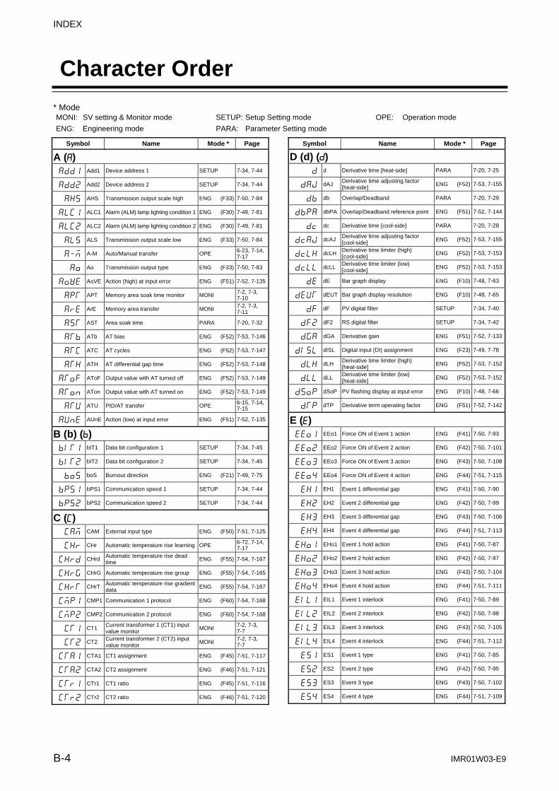
INDEX
B-4 IMR01W03-E9
Character Order
Symbol Name Mode * Page
A (A)
Add1 Add1 Device address 1 SETUP 7-34, 7-44
Add2 Add2 Device address 2 SETUP 7-34, 7-44
AHS AHS Transmission output scale high ENG (F33) 7-50, 7-84
ALC1 ALC1 Alarm (ALM) lamp lighting condition 1 ENG (F30) 7-49, 7-81
ALC2 ALC2 Alarm (ALM) lamp lighting condition 2 ENG (F30) 7-49, 7-81
ALS ALS Transmission output scale low ENG (F33) 7-50, 7-84
A-M A-M Auto/Manual transfer OPE 6-23, 7-14, 7-17
Ao Ao Transmission output type ENG (F33) 7-50, 7-83
AoVE AoVE Action (high) at input error ENG (F51) 7-52, 7-135
APT APT Memory area soak time monitor MONI 7-2, 7-3, 7-10
ArE ArE Memory area transfer MONI 7-2, 7-3, 7-11
AST AST Area soak time PARA 7-20, 7-32
ATb ATb AT bias ENG (F52) 7-53, 7-146
ATC ATC AT cycles ENG (F52) 7-53, 7-147
ATH ATH AT differential gap time ENG (F52) 7-53, 7-148
AToF AToF Output value with AT turned off ENG (F52) 7-53, 7-149
ATon ATon Output value with AT turned on ENG (F52) 7-53, 7-149
ATU ATU PID/AT transfer OPE 6-15, 7-14, 7-15
AUnE AUnE Action (low) at input error ENG (F51) 7-52, 7-135
B (b) (b)
bIT1 bIT1 Data bit configuration 1 SETUP 7-34, 7-45
bIT2 bIT2 Data bit configuration 2 SETUP 7-34, 7-45
boS boS Burnout direction ENG (F21) 7-49, 7-75
bPS1 bPS1 Communication speed 1 SETUP 7-34, 7-44
bPS2 bPS2 Communication speed 2 SETUP 7-34, 7-44
C (C)
CAM CAM External input type ENG (F50) 7-51, 7-125
CHr CHr Automatic temperature rise learning OPE 6-72, 7-14, 7-17
CHrd CHrd Automatic temperature rise dead time
ENG (F55) 7-54, 7-167
CHrG CHrG Automatic temperature rise group ENG (F55) 7-54, 7-165
CHrT CHrT Automatic temperature rise gradient data
ENG (F55) 7-54, 7-167
CMP1 CMP1 Communication 1 protocol ENG (F60) 7-54, 7-168
CMP2 CMP2 Communication 2 protocol ENG (F60) 7-54, 7-168
CT1 CT1 Current transformer 1 (CT1) input value monitor
MONI 7-2, 7-3, 7-7
CT2 CT2 Current transformer 2 (CT2) input value monitor
MONI 7-2, 7-3, 7-7
CTA1 CTA1 CT1 assignment ENG (F45) 7-51, 7-117
CTA2 CTA2 CT2 assignment ENG (F46) 7-51, 7-121
CTr1 CTr1 CT1 ratio ENG (F45) 7-51, 7-116
CTr2 CTr2 CT2 ratio ENG (F46) 7-51, 7-120
Symbol Name Mode * Page
D (d) (d)
d d Derivative time [heat-side] PARA 7-20, 7-25
dAJ dAJ Derivative time adjusting factor [heat-side]
ENG (F52) 7-53, 7-155
db db Overlap/Deadband PARA 7-20, 7-29
dbPA dbPA Overlap/Deadband reference point ENG (F51) 7-52, 7-144
dc dc Derivative time [cool-side] PARA 7-20, 7-28
dcAJ dcAJDerivative time adjusting factor [cool-side]
ENG (F52) 7-53, 7-155
dcLH dcLHDerivative time limiter (high) [cool-side]
ENG (F52) 7-53, 7-153
dcLL dcLLDerivative time limiter (low) [cool-side]
ENG (F52) 7-53, 7-153
dE dE Bar graph display ENG (F10) 7-48, 7-63
dEUT dEUT Bar graph display resolution ENG (F10) 7-48, 7-65
dF dF PV digital filter SETUP 7-34, 7-40
dF2 dF2 RS digital filter SETUP 7-34, 7-42
dGA dGA Derivative gain ENG (F51) 7-52, 7-133
dISL dISL Digital input (DI) assignment ENG (F23) 7-49, 7-78
dLH dLH Derivative time limiter (high) [heat-side]
ENG (F52) 7-53, 7-152
dLL dLL Derivative time limiter (low) [heat-side]
ENG (F52) 7-53, 7-152
dSoP dSoP PV flashing display at input error ENG (F10) 7-48, 7-66
dTP dTP Derivative term operating factor ENG (F51) 7-52, 7-142
E (E)
EEo1 EEo1 Force ON of Event 1 action ENG (F41) 7-50, 7-93
EEo2 EEo2 Force ON of Event 2 action ENG (F42) 7-50, 7-101
EEo3 EEo3 Force ON of Event 3 action ENG (F43) 7-50, 7-108
EEo4 EEo4 Force ON of Event 4 action ENG (F44) 7-51, 7-115
EH1 EH1 Event 1 differential gap ENG (F41) 7-50, 7-90
EH2 EH2 Event 2 differential gap ENG (F42) 7-50, 7-99
EH3 EH3 Event 3 differential gap ENG (F43) 7-50, 7-106
EH4 EH4 Event 4 differential gap ENG (F44) 7-51, 7-113
EHo1 EHo1 Event 1 hold action ENG (F41) 7-50, 7-87
EHo2 EHo2 Event 2 hold action ENG (F42) 7-50, 7-97
EHo3 EHo3 Event 3 hold action ENG (F43) 7-50, 7-104
EHo4 EHo4 Event 4 hold action ENG (F44) 7-51, 7-111
EIL1 EIL1 Event 1 interlock ENG (F41) 7-50, 7-89
EIL2 EIL2 Event 2 interlock ENG (F42) 7-50, 7-98
EIL3 EIL3 Event 3 interlock ENG (F43) 7-50, 7-105
EIL4 EIL4 Event 4 interlock ENG (F44) 7-51, 7-112
ES1 ES1 Event 1 type ENG (F41) 7-50, 7-85
ES2 ES2 Event 2 type ENG (F42) 7-50, 7-95
ES3 ES3 Event 3 type ENG (F43) 7-50, 7-102
ES4 ES4 Event 4 type ENG (F44) 7-51, 7-109
* Mode MONI: SV setting & Monitor mode SETUP: Setup Setting mode OPE: Operation mode
ENG: Engineering mode PARA: Parameter Setting mode

INDEX
IMR01W03-E9 B-5
Symbol Name Mode * Page
EV1 EV1 Event 1 set value (EV1) PARA 7-20, 7-21
EV2 EV2 Event 2 set value (EV2) PARA 7-20, 7-21
EV3 EV3 Event 3 set value (EV3) PARA 7-20, 7-21
EV4 EV4 Event 4 set value (EV4) PARA 7-20, 7-21
EVM1 EVM1 Event monitor 1 MONI 7-2, 7-3, 7-8
EVM2 EVM2 Event monitor 2 MONI 7-2, 7-3, 7-8
EVT1 EVT1 Event 1 delay timer ENG (F41) 7-50, 7-91
EVT2 EVT2 Event 2 delay timer ENG (F42) 7-50, 7-100
EVT3 EVT3 Event 3 delay timer ENG (F43) 7-50, 7-107
EVT4 EVT4 Event 4 delay timer ENG (F44) 7-51, 7-114
EXC EXC Energized/De-energized ENG (F30) 7-49, 7-80
F (F)
Fn Fn Direct key type ENG (F11) 7-48, 7-68
Fn1 Fn1 Direct key 1 ENG (F11) 7-48, 7-67
Fn2 Fn2 Direct key 2 ENG (F11) 7-48, 7-67
Fn3 Fn3 Direct key 3 ENG (F11) 7-48, 7-68
H (H)
HbA1 HbA1 Heater break alarm 1 (HBA1) set value SETUP 7-34, 7-35
HbA2 HbA2 Heater break alarm 2 (HBA2) set value SETUP 7-34, 7-35
HbC1 HbC1 Number of heater break alarm 1 (HBA1) delay times ENG (F45) 7-51, 7-119
HbC2 HbC2 Number of heater break alarm 2 (HBA2) delay times ENG (F46) 7-51, 7-122
HbH1 HbH1 Heater melting determination point 1 SETUP 7-34, 7-39
HbH2 HbH2 Heater melting determination point 2 SETUP 7-34, 7-39
HbL1 HbL1 Heater break determination point 1 SETUP 7-34, 7-38
HbL2 HbL2 Heater break determination point 2 SETUP 7-34, 7-38
HbS1 HbS1 Heater break alarm 1 (HBA1) type ENG (F45) 7-51, 7-117
HbS2 HbS2 Heater break alarm 2 (HBA2) type ENG (F46) 7-51, 7-122
HEAT HEAT Power feed forward input value monitor ENG (F91) 7-54, 7-172
I (I)
I I Integral time [heat-side] PARA 7-20, 7-25
IAJ IAJ Integral time adjusting factor [heat-side] ENG (F52) 7-53, 7-156
Ic Ic Integral time [cool-side] PARA 7-20, 7-27
IcAJ IcAJ Integral time adjusting factor [cool-side] ENG (F52) 7-53, 7-156
IcLH IcLH Integral time limiter (high) [cool-side] ENG (F52) 7-53, 7-154
IcLL IcLL Integral time limiter (low) [cool-side] ENG (F52) 7-53, 7-154
IddP IddP Integral/derivative time decimal point position ENG (F51) 7-52, 7-133
ILH ILH Integral time limiter (high) [heat-side] ENG (F52) 7-53, 7-151
ILL ILL Integral time limiter (low) [heat-side] ENG (F52) 7-53, 7-151
ILr ILr Interlock release MONI 7-2, 7-3, 7-13
InP InP Input type ENG (F21) 7-49, 7-69
InT1 InT1 Interval time 1 SETUP 7-34, 7-46
InT2 InT2 Interval time 2 SETUP 7-34, 7-46
Symbol Name Mode * Page
L (L)
LbA LbA Control loop break alarm (LBA) time PARA 7-20, 7-22
Lbd Lbd LBA deadband PARA 7-20, 7-23
LCK LCK Set lock level SETUP 7-34, 7-47
LnKA LnKA Link area number PARA 7-20, 7-33
LoGC LoGC Output assignment ENG (F30) 7-49, 7-79
M (M)
MCH MCH Master channel selection ENG (F50) 7-51, 7-126
MoT MoT Control motor time ENG (F53) 7-53, 7-161
Mr Mr Manual reset PARA 7-20, 7-30
MV MV Manipulated output value (MV1) monitor [heat-side] MONI 7-2, 7-3,
7-9
MV2 MV2 Manipulated output value (MV2) monitor [cool-side] MONI 7-2, 7-3,
7-10
MVTS MVTS MV transfer function ENG (F50) 7-51, 7-128
O (o) (o)
oHH oHH ON/OFF action differential gap (upper) ENG (F51) 7-52, 7-134
oHL oHL ON/OFF action differential gap (lower) ENG (F51) 7-52, 7-134
oLA oLA Integrated output limiter ENG (F53) 7-53, 7-161
oLH oLH Output limiter high (MV1) ENG (F51) 7-52, 7-138
oLH2 oLH2 Output limiter high (MV2) ENG (F51) 7-52, 7-138
oLL oLL Output limiter low (MV1) ENG (F51) 7-52, 7-138
oLL2 oLL2 Output limiter low (MV2) ENG (F51) 7-52, 7-138
ord ord Output change rate limiter (down) [MV1] ENG (F51) 7-52, 7-137
ord2 ord2 Output change rate limiter (down) [MV2] ENG (F51) 7-52, 7-137
orU orU Output change rate limiter (up) [MV1] ENG (F51) 7-52, 7-137
orU2 orU2 Output change rate limiter (up) [MV2] ENG (F51) 7-52, 7-137
oS oS Control action ENG (F51) 7-52, 7-129
oTT1 oTT1 Timer 1 ENG (F30) 7-49, 7-80
oTT2 oTT2 Timer 2 ENG (F30) 7-49, 7-80
oTT3 oTT3 Timer 3 ENG (F30) 7-49, 7-80
oTT4 oTT4 Timer 4 ENG (F30) 7-49, 7-80
P (P)
P P Proportional band [heat-side] PARA 7-20, 7-24
PAJ PAJ Proportional band adjusting factor [heat-side] ENG (F52) 7-53, 7-156
Pb Pb PV bias SETUP 7-34, 7-40
Pc Pc Proportional band [cool-side] PARA 7-20, 7-27
PcAJ PcAJ Proportional band adjusting factor [cool-side] ENG (F52) 7-53, 7-156
PcLH PcLH Proportional band limiter (high) [cool-side] ENG (F52) 7-53, 7-153
PcLL PcLL Proportional band limiter (low) [cool-side] ENG (F52) 7-53, 7-153
Pd Pd Hot/Cold start ENG (F50) 7-51, 7-123
PdA PdA Start determination point ENG (F50) 7-51, 7-124
PFF PFF Power feed forward selection ENG (F51) 7-52, 7-140
PFFS PFFS Power feed forward gain ENG (F51) 7-52, 7-141
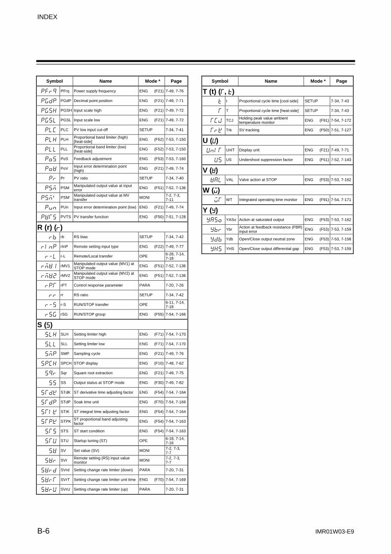
INDEX
B-6 IMR01W03-E9
Symbol Name Mode * Page
PFrq PFrq Power supply frequency ENG (F21) 7-49, 7-76
PGdP PGdP Decimal point position ENG (F21) 7-49, 7-71
PGSH PGSH Input scale high ENG (F21) 7-49, 7-72
PGSL PGSL Input scale low ENG (F21) 7-49, 7-72
PLC PLC PV low input cut-off SETUP 7-34, 7-41
PLH PLH Proportional band limiter (high) [heat-side] ENG (F52) 7-53, 7-150
PLL PLL Proportional band limiter (low) [heat-side] ENG (F52) 7-53, 7-150
PoS PoS Feedback adjustment ENG (F53) 7-53, 7-160
PoV PoV Input error determination point (high) ENG (F21) 7-49, 7-74
Pr Pr PV ratio SETUP 7-34, 7-40
PSM PSM Manipulated output value at input error ENG (F51) 7-52, 7-136
PSM` PSM’ Manipulated output value at MV transfer MONI 7-2, 7-3,
7-11
Pun PUn Input error determination point (low) ENG (F21) 7-49, 7-74
PVTS PVTS PV transfer function ENG (F50) 7-51, 7-128
R (r) (r)
rb rb RS bias SETUP 7-34, 7-42
rInP rInP Remote setting input type ENG (F22) 7-49, 7-77
r-L r-L Remote/Local transfer OPE 6-28, 7-14, 7-18
rMV1 rMV1 Manipulated output value (MV1) at STOP mode ENG (F51) 7-52, 7-136
rMV2 rMV2 Manipulated output value (MV2) at STOP mode ENG (F51) 7-52, 7-136
rPT rPT Control response parameter PARA 7-20, 7-26
rr rr RS ratio SETUP 7-34, 7-42
r-S r-S RUN/STOP transfer OPE 6-11, 7-14, 7-18
rSG rSG RUN/STOP group ENG (F55) 7-54, 7-166
S (S)
SLH SLH Setting limiter high ENG (F71) 7-54, 7-170
SLL SLL Setting limiter low ENG (F71) 7-54, 7-170
SMP SMP Sampling cycle ENG (F21) 7-49, 7-76
SPCH SPCH STOP display ENG (F10) 7-48, 7-62
Sqr Sqr Square root extraction ENG (F21) 7-49, 7-75
SS SS Output status at STOP mode ENG (F30) 7-49, 7-82
STdK STdK ST derivative time adjusting factor ENG (F54) 7-54, 7-164
STdP STdP Soak time unit ENG (F70) 7-54, 7-169
STIK STIK ST integral time adjusting factor ENG (F54) 7-54, 7-164
STPK STPK ST proportional band adjusting factor ENG (F54) 7-54, 7-163
STS STS ST start condition ENG (F54) 7-54, 7-163
STU STU Startup tuning (ST) OPE 6-18, 7-14, 7-16
SV SV Set value (SV) MONI 7-2, 7-3, 7-7
SVr SVr Remote setting (RS) input value monitor MONI 7-2, 7-3,
7-7
SVrd SVrd Setting change rate limiter (down) PARA 7-20, 7-31
SVrT SVrT Setting change rate limiter unit time ENG (F70) 7-54, 7-169
SVrU SVrU Setting change rate limiter (up) PARA 7-20, 7-31
Symbol Name Mode * Page
T (t) (T, t)
t t Proportional cycle time [cool-side] SETUP 7-34, 7-43
T T Proportional cycle time [heat-side] SETUP 7-34, 7-43
TCJ TCJ Holding peak value ambient temperature monitor ENG (F91) 7-54, 7-172
TrK Trk SV tracking ENG (F50) 7-51, 7-127
U (U)
UnIT UnIT Display unit ENG (F21) 7-49, 7-71
US US Undershoot suppression factor ENG (F51) 7-52, 7-143
V (V)
VAL VAL Valve action at STOP ENG (F53) 7-53, 7-162
W (W)
WT WT Integrated operating time monitor ENG (F91) 7-54, 7-171
Y (Y)
YASo YASo Action at saturated output ENG (F53) 7-53, 7-162
Ybr Ybr Action at feedback resistance (FBR) input error ENG (F53) 7-53, 7-159
Ydb Ydb Open/Close output neutral zone ENG (F53) 7-53, 7-158
YHS YHS Open/Close output differential gap ENG (F53) 7-53, 7-159

IMR01W03-E9 1
Revisions
Date of Revision Manual Number Reason for Revision
April, 2005 IMR01W03-E1 The first edition issue
August, 2005 IMR01W03-E2 Addition of description:
Automatic power frequency detection function by CT input P. 1-12, P. 7-75, P. 9-4 Correspondence of startup tuning to Heat/Cool control P. 6-18, P. 6-19, P. 7-16 Correspondence of automatic temperature rise learning function to Heat/Cool control
P. 6-73, P. 6-74, P. 7-17 Setting example of bar graph display resolution P. 7-65 Hot/Cold start action change P. 6-39 Description of action (high/low) at input error P. 7-135 Factory set value change: Start determination point P. 7-124, P. A-18 Open/Close output neutral zone P. 7-156, P. A-21 Open/Close output differential gap P. 7-157, P. A-21 Revision of clerical errors: “Output value when power failure recovers” at Hot start 2 in Auto mode
P. 6-39, P. 7-123
September, 2008 IMR01W03-E3 Overall revision
July, 2009 IMR01W03-E4 Addition of description:
Direct action of Position proportioning PID control P. 1-4, P. 7-58, P. 7-129, P. A-20
Overlap/Deadband reference point P. 7-52, P. 7-144, P. 9-9, P. A-21 Action at saturated output P. 6-40, P. 6-41, P. 6-43, P. 6-46, P. 6-47,
P. 7-53, P. 7-131, P. 7-162, P. 9-11, P. A-22 Exception of key operation P. 5-2, P. 6-48, P. 7-54, P. 7-160, P. 7-172 Change of description: State of STOP mode P. 6-11 Factory set value change: Heater break alarm 1 (HBA1) type P. 7-37, P. 7-117, P. 7-122, P. A-19
IMR01W03-E5 Intentionally unused (This version number is not used in English version to match the versions between Japanese and English versions.)
December, 2010 IMR01W03-E6 Revised due to change of terminal cover shape and model code as well as corrections of errors.
August, 2012 IMR01W03-E7 Updated for the latest version of the OS: P. 1-2, P. 1-15
Added Communication tool PROTEM2: P. 1-15
Added comment to Termination resistor: P. 4-13
Changed the data range of "Manipulated output value at MV transfer" in Heat/Cool PID control: P. 7-11, P. 9-9, P. A-10
Added comment to Force ON of Event 4 action: P. 7-115
December, 2015 IMR01W03-E8 Change of compliance mark. (C-Tick → RCM) P. 9-17
October, 2016 IMR01W03-E9 Added a new range code: P. 1-5
Changed the address in the setting example of Master channel selection: P. 7-126
Deleted unnecessary part: P. 9-13

IMR01W03-E9 2
MEMO

The first edition: APR. 2005 [IMQ00]The ninth edition: OCT. 2016 [IMQ00]

IMR01W03-E9 OCT. 2016
RKC INSTRUMENT INC.
HEADQUARTERS: 16-6, KUGAHARA 5-CHOME, OHTA-KU TOKYO 146-8515 JAPAN PHONE: 03-3751-9799 (+81 3 3751 9799) FAX: 03-3751-8585 (+81 3 3751 8585) E-mail: [email protected] Website: http://www.rkcinst.com/
R