fault ride-through capability enhancement for grid ...direct current dc converter, a capacitor cc...
TRANSCRIPT
International Journal of Technical Innovation in Modern
Engineering & Science (IJTIMES) Impact Factor: 5.22 (SJIF-2017), e-ISSN: 2455-2585
Volume 4, Issue 7, July-2018
IJTIMES-2018@All rights reserved 736
Fault Ride-Through Capability Enhancement for grid integrated Photovoltaic
system with Continuous mixed P-Norm
1Dipak Soni,
2 Dr. Samina Elyas Mubeen
1PG Scholar,
2H.O.D
1, 2 Department of Electrical and Electronics Engineering, Radharaman Engineering College, Bhopal (M.P)
ABSTRACT
This document presents a new application of the method versatile control based on the continuous calculation of
mixed type (CMPN) motivated to improve the transport capacity under tension photovoltaic control (PV) associated
with the frame (LVRT) enhancement facilities. PV clusters are connected to the common junction point (CCP) via a
direct current DC converter, a capacitor CC interface, an inverter side matrix and a three phase transformer. The
DC-DC converter is used for a higher power point after processing in view of the fragmentary open circuit voltage
technique. The inverter on the matrix side is used to control the DC connection voltage and terminal voltage on the
PCC via a vector control diagram. The necessary versatile necessary controller (PI) based on the CMPN calculation
is used to control the electronic circuits due to the fast connection. The implemented calculation is updated, the PI
controller increases online without having to calibrate or simplify. The feasibility of the procedure performed
steering contrasts with the approach Taguchi based on ideal PI controller, so that patient deemed due to the
presence of a fault the table asymmetric symmetric errors and incorrect reconnection circuit breakers permanently.
The legitimacy of the versatile control technique is largely determined by reproduction, complete with the
programming of MATLAB / Simulink. The LVRT capacity of the frame can be improved by implementing the
versatile controlled photovoltaic control systems.
Keywords:Adaptive control, low voltage ride through (LVRT), photovoltaic (PV) power systems, power system
control, power system dynamic stability.
1. INTRODUCTION
As an important part of modern energy infrastructure, distributed systems for renewable energy (DRE) have
developed at an accelerated pace. In recent years, photovoltaic solar energy markets have been particularly flourishing,
particularly due to the continuous fall in the price of the photovoltaic module (PV) and the strong global demand for
environmentally friendly energy conversion systems. The capacity of photovoltaic solar energy improved by 25% in 2014 (ie
about 50 GW), which represents a total of 227 GW. The annual promotion in 2015 was almost 10 times the cumulative
capacity of photovoltaic solar energy in the last decade.
In the future, DRE systems will convince the needs of the generation closest to the consumption points. However, due to
the rapid growth of distributed generations of renewable energy, stability and security have attracted a lot of attention. To
face the challenge due to a phase of high saturation of photovoltaic systems, various research activities have been carried out
to promote the combination of photovoltaic systems. In summary, it can be expected that the photovoltaic systems that are
compatible with the network are multifunctional. This means that photovoltaic systems require reactive power control,
maximum power tracking (MPPT), island fault detection, harmonic compensation and fault operation (FRT).
Some photovoltaic energy systems in the current market can already provide such services. However, photovoltaic
frames must be better in light of network security, unbreakable quality and high level security. A direct impression of the
expansion of applications for photovoltaic frameworks is that many countries have updated or reconsidered the control of
national networks, so that distributed generations need advanced network error management functions. As indicated by the
needs, the photovoltaic frames must remain connected to the deficiencies of the network and, if requested, offer a response.
This is also called low voltage passing capacity (LVRT). In scandalous cases, that is, the voltage of the matrix drops to
zero and the separation of the network is not allowed within a predefined short time interval (for example 150 ms), the
possibility to continue from zero voltage (ZVRT) . Similarly, photovoltaic frames under zero voltage conditions should also
improve the restoration of the network using sensitive current infusion methods.

International Journal of Technical Innovation in Modern Engineering & Science (IJTIMES) Volume 4, Issue 7, July-2018, e-ISSN: 2455-2585,Impact Factor: 5.22 (SJIF-2017)
IJTIMES-2018@All rights reserved 737
Although the ZVRT operation can be considered as a single instance of LVRT, a more specific control method must be
performed in the middle of the FRT operation. Particularly in the associated single-phase network photovoltaic frames, when
the error occurs, the frames still blow the sinusoidal feedback current to support the crystal lattice without matrix data.
Testing problems for ZVRT that quickly distinguish the recording in a single step of the network voltage in the PV array, the
ZVRT operation mode does not change the data network and the error, fast synchronization without causing a current
overheat protection.
As mentioned above, it is required that the VF framework associated with the single-stage matrix operate in different
ways in a precise and rapid manner in confusing circumstances. The calculations are used to solve different separations of
versatile technical problems in different applications, such as signal processing, electronics, audio, voice and voice
applications. Recently, these algorithms were examined in electric power systems, because a related projection algorithm was
used to adjust the parameters of the PI controller in a wind energy conversion system. These algorithms must take into
account a compromise between the complexity of the algorithm and the speed of convergence. Many comparisons have been
made between the implemented CMPN algorithm and other adaptive filtering algorithms. The results have demonstrated the
high binding speed of the calculation of CMPN in these calculations for different applications.
In this paper, a new use of a versatile control method based on the calculation of CMPN improves the power of the PVR
control PVRT connected to the installation. The DC-DC media converter is used for a tracking operation of the maximum
power in view of the non-zero partial voltage strategy. The inverter side of the network is used to monitor the voltage of the
DC interface.
II. SYSTEM ARCHITECTURE
In the low-voltage DRE system, the single-phase configuration is a more competitive solution. Figure 1 shows a generic
control structure of the single-phase PV system connected to the network, with an option of a DC-DC converter, which is
used to increase the voltage of the photovoltaic panel to an appropriate level of the DC converter of the next stage AC The
choice of one or two phases (ie without or with the DC-DC converter) depends on the control strategy, efficiency, cost, size
and weight, etc. To ensure a sinusoidal network flow of high quality, the inductor is used the capacitor-inducing filter (LCL)
is used to improve the switching harmonics with lighter and smaller inductors.
Fig: 1. Generic control structure of the single-phase grid connected photovoltaic (PV) system. Maximum power point
tracking (MPPT).
Under normal circumstances, the photovoltaic framework extracts the most extreme current from the photovoltaic screens (ie
in the MPPT operation) and exchanges it with the matrix in a solidarity control factor by means of a control system. The
control procedure that is often used in single-stage inverters has two circles of fall control. The inner circle is a current circle
in which the quality of the network flow can be guaranteed and the current security is also guaranteed. The outer circle is a
circle of voltage or power control, where the DC-side voltage can be guaranteed and a reference of the inner current circle is
determined simultaneously in the outer circle.
The PV clusters are connected to the transport 18 of the test frame via a DC-DC converter, a 15 mF DC interface capacitor, a
grid-side inverter, three-stage converter transformers and current lines. Double circuit transmission, as shown in Fig: 2.
This system is considered a compact version of the original New England system and is used to study realistic answers. The
IEEE 39 bus system comprises 39 buses, 19 of which are cargo buses. There are 10 generators in the system. The bus 31 to
which the generator 2 is connected is defined as the slack bus. The total load and generation of the system are respectively
6098.1 and 6140.81 MW. The load model is considered as a constant and constant current supply load. To test the
photovoltaic power plant with the IEEE 39 bus system, the photovoltaic power plant is connected to bus 18.
International Journal of Technical Innovation in Modern Engineering & Science (IJTIMES) Volume 4, Issue 7, July-2018, e-ISSN: 2455-2585,Impact Factor: 5.22 (SJIF-2017)
IJTIMES-2018@All rights reserved 738
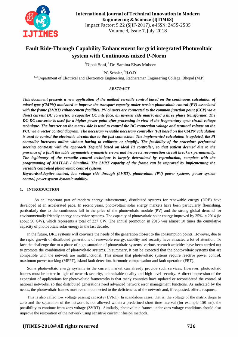
Fig. 2. Grid Connected PV power plant
A DC-DC boost converter is used to control the output voltage of the PV plant to meet the maximum output power level.
This is done by controlling the duty cycle of the isolated gate bipolar transistor (IGBT) switch of the transducer as shown in
FIG. 3. The fractional open-circuit voltage method is used to meet the maximum power condition.
Fig. 3. Control of the DC-DC converter
A CMPN-Based adaptive PI controller is used for this target The output signal from the controller is compared to a triangular
carrier waveform signal with a frequency of 4 kHz to generate the trigger pulses from the IGBT switch. In this study an
inverter of IGBT switches of six levels and three phases has been implemented. The grid-side inverter is used to control the
intermediate circuit voltage and terminal voltage on the PCC via a vector control circuit as illustrated in Fig: 4.
Adaptive PI drivers based on CMPN algorithms have been developed for this purpose. A phase-locked loop (PLL) is
intended to detect the transformation angle of the three-phase voltages in the PCC.
A family of adaptive filter algorithms are adaptive mixed-choice filters that have different forms. The adaptive filter was
presented with the mixed standard (LMMN) with lower mean value, in which the least squares mean (LMS) and the least
average quartiles (LMF) algorithms were combined. In addition, a robust mixed-standard (RMN) algorithm is implemented
and the LMS algorithm combines with the minimal absolute deviation algorithm (LAD).
Fig. 4. Control block diagram of the grid-side inverter.

International Journal of Technical Innovation in Modern Engineering & Science (IJTIMES) Volume 4, Issue 7, July-2018, e-ISSN: 2455-2585,Impact Factor: 5.22 (SJIF-2017)
IJTIMES-2018@All rights reserved 739
Next, a normalized NMR algorithm as soon as the grid-to-ground error is detected by the network synchronization, the
photovoltaic system (PV) must switch to the operational mode of network failure with reactive energy injection to restore the
network. In several countries, the correct network code has been implemented to meet different local conditions under
national conditions. Figure 5 shows an example of the voltage profiles for the possible fault condition in some countries,
where photovoltaic systems must operate under specific circumstances when the mains voltage is above the curves.
Fig: 5. Low-voltage (and zero-voltage) ride-through requirements for grid-connected systems in different countries.
Fig: 6. Reactive current injection requirements under lowvoltage ride-through/zero-voltage ride-through (LVRT/ZVRT)
operations.
III. SYSTEM MODELING
A. System Model
In this section, the system consists of photovoltaic panels connected to the network via double transmission lines and three
phase step transformer. Electronic power circuits, such as the DC-DC boost converter and the grid-side inverter, are used to
integrate the photovoltaic system with the electricity grid. The network under investigation is the New England IEEE 39 bus
testing system, consisting of 10 generator buses (generator 2 on bus 31 is considered a weak bus) with 19 charging sockets.
For better understanding, the PV module is displayed as a combination of diode resistance, as shown in Figure 1. The basic
features of I-V [19-21].
Fig: 7.Basic PV Module
(1)
Where𝐼𝑃𝑉 is the current obtained from the photovoltaic module which is based on solar irradiation and temperature, 𝐼0 is the
reverse saturation current of the diode, 𝑅𝑝 and 𝑅𝑆 are the parallel and series resistances, is the ideality factor of the diode,
and 𝑉𝑡is the thermal voltage of the PV module.
International Journal of Technical Innovation in Modern Engineering & Science (IJTIMES) Volume 4, Issue 7, July-2018, e-ISSN: 2455-2585,Impact Factor: 5.22 (SJIF-2017)
IJTIMES-2018@All rights reserved 740
The photovoltaic current can be mathematically expresses as:
(2)
where 𝐼𝑃𝑉,𝑛 is the nominal current value of the PV module, 𝐾𝐼 is the short circuit current per temperature coefficient, 𝛥𝑇 is
the residue of the actual and nominal temperatures with G and 𝐺𝑛 as the actual and nominal values of the solar irradiation on
the surface of the module[19]. 𝐼𝑃𝑉, and 𝐼0 can be expressed mathematically [22] as follows:
(3)
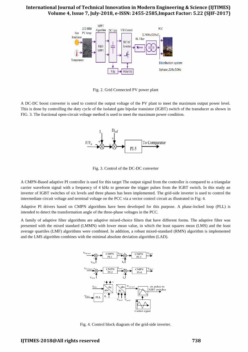
Fig: 8. characteristics of 2.5 MW Power Plant
Where 𝐼𝑆𝐶, is the short circuit nominal current and 𝑉𝑜𝑐, is the open circuit nominal voltage with KV being the coefficient of
open circuit voltage per temperature.
The characteristics of a 2.5 MW Photo voltaic power plant are depicted in figure 8.
B. Modeling of Power Electronic circuits
DC-DC Boost Converter:
A DC-DC boost converter is incorporated to limit the output voltage of the power plant in order to satisfy the maximum
output power condition by controlling the duty cycle of IGBT switch.
Where KM is a constant gain VOC-pilot is the open circuit voltage of the pilot module and V0 being the output voltage of
the converter Grid side inverter.
In order to control the DC link voltage and the terminal voltage at the point of common coupling (PCC), a two level three
phase six IGBT switches inverter is utilized. A phase locked loop (PLL) is used to detect the transformation angle from the
three phase voltages at the point of common coupling with the DC link voltage being maintained constant at 1.2 KV.
IV.CONTROL TECHNIQUES
A. Continuous Mixed P-Norm Technique
Continuous Mixed P-Norm algorithm is one of the robust mixed norm algorithm in the family of adaptive filtering
algorithms. The CMPN algorithm based adaptive PI controllers are developed to limit the voltages at the dc link and that at
the PCC through a vector control scheme. Mixed P-Norm algorithm has the combined benefits of p-norm and least mean
square(LMS) algorithm. The CMPN algorithm can be mathematically defined as follows[18]:
(6)
Where (𝑝) is a probability density weighting function with the following constraint imposed on it.
(7)

International Journal of Technical Innovation in Modern Engineering & Science (IJTIMES) Volume 4, Issue 7, July-2018, e-ISSN: 2455-2585,Impact Factor: 5.22 (SJIF-2017)
IJTIMES-2018@All rights reserved 741
The weight vector of the algorithm is updated according to the formula given below:
(𝑘 + 1) = (𝑘) − (𝑘)𝐽(𝑘) (8)
Where is the step size and 𝛻𝑤(𝑘)(𝑘) is the instantaneous gradient of J(k) with respect to 𝑤(𝑘).
B. Proportional Resonant Controller
In proportional controller the output is proportional to the error signal. The proportional resonant controller is one of the most
popular controllers used to regulate the injected current into the grid. The PR controller can overcome few drawbacks of the
proportional integral controller. A PR controller is a combination of a proportional term and a resonant term which can be
expressed mathematically as:
Where is the resonant frequency In order to improve the performance by handling harmonics a harmonic compensator is
incorporated. this harmonic compensator can be expressed as:
Where h is the order of the harmonic. A proportional resonant controller is adopted in stationary reference frame for inverter
controller. However, it can be easily implemented in the frame as well.
V. SIMULATION RESULTS & DISCUSSION
System Analysis under Fault
The detailed model of a grid-connected PV power plant is presented. The model involves a complete switching model of the
power electronic circuits with the implemented adaptive control strategy for obtaining realistic responses. The simulation
results are performed using the powerful power system computer aided design (MATLAB/SIMULINK) software.
Fig.9. Simulink model for Adaptive control PI
A. Unsymmetrical Faults
The designed system is subjected to line-to-ground (LG), double line-to-ground (LL) and double line-to-ground (LLG)
faults and the results obtained are analyzed for each control strategy. The fault conditions are defined to occur at any instant
when t = 0.05 sec with a duration of 0.1 sec. The point of fault in the system is shown in figure 10 and is represented by point
F.
Fig. 10: Connection of PV to Grid

International Journal of Technical Innovation in Modern Engineering & Science (IJTIMES) Volume 4, Issue 7, July-2018, e-ISSN: 2455-2585,Impact Factor: 5.22 (SJIF-2017)
IJTIMES-2018@All rights reserved 742
System subjected to fault is simulated in MATLAB/ SIMULINK and the results obtained are illustrated in the graph given
below.
Fig: 11: Single Line to Ground Fault
Fig: 12: Line to line fault
Fig: 13: Line to Line to Ground Fault
The voltage at the point of common coupling is observed in each case.
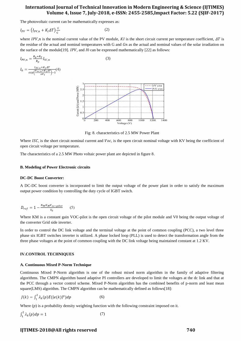
B. Symmetrical Faults
The symmetrical faults imposed on the system are three phase temporary fault and three phase permanent fault. Since the
Duration of the fault is for a considerable time, i.e., the fault occurs at the instant t=0.05 and the duration is assumed to be
0.69 sec.
(a)
International Journal of Technical Innovation in Modern Engineering & Science (IJTIMES) Volume 4, Issue 7, July-2018, e-ISSN: 2455-2585,Impact Factor: 5.22 (SJIF-2017)
IJTIMES-2018@All rights reserved 743
(b)
(c)
Fig: 14: Three phase permanent fault (a) Voltage at the PCC; (b) Real Power and; (c) Reactive Power
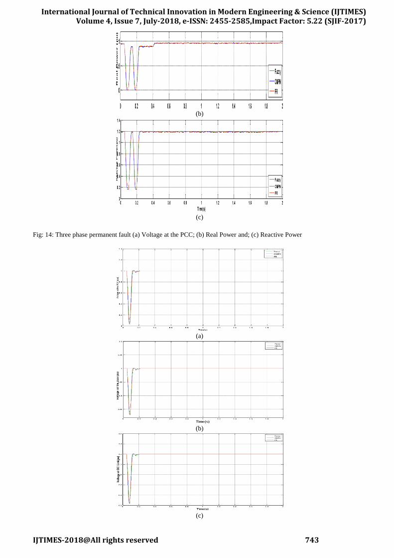
(a)
(b)
(c)
International Journal of Technical Innovation in Modern Engineering & Science (IJTIMES) Volume 4, Issue 7, July-2018, e-ISSN: 2455-2585,Impact Factor: 5.22 (SJIF-2017)
IJTIMES-2018@All rights reserved 744
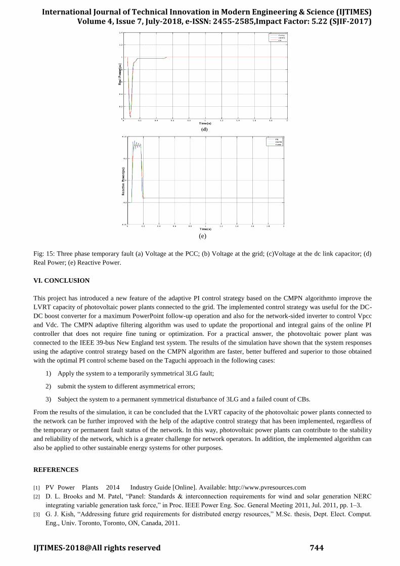
(e)
Fig: 15: Three phase temporary fault (a) Voltage at the PCC; (b) Voltage at the grid; (c)Voltage at the dc link capacitor; (d)
Real Power; (e) Reactive Power.
VI. CONCLUSION
This project has introduced a new feature of the adaptive PI control strategy based on the CMPN algorithmto improve the
LVRT capacity of photovoltaic power plants connected to the grid. The implemented control strategy was useful for the DC-
DC boost converter for a maximum PowerPoint follow-up operation and also for the network-sided inverter to control Vpcc
and Vdc. The CMPN adaptive filtering algorithm was used to update the proportional and integral gains of the online PI
controller that does not require fine tuning or optimization. For a practical answer, the photovoltaic power plant was
connected to the IEEE 39-bus New England test system. The results of the simulation have shown that the system responses
using the adaptive control strategy based on the CMPN algorithm are faster, better buffered and superior to those obtained
with the optimal PI control scheme based on the Taguchi approach in the following cases:
1) Apply the system to a temporarily symmetrical 3LG fault;
2) submit the system to different asymmetrical errors;
3) Subject the system to a permanent symmetrical disturbance of 3LG and a failed count of CBs.
From the results of the simulation, it can be concluded that the LVRT capacity of the photovoltaic power plants connected to
the network can be further improved with the help of the adaptive control strategy that has been implemented, regardless of
the temporary or permanent fault status of the network. In this way, photovoltaic power plants can contribute to the stability
and reliability of the network, which is a greater challenge for network operators. In addition, the implemented algorithm can
also be applied to other sustainable energy systems for other purposes.
REFERENCES
[1] PV Power Plants 2014 Industry Guide [Online]. Available: http://www.pvresources.com
[2] D. L. Brooks and M. Patel, “Panel: Standards & interconnection requirements for wind and solar generation NERC
integrating variable generation task force,” in Proc. IEEE Power Eng. Soc. General Meeting 2011, Jul. 2011, pp. 1–3.
[3] G. J. Kish, “Addressing future grid requirements for distributed energy resources,” M.Sc. thesis, Dept. Elect. Comput.
Eng., Univ. Toronto, Toronto, ON, Canada, 2011.

International Journal of Technical Innovation in Modern Engineering & Science (IJTIMES) Volume 4, Issue 7, July-2018, e-ISSN: 2455-2585,Impact Factor: 5.22 (SJIF-2017)
IJTIMES-2018@All rights reserved 745
[4] Y. Yang, F. Blaabjerg, and Z. Zou, “Benchmarking of grid fault modes in single-phase grid-connected photovoltaic
systems,” IEEE Trans. Ind. Applicat., vol. 49, no. 5, pp. 2167–2176, Sep./Oct. 2013.
[5] Y. Yang, F. Blaabjerg, and H. Wang, “Low-voltage ride-through of single-phase transformerless photovoltaic inverters,”
IEEE Trans. Ind. Applicat., vol. 50, no. 3, pp. 1942–1952, May/Jun. 2014.
[6] K. Kawabe and K. Tanaka, “Impact of dynamic behavior of photovoltaic power generation systems on short-term
voltage stability,” IEEE Trans. Power Syst., vol. 30, no. 6, pp. 3416–3424, Nov. 2015.
[7] M. S. El Moursi, W. Xiao, and J. L. Kirtley, “Fault ride through capability for grid interfacing large scale PV power
plants,” IET Gener., Transm., Distrib., vol. 7, no. 5, pp. 1027–1036, 2013.
[8] Y. Wu, C.-H. Chang, Y. Chen, C. Liu, and Y. Chang, “A current control strategy for three-phase PV power system with
low-voltage ridethrough,” in Proc. IET Int. Conf. Advances on Power System Control, Operation, Management
(APSCOM), 2012, pp. 1–6.
[9] M. K. Hossain and M. H. Ali, “Low voltage ride through capability enhancement of grid connected PV system by
SDBR,” in Proc. IEEE PES T&D Conf. Expo., 2014, pp. 1–5.
[10] H. M. Hasanien and S. M. Muyeen, “Design optimization of controller parameters used in variable-speed wind energy
conversion system by genetic algorithms,” IEEE Trans. Sustain. Energy, vol. 3, no. 2, pp. 200–208, Apr. 2012.
[11] H. M. Hasanien and S. M. Muyeen, “A Taguchi approach for optimum design of proportional-integral controllers in
cascaded control scheme,” IEEE Trans. Power Syst., vol. 28, no. 2, pp. 1636–1644, May 2013.
[12] M. N. Ambia, H. M. Hasanien, A. Al-Durra, and S. M. Muyeen, “Harmony search algorithm-based controller parameters
optimization for a distributed-generation system,” IEEE Trans. Power Del., vol. 30, no.1, pp. 246–255, Feb. 2015.
[13] H. M. Hasanien, “Shuffled frog leaping algorithm-based static synchronous compensator for transient stability
improvement of a gridconnected wind farm,” IET Renew. Power Gener., vol. 8, no. 6, pp. 722–730, Aug. 2014.
[14] J. Ni and F. Li, “Efficient implementation of the affine projection sign algorithm,” IEEE Signal Process. Lett., vol. 19,
no. 1, pp. 24–26, Jan. 2012.
[15] L. Xiao, Y. Wang, P. Zhang, M. Wu, and J. Yang, “Variable regularisation efficient -law improved proportionate affine
projection algorithm for sparse system identification,” Electron. Lett., vol. 48, no. 3, pp. 182–184, Feb. 2012.
[16] J. M. Gil-Cacho, M. Signoretto, T. Van Waterschoot, M. Moonen, and S. H. Jensen, “Nonlinear acoustic echo
cancellation based on a slidingwindow leaky kernel affine projection algorithm,” IEEE Trans. Audio, Speech, Lang.
Process., vol. 21, no. 9, pp. 1867–1878, Sep. 2013.
[17] H. M. Hasanien, “A set-membership affine projection algorithm-based adaptive-controlled SMES units for wind farms
output power smoothing,” IEEE Trans. Sustain. Energy, vol. 5, no. 4, pp. 1226–1233, Oct. 2014.
[18] H. Zayyani, “Continuous mixed -norm adaptive algorithm for system identification,” IEEE Signal Process. Lett., vol. 21,
no. 9, pp. 1108–1110, Sep. 2014.
[19] H. M. Hasanien, “Shuffled frog leaping algorithm for photovoltaic model identification,” IEEE Trans. Sustain. Energy,
vol. 6, no. 2, pp. 509–515, Apr. 2015.
[20] Y. A. Mahmoud, W. Xiao, and H. H. Zeineldin, “A parameterization approach for enhancing PV model accuracy,” IEEE
Trans. Ind. Electron., vol. 60, no. 12, pp. 5708–5716, Dec. 2013.
[21] R. Kadri, J. P. Gaubert, and G. Champenois, “An improved maximum power point tracking for photovoltaic
gridconnected inverter based on voltage-oriented control,” IEEE Trans. Ind. Electron., vol. 58, no. 1, pp. 66–75, Jan.
2011.
[22] M. G. Villalva, J. R. Gazoli, and E. R. Filho, “Comprehensive approach to modeling and simulation of photovoltaic
arrays,” IEEE Trans. Power Electron., vol. 24, no. 5, pp. 1198–1208, May 2009.
[23] KC200GT High Efficiency Multicrystalline Photovoltaic Module Datasheet. Kyocera [Online]. Available:
http://www.kyocera.com.sg/ products/solar/pdf/kc200gt.pdf
[24] V. Togiti, “Pattern recognition of power system voltage stability using statistical and algorithmic methods,” M.Sc. thesis,
Univ. New Orleans, New Orleans, LA, USA, 2012.
[25] G. Islam, A. Al-Durra, S. M. Muyeen, and J. Tamura, “Low voltage ride through capability enhancement of grid
connected large scale photovoltaic system,” in Proc. Annu. Conf. IEEE Ind. Electron. Soc. (IECON), 2011, pp. 884–889.
[26] J. A. Chambers, O. Tanrikulu, and A. G. Constantinides, “Least mean mixed-norm adaptive filtering,” Electron. Lett.,
vol. 30, pp. 1574–1575, 1994.
[27] J. A. Chambers and A. Avlonitis, “A robust mixed-norm adaptive filter algorithm,” IEEE Signal Process. Lett., vol.