fault detection and service restoration in medium voltage ... · system restoration in medium...
TRANSCRIPT
FAULT DETECTION AND SERVICE RESTORATION IN MEDIUM VOLTAGE DISTRIBUTION SYSTEM
A THESIS SUBMITTED TO THE GRADUATE SCHOOL OF NATURAL AND APPLIED SCIENCES
OF MIDDLE EAST TECHNICAL UNIVERSITY
BY
MÜFİT ALTIN
IN PARTIAL FULFILLMENT OF THE REQUIREMENTS FOR
THE DEGREE OF MASTER OF SCIENCE IN
ELECTRICAL AND ELECTRONICS ENGINEERING
APRIL 2009

Approval of the thesis :
FAULT DETECTION AND SERVICE RESTORATION IN MEDIUM VOLTAGE DISTRIBUTION SYSTEM
submitted by MÜFİT ALTIN in partial fulfillment of the requirements for the degree of Master of Science in Electrical and Electronics Engineering by,
Prof. Dr. Canan Özgen Dean, Graduate School of Natural and Applied Sciences _________ Prof. Dr. İsmet Erkmen Head of Department, Electrical and Electronics Engineering _________ Prof. Dr. Nevzat Özay Supervisor, Electrical and Electronics Engineering Dept., METU _________ Examining Committee Members: Prof. Dr. A. Nezih Güven Electrical and Electronics Engineering Dept., METU _________________ Prof. Dr. Nevzat Özay Electrical and Electronics Engineering Dept., METU _________________ Prof. Dr. Ahmet Rumeli Electrical and Electronics Engineering Dept., METU _________________ Prof. Dr. Arif Ertaş Electrical and Electronics Engineering Dept., METU _________________ Abdullah Nadar Head of Department, TÜBİTAK-UZAY _________________
Date: _________________

iii
I hereby declare that all information in this document has been obtained and presented in accordance with academic rules and ethical conduct. I also declare that, as required by these rules and conduct, I have fully cited and referenced all material and results that are not original to this work.
Name, Last Name : Müfit ALTIN
Signature :
iv
ABSTRACT
FAULT DETECTION AND SERVICE RESTORATION IN MEDIUM VOLTAGE DISTRIBUTION SYSTEM
Altın, Müfit
M.S., Department of Electrical and Electronics Engineering
Supervisor
:
Prof. Dr. Nevzat Özay
April 2009, 57 pages
This thesis proposes an algorithm and develops a program for fault detection and
system restoration in medium voltage distribution systems.
In Turkey, TUBITAK-UZAY developed distribution automation system including
fault detection and service restoration functions for Bogazici Electricity
Distribution Company. By the time, expanding of distribution system with non-
standardized infrastructure (for example more than one circuit breaker in the
feeder, mesh and closed loop feeder structure), developed automation system have
not properly worked under these unplanned situations.
Taking into consideration of previously utilized TUBITAK Distribution
Automation System (TUDOSIS), fault isolation algorithm is improved to cope
with practical problems as non-standardized infrastructure and selectivity issue in
protection system, and the proposed isolation algorithm is simulated.
Further system restoration solution for mesh distribution systems is analyzed for
distribution system in Turkey and expert system based algorithm is proposed.
Keywords –distribution automation system, fault detection, system restoration.

v
ÖZ
ORTA GERİLİM DAĞITIM SİSTEMLERİNDE ARIZA İZOLASYONU VE TEKRAR ENERJİLENDİRME
Altın, Müfit
Yüksek Lisans, Elektrik-Elektronik Mühendisliği Bölümü
Tez Yöneticisi
:
Prof. Dr. Nevzat Özay
Nisan 2009, 57 sayfa
Bu tez orta gerilim dağıtım sistemleri için arıza izolasyonu ve yeniden
enerjilendirme algoritması önermekte olup bir program geliştirmektedir.
Türkiye’de TÜBİTAK-UZAY tarafından Boğaziçi Elektrik Dağıtım Şirketi için
arıza tespiti ve yeniden enerjilendirme fonksiyonlarını içeren bir dağıtım
otomasyon sistemi geliştirilmiştir. Zamanla dağıtım sistemlerinde standart
olmayan yapıların (örneğin fider üzerinde birden fazla kesici bulunması, mesh ve
kapalı ring yapıları) sisteme dahil olmasıyla, geliştirilen dağıtım otomasyon
sistemi bu planlanmayan durumlar karşısında gerektiği şekilde çalışamamaktadır.
Önceden kullanılan TÜBİTAK Dağıtım Otomasyon Sistemi (TÜDOSİS)’ni göz
önünde bulundurarak arıza izolasyon algoritması standart olmayan yapılar ve
koruma sistemindeki seçicilik konuları gibi pratikte karşılaşılan sorunların
üstesinden gelmek için iyileştirilmiş ve önerilen izolasyon algoritması simüle
edilmiştir. Bundan başka mesh dağıtım sistemleri için expert sistemlere dayanan
yeniden enerjilendirme çözümleri önerilmektedir.
Keywords: Dağıtım Otomasyon Sistemi, Arıza İzolasyonu, Yeniden
Enerjilendirme.
vi
ACKNOWLEDGMENTS
My engineering career was started four and half years ago in Istanbul with
TÜDOSİS project. I was a novice graduate from the telecommunication and
computer area of the Electrical and Electronics Engineering Department and I did
not realize my mistake for choosing wrong research area until come across our
project advisor, Prof. Dr. Nevzat Özay. Then I decided to do my M.S. research in
distribution systems under his supervision. For these great years, I would like to
thank, first of all, to my supervisor for his guidance, invaluable advices concerning
both life and practical engineering.
In Power System Group of TÜBİTAK-UZAY, I have had the chance to gain
engineering experience in the field (in İstanbul) as a project manager. At this point
I am grateful to Abdullah Nadar and Ulaş Karaağaç for supporting and believing in
me about my project duty and M.S. study. Also, I cannot forget TUDOSIS Istanbul
project team among whom I want to mention their names, Fatih Mehmet Yaşar,
Fatih Koç, Abdullah Eker and Mehmet Barik for their cooperation and patience.
For Ankara side of the Power System Group I worked with highly talented
researchers who share their dignified experience and give their support during my
thesis study and I would like to thank Dr. Erdal Bizkevelci, Dr. Osman B. Tör, Ali
Rıza İçtihadi, Cem Şahin, Oğuz Yılmaz, Emre Benlier and Serdar Karahan.
Special thanks go to my friends Erkan Şentürk (a.k.a Sami) and Oğuz Öztürk for
being an excellent housemates and indulging my whims. The hard times with this
thesis would not be bearable without my intimate friends Osman, Raşid, Mevlüt,
Serkan, Mert, Özge, Saygın, Nihan, Kantar, Hatice and also other members of
Ankara Sosyete. Also I would like to thank Ahmet, Çiğdem, Bahadır, Merdim,
Anıl and Kerem for their grate camaraderie.
Finally, I owe my deepest gratitude to my family. I am indebted to my deceased
grandmother who had embraced me with love, care and sacrifice for more than

vii
twenty years. My parents deserve infinite thanks for having me brought up with
the utmost moral values that I could ever have and for always providing me with
the warmest support that I need.

viii
TABLE OF CONTENTS
ABSTRACT ............................................................................................................ iv
ÖZ ............................................................................................................................ v
ACKNOWLEDGMENTS ....................................................................................... vi
TABLE OF CONTENTS ...................................................................................... viii
LIST OF FIGURES .................................................................................................. x
CHAPTERS
1.INTRODUCTION ................................................................................................. 1
1.1 Power Distribution System Automation ......................................................... 1
1.2 Fault Isolation and Service Restoration .......................................................... 2
1.3 TUBITAK Distribution Automation System ................................................. 4
1.4 Contribution of the Thesis .............................................................................. 5
1.5 Outline of the Thesis....................................................................................... 5
2.TUBITAK DISTRIBUTION AUTOMATION SYSTEM ................................... 6
2.1 Conversion to 34.5 kV Voltage Level ............................................................ 6
2.2 Operation of Distribution Feeder in Uprated System ..................................... 7
2.3 Functions of TUDOSIS .................................................................................. 8
2.3.1 Fault Isolation .......................................................................................... 8
2.3.2 Service Restoration ................................................................................ 10
2.4 Components of TUDOSIS ............................................................................ 11
2.4.1 Remote Terminal Units of TUDOSIS ................................................... 12
2.4.2 Communication System of TUDOSIS ................................................... 12
2.4.3 Control Center Software of TUDOSIS .................................................. 13
2.5 Practical Drawbacks in Integration of TUDOSIS ........................................ 14
3.FAULT ISOLATION ALGORITHM ................................................................. 17
3.1 Literature Survey: Fault Isolation Algorithms.............................................. 17
3.1.1 SCADA-based Fault Detection and Isolation ........................................ 17
3.1.2 Model-based Fault Detection and Isolation ........................................... 19
ix
3.1.2.1 Look-up Table Approach .................................................................... 19
3.1.2.2 Dynamic Model Evaluation Approach ............................................... 20
3.2 Proposed Method: SCADA-Based Distributed Approach ........................... 20
3.2.1 Representation of Distribution System .................................................. 21
3.2.1.1 OOP Design and Programming Concepts........................................... 21
3.2.1.2 Simulation Environment of Distribution System in C# ...................... 23
3.2.2 Fault Isolation Algorithm ....................................................................... 27
3.3 Closed Loop Distribution System Protection and DA System ..................... 30
3.3.1 Line Differential Protection ................................................................... 30
3.3.2 Directional Over-Current Protection...................................................... 32
4.SERVICE RESTORATION ............................................................................... 33
4.1 Objectives and Constraints of Service Restoration ...................................... 33
4.2 Methodology ................................................................................................. 34
4.2.1 Integer (Mathematical) Programming.................................................... 34
4.2.2 Artificial Neural Network (ANN) .......................................................... 35
4.2.3 Evolutionary Algorithm (EA) ................................................................ 37
4.2.4 Rule-based Expert System ..................................................................... 39
4.2.5 Hybrid Systems (Expert System with Genetic Algorithm).................... 41
4.2.6 Proposed Approach ................................................................................ 42
4.2.6.1 Group Restoration ............................................................................... 44
4.2.6.2 Zone Restoration ................................................................................. 45
4.2.6.3 Load Transfer ...................................................................................... 46
4.2.6.4 Maximum Load Restoration ............................................................... 46
4.2.7 JESS (Rule Based Systems in Java)....................................................... 47
5.CONCLUSION AND FUTURE WORK ............................................................ 52
REFERENCES ....................................................................................................... 54
APPENDICES
A.DISTRIBUTION AUTOMATION SYSTEM FUNCTIONS................56
x
LIST OF FIGURES
FIGURES
Figure 1. Flow chart for fault isolation and service restoration ............................... 3
Figure 2 Ring designed Radial operated Distribution Network ............................... 7
Figure 3 Feeder Line Fault and Protection System .................................................. 9
Figure 4 Fault Isolation System ............................................................................. 10
Figure 5 Service Restoration System ..................................................................... 11
Figure 6 TUDOSIS Network Architecture............................................................. 13
Figure 7 A Snapshot of Control Center Software of TUDOSIS ............................ 14
Figure 8 Sample Distribution System for Time Grading Selectivity ..................... 15
Figure 9 Sample Mesh Network System ................................................................ 16
Figure 10 An example of IntelliTEAM II .............................................................. 18
Figure 11 A Sample Object: Switch ....................................................................... 22
Figure 12 EDeviceBase Class Properties (and Fields) and Methods (and Events) 24
Figure 13 Class Diagram of Electric Equipments .................................................. 25
Figure 14 Class Diagram of RTU .......................................................................... 26
Figure 15 Graphical User Interface of the Simulation Program ............................ 27
Figure 16 A Snapshot of Developed Program ....................................................... 29
Figure 17 Line Differential Protection using Fiberoptic Cable.............................. 31
Figure 18 Ring Designed Ring Operated Distribution System .............................. 31
Figure 19 A Sample 10.5 kV Distribution Feeder in Beyazit (Istanbul)................ 33
Figure 20 One-line diagram of the studied system ................................................ 36
Figure 21 Distribution system with three feeders .................................................. 38
xi
Figure 22 Pseudo-code for the proposed EA ......................................................... 39
Figure 23 General structure of rule-based Expert System ..................................... 41
Figure 24 General flow chart of the hybrid system ................................................ 42
Figure 25 Sample system for proposed approach .................................................. 45
Figure 26 Zone restoration inference ..................................................................... 46
Figure 27 Maximum load transfer process ............................................................. 47
Figure 28 The architecture of Jess rule-based system ............................................ 48
Figure 29 An unoptimized Rete network example................................................. 50
Figure 30 A Rete network that shares both pattern and join nodes ....................... 51
1
CHAPTER 1
INTRODUCTION
1.1 Power Distribution System Automation
In last twenty years, electricity has been an important factor in the modern society.
The electric equipments, such as air-conditioner, refrigerator, TV, and computer
system, have penetrated into the modern life that it is impossible to live without
them. Accordingly, the role of electricity that supports activities in such a highly
electricity-dependent society is also becoming more important and customer
awareness and intolerance for power system outages continues to intensify.
The separation of generation (supply), bulk transmission and distribution
(delivery) into different companies has sharpened the focus of these organizations.
Power distribution utilities have endeavored to implement and improve the control
and management methods of distribution network. The driving force is the moves
that include privatization, deregulation, and unbundling together with the other
regulations for the trading and supply of energy. The owners of distribution
network are being required to improve the reliability of power delivery through
making the whole operating condition more efficient. In addition to reliability,
power quality is another important key feature including voltage regulation and
unbalance, sags, swells, and harmonic content.
Distribution automation (DA) is a complete solution to foregoing performance
issues. DA concept covers the complete range of functions from protection to
SCADA and associated information technology application. This concept melds
together the ability to mix local automation, remote control of switching devices,
and central decision making into cohesive, flexible, and cost-effective operating
architecture for power distribution systems.
2
In practice, within DA concept there are two specific terms that are commonly
used in the industry; Distribution Management System (DMS) and Distribution
Automation System (DAS). DMS has an overview that provides operator the
whole picture of the network regarding with the assistance of real-time functions
and nonreal-time information.
The DAS fits below the DMS and includes all the remote-controlled devices at the
substation and feeder levels (e.g., circuit breakers, load break switches), the local
automation distributed at these devices and the communication infrastructure [1].
1.2 Fault Isolation and Service Restoration
DA functions briefly summarized as the following:
• Automatic bus sectionalizing
• Feeder deployment switching and automatic sectionalizing
• Integrated volt/var control
• Substation transformer load balancing
• Feeder load balancing
• Remote metering
• Load control
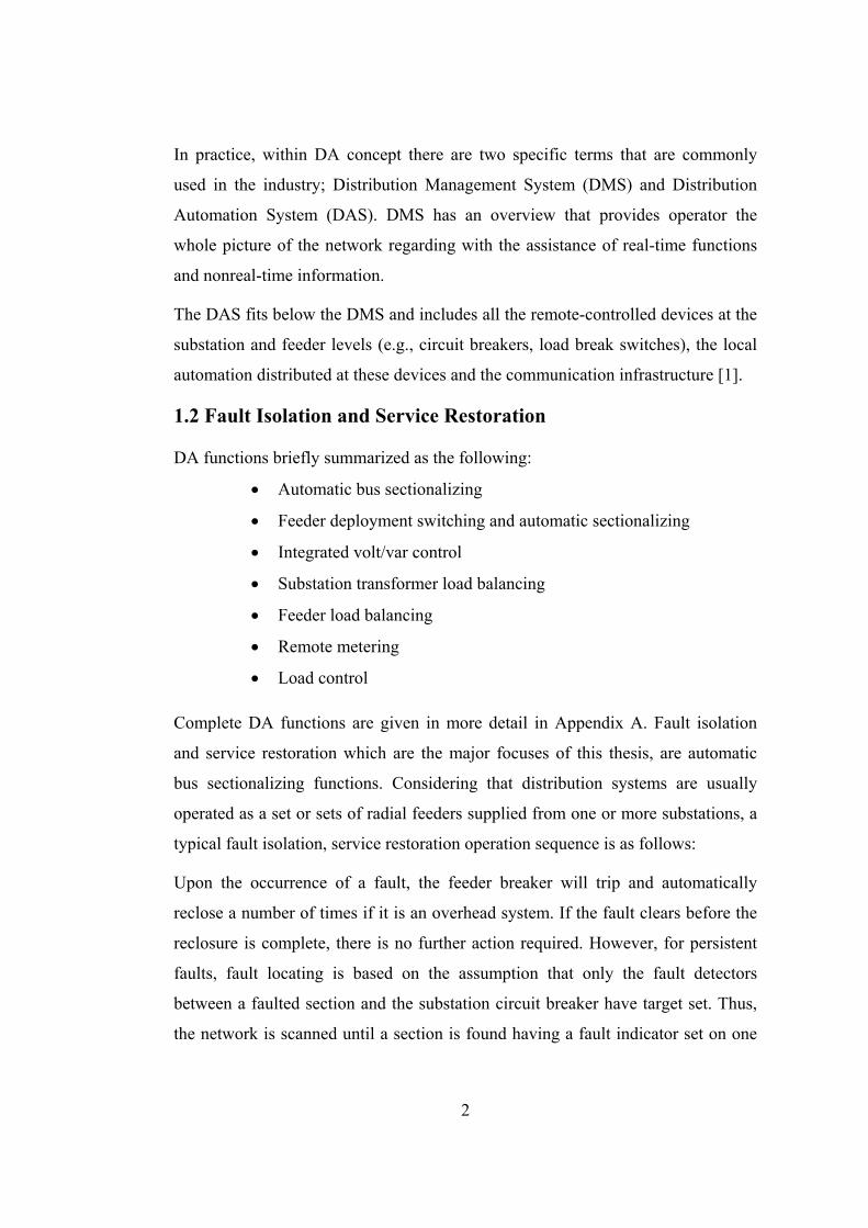
Complete DA functions are given in more detail in Appendix A. Fault isolation
and service restoration which are the major focuses of this thesis, are automatic
bus sectionalizing functions. Considering that distribution systems are usually
operated as a set or sets of radial feeders supplied from one or more substations, a
typical fault isolation, service restoration operation sequence is as follows:
Upon the occurrence of a fault, the feeder breaker will trip and automatically
reclose a number of times if it is an overhead system. If the fault clears before the
reclosure is complete, there is no further action required. However, for persistent
faults, fault locating is based on the assumption that only the fault detectors
between a faulted section and the substation circuit breaker have target set. Thus,
the network is scanned until a section is found having a fault indicator set on one

3
end, but not the other. With the faulted section specified, switches on either end of
the faulted section will be opened. This is the fault isolation part. Transferring the
remaining unfaulted and de-energized sections to another source or sources is the
service restoration function of DA. Flow chart for fault isolation and service
restoration is given in Figure 1.
Figure 1 Flow chart for fault isolation and service restoration

4
1.3 TUBITAK Distribution Automation System
Turkish Electricity Distribution Company (TEDAS) had decided to uprate the
primary distribution voltage level to 34.5 kV from 10.5 or 6 kV in big cities of
Turkey. Therefore, more loads could be served by one feeder, as a result,
reliability issue became more important. TUBITAK designed, implemented and
integrated the distribution automation system, using the technology available
complying with relevant international standards, is called TUDOSIS (TUBITAK
Distribution Automation System) for the medium voltage distribution system of
Istanbul. TUDOSIS project was carried out together with uprating distribution
voltage level. As the 34.5 kV primary distribution system would start from fresh,
then it would be easy to install automation system with its components such as
hardware (remote terminal unit, RTU), automation prepared devices (e.g.
protection relays, circuit breakers, load breaker switches) and communication
medium (at the beginning fiber optic cable).
The 34.5 kV uprated distribution feeders are loop designed but radial operated
network structure. In case of a fault, the fault current flows from the substation
through the feeder up to the fault point. Hence, the determination of fault location
is easily achieved through an RTU which is placed in the HV/MV power
substation where the feeder breaker tripped, by interrogating RTUs along the
feeder in the distribution transformers. Afterwards detection of fault location, fault
is isolated by the opening related switches. This special RTU sends information to
the control center software about fault isolation process. Control center software
should restore the system according to coming information by closing the feeder
circuit breaker and changing the normally open point location. TUDOSIS can
allow service restoration process to execute manually, semi or full automatically
by the choice of operator [3].
Unfortunately DAS could not keep up pace with the expansion of the distribution
network in Istanbul, as a result non-standardized network structures (circuit
breaker with protection relays along the feeder, mesh designed radial operated

5
network structure, closed loop system) have appeared and these drawbacks have
obstructed the development of TUDOSIS.
1.4 Contribution of the Thesis
In this thesis, a general solution of DAS that covers all variations of distribution
network infrastructures in Turkey especially in big cities is proposed. In the
literature there are two general approaches; SCADA-based and Model-based
approach. In a model-based approach, all the distribution system is modeled and
simulated in detail including distributed generation. However, it is not applicable
to passive networks and in Turkey distributed generators are usually connected to
MV buses in HV/MV substations. The proposed SCADA-based approach uses the
current assets efficiently to improve reliability. The solution proposed in this thesis
is inspired from previously implemented and tested system, TUDOSIS.
Contributions of the thesis are summarized as follows:
a) Improving fault isolation algorithm of TUDOSIS by implementing
new RTU firmware with modifying the control center software.
b) Implementing service restoration algorithm based on expert system
for mesh designed radial operated network structures.
1.5 Outline of the Thesis
In Chapter 2, a review of the previous distribution automation system, TUDOSIS,
is provided with practical drawbacks of distribution system. Chapter 3 presents
fault isolation solution for these drawbacks and discussion on essential concepts
about protection and automation. Service restoration algorithm is proposed in
Chapter 4. Finally the thesis is concluded in Chapter 5. Appendices provide
detailed discussions on the material.
6
CHAPTER 2
TUBITAK DISTRIBUTION AUTOMATION SYSTEM
2.1 Conversion to 34.5 kV Voltage Level
In the Turkish electric distribution system, the voltage is stepped down from 400
kV or 154 kV transmission level to 34.5 kV at bulk power substations, and for
rural and small-town distribution, this level is utilized without further
transformation to supply the distribution transformers whose secondaries are at
400 V. The medium voltage feeders are radial and mainly composed of overhead
lines.
Before uprating to a higher voltage level, the function of the 34.5kV feeders was to
act as subtransmission circuits to load centers where the voltage was further
stepped down to one of 6.3, 10.5 or 15 kV levels in big cities. The feeders from
these secondary substations were the open-loop type and composed of
underground cables. For Istanbul (European side), the 10.5 kV distribution
networks were manually operated conventional underground systems with 6-8
distribution transformers per feeder. Most of the existing systems are heavily
meshed with lateral branches to adjacent loops to increase the capacity from the 50
% level available from the form of a simple loop to approximately 80 % with five
lateral branches to adjacent loops. In 10.5 kV distribution system, faulted location
could be determined around 2 hours.
It is shown that 34.5 kV distribution voltage level minimizes the investments on
the high voltage (HV) system and a new primary distribution system is provided
[4]. The advantages of one primary distribution at 34.5 kV level, without involving
a second MV level are; supplying higher installed capacity than 10.5 kV
distribution level, eliminating double medium voltage (MV) transformation losses
(154 to 34.5kV then 34.5 to 10.5 kV), simple operation manner in practice and
7
implementing distribution automation covering remote fault isolation and service
restoration for reliability.
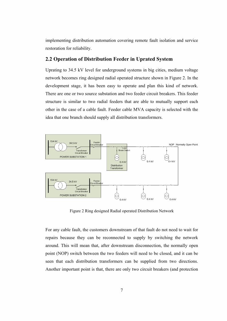
2.2 Operation of Distribution Feeder in Uprated System
Uprating to 34.5 kV level for underground systems in big cities, medium voltage
network becomes ring designed radial operated structure shown in Figure 2. In the
development stage, it has been easy to operate and plan this kind of network.
There are one or two source substation and two feeder circuit breakers. This feeder
structure is similar to two radial feeders that are able to mutually support each
other in the case of a cable fault. Feeder cable MVA capacity is selected with the
idea that one branch should supply all distribution transformers.
Figure 2 Ring designed Radial operated Distribution Network
For any cable fault, the customers downstream of that fault do not need to wait for
repairs because they can be reconnected to supply by switching the network
around. This will mean that, after downstream disconnection, the normally open
point (NOP) switch between the two feeders will need to be closed, and it can be
seen that each distribution transformers can be supplied from two directions.
Another important point is that, there are only two circuit breakers (and protection
8
relay groups) at the start of the feeders and load break switches are utilized to
isolate the sections of faulted cable between the distribution transformers.
Protection system will work such as, in the case of fault related protection relay (at
the end of the feeder) senses the fault and circuit breaker should be tripped and
fault will be cleared.
2.3 Functions of TUDOSIS
Whit the utilization of 34.5 kV level for supplying distribution transformers, the
number of distribution transformers served was more than tripled (10.5 kV voltage
level), the exposure length and therefore the number faults would also increase in
the same proportion. These feeders could no longer be operated manually.
Therefore, TUDOSIS was designed and implemented for the Istanbul (European
side) distribution system and it had been operated by Bogazici Electric
Distribution Company (BEDAS) since 1996.
The functions of TUDOSIS can be summarized as follows:
• Data Acquisition: Status of switchgears (i.e. circuit breakers, load
break switches and fuses), protection relays’ information, loads of
the transformers and feeder currents and bus voltages etc.
• Remote Control: Controlling of switches.
• Fault Isolation
• Service Restoration
2.3.1 Fault Isolation
The line or the bus faults along the feeder are sensed by the protection relay (earth
fault or overcurrent relay) and this information is acquired by special RTU called
line end terminal unit (LETU). The feeder circuit breaker opens (trips) and its state
is reported to control center software indicating the reason of tripping through
LETU (Figure 3).
Fault isolation process has both centralized and distributed control approach.
LETU performs fault location detection and isolation as a multi-agent device [5].

9
In normal communication condition (no communication failure between LETU
and all the RTUs in distribution transformers along the feeder), LETU determines
fault location by interrogating fault passage indicators (FPI) one by one until the
end of the feeder. The faulted region is defined as the section just before the first
no fault current indication. The switches that correspond to the last fault current
indication and the one after this indicator are opened to isolate the section. Fault
isolation is shown in Figure 4.
Figure 3 Feeder Line Fault and Protection System
Feeder C.B.
154/34.5 kV
154/34.5 kV
Substation
Feeder C.B.
34.5/0.4 kV
N.O.P.
Cable Fault
Protection relay senses fault and C.B. trips
10
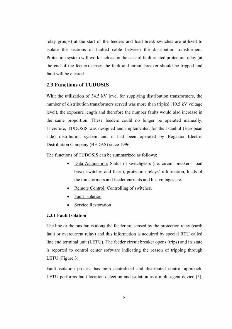
Figure 4 Fault Isolation System
The distributed approach of fault isolation is propounded by the need to minimize
the interrupted duration and increase the efficiency. If there is a communication
failure along the feeder, the LETU queries RTUs which it can reach and sends a
message that includes fault passage indicator information of the reached region
and leaves the isolation to the control center software. When control center
software receives such a message, it isolates the minimal region indicated by the
message without doing any analysis. In that case, centralized fault isolation system
takes the control.
2.3.2 Service Restoration
After the isolation of the faulted section, service restoration system is a centralized
approach that reenergizes downstream of the faulted section, and done by the
control center software. The de-energized region between tripped feeder circuit
breaker that has been opened by the feeder relays and the faulted location of the
Feeder C.B.
154/34.5 kV
154/34.5 kV
Substation
Feeder C.B.
34.5/0.4 kV
N.O.P.
Open load breakers
and isolate fault

11
feeder will be supplied by closing the feeder circuit breaker. During restoration in
order to eliminate in-rush currents, distribution transformers should be energized
step by step. Since the feeders are operated as an open loop network, previously
normally open switch is closed and rest of the de-energized portion of the feeder
has been restored. This process is shown in Figure 5.
Figure 5 Service Restoration System
2.4 Components of TUDOSIS
The basic architecture of TUDOSIS comprises four main components: the device
to control and acquire data from power system (Distribution transformer terminal),
a communication system, distribution automation gateways and man-to-machine
interface (MMI) software (i.e. control center software).
154/34.5 kV
Substation
154/34.5 kV
Substation
Feeder C.B.
34.5/0.4 kV
Closed feeder circuit breaker
Closed previous
N.O.P. load break sw
12
2.4.1 Remote Terminal Units of TUDOSIS
There are four types of RTUs; Control Station Terminal (CST), Substation
Terminal (SST), Line End Terminal Unit (LETU) and Distribution Transformer
Terminal (DTT).
• CST: CST is the communication interface between SST and control
center.
• SST: ST is the communication interface between CST and LETU.
They are gateways to route messages coming from control center to
related RTU according to their communication roadmaps.
• LETU: LETU acquires information about circuit breakers on/off
states, protection relays, feeder currents and bus voltages in the
power substations. Also it is the communication link between the
SST and DTT. It performs fault location detection and isolation
even though the control center is not online in its responsibility
region.
• DTT: DTT gathers all information in the distribution transformers.
Network of TUDOSIS is implemented in parallel architecture with distribution
system. It is in hierarchical structure to easily adapt future expansion of the
distribution system (Figure 6).
2.4.2 Communication System of TUDOSIS
TUDOSIS uses DNP for RTU-RTU and RTU-control center workstation
communication. The DNP is based on the IEC 870-5 protocol which uses EPA
(Enhanced Performance Architecture) as defined by OSI (Open System
Interconnection) protocol [6].
TUDOSIS communication infrastructure is generally fiber optic cable. The reason
is that, fiber optic cables were laid along with 34.5 kV power cables, and therefore,
there would be no extra cost.

13
Figure 6 TUDOSIS Network Architecture
2.4.3 Control Center Software of TUDOSIS
UNIX-based control center software that runs on SUN workstations and Solaris 7
operating system was developed for TUDOSIS. In the design and implementation
of the system, special care had been given to the usability and openness of the
system. MMI was implemented in C++ which has an object oriented programming
paradigm to cope with the complexity of the system and to enable easy
maintenance [7].
TUDOSIS control center software has the following features:
• displaying one-line diagrams of the distribution system, with real-
time switch states indicated (Figure 7),
• sending operator commands,
• isolating faults on feeders (centralized approach),
• restoring feeder de-energized sections,
• keeping historic logs of events and real-time data,
• handling alarms.

14
All of these components were implemented and integrated to the Istanbul
(European Side) MV (34.5 kV) distribution system and TUSOSIS has been
operated from 1996 till today.
Figure 7 A Snapshot of Control Center Software of TUDOSIS
2.5 Practical Drawbacks in Integration of TUDOSIS
As mentioned before TUDOSIS was designed for ring designed, radial operated
(open loop) MV cable distribution system. In this network structure, circuit
breakers are located only at the upper ends of the feeder and load break switches
are installed in distribution transformers (transformer switching is done by a load
break switch in series with fuse). By itself, feeder circuit breaker cannot trip when
fault occurs. However, suitable protection relays are arranged to detect a fault
condition, initiate the automatic tripping of the breaker and LETU performs fault
isolation.
15
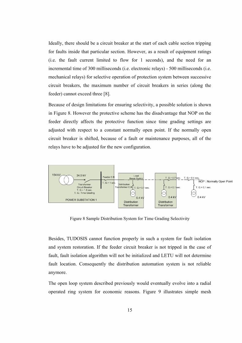
Ideally, there should be a circuit breaker at the start of each cable section tripping
for faults inside that particular section. However, as a result of equipment ratings
(i.e. the fault current limited to flow for 1 seconds), and the need for an
incremental time of 300 milliseconds (i.e. electronic relays) - 500 milliseconds (i.e.
mechanical relays) for selective operation of protection system between successive
circuit breakers, the maximum number of circuit breakers in series (along the
feeder) cannot exceed three [8].
Because of design limitations for ensuring selectivity, a possible solution is shown
in Figure 8. However the protective scheme has the disadvantage that NOP on the
feeder directly affects the protective function since time grading settings are
adjusted with respect to a constant normally open point. If the normally open
circuit breaker is shifted, because of a fault or maintenance purposes, all of the
relays have to be adjusted for the new configuration.
Figure 8 Sample Distribution System for Time Grading Selectivity
Besides, TUDOSIS cannot function properly in such a system for fault isolation
and system restoration. If the feeder circuit breaker is not tripped in the case of
fault, fault isolation algorithm will not be initialized and LETU will not determine
fault location. Consequently the distribution automation system is not reliable
anymore.
The open loop system described previously would eventually evolve into a radial
operated ring system for economic reasons. Figure 9 illustrates simple mesh

16
system with three lateral branches. TUDOSIS again cannot fulfill its functions
with this type of network. LETU cannot be installed in the node distribution
transformer because of both hardware and embedded software limitations. Service
restoration algorithm was designed for two supply substation architecture which is
not applicable in this case that has three supply points.
Closed ring distribution network is not feasible architecture for feeders which are
supplied from two substations. Paralleling two different 154/34.5 kV substation
transformer causes circulating currents and also short circuit currents roughly will
be doubled. This situation will change whole protection system of distribution and
transmission system.
Figure 9 Sample Mesh Network System

17
CHAPTER 3
FAULT ISOLATION ALGORITHM
3.1 Literature Survey: Fault Isolation Algorithms
Numerous approaches have been proposed to solve the problem with fault
detection and isolation in electrical power systems, and commonly used ones are
briefly discussed below.
These are classified into two categories: SCADA-based and Model-based Fault
Detection and Isolation.
3.1.1 SCADA-based Fault Detection and Isolation
In this approach, fault detection and isolation is performed using the alarms from
the system. Protection system leads DA for fault detection and selectivity is
accomplished by coordinated operation of protection relays. In large systems the
number of alarms resulting from a fault event can be quite substantial, which
increases the challenge of fault isolation for the system operator. At this point DA
is usually implemented using either a centralized approach or a distributed
approach.
An accepted example of distributed solution for fault isolation and service
restoration is the IntelliTEAM II Automatic Restoration System which was
introduced by S&C Electric Company in 2003 [9]. IntelliTEAM II can automate
parts of a circuit in need of attention or an entire distribution system consisting of
open-loop feeders with multiple normally open points to other feeders. “Team”
and “coach” metaphors help to describe IntelliTEAM II operation. Each team is
defined as a line segment bounded by two to eight automated switches and each
team has a software coach.
18
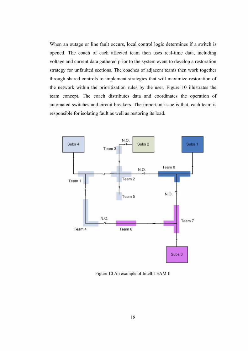
When an outage or line fault occurs, local control logic determines if a switch is
opened. The coach of each affected team then uses real-time data, including
voltage and current data gathered prior to the system event to develop a restoration
strategy for unfaulted sections. The coaches of adjacent teams then work together
through shared controls to implement strategies that will maximize restoration of
the network within the prioritization rules by the user. Figure 10 illustrates the
team concept. The coach distributes data and coordinates the operation of
automated switches and circuit breakers. The important issue is that, each team is
responsible for isolating fault as well as restoring its load.
Figure 10 An example of IntelliTEAM II
19
Another implemented example using distributed approach is TUDOSIS which was
mentioned in Chapter 2. The advantage of this approach is that it can properly
isolate fault and restore de-energized region without requiring the knowledge of
system topology and other network parameters.
In case of fault, when a breaker or its associated relays fail to operate, the fault is
removed by backup protection. For large systems, in such cases, it is difficult for
the dispatchers to estimate the fault location. Moreover, multiple faults may take
place, with many breakers being tripped within a short time. In these
circumstances, centralized solutions have been proposed to assist the system
operator providing accurate fault location. Artificial neural networks (ANN) have
been successfully applied to fault detection and isolation problems. For instance in
[10], the method explores the fact that the identification of a faulted component
requires only information from alarms originating from faulted region. A local
strategy is followed to tackle the problem of dimension. Decision rules are
presented in order to achieve accurate final diagnoses from the analysis of the
ANN classifications. Alternative to ANN, expert systems are able to produce
successful results for fault diagnosis [11]. In this thesis rule-based expert systems
are discussed in Chapter 4 for service restoration. These solutions are fault tolerant
and provide system wide approach.
3.1.2 Model-based Fault Detection and Isolation
In model-based fault detection the knowledge of the physical system is exploited,
using well established relationships from power engineering to describe the
behavior of the system. Observing contradictions, between the predicted behavior
from the model and the behavior observed, conclude that the normal behavior of
the system is violated, and hence that a fault has occurred. This general idea can be
implemented in a number of ways, and only a couple of them is mentioned here.
3.1.2.1 Look-up Table Approach
This approach comprises protection scheme for distribution network including
distributed generation (DG). The protection scheme is based on a complete short

20
circuit analysis for every type of fault applied anywhere in the system, where the
contributions to the faults from different supplies are stored in a database.
Following a fault, the pattern of the realized flow from the sources is compared to
the ones simulated to detect the fault and isolate the fault location. As the short
circuit analysis is only valid for a specific configuration of network, generation
and load, accurate detection requires that the analysis is updated after change in
the distribution system [12]. The basis for this solution is that the contribution to
the fault current from different supplies, constitute a unique fingerprint for type
and location of the fault. A drawback with this method is that the protection
scheme needs time to reconfigure following a significant change for next system
state. During this period there is a reliability problem.
3.1.2.2 Dynamic Model Evaluation Approach
In [13], an on-line fault detection scheme is proposed, where faults are treated as
unknown inputs to the power system model. Through the model, measurements
contain information about fault type and related recordings, and in case a fault
occurs, the fault detection and isolation is performed by an observer, where the
unknown input is estimated. Once the system is modeled, the dynamics that
described the faults are decoupled from the rest of the system, after which the
unfaulted part of the system is used to design an observer that estimates the
remaining part of the system, including the unknown faults.
3.2 Proposed Method: SCADA-Based Distributed Approach
In this thesis SCADA-based distributed approach is proposed for fault detection
and isolation method which has originated from TUDOSIS fault isolation
algorithm. Drawbacks concerning integration of TUDOSIS are discussed in
Chapter 2. To answer these problems, a new fault isolation algorithm has been
developed with novel remote terminal unit structures. The distribution system is
represented in an object oriented programming (OOP) language, C#. Afterwards
protection system and DA components (RTU) along with fault detection and
isolation algorithm are implemented in this representation.
21
3.2.1 Representation of Distribution System
The basic components used in the distribution system can be classified as
switching, conduction and protective components in representative point of view.
Transformers and other measurement devices are out of scope elements for this
study. The following table gives generally the specifications of these elements:
Table 1 Distribution System Elements
Type Explanation
Circuit Breaker Interrupting fault current Switching (on/off) under load
Load Break Switch Only switching (on/off) under load Bus Conduction structure in substations Cable Conduction structure between substations
Before going a step further in distribution system modeling, OOP design and
programming terminology are expressed.
3.2.1.1 OOP Design and Programming Concepts
• Objects and Methods Software executes when a data structure (of varying levels of
complexity) is acted upon by one or more processes according to
procedure defined by static algorithms or a group of dynamic
commands. Therefore, OOP language must establish a mechanism
to accomplish these functionalities [14]. The data elements and the
available processes on those elements are encapsulated in a single
programming element called “object”. An object is the entity which
corresponds to a real world component such as a machine, a file, an
integer or an electrical signal. Software realization of objects
consists of private (no access right is given to other objects) or
public data structures that are also called attributes and processes
manipulating those structures. These processes are called
“methods”. The only way of manipulating the object, is calling the

22
object methods. In other words methods are interface of an object to
the outer object space. Figure 11 gives an example of “switch”
object which has a type (circuit breaker, load breaker or disconnect
switch), location, rating, connection points and relays and also it
can be opened and closed.
Figure 11 A Sample Object: Switch
• Classes and Class Inheritance One can group objects, having same characteristics and similar
operations, into groups that are called classes. The data and
interface design (attributes and methods) is defined in the class
implementation.
Classes having similar characteristics can be grouped under
hierarchical graph. The hierarchy is constructed according to the
coverage of generalized characteristics. Most generalized classes
are at the top (parent) and traversing to the bottom, more specialized
classes (children) are passed through. The children in the hierarchy
inherit general characteristics of its parents. This mechanism is
transitive; C is child of B and B is child of A means the
characteristics of A is passed to C. This new-class generation from
generic groups to specific ones (i.e. book to dictionary, animal to
mammal) is accomplished by a mechanism, is called “inheritance”.
23
• Polymorphism Polymorphism is the ability to change into morphologic forms and
in OOP, is the term to denote the ability to have different types of
objects and structures to initiate a known pattern of interrelations
through inheritance. This feature of OOP makes modular and
extensible programming very easy and avoids code duplication. To
achieve polymorphism, inheritance mechanism is used in a special
form which enables an abstract class (A class which has no
instances itself but uses its descending class instances as its own) to
behave like its multiple forms of inheriting classes. This abstract
class can change its behavior at run time by simple constructors
defined in the program code [14].
3.2.1.2 Simulation Environment of Distribution System in C#
A simulation program is written which represents the distribution and its
automation system for clearer understanding of the fault isolation algorithm. Using
the OOP benefits, first an “EDeviceBase” class is created. EDeviceBase is the
parent of the all electrical equipments in the simulation program, which inherits
from UserControl class in C# library. EDeviceBase class properties and methods
are given in Figure 12. “Bus”, “Cable”, “CircuitBreaker” and “LoadBreaker” are
children classes of EDeviceBase class.
Bus object is located in the HV/MV substations and distribution transformer
stations. It ties two or more switching device (circuit breaker or load break switch)
to each other. Cable object connects only two switching device to each other or
one bus to a switching device.

24
Figure 12 EDeviceBase Class Properties (and Fields) and Methods (and Events)
Circuit breaker object is a switching device which is opened (or tripped) in the
case of a fault. However, load breaker object is a switching device which cannot
be triggered by the discharge method (a method which is triggered by the faultset
method). The class diagram of electric equipments is shown in Figure 13.

25
Figure 13 Class Diagram of Electric Equipments
In the same manner, RTU is the parent object of the other RTU structures; LETU,
LITU, DTT and NDTT. RTU is connected to switching devices (circuit breakers
or load break switches) in the substation or distribution transformer stations. When
switching devices status is changed (tripping of circuit breaker), attached RTU will
perceive the alteration and invoke the related method. Class diagram of RTU and
its children is given in Figure 14.

26
Figure 14 Class Diagram of RTU
In C# programming language environment, using these proposed objects a
distribution network can be designed and implemented. It is an easy and flexible
coding approach for the developer. When the project file is opened, both C#
components and developed components can be dragged and dropped in to
framework of the program (Figure 15). After constructing substructure of the
distribution system, the program should be compiled and run to realize and
simulate the fault isolation algorithm.

27
Figure 15 Graphical User Interface of the Simulation Program
3.2.2 Fault Isolation Algorithm
Starting point of this thesis is to overcome unplanned development of the
distribution system. Effectiveness of the selectivity must be questioned and
improved for installed circuit breakers with protection relays. Some of the relays
have been made inoperative to satisfy selectivity limitations. For example, twenty
distribution transformers in an open loop feeder, supplied by two power
substations, two protection relays are set for one feeder and two for the other
feeder. After coordination of protection scheme, novel RTU structures are
proposed; one of them is for distribution transformer (LITU) with relays and
another is for node distribution transformers (NDTT).
Composed objects
Existing objects
Implemented
Distribution System
28
LETU has a DTT list which comprises DTTs from itself to next RTU with relays.
This field of the LETU intends to decrease interrogation region. If associated
circuit breaker trips, it will question all the DTTs in the list, and will find the fault
location by analyzing last faulted passage indicator set value. When a breaker or is
associated circuit breaker fails to operate, LETU will consider the faulted situation
and assign the task to next RTU with relays (probably LITU).
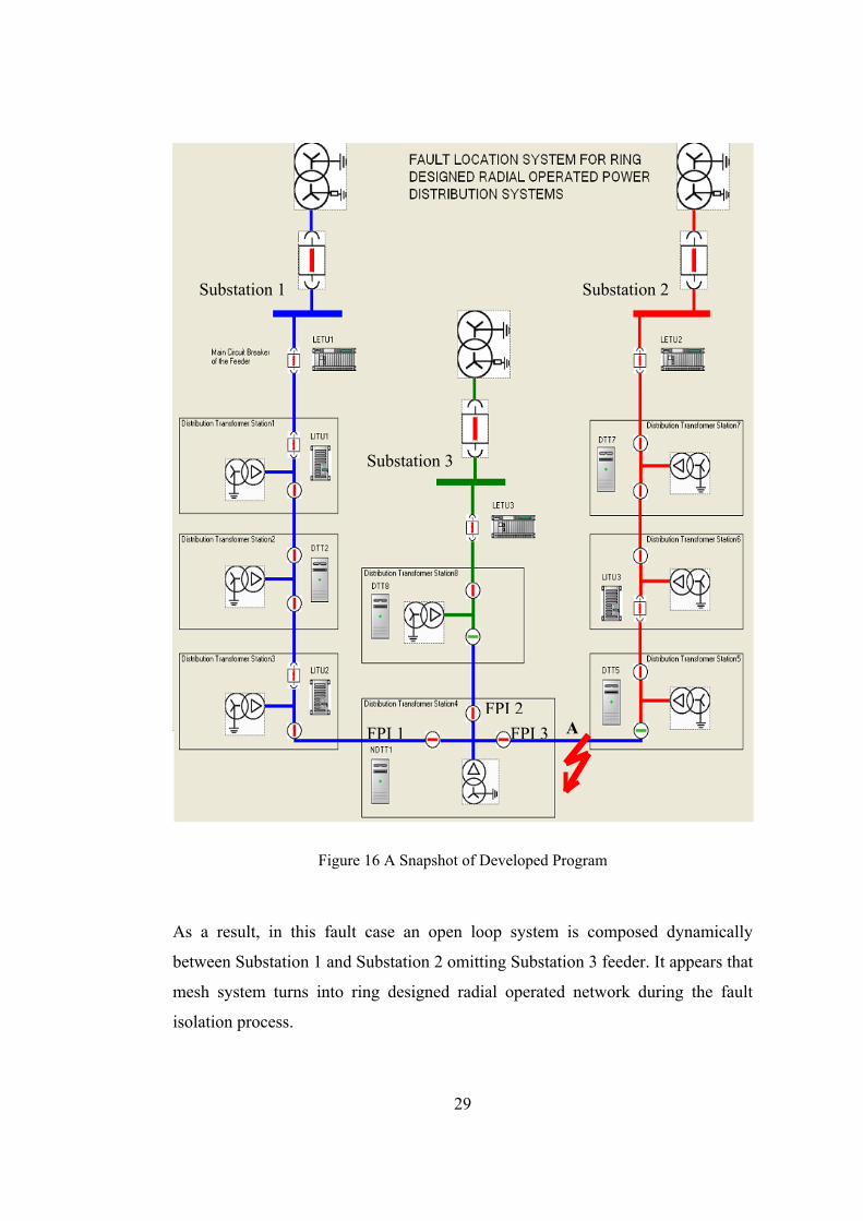
For mesh network system it is difficult to track and keep the fault passage
indicators’ information. NDTT partakes in fault detection algorithm by having
branch lists (incoming or outgoing feeders from node distribution transformer).
Every branch list covers DTTs data and next RTU with relay information. In
Figure 16, NDTT1 (NDTT object) has the information of next LITUs (LITU2 and
LITU3) and also DTTs (DTT5 and DTT8) for every branch.
For instance, when a fault occurs at point A, fault current flows from Substation 1
to fault location. Upstream circuit breaker will trip and LITU2 will interrogate
NDTT1 fault passage indicators (in this case FPI 2 and FPI 3). FPI 3 is set to 1,
subsequently LITU2 will append feeder by adding DTT5 to its DTT list and
LITU3 to its newt switching RTU with relay.
29
Figure 16 A Snapshot of Developed Program
As a result, in this fault case an open loop system is composed dynamically
between Substation 1 and Substation 2 omitting Substation 3 feeder. It appears that
mesh system turns into ring designed radial operated network during the fault
isolation process.
Substation 1 Substation 2
Substation 3
AFPI 1FPI 2
FPI 3

30
LITU object is extended version of the LETU. LETU has only one DTT list but
LITU has two DTT lists in case of changing current direction. DTT list selection is
determined by recognizing the normally open point switch. Same understanding is
exploited for NDTT case. Consequently, installed circuit breakers with relays in
the feeder and also mesh distribution networks this novel SCADA-based approach
is a solution for fault detection and isolation.
3.3 Closed Loop Distribution System Protection and DA System
In ring designed and ring operated (closed loop) distribution network’s protection
scheme is completely different from the open loop system. In an open loop system
(described in Chapter 2) over-current and earth fault current relays are used and
selectivity limitation determines the number of the relay in the feeder. In the case
of a fault or a maintenance work, whenever normally open point of the feeder
changes, selectivity is altered and reconfiguration is needed for new feeder
structure. It can be done with remote programming of the relays.
However, closed loop system protection scheme is distinguished from open loop
system because of fault current flow. For closed loop cable distribution systems
there are two different solutions. One of them is directional over-current relays and
the other is line differential relays.
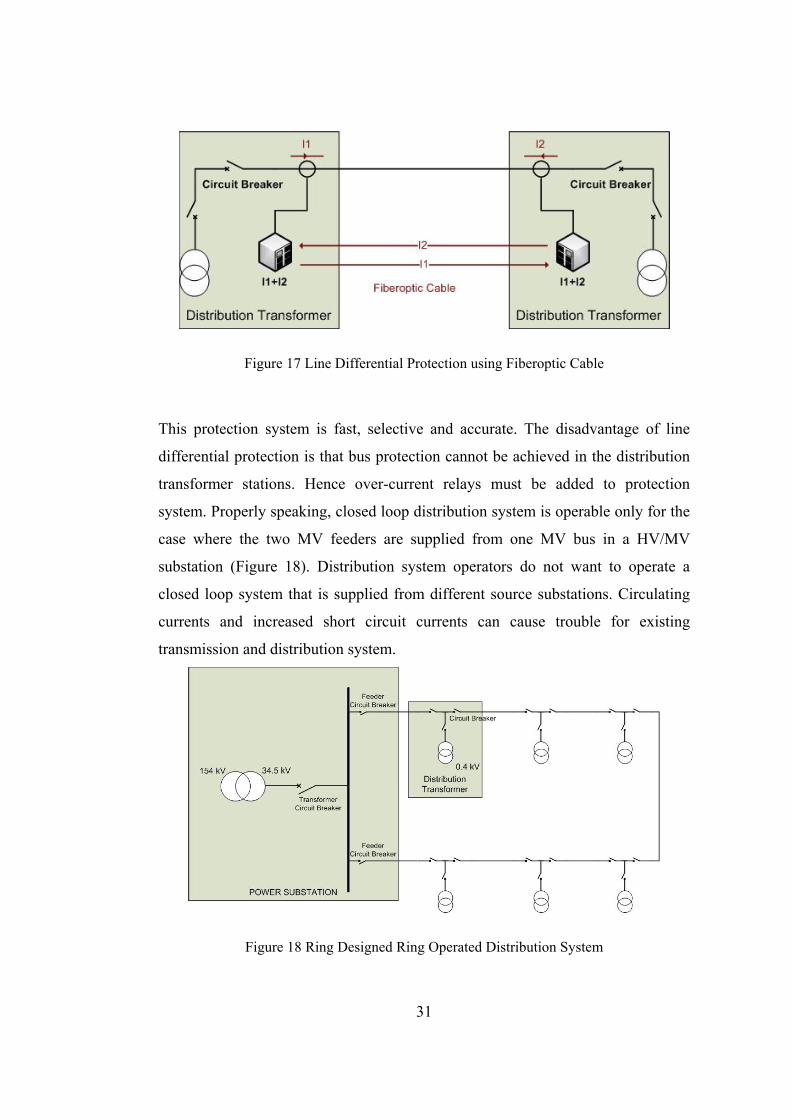
3.3.1 Line Differential Protection
Line differential protection is a unit protection type (Figure 17). In normal
condition (there is no fault between two distribution transformer stations) the sum
of incoming and outgoing currents (I1+I2) equals to zero. When a fault occurs at
the line, I1+I2 will not be zero and relays will generate trip signal reciprocally.
Afterwards circuit breakers will be opened and fault isolation eventuates.
Therefore a fault isolation algorithm and service restoration algorithm in DA is
inessential.
31
Figure 17 Line Differential Protection using Fiberoptic Cable
This protection system is fast, selective and accurate. The disadvantage of line
differential protection is that bus protection cannot be achieved in the distribution
transformer stations. Hence over-current relays must be added to protection
system. Properly speaking, closed loop distribution system is operable only for the
case where the two MV feeders are supplied from one MV bus in a HV/MV
substation (Figure 18). Distribution system operators do not want to operate a
closed loop system that is supplied from different source substations. Circulating
currents and increased short circuit currents can cause trouble for existing
transmission and distribution system.
Figure 18 Ring Designed Ring Operated Distribution System

32
3.3.2 Directional Over-Current Protection
Directional over-current relays indicate whether the fault is in the upstream or the
downstream direction from where they are located and trip the associated circuit
breaker. For this purpose a directional protection relay needs a source of both
current and voltage. The current source can be current transformer which is
toroidal type or plastic moulded case. The voltage source might be a wound
voltage transformer on a new cell or cubicle. Once more ensuring selectivity
causes design limitation in protection system. Fault isolation algorithm considers
the circuit breaker tripping and directional fault passage indicators information to
determine exact fault location.
Ring designed, ring operated distribution system, for both approaches, requires
additional equipments (voltage transformer, directional over-current relays, line
differential protection relays etc.) that increase the operating cost of the system.
Considering fault location statistics (faults at MV or LV), distribution system
operator should make cost-benefit analysis. If number of LV faults is much more
than MV faults, line differential protection system will be a luxury and therefore
useless.
33
CHAPTER 4
SERVICE RESTORATION
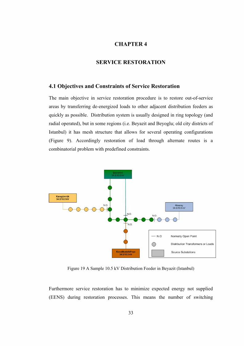
4.1 Objectives and Constraints of Service Restoration
The main objective in service restoration procedure is to restore out-of-service
areas by transferring de-energized loads to other adjacent distribution feeders as
quickly as possible. Distribution system is usually designed in ring topology (and
radial operated), but in some regions (i.e. Beyazit and Beyoglu; old city districts of
Istanbul) it has mesh structure that allows for several operating configurations
(Figure 9). Accordingly restoration of load through alternate routes is a
combinatorial problem with predefined constraints.
Figure 19 A Sample 10.5 kV Distribution Feeder in Beyazit (Istanbul)
Furthermore service restoration has to minimize expected energy not supplied
(EENS) during restoration processes. This means the number of switching
34
operations (open/close switches) is minimized, through switching sequence is
considered. Another important issue is supplying energy to the largest number of
loads as possible. After restoration to final configuration, total power losses have
to be reduced.
All these objectives cannot be provided simultaneously, thus service restoration
will assist the system operator by the control center software (Automatic service
restoration is not recommended in practical manner).
Final configuration must not violate operational constraints. The constraints are
summarized as following;
• During and after restoration process, distribution system must retain
radial topology.
• Source substation and line loadings must not exceed the capacity
limit.
• Voltages at the load buses must stay between the limits (0.95< Vbus
<1.05)
4.2 Methodology
An effective service restoration strategy for distribution systems plays a key role in
improving system reliability. As a result there has been considerable research
efforts focused on restoration problem. The problem has been addressed with
methods such as integer programming, ANN, genetic algorithm, rule-based expert
systems and hybrid systems.
4.2.1 Integer (Mathematical) Programming
Integer programming as given in [16], proposes a non-combinatorial, systematic
and procedural algorithm. From the view point of this method, the loads in the
“isolated island” must be energized by transferring them to “support feeders”. In
this case, there are radial feeders along with the faulted feeder and a group of de-
energized loads with connections to these feeders. Constraints of approach are
line/transformer capacity and voltage drop at the end of the line.

35
As a first step, solution algorithm determines the “main support feeder”. This
feeder is chosen by connecting isolated island to every adjacent feeder and
deciding minimum constraint violation among these feeders. If there is no
constraint violation, service restoration is completed. Otherwise, algorithm moves
on to the first support stage. Tie switches that can be used to transfer loads from
feeder that has caused constraint violation to the adjacent feeders are identified,
then a tie switch and the associated feeder are chosen to transfer loads one-by-one.
Again if there is violation constraint, second stage support feeders are determined
by tolerating some violations in the first support feeder. Now the first stage
support feeder is treated as a main support feeder with constraint violation.
After second stage support, if there are still violations, load curtailment is
performed. There may be some possibilities in restoring the curtailed loads by load
transfer among former violation feeders (main, first and second support feeders).
Therefore tolerating some violations, loads are tried to be supplied from the former
feeders.
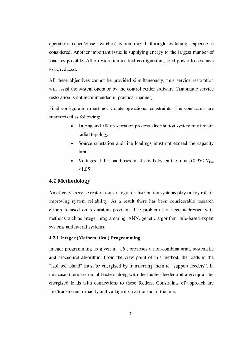
4.2.2 Artificial Neural Network (ANN)
In [17], ANN approach is developed to determine the service restoration plan for a
distribution system within the service area of Taiwan Power Company. A typical
underground distribution network is shown in Figure 20. It is observed that feeder
coming from S/S 2 can supply power to feeder S/S 1 in the case of fault. In
addition, three laterals (LAT1-3) are connected with supporting laterals. Also,
there may exist some laterals (LAT 4) without supporting laterals.
36
Figure 20 One-line diagram of the studied system
For example, after the fault at point A on Feeder 1 has been isolated, LAT1-4 is
de-energized. To restore service to these laterals, Feeder 2 can be used by closing
the SW 5. If the supporting feeder does not have enough spare capacity to LAT1-
4, ANN algorithm must select some additional supporting laterals. One of the
requirements of this method is only the switches which are in the near vicinity to
out-of-service area may be operated. According to this requirement,
reconfiguration of supporting laterals is not considered.
The ANN employed in this approach is multilayer feed forward neural network. In
general, an ANN is made up of neurons connected together via links. ANN solves
a complicated problem very efficiently because the knowledge about the problem
is distributed in the neurons and connection weights of links between neurons and
information are processed in parallel. ANN inputs are the capacity of the
supporting laterals and supporting feeder and the outputs are these supporting
laterals’ (or feeder) switch positions.

37
4.2.3 Evolutionary Algorithm (EA)
The common underlying idea behind evolutionary algorithm techniques is the
same: given a population of individuals, the environmental pressure causes natural
selection (survival of fittest) and this causes a rise in the fitness of the population.
Given a quality function to be maximized, a set of candidate solutions, i.e.,
elements of the function’s domain, is randomly created and the quality function is
applied as an abstract fitness measure – the higher the better. Based on this fitness,
some of the better candidates are chosen to seed the next generation by applying
recombination and/or mutation to them. Recombination is an operator applied to
two or more selected (from current generation) candidates, and results in one or
more new candidates. Mutation is applied to one candidate and results in one new
candidate. Executing recombination and mutation leads to a set of new candidates
that compete – based on their fitness – with the old ones for a place in the next
generation [18].
One of the implementations of EA to service restoration problem is proposed in
[19]. In this approach first of all distribution network is represented as a graph. A
graph consists of nodes, which represent loads (distribution transformer) and edges
which are branches (lines) between two distribution transformers (Figure 21).
Edges are unidirectional that means current flow direction may change according
to feeder configuration. Every feeder is represented as a data structure called tree,
thus graph is a forest of these trees. For example, in Figure 21 the nodes starting
with 1 (root of tree) and through the nodes 4, 5, 9, 13, 8, 12 compose a tree
(feeder) with connection edges.
After representation of distribution network, EA needs operators (recombination or
mutation) to generate new candidates. Mentioned approach has two operators that
changes two trees and makes up a new forest. Both operators can transfer a
subtree from a tree to another tree. Only difference is operator1 keeps root of the
subtree unchanged, but operator2 changes the root and also configuration of the
subtree.

38
Figure 21 Mesh Distribution System with three feeders
Loads (or nodes) are defined as a constant current model; the load flow can be
easily calculated for currents from terminal loads to substation and then from
substation to terminal nodes for voltages. Constraints can be summarized as
follows; radial network structure, line capacity, source substation capacity and
voltage drop.
At this point, proposed method has distribution system structure, load flow
algorithm and EA operators. After fault isolation, out-of-service area can be
considered as a subtree. Using operators (1 or 2), de-energized area is connected to
another feeder (tree). This first configuration (individual) can violate one or more
constraints, so it is necessary to find a better configuration. Starting from this
individual, stochastically EA can produce other configurations by applying
operators. For this process the parameters are population size (how many
individuals must remain for the next generation) and maximum generation number
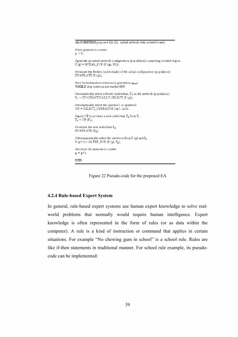
(how many individual must be generated). Pseudo-code for the proposed EA is
given in Figure 22. Finally after running of the proposed algorithm or other EA
approaches offline, system operator has a group of restoration procedure according
to operational constraints.
39
Figure 22 Pseudo-code for the proposed EA
4.2.4 Rule-based Expert System
In general, rule-based expert systems use human expert knowledge to solve real-
world problems that normally would require human intelligence. Expert
knowledge is often represented in the form of rules (or as data within the
computer). A rule is a kind of instruction or command that applies in certain
situations. For example “No chewing gum in school” is a school rule. Rules are
like if-then statements in traditional manner. For school rule example, its pseudo-
code can be implemented:

40
IF
I am in school.
AND
I am a chewing gum.
THEN
Spit out the gum
END
Using this very general definition, it might be concluded that all the knowledge
available about the world can be encoded as rules. For a problem, if facts
(environment, i.e. distribution network) and rules are encoded, a rule-based system
will use these rules to derive conclusions. According to this structure, important
advantages are:
• ability to capture and preserve human experience,
• minimize human expertise needed at a number of locations at the
same time,
• solutions can be developed faster. Rule-expert system has a general
structure shown in Figure 23. Programmer or developer can use the
interface to encode the real life problem. Knowledge base stores
rules and facts that are entered by the user concerning the problem.
Then inference engine controls the whole process of applying the
rules to the facts to obtain the outputs of the system.

41
Figure 23 General structure of rule-based Expert System
After brief introduction to expert systems, can rule-based expert system be a
remedy to service restoration problem? Several investigations have been carried
out in the past [20]-[21] exploiting expert systems. The algorithm acquired from
literature and side experiences are discussed in 4.2.6.
4.2.5 Hybrid Systems (Expert System with Genetic Algorithm)
Hybrid systems combine expert systems with genetic algorithm (or other
approaches) to solve service restoration problem. Service restoration is a
combinatorial and constrained optimization problem. Some approaches that have
been mentioned before deal with restoring the out-of-service area as soon as
possible. But in [22], the starting point is the total power source capacity may not
be enough to restore the whole de-energized region and supply margins of
supporting power sources have to be increased. In such a situation, expert system
determines configuration of the network to increase supply limits. After providing
sufficient supply capacity, genetic algorithm determines switch operations by
42
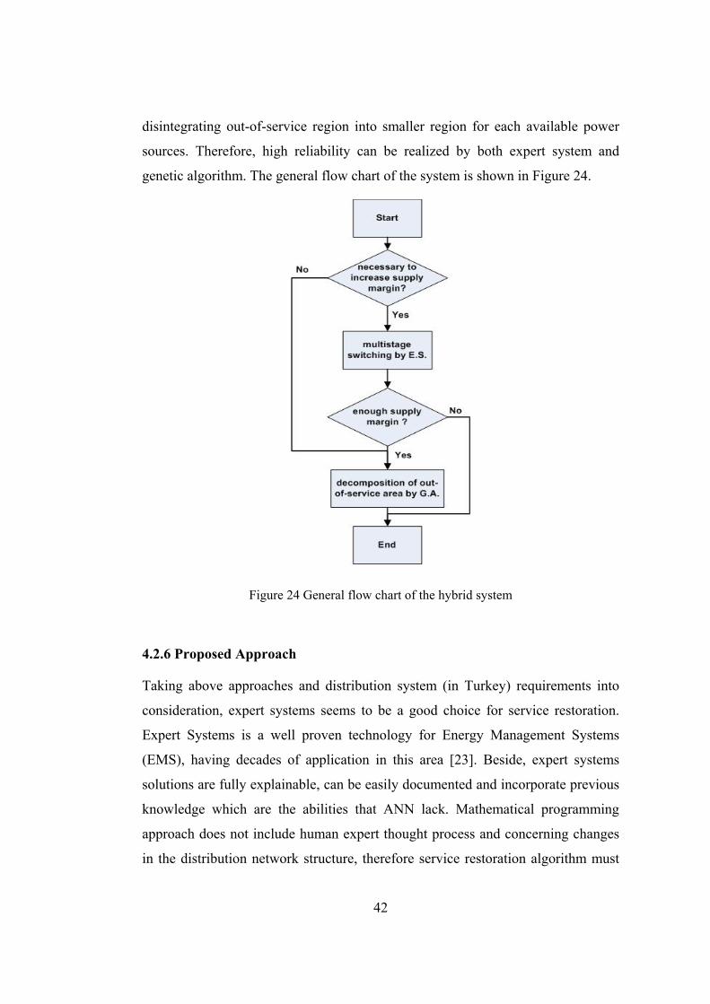
disintegrating out-of-service region into smaller region for each available power
sources. Therefore, high reliability can be realized by both expert system and
genetic algorithm. The general flow chart of the system is shown in Figure 24.
Figure 24 General flow chart of the hybrid system
4.2.6 Proposed Approach
Taking above approaches and distribution system (in Turkey) requirements into
consideration, expert systems seems to be a good choice for service restoration.
Expert Systems is a well proven technology for Energy Management Systems
(EMS), having decades of application in this area [23]. Beside, expert systems
solutions are fully explainable, can be easily documented and incorporate previous
knowledge which are the abilities that ANN lack. Mathematical programming
approach does not include human expert thought process and concerning changes
in the distribution network structure, therefore service restoration algorithm must

43
be modified. Because of the loss of experts in power distribution companies, due
to privatization and retirement, expert systems can preserve corporate intelligence
and memory. Also it will be possible to use the knowledge database (rules in
expert systems) in the future to train the novice specialists.
First of all the main purpose of proposed service restoration algorithm is to
minimize the number of the switching operations. It is same as minimization of
expected energy not supplied (EENS) during service restoration, because the most
valuable energy is the unsold energy for distribution companies. The assumptions
of the proposed approach are listed below:
• Fault isolation is performed,
• Distribution feeders are in radial structure, (in ring or mesh design)
• Fault related information and load information are obtained through
the DA, (Distribution Automation)
• There is no priority of load zones,
• The loads are balanced,
• Load currents are used to determine if feeders are operated within
their ampacity,
During and after the service restoration following constraints must be satisfied:
• Radial network structure must remain.
• Source substation transformer capacity limit cannot be exceeded.
• The voltage drop at the end of the feeder must lie between the limits
(0.95<V<1.05 pu)
For radial distribution system, it is adequate to use the constant current model and
the nodes are sorted in the terminal substation order (TSO). Thus, the load flow
can calculate the current flows from terminal nodes to substation and then the

44
voltages from substation to terminal nodes. A model of load flow can be seen in
[24].
OOP is applied in order to represent the components of distribution system as in
fault isolation case, but proposed service restoration algorithm runs on the control
center software and not in the RTU’s hardware. The expert system reasoning
process is designed to be in hierarchical structure in the following sequence:
• the group restoration is performed.
• if there are still de-energized customers after group restoration,
zone restoration will be executed.
• load transfer stage is used for remaining out-of-service loads after
second stage.
• if some customers are still out of service after third stage, maximum
load zone restoration is used to restore the maximum number of
customers.
4.2.6.1 Group Restoration
In this stage, all of the connection lines (tie lines) in the de-energized region to the
neighbor feeders are searched. The neighbor feeder associated with each tie line is
the back-up feeder. For line faults (not at the branch point) all the outage loads are
clustered as one group and will be tried to transfer to the back-up feeders. For
example in Figure 25, a fault occurs on L2 (as Fault 1). Z2, Z3, Z4, Z5, Z6, Z7 and
Z13, Z14, Z15, Z16 form a single group. F2, F3, F4 are the back-up feeders
through L8, L12 and L20 (tie lines) respectively.

45
Figure 25 Sample system for proposed approach
After deciding the group and available tie lines, algorithm starts to transfer the
entire group to a back-up feeder. If the load current of the connected group
exceeds the ampacity of back-up feeder (any overload at the lines of the back-up
feeder) and voltage drop constraint is violated, then the tie line is excluded for first
stage restoration. If a fault takes place in the Z3 (bus fault at distribution
transformer), there will be three groups; (Z2, Z3), (Z4, Z5, Z6, Z7) and (Z13, Z14,
Z15, Z16).
4.2.6.2 Zone Restoration
If group restoration stage is unsuccessful, the zone restoration will take place. In
this step, the algorithm investigates if there is a branch (node distribution
transformer) point in the outage area. If the answer is “no”, zone restoration cannot
be performed. Otherwise, zones will be determined according to first branch point.
Loads up to the branch point and loads beyond that point can be considered as
different zones. Tie lines are searched again for every zone. Then they have to be

46
restored in the same manner as in group restoration. This process is illustrated in
Figure 26.
Figure 26 Zone restoration inference
4.2.6.3 Load Transfer
After group and zone restoration stage, if de-energized loads exist, load transfer
will be considered. Transferring loads from the associated back-up feeder to its
adjacent support feeder (in Figure F5 is support feeder) increases the load margin
of the back-up feeder. For example in Figure 27, Z20 and Z21 may be transferred
in the case that there is not enough ampacity of F4 feeder.
4.2.6.4 Maximum Load Restoration
Finally when all above stages cannot restore outage region, maximum load
restoration will be performed. Loads will be tried to transfer through the tie lines to
back-up zone one-by-one that are still in the de-energized zone (clustered by the
zone restoration stage). The process is demonstrated in Figure 27. Some of the

47
loads in F4 feeder are transferred to F5 feeder but it is not sufficient for all the
loads in Zone 3 (Z13, Z14, Z15, and Z16). Then some of the loads in Zone3 are
transferred to F4 feeder according to its ampacity. After maximum load
restoration, unrestored loads are marked as failure zone. At every stage constraints
are checked for system reliability.
Figure 27 Maximum load transfer process
4.2.7 JESS (Rule Based Systems in Java)
After discussing proposed method, now it is time to briefly introduce an example
of expert system engine, Jess. Proposed service restoration algorithm is written in
Jess. Jess is a rule engine and scripting language which is written in Java, so it is
an ideal tool for adding rules technology to Java-based software systems. The
CLIPS expert system shell an open-source rule engine written in C, was the
original inspiration for Jess.

48
Jess rule engine contains:
• An inference engine
• A rule base
• A working memory
Also interference engine consists of:
• A pattern matcher
• An agenda
• An execution engine
These components are shown schematically in Figure 28.
Figure 28 The architecture of Jess rule-based system

49
The main job of a rule engine is to apply rules to data. The inference engine
controls the whole process of applying the rules to the working memory to obtain
the outputs of the system. In inference engine, all the rules are compared to
working memory (using pattern matching) to decide which ones should be
activated at each cycle. The list of rules whose right-hand sides (action parts) will
be executed, forms an agenda. The process of ordering the agenda strategy for a
given rule engine will depend on different factors. Also the rule base contains all
the rules that system knows and working memory contains all the pieces of
information that the rule-system is working with. Finally, once rule engine decides
what rule to fire, it has to execute rule’s action part. The execution engine is the
component of the rule engine that gives the output of the rules and facts.
The key point of the Jess (and also CLIPS) is the pattern matching algorithm. An
inefficient solution would be to keep a list of the rules and simply check each
one’s action parts in turn against the working memory, forming a set of activation
records for any of that match. After choosing one rule and executing it, it will be
discarded and started again. It is obvious that it is not very efficient and does not
scale well. After firing each rule, the system must recheck each fact against each
rule. Doubling the number of facts or the number of rules roughly halves the
performance of the system.
Briefly, the Rete algorithm which is an optimization algorithm in pattern matching,
eliminates the inefficiency in the simple pattern matcher by remembering past test
results across iterations of the rule loop. The Rete algorithm is implemented by
building a network of interconnected nodes. For example some facts and rules are
described as,

50
Facts:
x (slot a)
y (slot b)
z (slot c)
Rules:
Rule name : example-1
(x (a ?v1))
(y (b ?v1)) => )
Rule name : example-2
(x (a ?v2))
(y (b ?v2))
(z) => )
The above rules might be compiled into the network shown in Figure 29.
Figure 29 An unoptimized Rete network example
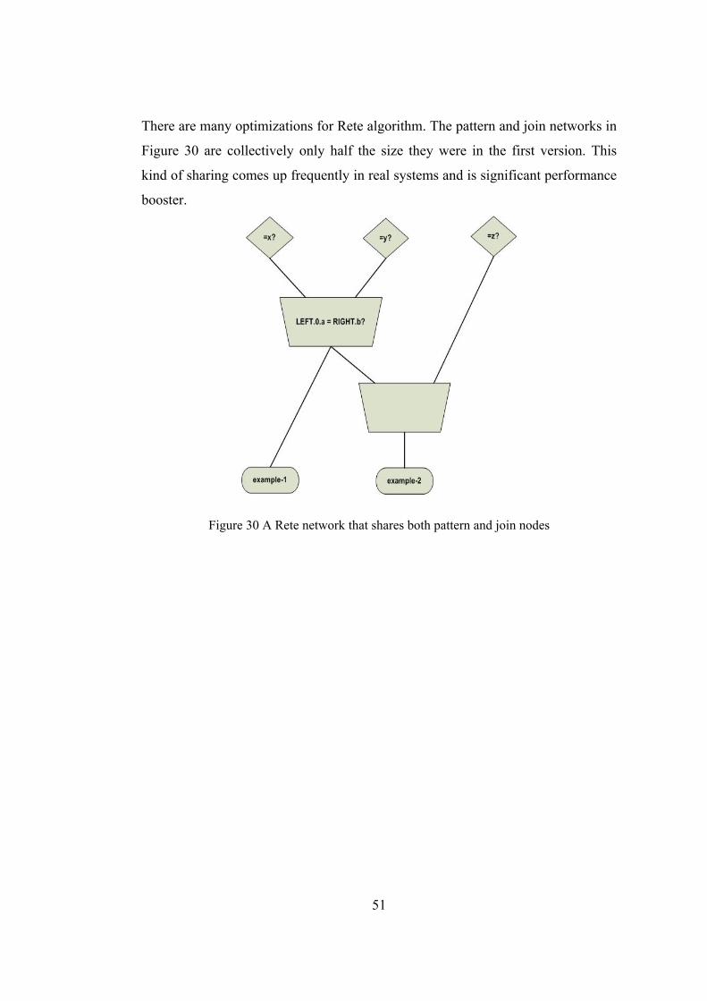
51
There are many optimizations for Rete algorithm. The pattern and join networks in
Figure 30 are collectively only half the size they were in the first version. This
kind of sharing comes up frequently in real systems and is significant performance
booster.
Figure 30 A Rete network that shares both pattern and join nodes

52
CHAPTER 5
CONCLUSION AND FUTURE WORK
In this thesis, fault isolation and service restoration algorithms based on expert
system are presented for medium voltage cable distribution system. In Turkey,
especially in big cities, electric distribution system has been uprating from 10.5 kV
(or 6kV, 15 kV) voltage level to 34.5 kV voltage level for reducing distribution
system losses, robust planning and simple power system operation since 90’s.
Ensuring reliability of sustainable energy was the next goal and TUBITAK
developed a distribution automation system named TUDOSIS. This system has
been implemented and working successfully for about more than ten years in
Istanbul. But during of ten years time, distribution system has expanded without
distribution automation because of lack of funds. The unplanned growth of power
system endangered TUDOSIS unable to work properly. This was the starting point
for the thesis and a new fault isolation algorithm for distribution automation is
proposed.
Proposed fault isolation algorithm has a SCADA based approach that uses the
alarms originating from the protection systems (relays and circuit breakers) and
fault passage indicators through SCADA system. In the core of fault isolation
algorithm, there is a distributed control approach which means automation system
delivers the isolation task between novel RTUs. These RTUs are placed in the
substation that has circuit breaker and relays, are responsible for possible faults in
the manner of an agent based framework (simply every team which is consisted of
distribution transformers has a coach). When a fault occurs, related circuit breaker
will trip and special RTU for this substation will interrogate connected RTUs.
After finding the fault location, it is cleared by opening both side switching
devices and after that, control center software will be informed of the fault
isolation process. In the case of communication problem between RTUs in the

53
feeder and substation, the coach RTUs will hand over the isolation process to
control center software.
Furthermore service restoration is mandatory for sustainable energy quality and
system reliability. In Turkish distribution system for mesh networks expert system
based service restoration algorithm is the right choice. One reason is expert system
solution is fully explainable and consists of operator knowledge. The other reason
is that this approach can preserve specialists’ knowledge to train novice operators.
Proposed approach consists of four steps which are from the related literature and
the operators’ knowledge. These steps are; group restoration (outage area is
considered as whole group), zone restoration (outage area is divided according to
branch points), load transfer (support feeder transfers their loads to adjacent
feeders to increase their load margin) and maximum load restoration (number of
the de-energized loads is minimized).
In the light of these proposed methods, a new distribution automation system will
be designed within two subgroups. First flexible RTU hardware and software
should be implemented considering presented fault isolation approach and new
information and communication technology (ICT) infrastructures. Therefore,
flexible ICT infrastructures should be low-cost, secure, open and reliable to lead
management of smart electricity distribution which is next generation of
distribution concept. Accordingly control center software should be designed
taking into account proposed fault isolation and service restoration functions and
open for ICT hardware solutions (i.e. not only one type of RTU). On the other
hand protection system of the current distribution system will be reconfigured
considering dispersed generation and penetration level of the generation.
Finally ultimate goal of the future project to build a distribution management
system covering distribution automation, demand side management and distributed
generation management.

54
REFERENCES
[1] James Northcote-Green, Robert Wilson, “Control and Automation of Electrical Power Distribution Systems,” in Boca Raton, CRC Press, 2006.
[2] D. Bassett, K. Clinard, J. Grainger, S. Purucker, and D. Ward, “Tutorial Course: Distribution Automation,” IEEE Tutorial Publication 88EH0280-8-PWR, 1988.
[3] N. Ozay, A. N. Guven, A. Buyuksemerci, and M. Fettahlioglu, “Design and Implementation of a Feeder Automation System for Distribution Networks,” PowerTech Budapest 99. International Conference, 29 Aug.-2 Sept. 1999.
[4] N. Ozay, A. N. Guven, A. Tureli, and M. Demiroglu, “Technical and Economic Feasibility of Conversion to a Higher Voltage Distribution,” in Proc. IEE Proc. Gener. Transm. Distrib., September 1995, Vol. 142, No. 5.
[5] Lim, I.H.; Kim, Y.I.; Lim, H.T.; Choi, M.S.; Hong, S.; Lee, S.J.; Lim, S.I.; Lee, S.W.; Ha, B.N.; “Distributed Restoration System Applying Multi-Agent in Distribution Automation System,” in Proc. Power and Energy Society General Meeting - Conversion and Delivery of Electrical Energy , 2008.
[6] M. H. Güçsav, “Distributed Network Architecture and Protocol for Distribution Automation System,” Ms Thesis, Middle East Technical University, Jan. 1997.
[7] G. Ş. Şenyurt, “Design and Implementation of A Unix-Based Master Station Software For Distribution Automation Software,” Ms Thesis, Middle East Technical University, Jan. 1997.
[8] G. G. Seip, “Electrical Installation Handbook”, Volume 1, Heyden &Son Ltd., in London, 1979.
[9] D. M. Staszesky, D. Craig, C. Befus, “Advanced Feeder Automation is Here,” IEEE Power & Energy Magazine, Semptember/October 2005.
[10] M.A.P. Rodrigues, M.T. Schilling, M.B. Do Coutto Filho, “Fault location in electrical power systems using intelligent systems techniques,” IEEE Trans. Power Del., 2001.
[11] Y. M. Park, G. Kim, and J. Sohn, “A logic based expert system (LBES) for fault diagnosis of power systems,” IEEE Trans. Power Syst., Feb. 1997.
55
[12] S.M. Brahma and A.A. Girgis, “Development of adaptive protection scheme for distribution systems with high penetration of distributed generation,” IEEE Trans. Power Del., 2004.
[13] M. Aldeen and F. Crusca, “Observer-based fault detection and identification scheme for power systems,” in Proc. Generation, Transmission and Distribution, IEE Proceedings, 2006.
[14] R. S. Pressman, “Software Engineering: A Practitioner's Approach,” Boca Raton: McGraw-Hill, 2000.
[15] B. Meyer, “Object-Oriented Software Construction,” Prentice Hall, 1997.
[16] K. Aoki, K. Nara, M. Itoh, T. Satoh, H. Kuwabara, “A new algorithm for service restoration in distribution systems,” IEEE Trans. Power Del., July 1989.
[17] Y.-Y. Hsu, H.-M. Huang, “Distribution system service restoration using the artificial neural network approach and pattern recognition method,” in Proc. Generation, Transmission and Distribution, IEE Proceedings, May 1995.
[18] A.E. Eiben ,J.E. Smith, “Introduction to Evolutionary Computing,” Germany, Springer ,2003.
[19] A.C. Santos, A. Delbem, N.G. Bretas, “Energy Restoration For Large-Scale Distribution System Using Ea And A New Data Structure,” in Proc. Power and Energy Society General Meeting - Conversion and Delivery of Electrical Energy in the 21st Century, July 2008.
[20] C.-C. Liu, S.J. Lee, S.S. Venkata, “An expert system operational aid for restoration and loss reduction of distribution systems,” IEEE Trans. Power Syst., May 1988.
[21] Men-Shen Tsai, “Development of an Object-Oriented Service Restoration Expert System with Load Variations”, IEEE Trans. Power Syst., Feb. 2008.
[22] Y. Fukuyama, H. Endo, Y. Nakanishi, “A hybrid system for service restoration using expert system and genetic algorithm”, in Proc. Intelligent Systems Applications to Power Systems, 1996.
[23] V.N.A.L. da Silva, R. Linden, G. F. Ribeiro, “A Framework for Expert Systems Development Integrated to a SCADA/EMS Environment”. in Proc. Intelligent Systems Applications to Power Systems, 2007.
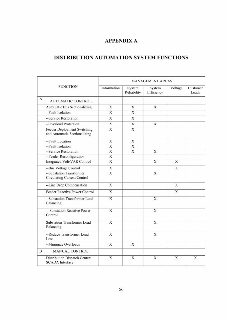
56
APPENDIX A
DISTRIBUTION AUTOMATION SYSTEM FUNCTIONS
FUNCTION MANAGEMENT AREAS
Information System Reliability
System Efficiency
Voltage Customer Loads
A AUTOMATIC CONTROL:
Automatic Bus Sectionalizing X X X --Fault Isolation X X --Service Restoration X X
--Overload Protection X X X Feeder Deployment Switching
and Automatic Sectionalizing X X
--Fault Location X X --Fault Isolation X X --Service Restoration X X X --Feeder Reconfiguration X Integrated Volt/VAR Control X X X
--Bus Voltage Control X X --Substation Transformer
Circulating Current Control X X
--Line Drop Compensation X X
Feeder Reactive Power Control X X
--Substation Transformer Load Balancing
X X
-- Substation Reactive Power Control
X X
Substation Transformer Load Balancing
X X
--Reduce Transformer Load Loss
X X
--Minimize Overloads X X
B MANUAL CONTROL:
Distribution Dispatch Center/ SCADA Interface
X X X X X
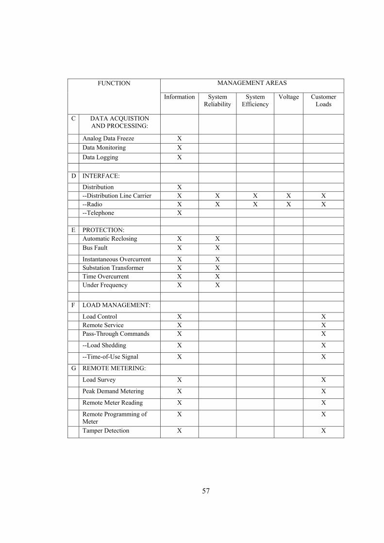
57
FUNCTION MANAGEMENT AREAS
Information System Reliability
System Efficiency
Voltage Customer Loads
C DATA ACQUISTION AND PROCESSING:
Analog Data Freeze X Data Monitoring X Data Logging X
D INTERFACE:
Distribution X --Distribution Line Carrier X X X X X --Radio X X X X X --Telephone X E PROTECTION: Automatic Reclosing X X Bus Fault X X
Instantaneous Overcurrent X X Substation Transformer X X Time Overcurrent X X Under Frequency X X
F LOAD MANAGEMENT:
Load Control X X Remote Service X X Pass-Through Commands X X
--Load Shedding X X
--Time-of-Use Signal X X
G REMOTE METERING:
Load Survey X X
Peak Demand Metering X X
Remote Meter Reading X X
Remote Programming of Meter
X X
Tamper Detection X X