fault detection and isolation of vehicle driveline system
TRANSCRIPT
84
International Journal of Automotive Engineering Vol. 2, Number 2, April 2012
1. INTRODUCTION
Soft computing prospers well with low accuracy
and approaches problem solving based on the human
mind. The guiding principle of soft computing is
utilization of low-accuracy characteristics to solve the
problem and reduce solution costs. Since the methods
using soft computing concepts are considered as
powerful techniques in design of diagnostic systems,
this research is based on it, having special advantages
and features like high accuracy in detecting defects,
determining the size of defects and the ability to use
wavelet transform in obtaining residuals
characteristics and improving efficiency.
In the past decade, artificial neural networks have
been widely used for detection and isolation of
damage in systems. Various fault detection and
isolation techniques began by different researchers in
the early 1970's, and several FDI methods based on
analytical redundancy have been reported since then.
These different techniques can be categorized to
various general methods such as the parameter
estimation, the parity space, the state estimation and
the fault detection filter method. Most of the model-
based patterns use quantitative models to estimate the
states, system parameters or outputs of the system in
order to generate necessary error signals [1].
A main problem associated with such methods is
that, in practice, it is almost impossible to obtain a
model that exactly matches the process treatment
because these methods are mostly limited to linear
systems. Consequently, there is an increasing
tendency for reliable methods of fault detection and
diagnosis for non-linear systems [2]. To solve the
above nonlinearity problem, the research of fault
detection methods has, in recent decades, entered into
a new season by advances of soft computing concepts
such as fuzzy logic, artificial neural networks and
genetic algorithms.
The main advantage of fuzzy logic systems is to
treat system behavior using a set of if-then relations
using both qualitative and quantitative information,
i.e. both knowledge and experience of experts and
measured data respectively [3]. For example, fuzzy
decision-making systems were used in residual
evaluation and also fuzzy rules to either assist or
replace the use of a model for diagnosis [4]. Also,
different applications have shown the ability of
artificial neural networks to design suitable FDI
systems in connection with both predictors of dynamic
nonlinear models as well as pattern classifiers.
Smarter and more capable FDI structures can be
expected from combining the learning capability of
artificial neural networks, the transparency and
interpretability of fuzzy systems, as well as the
optimizing capability of genetic algorithms [5,6].
Considering both problems of residual generation and
evaluation, a soft computing based architecture is
suggested. In particular, a fuzzy-neural FDI structure
is suggested that uses for estimation of fault location
and fault size. The suggested method is then applied to
diagnose the fault components of a driveline system.
Fault Detection and Isolation of Vehicle Driveline System
M. shahab1,* and M. Moavenian2
1 Ph.d. student ,2 Associate professor, faculty of Mechanical Engineering, Ferdowsi University of Mashhad, Iran.
Abstract
Vehicle driveline system and its working accuracy play an important role in the performance of car. The purpose of
this study is to provide an appropriate mechanism for investigating, identifying and determining the position and size
of defects in the vehicle power transmission system. This is based on the patterns of the residual signal, obtained from
a simulated model of the system. Neuro-fuzzy networks have been used in diagnosis of defects because of its specific
advantages and capabilities in pattern recognition. Simulation results demonstrate that the resulting fault detection
system is able to properly locate the fault types under all test conditions, and is sensitive also to fault size. Test and
simulation results using MATLAB software is given at the end.
Keywords: Driveline systems, Simulation, Neuro-fuzzy network, Fault Detection and Isolation (FDI)

85
International Journal of Automotive Engineering Vol. 2, Number 2, April 2012
In order to use the capabilities of neural networks in
system training and fuzzy systems in approximate
reasoning, ANFIS fuzzy-neural systems and fuzzy
clustering techniques have been used in design of fault
detection systems [7,8]. In this paper, due to high
reliability demands of such vehicle system
components, recent fault detection and diagnosis
concepts for these systems are of particular
importance [9]
Attention to driveline system components and their
role in the performance of vehicles, assessment of the
situation is important. This is a complex assembly of
active and reactive dynamic elements. The driveline is
highly non-linear and lightly damped, and thus readily
excited by engine and road inputs. The driveline is a
source of noise, vibration and harshness.
Diagnostic system investigates the health of system
performance and tracks the defects according to the
information received from the desired output signals,
using intelligent methods. Employing a distributed-
lumped elements (Hybrid) model for the vehicle
driveline, validity previously proved [10], plays an
important role in the accuracy of results and the fault
detection in the most of parameter of system makes it
possible. It should be noted that most research in this
area, are related to other vehicle system parts and
components, such as the engine, suspension, braking
and …, so straight comparison with other works is not
possible at this stage.
The organization of the paper is as follows. The
driveline system and application of the proposed FDI
scheme for component faults are described in Section 2.
The proposed FDI approach is described in section 3.
Section 4 includes simulation results that demonstrate the
significance of the approach and conclusion at the end.
2. DRIVELINE MODEL DESCRIPTION
The vehicle driveline system comprises of engine,
clutch, transmission system, drive shafts (propeller
shaft), differential, rear axles and wheels. Figure 1
shows a typical automotive driveline system for a
conventional rear wheel drive vehicle.
The power generated by the internal combustion
engine is transmitted to the road wheels through the
driveline system, sometimes referred to as a power
train or drive train.
Fig. 1. Automotive driveline system for a conventional rear wheel drive vehicle [10]
Fig. 2. The Distributed–Lumped model block diagram for the vehicle driveline system
M. shahab and M. Moavenian

Fault Detection and Isolation of Vehicle Driveline System86
International Journal of Automotive Engineering Vol. 2, Number 2, April 2012
A clutch is usually mounted in the bell housing
between the flywheel and the input shaft of the
gearbox. The role of the clutch is to permit the drive to
be engaged and disengaged. Transmission and
differential which ensure necessary reductions from
the engine speed to the required speed at the road
wheels. The gearbox includes a large number of gears
for speed reduction. The propeller shaft is an assembly
of various components, including the driveshafts,
constant velocity joints and spine joints. The
differential effects a 90 degree transfer of power to
rear axles which engage wheel spindles.
There are many configurations for driveline
system, depending on vehicle type; front wheel drive,
rear wheel drive or four wheel drive, as well as manual
transmission versus automatic transmission, small car
as opposed to vans and light trucks, and through to
heavy goods vehicles.
The behavior of a lumped dynamic system is
governed by a set of ordinary differential equations.
The dynamic behavior of a distributed system can be
similarly stated and governed by a set of partial
differential equations. Physically all systems are
distributed in nature, but for practical purposes they
can be approximated by ordinary differential
equations or by a combination of distributed and
lumped components.
In this study the distributed-lumped (hybrid)
modeling technique (DLMT) is considered for solving
the equations of motion. The block diagram method
and the transfer function method (TFM) will be used
for time and frequency responses of the model
respectively. For modeling of the non-linear
parameters, the describing function technique will be
applied to the driveline model. (To increase the
accuracy and efficiency) [10]
This model was simulated in MATLAB using the
VALUES PARAMETERS CHARACTERS
PARTS
0.3076 kg inertia
Flywheel 0.2 N m s/rad equivalent damping
150 Nm Input torque
527 Nm/radStiffness Clutch
10 Nm/rad Damping
0.003 kg inertia
Gearbox 2 N m s/rad equivalent damping
2.08 Gear ratio
0.0265 kg inertia
Differential 1.0 N m s/rad equivalent damping
4.11 Gear ratio
0.435 mlength First
driveshaft kg inertia
0.985 m length
Second
driveshaft
kg inertia
80 N/ shear modulus
0 Nm/rad damping
0.877 mlength
Axle
halfshaft
kg inertia
N/ shear modulus
0 Nm/raddamping
2 kg Inertia
Wheel Nms/rad damping
7810 Kg/ density
Table 1. Nominal Parameters of Driveline System
Fig. 3. Output torque from the engine
Fig. 4. Vehicle wheel angular velocity and acceleration
87
International Journal of Automotive Engineering Vol. 2, Number 2, April 2012
SIMULINK toolbox for a light diesel truck with a two
piece propeller shaft. The block diagram for the
vehicle driveline used in fault detection is shown in
Fig. 2.
Output torque of the engine is considered as input
and angular velocities and accelerations of vehicle
wheel as two system outputs. (These signals were
selected because they are easily measurable).
Table 1 shows the nominal parameters of driveline
system. Twelve parameters could cause known fault
conditions within the system. These parameters are kc,
Cc, BL, Bg, ng, Bd, nd, Ca, Jg, Jf, Bf and Jd.
Input and output signals are obtained by the
simulation model and are representatives of normal
system behavior. The figures are given below (Fig. 3, 4).
3. THE PROPOSED FDI APPROACH USING
NEURAL NETWORKS - FUZZY
A system that has the capacity of detecting,
isolating, identifying or classifying faults is called a
fault diagnosis system. According to generally
accepted terminology, the fault diagnosis task consists
of the following three steps: fault detection (indicates
that an abnormal behavior has occurred), fault
isolation (determines the type and location of the
failure), and fault analysis (determines the relation
between symptoms and cases of failures).
Furthermore, there are two general opinions in design
of model-based FDI techniques as follows:
1. Generation of serious residuals and symptoms
that contain rich and satisfactory information
about faults. If such symptoms are not
generated successfully, certain fault features
could potentially be lost. (Residual evaluation
becomes relatively easy if residuals are well
designed)
2. Designing powerful fault detection systems
using sophisticated techniques, which reflect
fault specification and adopt a reliable, safe and
optimal decision accordingly, even if the
residuals are not well-designed.
In this paper, we demonstrate that a combination of
the above two viewpoints can have potentially
significant. Improvement to FDI systems, Namely, in
the proposed soft computing based diagnosis system,
because of the successful clustering based modeling,
the residuals regarding specific faults have uniquely
recognizable patterns. Consequently the residuals are
well-designed, and a robust diagnosis system for
residual evaluation can been designed.
The proposed fault detection method is based on
the following:
a. Modeling the normal state of the system.
b. Generating the residuals.
c. Alerting the occurrence of faults in case of
significant differences
d. Identifying the location and size of faults.
Normal state of the system is determined using a
simulated model. For determination of the fault
location and size, ANFIS fuzzy-neural decision
making system has been used.
This structure is the major training routine for
Sugeno-type fuzzy inference systems. Anfis uses a
hybrid learning algorithm to identify parameters of
Sugeno-type fuzzy inference systems. It applies a
combination of the least-squares method and the back
propagation gradient descent method for training FIS
membership function parameters to emulate a given
training data set. Anfis can also be invoked using an
optional argument for model validation [11].
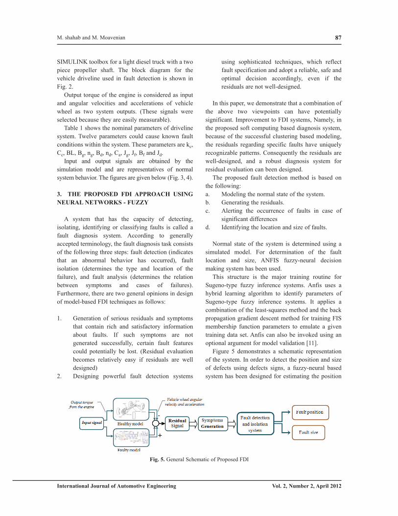
Figure 5 demonstrates a schematic representation
of the system. In order to detect the position and size
of defects using defects signs, a fuzzy-neural based
system has been designed for estimating the position
Fig. 5. General Schematic of Proposed FDI
M. shahab and M. Moavenian
Fault Detection and Isolation of Vehicle Driveline System88
International Journal of Automotive Engineering Vol. 2, Number 2, April 2012
of defects.
The input of system is extracted features from the
residual data and the system output indicates the fault
condition. By changing the desired simulated system
parameters for fault detection, the remainders, which
are the differences of the output signals of the
simulated and the identified system, reveals different
patterns. This will make it easy to identify and isolate
defects [12,13].
Using the samples of the residual signals (healthy
condition), as input data to the neural network,
prolongs the process of network training and causes
bulkiness, plus heavy dependence of results to the
signal amplitude and high sensitivity to noise.
Therefore, to detect defects in the system parameters,
the salient features of any remainders signal, are
derived as signs of defects.
Some of the significant and more effective features
are: Maximum, Minimum, Average, Standard
deviation, Stretch and Skewness of residual signal’s,
using wavelet toolbox and signal frequency
characteristics. [14,15]
The most important advantages of this network are
its compound learning rules and comprehensible
output, making it more efficient than other methods.
To implement the technique, first, a set of rules should
be introduced, so that during training period the
system optimizes shape of membership functions in
the hypothesis part and also optimizes parameters of
the rules part outcomes. The importance here is that
attention should be paid to find appropriate required
data for the system. As a result, adequate membership
functions and rules of ''if – then'' can be chosen for it.
Characteristic signs of defects that have been
obtained in the previous step are considered as input to
the decision-making systems. If these features belong
to a class of defects, the system output will identify the
number that represents the fault. The defects size
estimation is carried out after identification of any
fault by neural network.
It should be mentioned that, sometimes and in some
circumstances, selecting the type of membership
functions in fuzzy systems is difficult. However, the
membership functions shape depends on some
parameters and varying these parameters will change
the shape of membership functions. Use of adaptive
neural learning techniques can be very useful in
choosing optimal membership functions.
This method of learning is very similar to neural
networks and it is applied by passing the training data
through an optimal system of membership functions to
match with the data shape and to model the behavior
of the data.
After forming the membership functions and
supposed ''if – then'' rules of the system, the network
is then taught. Network training continues until the
error is minimized and the system is properly
optimized. Usually by increasing the number of
iterations, the error decreases.
4. SIMULATION RESULTS
Angular velocities and accelerations of vehicle
wheel are two outputs of the driveline system. These
two outputs were chosen as fault indications and
residuals are generated by inconsistency between the
faulty model and the nominal (free-fault) model.
In the present work, faults are simulated on the
process model that was validated in part by comparing
actual experimental data with simulation. Namely the
data extracted by this model are used to simulate the
trained (known) faults.
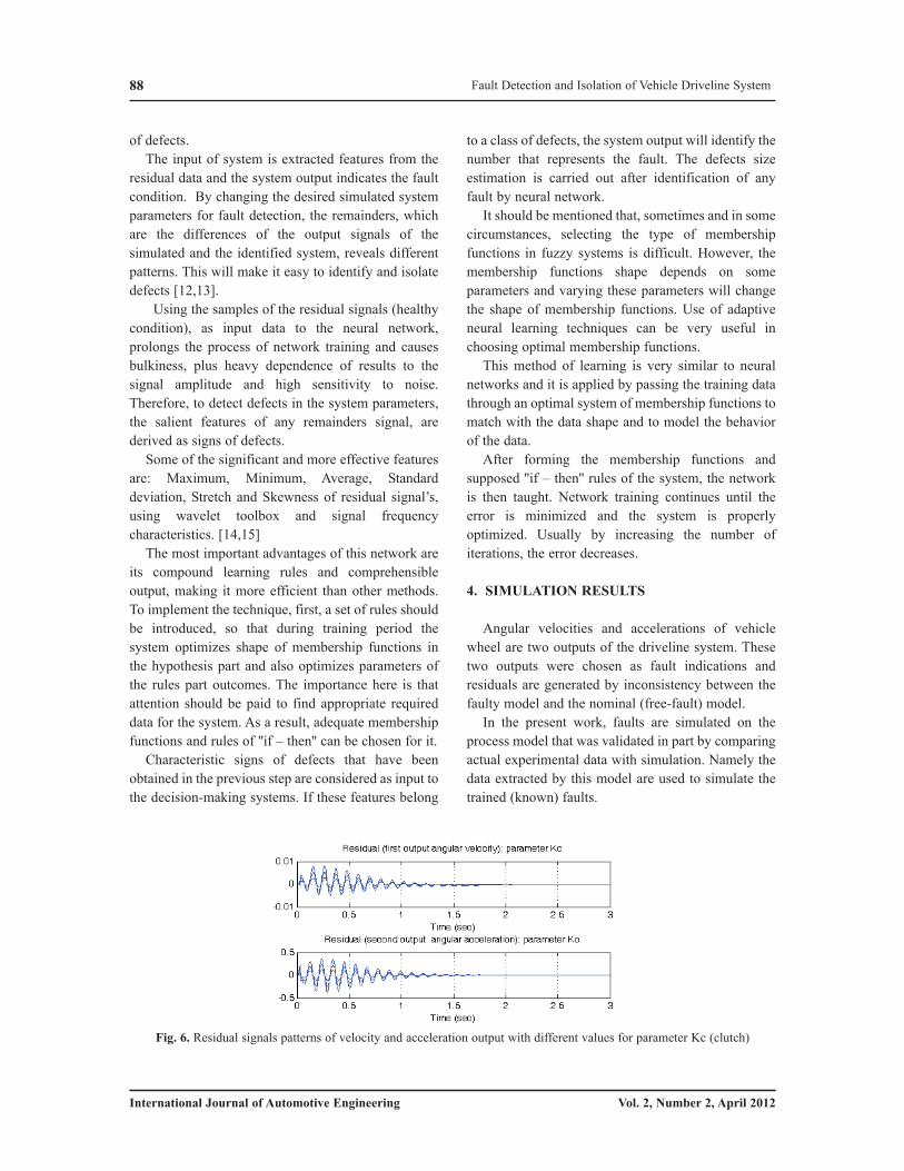
Fig. 6. Residual signals patterns of velocity and acceleration output with different values for parameter Kc (clutch)
89
International Journal of Automotive Engineering Vol. 2, Number 2, April 2012
In this paper, all faults were emulated in software
by applying suitable changes to the parameters of
driveline system in nominal (free-fault) condition.
Each fault type is simulated at various size levels,
varying from 2 to 60 percent. The resulting pairs of
fault types and their symptoms have been used for
design of the local fuzzy agents.
A model based on system identification method is
used to estimate the nominal process output signals.
(When the system is working under healthy condition)
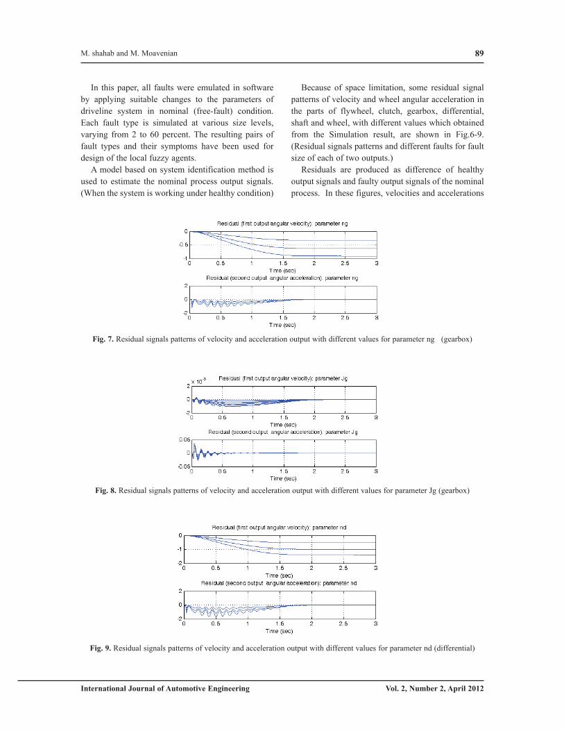
Because of space limitation, some residual signal
patterns of velocity and wheel angular acceleration in
the parts of flywheel, clutch, gearbox, differential,
shaft and wheel, with different values which obtained
from the Simulation result, are shown in Fig.6-9.
(Residual signals patterns and different faults for fault
size of each of two outputs.)
Residuals are produced as difference of healthy
output signals and faulty output signals of the nominal
process. In these figures, velocities and accelerations
Fig. 9. Residual signals patterns of velocity and acceleration output with different values for parameter nd (differential)
Fig. 7. Residual signals patterns of velocity and acceleration output with different values for parameter ng (gearbox)
Fig. 8. Residual signals patterns of velocity and acceleration output with different values for parameter Jg (gearbox)
M. shahab and M. Moavenian
Fault Detection and Isolation of Vehicle Driveline System90
International Journal of Automotive Engineering Vol. 2, Number 2, April 2012
describe the residuals regarding 1st and 2nd outputs, i.e.
angular velocities and accelerations of vehicle wheel,
respectively.
In these figures, the residuals regarding changes of
a specific parameter have a unique pattern and on the
other hand have a different pattern than residuals
regarding change of other parameters.
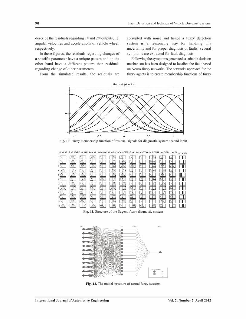
From the simulated results, the residuals are
corrupted with noise and hence a fuzzy detection
system is a reasonable way for handling this
uncertainty and for proper diagnosis of faults. Several
symptoms are extracted for fault diagnosis.
Following the symptoms generated, a suitable decision
mechanism has been designed to localize the fault based
on Neuro-fuzzy networks. The networks approach for the
fuzzy agents is to create membership functions of fuzzy
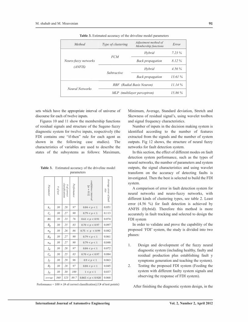
Fig. 11. Structure of the Sugeno fuzzy diagnostic system
Fig. 10. Fuzzy membership function of residual signals for diagnostic system second input
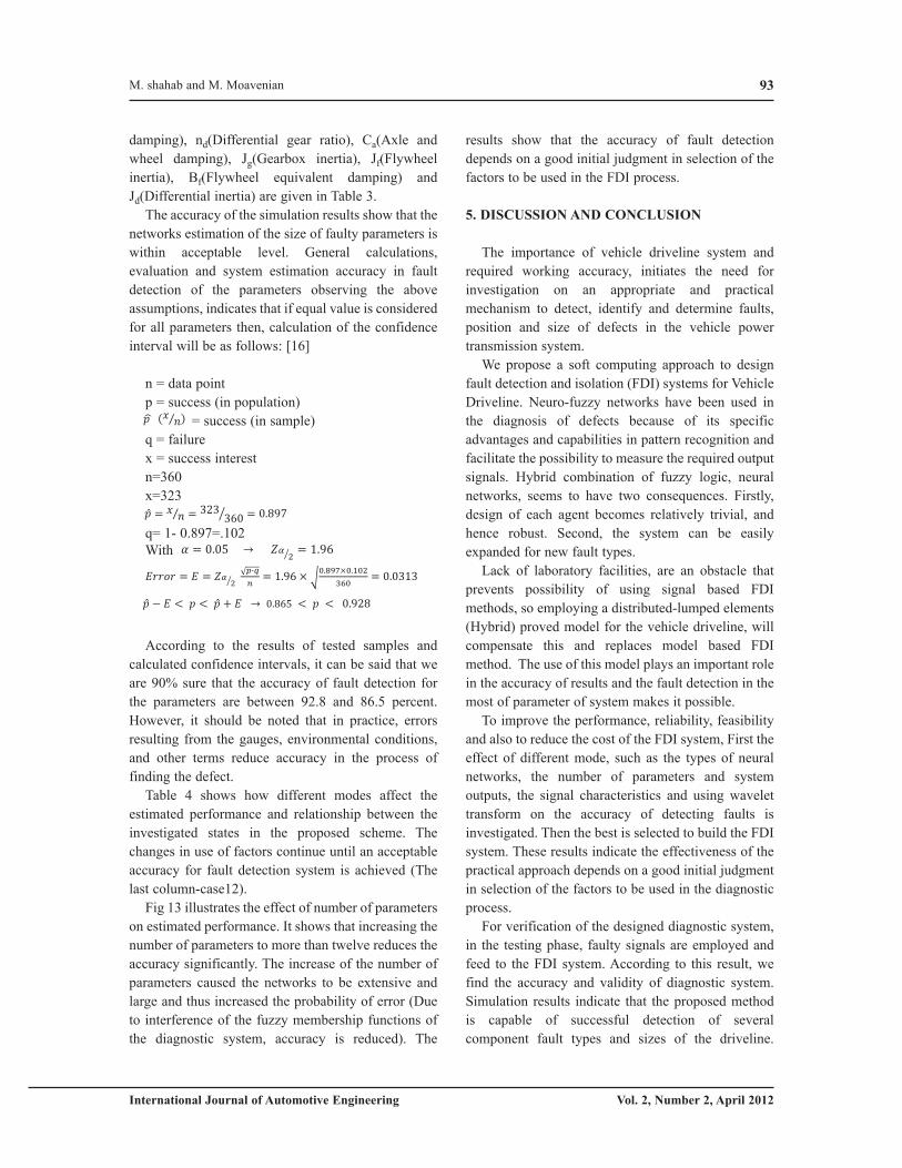
Fig. 12. The model structure of neural fuzzy systems
91
International Journal of Automotive Engineering Vol. 2, Number 2, April 2012
sets which have the appropriate interval of universe of
discourse for each of twelve inputs.
Figures 10 and 11 show the membership functions
of residual signals and structure of the Sugeno fuzzy
diagnostic system for twelve inputs, respectively (the
FDI contains one “if-then” rule for each agent as
shown in the following case studies). The
characteristics of variables are used to describe the
states of the subsystems as follows: Maximum,
Minimum, Average, Standard deviation, Stretch and
Skewness of residual signal’s, using wavelet toolbox
and signal frequency characteristics.
Number of inputs in the decision making system is
identified according to the number of features
extracted from the signals and the number of system
outputs. Fig 12 shows, the structure of neural fuzzy
networks for fault detection system.
In this section, the effect of different modes on fault
detection system performance, such as the types of
neural networks, the number of parameters and system
outputs, the signal characteristics and using wavelet
transform on the accuracy of detecting faults is
investigated. Then the best is selected to build the FDI
system.
A comparison of error in fault detection system for
neural networks and neuro-fuzzy networks, with
different kinds of clustering types, see table 2. Least
error (4.56 %) for fault detection is achieved by
ANFIS (Hybrid). Therefore this method is more
accurately in fault tracking and selected to design the
FDI system
In order to validate and prove the capability of the
proposed ‘FDI’ system, the study is divided into two
phases:
1. Design and development of the fuzzy neural
diagnostic system (including healthy, faulty and
residual production plus establishing fault y
symptoms generation and teaching the system).
2. Testing the proposed FDI system (Feeding the
system with different faulty system signals and
observing the response of FDI system).
After finishing the diagnostic system design, in the
Neur
Ne
Method
ro-fuzzy networ
(ANFIS)
Neural Networks
Type of
Frks
Sub
s M
f clustering
FCM
tractive
RBF (Radial B
MLP (multilay
Adjustment me
Membership fu
Hybrid
Back propag
Hybrid
Back propag
Basis Neuron)
yer perceptron)
Erthod of
unctions
7.2d
8.1gation
4.5d
13.gation
11.
15.
rror
23 %
12 %
56 %
61 %
14 %
86 %
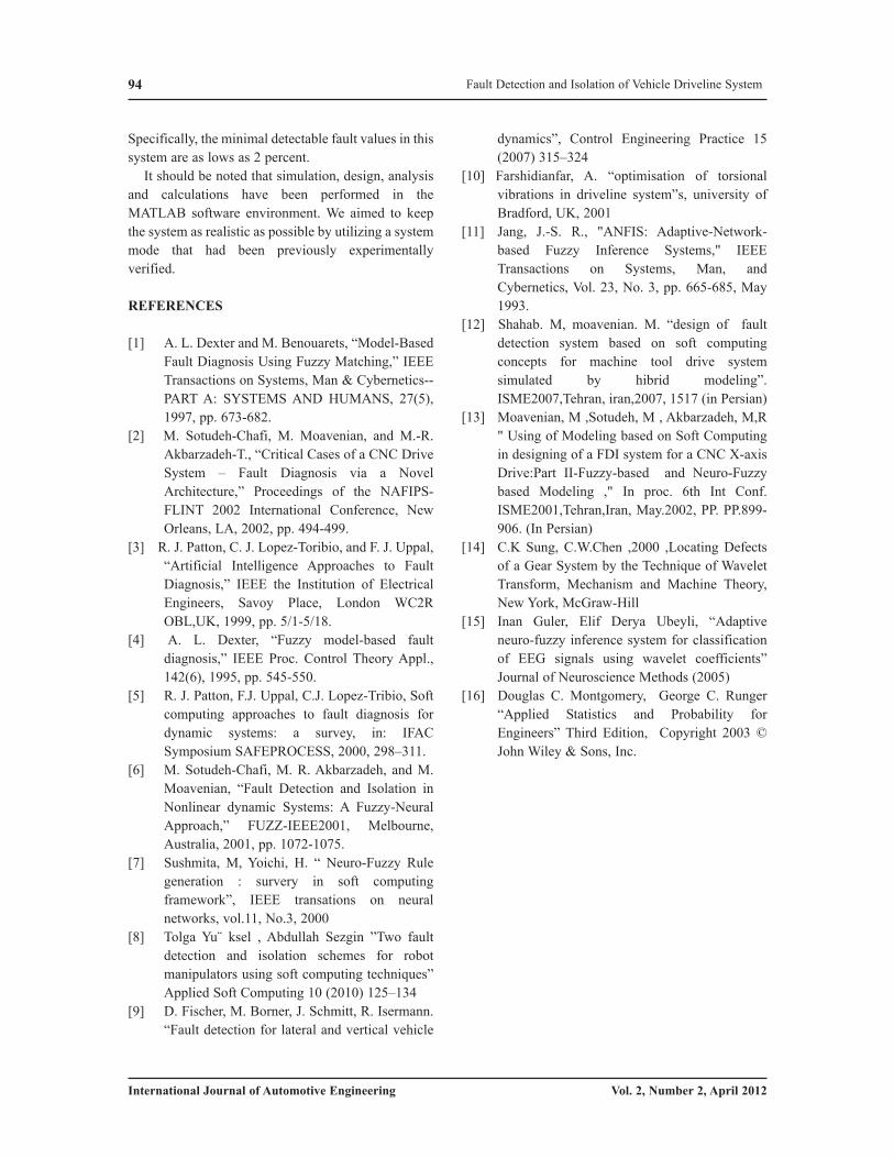
Table 3. Estimated accuracy of the driveline model parameters
Avera
ge erro
r of fa
ult
size
con
fiden
ce interva
l
Perfo
rma
nce
# o
f correct
classifica
tion
s
# o
f test
Pa
ram
eter
0.051 97 28 30
0.113 90 27 30
0.074 76 23 30
0.097 83 25 30
0.082 86 26 30
0.061 90 27 30
0.048 90 27 30
0.072 97 28 30
0.084 83 25 30
0.063 96 29 30
0.045 97 28 30
0.037 100 30 30
0.068 89.7 323 360 average
Performance =
Table 3. Estimated accuracy of the driveline model
parameters
M. shahab and M. Moavenian

Fault Detection and Isolation of Vehicle Driveline System92
International Journal of Automotive Engineering Vol. 2, Number 2, April 2012
testing phase, faulty signals that are generated using a
known faulty model (changing the parameter values
corresponding to a known fault) are employed and
feed to the FDI system. These faulty signals are not
similar to the signals used in the training phase, from
size point of view.
The diagnostic system according to the pattern of
the residual signals available in the memory, will
declare the type and size of the faults.
This test was performed several times and with
considering the number and the system answers, the
fault detection accuracy for each parameter is
estimated (see table 3). For each fault mode, a number
of different fault sizes were tested.
Considering the obtained patterns, detection of
defects in components of the driveline system such as
clutch, gearbox, driveshaft and differential, rear axle
have been studied. Results of identified system wear
and isolated defects in the system parameters kc(Clutch stiffness), Cc(Clutch damping), BL(Gearbox
gear backlash), Bg(Gearbox equivalent damping),
ng(Gearbox gear ratio), Bd(Differential equivalent
mode Case
1
Case
2
Case
3
Case
4
Case
5
Case
6
Case
7
Case
8
Case
9
Case
10
Case
11
Case
12
Sig
na
l chara
cteristics an
d o
utp
uts
output 1
output 2
Maximum
Minimum
Mean
Standard deviation
Stretch
skewness
Wavelet_ symptoms
Perfo
rma
nce o
f Pa
ram
eter
24% 47% 54% 74% 22% 53% 53% 71% 48% 71% 76% 97%
17% 55% 52% 62% 16% 57% 57% 65% 31% 74% 75% 92%
21% 48% 62% 73% 17% 46% 54% 73% 39% 69% 74% 75%
20% 56% 51% 66% 22% 54% 49% 65% 38% 61% 68% 86%
23% 53% 56% 65% 22% 55% 53% 69% 43% 73% 71% 86%
16% 52% 58% 61% 26% 53% 54% 63% 34% 69% 73% 90%
31% 56% 56% 73% 31% 57% 57% 71% 54% 74% 77% 88%
33% 43% 51% 81% 34% 45% 52% 76% 53% 67% 73% 95%
23% 49% 52% 68% 28% 52% 43% 71% 33% 58% 59% 85%
19% 33% 59% 62% 14% 45% 62% 61% 27% 73% 69% 96%
13% 38% 53% 64% 9% 47% 55% 62% 28% 71% 73% 98%
28% 42% 58% 83% 41% 52% 62% 81% 62% 76% 78% 100%
Total average 22% 47% 55% 69% 23% 51% 54% 69% 40% 69% 72% 90%
, used in fault detection process; , unused in fault detection process; every column represents a case study.
Table 4. Influences of different mode on the estimated performance in fault tracking
Fig. 13. Relationships the number of parameters with estimated accuracy of the diagnostic system
93
International Journal of Automotive Engineering Vol. 2, Number 2, April 2012
damping), nd(Differential gear ratio), Ca(Axle and
wheel damping), Jg(Gearbox inertia), Jf(Flywheel
inertia), Bf(Flywheel equivalent damping) and
Jd(Differential inertia) are given in Table 3.
The accuracy of the simulation results show that the
networks estimation of the size of faulty parameters is
within acceptable level. General calculations,
evaluation and system estimation accuracy in fault
detection of the parameters observing the above
assumptions, indicates that if equal value is considered
for all parameters then, calculation of the confidence
interval will be as follows: [16]
n = data point
p = success (in population)
= success (in sample)
q = failure
x = success interest
n=360
x=323
q= 1- 0.897=.102
With
According to the results of tested samples and
calculated confidence intervals, it can be said that we
are 90% sure that the accuracy of fault detection for
the parameters are between 92.8 and 86.5 percent.
However, it should be noted that in practice, errors
resulting from the gauges, environmental conditions,
and other terms reduce accuracy in the process of
finding the defect.
Table 4 shows how different modes affect the
estimated performance and relationship between the
investigated states in the proposed scheme. The
changes in use of factors continue until an acceptable
accuracy for fault detection system is achieved (The
last column-case12).
Fig 13 illustrates the effect of number of parameters
on estimated performance. It shows that increasing the
number of parameters to more than twelve reduces the
accuracy significantly. The increase of the number of
parameters caused the networks to be extensive and
large and thus increased the probability of error (Due
to interference of the fuzzy membership functions of
the diagnostic system, accuracy is reduced). The
results show that the accuracy of fault detection
depends on a good initial judgment in selection of the
factors to be used in the FDI process.
5. DISCUSSION AND CONCLUSION
The importance of vehicle driveline system and
required working accuracy, initiates the need for
investigation on an appropriate and practical
mechanism to detect, identify and determine faults,
position and size of defects in the vehicle power
transmission system.
We propose a soft computing approach to design
fault detection and isolation (FDI) systems for Vehicle
Driveline. Neuro-fuzzy networks have been used in
the diagnosis of defects because of its specific
advantages and capabilities in pattern recognition and
facilitate the possibility to measure the required output
signals. Hybrid combination of fuzzy logic, neural
networks, seems to have two consequences. Firstly,
design of each agent becomes relatively trivial, and
hence robust. Second, the system can be easily
expanded for new fault types.
Lack of laboratory facilities, are an obstacle that
prevents possibility of using signal based FDI
methods, so employing a distributed-lumped elements
(Hybrid) proved model for the vehicle driveline, will
compensate this and replaces model based FDI
method. The use of this model plays an important role
in the accuracy of results and the fault detection in the
most of parameter of system makes it possible.
To improve the performance, reliability, feasibility
and also to reduce the cost of the FDI system, First the
effect of different mode, such as the types of neural
networks, the number of parameters and system
outputs, the signal characteristics and using wavelet
transform on the accuracy of detecting faults is
investigated. Then the best is selected to build the FDI
system. These results indicate the effectiveness of the
practical approach depends on a good initial judgment
in selection of the factors to be used in the diagnostic
process.
For verification of the designed diagnostic system,
in the testing phase, faulty signals are employed and
feed to the FDI system. According to this result, we
find the accuracy and validity of diagnostic system.
Simulation results indicate that the proposed method
is capable of successful detection of several
component fault types and sizes of the driveline.
M. shahab and M. Moavenian
94
International Journal of Automotive Engineering Vol. 2, Number 2, April 2012
Specifically, the minimal detectable fault values in this
system are as lows as 2 percent.
It should be noted that simulation, design, analysis
and calculations have been performed in the
MATLAB software environment. We aimed to keep
the system as realistic as possible by utilizing a system
mode that had been previously experimentally
verified.
REFERENCES
[1] A. L. Dexter and M. Benouarets, “Model-Based
Fault Diagnosis Using Fuzzy Matching,” IEEE
Transactions on Systems, Man & Cybernetics--
PART A: SYSTEMS AND HUMANS, 27(5),
1997, pp. 673-682.
[2] M. Sotudeh-Chafi, M. Moavenian, and M.-R.
Akbarzadeh-T., “Critical Cases of a CNC Drive
System – Fault Diagnosis via a Novel
Architecture,” Proceedings of the NAFIPS-
FLINT 2002 International Conference, New
Orleans, LA, 2002, pp. 494-499.
[3] R. J. Patton, C. J. Lopez-Toribio, and F. J. Uppal,
“Artificial Intelligence Approaches to Fault
Diagnosis,” IEEE the Institution of Electrical
Engineers, Savoy Place, London WC2R
OBL,UK, 1999, pp. 5/1-5/18.
[4] A. L. Dexter, “Fuzzy model-based fault
diagnosis,” IEEE Proc. Control Theory Appl.,
142(6), 1995, pp. 545-550.
[5] R. J. Patton, F.J. Uppal, C.J. Lopez-Tribio, Soft
computing approaches to fault diagnosis for
dynamic systems: a survey, in: IFAC
Symposium SAFEPROCESS, 2000, 298–311.
[6] M. Sotudeh-Chafi, M. R. Akbarzadeh, and M.
Moavenian, “Fault Detection and Isolation in
Nonlinear dynamic Systems: A Fuzzy-Neural
Approach,” FUZZ-IEEE2001, Melbourne,
Australia, 2001, pp. 1072-1075.
[7] Sushmita, M, Yoichi, H. “ Neuro-Fuzzy Rule
generation : survery in soft computing
framework”, IEEE transations on neural
networks, vol.11, No.3, 2000
[8] Tolga Yu¨ ksel , Abdullah Sezgin ”Two fault
detection and isolation schemes for robot
manipulators using soft computing techniques”
Applied Soft Computing 10 (2010) 125–134
[9] D. Fischer, M. Borner, J. Schmitt, R. Isermann.
“Fault detection for lateral and vertical vehicle
dynamics”, Control Engineering Practice 15
(2007) 315–324
[10] Farshidianfar, A. “optimisation of torsional
vibrations in driveline system”s, university of
Bradford, UK, 2001
[11] Jang, J.-S. R., "ANFIS: Adaptive-Network-
based Fuzzy Inference Systems," IEEE
Transactions on Systems, Man, and
Cybernetics, Vol. 23, No. 3, pp. 665-685, May
1993.
[12] Shahab. M, moavenian. M. “design of fault
detection system based on soft computing
concepts for machine tool drive system
simulated by hibrid modeling”.
ISME2007,Tehran, iran,2007, 1517 (in Persian)
[13] Moavenian, M ,Sotudeh, M , Akbarzadeh, M,R
" Using of Modeling based on Soft Computing
in designing of a FDI system for a CNC X-axis
Drive:Part II-Fuzzy-based and Neuro-Fuzzy
based Modeling ," In proc. 6th Int Conf.
ISME2001,Tehran,Iran, May.2002, PP. PP.899-
906. (In Persian)
[14] C.K Sung, C.W.Chen ,2000 ,Locating Defects
of a Gear System by the Technique of Wavelet
Transform, Mechanism and Machine Theory,
New York, McGraw-Hill
[15] Inan Guler, Elif Derya Ubeyli, “Adaptive
neuro-fuzzy inference system for classification
of EEG signals using wavelet coefficients”
Journal of Neuroscience Methods (2005)
[16] Douglas C. Montgomery, George C. Runger
“Applied Statistics and Probability for
Engineers” Third Edition, Copyright 2003 ©
John Wiley & Sons, Inc.
Fault Detection and Isolation of Vehicle Driveline System