fatigue resistant, energy efficient welding (free) disclaimer and proprietary data notice...
TRANSCRIPT

Final Technical Report: Fatigue Resistant, Energy Efficient Welding Project Title: Fatigue Resistant, Energy Efficient Welding (FREE) Award Number: DE-FC36-03ID14462 Project Period: Jan. 1, 2004 through Dec. 31, 2004 Recipient: Caterpillar Inc. P.O. Box 1875 Peoria (Peoria County), Illinois 61656-1875 Project Manager: Keith Egland, (309) 578-2264, [email protected] Principal Investigator: Howard Ludewig, (309) 578-4469,
[email protected] Co-PIs at Team Member Organizations: Lincoln Electric, Dave Barton, (216) 383-8839, [email protected] Ohio State University, Ted Allen, (614) 292-1793, [email protected]

Acknowledgment, Disclaimer and Proprietary Data Notice Acknowledgment: This report is based upon work supported by the U. S. Department of Energy under Award No. DE-FC36-03ID14462. Disclaimer: Any findings, opinions, and conclusions or recommendations expressed in this report are those of the authors and do not necessarily reflect the views of the Department of Energy Proprietary Data Notice: This report does not contain proprietary data (limited rights data), classified information, information subject to export control classification, or other information not subject to release.

Table of Contents Executive Summary 7 I. Introduction 8
I.1. Description of the Technology 8 I.2. Potential Applications and Energy Savings 8
I.2.1. Manufacturing Cost Reduction 9 I.2.2. Improved Machine Performance 10 I.2.3. Energy Savings Realization 11 I.2.4. Environmental Benefit 12
II. Background 13 II.1. Relevant Technologies 13 II.2. Project Team 14
III. Results and Discussions 15 III.1. Synergistic Process and Joint Design 15
III.1.1. Set-Up and Support 15 III.1.2. Steel 16
III.1.2.1. Butt Welds 16 III.1.2.1.1. Experimental Torch Build 16 III.1.2.1.2. Design of Experiments 18
III.1.2.2. Fillet Welds 22
III.1.3. Aluminum 22
III.1.4. High Strength Steel 22
III.1.5. Integration 22 III.2. In-Process Quality Control Tools 23
III.2.1. Weld Geometry Prediction 23 III.2.2. Weld Quality Management 23
III.3. Validation 23 III.3.1. Fatigue Testing 23 III.3.2. Distortion and Residual Stress 24
IV. Accomplishments 24 V. Conclusions 24 VI. Technology Transfer and Commercialization 24

VII. Recommendations 25 References 25

List of Figures Figure 1. Experimental Torch – 1st Generation. 17 Figure 2. Experimental Torch – 2nd Generation. 17 Figure 3. Square Butt Joint in 20-mm Thick Plate. 18 Figure 4. Tandem Narrow Groove Root Pass in 20-mm Plate. 20 Figure 5. Examples of Root and Cover Passes from the 21 Tandem Narrow Groove Design of Experiments. Figure 6. Example weld cost model comparison between bevel groove 22 and narrow groove scenarios. Figure 7. B50 (Mean) Fatigue Curve and Historical Data 24 for A36 Equivalent Steel.

List of Tables Table 1. Summary of Weld-Related Expenditures and Investments for Major 9 Industrial Sectors. Table 2. Anticipated Annual Cost Savings Resulting from FREE 10 Welding Technology. Table 3. Mining Industry Benefits. 10 Table 4. Green House Gas and Criteria Pollutant Emission Reduction 12 - Power Generation. Table 5. Green House Gas and Criteria Pollutant Emission Reduction 12 - Lightweight Transportation. Table 6. Sample Design of Experiments for Tandem Narrow Groove 18 Development.

7
Executive Summary Primary Objectives: The overall goal of the project is the production and quality control of fatigue resistant, energy efficient welds. These welds will produce fatigue life equal to 10X manual weld fatigue, a penetration increase of 100% over conventional, all-position welding capability, a part cycle time improvement of up to 30%, a total energy requirement reduction of 35%, and a distortion reduction of 20%. Project Scope The scope of this program is to meet the primary objectives by utilizing pulsed waveform shaping to affect the heat input and the resultant weld bead geometry. Objectives for this project include: • Achieve the ability to synchronize robotic weave cycles with desired pulsed waveform
shapes to achieve the desired weld bead geometry. • Refine and apply techniques that permit a small amount of data from the specific
process to calibrate models derived from data either in the laboratory or from similar processes or both.
• Develop process parameter relationships and optimized pulsed gas metal arc welding processes for welding of fatigue-critical structures for steel, high strength steel, and aluminum.
• Develop intelligent methods of weld measurement that can accurately predict weld bead geometry from process information.
Results:
1. A Tandem Narrow Groove process concept was validated. 2. An initial robust design of experiments was completed on the Tandem Narrow
Groove process. 3. A rudimentary cost benefit model was developed.
Note: This program was given partial year 1 funding; work was prioritized and then either delayed or cancelled. Ultimately, year 2 and 3 DOE match funding was not available, and the program was terminated. Conclusions: The proposed concept for welding thick section groove welds with the Tandem Narrow Groove process is feasible. Manufacturing cost reduction can be achieved through increased process velocity and reduced material use. Waste stream and energy reductions can be achieved. Technology Transfer and Commercialization: The technology was presented to several Caterpillar business units, and several applications are identified. There is interest in continuing the development of the Tandem Narrow Groove process. Recommendations: Continue the development of the Tandem Narrow Groove and synergistic weave processes outside of this FREE project.

8
I. Introduction I.1. Description of the Technology Caterpillar, Lincoln Electric, and The Ohio State University combined research efforts to increase arc-welding performance and energy efficiency by utilizing pulsed gas metal arc welding (GMAW-P) waveform-shaping technology in conjunction with the weaving capabilities of an industrial robot. Primary goals are to achieve high performance weldments with an attendant reduction in energy consumption and emission generation. This program enables fabricators to take advantage of all the capabilities that inverter power supplies and digital communication between the power supply and the robot controller promise. This program not only addresses new innovative capabilities of robots and power supplies, but also the creation of robust welding procedures to ensure the quality of the welds through process modeling and simulation. The latest in arc welding power supply technology merged with robotic weaving capabilities are able to achieve synergistic effects and optimize the weld bead shape in any position. In addition to the technology needs identified in the Heavy Industry sector below, this project will have spin off effects addressing research needs in other industry sectors. Process technology will address near net shape welding, capability to predict distortion, the effects of residual stress, and technology to assure quality and reduce inspection in the Aerospace sector. In the Petrochemical/Energy Industry sector, the proposed technology will address the “top priority” area of “smarter welding equipment through computerization” and to a lesser extent technology for 3-D inspection and cost effective elimination of manual welding. Other common areas that have direct impact are advanced concepts to promote wetting, fume reduction, energy-efficient processes, and increase efficiency of power supplies. Synergies with the Automotive industry center around light weight structures and environmental friendly processes. Welding processes that are using the current state-of-the-art technology are limited to flat position welding using CV power supplies. For complex weldments (odd shapes other than linear welds), large positioning equipment is required. The synchronous wave shaping and robotic weave to achieve state-of-the-art without expensive equipment is achievable, but requires proper communication between the robot and power supply. By synchronizing the robotic weave cycle and pulsed gas metal arc waveform, these processes can be used synergistically to obtain ideal weld bead shapes with minimum energy input. In order to obtain the ideal weld bead shape, an understanding of the process parameters that affect the weld bead geometry can be obtained using statistical methods (design of experiments). Using statistical methods, robust process parameters can be achieved using a fraction of the experimental trials. I.2. Potential Applications and Energy Savings The FREE (Fatigue Resistant, Energy Efficient) welding technology developed in this program will generate manufacturing cost reductions, improved machine performances,
9
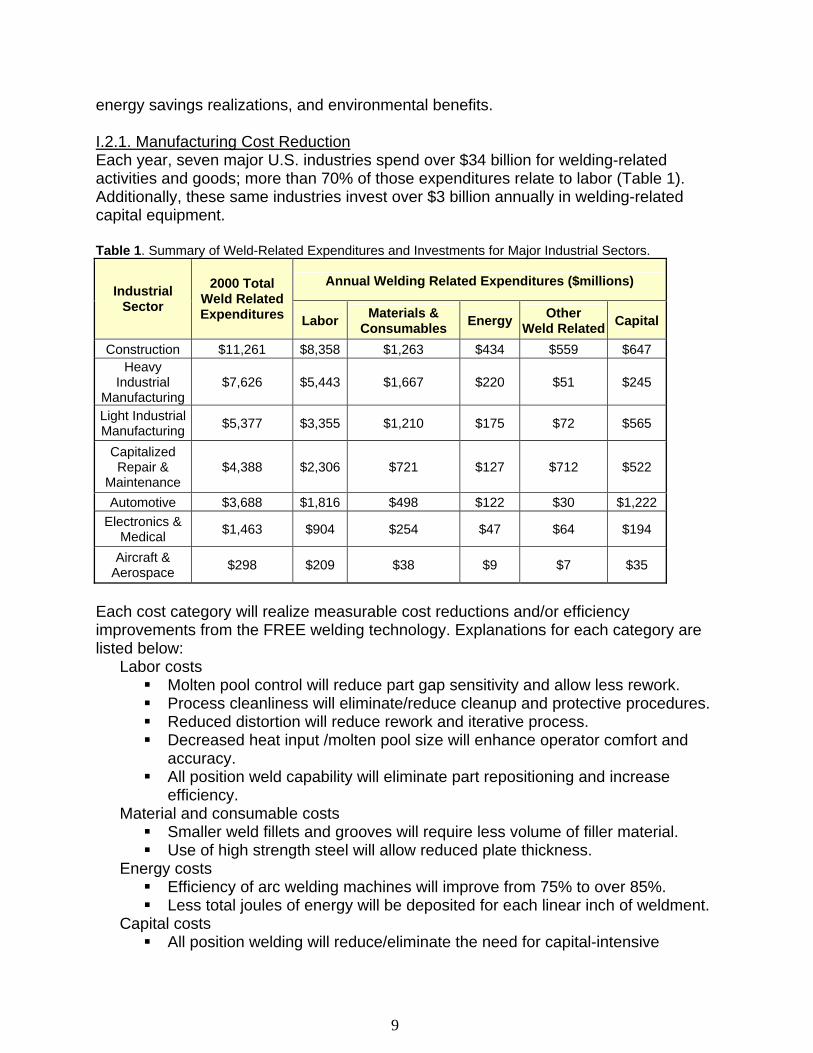
energy savings realizations, and environmental benefits. I.2.1. Manufacturing Cost Reduction Each year, seven major U.S. industries spend over $34 billion for welding-related activities and goods; more than 70% of those expenditures relate to labor (Table 1). Additionally, these same industries invest over $3 billion annually in welding-related capital equipment. Table 1. Summary of Weld-Related Expenditures and Investments for Major Industrial Sectors.
Annual Welding Related Expenditures ($millions) Industrial
Sector
2000 Total Weld Related Expenditures Labor Materials &
Consumables Energy Other Weld Related Capital
Construction $11,261 $8,358 $1,263 $434 $559 $647 Heavy
Industrial Manufacturing
$7,626 $5,443 $1,667 $220 $51 $245
Light Industrial Manufacturing $5,377 $3,355 $1,210 $175 $72 $565
Capitalized Repair &
Maintenance $4,388 $2,306 $721 $127 $712 $522
Automotive $3,688 $1,816 $498 $122 $30 $1,222 Electronics &
Medical $1,463 $904 $254 $47 $64 $194
Aircraft & Aerospace $298 $209 $38 $9 $7 $35
Each cost category will realize measurable cost reductions and/or efficiency improvements from the FREE welding technology. Explanations for each category are listed below:
Labor costs Molten pool control will reduce part gap sensitivity and allow less rework. Process cleanliness will eliminate/reduce cleanup and protective procedures. Reduced distortion will reduce rework and iterative process. Decreased heat input /molten pool size will enhance operator comfort and
accuracy. All position weld capability will eliminate part repositioning and increase
efficiency. Material and consumable costs
Smaller weld fillets and grooves will require less volume of filler material. Use of high strength steel will allow reduced plate thickness.
Energy costs Efficiency of arc welding machines will improve from 75% to over 85%. Less total joules of energy will be deposited for each linear inch of weldment.
Capital costs All position welding will reduce/eliminate the need for capital-intensive

10
positioners. Not every industry will be impacted by equal amounts. Industries with thicker weldments and higher percentages of labor costs will stand to gain the most. Table 1 provides estimates of technology impact for each category of each sector. These percentages are combined in Table 2 and summed for total impact. Table 2. Anticipated Annual Cost Savings Resulting from FREE Welding Technology.
Annual Manufacturing Cost Impact from FREE Welding Technology Industry Sector
Total Impact by Industry ($million) Labor Cost Materials &
Consumables Energy Cost Other Expense Capital
Equipment Cost
Construction $955 -10% -5% -10% - -2% Heavy Ind Mfg $910 -10% -15% -25% - -25% Light Ind Mfg $362 -5% -10% -10% - -10% Capital R&M $101 -3% -2% -5% - -2% Automotive $43 -1% -2% -2% - -1%
Electr/Medical $55 -5% -2% -2% - -2% I.2.2. Improved Machine Performance Improved Machine Performance - In addition to energy efficiency and process control, the FREE technology provides enhanced fatigue resistance. The economic impact of structural failures from fatigue and fracture is astounding; in the late 70’s it was estimated to be 4% of the GDP (4% of $10,208 billion = $400 billion). The vast majority of these failures occur at weldments. With FREE technology, structural stress will be homogenized by smooth-shaped weld beads. This weld shape and residual stress control will enable use of high strength steel and also aluminum for load carrying, weight sensitive structures. Furthermore, all position welding will contribute heavily to flexible manufacturing and mass customization; redundant and unnecessary material will be eliminated and contribute to additional weight reduction. In the case of the mining industry, a 30% weight reduction for structures will provide more payload for each load or haul cycle and a 20-30% increase in profit margins (Table 3). With an annual tonnage for US mining at 14 billion tons, this will generate a profit increase to the industry of over $35million/year. Table 3. Mining Industry Benefits.
Operation Cost/Ton Today
Cost/Ton with FREE Welds
Blasting $0.100 $0.100 Loading $0.100 $0.095 Hauling $0.400 $0.380
Crushing $0.100 $0.100 Total Costs $0.700 $0.675 Selling Price $0.800 $0.800 Margin/Ton $0.100 $0.125 (25% increase)

11
Over 6 million tons of steel goes into construction and mining equipment each year. Aluminum would be a candidate to replace steel in 15-20% of these applications (1.2M tons/yr.) Aluminum structures would weigh about half of steel equivalents, and would generate 0.6M tons/yr of additional aluminum consumption. The added performance value to the customer would absorb the additional material cost and would create almost $1 billion of business to the Aluminum industry. Lifecycle costs would dictate that this material be recycled or reused, supporting the global sustainable manufacturing initiative. Application of Technology - Lightweight structures will be enabled through the use of high strength steels and aluminum. Furthermore, all position welding will enable flexible manufacturing and mass customization to create appropriate manufactured strength for specific customer applications. In the application of mining trucks alone, this generates an annual diesel fuel savings of 3.4 million gallons or 468.5 billion BTU (assuming the average BTU content of diesel fuel to be 137,800 BTU/Gallon). Each year 4500 mining trucks haul 8 billion tons and individually consume on average 20 gallons per hour. Structural weight reduction with equal strength will enable more payloads for the same gross vehicle weight (GVW) and energy consumption. Structures constitute 40% of the empty weight and can be reduced by 25%, netting a 10% decrease in empty weight. Fully loaded trucks carry about two times their empty weight in payload, so the net impact would be 5% additional payload for the same GVW. Annual consumption is:
4500 trucks * 7500 hr/yr/truck * 20 gallons/hr/ = 675 million gallons/yr. A 5% increase in payload per truck would decrease diesel fuel by 3.4 million gallons/yr.
I.2.3. Energy Savings Realization Energy savings realized through this program will emanate primarily from two sources: (1) increased efficiency of weld power supply and (2) reduced energy input for each unit length of weld. Annually, this energy savings is estimated at nearly 3.4 trillion BTU/yr. The seven US industries detailed in Table 1 disburse $1.134 billion annually for welding energy expenditures. Assuming 50% of that spending ($567 million) is for actual electrical power (assume $0.10 per KWH) the total electrical consumption for welding accumulates to 5.7 billion KWH or 19.35 trillion BTU/yr. Assumptions:
New generation power supplies are more energy efficient and will consume 15% less energy than current power supplies to deliver same amount of energy per unit weld length.
New welding process melts less unnecessary metal and requires 10-15% less energy per unit weld length to join parts.
Elimination of part positioning, pre process preparation, and reduction of post

12
process activities (clean-up, protective procedures, and weld repair) will reduce ancillary weld process energy demands 10%.
Net electrical savings for relevant applications is 35%. These savings will be relevant for 50% of industrial applications.
Therefore, a 35% reduction for half of the industrial arc welding energy consumption will yield an annual energy savings of 3.38 trillion BTU / year. I.2.4. Environmental Benefit Historically, energy-related activities account for more than three fourths of the global anthropogenic green house gas inventory. The majority of the green house gas and criteria pollutant emissions from the energy sector which represents one half of energy related emissions, result from stationary fossil fuel combustion at the power plants. Table 4 details the projected emission avoidance derived from the energy efficiencies of the proposed technology. Table 4. Green House Gas and Criteria Pollutant Emission Reduction - Power Generation.
Pollutant Current Emissions (tons)
Projected Emissions(tons)
Emission Avoidance(tons)
Carbon Dioxide 1,543,445 1,003,239 540,206 Sulfur Dioxide 29,365 19,087 10,278 Nitrous Oxide 13,163 8,556 4,607
Combustion of fossil fuel from the transportation industry’s mobile sources represents one-third of the energy related emissions. Table 5 depicts the emission reductions resulting from an annual 3.4 million gallon decrease in combustion of #2 diesel fuel from the light weight mining truck example previously cited. Table 5. Green House Gas and Criteria Pollutant Emission Reduction - Lightweight Transportation.
Pollutant Emission Avoidance (tons) Carbon Monoxide 70
Sulfur Dioxide 12 Nitrous Oxide 366 Hydrocarbons 12
Particulate 7.6 Due to the ability of the proposed technology to control heat input and molten weld pool size, an additional environmental benefit from the reduction of fume and solid process waste will be garnered. A 20% reduction of the projected industry solid waste disposal expenditures of $565,513 represents a reduction of nearly 420 tons of solid waste assuming an average cost of $27.00 per ton of solid waste. Additionally, the proposed technology will use less virgin metal stock. Economies of weld pool dynamics and the reduction of weld repair will simply require the deposition of less filler metal.

13
II. Background II.1. Relevant Technologies Gas Metal Arc Welding (GMAW) is among the most common arc welding processes. It offers continuous electrode feeding and ease of automation. Inverter based technology, introduced in the early 1980’s, provides means for a more controllable process. However, the technology has yet to be widely accepted due to higher equipment costs and the lack of completed process development that takes advantage of the inverter technology. For example, manufacturers such as Lincoln Electric have developed power sources that can detect a short circuit during the process and use this information to reduce the amount of spatter from the process. Dual pulse, variable polarity AC, square-wave AC, and pulse short circuit transfer are some of the features in modern machines. The dual pulse features make GMAW welds appear like gas tungsten arc welding (GTAW) welds albeit with a heavier weld ripple. The digital link between power supply and robot is now becoming the norm, and this will open up new possibilities for synergies between the robot and power supply. In addition, welding consumable manufacturers are developing wider ranges of flux- and metal-cored welding wires, which will enhance performance in specialized applications (e.g. minimum slag for multipass welding applications, improved all-position performance, and/or superior mechanical properties in a wide range of alloys). In welding process research and development, there has recently been extensive development of GMAW processes and technology for welding steel structures for fatigue-critical applications. This work has generated processing techniques, parameter maps and inspection technology that have facilitated the shop-floor production of weldments with high fatigue strength. For example, process response surfaces reported in Barborak et.al.1 allows the simultaneous optimization of weld toe geometry (which has a controlling influence on weld fatigue strength) over multiple process parameters. However, these weld techniques were developed for limited welding positions, tend to have shallow penetration characteristics, and are not optimized for energy and emission reductions. This work has been specifically aimed at constant-current GMAW. Similar process knowledge needs to be generated for welding with pulsed waveform controlled GMAW (GMAW-P). Because of its ability to control heat input and molten weld pool size, the GMAW-P is likely to be an enabling technology for economical production of high fatigue strength welding. The production of welds with optimal toe geometry in less than optimal positions is a key to affordability. Recent work performed at OSU2 has shown that the added flexibility provided by pulsed waveform controlled GMAW is helpful for out-of-position welding of steel structures for fatigue-critical applications. In addition, the waveform shaping techniques will lower energy requirements and emission generation. Edison Welding Institute (EWI) is currently researching waveform control technology for

14
GMAW metal transfer in their arc welding and automation area, but they are not researching how to integrate this capability with the motion of the robot and the robotic weave cycle. In waveform shaping GMAW technology, Kuka robot has developed a robotic weaving technique for the fusion of dissimilar thickness. The KUKA Thermopulse process is a software function to increase the scope of the arc welding application in certain critical applications, e.g. sheet/plate welding of steel and aluminum with widely differing material thicknesses or gap sizes. Japanese power supply manufacturers (OTC, Panasonic) provide waveforms in their power supplies, but no link to adjust your own waveform for a given application, i.e. a different waveform cannot be used on the dwell cycles of the pulse. Hitachi Construction Machinery has developed a process “where a T-joint with a single bevel groove is welded from the bevel groove side without backing and without root gap.”3 This process allows for a full penetration weld from the outside with a acceptable root geometry on the backside. II.2. Project Team To achieve the ambitious goal proposed in this project, the world-class experts in each individual research area have worked as a team for the development of the systematic modeling approach.
Caterpillar Inc. Caterpillar’s Technical Center leads this project. The Peoria, IL facility has 19 acres under roof and nearly 1800 employees who conduct both fundamental and applied research. Over the past five years, Caterpillar staff members have filed nearly 300 patent applications. The Technical Center’s annual budget is approximately $230 million, of which $25 million is spent on materials, structures, and manufacturing processes research, and $5 million is devoted to corporate fabrication-related research. Caterpillar was the prime contractor for three recent NIST ATP projects: FASIP, Engineered Surfaces, and Functionally Graded Materials. The Structural Systems Division has an extensive full-scale fatigue and static strength test laboratory, robotic arc welding and laser laboratories, advanced material characterization facilities, finite element stress analysis capabilities for structural modeling and welding simulation, residual stress measurement capability, and complete on-site load measurement and analysis hardware and software. Lincoln Electric. The David C. Lincoln Technology Center is located at Lincoln’s world headquarters in Cleveland, OH and has been in operation for 1.5 years. The Center was designed to drive new product development as Lincoln enters new markets. Research activities focus on consumables, equipment, and applied technology by utilizing a cross-functional product development process involving marketing, engineering, and manufacturing teams. This product development process includes definition, feasibility, total type, alpha, beta, and production. The Center has several fully

15
functional labs to support research in welding processes, electronics, mechanical testing, chemistry, environmental, and arc physics. Ohio State University. The OSU Welding Engineering program resides in the Edison Joining Technology Center, representing one of the most extensive facilities for welding and joining in the world. Of particular relevance to the proposed waveform development work for this project are a Lincoln Powerwave 455/Fanuc Robot Welding Cell; metallography laboratory with equipment for sample preparation, mounting and polishing, optical microscopy with video and film image capture; arc weld process data acquisition including PC-based data acquisition and control for welding processes, Kodak EktaPro high-speed video system, and Oxford Lasers copper vapor laser strobe illumination system; and Servo-Robot WISC handheld laser scanner with weld metrology software. III. Results and Discussions Work in this program is divided into three main areas: Synergistic Process and Joint Design, In-Process Quality Control Tools, and Validation. Results from these three areas are presented in this section. This program was given partial funding (26% of that expected in year 1) during the first year out of a planned three years. Therefore work was prioritized and then either delayed or cancelled. High priority areas were only delayed with the expectation that partial year 2 and 3 funding would be available, while cancelled work was in expectation that DOE would underfund the whole program. Ultimately, years 2 and 3 DOE match funding was not available, and the program was terminated after only one year. III.1. Synergistic Process and Joint Design In order to fully understand the capabilities of pulsed waveform shaping and the effects of this technology on the weld bead geometry, this module outlined the design of detailed experimental procedures and processes, needed state-of-the-art welding equipment, data analysis, and the implementation into a production capable environment. III.1.1. Set-Up and Support The Set-up and Support Task contains work related to equipment set-up, maintenance, and support throughout the project. Within this program, Lincoln Electric looked into how technologies would be integrated to achieve both an energy efficient power supply and the desired weld profile. This resulted in an experimental laboratory plan for work in this program. The equipment platform included a Fanuc Robot with the Servo wire drive and Heat Wave software combined with some specialty welding software. This lab would support both butt and fillet weld joints for all materials under investigation. The project folder to start acquisition was completed, but the acquisition itself was put on delay, pending available matching DOE funding. No welding or equipment development was initiated.

16
III.1.2. Steel The Steel Task contains all activities related to steel experimentation including design of experiments, baseline experiments, scope experiments, matrix experimentation, data analysis, and documentation. The work is divided into butt joints and fillet joints, the two most common weld joint types for fabrications. Work in the partially funded year one focused on butt joints and the tandem narrow groove process. Caterpillar’s current facilities were sufficient to start on the tandem narrow groove work for butt joints. Work on fillet joints was delayed until adequate DOE matching funds were available. III.1.2.1. Butt Welds. In order to increase joint completion rates while maintaining exceptional joint integrity, tandem narrow groove GMAW with synchronized pulsed wave forms of the two wires was developed. This also provided a means to effectively join square butt joints in thick section materials without bevels, particularly for mild steels. The initial phases of the experimentation and development of this process are detailed below. III.1.2.1.1. Experimental Torch Build. In order to meet goals, an experimental torch was designed and built by retrofitting an existing torch (see Figure 1). This torch employed an adjustable contact tip that would allow for the directional control of arc energy into the root corners of the square butt joint. This control enabled the contact tips to be ‘swiveled’ in a 360-degree range allowing for control of angle in any direction. Modifications were made to an existing twin wire torch to allow for the capability to control the arc energy. This torch contained new hardware specific to the narrow groove process along with the modification of the existing system hardware. The nozzle had a loose fit due to increasing of the ID to allow for new hardware. A rubber epoxy compound along with thread tape was used to allow the nozzle to fit securely onto the torch. The torch was mounted to the robotic arm, and the twin wire process was activated with a contact tip to work distance of 21 mm to accommodate the new hardware. Initially the process would not work properly, and it was determined that the hardware, contact tips and adjusting hardware were contacting the inside of the gas nozzle. A second-generation experimental torch was built by insulating the adjusting hardware with glass tape (see Figure 2). Thereafter, the process proceeded to work properly.

17
Figure 1. Experimental Torch – 1st Generation.
Figure 2. Experimental Torch – 2nd Generation.
Test passes were conducted, and the torch appeared to be sound enough to handle the light duty cycle involved with process experimentation and prove-out. Typical conditions were:
Wire feed rate of 9 meters/min. on each wire.

18
Arc length correction of 22-percent. Travel rate of 75 cm/min.
These settings generated a feedback voltage of 26 volts and a feedback current of 238 amps over a running time of 20 seconds. No sign of heat concerns with respect to extended contact tips or epoxy materials being exposed to exceedingly high temperatures for weld times were encountered during experimentally tested weld lengths. III.1.2.1.2. Design of Experiments. Critical characteristics were determined with regard to producing sound square butt joints in thick plate, and these variables were adjusted between two possible level settings each. This generated a matrix consisting of 64 weld tests. Figure 3 shows the joint geometry and a 25-mm contact tip to work distance and 20mm thick plate. At times (see Table 6) a contact tip to work distance (CTWD) of 21-mm was used with a 20mm plate in order to test the robustness of the process with regard to proximity of the contact tips and nozzle to the base material.
Figure 3. Square Butt Joint in 20-mm Thick Plate.
Table 6. Sample Design of Experiments for Tandem Narrow Groove Development.
Std Order
Run Order
Center Pt Blocks
Cont Tip Angle
(Trans.)
Cont Tip Angle
(Long.)
Cont Tip Separation
Root Opening CTWD WFR % Arc
LengthTravel Rate
1 1 1 1 0 0 low 8 22 8 22 high 51 2 1 1 0 84.7 low 8 25 9 15 low 4 3 1 1 1.5 84.7 low 8 22 8 22 high 60 4 1 1 1.5 84.7 low 14 25 9 15 high 38 5 1 1 1.5 0 high 8 22 9 22 high 43 6 1 1 0 84.7 low 14 22 9 22 high 22 7 1 1 1.5 0 high 8 25 8 22 high

19
The initial design of experiment matrix was set up to begin to define the boundaries for robust process design. The most critical basic parameters were varied between a high and a low setting to determine their individual effects on joint quality. For the matrix, experimental values not specifically mentioned in Table 6 are as follows:
The contact tip separation setting at a longitudinal angle of 84.7 degrees was 14-mm and at 0 degrees was 19-mm (low settings).
The contact tip separation setting at a longitudinal angle of 84.7 degrees was 17-mm and at 0 degrees was 22-mm (high settings).
Travel Rates ranged from a rate of 50 cm/min up to 75 cm/min. The percent arc length correction was adjusted due to the fact that the low
setting was too low for process stability and was adjusted for the execution of the matrix to 17% arc length correction.
Due to the nature of the torch build and the contact separation having to be set by a high temperature epoxy, the matrix was not run randomly. The first half was run in random order, but only for low contact separation settings. The torch then had to be cut, the contact tip separation increased, shimmed, and then re-epoxied prior to continuing with the experimental matrix. The experiments were prepared as seen in Figure 3 per the condition stated in the matrix. A root pass was performed over the entire length of the weld specimen (300-mm in length). The subsequent pass was a tie-in pass to evaluate the ease as to which a subsequent pass would fuse to the first pass. Baseline experiments had shown that with the contact tip angles adjusted to the walls of the square butt joint that there could be instances of ‘scalloping’ or erosion of the joint wall, and there were concerns this could adversely affect the proper complete fusion of subsequent passes. Observations of the tandem narrow groove process during the experiments were documented. The most severe discontinuities in the process arose from two main issues. The first occurred at the lower contact tip to work distance when the angles of the contact tips were at the maximum traverse angle. This condition placed the ends of the contact tips into close proximity to the corners of the square butt joint. While the arc was established, there would be an intermittent arcing between the end of the contact tip and the corner of the square butt joint. This arcing was visible and audible to the operator and also was visible on the surface of the parent material after welding as well as on the bead face of the resultant weld. Noticeable loss of fusion to the sidewall could be observed where the mark on the parent plate indicated the arcing phenomenon. The second in-process discontinuity arose from the general geometry of the torch, nozzle, and the deep groove of the square butt joint. Proper shielding of the weld pool became a continual problem particularly in conditions of higher contact tip to work distance and high travel speeds. This would be visible upon inspecting the weld joint immediately after welding due to the weld appearing discolored and the presence of gross porosity. Improvements in shielding or potentially a change in nozzle as the joint fills up may need to be considered prior to any further experimentation to eliminate this potential noise factor.

20
Visual inspection of each specimen upon completion noted the tendency for a prominent centerline to be visible in the weld (see Figure 4). Due to the highly stressed nature of this joint configuration and the narrow geometry of the joint, the conditions were optimum for centerline hot cracking. This did occur in minor instances but could become more problematic as the experimentation moves into more advanced materials. All 64 experiments in the matrix were executed in the above stated fashion. Specimens were completed, identified, marked for cross-sectioning, and photographed (see Figure 4). The specimens were then sectioned once in the area where only a root pass was present, and once in the area where a subsequent pass could be evaluated. The specimens were then polished, etched, and photographed for further analysis and evaluation.
Figure 4. Tandem Narrow Groove Root Pass in 20-mm plate.

21
(a) (b)
(c) (d)
(e) (f) Figure 5. Examples of Root and Cover Passes from the Tandem Narrow Groove Design of Experiments.

22
Examples of some of the resultant macroscopy appear in Figures 5(a)-5(f). Measurements were taken to evaluate the percent fusion along each sidewall. Image Pro Discovery was used to electronically measure the features to determine percent fusion along the sidewall and the amount of scallop present in each sample. As can be seen in Figure 5(e), scalloping produced significant erosion of the sidewall due to the condition of high contact tip to work and high transverse contact tip angle. A simple weld cost model was developed to validate the potential savings of a tandem narrow groove welding process (see Figure 6). In this example, a savings of approximately 60% is predicted.
Figure 6. Example weld cost model comparison between bevel groove and narrow groove scenarios.
III.1.2.2. Fillet Welds. This work was planned to start after the Lincoln Electric Lab had been set-up. This work was delayed until DOE matching funds had been allocated. III.1.3. Aluminum Aluminum was structured much the same as Task 2 with a focus on aluminum. This work was cancelled due to lack of DOE funding III.1.4. High Strength Steel High Strength Steel was structured similarly to Tasks 2 and 3 with a focus to replicate the Task 2 Steel results on high strength steel in years 2 and 3, which did not occur due to the termination of the program. III.1.5. Integration The Integration task contained the integration and demonstration activities for the module, including the transfer of the knowledge obtained from the research lab environment to the production floor and the environmental impact of the new technology through an environmental cost accounting system. The transfer from lab to production floor issues was year 3 work, and thus did not occur with the termination of the program. Ohio State was poised to develop an environmental cost accounting system with an available graduate student, but expected DOE funding did not occur.

23
III.2. In-Process Quality Control Tools The In-process Quality Control Tools Module contains work for maintaining the quality of the welding processes and procedures derived from Synergistic Process and Joint Design Module. III.2.1. Weld Geometry Prediction Weld Geometry Prediction involves using the process and laser vision data to develop models for the prediction of weld bead geometry and to ensure the fatigue resistant welding is being performed using the lowest amount of energy possible to maintain the quality. This work was delayed due to lack of DOE funding. III.2.2. Weld Quality Management The Weld Quality Management Module involves the integration of welding data and knowledge into database applications. Gathering the knowledge from the weld geometry prediction model and data from vision sensors, weld quality can recorded and documented in a central location. This work was delayed due to lack of DOE funding. III.3. Validation Validation will assure that the welding processes and parameters from this research perform to the expected fatigue resistant criteria, and consists of two tasks, (1) Fatigue Testing and (2) Distortion and Residual Stress. III.3.1. Fatigue Testing This task includes all of the fatigue tests for the various experiments in this project. Fatigue testing will be performed on varying thickness and joint configurations of all three material types. The baseline fatigue benchmark was established, but due to limited DOE funding, fatigue testing of the new processes did not occur. The fatigue baseline for subsequent fatigue work here is based upon the British Standard BS 7608 for manual arc welding. An F class weld joint (butt joint weld with a backing strip) was chosen as the baseline for this program. Historical data verifies this baseline (see Figure 7).

24
10
100
1000
1.0E+04 1.0E+05 1.0E+06 1.0E+07 1.0E+08
Number of Cycles
Stre
ss R
ange
, MPa
Figure 7. B50 (Mean) Fatigue Curve and Historical Data for A36 Equivalent Steel.
III.3.2. Distortion and Residual Stress Distortion and Residual Stress utilize Caterpillar’s Virtual Fabrication Technology (VFT) state-of-the art simulation techniques to predict residual stress in the weld. This work was delayed due to lack of DOE funding. IV. Accomplishments
1. A Tandem Narrow Groove process concept was validated. 2. An initial robust design of experiments was completed on the Tandem Narrow
Groove process. 3. A rudimentary cost benefit model was developed.
V. Conclusions The proposed concept for welding thick section groove welds with the Tandem Narrow Groove process is feasible. Manufacturing cost reduction can be achieved through increased process velocity and reduced material use. Waste stream and energy reductions can be achieved. VI. Technology Transfer and Commercialization The technology was presented to several Caterpillar business units, and several applications are identified. There is interest in continuing the development of the Tandem Narrow Groove process.

25
VII. Recommendations Continue the development of the Tandem Narrow Groove process and the synergistic weave process outside of the FREE project. References
1. D. Barborak, R. Richardson, D. Farson, H. Ludewig (1999) “Development of Empirical Models for GMAW Fillet Weld Geometry”, AWS Conference, American Welding Society, St. Louis, MO.
2. B. Baughman, K. Sneary, J. Zook, (2003)“Effect of GMAW-P Parameters on Weld Geometry”, Poster Presentation, AWS Conference, American Welding Society, to be published.
3. T. Takatani et al. (2002) “Bulldozed-Out Bead Welding Process for a T-Joint,” IIW Commission XII Intermediate Meeting.