fatigue limit of ti6al4v alloy produced by selective laser ... · fatigue limit of ti6al4v alloy...
TRANSCRIPT
ScienceDirect
Available online at www.sciencedirect.com
Available online at www.sciencedirect.com
ScienceDirect
Structural Integrity Procedia 00 (2016) 000–000 www.elsevier.com/locate/procedia
2452-3216 © 2016 The Authors. Published by Elsevier B.V. Peer-review under responsibility of the Scientific Committee of PCF 2016.
XV Portuguese Conference on Fracture, PCF 2016, 10-12 February 2016, Paço de Arcos, Portugal
Thermo-mechanical modeling of a high pressure turbine blade of an airplane gas turbine engine
P. Brandãoa, V. Infanteb, A.M. Deusc* aDepartment of Mechanical Engineering, Instituto Superior Técnico, Universidade de Lisboa, Av. Rovisco Pais, 1, 1049-001 Lisboa,
Portugal bIDMEC, Department of Mechanical Engineering, Instituto Superior Técnico, Universidade de Lisboa, Av. Rovisco Pais, 1, 1049-001 Lisboa,
Portugal cCeFEMA, Department of Mechanical Engineering, Instituto Superior Técnico, Universidade de Lisboa, Av. Rovisco Pais, 1, 1049-001 Lisboa,
Portugal
Abstract
During their operation, modern aircraft engine components are subjected to increasingly demanding operating conditions, especially the high pressure turbine (HPT) blades. Such conditions cause these parts to undergo different types of time-dependent degradation, one of which is creep. A model using the finite element method (FEM) was developed, in order to be able to predict the creep behaviour of HPT blades. Flight data records (FDR) for a specific aircraft, provided by a commercial aviation company, were used to obtain thermal and mechanical data for three different flight cycles. In order to create the 3D model needed for the FEM analysis, a HPT blade scrap was scanned, and its chemical composition and material properties were obtained. The data that was gathered was fed into the FEM model and different simulations were run, first with a simplified 3D rectangular block shape, in order to better establish the model, and then with the real 3D mesh obtained from the blade scrap. The overall expected behaviour in terms of displacement was observed, in particular at the trailing edge of the blade. Therefore such a model can be useful in the goal of predicting turbine blade life, given a set of FDR data. © 2016 The Authors. Published by Elsevier B.V. Peer-review under responsibility of the Scientific Committee of PCF 2016.
Keywords: High Pressure Turbine Blade; Creep; Finite Element Method; 3D Model; Simulation.
* Corresponding author. Tel.: +351 218419991.
E-mail address: [email protected]
Procedia Structural Integrity 2 (2016) 3158–3167
Copyright © 2016 The Authors. Published by Elsevier B.V. This is an open access article under the CC BY-NC-ND license (http://creativecommons.org/licenses/by-nc-nd/4.0/).Peer review under responsibility of the Scientific Committee of ECF21.10.1016/j.prostr.2016.06.394
10.1016/j.prostr.2016.06.394
Available online at www.sciencedirect.com
ScienceDirect
Structural Integrity Procedia 00 (2016) 000–000 www.elsevier.com/locate/procedia
2452-3216 © 2016 The Authors. Published by Elsevier B.V. Peer-review under responsibility of the Scientific Committee of ECF21.
21st European Conference on Fracture, ECF21, 20-24 June 2016, Catania, Italy
Fatigue limit of Ti6Al4V alloy produced by Selective Laser Sintering
M. Benedetti a, M. Cazzolli a, V. Fontanari a, M. Leoni b
a Department of Industrial Engineering, University of Trento, Via Sommarive 9 , 38123 Trento (IT)
b Department of Civil, Enviromental and Mechanical Engineering, University of Trento, Via Mesiano 77,38123 Trento (IT)
Abstract
3D printing is an advanced manufacturing technology for producing metal components, and titanium is a typical alloy that is used in this technique. Some limitations and peculiarity should be considered during the design of components by additive manufacturing. We adopted the most common technique to produce the samples, the selective laser sintering (SLS). In this case the remaining porosity and the surface roughness are affecting negatively the fatigue life. In this study the effects of porosity and surface roughness were studied by performing push-pull tests (R=-1) in a Rumul resonant machine to evaluate the fatigue limit in different conditions. Samples were built by SLS from Ti64 ELI biomedical grade powder. After building, all samples were thermal treated at 670°C to relax residual stresses due to the building process. At this step the microstructure was characterized, it was found to be martensitic (α’). A first lot of samples, as benchmark, was tested in this condition and in the present work are simply called “as built”. Part of the samples were treated by hot isostatic pressing (HIP), by performing this process we obtained the full density, removing the pores still present in the microstructure. The HIP was performed at 920°C, so not only the density was modified by this process, but also the microstructure. The HIP worked as a thermal treatment in the α+β field and the result is that the microstructure is extremely different from the previous condition. It is a lamellar α+β microstructure. To have a significant comparison between the results part of the remaining samples was thermal treated at the same temperature and for the same holding time as for the hipped samples to obtain the same microstructure, maintaining the residual porosity typical of the SLM process. Wohler curves were determined from push-pull test to have a direct comparison of the fatigue performance between the different conditions. © 2016 The Authors. Published by Elsevier B.V. Peer-review under responsibility of the Scientific Committee of ECF21.
Keywords: Additive manufacturing; SLM; 3D printing; Ti64, fatigue, powder metallurgy.
2 M.Benedetti et al./ Structural Integrity Procedia 00 (2016) 000–000
1. Introduction
Additive manufacturing is nowadays a widespread technology used to realize components with intricate geometries where lightness and good mechanical properties are required for special applications [1], [2]. Passing from a rapid prototyping technique to a rapid manufacturing technique selective laser melting (SLM) has been established as one of the most used 3D printing technique. Titanium is commonly processed by SLM for biomedical applications and in the field of aerospace engineering. The most known alloy is the Ti6Al4V also called Titanium Grade 5. Because of its high mechanical properties and low density, it represents an extremely interesting choice for many applications where lightness is required. The 3D printing process of Ti64 components starts from micrometric powder particles that are fused by a laser beam and solidified layer by layer to build a particular geometry. This technology applied to material as titanium allows to go beyond the limits of the conventional manufacturing technology. By SLM it is possible to create density gradients inside the same metal component and produce engineered surfaces directly during the buildup [3]. This aspect is particularly important for biomedical application, in this case the density gradient and the creation of open cellular structure can decrease the apparent Young’s modulus to reach the value of the bone’s one [4]. The creation of engineered surfaces should avoid secondary operation as the coating deposition, improving the adhesion of the surface roughness. Anyway there are some negative aspects that should be considered for a good design for the SLM process. During the component buildup the repetitive thermal cycles used to solidify each layer causes some important consequences on the metal component created by SLM. First of all the component at the end of the process has a high concentration of residual stresses that must be relieved before any other secondary operation is made. Because of the high cooling rate, the microstructure of the alloy is α’ martensite, a metastable phase peculiar of the α+β alloy as Ti64. If necessary a heat treatment at temperature near the beta transus, that is around 980°C, can bring to a lamellar α+β microstructure and subsequently to an increase of the maximum elongation [5]–[7]. As any other defect, pores inside the microstructure act as stress concentrators when a load is applied to the component. In this case pores can be closed only with a hot isostatic pressing (HIP), a process that since the beginning of the industrial use of the powder metallurgy products has been adopted to achieve the full density. The component is heated in a furnace to a temperature below the melting point and plastically deformed by the application of high pressure reaching the full density. [8]–[10]. The HIP process should be a good answer to improve the fatigue limit and have higher expectancy from this point of view.
2. Experimental details and procedures
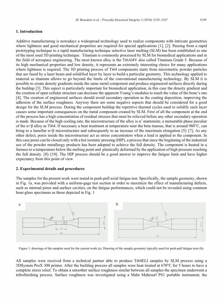
The samples for the present work were tested in push-pull axial fatigue test. Specifically, the sample geometry, shown in Fig. 1a, was provided with a uniform-gage test section in order to maximize the effect of manufacturing defects, such as internal pores and surface cavities, on the fatigue performances, which could not be revealed using common hour-glass specimens as those depicted in Fig. 1
All samples were received from a technical partner able to produce Ti64ELI samples by SLM process using a 3DSystem ProX 300 printer. After the building process all samples were heat treated at 670°C for 5 hours to have a complete stress relief. To obtain a smoother surface roughness similar between all samples the specimen underwent a tribofinishing process. Surface roughness was investigated using a Mahr Mahrsurf PS1 portable instrument, the
Figure 1: drawings of the samples used for the current work (a). Drawing of the sample geometry tipically used for push-pull fatigue tests (b).
Copyright © 2016 The Authors. Published by Elsevier B.V. This is an open access article under the CC BY-NC-ND license (http://creativecommons.org/licenses/by-nc-nd/4.0/).Peer-review under responsibility of the Scientific Committee of ECF21.
M. Benedetti et al. / Procedia Structural Integrity 2 (2016) 3158–3167 3159
Available online at www.sciencedirect.com
ScienceDirect
Structural Integrity Procedia 00 (2016) 000–000 www.elsevier.com/locate/procedia
2452-3216 © 2016 The Authors. Published by Elsevier B.V. Peer-review under responsibility of the Scientific Committee of ECF21.
21st European Conference on Fracture, ECF21, 20-24 June 2016, Catania, Italy
Fatigue limit of Ti6Al4V alloy produced by Selective Laser Sintering
M. Benedetti a, M. Cazzolli a, V. Fontanari a, M. Leoni b
a Department of Industrial Engineering, University of Trento, Via Sommarive 9 , 38123 Trento (IT)
b Department of Civil, Enviromental and Mechanical Engineering, University of Trento, Via Mesiano 77,38123 Trento (IT)
Abstract
3D printing is an advanced manufacturing technology for producing metal components, and titanium is a typical alloy that is used in this technique. Some limitations and peculiarity should be considered during the design of components by additive manufacturing. We adopted the most common technique to produce the samples, the selective laser sintering (SLS). In this case the remaining porosity and the surface roughness are affecting negatively the fatigue life. In this study the effects of porosity and surface roughness were studied by performing push-pull tests (R=-1) in a Rumul resonant machine to evaluate the fatigue limit in different conditions. Samples were built by SLS from Ti64 ELI biomedical grade powder. After building, all samples were thermal treated at 670°C to relax residual stresses due to the building process. At this step the microstructure was characterized, it was found to be martensitic (α’). A first lot of samples, as benchmark, was tested in this condition and in the present work are simply called “as built”. Part of the samples were treated by hot isostatic pressing (HIP), by performing this process we obtained the full density, removing the pores still present in the microstructure. The HIP was performed at 920°C, so not only the density was modified by this process, but also the microstructure. The HIP worked as a thermal treatment in the α+β field and the result is that the microstructure is extremely different from the previous condition. It is a lamellar α+β microstructure. To have a significant comparison between the results part of the remaining samples was thermal treated at the same temperature and for the same holding time as for the hipped samples to obtain the same microstructure, maintaining the residual porosity typical of the SLM process. Wohler curves were determined from push-pull test to have a direct comparison of the fatigue performance between the different conditions. © 2016 The Authors. Published by Elsevier B.V. Peer-review under responsibility of the Scientific Committee of ECF21.
Keywords: Additive manufacturing; SLM; 3D printing; Ti64, fatigue, powder metallurgy.
2 M.Benedetti et al./ Structural Integrity Procedia 00 (2016) 000–000
1. Introduction
Additive manufacturing is nowadays a widespread technology used to realize components with intricate geometries where lightness and good mechanical properties are required for special applications [1], [2]. Passing from a rapid prototyping technique to a rapid manufacturing technique selective laser melting (SLM) has been established as one of the most used 3D printing technique. Titanium is commonly processed by SLM for biomedical applications and in the field of aerospace engineering. The most known alloy is the Ti6Al4V also called Titanium Grade 5. Because of its high mechanical properties and low density, it represents an extremely interesting choice for many applications where lightness is required. The 3D printing process of Ti64 components starts from micrometric powder particles that are fused by a laser beam and solidified layer by layer to build a particular geometry. This technology applied to material as titanium allows to go beyond the limits of the conventional manufacturing technology. By SLM it is possible to create density gradients inside the same metal component and produce engineered surfaces directly during the buildup [3]. This aspect is particularly important for biomedical application, in this case the density gradient and the creation of open cellular structure can decrease the apparent Young’s modulus to reach the value of the bone’s one [4]. The creation of engineered surfaces should avoid secondary operation as the coating deposition, improving the adhesion of the surface roughness. Anyway there are some negative aspects that should be considered for a good design for the SLM process. During the component buildup the repetitive thermal cycles used to solidify each layer causes some important consequences on the metal component created by SLM. First of all the component at the end of the process has a high concentration of residual stresses that must be relieved before any other secondary operation is made. Because of the high cooling rate, the microstructure of the alloy is α’ martensite, a metastable phase peculiar of the α+β alloy as Ti64. If necessary a heat treatment at temperature near the beta transus, that is around 980°C, can bring to a lamellar α+β microstructure and subsequently to an increase of the maximum elongation [5]–[7]. As any other defect, pores inside the microstructure act as stress concentrators when a load is applied to the component. In this case pores can be closed only with a hot isostatic pressing (HIP), a process that since the beginning of the industrial use of the powder metallurgy products has been adopted to achieve the full density. The component is heated in a furnace to a temperature below the melting point and plastically deformed by the application of high pressure reaching the full density. [8]–[10]. The HIP process should be a good answer to improve the fatigue limit and have higher expectancy from this point of view.
2. Experimental details and procedures
The samples for the present work were tested in push-pull axial fatigue test. Specifically, the sample geometry, shown in Fig. 1a, was provided with a uniform-gage test section in order to maximize the effect of manufacturing defects, such as internal pores and surface cavities, on the fatigue performances, which could not be revealed using common hour-glass specimens as those depicted in Fig. 1
All samples were received from a technical partner able to produce Ti64ELI samples by SLM process using a 3DSystem ProX 300 printer. After the building process all samples were heat treated at 670°C for 5 hours to have a complete stress relief. To obtain a smoother surface roughness similar between all samples the specimen underwent a tribofinishing process. Surface roughness was investigated using a Mahr Mahrsurf PS1 portable instrument, the
Figure 1: drawings of the samples used for the current work (a). Drawing of the sample geometry tipically used for push-pull fatigue tests (b).
3160 M. Benedetti et al. / Procedia Structural Integrity 2 (2016) 3158–3167 M.Benedetti et al./ Structural Integrity Procedia 00 (2016) 000–000 3
sample were cut in order to have an easier measurement on the gage length, the instrument was aligned longitudinally with the sample, the scanned length was 4 mm for each sample. The metallographic analysis was performed on a section of the sample taken form the gage length. After cutting the sample was mounted and grinded from 220 to 4000 mesh SiC abrasive papers. The final polishing was made using a 3 micron diamond paste followed by a 0,04 micron alumina suspension dispersed in a solution made of distilled water, 10% vol. of NH3 and 10% vol. H2O2. A Kroll’s etching was used to reveal the microstructures. The heat treatment was performed in a Baher DIL 850 dilatometer, with this instrument it was possible to treat small samples with an extremely precise control on the temperature during the isothermal stage, this step of the investigation was made to define the temperature for the HIP treatment. An external supplier carried out HIP at 920 °C, 1000 bar of pressure and isothermal step two hours long. Fracture surfaces and external sample surfaces were investigated under a JEOL JSM-IT300LV Scanning electron microscope, pictures were taken in both secondary and back-scattered electron , the quantitative chemical analysis were measured by EDXS probe. The fatigue test were carried out on a Rumul Microtron resonance machine with R= -1.
3. Results and discussion
3.1. Surface analysis
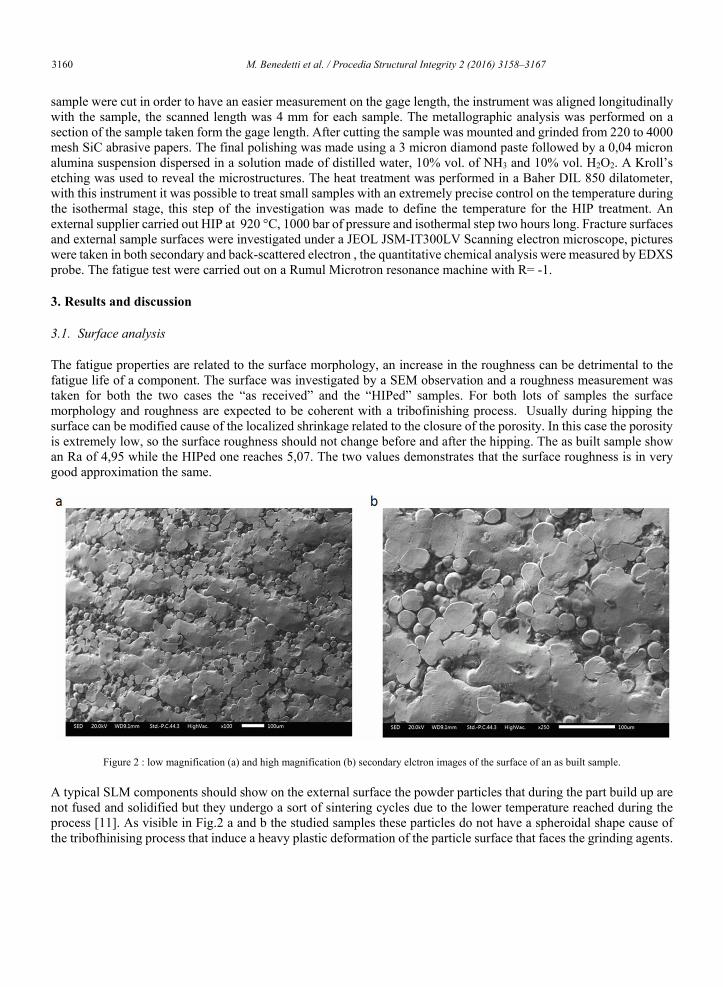
The fatigue properties are related to the surface morphology, an increase in the roughness can be detrimental to the fatigue life of a component. The surface was investigated by a SEM observation and a roughness measurement was taken for both the two cases the “as received” and the “HIPed” samples. For both lots of samples the surface morphology and roughness are expected to be coherent with a tribofinishing process. Usually during hipping the surface can be modified cause of the localized shrinkage related to the closure of the porosity. In this case the porosity is extremely low, so the surface roughness should not change before and after the hipping. The as built sample show an Ra of 4,95 while the HIPed one reaches 5,07. The two values demonstrates that the surface roughness is in very good approximation the same.
Figure 2 : low magnification (a) and high magnification (b) secondary elctron images of the surface of an as built sample.
A typical SLM components should show on the external surface the powder particles that during the part build up are not fused and solidified but they undergo a sort of sintering cycles due to the lower temperature reached during the process [11]. As visible in Fig.2 a and b the studied samples these particles do not have a spheroidal shape cause of the tribofhinising process that induce a heavy plastic deformation of the particle surface that faces the grinding agents.
4 M.Benedetti et al./ Structural Integrity Procedia 00 (2016) 000–000
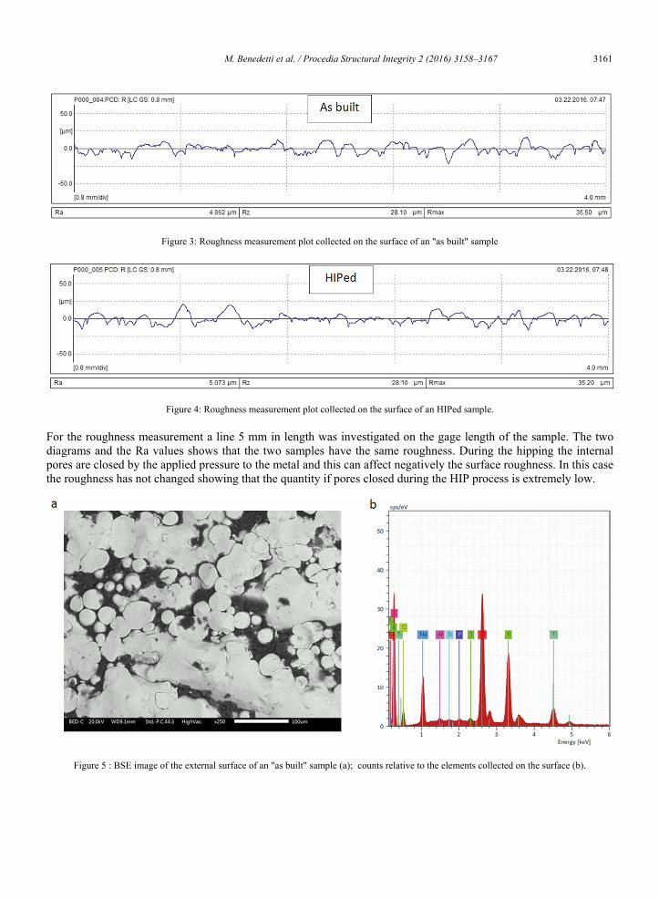
Figure 3: Roughness measurement plot collected on the surface of an "as built" sample
Figure 4: Roughness measurement plot collected on the surface of an HIPed sample.
For the roughness measurement a line 5 mm in length was investigated on the gage length of the sample. The two diagrams and the Ra values shows that the two samples have the same roughness. During the hipping the internal pores are closed by the applied pressure to the metal and this can affect negatively the surface roughness. In this case the roughness has not changed showing that the quantity if pores closed during the HIP process is extremely low.
Figure 5 : BSE image of the external surface of an "as built" sample (a); counts relative to the elements collected on the surface (b).
M. Benedetti et al. / Procedia Structural Integrity 2 (2016) 3158–3167 3161 M.Benedetti et al./ Structural Integrity Procedia 00 (2016) 000–000 3
sample were cut in order to have an easier measurement on the gage length, the instrument was aligned longitudinally with the sample, the scanned length was 4 mm for each sample. The metallographic analysis was performed on a section of the sample taken form the gage length. After cutting the sample was mounted and grinded from 220 to 4000 mesh SiC abrasive papers. The final polishing was made using a 3 micron diamond paste followed by a 0,04 micron alumina suspension dispersed in a solution made of distilled water, 10% vol. of NH3 and 10% vol. H2O2. A Kroll’s etching was used to reveal the microstructures. The heat treatment was performed in a Baher DIL 850 dilatometer, with this instrument it was possible to treat small samples with an extremely precise control on the temperature during the isothermal stage, this step of the investigation was made to define the temperature for the HIP treatment. An external supplier carried out HIP at 920 °C, 1000 bar of pressure and isothermal step two hours long. Fracture surfaces and external sample surfaces were investigated under a JEOL JSM-IT300LV Scanning electron microscope, pictures were taken in both secondary and back-scattered electron , the quantitative chemical analysis were measured by EDXS probe. The fatigue test were carried out on a Rumul Microtron resonance machine with R= -1.
3. Results and discussion
3.1. Surface analysis
The fatigue properties are related to the surface morphology, an increase in the roughness can be detrimental to the fatigue life of a component. The surface was investigated by a SEM observation and a roughness measurement was taken for both the two cases the “as received” and the “HIPed” samples. For both lots of samples the surface morphology and roughness are expected to be coherent with a tribofinishing process. Usually during hipping the surface can be modified cause of the localized shrinkage related to the closure of the porosity. In this case the porosity is extremely low, so the surface roughness should not change before and after the hipping. The as built sample show an Ra of 4,95 while the HIPed one reaches 5,07. The two values demonstrates that the surface roughness is in very good approximation the same.
Figure 2 : low magnification (a) and high magnification (b) secondary elctron images of the surface of an as built sample.
A typical SLM components should show on the external surface the powder particles that during the part build up are not fused and solidified but they undergo a sort of sintering cycles due to the lower temperature reached during the process [11]. As visible in Fig.2 a and b the studied samples these particles do not have a spheroidal shape cause of the tribofhinising process that induce a heavy plastic deformation of the particle surface that faces the grinding agents.
4 M.Benedetti et al./ Structural Integrity Procedia 00 (2016) 000–000
Figure 3: Roughness measurement plot collected on the surface of an "as built" sample
Figure 4: Roughness measurement plot collected on the surface of an HIPed sample.
For the roughness measurement a line 5 mm in length was investigated on the gage length of the sample. The two diagrams and the Ra values shows that the two samples have the same roughness. During the hipping the internal pores are closed by the applied pressure to the metal and this can affect negatively the surface roughness. In this case the roughness has not changed showing that the quantity if pores closed during the HIP process is extremely low.
Figure 5 : BSE image of the external surface of an "as built" sample (a); counts relative to the elements collected on the surface (b).

3162 M. Benedetti et al. / Procedia Structural Integrity 2 (2016) 3158–3167 M.Benedetti et al./ Structural Integrity Procedia 00 (2016) 000–000 5
Table 1 : quantitative analysys of the elements collected on the surface of the “as built” sample.
3.2. Microstructure, thermal treatment and microhardness
The microstructure was revealed by an etching with Kroll’s reagent. Fig.6a and Fig.6b illustrate the microstructure of the sample after the stress relief, in the “as built” condition. The microstructure is a very fine acicular α’ martensite typical of SLM products [12]. The high cooling rate that occurs in the SLM process during solidification creates a martensite microstructure, the following thermal process that involves the fusion and solidification of the upper layers can affect the microstructure of the previous ones but anyway it is not sufficient to apply a stress relief or a microstructural modification.
Figure 6: microstructure of the SLM sample after the stress relief treatment, 200X (a) and 500X (b).
After the sample building a final heat treatment is necessary to modify the microstructure or at least to decrease the residual stresses. From the first lot of samples some specimen were obtained and subjected to three different heat treatment inside a Baehr DIL 805 dilatometer. Samples are heated with a heating rate of 5K/min and cooled down to room temperature with a cooling rate of 5 K/min. For this alloy the Beta transus temperature is around 980°C, the temperatures for the isothermal stage of the treatment were chosen above this limit, 900°C, 920°C and 950°C . The treatment is equivalent to an annealing , the starting α’ martensite formed upon cooling is a metastable phase, as soon as the temperature is increased, avoiding to pass the beta transus temperature, the α phase starts to form. The metallographic analysis carried out on the samples after the heat treatment shows sensible differences respect to the
Element At. No. Counts Mass. Norm. [%] Atom. [%] Sodium 10 13173 20,10 29,46 Chlorine 17 55328 35,70 33,93 Potassium 19 35231 10,60 25,05 Titanium 22 9199 4,78 9,22 Sulfur 16 867 0,19 0,55 Phosphorus 15 595 0,15 0,43 Silicon 14 441 0,10 0,33 Aluminium 13 919 0,30 1,02 Sum 36,46 100,00
6 M.Benedetti et al./ Structural Integrity Procedia 00 (2016) 000–000
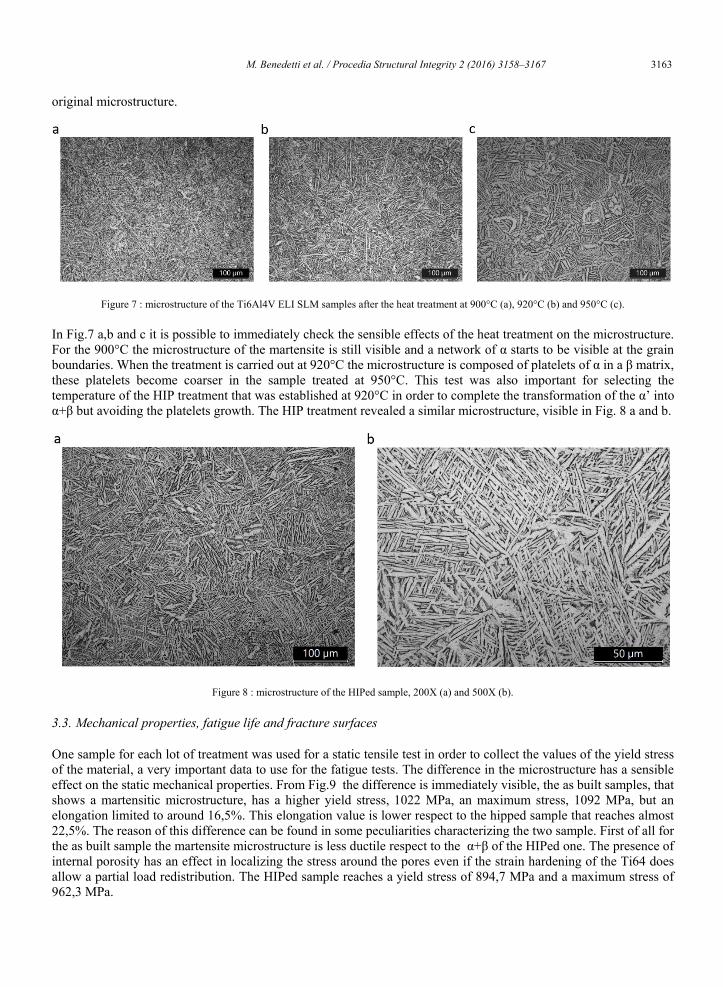
original microstructure.
Figure 7 : microstructure of the Ti6Al4V ELI SLM samples after the heat treatment at 900°C (a), 920°C (b) and 950°C (c).
In Fig.7 a,b and c it is possible to immediately check the sensible effects of the heat treatment on the microstructure. For the 900°C the microstructure of the martensite is still visible and a network of α starts to be visible at the grain boundaries. When the treatment is carried out at 920°C the microstructure is composed of platelets of α in a β matrix, these platelets become coarser in the sample treated at 950°C. This test was also important for selecting the temperature of the HIP treatment that was established at 920°C in order to complete the transformation of the α’ into α+β but avoiding the platelets growth. The HIP treatment revealed a similar microstructure, visible in Fig. 8 a and b.
Figure 8 : microstructure of the HIPed sample, 200X (a) and 500X (b).
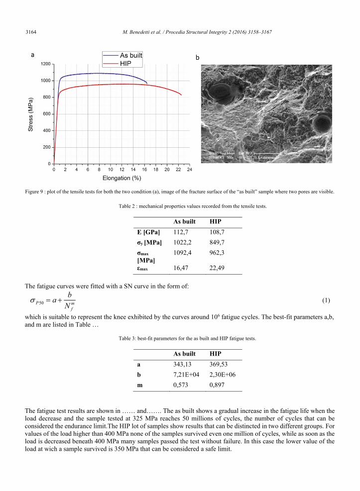
3.3. Mechanical properties, fatigue life and fracture surfaces
One sample for each lot of treatment was used for a static tensile test in order to collect the values of the yield stress of the material, a very important data to use for the fatigue tests. The difference in the microstructure has a sensible effect on the static mechanical properties. From Fig.9 the difference is immediately visible, the as built samples, that shows a martensitic microstructure, has a higher yield stress, 1022 MPa, an maximum stress, 1092 MPa, but an elongation limited to around 16,5%. This elongation value is lower respect to the hipped sample that reaches almost 22,5%. The reason of this difference can be found in some peculiarities characterizing the two sample. First of all for the as built sample the martensite microstructure is less ductile respect to the α+β of the HIPed one. The presence of internal porosity has an effect in localizing the stress around the pores even if the strain hardening of the Ti64 does allow a partial load redistribution. The HIPed sample reaches a yield stress of 894,7 MPa and a maximum stress of 962,3 MPa.
M. Benedetti et al. / Procedia Structural Integrity 2 (2016) 3158–3167 3163 M.Benedetti et al./ Structural Integrity Procedia 00 (2016) 000–000 5
Table 1 : quantitative analysys of the elements collected on the surface of the “as built” sample.
3.2. Microstructure, thermal treatment and microhardness
The microstructure was revealed by an etching with Kroll’s reagent. Fig.6a and Fig.6b illustrate the microstructure of the sample after the stress relief, in the “as built” condition. The microstructure is a very fine acicular α’ martensite typical of SLM products [12]. The high cooling rate that occurs in the SLM process during solidification creates a martensite microstructure, the following thermal process that involves the fusion and solidification of the upper layers can affect the microstructure of the previous ones but anyway it is not sufficient to apply a stress relief or a microstructural modification.
Figure 6: microstructure of the SLM sample after the stress relief treatment, 200X (a) and 500X (b).
After the sample building a final heat treatment is necessary to modify the microstructure or at least to decrease the residual stresses. From the first lot of samples some specimen were obtained and subjected to three different heat treatment inside a Baehr DIL 805 dilatometer. Samples are heated with a heating rate of 5K/min and cooled down to room temperature with a cooling rate of 5 K/min. For this alloy the Beta transus temperature is around 980°C, the temperatures for the isothermal stage of the treatment were chosen above this limit, 900°C, 920°C and 950°C . The treatment is equivalent to an annealing , the starting α’ martensite formed upon cooling is a metastable phase, as soon as the temperature is increased, avoiding to pass the beta transus temperature, the α phase starts to form. The metallographic analysis carried out on the samples after the heat treatment shows sensible differences respect to the
Element At. No. Counts Mass. Norm. [%] Atom. [%] Sodium 10 13173 20,10 29,46 Chlorine 17 55328 35,70 33,93 Potassium 19 35231 10,60 25,05 Titanium 22 9199 4,78 9,22 Sulfur 16 867 0,19 0,55 Phosphorus 15 595 0,15 0,43 Silicon 14 441 0,10 0,33 Aluminium 13 919 0,30 1,02 Sum 36,46 100,00
6 M.Benedetti et al./ Structural Integrity Procedia 00 (2016) 000–000
original microstructure.
Figure 7 : microstructure of the Ti6Al4V ELI SLM samples after the heat treatment at 900°C (a), 920°C (b) and 950°C (c).
In Fig.7 a,b and c it is possible to immediately check the sensible effects of the heat treatment on the microstructure. For the 900°C the microstructure of the martensite is still visible and a network of α starts to be visible at the grain boundaries. When the treatment is carried out at 920°C the microstructure is composed of platelets of α in a β matrix, these platelets become coarser in the sample treated at 950°C. This test was also important for selecting the temperature of the HIP treatment that was established at 920°C in order to complete the transformation of the α’ into α+β but avoiding the platelets growth. The HIP treatment revealed a similar microstructure, visible in Fig. 8 a and b.
Figure 8 : microstructure of the HIPed sample, 200X (a) and 500X (b).
3.3. Mechanical properties, fatigue life and fracture surfaces
One sample for each lot of treatment was used for a static tensile test in order to collect the values of the yield stress of the material, a very important data to use for the fatigue tests. The difference in the microstructure has a sensible effect on the static mechanical properties. From Fig.9 the difference is immediately visible, the as built samples, that shows a martensitic microstructure, has a higher yield stress, 1022 MPa, an maximum stress, 1092 MPa, but an elongation limited to around 16,5%. This elongation value is lower respect to the hipped sample that reaches almost 22,5%. The reason of this difference can be found in some peculiarities characterizing the two sample. First of all for the as built sample the martensite microstructure is less ductile respect to the α+β of the HIPed one. The presence of internal porosity has an effect in localizing the stress around the pores even if the strain hardening of the Ti64 does allow a partial load redistribution. The HIPed sample reaches a yield stress of 894,7 MPa and a maximum stress of 962,3 MPa.
3164 M. Benedetti et al. / Procedia Structural Integrity 2 (2016) 3158–3167 M.Benedetti et al./ Structural Integrity Procedia 00 (2016) 000–000 7
Figure 9 : plot of the tensile tests for both the two condition (a), image of the fracture surface of the “as built” sample where two pores are visible.
Table 2 : mechanical properties values recorded from the tensile tests.
As built HIP E [GPa] 112,7 108,7 σy [MPa] 1022,2 849,7 σmax [MPa]
1092,4 962,3
εmax 16,47 22,49 The fatigue curves were fitted with a SN curve in the form of:
P50 a bN f
m (1)
which is suitable to represent the knee exhibited by the curves around 106 fatigue cycles. The best-fit parameters a,b, and m are listed in Table …
Table 3: best-fit parameters for the as built and HIP fatigue tests.
As built HIP a 343,13 369,53 b 7,21E+04 2,30E+06 m 0,573 0,897
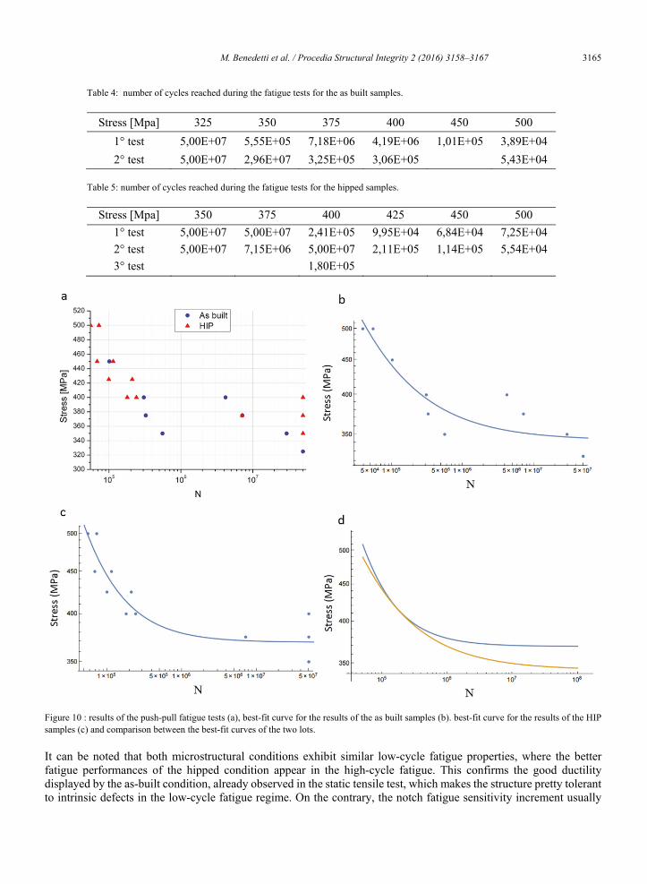
The fatigue test results are shown in …… and……. The as built shows a gradual increase in the fatigue life when the load decrease and the sample tested at 325 MPa reaches 50 millions of cycles, the number of cycles that can be considered the endurance limit.The HIP lot of samples show results that can be distincted in two different groups. For values of the load higher than 400 MPa none of the samples survived even one million of cycles, while as soon as the load is decreased beneath 400 MPa many samples passed the test without failure. In this case the lower value of the load at wich a sample survived is 350 MPa that can be considered a safe limit.
8 M.Benedetti et al./ Structural Integrity Procedia 00 (2016) 000–000
Table 4: number of cycles reached during the fatigue tests for the as built samples.
Stress [Mpa] 325 350 375 400 450 500 1° test 5,00E+07 5,55E+05 7,18E+06 4,19E+06 1,01E+05 3,89E+04 2° test 5,00E+07 2,96E+07 3,25E+05 3,06E+05 5,43E+04
Table 5: number of cycles reached during the fatigue tests for the hipped samples.
Stress [Mpa] 350 375 400 425 450 500 1° test 5,00E+07 5,00E+07 2,41E+05 9,95E+04 6,84E+04 7,25E+04 2° test 5,00E+07 7,15E+06 5,00E+07 2,11E+05 1,14E+05 5,54E+04 3° test 1,80E+05
Figure 10 : results of the push-pull fatigue tests (a), best-fit curve for the results of the as built samples (b). best-fit curve for the results of the HIP samples (c) and comparison between the best-fit curves of the two lots.
It can be noted that both microstructural conditions exhibit similar low-cycle fatigue properties, where the better fatigue performances of the hipped condition appear in the high-cycle fatigue. This confirms the good ductility displayed by the as-built condition, already observed in the static tensile test, which makes the structure pretty tolerant to intrinsic defects in the low-cycle fatigue regime. On the contrary, the notch fatigue sensitivity increment usually
M. Benedetti et al. / Procedia Structural Integrity 2 (2016) 3158–3167 3165 M.Benedetti et al./ Structural Integrity Procedia 00 (2016) 000–000 7
Figure 9 : plot of the tensile tests for both the two condition (a), image of the fracture surface of the “as built” sample where two pores are visible.
Table 2 : mechanical properties values recorded from the tensile tests.
As built HIP E [GPa] 112,7 108,7 σy [MPa] 1022,2 849,7 σmax [MPa]
1092,4 962,3
εmax 16,47 22,49 The fatigue curves were fitted with a SN curve in the form of:
P50 a bN f
m (1)
which is suitable to represent the knee exhibited by the curves around 106 fatigue cycles. The best-fit parameters a,b, and m are listed in Table …
Table 3: best-fit parameters for the as built and HIP fatigue tests.
As built HIP a 343,13 369,53 b 7,21E+04 2,30E+06 m 0,573 0,897
The fatigue test results are shown in …… and……. The as built shows a gradual increase in the fatigue life when the load decrease and the sample tested at 325 MPa reaches 50 millions of cycles, the number of cycles that can be considered the endurance limit.The HIP lot of samples show results that can be distincted in two different groups. For values of the load higher than 400 MPa none of the samples survived even one million of cycles, while as soon as the load is decreased beneath 400 MPa many samples passed the test without failure. In this case the lower value of the load at wich a sample survived is 350 MPa that can be considered a safe limit.
8 M.Benedetti et al./ Structural Integrity Procedia 00 (2016) 000–000
Table 4: number of cycles reached during the fatigue tests for the as built samples.
Stress [Mpa] 325 350 375 400 450 500 1° test 5,00E+07 5,55E+05 7,18E+06 4,19E+06 1,01E+05 3,89E+04 2° test 5,00E+07 2,96E+07 3,25E+05 3,06E+05 5,43E+04
Table 5: number of cycles reached during the fatigue tests for the hipped samples.
Stress [Mpa] 350 375 400 425 450 500 1° test 5,00E+07 5,00E+07 2,41E+05 9,95E+04 6,84E+04 7,25E+04 2° test 5,00E+07 7,15E+06 5,00E+07 2,11E+05 1,14E+05 5,54E+04 3° test 1,80E+05
Figure 10 : results of the push-pull fatigue tests (a), best-fit curve for the results of the as built samples (b). best-fit curve for the results of the HIP samples (c) and comparison between the best-fit curves of the two lots.
It can be noted that both microstructural conditions exhibit similar low-cycle fatigue properties, where the better fatigue performances of the hipped condition appear in the high-cycle fatigue. This confirms the good ductility displayed by the as-built condition, already observed in the static tensile test, which makes the structure pretty tolerant to intrinsic defects in the low-cycle fatigue regime. On the contrary, the notch fatigue sensitivity increment usually
3166 M. Benedetti et al. / Procedia Structural Integrity 2 (2016) 3158–3167 M.Benedetti et al./ Structural Integrity Procedia 00 (2016) 000–000 9
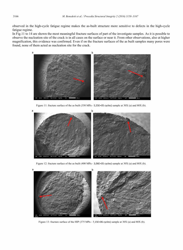
observed in the high-cycle fatigue regime makes the as-built structure more sensitive to defects in the high-cycle fatigue regime. In Fig.11 to 14 are shown the most meaningful fracture surfaces of part of the investigate samples. As it is possible to observe the nucleation site of the crack is in all cases on the surface or near it. From other observations, also at higher magnification, this evidence was confirmed. Even if on the fracture surfaces of the as built samples many pores were found, none of them acted as nucleation site for the crack.
Figure 11: fracture surface of the as built (350 MPa - 5,55E+05 cycles) sample at 30X (a) and 80X (b).
Figure 12: fracture surface of the as built (400 MPa - 3,06E+05 cycles) sample at 30X (a) and 80X (b).
Figure 13: fracture surface of the HIP (375 MPa - 7,15E+06 cycles) sample at 30X (a) and 80X (b).
10 M.Benedetti et al./ Structural Integrity Procedia 00 (2016) 000–000
4. Conclusion The as built samples and the HIPed samples showed very different microstructures. This difference is not so evident on the hardness values but has a significant effect on the static mechanical properties, the martensite microstructure allows the as built samples to reach higher values of the yield and maximum stress during the tensile test while the higher ductility of the α+β microstructure helps the HIPed sample to reach a higher elongation and a good strain hardening. This improved strain hardening shown by the HIP samples may also play an important role in the fatigue tests. The crack propagation can be delayed by the redistribution of the stress due to the plastic deformation in front of the crack. Another important factor affecting the fatigue tests is the roughness, which greatly influences the fatigue crack nucleation and in this case the Ra values of the two lots of samples are similar due to the tribofinishing process applied to all samples. The HIP process had no effect on the roughness also because the internal porosity to be closed was limited in quantity and size. With the same roughness there is one variable less to understand the results of the fatigue tests. The as built samples results are affected by a wide scatter, so even if the crack nucleation was observed to have always started on the surface, the pores network can act as a preferential way for the crack to propagate and bring to the sample failure. It is possible to say that the HIP process improved the high-cycle fatigue resistance of the SLM Ti64 samples and for future investigation an even lower value of the surface roughness should be tested for further improvement.
References
Frazier, W. E., 2014. Metal Additive Manufacturing: A Review. Journal of Materials Engineering and Performance 23(6), 1917–28. Sieniawski, J., Ziaja, W., Kubiak, K., Motyka, M., 2013. Titanium Alloys - Advances in Properties Control. Titanium Alloys - Advances in
Properties Control, 70–80. Lewis, G.. 2013. Properties of Open-Cell Porous Metals and Alloys for Orthopaedic Applications. Journal of Materials Science, Materials in
Medicine 24(10), 2293–2325. Murr, L E et al. 2010. Next-Generation Biomedical Implants Using Additive Manufacturing of Complex, Cellular and Functional Mesh Arrays.
Philosophical transactions. Series A, Mathematical, physical, and engineering sciences 368(1917), 1999–2032. Murr, L. E. et al. 2009. Microstructure and Mechanical Behavior of Ti-6Al-4V Produced by Rapid-Layer Manufacturing, for Biomedical
Applications. Journal of the Mechanical Behavior of Biomedical Materials 2(1), 20–32. Pederson, R., (Department of Applied Physics and Mechanical Engineering Division of Engineering Materials). 2002. Microstructure and Phase
Transformation of Ti-6Al-4V. , 27–30. Spierings, A.B., Starr, T.L., Wegener, K., 2013. Fatigue Performance of Additive Manufactured Metallic Parts. Rapid Prototyping Journal 19(2),
88–94. Sterling, A., Shamsaei, N., Torries, B., Thompson, S.M., 2015. Fatigue Behaviour of Additively Manufactured Ti-6Al-4V. Procedia Engineering
133, 576–89. Strano, G., Hao, L., Everson, R.M., Evans, K. M., 2013. Journal of Materials Processing Technology Surface Roughness Analysis , Modelling and
Prediction in Selective Laser Melting. Journal of Materials Processing Tech. 213(4), 589–97. Vrancken, B., Thijs, L., Kruth, J.-P., Van Humbeeck, J., 2012. Heat Treatment of Ti6Al4V Produced by Selective Laser Melting : Microstructure
and Mechanical Properties. Journal of Alloys and Compounds 541, 177–85. . Kaufui V. W., Hernandez, A., 2012. A Review of Additive Manufacturing. ISRN Mechanical Engineering 2012, 1–10. Yavari, S. A., 2013. Fatigue Behavior of Porous Biomaterials Manufactured Using Selective Laser Melting. Materials S. & E. C 33(8), 4849–58.
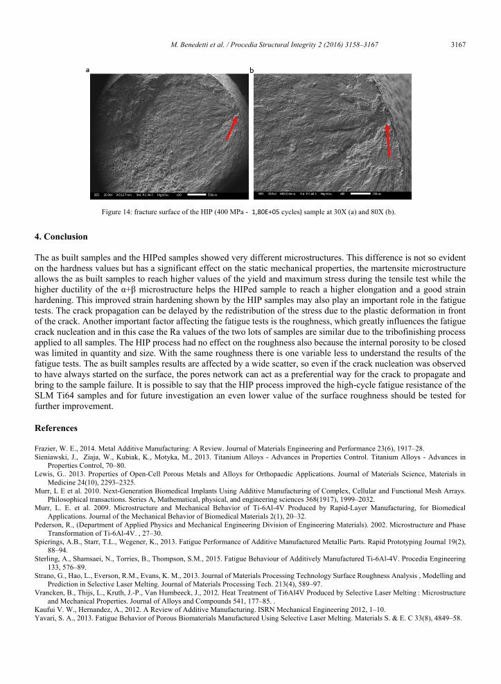
Figure 14: fracture surface of the HIP (400 MPa - 1,80E+05 cycles) sample at 30X (a) and 80X (b).
M. Benedetti et al. / Procedia Structural Integrity 2 (2016) 3158–3167 3167 M.Benedetti et al./ Structural Integrity Procedia 00 (2016) 000–000 9
observed in the high-cycle fatigue regime makes the as-built structure more sensitive to defects in the high-cycle fatigue regime. In Fig.11 to 14 are shown the most meaningful fracture surfaces of part of the investigate samples. As it is possible to observe the nucleation site of the crack is in all cases on the surface or near it. From other observations, also at higher magnification, this evidence was confirmed. Even if on the fracture surfaces of the as built samples many pores were found, none of them acted as nucleation site for the crack.
Figure 11: fracture surface of the as built (350 MPa - 5,55E+05 cycles) sample at 30X (a) and 80X (b).
Figure 12: fracture surface of the as built (400 MPa - 3,06E+05 cycles) sample at 30X (a) and 80X (b).
Figure 13: fracture surface of the HIP (375 MPa - 7,15E+06 cycles) sample at 30X (a) and 80X (b).
10 M.Benedetti et al./ Structural Integrity Procedia 00 (2016) 000–000
4. Conclusion The as built samples and the HIPed samples showed very different microstructures. This difference is not so evident on the hardness values but has a significant effect on the static mechanical properties, the martensite microstructure allows the as built samples to reach higher values of the yield and maximum stress during the tensile test while the higher ductility of the α+β microstructure helps the HIPed sample to reach a higher elongation and a good strain hardening. This improved strain hardening shown by the HIP samples may also play an important role in the fatigue tests. The crack propagation can be delayed by the redistribution of the stress due to the plastic deformation in front of the crack. Another important factor affecting the fatigue tests is the roughness, which greatly influences the fatigue crack nucleation and in this case the Ra values of the two lots of samples are similar due to the tribofinishing process applied to all samples. The HIP process had no effect on the roughness also because the internal porosity to be closed was limited in quantity and size. With the same roughness there is one variable less to understand the results of the fatigue tests. The as built samples results are affected by a wide scatter, so even if the crack nucleation was observed to have always started on the surface, the pores network can act as a preferential way for the crack to propagate and bring to the sample failure. It is possible to say that the HIP process improved the high-cycle fatigue resistance of the SLM Ti64 samples and for future investigation an even lower value of the surface roughness should be tested for further improvement.
References
Frazier, W. E., 2014. Metal Additive Manufacturing: A Review. Journal of Materials Engineering and Performance 23(6), 1917–28. Sieniawski, J., Ziaja, W., Kubiak, K., Motyka, M., 2013. Titanium Alloys - Advances in Properties Control. Titanium Alloys - Advances in
Properties Control, 70–80. Lewis, G.. 2013. Properties of Open-Cell Porous Metals and Alloys for Orthopaedic Applications. Journal of Materials Science, Materials in
Medicine 24(10), 2293–2325. Murr, L E et al. 2010. Next-Generation Biomedical Implants Using Additive Manufacturing of Complex, Cellular and Functional Mesh Arrays.
Philosophical transactions. Series A, Mathematical, physical, and engineering sciences 368(1917), 1999–2032. Murr, L. E. et al. 2009. Microstructure and Mechanical Behavior of Ti-6Al-4V Produced by Rapid-Layer Manufacturing, for Biomedical
Applications. Journal of the Mechanical Behavior of Biomedical Materials 2(1), 20–32. Pederson, R., (Department of Applied Physics and Mechanical Engineering Division of Engineering Materials). 2002. Microstructure and Phase
Transformation of Ti-6Al-4V. , 27–30. Spierings, A.B., Starr, T.L., Wegener, K., 2013. Fatigue Performance of Additive Manufactured Metallic Parts. Rapid Prototyping Journal 19(2),
88–94. Sterling, A., Shamsaei, N., Torries, B., Thompson, S.M., 2015. Fatigue Behaviour of Additively Manufactured Ti-6Al-4V. Procedia Engineering
133, 576–89. Strano, G., Hao, L., Everson, R.M., Evans, K. M., 2013. Journal of Materials Processing Technology Surface Roughness Analysis , Modelling and
Prediction in Selective Laser Melting. Journal of Materials Processing Tech. 213(4), 589–97. Vrancken, B., Thijs, L., Kruth, J.-P., Van Humbeeck, J., 2012. Heat Treatment of Ti6Al4V Produced by Selective Laser Melting : Microstructure
and Mechanical Properties. Journal of Alloys and Compounds 541, 177–85. . Kaufui V. W., Hernandez, A., 2012. A Review of Additive Manufacturing. ISRN Mechanical Engineering 2012, 1–10. Yavari, S. A., 2013. Fatigue Behavior of Porous Biomaterials Manufactured Using Selective Laser Melting. Materials S. & E. C 33(8), 4849–58.
Figure 14: fracture surface of the HIP (400 MPa - 1,80E+05 cycles) sample at 30X (a) and 80X (b).