fatigue life assessment by haagensen
DESCRIPTION
Fatigue life predictions analysis should be performed according to standards in order to avoid uncertainties regarding assumptions for loads and component capacity.TRANSCRIPT

1
Fatigue design of welded structures - Norsok and Eurocode 3 2011 P J Haagensen 1
Professor P J Haagensen
Norges teknisk-naturvitenskapelige universitet
Fakultet for ingeniørvitenskap og teknologi Institutt for konstruksjonsteknikk
Trondheim
Utmattingsberegninger for stålkonstruksjoner
ihht NORSOK og Eurokode 3
Fatigue life assessment
Tirsdag 13 desember 2011
Fatigue design of welded structures - Norsok and Eurocode 3 2011 P J Haagensen 2
Approaches to fatigue life estimation
1. Nominal stress
2. Hot spot stress
3. Notch stress
4. Fracture mechanichs
Loads and stress calculations
Damage accumulation
Comparisons of standards
Fatigue life assessment
•
Topics

2
Fatigue design of welded structures - Norsok and Eurocode 3 2011 P J Haagensen 3
Fatigue life assessment.
Fatigue life predictions analysis should be
performed according to standards in order to avoid
uncertainties regarding assumptions for loads and
component capacity.
Fatigue design of welded structures - Norsok and Eurocode 3 2011 P J Haagensen 4
Fatigue life assessment approaches
- S-N curves, nominal stress
- S-N curves, hot spot stress
- S-N curves, notch stress
- Crack growth curves
(da/dN - K diagram

3
Fatigue design of welded structures - Norsok and Eurocode 3 2011 P J Haagensen 5
Loading data – load spectra
Cumulative load spectra obtained by stress range counting
(rainflow) is converted to histogram to give stress ranges Sr vs.
number of cycles ni per stress interval
Fatigue design of welded structures - Norsok and Eurocode 3 2011 P J Haagensen 6
Narrow band vs. broad band load time
histories:
Frequency
Narrow band PSD
Time
Stress
Stress
Time
Broad band
Frequency
PSD
PSD = Power Spectrum Density

4
Fatigue design of welded structures - Norsok and Eurocode 3 2011 P J Haagensen 7
Fatigue damage
accumulation
Damage at stress level Sri :
i
ii
N
nd
0.11
k
i i
i
N
nD
Cumulative damage at fracture
(Miner-Palmgren rule:
If damage due to loads in spectrum = DT (during time T )
then:
Fatigue life L = T/DT
i
k
Log n, Log N
Stress range bin #
Number of stress range
occurrences, ni
Experimental
S-N curve
Number of cycles
to failure, Nfi
Design
Fatigue design of welded structures - Norsok and Eurocode 3 2011 P J Haagensen 8
Uncertainties in calculated fatigue life are
caused by: 1. Uncertainties in load spectra
2. Uncertainties in S-N curves - extrapolation
3. Uncertainties in Miner-Palmgren damage
summation rule (sequence effects)
Fatigue tests with representative load–time histories show
that the damage sum
at failure varies typically in the range 0.1 < D < 10
k
i
i=1 i
nD =
N
Some tests indicate that D decreases with increasing
irregularity, i.e. more than one peak in the power density
spectrum (PSD)
IIW design guidance recommends D ≤ 0.5 instead of 1.0 at failure
DNV: D ≤ where is the usage factor. 0.5 < <0.1 depending on
inspectability and consequences of failure.

5
Fatigue design of welded structures - Norsok and Eurocode 3 2011 P J Haagensen 9
Sequence effects gives variations in Miner-
Palmgren damage sum
Cycles
Cra
ck length
Overloads in tension
blunt the crack tip and
introduce compressive
stresses that slow
down crack growth
Fatigue design of welded structures - Norsok and Eurocode 3 2011 P J Haagensen 10
Uncertainties in extrapolation of S-N curves A major source of uncertainty is related to the extrapolation of
the S-N curve below the constant amplitude fatigue limit. In
most current codes, e.g. Norsok, DNV and IIW the knee point
is now at N =107 cycles. However, an increasing amount of test
data indicate that the knee point should be at N =108, or a
straight line extrapolation should be used.
Fisher, 1993 Dahle, 1994

6
Fatigue design of welded structures - Norsok and Eurocode 3 2011 P J Haagensen 11
Extrapolation of S-N curves
New test data indicate that the knee point should be at N =108, or a
straight line extrapolation should be used.
Sonsino, Maddox & Haagensen
IIW 2004
EXXON data, OMAE 2003
107 108
107
Fatigue design of welded structures - Norsok and Eurocode 3 2011 P J Haagensen 12
Fatigue life calculation – nominal stress method
1. Choose weld class
2. Calculate nominal stress range
3. Correct stress range for thickness effect and ?
3. Determine cycles to failure from S-N curve
4. Use Miner rule to calculate damage and life
misalignment

7
Fatigue design of welded structures - Norsok and Eurocode 3 2011 P J Haagensen 13
What loads and stresses to consider?
All types of fluctuating load acting on the component and the
resulting stresses at potential sites for fatigue have to be
considered. Stresses or stress intensity factors then have to be
determined according to the fatigue assessment procedure
applied.
The actions originate from live loads, dead weights, snow, wind,
waves, pressure, accelerations, dynamic response etc. Actions
due to transient temperature changes should be considered.
Improper knowledge of fatigue actions is one of the major sources
of fatigue problems.
Tensile residual stresses due to welding decrease the fatigue
resistance, however, the influence of residual weld stresses is
already included in the fatigue resistance data given in S-N curves
Fatigue life calculation – nominal stress method
Fatigue design of welded structures - Norsok and Eurocode 3 2011 P J Haagensen 14
Separation of stress components
The membrane stress mem is equal to the average stress calculated
through the thickness of the plate. It is constant through the thickness.
The shell bending stress bend is linearly distributed through the
thickness of the plate. It is found by drawing a straight line through the
point O where the membrane stress intersects the mid-plane of the plate.
The gradient of the shell bending stress is chosen such that the
remaining non-linearly distributed component is in equilibrium.
The non-linear stress peak nlp is the remaining component of the stress.

8
Fatigue design of welded structures - Norsok and Eurocode 3 2011 P J Haagensen 15
Nominal stress is the stress calculated in the sectional area
under consideration, disregarding the local stress raising effects
of the welded joint, but including the stress raising effects of the
macro-geometric shape of the component in the vicinity of the
joint, such as e.g. large cut-outs. Overall elastic behaviour is
assumed.
Nominal stress calculations
Fatigue design of welded structures - Norsok and Eurocode 3 2011 P J Haagensen 16
Effects of macrogeometric features of the component as well
as stress fields in the vicinity of concentrated loads must be
included in the nominal stress:
Nominal stress calculations
9
Fatigue design of welded structures - Norsok and Eurocode 3 2011 P J Haagensen 17
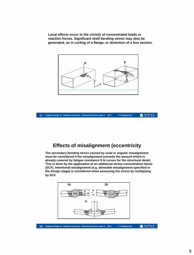
Local effects occur in the vicinity of concentrated loads or
reaction forces. Significant shell bending stress may also be
generated, as in curling of a flange, or distortion of a box section.
Fatigue design of welded structures - Norsok and Eurocode 3 2011 P J Haagensen 18
The secondary bending stress caused by axial or angular misalignment
must be considered if the misalignment exceeds the amount which is
already covered by fatigue resistance S-N curves for the structural detail.
This is done by the application of an additional stress concentration factor
(SCF). Intentional misalignment (e.g. allowable misalignment specified in
the design stage) is considered when assessing the stress by multiplying
by SCF.
Effects of misalignment (eccentricity

10
Fatigue design of welded structures - Norsok and Eurocode 3 2011 P J Haagensen 19
In other cases, finite element method (FEM) modelling may be used.
This is primarily the case in:
a) complicated statically over-determined (redundant) structures
b) structural components incorporating macro-geometric
discontinuities, for which no analytical solutions are available
Using FEM, meshing can be simple and coarse. However, care must
be taken to ensure that all stress raising effects of the structural
detail of the welded joint are excluded when calculating the
modified (local) nominal stress.
Calculation of nominal stress In simple components the nominal stress can be determined
using elementary theories of structural mechanics based on
linear-elastic behaviour.
Fatigue design of welded structures - Norsok and Eurocode 3 2011 P J Haagensen 20
• Misalignment, axial and angular
• Effects of stress relief
• Plate thickness, for t > 25 mm
• Effects of corrosion
• Temperature
• Effects of high and low stresses in the spectrum
Modification of basic S-N curves
The basic S-N curves may need to be modified for the following
influencing factors:
Material: Different S-N curves for steel, aluminium,
titanium

11
Fatigue design of welded structures - Norsok and Eurocode 3 2011 P J Haagensen 21
Butt welds: 0 = 0.1t (10% of plate thickness)
Effects of misalignment (DNV & Norsok 004)
In the test data on which the design cures are based, some axial
misaligment (eccentricity) 0 is included as follows:
The effect of axial misaligment for butt welds e0 is accounted for
by applying a stress concentration factor SCF:
where m is the measured eccentricity
m 03 δ -δSCF =1-
t
Fatigue design of welded structures - Norsok and Eurocode 3 2011 P J Haagensen 22
Cruciform joints
Axial misalignment included in S-N curves:
e0 = 0.5t (15% of plate thickness)
where
δ = (δm + δt) is the total eccentricity.
δ0 = 0.3t is misalignment inherent in the
S-N data for cruciform joints
ti = thickness of the considered plate
(i = 1, 2)
li = length of considered plate (i = 1, 2)
12
Fatigue design of welded structures - Norsok and Eurocode 3 2011 P J Haagensen 23
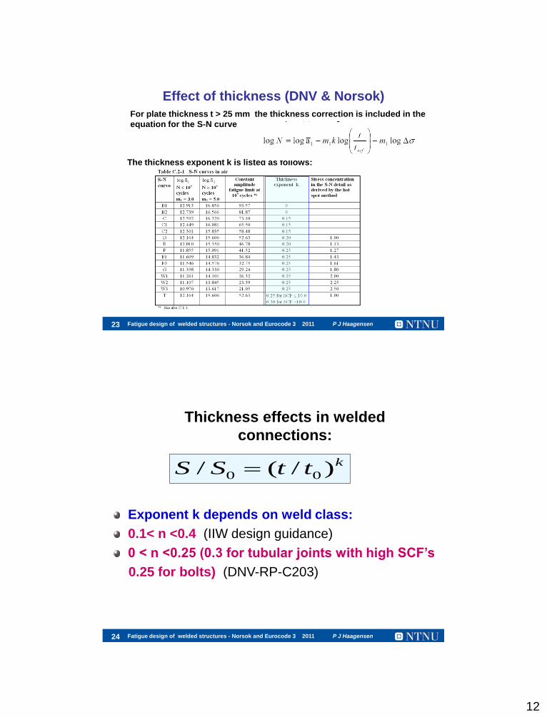
Effect of thickness (DNV & Norsok)
For plate thickness t > 25 mm the thickness correction is included in the
equation for the S-N curve
The thickness exponent k is listed as follows:
Fatigue design of welded structures - Norsok and Eurocode 3 2011 P J Haagensen 24
Thickness effects in welded
connections:
Exponent k depends on weld class:
0.1< n <0.4 (IIW design guidance)
0 < n <0.25 (0.3 for tubular joints with high SCF’s
0.25 for bolts) (DNV-RP-C203)
0 0/ ( / )kS S t t

13
Fatigue design of welded structures - Norsok and Eurocode 3 2011 P J Haagensen 25
Biaxial loading
1. Use the equivalent normal stress range is less than 10% of the equivalent
shear stress range, or if the damage sum due to shear stress range is
lower than 10% of that due to normal stress range, the effect of shear
stress may be neclected.
2. If the normal and shear stress vary simultaneously in phase, or if the
plane of maximum principal stress is not changed significantly, the
maximum principal stress range should be used.
IIW recommendations:
Fatigue design of welded structures - Norsok and Eurocode 3 2011 P J Haagensen 26
IIW verification procedures for combined normal and
shear stress using S-N curves

14
Fatigue design of welded structures - Norsok and Eurocode 3 2011 P J Haagensen 27
Norsok 004, NS 3472 and DNV RP-C203
Weld classes - 1 unwelded components
Fatigue design of welded structures - Norsok and Eurocode 3 2011 P J Haagensen 28
DNV RP-C203 Weld classes – example welded components

15
Fatigue design of welded structures - Norsok and Eurocode 3 2011 P J Haagensen 29
DNV RP-C203- Aug. 2005
S-N curves – welded structures in air
Fatigue design of welded structures - Norsok and Eurocode 3 2011 P J Haagensen 30
S-N curves – welded structures in air -details
DNV RP-C203- Aug. 2005

16
Fatigue design of welded structures - Norsok and Eurocode 3 2011 P J Haagensen 31
Fatigue life calculation – nominal stress method
1. Choose weld class
2. Calculate nominal stress range
3. Correct stress range for thickness effect and ?
3. Determine cycles to failure from S-N curve
4. Use Miner rule to calculate damage and life
misalignment
Fatigue design of welded structures - Norsok and Eurocode 3 2011 P J Haagensen 32
DNV RP-C203
S-N curve for high strength steel – unwelded material
YS > 500 Mpa, machined surface with Ra < 3.2 m
FAT 235 MPa
S-N curve

17
Fatigue design of welded structures - Norsok and Eurocode 3 2011 P J Haagensen 33
New S-N curve – small diameter umbilical pipes
in super duplex steel
Equations for S-N curve:
DNV RP-C203- Aug. 2010
Fatigue design of welded structures - Norsok and Eurocode 3 2011 P J Haagensen 34
The hot spot stress method
The hot spot stress is a local stress at the weld toe, taking
into account the overall geometry of the joint, except the
shape of the weld. It is therefore sometimes called the
structural or geometrical stress.
It is used when it is difficult to define a nominal stress, e.g. in
complicated plate structures.
Originally (in the 60’s), the stress was measured at a single spot. In
the AWS/API at a distance of 1/8” (3.2mm) from the weld toe, while
Haibach recommended 2mm.
In recent versions the stress at the weld toe is extrapolated from two or
three points near the weld toe. The method is included in DNV’s RP-C203,
also and IIW (International Institute of Welding)

18
Fatigue design of welded structures - Norsok and Eurocode 3 2011 P J Haagensen 35
Definition of the hot spot stress (DNV)
The hot spot stress is a linear extrapolation at distances 0.5t an 1.5t from
the weld toe.
In the IIW guidance the to points are at 0.4 and 1.0t. The stress at these
two points are obtained from FE analysis or from strain gauge
measurements.
Fatigue design of welded structures - Norsok and Eurocode 3 2011 P J Haagensen 36
Failure locations in welded joints
The structural hot spot stress method is normally applicable to surface cracks
only, but it is also possible to define a stress in a weld, e.g. by stress linearisation
over the weld throat or weld leg. Examples: Fillet weld subjected to local bending,
e.g. one-sided welds or welds around cover plates subjected to lateral loads
(Fricke et al.,2006)

19
Fatigue design of welded structures - Norsok and Eurocode 3 2011 P J Haagensen 37
Types of hot spot stress
The stresses obtained in FE analyses must include any
misalignments or by an appropriate stress concentration factor,
SCF.
Two or three types of hot spot stress are usully defined:
Fatigue design of welded structures - Norsok and Eurocode 3 2011 P J Haagensen 38
FE modeling - hot spot stress
The stresses obtained in FE analyses must include any
misalignments or an appropriate stress concentration factor, SCF.
Shell or solid elements are used in the FE meshing depending on
the shape and size of the structure

20
Fatigue design of welded structures - Norsok and Eurocode 3 2011 P J Haagensen 39 39 Utmatting - grunnlag Oslo, 8. nov. 2010 P J Haagensen
FE stress analysis – ship structure
Fatigue design of welded structures - Norsok and Eurocode 3 2011 P J Haagensen 40
Meshing rules and determination of hot spot stress
The IIW and DNV fatigue design rules give detailed advice regarding
meshing and determination of the hot spot stress
At the extrapolation procedures for structural hot spot
stress of type “b”, a wall thickness
correction exponent of n=0.1 shall be applied.
Reference points for different
types of meshing
Recommended meshing and extrapolation

21
Fatigue design of welded structures - Norsok and Eurocode 3 2011 P J Haagensen 41
Calculation of hot spot stress
Since the stresses obtained in FE analyses depend strongly on the
type of element and the mesh that are used, detailed guidance is
given in the design rules. The degree of bending influences life.
The DNV RP C-203 correction:
In IIW the FAT 90 curve is used for load carrying welds and FAT 100
for non-load carrying welds.
A single hot spot S-N curve is used by DNV (in air). This is the T-
curve = the D-curve = the FAT 90 curve. This is the S-N curve for a
“good” butt weld, welded from both sides.
Fatigue design of welded structures - Norsok and Eurocode 3 2011 P J Haagensen 42
The hot spot stress method – tubular joints
The hot spot stress method is used for tubular structures, and
parametric equations are given for stress concentration factors
(SCFs) for simple joint configurations. The hot spot stress to be
used when entering the S-N curve is given by:
HS nomSCF
An example of SCFs for a simple tubular joint:

22
Fatigue design of welded structures - Norsok and Eurocode 3 2011 P J Haagensen 43
Example of FE analysis
- out of plane loading of brace
Fatigue design of welded structures - Norsok and Eurocode 3 2011 P J Haagensen 44
S-N curves to use with the hot spot stress
In air: Use the T-curve (= the D-curve)

23
Fatigue design of welded structures - Norsok and Eurocode 3 2011 P J Haagensen 45
Effective notch stress method
The effective notch stress is the total stress at the root
of a notch, obtained assuming linear-elastic material
behaviour. For structural steels an effective notch root
radius of r = 1 mm in the FE analysis gives consistent
results. For fatigue assessment, the effective notch
stress is compared with a common fatigue resistance
curve.)The method is valid for plate thickness t> 5 mm
The FAT 225 (m=3) S-N curve is to be used in this
method. For t < 5 mm a radius o
The method is included in DNV’s revised RP-C203, April 2010
For t < 5 mm a radius of 0.05 has been proposed
(Sonsino 2002) with an S-N curve with FAT 630
Fatigue design of welded structures - Norsok and Eurocode 3 2011 P J Haagensen 46
Effective notch stress method
An effective notch radius of 1 mm is assumed in the FE
analysis
Main advantages:
Only one S-N curve is required, the FAT 225 curve.
Can be used to assess fatigue life for root cracks

24
Fatigue design of welded structures - Norsok and Eurocode 3 2011 P J Haagensen 47
Example of stress analysis of cover plate
which can fail from the weld toe or the root
Fatigue design of welded structures - Norsok and Eurocode 3 2011 P J Haagensen 48
Example from 2D FE analysis
50 mm
Ref. Stress
= 100 MPa
225 MPa 142 MPa
50 mm long plate
Small risk of root cracking

25
Fatigue design of welded structures - Norsok and Eurocode 3 2011 P J Haagensen 49
Comparison with nominal stress method
Effective notch
stress S-N curve
FAT 225 225
L = 51 mm
51 mm long plate gives the F curve
Fatigue design of welded structures - Norsok and Eurocode 3 2011 P J Haagensen 50
Alternative local stress methods
In recent years several local stress based methods have
been proposed as follows:
Battelle/Dong “mesh insensitive” method (Dong, et al. 2000)
Xiao and Yamada 1 mm method (2004)
Notch stress intensity factor approach (Lazzarin et al. 2006)

26
Fatigue design of welded structures - Norsok and Eurocode 3 2011 P J Haagensen 51
The Battelle/Dong method
In this method the through-thickness stress distribution
is used to obtain an equivalent stress surface stress SS
based on equilibrium of nodal forces and moments.
A large number of test data can from many types of test
specimens be correlated on the basis of SS in a single
master curve.
Fatigue design of welded structures - Norsok and Eurocode 3 2011 P J Haagensen 52
Master S-N curve according to Dong (2003)

27
Fatigue design of welded structures - Norsok and Eurocode 3 2011 P J Haagensen 53
The Xiao-Yamada method
Xiao and Yamada found that the influence of various
sharpness of the notch practically disapears at at dept
of 1 mm, and proposed to use this as a structural stress
SS .
A large number of test data can from many types of test
specimens be correlated on the basis of SS in a single
master curve.
Fatigue design of welded structures - Norsok and Eurocode 3 2011 P J Haagensen 54
Stress distribution at the surface and in the
depth direction (Xiao and Yamada)

28
Fatigue design of welded structures - Norsok and Eurocode 3 2011 P J Haagensen 55
Test data correlated on the stress at 1 mm
below the surface
The data indicate that the FAT100 curve can be used for design.
Fatigue design of welded structures - Norsok and Eurocode 3 2011 P J Haagensen 56
The fracture mechanics method
Useful for:
Calculating residual strength
Calculting remaining life spent in crack growth
under cyclic loading
- describing the behaviour of cracked components

29
Fatigue design of welded structures - Norsok and Eurocode 3 2011 P J Haagensen 57
Stresses at the crack tip
Fatigue design of welded structures - Norsok and Eurocode 3 2011 P J Haagensen 58
Stresses at the crack tip
for = 0 i.e. in the plane directly ahead of the crack the
trigonometric function = 1
When r 0 all stresses infinity
Use K as a loading parameter
23sin
2sin1
2cos
2
r
KX
23sin
2sin1
2cos
2
r
KY
23cos
2sin
2cos
2
r
KXY

30
Fatigue design of welded structures - Norsok and Eurocode 3 2011 P J Haagensen 59
The Stress Intensity Factor K (SIF)
= global stress
Y = geometry factor
a = crack depth,
or crack half length
for interior crack
The stress intensity factor K is a scaling factor
for the stress field at the crack tip, i.e. all
stresses are proportional to K
aYK
2a
a
Fatigue design of welded structures - Norsok and Eurocode 3 2011 P J Haagensen 60
The critical value of the stress intensity
factor is the fracture toughness of the
material, i.e. fracture occurs when
K KIC
The fracture toughness KIC can be used to:
a) determine failure stress, when the crack size is known
b) determine critical crack size, when the stress is known

31
Fatigue design of welded structures - Norsok and Eurocode 3 2011 P J Haagensen 61
Fracture mechanics - fatigue
When the speed at which a crack grows is
known, then the fatigue life can be
estimated if the stress intensity factor is
known for the particular load the part is
subjected to.
The crack growth rate can be determined in
tests on standardized specimens (ASTM, BS).
Fatigue design of welded structures - Norsok and Eurocode 3 2011 P J Haagensen 62
Testing to determine crack growth rate

32
Fatigue design of welded structures - Norsok and Eurocode 3 2011 P J Haagensen 63
Influence of R Ratio on crack growth
-1
1
0
R=0.5 R=0 R=-1
• Largest Influence near the
threshold
• Decreasing threshold with
increasing R ratio.
Fatigue design of welded structures - Norsok and Eurocode 3 2011 P J Haagensen 64
Integrating the crack growth law
gives the fatigue life N
K=Yσ πa
mKCdNda )(/
mCN 0
This is the equation for an S-N curve with slope - 1/m
Assume that Y = const.
By inputting values of ai and af:
1
Stress
range,
Δ
N Log C0
m
1 / 2 1 / 2
( 2)( ) (1 / 2)
f f
i i
a a m m
f i
m mm
a a
a ada daN m
C K C Y a C Y m
SmCN logloglogOr:

33
Fatigue design of welded structures - Norsok and Eurocode 3 2011 P J Haagensen 65
Relationship between the crack growth
diagram and the S-N curve
logdadN
log KKth
KmaxKc
dadN
= C(K)m
m
1
Paris:
log
m
1
o
o= f(Kth, ai)
log N
Fatigue limit
Fatigue limit: th EΔK =YΔσ πa th
E
i
ΔKσ
πa
Fatigue design of welded structures - Norsok and Eurocode 3 2011 P J Haagensen 66
Example 1 Crack growth prediction
Crack in a Finite Width Plate K= (sec(a/W))
Smin=0, Smax=50 MPa,
W=100 mm
t=10 mm
ai=4 mm
Material 355 YS Yield =370 MPa, KIC= 55 MPam
Crack Growth Data C=1.37x10⁻¹⁴
m=3.3
2ai
34
Fatigue design of welded structures - Norsok and Eurocode 3 2011 P J Haagensen 67
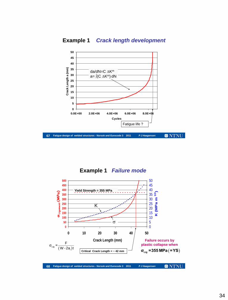
Example 1 Crack length development
0
5
10
15
20
25
30
35
40
45
50
0.0E+00 2.0E+06 4.0E+06 6.0E+06 8.0E+06
Cycles
Cra
ck
Le
ng
th a
(m
m)
da/dN=C Km
a= (C Km) dN
Fatigue life ?
Fatigue design of welded structures - Norsok and Eurocode 3 2011 P J Haagensen 68
0
50
100
150
200
250
300
350
400
450
500
0 10 20 30 40 50
Crack Length (mm)
Ligament(M
Pa)
05101520253035404550
K (
MP
a m
1/2
)
Example 1 Failure mode
Ligσ =355MPa =YS
Yield Strength = 355 MPa
Critical Crack Length = ~ 42 mm
K
Failure occurs by
plastic collapse when Lig
i
Fσ =
W - 2a t

35
Fatigue design of welded structures - Norsok and Eurocode 3 2011 P J Haagensen 69
Structural implications
Actions:
Establish failure criteria, apply safety factor (SF) to the critical crack length (ac) i.e. 42 mm / SF of 2.0; which gives allowable crack length = 21 mm
Establish inspection and maintenance schedules up to the allowable crack length.
When the crack length (a) reaches 21 mm: Remove component from service
Slow growth up to 10 mm, fast growth beyond 20 mm
Fatigue design of welded structures - Norsok and Eurocode 3 2011 P J Haagensen 70
Fracture mechanics - summary
Disadvantages:
Requires detailed information of structure geometry
Cycles to failure dependent on initial flaw geometry
Implementation at the design stage difficult
Determining SIFs can be involved and require special
numerical techniques
Advantages: Applicable to any type of structure with life dominated by crack growth
FEM, BEM or formulas can be used to determine SIF
Prediction of tolerable crack sizes in structure
Provide maintenance and inspection intervals

36
Fatigue design of welded structures - Norsok and Eurocode 3 2011 P J Haagensen 71
The BS 7910
standard
Fatigue design of welded structures - Norsok and Eurocode 3 2011 P J Haagensen 72
The critical value of the crack tip opening
displacement (CTOD = ) is C i.e. ductile
fracture occurs for when
The critical value of the stress intensity
factor for brittle materials is the fracture
toughness of the material, i.e. fracture
occurs when
K KIC
C

37
Fatigue design of welded structures - Norsok and Eurocode 3 2011 P J Haagensen 73
Guidance assessing the risk for unstable
fracture: • Methods for calculating stresses, external
and interior (or residual stresses)
• Calculation of SIFs for defect in question
• Materials data Use Level 1 or 2 fracture assessment
Fatigue design of welded structures - Norsok and Eurocode 3 2011 P J Haagensen 74
Guidance needed for fatigue crack
growth calculations:
Methods for calculating stresses, external
and interior (residual stresses)
Calculation of SIFs
Materials data (crack growth curves)
Acceptable flaw sizes
Remaining life
Inspection planning – length of inspection periods
Objectives
38
Fatigue design of welded structures - Norsok and Eurocode 3 2011 P J Haagensen 75
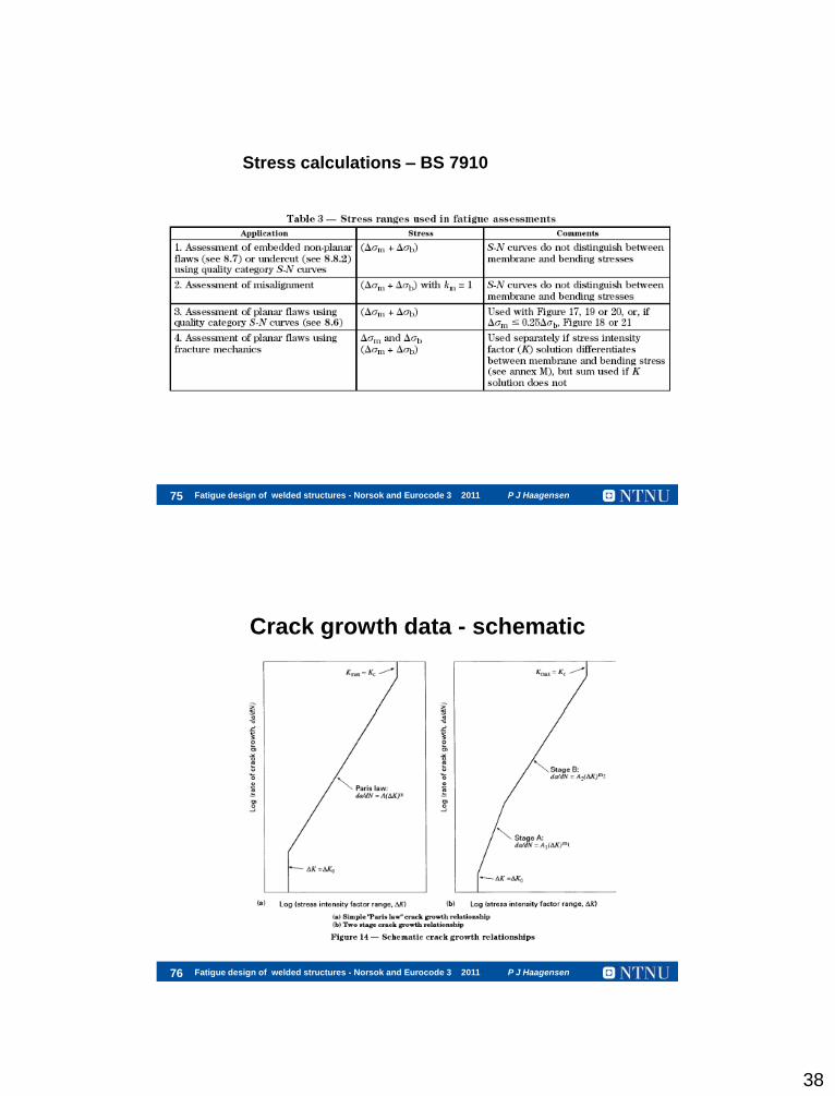
Stress calculations – BS 7910
Fatigue design of welded structures - Norsok and Eurocode 3 2011 P J Haagensen 76
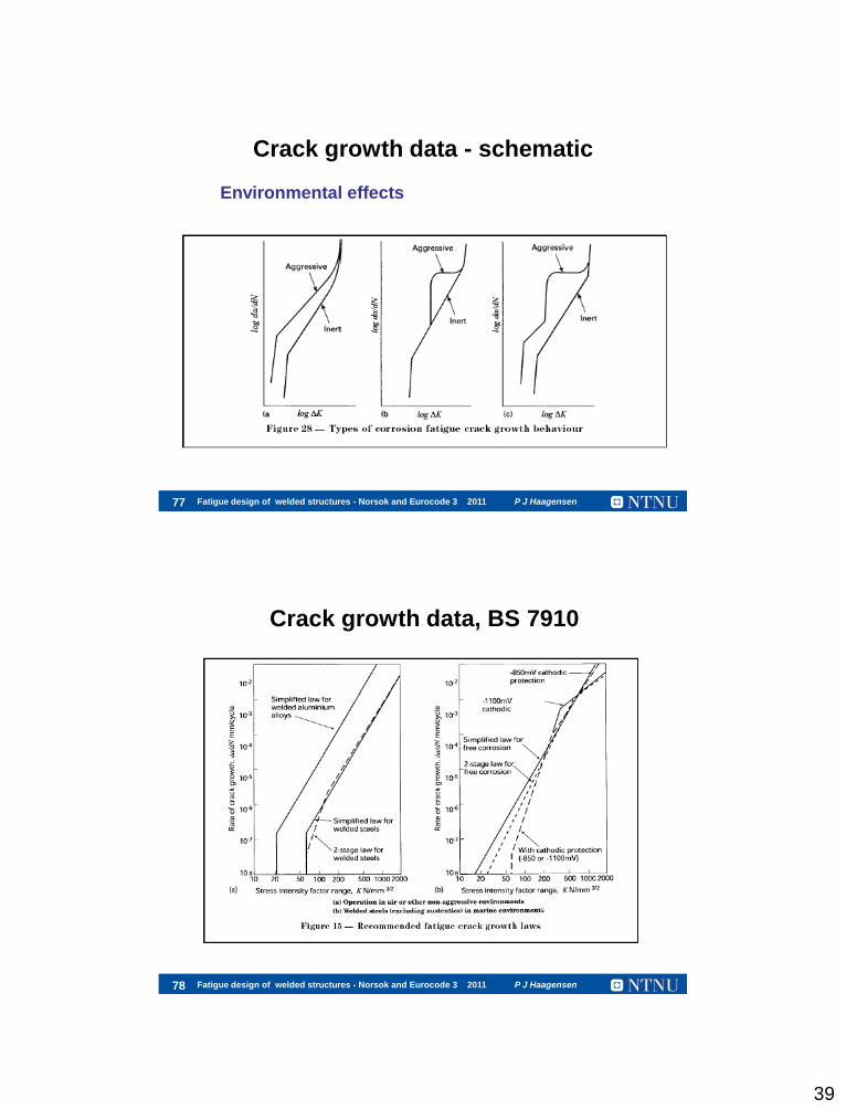
Crack growth data - schematic
39
Fatigue design of welded structures - Norsok and Eurocode 3 2011 P J Haagensen 77
Crack growth data - schematic
Environmental effects
Fatigue design of welded structures - Norsok and Eurocode 3 2011 P J Haagensen 78
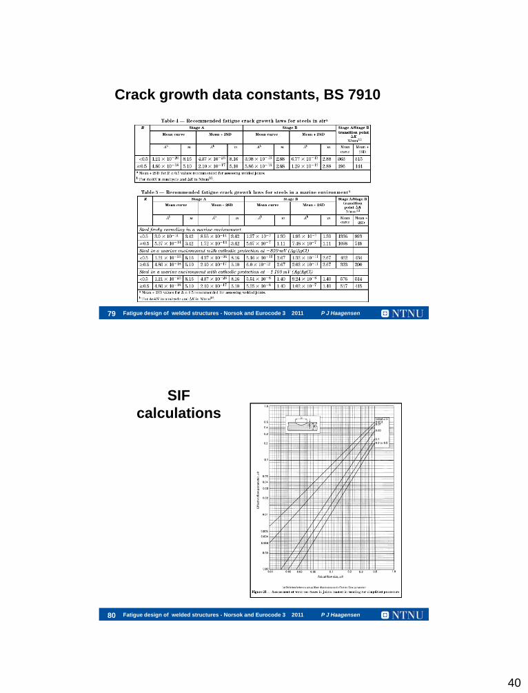
Crack growth data, BS 7910
40
Fatigue design of welded structures - Norsok and Eurocode 3 2011 P J Haagensen 79
Crack growth data constants, BS 7910
Fatigue design of welded structures - Norsok and Eurocode 3 2011 P J Haagensen 80
SIF
calculations

41
Fatigue design of welded structures - Norsok and Eurocode 3 2011 P J Haagensen 81
Quality category S-N curves
Fatigue design of welded structures - Norsok and Eurocode 3 2011 P J Haagensen 82
Symmary – Fracture mechanics
BS 7910 gives comprehensive guidance for assessing
the criticality of cracks or crack-like defects in welded
structures with respect to fracture and fatigue
The assessment can be made at different levels of
complexity
The effects of environment can be included in the
assessments