fast three-step phase-shifting algorithm
TRANSCRIPT
Fast three-step phase-shifting algorithm
Peisen S. Huang and Song Zhang
We propose a new three-step phase-shifting algorithm, which is much faster than the traditional three-step algorithm. We achieve the speed advantage by using a simple intensity ratio function to replace thearctangent function in the traditional algorithm. The phase error caused by this new algorithm iscompensated for by use of a lookup table. Our experimental results show that both the new algorithm andthe traditional algorithm generate similar results, but the new algorithm is 3.4 times faster. By imple-menting this new algorithm in a high-resolution, real-time three-dimensional shape measurement sys-tem, we were able to achieve a measurement speed of 40 frames per second at a resolution of 532 �
500 pixels, all with an ordinary personal computer. © 2006 Optical Society of AmericaOCIS codes: 120.0120, 120.2650, 100.5070.
1. Introduction
Phase wrapping in the phase-shifting method is theprocess of determining the phase values of the fringepatterns in the range of 0 to 2�.1 Phase unwrapping,on the other hand, is the process of removing the 2�discontinuity to generate a smooth phase map of theobject.2 Many algorithms have been developed to in-crease the processing speed of phase unwrapping.3–5
However, few discussions have been focused on in-creasing the speed of phase-wrapping algorithm.Traditional phase-wrapping algorithms involve thecalculation of an arctangent function, which is tooslow in the case when real-time processing is re-quired.6 Wan and Lin proposed a phase reductionalgorithm that uses the intensity of a fringe image toapproximate the phase.7 The resulting phase error iseliminated by averaging two reductions with ��2 dif-ference in phase. Even though its calculation of phasebased on intensity is fast, this algorithm requiresfinding the fringe centers and normalizing the fringepatterns before phase calculation, which slows downthe processing. The averaging method does eliminatemost part of the error, but not all. The residual errormay still be significant depending on applications.
Besides, when used for applications other than inter-ferometric testing of optics, the potential existence oftexture patterns on the object surface can cause er-rors in finding fringe centers, thus making the algo-rithm less reliable.
In recent years, we have been developing a high-resolution, real-time three-dimensional (3D) shapemeasurement system based on the phase-shiftingmethod.8,9 As the phase-shifting algorithm for thesystem, the three-step algorithm has been our choicebecause it requires the minimum number of fringeimages among all the existing algorithms. Less num-ber of images means faster image capture as well asprocessing, which translates into higher measure-ment speed. However, our experiments show thateven with the three-step algorithm, the image pro-cessing speed is still not fast enough for real-time 3Dshape reconstruction when an ordinary personalcomputer is used.6 The bottleneck lies in the calcula-tion of phase, which involves a computationally time-consuming arctangent function. To solve this problem,we propose a new three-step algorithm, which replacesthe calculation of the arctangent function with a sim-ple intensity ratio calculation and therefore is muchfaster than the traditional algorithm. The phase errorcaused by this replacement is compensated for by useof a lookup table (LUT). Our experimental resultsshow that both the new algorithm and the traditionalalgorithm generate similar results, but the new algo-rithm is 3.4 times faster. The adoption of this newalgorithm enabled us to successfully build a high-resolution, real-time 3D shape measurement systemthat captures, reconstructs, and displays the 3D shapeof the measured object at a speed of 40 frames per
P. S. Huang is with the Department of Mechanical Engineering,State University of New York (SUNY) at Stony Brook, Stony Brook,New York 11794-2300. S. Zhang ([email protected]) is withthe Department of Mathematics, Harvard University, Cambridge,Massachusetts 02138.
Received 1 November 2005; revised 6 March 2006; accepted 7March 2006; posted 13 March 2006 (Doc. ID 65703).
0003-6935/06/215086-06$15.00/0© 2006 Optical Society of America
5086 APPLIED OPTICS � Vol. 45, No. 21 � 20 July 2006
second �fps� and a resolution of 532 � 500 pixels, allwith an ordinary personal computer.10
Section 2 describes the principle of the proposedalgorithm. Section 3 discusses the error of the algo-rithm and proposes an error compensation method.Section 4 presents some experimental results. Fi-nally, Section 5 summarizes the work.
2. Principle
Among the various phase-shifting algorithms avail-able,1 the three-step algorithm requires the mini-mum number of frames and is the simplest to use.The following equations describe the intensity valuesof the three measured fringe patterns:
I1�x, y� � I��x, y� � I��x, y�cos���x, y� � ��, (1)
I2�x, y� � I��x, y� � I��x, y�cos���x, y��, (2)
I3�x, y� � I��x, y� � I��x, y�cos���x, y� � ��, (3)
where I��x, y� is the average intensity, I��x, y� is theintensity modulation, ��x, y� is the phase, and �is the phase step size. Even though � can be anyvalue, the two commonly used ones are � � 90° and� � 120°. The fast phase-shifting algorithm describedin this paper applies only to the case of � � 120°. For� � 120°, solving Eqs. (1) to (3) for the phase yields
��x, y� � arctan��3I1 � I3
2I2 � I1 � I3�. (4)
Since computers are not that good at computing thearctangent function, the traditional approach of cal-culating the phase using Eq. (4) directly is relativelyslow.
We encountered this problem in our effort todevelop a real-time 3D shape measurement systembased on fringe projection and phase shifting.8,11 As asolution, we proposed a novel phase-shifting method,namely, the trapezoidal phase-shifting method, thatused trapezoidal fringe patterns instead of the tradi-tional sinusoidal ones.6 By calculating an intensity ra-tio using a simple function, instead of phase using thearctangent function, we were able to increase the cal-culation speed by 4.6 times, which made the real-timereconstruction of 3D shapes possible. However, the useof trapezoidal fringe patterns brought some error dueto image defocus, even though the error is small, es-pecially when compared to the traditional intensity-ratio based methods.12–15 In the course of trying to dealwith this error, we discovered that if we apply thealgorithm developed for the trapezoidal method to si-nusoidal patterns, considering the sinusoidal patternsas the defocused trapezoidal patterns, and then com-
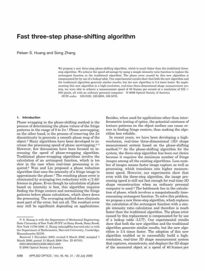
Fig. 1. Cross sections of the three phase-shifted sinusoidal fringepatterns. (a) I1(� � �120°). (b) I2(� � 0°). (c) I3(� � 120°).
Fig. 2. Cross sections of the intensity ratio image and the phaseimage. (a) Intensity ratio. (b) Phase.
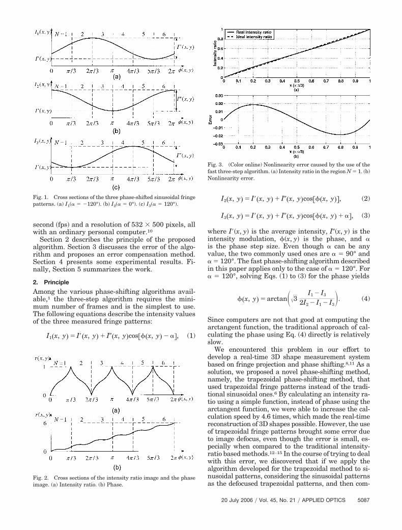
Fig. 3. (Color online) Nonlinearity error caused by the use of thefast three-step algorithm. (a) Intensity ratio in the region N � 1. (b)Nonlinearity error.
20 July 2006 � Vol. 45, No. 21 � APPLIED OPTICS 5087

pensate for the small error due to defocus, we couldpreserve the calculation speed of the trapezoidalmethod while achieving the same accuracy of the tra-ditional sinusoidal phase-shifting algorithm. The prin-ciple is described in the following paragraphs.
Figure 1 shows the cross sections of the threephase-shifted sinusoidal patterns with a phase stepsize of 120°. We divide the period evenly into sixregions �N � 1, 2, . . . , 6�, each covers an angularrange of 60°. In each region, the three curves do notcross. Therefore, we can denote the three intensityvalues to be Imin�x, y�, Imed�x, y�, and Imax�x, y�, whichare the minimum, median, and maximum intensityvalues, respectively. From these three intensity val-ues, we can calculate the so-called intensity ratior�x, y� as follows:
r�x, y� �Imed�x, y� � Imin�x, y�Imax�x, y� � Imin�x, y�
, (5)
which has a value between 0 and 1, as shown in Fig.2(a). The phase can then be calculated by the follow-ing equation:
���x, y� ��
32 � round�N � 12 �� ��1�N�1r�x, y�,
(6)
whose value ranges from 0 to 2�, as shown in Fig.2(b). As we can see from the figure, the phase calcu-lation is not accurate, but with a small error. In Sec-tion 3, we analyze this error and discuss how thiserror can be compensated for.
If multiple fringes are used, the phase calculatedby Eq. (6) will result in a sawtoothlike shape, just asin the traditional phase-shifting algorithm. In thiscase, the traditional phase-unwrapping algorithmhas to be used to obtain the continuous phase map.2
3. Error Analysis and Compensation
The fast three-step algorithm has the advantage offast processing speed over the traditional three-stepalgorithm. However, this method makes the linearphase value ��x, y� nonlinear, as shown in Fig. 2(b),which produces error. In this section, we discuss theerror caused by applying the fast three-step algo-rithm for sinusoidal patterns first and then proposean error compensation method.
From Fig. 2(b), we see that the error is periodicaland the pitch is ��3. Therefore, we only need to an-alyze the error in one period, say, ��x, y� � �0, ��3�.In this period, Imax�x, y� � I2�x, y�, Imed�x, y� �I1�x, y�, and Imin�x, y� � I3�x, y�. By substituting Eqs.(1) to (3) into Eq. (5), we obtain
r��� �I1 � I3
I2 � I3�
12 �
�32 tan�� �
�
6�. (7)
The right-hand side of this equation can be consid-ered as the sum of a linear and a nonlinear terms.
That is,
r��� ��
��3 � �r���, (8)
where the first term represents the linear relation-ship between r�x, y� and ��x, y� and the second term�r�x, y� is the nonlinearity error, which can be calcu-lated as follows:
�r��� � r��� ��
��3 �12 �
�32 tan�� �
�
6���
��3.
(9)
Figure 3(a) shows the plots of both the ideal linearratio and the real nonlinear ratio. Their difference,which is similar to a sine wave in shape, is shown inFig. 3(b). By taking the derivative of �r�x, y� withrespect to ��x, y� and setting it to zero, we can deter-mine that when
� ��
6 cos�1���3��6�, (10)
the ratio error reaches its maximum and minimumvalues, respectively, as
�r���max � �r������1� 0.0186, (11)
�r���min � �r������2� �0.0186. (12)
Therefore, the maximum ratio error is �r���max ��r���min � 0.037. Even though this error is relativelysmall, it needs to be compensated for when accuratemeasurement is required.
Since the ratio error is a systematic error, it can becompensated for by using an LUT method. In thisresearch, an 8-bit camera is used. Therefore the LUTis constructed with 256 elements, which representthe error values determined by �r���. If a higher-bit-depth camera is used, the size of the LUT should beincreased accordingly. Because of the periodical na-ture of the error, this same LUT can be applied to allsix regions. Finally, it should be noted that the phaseerror can be found by simply multiplying the inten-sity ratio error by ��3.
4. Experiments
To verify the effectiveness of the proposed algorithmexperimentally, we used a projector to project sinusoi-dal fringe patterns onto the object and an 8-bit black-and-white (B�W) CCD camera with 532 � 500 pixelsto capture the three phase-shifted fringe images.9First, we used a flat board as the target object. Thecaptured three fringe images are shown in Fig. 4(a)–4(c). For comparison, we applied both the traditionalalgorithm and the newly proposed algorithm to thesame fringe images. Figures 5(a), 5(b), and 5(c) showthe intensity ratio errors of the traditional three-step
5088 APPLIED OPTICS � Vol. 45, No. 21 � 20 July 2006
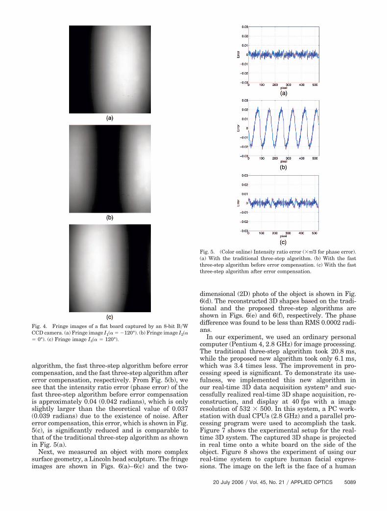
algorithm, the fast three-step algorithm before errorcompensation, and the fast three-step algorithm aftererror compensation, respectively. From Fig. 5(b), wesee that the intensity ratio error (phase error) of thefast three-step algorithm before error compensationis approximately 0.04 (0.042 radians), which is onlyslightly larger than the theoretical value of 0.037(0.039 radians) due to the existence of noise. Aftererror compensation, this error, which is shown in Fig.5(c), is significantly reduced and is comparable tothat of the traditional three-step algorithm as shownin Fig. 5(a).
Next, we measured an object with more complexsurface geometry, a Lincoln head sculpture. The fringeimages are shown in Figs. 6(a)–6(c) and the two-
dimensional (2D) photo of the object is shown in Fig.6(d). The reconstructed 3D shapes based on the tradi-tional and the proposed three-step algorithms areshown in Figs. 6(e) and 6(f), respectively. The phasedifference was found to be less than RMS 0.0002 radi-ans.
In our experiment, we used an ordinary personalcomputer (Pentium 4, 2.8 GHz) for image processing.The traditional three-step algorithm took 20.8 ms,while the proposed new algorithm took only 6.1 ms,which was 3.4 times less. The improvement in pro-cessing speed is significant. To demonstrate its use-fulness, we implemented this new algorithm inour real-time 3D data acquisition system9 and suc-cessfully realized real-time 3D shape acquisition, re-construction, and display at 40 fps with a imageresolution of 532 � 500. In this system, a PC work-station with dual CPUs �2.8 GHz� and a parallel pro-cessing program were used to accomplish the task.Figure 7 shows the experimental setup for the real-time 3D system. The captured 3D shape is projectedin real time onto a white board on the side of theobject. Figure 8 shows the experiment of using ourreal-time system to capture human facial expres-sions. The image on the left is the face of a human
Fig. 4. Fringe images of a flat board captured by an 8-bit B�WCCD camera. (a) Fringe image I1(� � �120°). (b) Fringe image I2(�� 0°). (c) Fringe image I3(� � 120°).
Fig. 5. (Color online) Intensity ratio error (��/3 for phase error).(a) With the traditional three-step algorithm. (b) With the fastthree-step algorithm before error compensation. (c) With the fastthree-step algorithm after error compensation.
20 July 2006 � Vol. 45, No. 21 � APPLIED OPTICS 5089
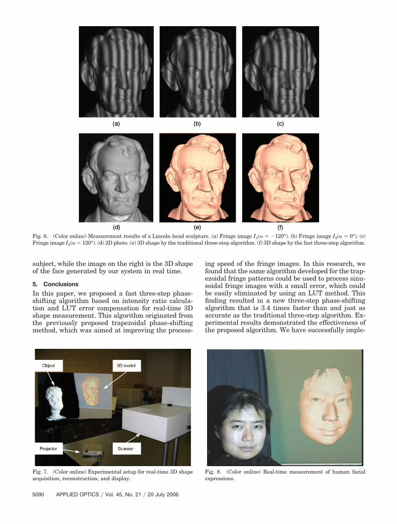
subject, while the image on the right is the 3D shapeof the face generated by our system in real time.
5. Conclusions
In this paper, we proposed a fast three-step phase-shifting algorithm based on intensity ratio calcula-tion and LUT error compensation for real-time 3Dshape measurement. This algorithm originated fromthe previously proposed trapezoidal phase-shiftingmethod, which was aimed at improving the process-
ing speed of the fringe images. In this research, wefound that the same algorithm developed for the trap-ezoidal fringe patterns could be used to process sinu-soidal fringe images with a small error, which couldbe easily eliminated by using an LUT method. Thisfinding resulted in a new three-step phase-shiftingalgorithm that is 3.4 times faster than and just asaccurate as the traditional three-step algorithm. Ex-perimental results demonstrated the effectiveness ofthe proposed algorithm. We have successfully imple-
Fig. 6. (Color online) Measurement results of a Lincoln head sculpture. (a) Fringe image I1(� � �120°). (b) Fringe image I2(� � 0°). (c)Fringe image I3(� � 120°). (d) 2D photo. (e) 3D shape by the traditional three-step algorithm. (f) 3D shape by the fast three-step algorithm.
Fig. 7. (Color online) Experimental setup for real-time 3D shapeacquisition, reconstruction, and display.
Fig. 8. (Color online) Real-time measurement of human facialexpressions.
5090 APPLIED OPTICS � Vol. 45, No. 21 � 20 July 2006

mented this algorithm in our real-time 3D shapemeasurement system, which resulted in a frame rateof 40 fps and a resolution of 532 � 500 points.
This work was supported by the National ScienceFoundation under grant CMS-9900337 and the Na-tional Institute of Health under grant RR13995.
References1. D. Malacara, ed., Optical Shop Testing (Wiley, 1992).2. D. C. Ghiglia and M. D. Pritt, Two-Dimensional Phase Un-
wrapping: Theory, Algorithms, and Software (Wiley, 1998).3. M. A. Herráez, D. R. Burton, M. J. Lalor, and M. A. Gdeisat,
“Fast two-dimensional phase-unwrapping algorithm based onsorting by reliability following a noncontinuous path,” Appl.Opt. 41, 7437–7444 (2002).
4. M. A. Herráez, M. A. Gdeisat, D. R. Burton, and M. J. Lalor,“Robust, fast, and effective two-dimensional automatic phaseunwrapping algorithm based on image decomposition,” Appl.Opt. 41, 7445–7455 (2002).
5. A. Asundi and W. Zhou, “Fast phase-unwrapping algorithmbased on a gray-scale mask and flood fill,” Appl. Opt. 37, 5416–5420 (1998).
6. P. Huang, S. Zhang, and F.-P. Chiang, “Trapezoidal phase-shifting method for 3-D shape Measurement,” in Two- andThree-Dimensional Vision Systems for Inspection, Control, andMetrology II, K. G. Harding, ed., Proc. SPIE 5606, 142–152(2004).
7. D.-S. Wan and D.-T. Lin, “Ronchi test and a new phase reduc-tion algorithm,” Appl. Opt. 29, 3255–3265 (1990).
8. P. S. Huang, C. Zhang, and F. P. Chiang, “High-speed 3-Dshape measurement based on digital fringe projection,” Opt.Eng. 42, 163–168 (2003).
9. S. Zhang and P. Huang, “High-resolution, real-time 3-D shapeacquisition,” presented at the IEEE Computer Vision and Pat-tern Recognition Workshop (CVPRW’04), Washington, D.C.,27 June–2 July 2004.
10. S. Zhang, “High-resolution, real-time 3D shape measurement,”Ph.D. thesis (State University of New York at Stony Brook,2005).
11. C. Zhang, P. S. Huang, and F.-P. Chiang, “Microscopic phase-shifting profilometry based on digital micromirror device tech-nology,” Appl. Opt. 41, 5896–5904 (2002).
12. B. Carrihill and R. Hummel, “Experiments with the intensityratio depth sensor,” Comput. Vis. Graph. Image Process. 32,337–358 (1985).
13. T. Miyasaka, K. Kuroda, M. Hirose, and K. Araki, “Reconstruc-tion of realistic 3D surface model and 3D animation from rangeimages obtained by real time 3D measurement system,” inProceedings of the International Conference on Pattern Recog-nition 2000 (IEEE, 2000), pp. 594–598.
14. T. Miyasaka, K. Kuroda, M. Hirose, and K. Araki, “High speed3-D measurement system using incoherent light source forhuman performance analysis,” in XIXth Congress of the Inter-national Society for Photogrammetry and Remote Sensing,K. J. B. M. Molenaar, ed. (ISPRS, 2000), pp. 16–23.
15. G. Chazan and N. Kiryati, “Pyramidal intensity-ratio depthsensor,” Tech. Rep. 121 (Israel Institute of Technology,1995).
20 July 2006 � Vol. 45, No. 21 � APPLIED OPTICS 5091