fast reroute with segment routing - extending fast reroute
TRANSCRIPT
T E C H N O L O G Y W H I T E P A P E R
Fast Reroute with Segment Routing Extending Fast Reroute coverage in LDP-based MPLS networks
Segment Routing (SR) is an emerging technology for IP/Multiprotocol Label Switching
(MPLS) networks that enables source routing. Before SR was introduced, IP Fast Reroute
and Loop-Free Alternates (LFAs) were not widely deployed. The level of coverage depended
on the network topology, and LFA imposed requirements such as the dynamic setup and
teardown of targeted Label Distribution Protocol (LDP) sessions. When SR and source
routing are combined with Fast Reroute techniques such as LFA variants, Fast Reroute
can deliver 100-percent network coverage regardless of the topology. In addition, traffic-
engineering capabilities that were previously only possible with Resource Reservation
Protocol - Traffic Engineering (RSVP-TE) can be offered without the associated scaling
constraints. Delivering Fast Reroute without the complexity and constraints of RSVP-TE
is appealing to service providers, particularly those that deliver services with stringent
Service Level Agreements. This paper describes the delivery of Fast Reroute using SR
and the enhancement of Fast Reroute coverage in LDP-based MPLS networks.

Table of contents
Segment Routing technology overview / 1
Segment identifiers / 2
Node-SID and Prefix-SID / 2
Adj-SID / 3
IP Fast Reroute / 4
Loop-Free Alternate / 5
Remote LFA / 6
Directed LFA / 8
Topology Independent LFA / 9
Extending Fast Reroute coverage with SR / 11
SR-to-LDP interworking / 11
Fast Reroute for LDP using SR / 12
Conclusion / 14
Acronyms / 15
References / 15

1
Fast Reroute with Segment Routing
Alcatel-Lucent Strategic White Paper
Segment Routing technology overviewSegment Routing (SR) is an emerging technology for IP/Multiprotocol Label Switching (MPLS) networks that provides the ability to source-route. With source routing, operators can specify a path from ingress to egress using a forwarding path that is independent of the shortest path determined by the Interior Gateway Protocol (IGP). Before SR was introduced, IP Fast Reroute and Loop-Free Alternates (LFAs) were not widely deployed. The level of coverage depended on the network topology, and LFA imposed requirements such as the dynamic setup and teardown of targeted Label Distribution Protocol (LDP) sessions, which many operators do not favor.
When SR and source routing are combined with Fast Reroute techniques such as LFA variants, Fast Reroute can deliver 100-percent network coverage regardless of the network topology. In addition, operators gain traffic-engineering capabilities — previously only possible with Resource Reservation Protocol - Traffic Engineering (RSVP-TE) — without the associated scaling constraints.
To enable source routing, SR provides a tunneling mechanism. An SR path (SR tunnel) is encoded as a sequential list of sub-paths or segments that are advertised to the SR domain using extensions to link-state routing protocols such as Intermediate System to Intermediate System (IS-IS) or Open Shortest Path First (OSPF). An SR tunnel can contain a single segment that represents the destination node, or it can contain a segment list that represents the set of segments that a given tunnel must traverse.
The SR tunnel can be established over an IPv4/IPv6 MPLS infrastructure or an IPv6 infrastructure and is encoded as a:
• Single MPLS label or an ordered list of hops represented as a stack of labels (with no change to the MPLS data plane)
• Single IPv6 address or an ordered list of hops represented by a number of IPv6 addresses contained in an IPv6 extension header
The segments that an ingress router imposes for a particular tunnel act as a set of instructions, such as “go to node M using the shortest path” or “go to node N using link/node/explicit-route L”. Figure 1 shows an SR domain represented as segments.
Figure 1. SR domain represented as segments
Segment
R4R1 R3R2
R5 R6

2
Fast Reroute with Segment Routing
Alcatel-Lucent Strategic White Paper
When MPLS is used to instantiate SR tunnels, the MPLS forwarding plane does not change. SR uses extensions to the link-state IGP to flood Segment Identifiers (SIDs) in the form of MPLS labels. No LDP and/or RSVP control plane is required although it is acceptable to run these in conjunction with SR: because the LDP and RSVP label spaces do not overlap, they do not affect each other. Each SID is a 32-bit entity, with the MPLS label encoded as the 20 right-most bits of the segment.
When SR is instantiated over the MPLS data plane, the following actions apply:
• A list of segments is represented as a stack of labels.
• The active segment is the top label.
• The CONTINUE operation is implemented as an MPLS swap operation.
• The NEXT operation is implemented as an MPLS pop operation.
• The PUSH operation is implemented as an MPLS push operation.
Unlike RSVP-TE based Label Switched Paths (LSPs), in which the mid-points hold state, SR requires that only the ingress provider-edge (PE) router holds state. For transit or egress SR routers, the required state information is contained in the segment list.
The remainder of this paper focuses on the instantiation of SR using MPLS, the likely choice for most early adopters. The term LSP is used interchangeably between RSVP-TE and SR.
Segment identifiersIn an SR domain, each segment is assigned a Prefix-SID or an Adjacency-SID (Adj-SID). A Prefix-SID is globally unique within the IGP/SR domain. The SID value is allocated from a unique pool called the SR Global Block (SRGB).
In an MPLS network, the SRGB is a set of labels reserved specifically for SR use. A Prefix-SID represents the ECMP-aware shortest-path route to the related prefix and is typically a multi-hop path.
Node-SID and Prefix-SIDA Node-SID is a special type of Prefix-SID that is used to identify a particular router (loopback/system address) in the domain. The Node-SID is identified by an N flag set to 1 in the Prefix-SID sub - Type Length Value (TLV) that IS-IS or OSPF uses to advertise the SID. Because the Node-SID is a Prefix-SID, it also represents the Equal Cost Multi-Path (ECMP)-aware shortest-path route to the related prefix, typically a multi-hop path.
When an SR router advertises its Node-SID to the SR domain, all routers in the domain install the node segment in the data plane.1 In the example shown in Figure 2, PE2 advertises a Node-SID of 800 to the SR domain. When PE1 wants to forward SR tunnel-encapsulated traffic toward PE2, it pushes on the node segment {800} and forwards the packet using its shortest path toward PE2. Routers P1 and P2 each implement a CONTINUE (swap) action in the data plane.
1 This paper assumes the use of absolute SID values, in which all SR routers in the domain use a single consistent SRGB. Indexing, an alternative option, is possible: SR routers have a different start point (start label) in the SRGB and advertise an offset label called an SID index. The advertised index is summed with the start point to create behavior analogous to LDP in independent label-distribution mode.
3
Fast Reroute with Segment Routing
Alcatel-Lucent Strategic White Paper
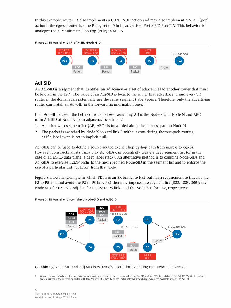
In this example, router P3 also implements a CONTINUE action and may also implement a NEXT (pop) action if the egress router has the P flag set to 0 in its advertised Prefix-SID Sub-TLV. This behavior is analogous to a Penultimate Hop Pop (PHP) in MPLS.
Figure 2. SR tunnel with Prefix-SID (Node-SID)
P3PE1 P2 PE2P1
800
Packet
800
Packet
800
Packet
Packet
Node-SID 800
FEC PE2PUSH 800
CONTINUE800 –> 800
CONTINUE800 –> 800
NEXT800
Adj-SIDAn Adj-SID is a segment that identifies an adjacency or a set of adjacencies to another router that must be known in the IGP.2 The value of an Adj-SID is local to the router that advertises it, and every SR router in the domain can potentially use the same segment (label) space. Therefore, only the advertising router can install an Adj-SID in the forwarding information base.
If an Adj-SID is used, the behavior is as follows (assuming AB is the Node-SID of Node N and ABC is an Adj-SID at Node N to an adjacency over link L):
1. A packet with segment list {AB, ABC} is forwarded along the shortest path to Node N.
2. The packet is switched by Node N toward link L without considering shortest-path routing, as if a label-swap is set to implicit null.
Adj-SIDs can be used to define a source-routed explicit hop-by-hop path from ingress to egress. However, constructing lists using only Adj-SIDs can potentially create a deep segment list (or in the case of an MPLS data plane, a deep label stack). An alternative method is to combine Node-SIDs and Adj-SIDs to exercise ECMP paths to the next specified Node-SID in the segment list and to enforce the use of a particular link (or links) from that node.
Figure 3 shows an example in which PE1 has an SR tunnel to PE2 but has a requirement to traverse the P2-to-P5 link and avoid the P2-to-P3 link. PE1 therefore imposes the segment list {300, 1003, 800}: the Node-SID for P2, P2’s Adj-SID for the P2-to-P5 link, and the Node-SID for PE2, respectively.
Figure 3. SR tunnel with combined Node-SID and Adj-SID
P3
PE1
P2
PE2
P1
P6P5P4
800
Packet
800
Packet
800
1003
300
Packet
Packet
Node-SID 800
Node-SID 300
Adj-SID 1003
CONTINUE800 –> 800
CONTINUE300 –> 300
NEXT(300, 1003)
NEXT800
800
1003
300
Packet
Combining Node-SID and Adj-SID is extremely useful for extending Fast Reroute coverage.
2 Where a number of adjacencies exist between two routers, a router can advertise an Adjacency-Set SID (Adj-Set SID) in addition to the Adj-SID. Traffic that subse-quently arrives at the advertising router with this Adj-Set SID is load-balanced (potentially with weighting) across the available links of the Adj-Set.
4
Fast Reroute with Segment Routing
Alcatel-Lucent Strategic White Paper
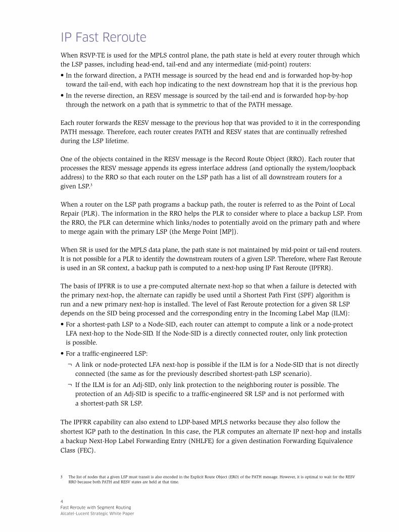
IP Fast RerouteWhen RSVP-TE is used for the MPLS control plane, the path state is held at every router through which the LSP passes, including head-end, tail-end and any intermediate (mid-point) routers:
• In the forward direction, a PATH message is sourced by the head end and is forwarded hop-by-hop toward the tail-end, with each hop indicating to the next downstream hop that it is the previous hop.
• In the reverse direction, an RESV message is sourced by the tail-end and is forwarded hop-by-hop through the network on a path that is symmetric to that of the PATH message.
Each router forwards the RESV message to the previous hop that was provided to it in the corresponding PATH message. Therefore, each router creates PATH and RESV states that are continually refreshed during the LSP lifetime.
One of the objects contained in the RESV message is the Record Route Object (RRO). Each router that processes the RESV message appends its egress interface address (and optionally the system/loopback address) to the RRO so that each router on the LSP path has a list of all downstream routers for a given LSP.3
When a router on the LSP path programs a backup path, the router is referred to as the Point of Local Repair (PLR). The information in the RRO helps the PLR to consider where to place a backup LSP. From the RRO, the PLR can determine which links/nodes to potentially avoid on the primary path and where to merge again with the primary LSP (the Merge Point [MP]).
When SR is used for the MPLS data plane, the path state is not maintained by mid-point or tail-end routers. It is not possible for a PLR to identify the downstream routers of a given LSP. Therefore, where Fast Reroute is used in an SR context, a backup path is computed to a next-hop using IP Fast Reroute (IPFRR).
The basis of IPFRR is to use a pre-computed alternate next-hop so that when a failure is detected with the primary next-hop, the alternate can rapidly be used until a Shortest Path First (SPF) algorithm is run and a new primary next-hop is installed. The level of Fast Reroute protection for a given SR LSP depends on the SID being processed and the corresponding entry in the Incoming Label Map (ILM):
• For a shortest-path LSP to a Node-SID, each router can attempt to compute a link or a node-protect LFA next-hop to the Node-SID. If the Node-SID is a directly connected router, only link protection is possible.
• For a traffic-engineered LSP:
¬ A link or node-protected LFA next-hop is possible if the ILM is for a Node-SID that is not directly connected (the same as for the previously described shortest-path LSP scenario).
¬ If the ILM is for an Adj-SID, only link protection to the neighboring router is possible. The protection of an Adj-SID is specific to a traffic-engineered SR LSP and is not performed with a shortest-path SR LSP.
The IPFRR capability can also extend to LDP-based MPLS networks because they also follow the shortest IGP path to the destination. In this case, the PLR computes an alternate IP next-hop and installs a backup Next-Hop Label Forwarding Entry (NHLFE) for a given destination Forwarding Equivalence Class (FEC).
3 The list of nodes that a given LSP must transit is also encoded in the Explicit Route Object (ERO) of the PATH message. However, it is optimal to wait for the RESV RRO because both PATH and RESV states are held at that time.

5
Fast Reroute with Segment Routing
Alcatel-Lucent Strategic White Paper
Loop-Free AlternateWhen a PLR attempts to pre-compute an alternate backup next-hop, the backup next-hop is generically called an LFA. The existence of a suitable LFA — and therefore the percentage of Fast Reroute coverage that a given network can obtain depends on the topology.
Figure 4 shows a simple topology in which the numbers beside each link represent the IGP metric. Router S, the source or calculating router, computes a shortest path to D (destination) and uses router E as its primary next-hop. Router S also computes that router N (neighbor of S) is a feasible alternate next-hop for destination D and installs it as a backup. If the S-to-E link fails, router S forwards traffic to the pre-computed backup router N, which then forwards the traffic to D as a suitable LFA.
Figure 4. Topology with suitable LFA
5 8
4 3
NE
S
D
Figure 5 shows the same topology, but the metric for the N-to-D link has changed from the value in Figure 4. Router S computes the shortest path to D and uses E as its primary next-hop. Router N is not a suitable LFA because the cost of the path from N to D is 30 whereas the cost to D by way of S would be 17. If the S-to-E link fails and router S forwards traffic for D to N, N forwards it back toward S, and a transient loop (also called a micro-loop) exists until the next SPF is executed. Therefore, no suitable LFA exists in this simple topology.
Figure 5. Topology with no suitable LFA
5 8
4
NE
S
D30
For a basic local LFA calculation, a neighbor N can provide an LFA only if it meets the inequality criteria defined in RFC 5286: Basic Specification for IP Fast Reroute: Loop-Free Alternates:4
Link Protect (Inequality 1): Shortest_Distance (N, D) < Shortest_Distance (N, S) + Shortest_Distance (S, D)
Node Protect (Node E) (Inequality 3):Shortest_Distance (N, D) < Shortest_Distance (N, E) + Shortest_Distance (E, D)
Basic LFA is simple but it depends on the topology, so Fast Reroute coverage varies among networks. Fast Reroute has poor coverage in ring and square topologies. However, Fast Reroute can achieve as high as 85- to 90-percent coverage in partially meshed topologies.
4 IETF, RFC 5286: Basic Specification for IP Fast Reroute: Loop-Free Alternates, September 2008. tools.ietf.org/html/rfc5286

6
Fast Reroute with Segment Routing
Alcatel-Lucent Strategic White Paper
Remote LFARemote LFA (RLFA) is defined in the IETF Internet Draft Remote Loop-Free Alternate (LFA) Fast Re-Route (FRR).5 RLFA attempts to extend the basic next-hop LFA repair mechanism to increase Fast Reroute coverage. If a link cannot be protected for a given destination with local, adjacent LFA neighbors, RLFA attempts to create a virtual LFA by using a tunnel to carry packets to a point in the network where they will not be looped back.
Figure 6 shows a simple topology in which router S cannot fully protect the S-to-E link. Router C is ECMP from Router S, so some flows are affected if the S-to-E link fails, but routers D and E cannot be protected by LFAs. If the S-to-E link fails and router S forwards traffic destined for D or E toward router A, router A forwards the packets back to router S and a micro-loop exists until the next SPF is executed.
Figure 6. Topology with no suitable LFA
100
100
100
100
100
100
A D
ES
CB
To compute an RLFA repair path for the S-to-E link that protects D and E, router S must determine the point in the network to which packets can be tunneled, such that when they emerge from the tunnel they are forwarded toward the destination instead of being looped back toward S. (This is a per-link LFA calculation, not a per-prefix LFA calculation used with regular LFA. This approach provides protection for all destinations that share the protected link.)
Router S determines the set of routers that can be reached from S without traversing the S-to-E link (S’s extended P-space) and matches this with the set of routers that can reach E without traversing the S-to-E link (E’s Q-space).
S’s P-space, which covers routers A and B, is derived by calculating a Shortest Path Tree (SPT) rooted at S. However, on the premise that, should S force a packet toward its neighbor, the cost would be lower for that neighbor to forward the packet toward the destination using any other path than the link back toward S (and then across the S-to-E link), it is possible to root the P-space SPT at S’s neighbors. This is S’s extended P-space and covers routers A, B and C (highlighted in green in Figure 7). The use of extended P-space enables router S to reach potential tunnel repair points that otherwise would not be possible using the P-space alone.
E’s Q-space is calculated using a reverse SPT rooted at E to calculate the routers that can reach E without going through the S-to-E link. A reverse SPT calculates the cost toward the root rather than from it, yielding the best paths toward the root from other nodes in the network. In Figure 7, E’s Q-space equates to routers D and C (highlighted in red).
5 IETF, Internet Draft: Remote Loop-Free Alternate (LFA) Fast Re-Route (FRR), January 30, 2015. draft-ietf-rtgwg-remote-lfa

7
Fast Reroute with Segment Routing
Alcatel-Lucent Strategic White Paper
Figure 7. S’s extended P-space and E’s Q-space
100
100
100100
100100
A D
ES
CB
The point at which the extended P-space and Q-space intersect is called the PQ node, to which a repair tunnel can be built. In the example in Figure 7, the PQ node is router C. If a repair tunnel is built from S to C and C becomes S’s neighbor through this tunnel, C can become an RLFA for routers D and E. However, the tunnel can only be used for repair traffic and not as a cut-through link for non-repair traffic.
The IETF Remote LFA FRR Internet Draft does not specify which tunneling mechanism is used to create the repair tunnel. However, the draft states that if the network runs MPLS, a simple label stack could be used to provide the tunnel. Prior to the introduction of SR, the repair tunnel could therefore be LDP-over-RSVP or LDP-over-LDP.
Link-layer LDP or RSVP is used to exchange outer labels between directly adjacent neighbors (C to B, B to A, A to S). Targeted LDP is used to exchange inner labels between the non-adjacent routers S and C that form the repair tunnel.
Both LDP-over-RSVP and LDP-over-LDP approaches have disadvantages:
• LDP-over-RSVP: RSVP LSPs must be provisioned to potential repair-tunnel endpoints. These LSPs must only be included in LFA SPFs to ensure that only repair traffic is forwarded through the tunnels. Operators must carefully plan this typically manual provisioning process.
• LDP-over-LDP: Targeted LDP sessions must be dynamically created for potential repair points to signal inner labels. After a topology change, these sessions must be dynamically torn down, cleaned up and reestablished to new post-reconvergence repair points. Many operators do not favor this dynamic behavior.
The introduction of SR removes the requirement for a targeted LDP session over the repair tunnel to the PQ node. The repair node can swap or push all the necessary labels to ensure that:
• Packets are forwarded correctly to the PQ node through the repair tunnel.
• The PQ node can correctly forward packets correctly toward the destination as they exit the repair tunnel.
The labels do not need to be advertised or negotiated between the repair tunnel source and endpoint.

8
Fast Reroute with Segment Routing
Alcatel-Lucent Strategic White Paper
For example, if a shortest-path SR LSP to a remote Node-SID N is being repaired, the repair node implements the following actions:
• CONTINUE (swap) action of the top label N (in the case of absolute SIDs, CONTINUE N for N): This label represents the ECMP-aware shortest path to the destination node and ensures that the PQ node can correctly forward the packet when it leaves the repair tunnel.
• PUSH action of the label representing the Node-SID of the PQ node on top of the label stack, to ensure that traffic is directed to the PQ node.
In addition to removing the requirement for targeted LDP sessions over repair tunnels when SR is used, RLFA has better coverage properties than basic LFA when the remote PQ node is reachable using a shortest-path tunnel. RLFA can reach coverage as high as 98 percent.
Directed LFAThe IETF Internet Draft IP Fast Reroute using tunnels provided much of the groundwork for IPFRR and introduced the concept of Directed LFA (DLFA).6 With DLFA, the originator of a repair tunnel can instruct that, when a packet is decapsulated from the repair tunnel, it is forwarded over a particular adjacency by the tunnel release point. This action effectively extends the tunnel by at least one hop.
For example, if the metric of the B-to-C link in the previous topology is increased to 400, no PQ-intersect node exists. Therefore router S cannot protect the S-to-E link for routers C, D or E, as shown in Figure 8.
Figure 8. S’s extended P-space and E’s Q-space with modified metric for the B-to-C link
100
400
100100
100100
A D
ES
CB
However, if router S could forward the repair traffic to router B with an instruction to send it over the adjacency to C, full coverage would be restored. This is the concept of a DLFA — with SR, a simple combination of a Node-SID and an Adj-SID. As shown in Figure 9, the outer label (Node-SID) represents the tunnel release point (router B), and the inner label (Adj-SID) represents the relevant adjacency (B-to-C link).
Figure 9. DLFA
Packet
100
100
100Adj-SID 1003
Node-SID 300
NEXT(300, 1003)
1003
300
Packet
1003
300
Packet
A D
ES
CB
6 IETF, Internet Draft: IP Fast Reroute using tunnels, April 2005. draft-bryant-ipfrr-tunnels

9
Fast Reroute with Segment Routing
Alcatel-Lucent Strategic White Paper
DLFA resolves the coverage issues of RLFA and, like RLFA, does not require targeted LDP sessions (dynamic or otherwise) to signal inner labels. DLFA is intended to cover cases in which the repair tunnel endpoint is not reachable using a shortest-path calculation. DLFA can increase coverage as follows:
• One-hundred-percent coverage for link protection with a maximum of two labels (assuming links have symmetric metrics)
• Almost 100-percent coverage for node protection with a maximum of four labels imposed at the PLR (coverage of 99.92 percent with two labels and 99.96 percent with three labels)
Topology Independent LFAA PLR that has a pre-computed alternate backup next-hop can switch from primary next-hop to backup next-hop in the order of milliseconds (not including the time taken to detect the failure). However, during a failure there are often two transitions:
• From the primary steady-state path (the pre-convergence path) to the Fast Reroute path
• From the Fast Reroute path to the post-convergence path
Figure 10 shows an example in which router R3 attempts to find an LFA for destination D to protect the R3-to-R4 link on which the primary (pre-convergence) path is routed. The shortest path is R1-R2-R4, but router R1 is not a feasible LFA backup next-hop.7 Router R3 therefore programs an LFA backup of R5 using the path R5-R6-R7-R4, resulting in the following:
• The pre-convergence path is the R3-to-R4 link (illustrated as a green line).
• When the R3-to-R4 link fails, the first transition moves traffic to the Fast Reroute backup path R3-R5-R6-R7-R4 (illustrated as a yellow line).
• When the IGP has re-converged, the second transition moves traffic to the post-convergence path R3-R1-R2-R4 (illustrated as a red line).
Figure 10. Two convergence transitions with LFA
R2
S D
R1
R4
R7R6R5
Pre-convergence Post-convergencePost-FRR
25
10
10 10
30 10
10 15
R3
7 No PQ-intersect node exists on the R1-R2-R4 path, so there is no suitable RLFA repair tunnel endpoint. DLFA could be used as a tunnel repair mechanism, but as will be discussed, TI-LFA makes use of that.
10
Fast Reroute with Segment Routing
Alcatel-Lucent Strategic White Paper
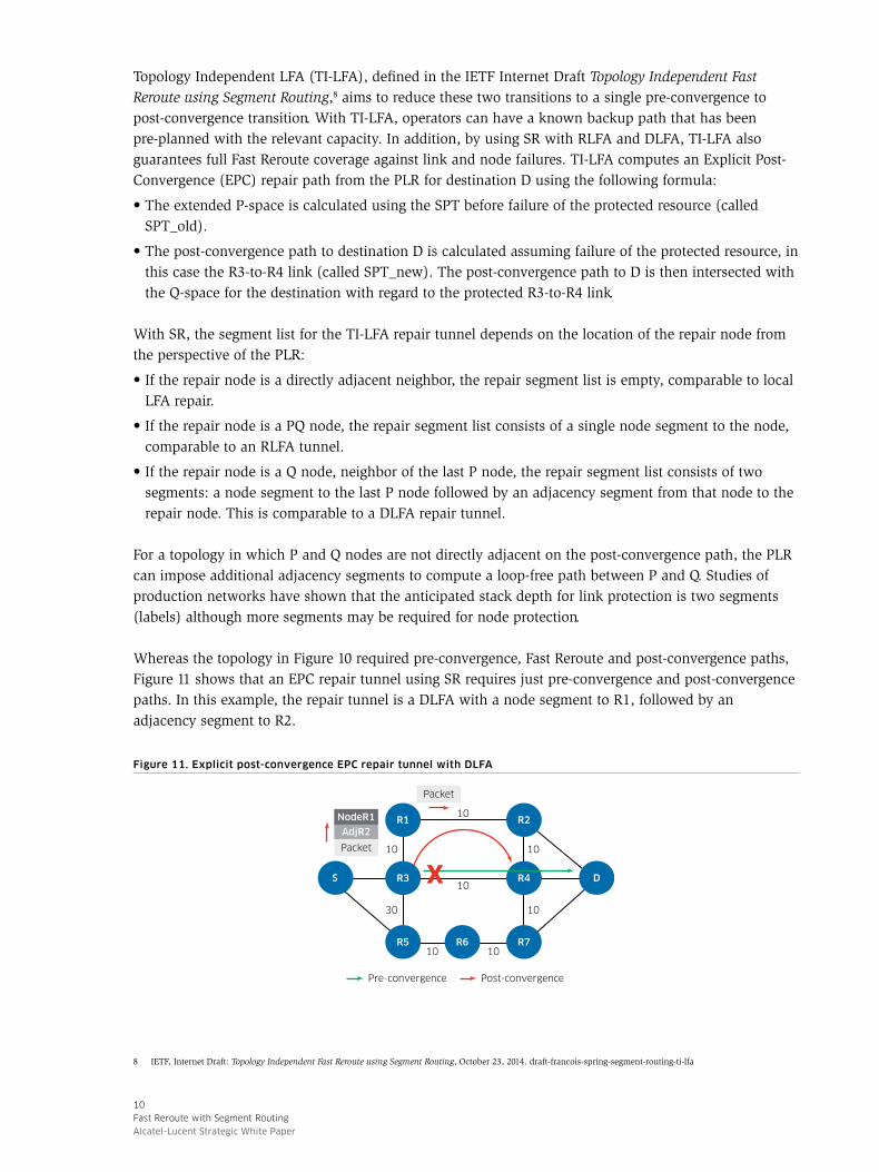
Topology Independent LFA (TI-LFA), defined in the IETF Internet Draft Topology Independent Fast Reroute using Segment Routing,8 aims to reduce these two transitions to a single pre-convergence to post-convergence transition. With TI-LFA, operators can have a known backup path that has been pre-planned with the relevant capacity. In addition, by using SR with RLFA and DLFA, TI-LFA also guarantees full Fast Reroute coverage against link and node failures. TI-LFA computes an Explicit Post-Convergence (EPC) repair path from the PLR for destination D using the following formula:
• The extended P-space is calculated using the SPT before failure of the protected resource (called SPT_old).
• The post-convergence path to destination D is calculated assuming failure of the protected resource, in this case the R3-to-R4 link (called SPT_new). The post-convergence path to D is then intersected with the Q-space for the destination with regard to the protected R3-to-R4 link.
With SR, the segment list for the TI-LFA repair tunnel depends on the location of the repair node from the perspective of the PLR:
• If the repair node is a directly adjacent neighbor, the repair segment list is empty, comparable to local LFA repair.
• If the repair node is a PQ node, the repair segment list consists of a single node segment to the node, comparable to an RLFA tunnel.
• If the repair node is a Q node, neighbor of the last P node, the repair segment list consists of two segments: a node segment to the last P node followed by an adjacency segment from that node to the repair node. This is comparable to a DLFA repair tunnel.
For a topology in which P and Q nodes are not directly adjacent on the post-convergence path, the PLR can impose additional adjacency segments to compute a loop-free path between P and Q. Studies of production networks have shown that the anticipated stack depth for link protection is two segments (labels) although more segments may be required for node protection.
Whereas the topology in Figure 10 required pre-convergence, Fast Reroute and post-convergence paths, Figure 11 shows that an EPC repair tunnel using SR requires just pre-convergence and post-convergence paths. In this example, the repair tunnel is a DLFA with a node segment to R1, followed by an adjacency segment to R2.
Figure 11. Explicit post-convergence EPC repair tunnel with DLFA
R2
S D
R1
R4
R7R6R5
Pre-convergence Post-convergence
10
10
10 10
30 10
10 10
R3
AdjR2
NodeR1
Packet
Packet
8 IETF, Internet Draft: Topology Independent Fast Reroute using Segment Routing, October 23, 2014. draft-francois-spring-segment-routing-ti-lfa

11
Fast Reroute with Segment Routing
Alcatel-Lucent Strategic White Paper
Extending Fast Reroute coverage with SRSR is still relatively new and will likely coexist with other MPLS control-plane clients — for example, LDP, RSVP and Border Gateway Protocol — for some time. One short- to mid-term SR use case is to increase coverage for LDP-based MPLS networks. Depending on how widely SR is deployed in the network, interworking with LDP may be required.
SR-to-LDP interworkingWhere SR runs in parallel with LDP in a network, there are two likely scenarios:
• LDP and SR are both present on all routers in the network: The preference for LDP or SR for a transport tunnel mechanism is a local matter at the head end and may even transition over time. SR can also be used to enhance Fast Reroute coverage.
• SR is present in only some parts of the network: LDP and SR can be interworked to provide an end-to-end tunnel and/or a Fast Reroute tunnel because of the presence of an SR Mapping Server (SRMS).
When SR is present in only some parts of the network, one or more SRMSs are used to advertise Node-SIDs on behalf of non-SR routers. For example, in Figure 12, routers A and B are LDP-only routers and routers R1 to R5 are SR-only routers. (This is an improbable scenario because SR is likely to be an incremental feature that is added to existing IP/MPLS routers.) Router R4 is an SRMS and advertises Node-SIDs 201 and 202 for routers A and B respectively. For traffic in the A-to-B direction, an interworking function is implemented as follows:
1. Router A has a static label binding to B with a next-hop of R1. Router A forwards the packet to R1 using this label binding.
2. Router R1 does not have an LDP label binding for its next-hop R2, but it does have an SR Node-SID, so it swaps its local static label for FEC B to Node-SID 202 and forwards the packet to R2.
3. Router R2 implements a CONTINUE action for Node-SID 202 and forwards the packet to R3.
4. R3 knows that router B is not SR-capable because B did not advertise an SR capability when their IGP adjacency was formed.9 Router R3 therefore swaps Node-SID 202 for a static label associated with LDP FEC B and forwards the packet to router B.
Figure 12. SRMS and LDP interworking
A BR3
R5
R2
R4
LDP-only router SR-only router Service
Node-SID 101 Node-SID 102
Mapping server (SRMS)
NodeA
Node segment201
B 202
Node-SID 104 Node-SID 105
Node-SID 103
R1
LDP binding to BNext-hop = R1
Swap LDP FEC Bto Node-SID 202
Swap Node-SID 202to LDP FEC B
9 IS-IS and OSPF both have router information extensions to advertise optional capabilities such as SR. For OSPF, RFC 4970 specifies the implementation using the opaque Router Information LSA carrying an SID/Label Range TLV. For IS-IS, RFC 4971 specifies the implementation using a Capability TLV with SR-Capabilities sub-TLV.

12
Fast Reroute with Segment Routing
Alcatel-Lucent Strategic White Paper
Fast Reroute for LDP using SRA methodology similar to LDP-SR interworking can be used to provide Fast Reroute coverage. Fast Reroute for LDP can increase coverage when SR is present in only parts of the network or provide full coverage if SR is present on all routers in the network (in which case no SRMS is required).
In the network topology shown in Figure 13, routers A, B and C are LDP-only routers, and routers R1 to R7 run both LDP and SR. Router R4 is an SRMS and advertises Node-SIDs 201, 202 and 203 for routers A, B and C respectively. The first of two services is from router A to router B and transits through routers R2 and R1. The second is from router A to router C and transits through routers R2 and R3.
Figure 13. Sample topology for increased Fast Reroute coverage using SR
B CR3
R5 R6 R7
R2
R4LDP-only router LDP and SR router
Service 1 (A to B) Service 2 (A to C)
Node-SID 101 Node-SID 102Mapping server (SRMS)
NodeA
Node segment201
B 202C 203
LDP FECB
Incoming labelL1
advertised by R2
Outgoing labelL2
advertised by R1
Outgoing next-hopR1
C L3advertised by R2
L4advertised by R3
R3
Node-SID 104 Node-SID 105 Node-SID 106 Node-SID 107
10
10
10
10 10
10 3010
Node-SID 103
R1
A
Based on this topology, two failure scenarios show how SR interworks with LDP to provide additional Fast Reroute coverage. In the first scenario, router R2 protects the R2-to-R1 link for service 1. In the second scenario, router R2 protects the R2-to-R3 link for service 2.
Failure scenario 1: Service 1 (router A to router B)
Service 1 is from router A to router B and transits through routers R2 and R1. Router R2 protects the R2-to-R1 link for service 1.
Figure 14 shows router R2 protecting the R2-to-R1 link for service 1. In steady state (non-failure), LDP is used as the preferred transport tunnel for service 1 and routes through A-R2-R1-B. In this steady state, router 2 has an incoming label L1 for FEC B that it advertises to its LDP peers. Router 2 also has an outgoing label L2 for FEC B advertised by router R1, again using LDP. If the R2-to-R1 link fails, Fast Reroute protection for Node B (service 1) is provided as follows:
1. When router R2 receives packets from router A with top label L1, R2 swaps this label with the Node-SID for router B {202} and forwards the packet to the repair tunnel. In this case, the tunnel repair endpoint is router R4 (an RLFA).
2. Router R2 pushes on the Node-SID for R4 {104} for a combined segment list of {104, 202} —notwithstanding any service labels below this value — and forwards the packet to its next-hop, router R5.
3. Router R5 implements a CONTINUE (swap) action on the top label {104}, swaps label 104 for 104, and forwards the packet toward its IGP next-hop, router R4.
4. Router R4 pops the top label {104} corresponding to its Node-SID and implements a CONTINUE action on the next label {202}, swapping label 202 for 202. R4 then forwards the packet toward router R1, its IGP next-hop for Node-SID 202.
5. Router R1 receives the packet with top label {202}. R1’s next-hop is router B, but B is not SR-capable (determined by IS-IS/OSPF router-information extensions).

13
Fast Reroute with Segment Routing
Alcatel-Lucent Strategic White Paper
6. Router R1 therefore swaps {202} for the LDP label announced by its next-hop — in this example, implicit null. Router R1 implements a PHP by popping label {202} and forwards the packet toward router B.
Figure 14. R2-to-R1 link failure
202
104
Packet
202
104
Packet
B CR3
R5 R6 R7
R2
R4
LDP-only router
LDP and SR router
Service 1 (A to B)
Node-SID 101 Node-SID 102
Mapping server (SRMS)
NodeA
Node segment201
B 202C 203
Destination
B
Incoming label
L1advertised by R2
Outgoing label
L2advertised by R1
Outgoing next-hop
R1
Backup outgoing label
202(B N-SID)
Backup outgoing next-hop
Repair tunnel:Node-SID R4Node-SID R5
Node-SID 104 Node-SID 105 Node-SID 106 Node-SID 107
10
1010 10
10
10 3010
R1
A
Packet
202
Packet
Failure scenario 2: Service 1 (router A to router C)
Service 2 is from router A to router C and transits through routers R2 and R3. Router 2 protects the R2-to-R3 link for service 2, as shown in Figure 15.
In steady state (non-failure), LDP is once again used as the preferred transport tunnel for service 2 and routes through A-R2-R3-C. In this steady state, router 2 has an incoming label L3 for FEC C that it advertises to its LDP peers. Router 2 also has an outgoing label L4 for FEC C advertised by router R3, again using LDP. If the R2-to-R3 link fails, Fast Reroute protection for Node C (service 2) is provided as follows:
1. When router R2 receives packets from router A with top label L3, R2 swaps this label with the Node-SID for router C {203} and forwards the packet to the repair tunnel. In this case, the tunnel repair endpoint is router R6 (a DLFA).
2. Router R2 pushes on the Node-SID for R6 {106} and an Adj-SID for the R6-to-R7 link {1009}, for a combined segment list of {106, 1009, 203} — notwithstanding any service labels below this value — and forwards the packet to its next-hop, router R5.
3. Router R5 implements a CONTINUE (swap) action on the top label {106}, swaps label 106 for 106, and forwards the packet toward its IGP next-hop, router R6.
4. Router R6 pops the top label {106} corresponding to its Node-SID and also pops the second label in the stack {1009}, corresponding to its Adj-SID for adjacency R6-R7. R6 then forwards the packet on adjacency R6-R7 without considering the IGP shortest path to the destination.
5. Router R7 receives the packet with top label {203} and implements a CONTINUE action on the top label, swapping label 203 for label 203. R7 then forwards the packet on its IGP shortest path to C, to router R3.
6. Router R3 receives the packet with top label {203}. R3’s next-hop is router C, but C is not SR-capable (determined by IS-IS/OSPF router-information extensions).

14
Fast Reroute with Segment Routing
Alcatel-Lucent Strategic White Paper
7. Router R3 therefore swaps {203} for the LDP label announced by its next-hop — in this example, implicit null. R3 implements a PHP by popping label {203} and forwards the packet toward router C.
Figure 15. R2-to-R3 link failure
203
1009
106
Packet
203
1009
106
Packet
B CR3
R5 R6 R7
R2
R4
LDP-only router
LDP and SR router
Service 2 (A to C)
Node-SID 101 Node-SID 102
SRMS (R4)
NodeA
Node segment201
B 202C 203
Destination
C
Incoming label
L3advertised by R2
Outgoing label
L4advertised by R1
Outgoing next-hop
R3
Backup outgoing label
203(C N-SID)
Backup outgoing next-hop
Repair tunnel to R6:(106, 1009)Next-hop R5
Node-SID 104 Node-SID 105 Node-SID 106 Node-SID 107
10
Adj-SID 100910 10
10
10
3010
Node-SID 103
R1
Packet
203
Packet
203
Packet
A
ConclusionAlthough much has been published about the use of LFAs in IPFRR, deployment of this technology has been limited. A basic LFA using a directly adjacent backup next-hop is topology-dependent and does not have deterministic network coverage. RLFA increases the coverage properties of basic LFA by creating a repair tunnel to a PQ node. However, when an RLFA repair tunnel uses RSVP or LDP, targeted LDP sessions must be tunneled to repair tunnel endpoints so that inner labels can be exchanged.
Because the repair points can dynamically change along with the topology, the targeted LDP sessions must also be dynamically set up and torn down. Many operators do not favor this dynamic behavior, so RLFA with an RSVP/LDP control plane is not seen as an adequate solution. DLFA does increase coverage for scenarios in which there is no PQ-intersect node. However, before SR was introduced, no acceptable tunneling mechanism was capable of forwarding in the way that DLFA dictates.
The ability of SR to source-route solved problems with RLFA and DLFA, and the use of both of these techniques has fostered the emergence of TI-LFAs. Operators can now provide 100-percent Fast Reroute coverage for their networks without needing RSVP-TE.
SR will likely coexist in networks with other MPLS control-plane clients, such as LDP or RSVP-TE, for some time. SR that is present in only parts of these networks — for example, during transitions — can increase the level of Fast Reroute coverage by interworking with LDP. SR that is present everywhere in the network can provide 100-percent Fast Reroute coverage, with tangible, measurable benefits. When SR is combined with high-quality failure-detection mechanisms such as Bidirectional Forwarding Detection, the network is deterministic, recovery is fast and predictable, and Service Level Agreements are upheld.

www.alcatel-lucent.com Alcatel, Lucent, Alcatel-Lucent and the Alcatel-Lucent logo are trademarks of Alcatel-Lucent. All other trademarks are the property of their respective owners. The information presented is subject to change without notice. Alcatel-Lucent assumes no responsibility for inaccuracies contained herein. Copyright © 2015 Alcatel-Lucent. All rights reserved. PR1502008732 (March)
AcronymsAdj-SID Adjacency-SID
DLFA Directed LFA
ECMP Equal Cost Multi-Path
EPC Explicit Post-Convergence
ERO Explicit Route Object
FEC Forwarding Equivalence Class
FRR Fast Reroute
IGP Interior Gateway Protocol
ILM Incoming Label Map
IP Internet Protocol
IPFRR IP Fast Reroute
IPv4, IPv6 IP version 4, IP version 6
IS-IS Intermediate System to Intermediate System
LDP Label Distribution Protocol
LFA Loop-Free Alternate
LSP Label Switched Path
MP Merge Point
MPLS Multiprotocol Label Switching
NHLFE Next-Hop Label Forwarding Entry
OSPF Open Shortest Path First
PE provider edge
PHP Penultimate Hop Pop
PLR Point of Local Repair
RLFA Remote LFA
RRO Record Route Object
RSVP Resource Reservation Protocol
RSVP-TE RSVP - Traffic Engineering
SID Segment Identifier
SPF Shortest Path First
SPT Shortest Path Tree
SR Segment Routing
SRGB SR Global Block
SRMS SR Mapping Server
TI-LFA Topology Independent LFA
TLV Type Length Value
References
1. IETF. Internet Draft: IP Fast Reroute using tunnels. April 2005. draft-bryant-ipfrr-tunnels
2. IETF. Internet Draft: Remote Loop-Free Alternate (LFA) Fast Re-Route (FRR). January 30, 2015 draft-ietf-rtgwg-remote-lfa
3. IETF. Internet Draft: Segment Routing Interoperability with LDP. September 12, 2014 draft-filsfils-spring-segment-routing-ldp-interop
4. IETF. Internet Draft: Segment Routing with MPLS data plane. December 2, 2014 draft-ietf-spring-segment-routing-mpls
5. IETF. Internet Draft: Topology Independent Fast Reroute using Segment Routing. October 23, 2014 draft-francois-spring-segment-routing-ti-lfa
6. IETF. RFC 4970: Extensions to OSPF for Advertising Optional Router Capabilities. July 2007. tools.ietf.org/html/rfc4970
7. IETF. RFC 4971: Intermediate System to Intermediate System (IS-IS) Extensions for Advertising Router Information. July 2007. tools.ietf.org/html/rfc4971
8. IETF. RFC 5286: Basic Specification for IP Fast Reroute: Loop-Free Alternates. September 2008. tools.ietf.org/html/rfc5286