fast burst synchronization for power line communication systems
DESCRIPTION
Fast Burst Synchronization for Power Line Communication SystemsTRANSCRIPT

Hindawi Publishing CorporationEURASIP Journal on Advances in Signal ProcessingVolume 2007, Article ID 12145, 15 pagesdoi:10.1155/2007/12145
Research ArticleFast Burst Synchronization for Power LineCommunication Systems
Gerd Bumiller1 and Lutz Lampe2
1 iAd GmbH, 90613 Großhabersdorf, Germany2 Department of Electrical and Computer Engineering, University of British Columbia,Vancouver, Canada V6T 1Z4
Received 1 November 2006; Accepted 28 February 2007
Recommended by Halid Hrasnica
Fast burst synchronization is an important requirement in asynchronous communication networks, where devices transmit shortdata packets in an unscheduled fashion. Such a synchronization is typically achieved by means of a preamble sent in front ofthe data packet. In this paper, we study fast burst synchronization for power line communication (PLC) systems operating below500 kHz and transmitting data rates of up to about 500 kbps as it is typical in various PLC network applications. In particular,we are concerned with the receiver processing of the preamble signal and the actual design of preambles suitable for fast burstsynchronization in such PLC systems. Our approach is comprehensive in that it takes into account the most distinctive charac-teristics of the power line channel, which are multipath propagation, highly varying path loss, and disturbance by impulse noise,as well as important practical constraints, especially the need for spectral shaping of the preamble signal and fast adjustment ofthe automatic gain control (AGC). In fact, we regard the explicit incorporation of these various requirements into the preambledesign as the main contribution of this work. We devise an optimization criterion and a stochastic algorithm to search for suit-able preamble sequences. A comprehensive performance comparison of a designed and two conventional preambles shows thatthe designed sequence is superior in terms of (a) fast burst synchronization in various transmission environments, (b) fast AGCadjustment, and (c) compliance of its spectrum with the spectral mask applied to the data transmit signal.
Copyright © 2007 G. Bumiller and L. Lampe. This is an open access article distributed under the Creative Commons AttributionLicense, which permits unrestricted use, distribution, and reproduction in any medium, provided the original work is properlycited.
1. INTRODUCTION
In many distributed communication systems relatively shortbursts or packets of data are transmitted asynchronouslyand packet acquisition, or burst synchronization, has to beperformed for each individual packet. A “fast” and reliablesynchronization method is therefore mandatory to avoidundue signaling overhead and excessive packet loss. Typi-cally, a well-designed preamble signal, which precedes thedata block, is employed for this purpose. While pream-ble sequences with good autocorrelation properties areoften considered for burst synchronization in frequency-nonselective channels (e.g., [1, 2]), repetition preamblesare commonly employed for frequency-selective channels(e.g., [3–6]). The latter are often used in combinationwith orthogonal frequency division multiplexing (OFDM)and also support other synchronization tasks like car-rier frequency synchronization (cf., e.g., [7] and referencestherein).
In this paper, we consider fast burst synchronizationfor OFDM-based power line communication (PLC) sys-tems. We assume that the PLC network consists of manydevices which communicate in an unscheduled fashion,which is the reason for aiming at fast synchronization, andwith relatively low data rates (say below 500 kbps). Thisincludes, for example, automatic meter reading (AMR),real-time energy management, home automation, and alsopotential automotive PLC systems (cf., e.g., [8–11]). Thepower line channel is typically characterized by multi-path propagation due to signal reflections at impedancemismatches and distance and frequency dependent pathloss (cf., e.g., [12]). Severe frequency selectivity is alsocaused by simultaneous transmissions in single-frequencynetworks (SFNs) [13], whose application is envisaged forPLC systems extending over a relatively large area [14], asit is often the case in AMR and energy-management sys-tems mentioned above. Furthermore, short-term and long-term time channel variations (e.g., [15, 16]) and various
2 EURASIP Journal on Advances in Signal Processing
kinds of impulse noise are observed in PLC systems (e.g.,[17]).
These characteristics of the power line channel make fastburst synchronization a challenging task. Multipath propa-gation spreads the channel energy over several (baseband)modulation intervals, which makes the problem of finding acorrelation peak more difficult. This is particularly true since,due to variations over time, the channel impulse responseis unknown at the receiver. While repetition preambles, thatis, periodic preambles, alleviate this problem, they are rel-atively long, for example, 160 samples in IEEE 802.11a [4]and 192 samples in IEEE 802.15.3 [5], causing considerableoverhead when short packets are sent. The large variations inpath loss experienced at different locations in a PLC networkand high amplitude peaks of impulse noise necessitate auto-matic gain control (AGC) with a large dynamic range at thereceiver. Hence, the problem of fast burst synchronization iscompounded by the need for fast AGC adjustment.
Deeming repetition preambles as too inefficient, in thispaper we consider the design of preambles with peak-likecorrelation properties for fast burst synchronization in PLCsystems. In this context, we make the following contribu-tions.
(i) We present a design approach that explicitly takes intoaccount the presence of (a) multipath propagation and(b) impulse noise and the need for (c) fast AGC ad-justment and also (d) spectral shaping of the preamblesignal due to the constraints of practical filtering.
(ii) It follows almost naturally that this comprehensive ap-proach does not lend itself to a rigorous analysis andderivation of a corresponding mathematical optimiza-tion problem. Instead, we propose a figure of meritwhich balances the different demands imposed on thepreamble sequence. For optimization with respect tothis figure we devise a suboptimal stochastic search al-gorithm.
(iii) Furthermore, we specify an AGC unit and present anovel synchronization metric, which are particularlyadapted to the power line channel characteristics out-lined above. This enables us to evaluate the perfor-mance of preamble sequences obtained from the op-timization and to select the overall best sequence.
(iv) We present a comprehensive performance compari-son of one designed example preamble with two com-monly used preambles based on a polyphase Barker[18, 19] and a constant amplitude zero autocorrela-tion (CAZAC) [20] sequence, respectively. This com-parison shows that the designed preamble outper-forms the conventional preambles in terms of success-ful detection of a synchronization event, robustness tomultipath transmission and false synchronization, andfast AGC adjustment.
Organization
The remainder of this paper is organized as follows. InSection 2, we introduce the basic parameters of the consid-ered OFDM transmission system, and we present the AGC
structure and the metric for burst synchronization. The ad-vocated preamble design approach is developed in Section 3.In Section 4, numerical performance results and the compar-ison with two conventional preambles are presented. Finally,conclusions are given in Section 5.
Notation
The following notation is used in this paper. Bold lower casex and upper case X denote vectors and matrices, respectively.(·)T , (·)∗, and (·)H denote transposition, complex conjuga-tion, and Hermitian transposition, respectively. det(X) is thedeterminant of a matrix X, R{x} and �{x} are the real andimaginary parts of a complex number x, respectively, andPr{·} denotes the probability of the event in brackets. Finally,δ[κ] denotes the Kronecker delta, that is, δ[κ] = 1 for κ = 0and zero otherwise.
2. TRANSMISSION SYSTEM AND BURSTSYNCHRONIZATION
In this section, we first introduce the basic parameters of theconsidered OFDM system. Then, we describe in detail theAGC unit and the burst synchronization metric that will beused for the design and performance evaluation of preamblesignals.
2.1. OFDM transmission system
We consider an OFDM transmission system for low-to-medium data-rate applications like those mentioned inSection 1. More specifically, data rates of about 10 to500 kbps are assumed, and the occupied frequency bandranges from 9 to 490 kHz, which includes the EuropeanCENELEC EN 50065 Bands A to D and bands available inJapan and the USA [21–23]. Concentrating on these fre-quency bands and data-rate ranges entails that synchroniza-tion of carrier and sampling frequency is not critical. Stan-dard local oscillators with frequency offsets of not more than,say, 10 ppm guarantee a sufficiently high signal-to-noise ratio(SNR) without additional synchronization.
While the following discussion and in particular the de-sign and performance evaluation of preambles for fast burstsynchronization are applicable to practically any PLC systemhaving these parameters, we mention iAd’s OFDM-basedsystem, which is described in some detail in [24], as a specificexample that allows communication with configurable datarates and bandwidths in the specified ranges. The numberof subcarriers is adjusted flexibly and, as common practicein OFDM transmission systems, the subcarriers at the spec-tral edges, so-called guard subcarriers, are not used for datatransmission. While this relaxes the requirements on subse-quent filtering to meet the desired spectral mask, it also hasimplications on the preamble design (see Section 3.2).
The considered OFDM receiver structure is illustrated inFigure 1. As usual, the received signal r′(t) is first filtered toreject out-of-band noise and other potential adjacent chan-nel interference, and the filter output r(t) is processed for

G. Bumiller and L. Lampe 3
Bandpassfilter
Automaticgain control
Datadetection
Sink
Synchronization
r′(t) r(t) r[k]
Figure 1: Block diagram of the receiver structure. Dashed lines in-dicate control signals.
VGA Softlimiter
Bandpassfilter
ADC
Lowpassfilter
SignaldetectorEq. (1)
From synchronization
r[k]
−
aref
Figure 2: Block diagram of the AGC unit. The dashed line indicatesa control signal.
data detection. The components that are involved in the ac-quisition of an OFDM packet are the AGC and the burst syn-chronization unit. They are discussed in detail in the follow-ing two sections.
2.2. Automatic gain control (AGC)
Due to the wide dynamic range of the received signal, whichis often in the order of 120 dB because of line impedance vari-ations and impulse noise, an AGC is a necessity for transmis-sion over power lines.
The block diagram of the AGC is shown in Figure 2, withthe classical structure of a variable gain amplifier (VGA), asignal detector, and a loop filter (cf., e.g., [25]). The voltagelimitation of the amplifier is taken into account by a sub-sequent soft limiter. We note that such a limitation, whichcauses clipping of large peaks of the received signal r(t), isdesirable in power line channels as it limits the impact ofimpulse noise. Furthermore, the amplified and limited sig-nal is filtered to avoid aliasing after subsequent analog-to-digital (AD) conversion due to saturation of the amplifier,that is, due to spectral regrowth of the soft limited signal.The AD converter (ADC) operates on a fixed sampling fre-quency, which, depending on the carrier frequency fc andsignal bandwidth Bs, is a multiple of the baseband sam-pling frequency fs (see Figure 3 and Section 2.3 for down-conversion and sampling). The detector yields an estimate
Down-conversion
Lowpassfilter
Down-sampling
OFDM demod.and detection
Synchron.Eq. (10)
y[n]
fc fs
To AGC
r[k]
Figure 3: Block diagram of digital down-conversion and furtherdata processing. Dashed lines indicate control signals.
of the short-term average of the amplitude of the digital re-ceived signal r[k]:
a[k] = 1NAGC
NAGC−1∑
i=0
∣∣r[k − i]∣∣. (1)
This moving-average filter, which is linear in the input |r[k]|,is chosen in order to (a) render the steering variable of theVGA proportional to the amplifier gain, and (b) counter thedetrimental effect of impulse noise. In particular, a conven-tional peak (maximum-hold) detector would adjust the AGCgain too low in the event of an impulsive disturbance. Thelength NAGC of the filter impulse response influences the loopbandwidth and it is adjusted as function of the required AGCspeed measured in baseband-sample intervals. This meansthat NAGC depends on the preamble structure and on fs (andthus the signal bandwidth Bs).
The linear average a[k] is compared to the reference valuearef. aref should be chosen such that the full dynamic range ofthe preamble signal is preserved, while large received signalamplitudes due to impulse noise are suppressed. Hence, it isadjusted such that the preamble signal is just not clipped atthe soft limiter. The difference signal aref − a[k] is an inputto a lowpass filter, which is implemented as a PI-circuit withtransfer function
H(s) = G1s + G2
s. (2)
We note that the P-circuit (factor G1) is necessary for a fastresponse of the AGC with the moving-average filter in thefeedback loop. The parameters G1 and G2 of H(s) allow toconfigure the speed of the AGC depending on the preambledesign and the signal bandwidth. In particular, these param-eters together with NAGC are adjusted such that the dynamicof the AGC loop measured in baseband-sample intervals isapproximately fix, that is, it is approximately independent ofthe signal bandwidth Bs. This is an important requirement toenable reliable burst synchronization, which is performed us-ing the baseband signal y[n] (see Figure 3 and Section 2.3),to accommodate OFDM signals with highly flexible band-widths Bs.
Finally, there is a feedback control signal from the syn-chronization unit to the AGC unit. This basically freezes theVGA gain if the start of an OFDM packet has been detected,that is, it switches the AGC into a linear operation mode.

4 EURASIP Journal on Advances in Signal Processing
2.3. Burst synchronization
Let us define the synchronization sequence consisting of Nbaseband samples as
s �[s1 s2 · · · sN
]T. (3)
While the design of the synchronization sequence is dis-cussed in detail in Section 3, two desirable properties of sshould already be mentioned at this point. First, the syn-chronization sequence should provide for a correlation gain.Defining the aperiodic autocorrelation function as
ϕ[κ] �N−κ∑
i=1
sis∗i+κ, 0 ≤ κ ≤ N − 1, (4)
this means that the peak side lobe maxκ>0{|ϕ[κ]|} should besmall (cf., e.g., [2, 26] for related merit factors). Second, thepeak amplitude of the synchronization sequence should belimited. More specifically, we require that
∣∣si∣∣ ≈ constant, 1 ≤ i ≤ N. (5)
We note, however, that a strictly constant-amplitude syn-chronization sequence is not feasible due to the spectralforming requirements (see Section 3.2).
The input to the synchronization unit is the equivalentcomplex baseband signal y[n], which is obtained after digi-tal down-conversion of r[k] from carrier frequency fc to thebaseband and down-sampling with sampling frequency fs asit is shown in Figure 3. For the detection of an OFDM datapacket the magnitude of the correlation of y[n] with the syn-chronization sequence s, that is,
M[n] =∣∣∣∣∣
N−1∑
i=0
y[n− i]s∗N−i
∣∣∣∣∣ (6)
could be formed and compared with a threshold (e.g., [2]).However, considering the large dynamic range of y[n] evenafter the AGC, the comparison with an absolute threshold isnot advisable. Instead, an energy normalized metric (recallthat |si| is approximately constant)
Mnorm[n] = M[n]√∑N−1i=0
∣∣y[n− i]∣∣2
(7)
is preferable to prevent locking onto noise, especially in thecase of an impulse noise event. We note that an energy nor-malization of individual samples y[n] is not practicable, evenif the synchronization sequence was a constant amplitudesignal, since multipath transmission results in a nonconstantamplitude of the desired part of the received signal.
However, in multipath channels, due to multiple signalreflections along the power line [12] or because of multiplesimultaneous signal transmissions in an SFN [14], the met-ric Mnorm[n] in (7) is not a viable solution. This can be seenfrom considering the idealized scenario of (a) an overall lin-ear channel (neglecting nonlinear effects due to AGC) with-out additive noise so that
y[n] =L′−1∑
l=0
h[l]sn−n0−l+1, (8)
where h[l] is the channel impulse response and n0 denotesthe packet arrival time, and (b) asymptotically long synchro-nization sequences (N →∞) with ϕ[κ] → δ[κ], for which weobtain
Mnorm[n] =∣∣h[n− n0 −N + 1
]∣∣√∑L′−1
l=0
∣∣h[l]∣∣2
. (9)
Clearly, the channel energy∑L′−1
l=0 |h[l]|2 is spread over sev-eral samples of Mnorm[n], which results in a degraded syn-chronization performance.
To overcome this limitation, another modification of thesynchronization metric is necessary. More specifically, wepropose to extend the correlation window from N to N+L−1samples and to sum the squared magnitudes of the correla-tions of [y[n− l] · · · y[n− l−N + 1]] with s, 0 ≤ l ≤ L− 1,to capture the energy of the multipath channel more com-pletely. The appropriately normalized synchronization met-ric reads
Msync[n] =√∑L−1
l=0
∣∣M[n− l]∣∣2
√∑N+L−2i=0
∣∣y[n− i]∣∣2
=√∑L−1
l=0
∣∣∑N−1i=0 y[n− l − i]s∗N−i
∣∣2
√∑N+L−2i=0
∣∣y[n− i]∣∣2
.
(10)
Of course, neither the channel impulse response h[l] nor itslength L′ can be assumed known for synchronization. Hence,L is an estimate of L′ based on delay spreads measured intypical power line channels. Depending on the bandwidthBs of the transmit signal, L is chosen between Lmin = 2and Lmax = 8. It is interesting to note that a similar metric,without energy normalization, has been proposed in [27] fortiming synchronization for wireless personal area network(WPAN) devices.
The synchronization metric Msync[n] in (10) will be con-sidered in the following. In particular, if this metric exceedsa certain threshold for the first time, that is,
Msync[n] > tsync, (11)
an OFDM packet is detected and n0 = n − N + 1 is consid-ered as packet arrival time. In case of such a synchronizationevent, the AGC will be fixed and the subsequently receivedsignal samples y[n] are passed to the OFDM data detectionunit (see control signals in Figures 1–3).
3. PREAMBLE DESIGN
We now turn to the design of the preamble sequence, ofwhich the synchronization sequence s in (3) is a mainpart. The basic structure of the preamble is described inSection 3.1 and the constraints that need to be considered forthe design are summarized in Section 3.2. The actual designapproach and algorithm are presented in Section 3.3.
3.1. Basic structure of the preamble
It appears reasonable to construct the preamble as a con-catenation of two parts: a prefix for coarse AGC adjustment
G. Bumiller and L. Lampe 5
Synchronization sequence AGC-postfix
N P
K
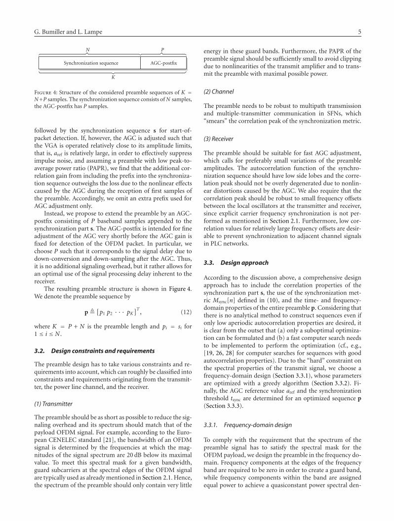
Figure 4: Structure of the considered preamble sequences of K =N+P samples. The synchronization sequence consists of N samples,the AGC-postfix has P samples.
followed by the synchronization sequence s for start-of-packet detection. If, however, the AGC is adjusted such thatthe VGA is operated relatively close to its amplitude limits,that is, aref is relatively large, in order to effectively suppressimpulse noise, and assuming a preamble with low peak-to-average power ratio (PAPR), we find that the additional cor-relation gain from including the prefix into the synchroniza-tion sequence outweighs the loss due to the nonlinear effectscaused by the AGC during the reception of first samples ofthe preamble. Accordingly, we omit an extra prefix used forAGC adjustment only.
Instead, we propose to extend the preamble by an AGC-postfix consisting of P baseband samples appended to thesynchronization part s. The AGC-postfix is intended for fineadjustment of the AGC very shortly before the AGC gain isfixed for detection of the OFDM packet. In particular, wechoose P such that it corresponds to the signal delay due todown-conversion and down-sampling after the AGC. Thus,it is no additional signaling overhead, but it rather allows foran optimal use of the signal processing delay inherent to thereceiver.
The resulting preamble structure is shown in Figure 4.We denote the preamble sequence by
p �[p1 p2 · · · pK
]T, (12)
where K = P + N is the preamble length and pi = si for1 ≤ i ≤ N .
3.2. Design constraints and requirements
The preamble design has to take various constraints and re-quirements into account, which can roughly be classified intoconstraints and requirements originating from the transmit-ter, the power line channel, and the receiver.
(1) Transmitter
The preamble should be as short as possible to reduce the sig-naling overhead and its spectrum should match that of thepayload OFDM signal. For example, according to the Euro-pean CENELEC standard [21], the bandwidth of an OFDMsignal is determined by the frequencies at which the mag-nitudes of the signal spectrum are 20 dB below its maximalvalue. To meet this spectral mask for a given bandwidth,guard subcarriers at the spectral edges of the OFDM signalare typically used as already mentioned in Section 2.1. Hence,the spectrum of the preamble should only contain very little
energy in these guard bands. Furthermore, the PAPR of thepreamble signal should be sufficiently small to avoid clippingdue to nonlinearities of the transmit amplifier and to trans-mit the preamble with maximal possible power.
(2) Channel
The preamble needs to be robust to multipath transmissionand multiple-transmitter communication in SFNs, which“smears” the correlation peak of the synchronization metric.
(3) Receiver
The preamble should be suitable for fast AGC adjustment,which calls for preferably small variations of the preambleamplitudes. The autocorrelation function of the synchro-nization sequence should have low side lobes and the corre-lation peak should not be overly degenerated due to nonlin-ear distortions caused by the AGC. We also require that thecorrelation peak should be robust to small frequency offsetsbetween the local oscillators at the transmitter and receiver,since explicit carrier frequency synchronization is not per-formed as mentioned in Section 2.1. Furthermore, low cor-relation values for relatively large frequency offsets are desir-able to prevent synchronization to adjacent channel signalsin PLC networks.
3.3. Design approach
According to the discussion above, a comprehensive designapproach has to include the correlation properties of thesynchronization part s, the use of the synchronization met-ric Msync[n] defined in (10), and the time- and frequency-domain properties of the entire preamble p. Considering thatthere is no analytical method to construct sequences even ifonly low aperiodic autocorrelation properties are desired, itis clear from the outset that (a) only a suboptimal optimiza-tion can be formulated and (b) a fast computer search needsto be implemented to perform the optimization (cf., e.g.,[19, 26, 28] for computer searches for sequences with goodautocorrelation properties). Due to the “hard” constraint onthe spectral properties of the transmit signal, we choose afrequency-domain design (Section 3.3.1), whose parametersare optimized with a greedy algorithm (Section 3.3.2). Fi-nally, the AGC reference value aref and the synchronizationthreshold tsync are determined for an optimized sequence p(Section 3.3.3).
3.3.1. Frequency-domain design
To comply with the requirement that the spectrum of thepreamble signal has to satisfy the spectral mask for theOFDM payload, we design the preamble in the frequency do-main. Frequency components at the edges of the frequencyband are required to be zero in order to create a guard band,while frequency components within the band are assignedequal power to achieve a quasiconstant power spectral den-

6 EURASIP Journal on Advances in Signal Processing
sity. Hence, denoting the ratio of active subcarriers to allsubcarriers by d, we require that d · K of the K elements
Pv �K∑
i=1
pie− j(2π/K)(i−1)(v−1), 1 ≤ v ≤ K , (13)
of the discrete Fourier transform (DFT) of p have constantmodulus, while the others are zero. More specifically,
Pv =⎧⎪⎨⎪⎩e jφv , for
(1− d)2
K < v ≤ (1 + d)2
K ,
0, otherwise,(14)
which results in the preamble sequence
pi = 1K
(1+d)K/2∑
v=(1−d)K/2+1
e jφv e j(2π/K)(i−1)(v−1). (15)
For the numerical evaluations in Section 4 we will adopt d =0.82 as an exemplary and practically relevant value.1
We would like to mention that a similar approach wasconsidered in [29, 30] for the design of an OFDM synchro-nization sequence. Different from (15), the synchronizationsequence in [29, 30] is embedded in the OFDM data signal,and hence only a subset of active subcarriers (so-called pilotsubcarriers) are available for synchronization. The optimiza-tions were carried out with respect to the positions v of thepilot subcarriers assuming φv = 0.
3.3.2. Optimization
The further optimization of p with elements from (15) isbased on a figure of merit, which incorporates the require-ments on the preamble sequence listed in Section 3.2, and asimple greedy algorithm is employed to search for preambleswith large merit.
(a) Figure of merit
Every trial preamble vector p is passed through the entiretransmitter and receiver chain to generate the correspondingbaseband received signal y[n]. The effects of digital modu-lation and filtering, digital-to-analog (DA) and AD conver-sion and possible clipping are considered by setting the peakvalue of the transmitted preamble signal p(t) equal to themaximum amplitude of the DA converter (DAC) output. Toassess the autocorrelation properties of the synchronization-sequence part of the preamble, the peak-to-side-peak ratios
Rpsp(L) � cpeak(L)
cside-peak(L)(16)
1 This particular choice is inspired by the parameters in iAd’s PLC system[24], where 82% of the OFDM subcarriers are active.
with
cpeak(L) = maxn∈[n0+N−1,
n0+N+L−2]
{ L−1∑
l=0
∣∣∣∣∣
N−1∑
i=0
y[n− l − i]s∗N−i
∣∣∣∣∣
},
(17)
cside-peak(L) = maxn<n0+N−1
{ L−1∑
l=0
∣∣∣∣∣
N−1∑
i=0
y[n− l − i]s∗N−i
∣∣∣∣∣
}
(18)
are determined for Lmin ≤ L ≤ Lmax. Values n > n0 +N+L−2are not considered for side peaks in (18) since a synchro-nization will always lock on to the first correlation peak. Toaccount for the dynamic of the transmitted preamble signalp(t) corresponding to the preamble p, which is critical forthe transmitter and receiver VGA and the AGC adjustmentat the receiver, we consider
D1 �∫ TK
0
∣∣p(t)∣∣dt,
D2 � 5∫ TK
TN
∣∣ p(t)∣∣dt +
∫ TN
0
∣∣ p(t)∣∣dt,
D3 � 3 mint∈(TN ,TK )
{∣∣p(t)∣∣} + min
t∈(0,TN )
{∣∣p(t)∣∣},
(19)
where TK and TN denote the duration of the whole pream-ble and the synchronization part, respectively, and p(t) is thefirst-order derivative of p(t). Since the maximum amplitudeof p(t) is fixed, D1 and D2 are measures for the amplitudefluctuations within p(t). While D1 reflects the absolute vari-ation of the amplitudes, D2 is an indicator for the rate of am-plitude changes. Finally, the occurrence of very small ampli-tude signals, which is important for AGC adjustment, is con-sidered in D3. Since quick amplitude changes and small min-imum amplitudes can have a detrimental effect for the AGCadjustment particularly during the AGC-postfix, the corre-sponding terms are weighted with larger factors in D2 andD3.
Finally, Rpsp(L), D1, D2, and D3 are combined as
F =Lmax∑
L=Lmin
Rpsp(L) + D1 + K ·D3 −D2 (20)
and F is considered as the figure of merit according to whichpreamble sequences are optimized.
We remark that while the requirement for robustnessagainst frequency offset and false synchronization listed inSection 3.2 is not explicitly accounted for in F, we foundthat frequency-domain design with randomly chosen initialphases (see (b) below) yields fairly robust preamble designsin this regard (see numerical results in Section 4.2).
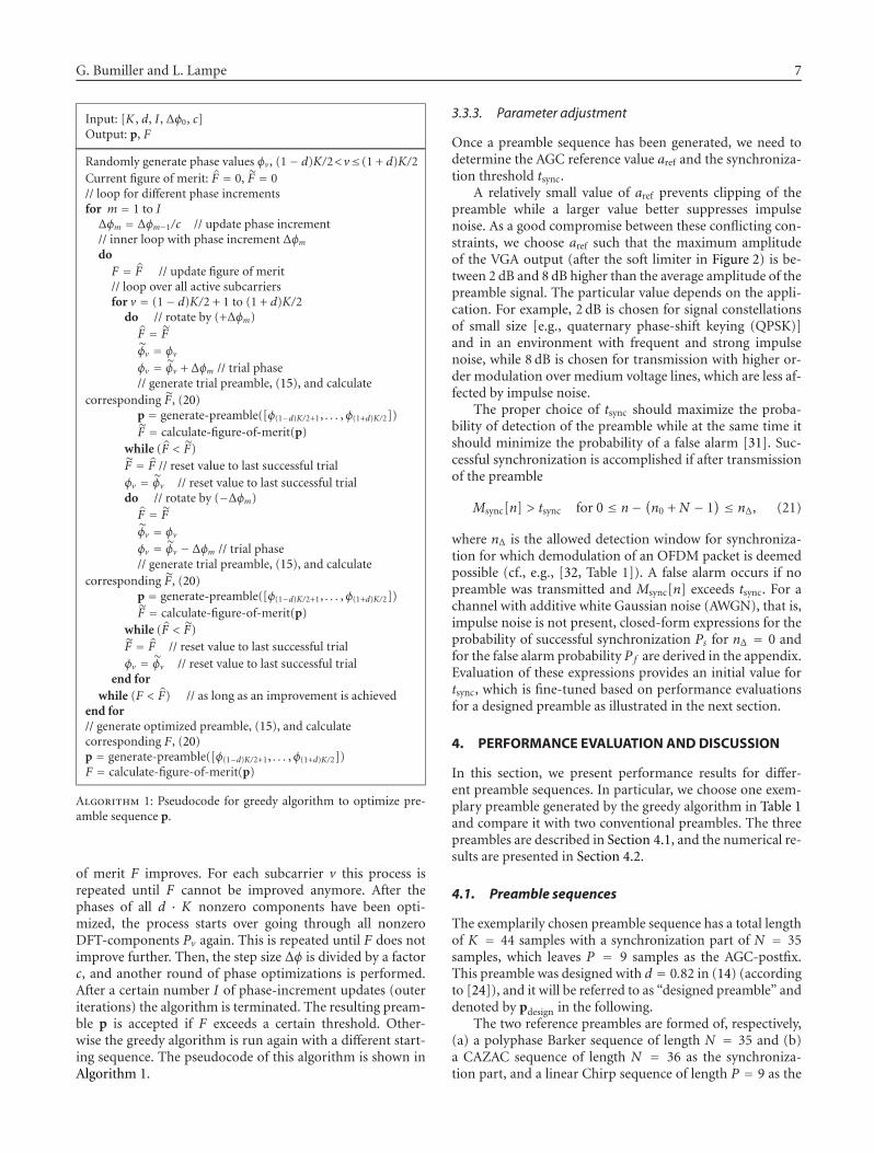
(b) Greedy algorithm
The greedy optimization algorithm starts with a randomlychosen initial DFT-vector and rotates the DFT-componentsPv successively by e± jΔφ and a rotation is retained if the figure
G. Bumiller and L. Lampe 7
Input: [K , d, I , Δφ0, c]Output: p, F
Randomly generate phase values φv , (1− d)K/2<v≤(1 + d)K/2Current figure of merit: F = 0, F = 0// loop for different phase incrementsfor m = 1 to IΔφm = Δφm−1/c // update phase increment// inner loop with phase increment Δφm
doF = F // update figure of merit// loop over all active subcarriersfor v = (1− d)K/2 + 1 to (1 + d)K/2
do // rotate by (+Δφm)F = F
φv = φv
φv = φv + Δφm // trial phase// generate trial preamble, (15), and calculate
corresponding F, (20)p = generate-preamble([φ(1−d)K/2+1, . . . ,φ(1+d)K/2])F = calculate-figure-of-merit(p)
while (F < F)F = F // reset value to last successful trialφv = φv // reset value to last successful trialdo // rotate by (−Δφm)F = F
φv = φv
φv = φv − Δφm // trial phase// generate trial preamble, (15), and calculate
corresponding F, (20)p = generate-preamble([φ(1−d)K/2+1, . . . ,φ(1+d)K/2])F = calculate-figure-of-merit(p)
while (F < F)F = F // reset value to last successful trialφv = φv // reset value to last successful trial
end forwhile (F < F) // as long as an improvement is achieved
end for// generate optimized preamble, (15), and calculatecorresponding F, (20)p = generate-preamble([φ(1−d)K/2+1, . . . ,φ(1+d)K/2])F = calculate-figure-of-merit(p)
Algorithm 1: Pseudocode for greedy algorithm to optimize pre-amble sequence p.
of merit F improves. For each subcarrier v this process isrepeated until F cannot be improved anymore. After thephases of all d · K nonzero components have been opti-mized, the process starts over going through all nonzeroDFT-components Pv again. This is repeated until F does notimprove further. Then, the step size Δφ is divided by a factorc, and another round of phase optimizations is performed.After a certain number I of phase-increment updates (outeriterations) the algorithm is terminated. The resulting pream-ble p is accepted if F exceeds a certain threshold. Other-wise the greedy algorithm is run again with a different start-ing sequence. The pseudocode of this algorithm is shown inAlgorithm 1.
3.3.3. Parameter adjustment
Once a preamble sequence has been generated, we need todetermine the AGC reference value aref and the synchroniza-tion threshold tsync.
A relatively small value of aref prevents clipping of thepreamble while a larger value better suppresses impulsenoise. As a good compromise between these conflicting con-straints, we choose aref such that the maximum amplitudeof the VGA output (after the soft limiter in Figure 2) is be-tween 2 dB and 8 dB higher than the average amplitude of thepreamble signal. The particular value depends on the appli-cation. For example, 2 dB is chosen for signal constellationsof small size [e.g., quaternary phase-shift keying (QPSK)]and in an environment with frequent and strong impulsenoise, while 8 dB is chosen for transmission with higher or-der modulation over medium voltage lines, which are less af-fected by impulse noise.
The proper choice of tsync should maximize the proba-bility of detection of the preamble while at the same time itshould minimize the probability of a false alarm [31]. Suc-cessful synchronization is accomplished if after transmissionof the preamble
Msync[n] > tsync for 0 ≤ n− (n0 + N − 1) ≤ nΔ, (21)
where nΔ is the allowed detection window for synchroniza-tion for which demodulation of an OFDM packet is deemedpossible (cf., e.g., [32, Table 1]). A false alarm occurs if nopreamble was transmitted and Msync[n] exceeds tsync. For achannel with additive white Gaussian noise (AWGN), that is,impulse noise is not present, closed-form expressions for theprobability of successful synchronization Ps for nΔ = 0 andfor the false alarm probability Pf are derived in the appendix.Evaluation of these expressions provides an initial value fortsync, which is fine-tuned based on performance evaluationsfor a designed preamble as illustrated in the next section.
4. PERFORMANCE EVALUATION AND DISCUSSION
In this section, we present performance results for differ-ent preamble sequences. In particular, we choose one exem-plary preamble generated by the greedy algorithm in Table 1and compare it with two conventional preambles. The threepreambles are described in Section 4.1, and the numerical re-sults are presented in Section 4.2.
4.1. Preamble sequences
The exemplarily chosen preamble sequence has a total lengthof K = 44 samples with a synchronization part of N = 35samples, which leaves P = 9 samples as the AGC-postfix.This preamble was designed with d = 0.82 in (14) (accordingto [24]), and it will be referred to as “designed preamble” anddenoted by pdesign in the following.
The two reference preambles are formed of, respectively,(a) a polyphase Barker sequence of length N = 35 and (b)a CAZAC sequence of length N = 36 as the synchroniza-tion part, and a linear Chirp sequence of length P = 9 as the
8 EURASIP Journal on Advances in Signal Processing
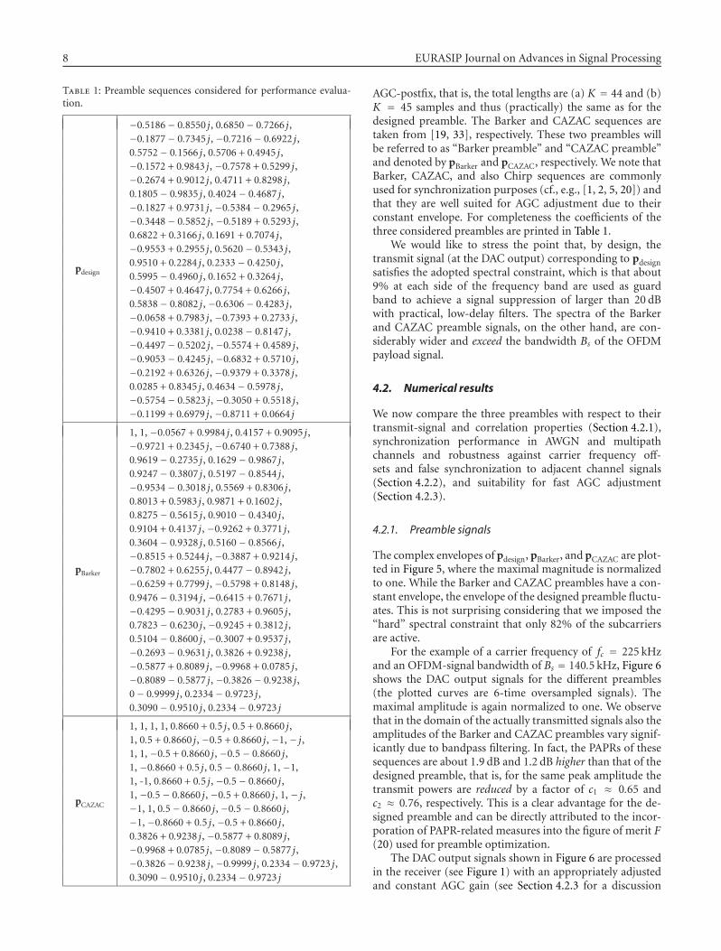
Table 1: Preamble sequences considered for performance evalua-tion.
pdesign
−0.5186− 0.8550 j, 0.6850− 0.7266 j,−0.1877− 0.7345 j, −0.7216− 0.6922 j,0.5752− 0.1566 j, 0.5706 + 0.4945 j,−0.1572 + 0.9843 j, −0.7578 + 0.5299 j,−0.2674 + 0.9012 j, 0.4711 + 0.8298 j,0.1805− 0.9835 j, 0.4024− 0.4687 j,−0.1827 + 0.9731 j, −0.5384− 0.2965 j,−0.3448− 0.5852 j, −0.5189 + 0.5293 j,0.6822 + 0.3166 j, 0.1691 + 0.7074 j,−0.9553 + 0.2955 j, 0.5620− 0.5343 j,0.9510 + 0.2284 j, 0.2333− 0.4250 j,0.5995− 0.4960 j, 0.1652 + 0.3264 j,−0.4507 + 0.4647 j, 0.7754 + 0.6266 j,0.5838− 0.8082 j, −0.6306− 0.4283 j,−0.0658 + 0.7983 j, −0.7393 + 0.2733 j,−0.9410 + 0.3381 j, 0.0238− 0.8147 j,−0.4497− 0.5202 j, −0.5574 + 0.4589 j,−0.9053− 0.4245 j, −0.6832 + 0.5710 j,−0.2192 + 0.6326 j, −0.9379 + 0.3378 j,0.0285 + 0.8345 j, 0.4634− 0.5978 j,−0.5754− 0.5823 j, −0.3050 + 0.5518 j,−0.1199 + 0.6979 j, −0.8711 + 0.0664 j
pBarker
1, 1, −0.0567 + 0.9984 j, 0.4157 + 0.9095 j,−0.9721 + 0.2345 j, −0.6740 + 0.7388 j,0.9619− 0.2735 j, 0.1629− 0.9867 j,0.9247− 0.3807 j, 0.5197− 0.8544 j,−0.9534− 0.3018 j, 0.5569 + 0.8306 j,0.8013 + 0.5983 j, 0.9871 + 0.1602 j,0.8275− 0.5615 j, 0.9010− 0.4340 j,0.9104 + 0.4137 j, −0.9262 + 0.3771 j,0.3604− 0.9328 j, 0.5160− 0.8566 j,−0.8515 + 0.5244 j, −0.3887 + 0.9214 j,−0.7802 + 0.6255 j, 0.4477− 0.8942 j,−0.6259 + 0.7799 j, −0.5798 + 0.8148 j,0.9476− 0.3194 j, −0.6415 + 0.7671 j,−0.4295− 0.9031 j, 0.2783 + 0.9605 j,0.7823− 0.6230 j, −0.9245 + 0.3812 j,0.5104− 0.8600 j, −0.3007 + 0.9537 j,−0.2693− 0.9631 j, 0.3826 + 0.9238 j,−0.5877 + 0.8089 j, −0.9968 + 0.0785 j,−0.8089− 0.5877 j, −0.3826− 0.9238 j,0− 0.9999 j, 0.2334− 0.9723 j,0.3090− 0.9510 j, 0.2334− 0.9723 j
pCAZAC
1, 1, 1, 1, 0.8660 + 0.5 j, 0.5 + 0.8660 j,1, 0.5 + 0.8660 j, −0.5 + 0.8660 j, −1, − j,1, 1, −0.5 + 0.8660 j, −0.5− 0.8660 j,1, −0.8660 + 0.5 j, 0.5− 0.8660 j, 1, −1,1, -1, 0.8660 + 0.5 j, −0.5− 0.8660 j,1, −0.5− 0.8660 j, −0.5 + 0.8660 j, 1, − j,−1, 1, 0.5− 0.8660 j, −0.5− 0.8660 j,−1, −0.8660 + 0.5 j, −0.5 + 0.8660 j,0.3826 + 0.9238 j, −0.5877 + 0.8089 j,−0.9968 + 0.0785 j, −0.8089− 0.5877 j,−0.3826− 0.9238 j, −0.9999 j, 0.2334− 0.9723 j,0.3090− 0.9510 j, 0.2334− 0.9723 j
AGC-postfix, that is, the total lengths are (a) K = 44 and (b)K = 45 samples and thus (practically) the same as for thedesigned preamble. The Barker and CAZAC sequences aretaken from [19, 33], respectively. These two preambles willbe referred to as “Barker preamble” and “CAZAC preamble”and denoted by pBarker and pCAZAC, respectively. We note thatBarker, CAZAC, and also Chirp sequences are commonlyused for synchronization purposes (cf., e.g., [1, 2, 5, 20]) andthat they are well suited for AGC adjustment due to theirconstant envelope. For completeness the coefficients of thethree considered preambles are printed in Table 1.
We would like to stress the point that, by design, thetransmit signal (at the DAC output) corresponding to pdesignsatisfies the adopted spectral constraint, which is that about9% at each side of the frequency band are used as guardband to achieve a signal suppression of larger than 20 dBwith practical, low-delay filters. The spectra of the Barkerand CAZAC preamble signals, on the other hand, are con-siderably wider and exceed the bandwidth Bs of the OFDMpayload signal.
4.2. Numerical results
We now compare the three preambles with respect to theirtransmit-signal and correlation properties (Section 4.2.1),synchronization performance in AWGN and multipathchannels and robustness against carrier frequency off-sets and false synchronization to adjacent channel signals(Section 4.2.2), and suitability for fast AGC adjustment(Section 4.2.3).
4.2.1. Preamble signals
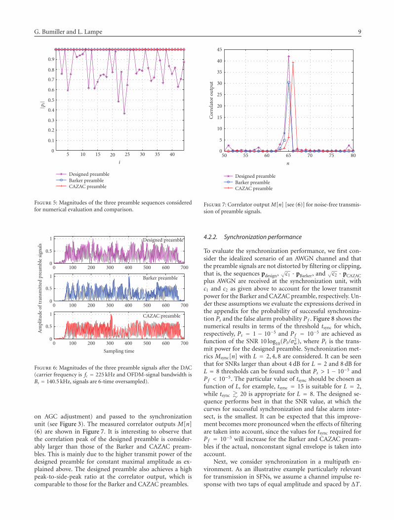
The complex envelopes of pdesign, pBarker, and pCAZAC are plot-ted in Figure 5, where the maximal magnitude is normalizedto one. While the Barker and CAZAC preambles have a con-stant envelope, the envelope of the designed preamble fluctu-ates. This is not surprising considering that we imposed the“hard” spectral constraint that only 82% of the subcarriersare active.
For the example of a carrier frequency of fc = 225 kHzand an OFDM-signal bandwidth of Bs = 140.5 kHz, Figure 6shows the DAC output signals for the different preambles(the plotted curves are 6-time oversampled signals). Themaximal amplitude is again normalized to one. We observethat in the domain of the actually transmitted signals also theamplitudes of the Barker and CAZAC preambles vary signif-icantly due to bandpass filtering. In fact, the PAPRs of thesesequences are about 1.9 dB and 1.2 dB higher than that of thedesigned preamble, that is, for the same peak amplitude thetransmit powers are reduced by a factor of c1 ≈ 0.65 andc2 ≈ 0.76, respectively. This is a clear advantage for the de-signed preamble and can be directly attributed to the incor-poration of PAPR-related measures into the figure of merit F(20) used for preamble optimization.
The DAC output signals shown in Figure 6 are processedin the receiver (see Figure 1) with an appropriately adjustedand constant AGC gain (see Section 4.2.3 for a discussion
G. Bumiller and L. Lampe 9
5 10 15 20 25 30 35 40
i
0
0.1
0.2
0.3
0.4
0.5
0.6
0.7
0.8
0.9
|pi|
Designed preambleBarker preambleCAZAC preamble
Figure 5: Magnitudes of the three preamble sequences consideredfor numerical evaluation and comparison.
Am
plit
ude
oftr
ansm
itte
dpr
eam
ble
sign
als
Sampling time
Designed preamble
Barker preamble
CAZAC preamble
0 100 200 300 400 500 600 700
0 100 200 300 400 500 600 700
0 100 200 300 400 500 600 700
0
0.5
1
0
0.5
1
0
0.5
1
Figure 6: Magnitudes of the three preamble signals after the DAC(carrier frequency is fc = 225 kHz and OFDM-signal bandwidth isBs = 140.5 kHz, signals are 6-time oversampled).
on AGC adjustment) and passed to the synchronizationunit (see Figure 3). The measured correlator outputs M[n](6) are shown in Figure 7. It is interesting to observe thatthe correlation peak of the designed preamble is consider-ably larger than those of the Barker and CAZAC pream-bles. This is mainly due to the higher transmit power of thedesigned preamble for constant maximal amplitude as ex-plained above. The designed preamble also achieves a highpeak-to-side-peak ratio at the correlator output, which iscomparable to those for the Barker and CAZAC preambles.
50 55 60 65 70 75 800
5
10
15
20
25
30
35
40
45
n
Cor
rela
tor
outp
ut
Designed preambleBarker preambleCAZAC preamble
Figure 7: Correlator output M[n] [see (6)] for noise-free transmis-sion of preamble signals.
4.2.2. Synchronization performance
To evaluate the synchronization performance, we first con-sider the idealized scenario of an AWGN channel and thatthe preamble signals are not distorted by filtering or clipping,that is, the sequences pdesign,
√c1 · pBarker, and
√c2 · pCAZAC
plus AWGN are received at the synchronization unit, withc1 and c2 as given above to account for the lower transmitpower for the Barker and CAZAC preamble, respectively. Un-der these assumptions we evaluate the expressions derived inthe appendix for the probability of successful synchroniza-tion Ps and the false alarm probability Pf . Figure 8 shows thenumerical results in terms of the threshold tsync for which,respectively, Ps = 1 − 10−5 and Pf = 10−5 are achieved asfunction of the SNR 10 log10(Pt/σ2
w), where Pt is the trans-mit power for the designed preamble. Synchronization met-rics Msync[n] with L = 2, 4, 8 are considered. It can be seenthat for SNRs larger than about 4 dB for L = 2 and 8 dB forL = 8 thresholds can be found such that Ps > 1 − 10−5 andPf < 10−5. The particular value of tsync should be chosen asfunction of L, for example, tsync = 15 is suitable for L = 2,while tsync � 20 is appropriate for L = 8. The designed se-quence performs best in that the SNR value, at which thecurves for successful synchronization and false alarm inter-sect, is the smallest. It can be expected that this improve-ment becomes more pronounced when the effects of filteringare taken into account, since the values for tsync required forPf = 10−5 will increase for the Barker and CAZAC pream-bles if the actual, nonconstant signal envelope is taken intoaccount.
Next, we consider synchronization in a multipath en-vironment. As an illustrative example particularly relevantfor transmission in SFNs, we assume a channel impulse re-sponse with two taps of equal amplitude and spaced by ΔT .

10 EURASIP Journal on Advances in Signal Processing
Ps = 1− 10−5
L = 2
P f = 10−5
0
5
10
15
20
25
30
−5 0 5 10 15
t syn
csu
chth
atPs=
1−
10−5
orPf=
10−5
10 log10(Pt/σ2w)
Barker preambleCAZAC preambleDesigned preamble
15
Ps = 1− 10−5
L = 4
P f = 10−5
0
5
10
15
20
25
30
−5 0 5 10 15
t syn
csu
chth
atPs=
1−
10−5
orPf=
10−5
10 log10(Pt/σ2w)
Barker preambleCAZAC preambleDesigned preamble
Ps = 1− 10−5
L = 8
P f = 10−5
0
5
10
15
20
25
30
−5 0 5 10 15
t syn
csu
chth
atPs=
1−
10−5
orPf=
10−5
10 log10(Pt/σ2w)
Barker preambleCAZAC preambleDesigned preamble
Figure 8: Threshold tsync as function of SNR 10 log10(Pt/σ2w). tsync is adjusted such that Ps = Pr{Msync[n0 + N − 1] > tsync} = 1 − 10−5 if
preamble was sent and Pf = Pr{Msync[n] > tsync} = 10−5 if no preamble was sent, respectively. Analytical results (see the appendix).
The phases of the two taps are rotated to each other by 0,π/2, π, and 3π/2 as sample values for possible phase differ-ences. The preambles are transmitted through such a channeland processed at the receiver assuming an appropriately ad-justed AGC with constant gain. In the synchronization unit,the metric Msync[n] with L = 2, . . . , 8 is evaluated, and theallowed detection window for synchronization is chosen asnΔ = L − 1. Figure 9 shows the maximal values Min andMout of Msync[n] for n falling inside this window, that is,n0 +N −1 ≤ n < n0 +N +nΔ and for n outside2 this window,that is, n < n0 + N − 1, respectively, as function of ΔT fs forall three preambles. For clarity, noise-free transmission is as-sumed. We observe that the full channel energy (equally dis-tributed over the two taps) can be captured with increasing L,that is, Min reaches large values also for 0 ≤ ΔT fs ≤ L, whichconfirms the suitability of the devised synchronization met-ric Msync[n] for multipath channels. We further observe that
Min is always larger than Mout, which is a necessary require-ment for successful synchronization since noise-free trans-mission is assumed. However, the margin between Min andMout is noticeably improved for the designed preamble whencompared to the Barker and CAZAC preambles. Hence, weconclude that the designed preamble is advantageous for syn-chronization in a multipath environment. Again, we can at-tribute this improvement to the preamble design as devised
2 It should be noted that the synchronization will always lock on to the firstn for which Msync[n] > tsync. Therefore, we do not consider maxima ofMsync[n] for n ≥ n0 + N + nΔ.
in Section 3.3, which explicitly considers synchronization inmultipath channels and correlation with L > 1.
To assess the robustness of synchronization against car-rier frequency offset, Figure 10 shows the threshold tsync forwhich Ps = 1− 10−5 is achieved as a function of the normal-ized offset Δ fc/ fs and for synchronization with L = 2, 4, 8.The numerical results are obtained from the expressions pre-sented in the appendix and the same set up as in Figure 8is applied, and the SNR is chosen as 10 log10(Pt/σ2
w) =10 dB. For clarity, only the designed preamble and the Barkerpreamble are considered. We observe that, for both pream-bles, the degradation of the synchronization threshold isfairly moderate for |Δ fc/ fs| < 0.002 and becomes moresignificant with increasing frequency offset, especially forsmaller values of L. Since |Δ fc/ fs| = 0.002 corresponds toa maximal absolute offset of about ±30 Hz considering thesmallest sampling rate of about fs = 15 kHz, and since thehighest possible carrier frequency is about fc = 0.5 MHz, alocal oscillator offset of 60 ppm would be acceptable. This isa much less stringent requirement on the local oscillator sta-bility than those imposed by the OFDM transmission system.Thus, we conclude that the potential carrier frequency offsetsare well coped with by the devised synchronization method.
Finally, the robustness against false synchronization inthe presence of adjacent channel signals is considered. Itshould be noted that for the large dynamic of, say, 120 dBof AGC and ADC required in PLC systems, the typical atten-uation of about, say, 60 dB of adjacent channel signals is notsufficient to prevent false synchronization. As exemplary sys-tem parameters, we choose a transmitter carrier frequency

G. Bumiller and L. Lampe 11
Min
andM
out
Min
andM
out
Min
andM
out
Min
andM
out
Min
andM
out
Min
andM
out
Min
andM
out
0
20
40
0
20
40
0
20
40
0
20
40
0
20
40
0
20
40
0
20
40
0 5 10
0 5 10
0 5 10
0 5 10
0 5 10
0 5 10
0 5 10
ΔT fs
L = 5
L = 8
L = 7
L = 6
L = 4
L = 3
L = 2
Designed preamble
Min
andM
out
Min
andM
out
Min
andM
out
Min
andM
out
Min
andM
out
Min
andM
out
Min
andM
out
0
20
40
0
20
40
0
20
40
0
20
40
0
20
40
0
20
40
0
20
40
0 5 10
0 5 10
0 5 10
0 5 10
0 5 10
0 5 10
0 5 10
ΔT fs
L = 5
L = 8
L = 7
L = 6
L = 4
L = 3
L = 2
Barker preamble
Min
andM
out
Min
andM
out
Min
andM
out
Min
andM
out
Min
andM
out
Min
andM
out
Min
andM
out
0
20
40
0
20
40
0
20
40
0
20
40
0
20
40
0
20
40
0
20
40
0 5 10
0 5 10
0 5 10
0 5 10
0 5 10
0 5 10
0 5 10
ΔT fs
L = 5
L = 8
L = 7
L = 6
L = 4
L = 3
L = 2
CAZAC preamble
Figure 9: Msync[n] as function of ΔT fs for a noise-free multipath channel with two paths spaced by ΔT and with phase offsets of[0,π/2,π, 3π/2]. Top four curves in each graph: n0 + N − 1 ≤ n < n0 + N + L − 1. Bottom four curves in each graph: n < n0 + N − 1.From top to bottom: L = 2, . . . , 8. From left to right: designed preamble, Barker preamble, and CAZAC preamble. Simulation results.
of fc = 230 kHz and an OFDM-system bandwidth of Bs =60.4 kHz. The receiver carrier frequency is fc + Δ fc with avariable offset of −230 kHz < Δ fc < 270 kHz to cover the en-tire frequency band. The AGC gain is held constant and L = 8is considered, since we found the strongest effects of falsesynchronization for larger correlation windows. In Figure 11,we show the value of Msync[n] for the actual synchronizationtime n0 + N − 1 ≤ n < n0 + N + L − 1 (solid lines) and forn < n0 + N − 1 (dashed lines), that is, too early synchroniza-tion, for all three preambles. Of course, synchronization toan adjacent channel signal is always unwanted, regardless ofwhether the synchronization locks on to the correct point intime or not. We observe that the designed preamble is con-siderably more robust against false synchronization. For bothBarker and CAZAC preamble large metrics Msync[n] occur
for |Δ fc| > 0. In case of the CAZAC preamble the ambiguitiesare a result of its linear Chirp-like structure (cf. [34] and thedesign tool [33]). The designed sequence shows the best per-formance because of the randomly chosen initial phases ofits DFT coefficients, which renders a systematic dependencybetween these coefficients unlikely.
4.2.3. AGC adjustment
Due to its dynamic gain at the beginning of a received pream-ble signal, the AGC influences the synchronization perfor-mance. We found in various simulations of synchronizationwith active AGC that the effect of the nonlinearities on thecorrelation gain is quite similar for the different preamblesand not severe in case of an appropriately adjusted AGC

12 EURASIP Journal on Advances in Signal Processing
14
16
18
20
22
24
26
28
30
−1 −0.8 −0.6 −0.4 −0.2 0 0.2 0.4 0.6 0.8 1
×10−2
L = 2
L = 4
L = 8
t syn
csu
chth
atPs=
1−
10−5
Δ fc/ fs
Barker preambleDesigned preamble
Figure 10: Threshold tsync as function of normalized frequency off-set Δ f / fs for 10 log10(Pt/σ2
w) = 10 dB. tsync is adjusted such thatPs = Pr{Msync[n0 + N − 1] > tsync} = 1 − 10−5 if preamble wassent for L = 2, 4, 8. Analytical results.
speed. We therefore concentrate on the suitability of thepreamble signals for AGC adjustment. A preamble is deemedsuitable if the AGC gain converges fast to a final value withlittle fluctuation before reaching this value in order to allowfor sufficient averaging (I-circuit) of noise effects.
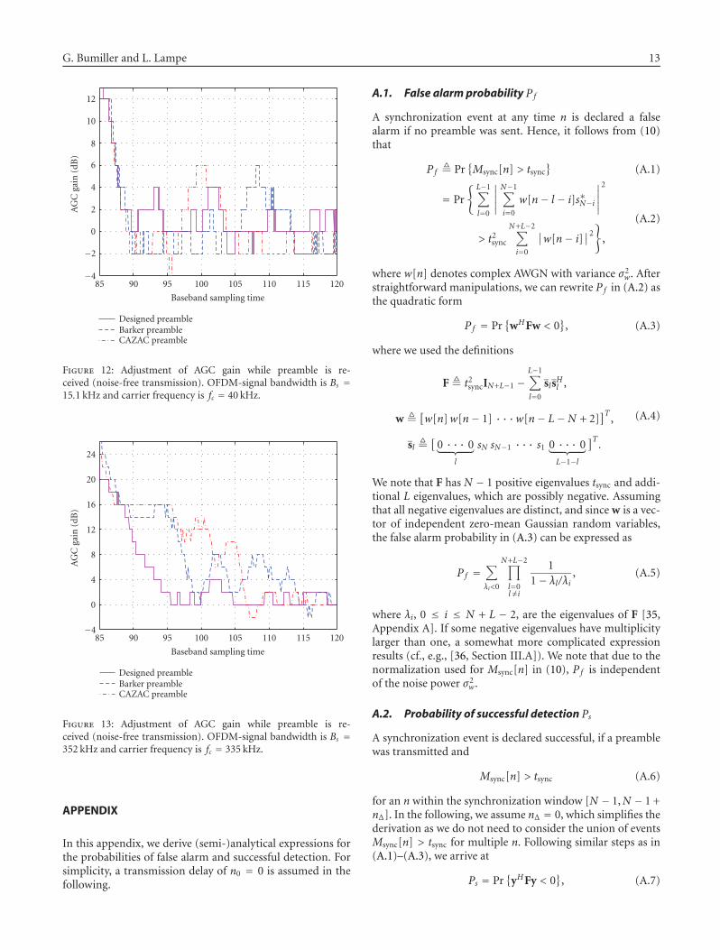
Figures 12 and 13 illustrate the adjustment of the AGCgain for a relatively narrow OFDM-signal bandwidth of Bs =15.1 kHz (Figure 12) and a relatively high bandwidth of Bs =352 kHz (Figure 13). The step size of gain of the VGA is 2 dBand the moving-average parameter [see (1)] is NAGC = 64for the narrowband signal and NAGC = 32 for the wide-band signal. The maximal ADC output corresponds to a unitamplitude, and aref = 0.4 is adjusted (see Figure 2), which,for example, corresponds to an about 5 dB margin betweenmaximal and effective value of a sine signal. The preamblesare received without noise and preceded by an all-zero se-quence of 70 samples. Taking filter delay time into accounta constant AGC gain should be reached after between 111and 119 received samples. It can be seen that, for both signalbandwidths, the designed preamble leads to a considerablyfaster and more stable gain adjustment than the Barker andCAZAC preambles. Especially the Barker preamble causeslarge variations of up to 8 dB of the AGC gain in the crit-ical range between 111 to 119 samples. This is not accept-able considering that the difference between maximal andaverage amplitude after the soft limiter (see Figure 2) shouldbe not more than 8 dB in order to suppress impulse noise.We conclude that the devised optimization of the pream-ble, taking requirements for AGC adjustment into account,has resulted in an improved performance also in this re-spect.
−200 −150 −100 −50 0 50 100 150 200 2500
10203040
Msy
nc[n
]
Δ fc (kHz)
Designed preamble
−200 −150 −100 −50 0 50 100 150 200 2500
10203040
Msy
nc[n
]
Δ fc (kHz)
Barker preamble
−200 −150 −100 −50 0 50 100 150 200 2500
10203040
Msy
nc[n
]Δ fc (kHz)
CAZAC preamble
Figure 11: Msync[n] for n0 +N −1 ≤ n < n0 +N +L−1 (solid lines)and for n < N + n0 − 1 (dashed lines) when preamble signal wassent with a frequency offset Δ fc. Carrier frequency fc = 230 kHz,OFDM-signal bandwidth Bs = 60.4 kHz, noise-free channel, andsynchronization with L = 8. Simulation results.
5. CONCLUSIONS
In this paper, we have presented a comprehensive approachfor the design of preamble sequences for fast burst syn-chronization in PLC systems. We have concentrated on sys-tems operating below 500 kHz with data rates not exceed-ing 500 kbps (which are typical for various network ap-plications), for which carrier and sampling frequency syn-chronization are not necessary. The proposed optimizationmethod takes important practical requirements, in particu-lar the need for spectral shaping and for fast AGC adjust-ment, into account. The most prominent properties of thepower line channel, which are multipath propagation, highlyvarying path loss, and disturbance by impulse noise, are ex-plicitly accounted for through the devised AGC structure andthe novel synchronization metric. We have also devised asuboptimal stochastic optimization algorithm to efficientlysearch for preamble sequences which maximize the devel-oped figure of merit. An extensive performance compari-son of a newly designed and two conventional preamble se-quences has shown that the designed sequence yields the bestresults both in terms of synchronization in various transmis-sion environments and in terms of AGC adjustment. Thuswe believe that the presented framework is particularly use-ful for system engineers looking for an in-(m)any-respect(s)good solution.
G. Bumiller and L. Lampe 13
85 90 95 100 105 110 115 120
Baseband sampling time
−4
−2
0
2
4
6
8
10
12
AG
Cga
in(d
B)
Designed preambleBarker preambleCAZAC preamble
Figure 12: Adjustment of AGC gain while preamble is re-ceived (noise-free transmission). OFDM-signal bandwidth is Bs =15.1 kHz and carrier frequency is fc = 40 kHz.
85 90 95 100 105 110 115 120
Baseband sampling time
−4
0
4
8
12
16
20
24
AG
Cga
in(d
B)
Designed preambleBarker preambleCAZAC preamble
Figure 13: Adjustment of AGC gain while preamble is re-ceived (noise-free transmission). OFDM-signal bandwidth is Bs =352 kHz and carrier frequency is fc = 335 kHz.
APPENDIX
In this appendix, we derive (semi-)analytical expressions forthe probabilities of false alarm and successful detection. Forsimplicity, a transmission delay of n0 = 0 is assumed in thefollowing.
A.1. False alarm probability Pf
A synchronization event at any time n is declared a falsealarm if no preamble was sent. Hence, it follows from (10)that
Pf � Pr{Msync[n] > tsync
}(A.1)
= Pr
{ L−1∑
l=0
∣∣∣∣∣
N−1∑
i=0
w[n− l − i]s∗N−i
∣∣∣∣∣
2
> t2sync
N+L−2∑
i=0
∣∣w[n− i]∣∣2}
,
(A.2)
where w[n] denotes complex AWGN with variance σ2w. After
straightforward manipulations, we can rewrite Pf in (A.2) asthe quadratic form
Pf = Pr{
wHFw < 0}
, (A.3)
where we used the definitions
F � t2syncIN+L−1 −
L−1∑
l=0
slsHl ,
w �[w[n]w[n− 1] · · ·w[n− L−N + 2]
]T,
sl �[
0 · · · 0︸ ︷︷ ︸l
sN sN−1 · · · s1 0 · · · 0︸ ︷︷ ︸L−1−l
]T.
(A.4)
We note that F has N − 1 positive eigenvalues tsync and addi-tional L eigenvalues, which are possibly negative. Assumingthat all negative eigenvalues are distinct, and since w is a vec-tor of independent zero-mean Gaussian random variables,the false alarm probability in (A.3) can be expressed as
Pf =∑
λi<0
N+L−2∏
l=0l /=i
11− λl/λi
, (A.5)
where λi, 0 ≤ i ≤ N + L − 2, are the eigenvalues of F [35,Appendix A]. If some negative eigenvalues have multiplicitylarger than one, a somewhat more complicated expressionresults (cf., e.g., [36, Section III.A]). We note that due to thenormalization used for Msync[n] in (10), Pf is independentof the noise power σ2
w.
A.2. Probability of successful detection Ps
A synchronization event is declared successful, if a preamblewas transmitted and
Msync[n] > tsync (A.6)
for an n within the synchronization window [N − 1,N − 1 +nΔ]. In the following, we assume nΔ = 0, which simplifies thederivation as we do not need to consider the union of eventsMsync[n] > tsync for multiple n. Following similar steps as in(A.1)–(A.3), we arrive at
Ps = Pr{
yHFy < 0}
, (A.7)

14 EURASIP Journal on Advances in Signal Processing
where
y[n] = f (p,n) + w[n],
y �[y[n] y[n− 1] · · · y[n− L−N + 2]
]T,
(A.8)
and f (p,n) is assumed to be a linear function of the pream-ble p, which depends on the transmission channel. For ex-ample, f (p,n) = pn+1, 0 ≤ n < K and zero otherwise, for anAWGN channel. It is also straightforward to take multipathtransmission and a carrier frequency offset into account. Weobserve that y is a vector of independent Gaussian randomvariables with mean
y �[f (p,n) f (p,n− 1) · · · f (p,n− L−N + 2)
]T
(A.9)
and autocorrelation matrix σ2wIN+L−1.
Following the exposition in [37, Appendix B], we can ex-press Ps as
Ps = 12π j
∫ α+ j∞
α− j∞Φ(s)s
ds, (A.10)
where
Φ(s) = exp(− syH
(F−1 + sIN+L−1σ2
w
)−1y)
det(
IN+L−1 + sσ2wF) (A.11)
and α > 0 lies in the region of convergence of Φ(s). Due tothe essential singularities of Φ(s) originating from the expo-nential term, we choose to numerically evaluate (A.10) usinga Gauss-Chebyshev quadrature rule with q nodes [38]
Ps = 1q
q/2∑
i=1
[R{Φ(α + jατi
)}+ τi�
{Φ(α + jατi
)}]+ Eq,
(A.12)
where τi = tan[(2i − 1)π/(2q)] and the error term Eq be-comes negligible for reasonably large q (of the order of a fewhundreds).
ACKNOWLEDGMENTS
The work in this paper was presented in part at the 2007 IEEEInternational Symposium on Power Line Communicationsand Its Applications (ISPLC), Pisa, Italy, March 26–28, 2007.The work of Lutz Lampe was supported in part by the Na-tional Sciences and Engineering Research Council (NSERC)of Canada.
REFERENCES
[1] J. Massey, “Optimum frame synchronization,” IEEE Transac-tions on Communications, vol. 20, no. 2, pp. 115–119, 1972.
[2] R. Scholtz, “Frame synchronization techniques,” IEEE Trans-actions on Communications, vol. 28, no. 8, part 2, pp. 1204–1213, 1980.
[3] S. A. Fechtel and H. Meyr, “Fast frame synchronization, fre-quency offset estimation and channel acquisition for spon-taneous transmission over unknown frequency-selective ra-dio channels,” in Proceedings of IEEE International Sympo-sium on Personal, Indoor and Mobile Radio Communications(PIMRC ’93), pp. 229–233, Yokohama, Japan, September1993.
[4] IEEE 802.11a, “Wireless LAN Medium Access Control (MAC)and Physical Layer (PHY) Specifications: High-Speed PhysicalLayer in the 5 GHz Band,” 1999.
[5] IEEE 802.15.3, “Wireless Medium Access Control (MAC) andPhysical Layer (PHY) Specifications for High Rate WirelessPANs,” 2003.
[6] M. K. Lee, R. E. Newman, H. A. Latchman, S. Katar, andL. Yonge, “HomePlug 1.0 powerline communication LANs—protocol description and performance results,” InternationalJournal of Communication Systems, vol. 16, no. 5, pp. 447–473,2003.
[7] S. Muller-Weinfurtner, OFDM for Wireless Communications:Nyquist Windowing, Peak-Power Reduction, and Synchroniza-tion, Shaker, Aachen, Germany, 2000.
[8] N. Pavlidou, A. J. Han Vinck, J. Yazdani, and B. Honary,“Power line communications: state of the art and futuretrends,” IEEE Communications Magazine, vol. 41, no. 4, pp.34–40, 2003.
[9] G. Bumiller, T. Sauter, G. Pratl, and A. Treytl, “Secure and reli-able wide-area power-line communication for soft-real-timeapplications within REMPLI,” in Proceedings of the 9th In-ternational Symposium on Power Line Communications andIts Applications (ISPLC ’05), pp. 57–60, Vancouver, BritishColumbia, Canada, April 2005.
[10] M. H. Shwehdi and A. Z. Khan, “A power line data commu-nication interface using spread spectrum technology in homeautomation,” IEEE Transactions on Power Delivery, vol. 11,no. 3, pp. 1232–1237, 1996.
[11] P. van Rensburg and H. Ferreira, “Automotive power-linecommunications: favourable topology for future automotiveelectronic trends,” in Proceedings of the 7th International Sym-posium on Power-Line Communications and Its Applications(ISPLC ’03), pp. 103–108, Kyoto, Japan, March 2003.
[12] M. Zimmermann and K. Dostert, “A multipath model for thepowerline channel,” IEEE Transactions on Communications,vol. 50, no. 4, pp. 553–559, 2002.
[13] M. Eriksson, “Dynamic single frequency networks,” IEEE Jour-nal on Selected Areas in Communications, vol. 19, no. 10, pp.1905–1914, 2001.
[14] G. Bumiller, “Single frequency network technology formedium access and network management,” in Proceedings ofthe 6th International Symposium on Power-Line Communica-tions and Its Applications (ISPLC ’02), Athens, Greece, March2002.
[15] F. J. C. Corripio, J. A. C. Arrabal, L. D. Del Rıo, and J. T. E.Munoz, “Analysis of the cyclic short-term variation of indoorpower line channels,” IEEE Journal on Selected Areas in Com-munications, vol. 24, no. 7, pp. 1327–1338, 2006.
[16] S. Barmada, A. Musolino, and M. Raugi, “Innovative modelfor time-varying power line communication channel responseevaluation,” IEEE Journal on Selected Areas in Communications,vol. 24, no. 7, pp. 1317–1325, 2006.
[17] M. Zimmermann and K. Dostert, “Analysis and modeling ofimpulsive noise in broad-band powerline communications,”IEEE Transactions on Electromagnetic Compatibility, vol. 44,no. 1, pp. 249–258, 2002.

G. Bumiller and L. Lampe 15
[18] S. Golomb and R. Scholtz, “Generalized Barker sequences,”IEEE Transactions on Information Theory, vol. 11, no. 4, pp.533–537, 1965.
[19] M. Friese, “Polyphase Barker sequences up to length 36,” IEEETransactions on Information Theory, vol. 42, no. 4, pp. 1248–1250, 1996.
[20] A. Milewski, “Periodic sequences with optimal properties forchannel estimation and fast start-up equalization,” IBM Jour-nal of Research and Development, vol. 27, no. 5, pp. 426–431,1983.
[21] European Committee for Electrotechnical Standardization(CENELEC), “EN 50065-1: Signaling on Low-Voltage Electri-cal Installations in the Frequency Range 3 kHz-148.5 kHz,”2001.
[22] Association of Radio Industries and Businesses (ARIB), “STD-T84: Power Line Communication Equipment (10 kHz-450kHz)”, 2002.
[23] Federal Communication Commission (FCC), “ET Docket 04-37, FCC 04-245,” October 2004.
[24] G. Bumiller and M. Deinzer, “Narrow band power-line chipsetfor telecommunication and Internet application,” in Proceed-ings of the 5th International Symposium on Power-Line Com-munications and Its Applications (ISPLC ’01), pp. 353–358,Malmo, Sweden, April 2001.
[25] J. M. Khoury, “On the design of constant settling time AGCcircuits,” IEEE Transactions on Circuits and Systems II: Analogand Digital Signal Processing, vol. 45, no. 3, pp. 283–294, 1998.
[26] M. Antweiler and L. Bomer, “Merit factor of Chu and Franksequences,” Electronics Letters, vol. 26, no. 25, pp. 2068–2070,1990.
[27] W.-G. Jeon, Y.-H. You, J.-T. Kim, et al., “Timing synchroniza-tion for IEEE 802.15.3 WPAN applications,” IEEE Communi-cations Letters, vol. 9, no. 3, pp. 255–257, 2005.
[28] S. E. Kocabas and A. Atalar, “Binary sequences with low ape-riodic autocorrelation for synchronization purposes,” IEEECommunications Letters, vol. 7, no. 1, pp. 36–38, 2003.
[29] W. D. Warner and C. Leung, “OFDM/FM frame synchroniza-tion for mobile radio data communication,” IEEE Transactionson Vehicular Technology, vol. 42, no. 3, pp. 302–313, 1993.
[30] O. Ureten, S. Tascioglu, N. Serinken, and M. Yilmaz, “Searchfor OFDM synchronization waveforms with good aperiodicautocorrelations,” in Proceedings of IEEE Canadian Conferenceon Electrical and Computer Engineering (CCECE ’04), vol. 1,pp. 13–18, Niagara Falls, Canada, May 2004.
[31] H. L. van Trees, Detection, Estimation, and ModulationTheory—Part I, John Wiley & Sons, New York, NY, USA, 2001.
[32] G. Bumiller, “Verification of single frequency network trans-mission with laboratory measurements,” in Proceedings ofIEEE International Symposium on Power Line Communicationsand Its Applications (ISPLC ’06), pp. 27–32, Orlando, Fla, USA,March 2006.
[33] J. J. Benedetto and J. F. Ryan, “Software Package forCAZAC Code Generators and Doppler Shift Analysis,” 2004,http://www.math.umd.edu/jjb/cazac.
[34] B. M. Popovic, “Generalized chirp-like polyphase sequenceswith optimum correlation properties,” IEEE Transactions onInformation Theory, vol. 38, no. 4, pp. 1406–1409, 1992.
[35] M. Barrett, “Error probability for optimal and suboptimalquadratic receivers in rapid Rayleigh fading channels,” IEEEJournal on Selected Areas in Communications, vol. 5, no. 2, pp.302–304, 1987.
[36] M. Brehler and M. K. Varanasi, “Asymptotic error probabil-ity analysis of quadratic receivers in Rayleigh-fading channels
with applications to a unified analysis of coherent and nonco-herent space-time receivers,” IEEE Transactions on InformationTheory, vol. 47, no. 6, pp. 2383–2399, 2001.
[37] M. Schwartz, W. Bennett, and S. Stein, Communication Sys-tems and Techniques, McGraw-Hill, New York, NY, USA, 1966.
[38] E. Biglieri, G. Caire, G. Taricco, and J. Ventura-Traveset,“Computing error probabilities over fading channels: a uni-fied approach,” European Transactions on Telecommunications,vol. 9, no. 1, pp. 15–25, 1998.
Gerd Bumiller received the Diplom Univ.degree in electrical engineering from theUniversity of Erlangen-Nurnberg, Ger-many, in 1997, with a thesis on improvedreceiver designs for DECT (digital enhancedcordless telecommunication) systems. Hejoined iAd GmbH, Germany, in 1997,where he was promoted leader of the com-munications system development groupin 1998. Since 2000, he has been Directorof technology development and responsible for all power linecommunications projects of iAd.
Lutz Lampe received the Diplom Univ. andthe Ph.D. degrees in electrical engineeringfrom the University of Erlangen-Nurnberg,Germany, in 1998 and 2002, respectively. Heis currently an Assistant Professor at the De-partment of Electrical and Computer Engi-neering, the University of British Columbia.His main research interests lie in the areasof communications and information theoryapplied to wireless and power line transmis-sion. He is corecipient of the Eurasip Signal Processing JournalBest Paper Award 2005, the Best Paper Award at the IEEE Inter-national Conference on Ultra-Wideband (ICUWB) 2006, and theBest Student Paper Awards at the European Wireless Conference2000 and at the International Zurich Seminar 2002. In 2003, hereceived the Dissertation Award of the German Society of Informa-tion Techniques (ITG). He is an Editor for the IEEE Transactionson Wireless Communications and Associate Editor for the IEEETransactions on Vehicular Technology, and serves as Vice-Chair ofthe IEEE Communications Society Technical Committee on PowerLine Communications. He was General Chair of the 2005 Interna-tional Symposium on Power Line Communications and Its Appli-cations (ISPLC 2005) and Cochair of the General Symposium ofthe 2006 IEEE Global Telecommunications Conference (Globecom2006).