faro ls 3d-scanner in tunnel & mining application
TRANSCRIPT

1
FARO LS 3D-scannerin Tunnel & Mining application
Rolf BerlinATS AB Sweden
AGENDA:
•On-site work
P i•Processing
•Deliveries
•Compare SOTA
•Case studies
•Conclusion

2
Goal: complete tunnel documentation in Road tunnel
Preparation:Survey a number of tripods

3
Standard signal height in all instruments and accessories
Scanning from each known tripodusing minimum 1 reference on another
known tripod

4
AGENDA:
•On-site work
P i•Processing
•Deliveries
•Compare SOTA
•Case studies
•Conclusion
Registration with fixed position

5
Clean scan to get pure tunnel data
Cleaned scan, pure tunnel data

6
5 cleaned scans
Import scan to RRT

7
Choose *.fls and point distance
Resulting reduced point cloud in RRT

8
Define theoretical tunnel, x&y line
Define teoretical tunnel, Profile

9
AGENDA:
•On-site work
P i•Processing
•Deliveries
•Compare SOTA
•Case studies
•Conclusion
Result of tunnel calculation

10
Cross section with distances
Tunnel model in 3D

11
Tunnel volumes and surface report
Detected points inside
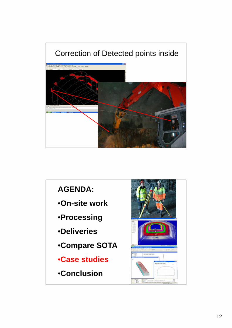
12
Correction of Detected points inside
AGENDA:
•On-site work
P i•Processing
•Deliveries
•Compare SOTA
•Case studies
•Conclusion

13
Concrete thickness analysebefore and after spraying
Concrete thickness analyse

14
Concrete thickness analysebefore and after spraying
Concrete thickness analyse RRT,differential model before after spraying.

15
Planar projection of tunnel
AGENDA:
•On-site work
P i•Processing
•Deliveries
•Compare SOTA
•Case studies
•Conclusion

16
Conclusion• 3D scanning is much faster
• Same accuracy in tunnel data
M lti l f d t• Multiple use of same data
• Thank You for your attention!