far2107bb front e-fusa brochure.pdf · furuno’ s far-21x7-bb series of x- and s-band blackbox...
TRANSCRIPT
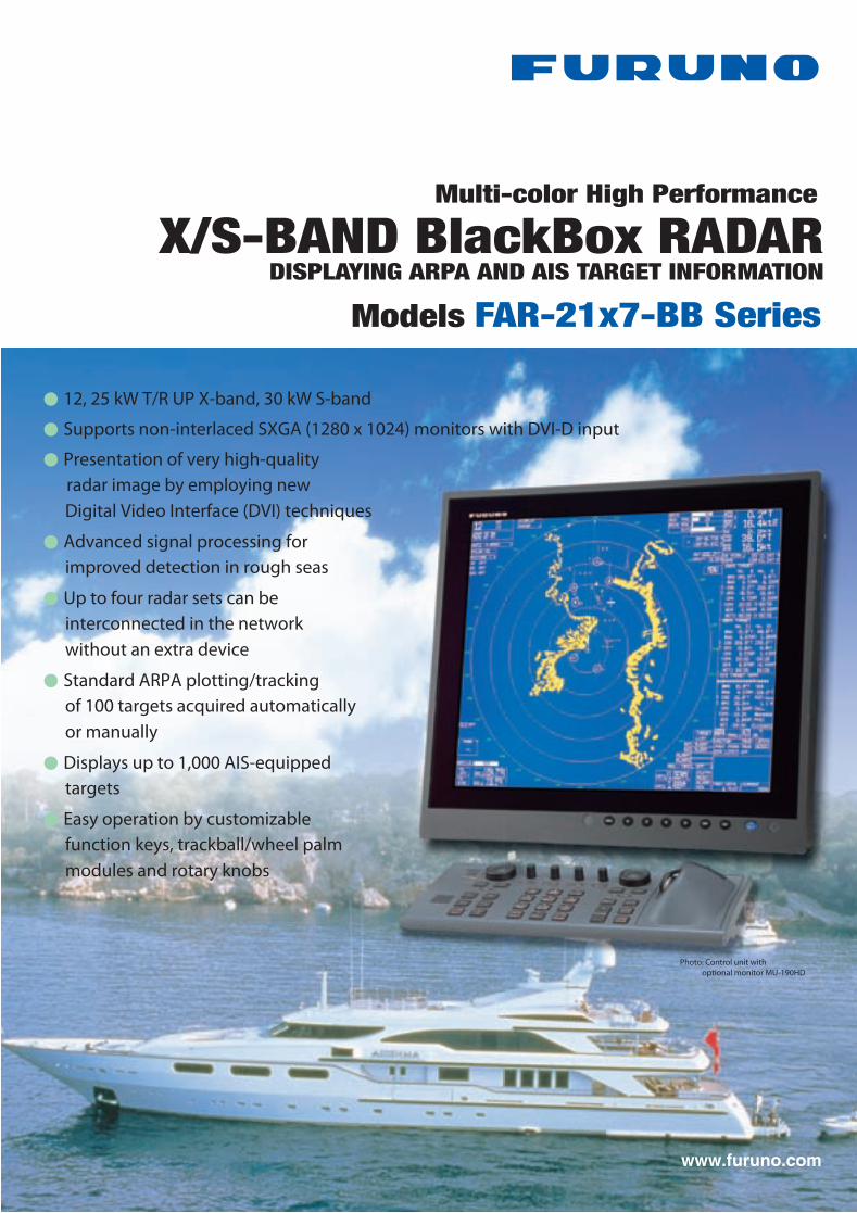
● 12, 25 kW T/R UP X-band, 30 kW S-band
● Supports non-interlaced SXGA (1280 x 1024) monitors with DVI-D input
● Presentation of very high-quality radar image by employing new Digital Video Interface (DVI) techniques
● Advanced signal processing for improved detection in rough seas
● Up to four radar sets can be interconnected in the network without an extra device
● Standard ARPA plotting/tracking of 100 targets acquired automatically or manually
● Displays up to 1,000 AIS-equipped targets
● Easy operation by customizable function keys, trackball/wheel palm modules and rotary knobs
X-Band S-BandRadiator TypeLengthBeamwidth(H)Beamwidth(W)Sidelobe (within 10)Sidelobe (outside 10)
XN-12AF4 ft1.920
-24 dB-30 dB
XN-20AF6.5 ft1.2320
-28 dB-32 dB
XN-24AF8 ft0.9520
-28 dB-32 dB
SN-30AF10 ft2.325
-24 dB-30 dB
S-band 10 ft radiator usable for a HSC
SN-36AF12 ft1.825
-24 dB-30 dB
X-Band
S-Band
RotationGear Box
RotationGear Box
24 rpmRSB-096
42 rpmRSB-097
RSB-098 RSB-099 RSB-10045 rpm
RSB-101 RSB-10221/26 rpm
Output Power
Transceiver
FAR-2117
12 kW
RTR-078
FAR-2127
25 kW
RTR-079
FAR-2137S
30 kW
RTR-080
SPECIFICATIONS OF
Antenna Radiators1. Type Slotted waveguide array2. Beamwidth and sidelobe attenuation
3. Rotation
RF Transceiver1. Frequency X-band: 9410 MHz ± 30 MHz S-band: 3050 MHz ± 30 MHz2. Output power
3. Pulselength/PRR Range scale (nm) Pulselength (µs) PRR (Hz) 0.125, 0.25 0.07 3000 0.5 0.07, 0.15 3000 0.75, 1.5 0.07, 0.15, 0.3 3000, 1500 3 0.15, 0.3, 0.5, 0.7 3000, 1500, 1000 6 0.3, 0.5, 0.7, 1.2 1500, 1000, 600 12, 24 0.5, 0.7, 1.2 1000, 600 48, 96 1.2 6004. I.F. 60 MHz, Logarithmic5. Bandwidth Short pulse: 40 MHz Middle pulse: 10 MHz Long pulse: 3 MHzRadar Display1. Display Unit (Locally arranged) Type: Non-interlaced, Multi-sync monitor (DVI-D) Resolution SXGA (1280 x 1024 pixels)2. Range scales and ring intervals (nm) Range: .125, .25, .5, .75, 1.5, 3, 6, 12, 24, 48, 96 Ring: .025, .05, .1, .25, .25, .5, 1, 2, 4, 8, 163. Minimum range 30 m on 0.75 nm range scale4. Range discrimination 30 m on 0.75 nm range scale5. Range ring accuracy +0.2 %6. Presentation modes Head-Up, Course-Up, North-Up, North-Up TM7. ARPA Acquisition: 100 targets Tracking: Automatic tracking of all acquired targets in 0.1 to 32 nm8. AIS Display (Data input from AIS is required) Targets: 1,000 targets
Power Supply (specify when ordering)1. Processor Unit 24 VDC or 115/230 VAC, 1ø, 50/60 Hz, 7.6 A (FAR-2117-BB: 24 rpm at 24 VDC), 8.8 A (FAR-2127-BB: 24 rpm at 24 VDC) 440 VAC, 1ø, 50/60 Hz with RU-18032. Antenna Unit FAR-2137S-BB: 200 VAC, 3ø, 50 Hz; 220 VAC, 3ø, 60 Hz; 380 VAC, 3ø, 50 Hz; 440 VAC, 3ø, 60 Hz; 110 VAC, 3ø, 60 Hz with RU-5693; 220 VAC, 3ø, 50 Hz with RU-6522; 440 VAC, 3ø, 50 Hz with RU-5466-1
Equipment ListStandard1. Processor Unit RPU-013 1 unit2. Control Unit RCU-014 or Trackball Control Unit RCU-015 1 unit (Specify when ordering)3. Antenna Unit with cable, 15/30/40/50 m 1 pc4. Power Supply unit PSU-007 for FAR-2137S 1 unit5. Standard Spare Parts and Installation MaterialsOption1. Performance Monitor PM-31 for X-band, PM-51 for S-band2. Remote Control Unit RCU-0163. Gyro Interface GC-104. DVI-Analog RGB Conversion Kit OP03-1805. RGB Connector DSUB-BNC-1 (for VDR)6. Chart/Memory Card Interface Unit CU-200-FAR7. Transformer RU-1803/5466-1/5693/65228. Recti�er RU-3424/1746B9. Junction Box RJB-001 (for expanded antenna cable, 100-300 m)10. Antenna Cable RW-960011. Switching Hub HUB-100
RW-9600, 15 m
RW-9600, 15 m
For FAR-2117-BB/2127-BB
Junction Box RJB-001
Junction Box RJB-001
200 VAC, 3 , 50 Hz*220 VAC, 3 , 60 Hz380 VAC, 3 , 50 Hz440 VAC, 3 , 60 Hz
DVI
GPS Compass
AIS FA-100
Switching HUB
IEC 61162-1
Option or Shipyard Supply
RW-960015/30/40/50 m
Performance MonitorPM-51
Performance MonitorPM-31
For FAR-2137S-BB
Antenna Unit
Power Supply UnitPSU-007
250V-DPYCY-1.5
ProcessorUnit
RPU-013
PowerSpecify power supply when ordering*Optional transformer required
Monitor(1280 x1024 pixels)
Control UnitRCU-014
Trackball Control UnitRCU-015
03S-961010/20/30 m
10/20/30 m
10/20/30 m
Remote Control UnitRCU-016
DVI-Analog RGBConvirsion Kit
Gyro InterfaceGC-10
IEC 61162-1
IEC 61162-1
RW-4846
Gyro ConverterAD-100
Ethernet100Base-TX
Chart/Menory Card Interface Unit
CU-200
FAR-21x7/28x7
GPS Navigator
ECDIS FEA-21x7/28x7INS VOYAGER
Gyro Compass
115 VAC, 1 , 50/60 Hz230 VAC, 1 , 50/60 Hz440 VAC, 1 , 50/60 Hz*
24 VDC
70 - 270 m
555
21.
9"18
0.7
"
468 18.4"
124
4.9
"
300 11.8"4- 15
XN-12AF:1260 49.6"
300 11.8"468 18.4"
137
5.4
"
570
22.
4"18
0.7
"
XN-20AF: 2040 80.3"XN-24AF: 2550 100.4"
XN-12AF: 33 kg 73 lbXN-20AF: 39 kg 86 lbXN-24AF: 42 kg 93 lbSN-30AF: 135 kg 298 lbSN-36AF: 142 kg 313 lb
4- 15
1054.1"
1054.1"
8- 15
286 11.3"250 9.8"
432
17.
0"
350
13.
8"
530 20.9"
1104.3"
1104.3"
1003.9"
1375.4"
432
17.
0"
561 22.1"
275 10.8"378 14.9"
420
16.
5"71
0 2
8.0"18
4 7
.2" 421 16.6"
432 17.0"
SN-36AF: 3765 148.2"SN-30AF: 3090 121.7"
92 3.6"398 15.7"308 12.1"
136
5.4
"18
0 7
.1"
4- 4 39 1.5"
183 7.2" 350 13.8"7
0.3"
385 15.2"370 14.6"
25 1.0"
340
13.
4"38
0 1
5.0"
2- 7
410
16.
1"
110 4.3" 4- 4
160 6.3"
136
5.4
"18
0 7
.1"
89 3.5"
35 1.4"
Antenna Unit
Interconnection Diagram
Processor UnitRPU-01310 kg 22 lb
Control Unit RCU-0143.7 kg 8.2 lb
TrackballControl UnitRCU-0152.4 kg 5.3 lb
Photo: Control unit with optional monitor MU-190HD
1011-pdfCatalogue No. R-187c
FURUNO ELECTRIC CO., LTD.Nishinomiya, Hyogo, Japanwww.furuno.co.jp
FURUNO U.S.A., INC.Camas, Washington, U.S.A.www.furunousa.com
FURUNO (UK) LIMITEDHavant, Hampshire, U.K.www.furuno.co.uk
FURUNO FRANCE S.A.S.Bordeaux-Mérignac, Francewww.furuno.fr
FURUNO ESPAÑA S.A.Madrid, Spainwww.furuno.es
FURUNO DANMARK AS Hvidovre, Denmarkwww.furuno.dk
FURUNO NORGE A/SÅlesund, Norwaywww.furuno.no
FURUNO SVERIGE ABVästra Frölunda, Swedenwww.furuno.se
FURUNO FINLAND OYEspoo, Finlandwww.furuno.�
FURUNO POLSKA Sp. Z o.o.Gdynia, Polandwww.furuno.pl
FURUNO EURUS LLCSt. Petersburg, Russian Federationwww.furuno.com.ru
FURUNO DEUTSCHLAND GmbHRellingen, Germanywww.furuno.de
FURUNO HELLAS S.A.Piraeus, Greece
RICO (PTE) LTDSingaporewww.rico.com.sg
SPECIFICATIONS SUBJECT TO CHANGE WITHOUT NOTICEAll brand and product names are registered trademarks, trademarks or service marks of their respective holders
www.furuno.com
FURUNO’ s FAR-21x7-BB series of X- and S-band BlackBox Radars are constructed with our �nest commercial grade components and technology. These precision quality radar systems are designed for high end vessels and offer advanced target detection performance for safe navigation.
The BlackBox Radars work with virtually any size multi-sync SXGA (1280 x 1024) LCD or CRT monitor. Furuno also offers a premier line of high-quality LCD moni tors that are a per fect compl iment to the FAR-21x7-BB Radar series. FURUNO’ s MU-155C is a high-resolution LCD monitor that features a variety of features and inputs, including 2 RGB analog, 1 DVI-D and 3 NTSC/PAL v ideo inpu ts . Connec t ing a high-resolution SXGA monitor provides crisp radar images, which are presented in selectable colors with a
day and night background for easy observation in any lighting condition. Different colors are assigned for marks, symbols and text for user-friendly operation.
Target detection is enhanced by employing sophisticated signal processing techniques such as echo stretch, echo average and anti-clutter functions. With useful functions including ARPA, AIS target display, target trail, chart overlay and radar map, the operator can improve navigation ef�ciency and safety while cruising.
The radar antenna is available with 4, 6.5, or 8 ft radiator. For the X-band, the rotation speed is selectable from 24 rpm for standard radar or 42 rpm for high speed craft (HSC). The S-band radar is available with the antenna radiator of 10 or 12 feet. The S-band radar assures target detection in adverse weather where an X-band is heavily affected by sea or rain clutter.
The �nest BlackBox Radar you can own o�ers unmatched performance and a new user-friendly interfaceThe �nest BlackBox Radar you can own o�ers unmatched performance and a new user-friendly interface
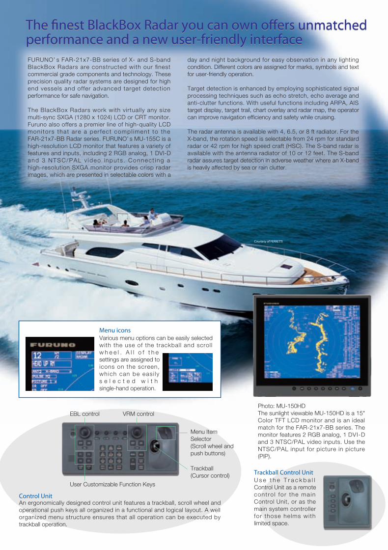
Photo: MU-150HDThe sunlight viewable MU-150HD is a 15" Color TFT LCD monitor and is an ideal match for the FAR-21x7-BB series. The monitor features 2 RGB analog, 1 DVI-D and 3 NTSC/PAL video inputs. Use the NTSC/PAL input for picture in picture (PIP).
Various menu options can be easily selected with the use of the trackball and scroll w h e e l . A l l o f t h e settings are assigned to icons on the screen, which can be eas i ly s e l e c t e d w i t h single-hand operation.
The radar can be connected to an Ethernet network for a variety of user requirements. Each of X- and S-band radars can be interconnected without requiring extra options. Up to four radar sets can be interchanged in the network. In addition, the essential navigational information including the electronic chart, L/L, COG, SOG, STW, etc., can be shared in the network.
A variety of navigational information, own ship status, radar plotting data, wind, water temperature and information from other shipborne sensors are displayed in the cells.
The ta rget t ra i l s feature gene ra tes monotone o r gradual shading afterglow on all objects on the display. This feature is useful to show own ship movement and other ship tracks in a speci�c �shing operation. The trail t ime is ad jus tab le a t 30 s e c o n d s i n t e r v a l s o r continuous.
Up to 200 waypoints and up to 30 routes can be stored. Each route may c o n t a i n u p t o 3 0 waypoints. A radar map is a combination of map lines and marks. The radar map has the capacity of 20,000 points for lines and marks.
This radar incorporates a VideoPlotter that allows the user to display electronic char ts (Nav ion ics and Furuno Charts), plot own and other ship’s track, enable entry of waypoints/ routes, and make a radar m a p . A c h a r t m a y b e over la id wi th the radar i m a g e . O p t i o n a l c a r d reader required.
U s e t h e T r a c k b a l l Control Unit as a remote cont ro l fo r the main Control Unit, or as the main system controller for those helms with limited space.
Control UnitAn ergonomically designed control unit features a trackball, scroll wheel and operational push keys all organized in a functional and logical layout. A well organized menu structure ensures that all operation can be executed by trackball operation.
100 Base-TX Ethernet Network System
Radar System 1 Radar System 2
100 Base-TXOther Radar Images, Chart Information,COG, SOG, STW, etc.
Interswitch
Menu icons
Trackball Control Unit
EBL control VRM control
Courtesy of FERRETTI
Menu ItemSelector(Scroll wheel andpush buttons)
Trackball(Cursor control)
User Customizable Function Keys
X-band antenna
S-band antenna
8 ft antenna(4 or 6.5 ft also available)
10 ft antenna(12 ft also available)
FAR-2117-BB: X-band, 12 kW, TR upFAR-2127-BB: X-band, 25 kW, TR up
FAR-2137S-BB: S-band, 30 kW, TR up
Automatically acquired targets AIS-equipped target
Own Shipdata cell Water temp,
Depth, Wind
Magnify
AIS Information
DATA Cell 1Tracking data
AIS / ARPA
Chart Overlay
Radar Map
Target Trails
DATA Cell 2Tracking data
DATA Cell 3AIS Information

FURUNO’ s FAR-21x7-BB series of X- and S-band BlackBox Radars are constructed with our �nest commercial grade components and technology. These precision quality radar systems are designed for high end vessels and offer advanced target detection performance for safe navigation.
The BlackBox Radars work with virtually any size multi-sync SXGA (1280 x 1024) LCD or CRT monitor. Furuno also offers a premier line of high-quality LCD moni tors that are a per fect compl iment to the FAR-21x7-BB Radar series. FURUNO’ s MU-155C is a high-resolution LCD monitor that features a variety of features and inputs, including 2 RGB analog, 1 DVI-D and 3 NTSC/PAL v ideo inpu ts . Connec t ing a high-resolution SXGA monitor provides crisp radar images, which are presented in selectable colors with a
day and night background for easy observation in any lighting condition. Different colors are assigned for marks, symbols and text for user-friendly operation.
Target detection is enhanced by employing sophisticated signal processing techniques such as echo stretch, echo average and anti-clutter functions. With useful functions including ARPA, AIS target display, target trail, chart overlay and radar map, the operator can improve navigation ef�ciency and safety while cruising.
The radar antenna is available with 4, 6.5, or 8 ft radiator. For the X-band, the rotation speed is selectable from 24 rpm for standard radar or 42 rpm for high speed craft (HSC). The S-band radar is available with the antenna radiator of 10 or 12 feet. The S-band radar assures target detection in adverse weather where an X-band is heavily affected by sea or rain clutter.
The �nest BlackBox Radar you can own o�ers unmatched performance and a new user-friendly interfaceThe �nest BlackBox Radar you can own o�ers unmatched performance and a new user-friendly interface
Photo: MU-150HDThe sunlight viewable MU-150HD is a 15" Color TFT LCD monitor and is an ideal match for the FAR-21x7-BB series. The monitor features 2 RGB analog, 1 DVI-D and 3 NTSC/PAL video inputs. Use the NTSC/PAL input for picture in picture (PIP).
Various menu options can be easily selected with the use of the trackball and scroll w h e e l . A l l o f t h e settings are assigned to icons on the screen, which can be eas i ly s e l e c t e d w i t h single-hand operation.
The radar can be connected to an Ethernet network for a variety of user requirements. Each of X- and S-band radars can be interconnected without requiring extra options. Up to four radar sets can be interchanged in the network. In addition, the essential navigational information including the electronic chart, L/L, COG, SOG, STW, etc., can be shared in the network.
A variety of navigational information, own ship status, radar plotting data, wind, water temperature and information from other shipborne sensors are displayed in the cells.
The ta rget t ra i l s feature gene ra tes monotone o r gradual shading afterglow on all objects on the display. This feature is useful to show own ship movement and other ship tracks in a speci�c �shing operation. The trail t ime is ad jus tab le a t 30 s e c o n d s i n t e r v a l s o r continuous.
Up to 200 waypoints and up to 30 routes can be stored. Each route may c o n t a i n u p t o 3 0 waypoints. A radar map is a combination of map lines and marks. The radar map has the capacity of 20,000 points for lines and marks.
This radar incorporates a VideoPlotter that allows the user to display electronic char ts (Nav ion ics and Furuno Charts), plot own and other ship’s track, enable entry of waypoints/ routes, and make a radar m a p . A c h a r t m a y b e over la id wi th the radar i m a g e . O p t i o n a l c a r d reader required.
U s e t h e T r a c k b a l l Control Unit as a remote cont ro l fo r the main Control Unit, or as the main system controller for those helms with limited space.
Control UnitAn ergonomically designed control unit features a trackball, scroll wheel and operational push keys all organized in a functional and logical layout. A well organized menu structure ensures that all operation can be executed by trackball operation.
100 Base-TX Ethernet Network System
Radar System 1 Radar System 2
100 Base-TXOther Radar Images, Chart Information,COG, SOG, STW, etc.
Interswitch
Menu icons
Trackball Control Unit
EBL control VRM control
Courtesy of FERRETTI
Menu ItemSelector(Scroll wheel andpush buttons)
Trackball(Cursor control)
User Customizable Function Keys
X-band antenna
S-band antenna
8 ft antenna(4 or 6.5 ft also available)
10 ft antenna(12 ft also available)
FAR-2117-BB: X-band, 12 kW, TR upFAR-2127-BB: X-band, 25 kW, TR up
FAR-2137S-BB: S-band, 30 kW, TR up
Automatically acquired targets AIS-equipped target
Own Shipdata cell Water temp,
Depth, Wind
Magnify
AIS Information
DATA Cell 1Tracking data
AIS / ARPA
Chart Overlay
Radar Map
Target Trails
DATA Cell 2Tracking data
DATA Cell 3AIS Information

● 12, 25 kW T/R UP X-band, 30 kW S-band
● Supports non-interlaced SXGA (1280 x 1024) monitors with DVI-D input
● Presentation of very high-quality radar image by employing new Digital Video Interface (DVI) techniques
● Advanced signal processing for improved detection in rough seas
● Up to four radar sets can be interconnected in the network without an extra device
● Standard ARPA plotting/tracking of 100 targets acquired automatically or manually
● Displays up to 1,000 AIS-equipped targets
● Easy operation by customizable function keys, trackball/wheel palm modules and rotary knobs
X-Band S-BandRadiator TypeLengthBeamwidth(H)Beamwidth(W)Sidelobe (within 10)Sidelobe (outside 10)
XN-12AF4 ft1.920
-24 dB-30 dB
XN-20AF6.5 ft1.2320
-28 dB-32 dB
XN-24AF8 ft0.9520
-28 dB-32 dB
SN-30AF10 ft2.325
-24 dB-30 dB
S-band 10 ft radiator usable for a HSC
SN-36AF12 ft1.825
-24 dB-30 dB
X-Band
S-Band
RotationGear Box
RotationGear Box
24 rpmRSB-096
42 rpmRSB-097
RSB-098 RSB-099 RSB-10045 rpm
RSB-101 RSB-10221/26 rpm
Output Power
Transceiver
FAR-2117
12 kW
RTR-078
FAR-2127
25 kW
RTR-079
FAR-2137S
30 kW
RTR-080
SPECIFICATIONS OF
Antenna Radiators1. Type Slotted waveguide array2. Beamwidth and sidelobe attenuation
3. Rotation
RF Transceiver1. Frequency X-band: 9410 MHz ± 30 MHz S-band: 3050 MHz ± 30 MHz2. Output power
3. Pulselength/PRR Range scale (nm) Pulselength (µs) PRR (Hz) 0.125, 0.25 0.07 3000 0.5 0.07, 0.15 3000 0.75, 1.5 0.07, 0.15, 0.3 3000, 1500 3 0.15, 0.3, 0.5, 0.7 3000, 1500, 1000 6 0.3, 0.5, 0.7, 1.2 1500, 1000, 600 12, 24 0.5, 0.7, 1.2 1000, 600 48, 96 1.2 6004. I.F. 60 MHz, Logarithmic5. Bandwidth Short pulse: 40 MHz Middle pulse: 10 MHz Long pulse: 3 MHzRadar Display1. Display Unit (Locally arranged) Type: Non-interlaced, Multi-sync monitor (DVI-D) Resolution SXGA (1280 x 1024 pixels)2. Range scales and ring intervals (nm) Range: .125, .25, .5, .75, 1.5, 3, 6, 12, 24, 48, 96 Ring: .025, .05, .1, .25, .25, .5, 1, 2, 4, 8, 163. Minimum range 30 m on 0.75 nm range scale4. Range discrimination 30 m on 0.75 nm range scale5. Range ring accuracy +0.2 %6. Presentation modes Head-Up, Course-Up, North-Up, North-Up TM7. ARPA Acquisition: 100 targets Tracking: Automatic tracking of all acquired targets in 0.1 to 32 nm8. AIS Display (Data input from AIS is required) Targets: 1,000 targets
Power Supply (specify when ordering)1. Processor Unit 24 VDC or 115/230 VAC, 1ø, 50/60 Hz, 7.6 A (FAR-2117-BB: 24 rpm at 24 VDC), 8.8 A (FAR-2127-BB: 24 rpm at 24 VDC) 440 VAC, 1ø, 50/60 Hz with RU-18032. Antenna Unit FAR-2137S-BB: 200 VAC, 3ø, 50 Hz; 220 VAC, 3ø, 60 Hz; 380 VAC, 3ø, 50 Hz; 440 VAC, 3ø, 60 Hz; 110 VAC, 3ø, 60 Hz with RU-5693; 220 VAC, 3ø, 50 Hz with RU-6522; 440 VAC, 3ø, 50 Hz with RU-5466-1
Equipment ListStandard1. Processor Unit RPU-013 1 unit2. Control Unit RCU-014 or Trackball Control Unit RCU-015 1 unit (Specify when ordering)3. Antenna Unit with cable, 15/30/40/50 m 1 pc4. Power Supply unit PSU-007 for FAR-2137S 1 unit5. Standard Spare Parts and Installation MaterialsOption1. Performance Monitor PM-31 for X-band, PM-51 for S-band2. Remote Control Unit RCU-0163. Gyro Interface GC-104. DVI-Analog RGB Conversion Kit OP03-1805. RGB Connector DSUB-BNC-1 (for VDR)6. Chart/Memory Card Interface Unit CU-200-FAR7. Transformer RU-1803/5466-1/5693/65228. Recti�er RU-3424/1746B9. Junction Box RJB-001 (for expanded antenna cable, 100-300 m)10. Antenna Cable RW-960011. Switching Hub HUB-100
RW-9600, 15 m
RW-9600, 15 m
For FAR-2117-BB/2127-BB
Junction Box RJB-001
Junction Box RJB-001
200 VAC, 3 , 50 Hz*220 VAC, 3 , 60 Hz380 VAC, 3 , 50 Hz440 VAC, 3 , 60 Hz
DVI
GPS Compass
AIS FA-100
Switching HUB
IEC 61162-1
Option or Shipyard Supply
RW-960015/30/40/50 m
Performance MonitorPM-51
Performance MonitorPM-31
For FAR-2137S-BB
Antenna Unit
Power Supply UnitPSU-007
250V-DPYCY-1.5
ProcessorUnit
RPU-013
PowerSpecify power supply when ordering*Optional transformer required
Monitor(1280 x1024 pixels)
Control UnitRCU-014
Trackball Control UnitRCU-015
03S-961010/20/30 m
10/20/30 m
10/20/30 m
Remote Control UnitRCU-016
DVI-Analog RGBConvirsion Kit
Gyro InterfaceGC-10
IEC 61162-1
IEC 61162-1
RW-4846
Gyro ConverterAD-100
Ethernet100Base-TX
Chart/Menory Card Interface Unit
CU-200
FAR-21x7/28x7
GPS Navigator
ECDIS FEA-21x7/28x7INS VOYAGER
Gyro Compass
115 VAC, 1 , 50/60 Hz230 VAC, 1 , 50/60 Hz440 VAC, 1 , 50/60 Hz*
24 VDC
70 - 270 m
555
21.
9"18
0.7
"468 18.4"
124
4.9
"
300 11.8"4- 15
XN-12AF:1260 49.6"
300 11.8"468 18.4"
137
5.4
"
570
22.
4"18
0.7
"
XN-20AF: 2040 80.3"XN-24AF: 2550 100.4"
XN-12AF: 33 kg 73 lbXN-20AF: 39 kg 86 lbXN-24AF: 42 kg 93 lbSN-30AF: 135 kg 298 lbSN-36AF: 142 kg 313 lb
4- 15
1054.1"
1054.1"
8- 15
286 11.3"250 9.8"
432
17.
0"
350
13.
8"
530 20.9"
1104.3"
1104.3"
1003.9"
1375.4"
432
17.
0"
561 22.1"
275 10.8"378 14.9"
420
16.
5"71
0 2
8.0"18
4 7
.2" 421 16.6"
432 17.0"
SN-36AF: 3765 148.2"SN-30AF: 3090 121.7"
92 3.6"398 15.7"308 12.1"
136
5.4
"18
0 7
.1"
4- 4 39 1.5"
183 7.2" 350 13.8"7
0.3"
385 15.2"370 14.6"
25 1.0"
340
13.
4"38
0 1
5.0"
2- 7
410
16.
1"
110 4.3" 4- 4
160 6.3"
136
5.4
"18
0 7
.1"
89 3.5"
35 1.4"
Antenna Unit
Interconnection Diagram
Processor UnitRPU-01310 kg 22 lb
Control Unit RCU-0143.7 kg 8.2 lb
TrackballControl UnitRCU-0152.4 kg 5.3 lb
Photo: Control unit with optional monitor MU-190HD
1011-pdfCatalogue No. R-187c
FURUNO ELECTRIC CO., LTD.Nishinomiya, Hyogo, Japanwww.furuno.co.jp
FURUNO U.S.A., INC.Camas, Washington, U.S.A.www.furunousa.com
FURUNO (UK) LIMITEDHavant, Hampshire, U.K.www.furuno.co.uk
FURUNO FRANCE S.A.S.Bordeaux-Mérignac, Francewww.furuno.fr
FURUNO ESPAÑA S.A.Madrid, Spainwww.furuno.es
FURUNO DANMARK AS Hvidovre, Denmarkwww.furuno.dk
FURUNO NORGE A/SÅlesund, Norwaywww.furuno.no
FURUNO SVERIGE ABVästra Frölunda, Swedenwww.furuno.se
FURUNO FINLAND OYEspoo, Finlandwww.furuno.�
FURUNO POLSKA Sp. Z o.o.Gdynia, Polandwww.furuno.pl
FURUNO EURUS LLCSt. Petersburg, Russian Federationwww.furuno.com.ru
FURUNO DEUTSCHLAND GmbHRellingen, Germanywww.furuno.de
FURUNO HELLAS S.A.Piraeus, Greece
RICO (PTE) LTDSingaporewww.rico.com.sg
SPECIFICATIONS SUBJECT TO CHANGE WITHOUT NOTICEAll brand and product names are registered trademarks, trademarks or service marks of their respective holders
www.furuno.com