fan instruction manual - showadenki.co.jp · fan instruction manual ... wire net in advance. ... it...
TRANSCRIPT

ZF-9501-11E
Fan Instruction Manual
【 Centrifugal V Belt Driven Fan 】
【 Centrifugal Direct-Coupling with Blower Motor Shaft】

Fan Instruction Manual
Introduction We highly appreciate your purchase of this fan made by Showa Denki Co., Ltd.. This instruction manual explains the way of use and maintenance of this Centrifugal V Belt Driven Fan.
Please read this instruction manual in order to make full use of its capacity and operate the machine safely
and without any malfunctions for an extended period of time. Please keep and make full use of this
instruction manual.
This instruction manual explains the way of use of the fan types indicated below.
Main bearing specifications Standard type
Thermo resistive bearing type
Thermo resistive Air‐cooled type
Thermo resistive Water‐cooled type
Pillow type
Those made by Showa Denki Co., Ltd.
Oil Bath type
(System specification system 1) Only the main fan
(System specification system 2) System specifications A (Main fan with base installed and motor
pulley/V belt attached)
(System specification system 3) System specifications AM (Main fan with base, motor pulley, V belt
and electric motor included)
In case that there is a complementary instruction manual regarding special specifications attached, please
take it as a reference.
About the marks that appear in this book
The marks that appear in this book have the following meanings.
Symbolizes that in case of making a wrong use of the system,
there is a chance of dying or getting severely injured.
Symbolizes that in case of making a wrong use of the system,
there is a chance of causing wounds or material damage.
Indicates an action that shouldn't be performed
Indicates a point to be careful with
Indicates an action that must be performed
WARNING
CAUTION

- 1 -
Contents
Page
1. Safety warnings ···································································································· - 2 -
2. Structure and name of the product ··········································································· - 5 -
3. At the time of receipt ····························································································· - 7 -
3. 1. Product check at the time of receipt ····························································· - 7 -
3. 2. Movement and transport ············································································ - 8 -
3. 3. Storage until the installation ······································································ - 8 -
4. Collocation ··········································································································· - 8 -
4. 1 Setting ····································································································· - 8 -
4. 2. Duct connection ························································································ - 9 -
4. 3 Installation of the motor ··········································································· - 10 -
4.4. Operational test ······················································································ - 15 -
5. Operation ··········································································································· - 16 -
5. 1 Operation and maintenance test ································································ - 16 -
5. 2. Lubricant oil replenishment ····································································· - 18 -
5. 3. Belt control ···························································································· - 21 -
5. 4. Warnings regarding the thermo resistive air-cooled type
and water-clloed bearing type ·················· - 21 -
5. 5. Restart after stop or interruption ······························································ - 22 -
6. Guarantee ·········································································································· - 22 -
7. Malfunction causes and measures ·········································································· - 24 -
Inquiry address ·············································································· back side of the cover
- 2 -
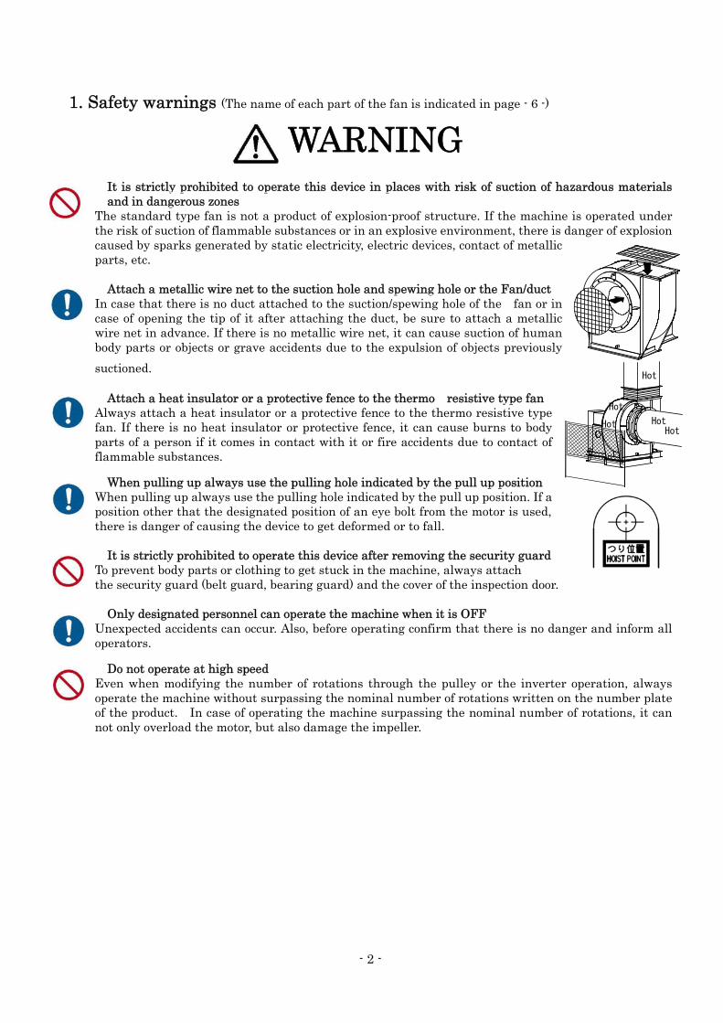
1. Safety warnings (The name of each part of the fan is indicated in page - 6 -)
It is strictly prohibited to operate this device in places with risk of suction of hazardous materials and in dangerous zones
The standard type fan is not a product of explosion-proof structure. If the machine is operated under the risk of suction of flammable substances or in an explosive environment, there is danger of explosion caused by sparks generated by static electricity, electric devices, contact of metallic parts, etc.
Attach a metallic wire net to the suction hole and spewing hole or the Fan/duct
In case that there is no duct attached to the suction/spewing hole of the fan or in case of opening the tip of it after attaching the duct, be sure to attach a metallic wire net in advance. If there is no metallic wire net, it can cause suction of human body parts or objects or grave accidents due to the expulsion of objects previously
suctioned.
Attach a heat insulator or a protective fence to the thermo resistive type fan Always attach a heat insulator or a protective fence to the thermo resistive type fan. If there is no heat insulator or protective fence, it can cause burns to body parts of a person if it comes in contact with it or fire accidents due to contact of flammable substances.
When pulling up always use the pulling hole indicated by the pull up position When pulling up always use the pulling hole indicated by the pull up position. If a position other that the designated position of an eye bolt from the motor is used, there is danger of causing the device to get deformed or to fall.
It is strictly prohibited to operate this device after removing the security guard
To prevent body parts or clothing to get stuck in the machine, always attach the security guard (belt guard, bearing guard) and the cover of the inspection door.
Only designated personnel can operate the machine when it is OFF Unexpected accidents can occur. Also, before operating confirm that there is no danger and inform all operators.
Do not operate at high speed Even when modifying the number of rotations through the pulley or the inverter operation, always operate the machine without surpassing the nominal number of rotations written on the number plate of the product. In case of operating the machine surpassing the nominal number of rotations, it can not only overload the motor, but also damage the impeller.
Hot
Hot
Hot
Hot
Hot
WARNING
- 3 -
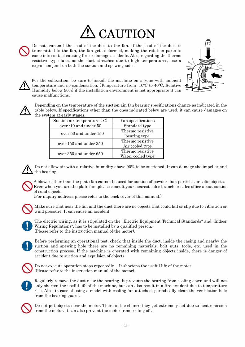
Do not transmit the load of the duct to the fan. If the load of the duct is transmitted to the fan, the fan gets deformed, making the rotation parts to come into contact causing fire or damage accidents. Also, regarding the thermo resistive type fans, as the duct stretches due to high temperatures, use a expansion joint on both the suction and spewing sides.
For the collocation, be sure to install the machine on a zone with ambient
temperature and no condensation. (Temperature from -10ºC to 40ºC, Relative Humidity below 90%) if the installation environment is not appropriate it can cause malfunctions.
Depending on the temperature of the suction air, fan bearing specifications change as indicated in the table below. If specifications other than the ones indicated below are used, it can cause damages on the system at early stages.
Suction air temperature (ºC) Fan specifications over -10 and under 50 Standard type
over 50 and under 150 Thermo resistive bearing type
over 150 and under 350 Thermo resistive Air-cooled type
over 350 and under 650 Thermo resistive Water-cooled type
Do not allow air with a relative humidity above 90% to be suctioned. It can damage the impeller and the bearing. A blower other than the plate fan cannot be used for suction of powder dust particles or solid objects. Even when you use the plate fan, please consult your nearest sales branch or sales office about suction of solid objects. (For inquiry address, please refer to the back cover of this manual.) Make sure that near the fan and the duct there are no objects that could fall or slip due to vibration or wind pressure. It can cause an accident. The electric wiring, as it is stipulated on the "Electric Equipment Technical Standards" and "Indoor Wiring Regulations", has to be installed by a qualified person. (Please refer to the instruction manual of the motor). Before performing an operational test, check that inside the duct, inside the casing and nearby the suction and spewing hole there are no remaining materials, bolt nuts, tools, etc. used in the construction process. If the machine is operated with remaining objects inside, there is danger of accident due to suction and expulsion of objects. Do not execute operation stops repeatedly. It shortens the useful life of the motor. (Please refer to the instruction manual of the motor). Regularly remove the dust near the bearing. It prevents the bearing from cooling down and will not only shorten the useful life of the machine, but can also result in a fire accident due to temperature rise. Also, in case of using a model with cooling fan attached, periodically clean the ventilation hole from the bearing guard. Do not put objects near the motor. There is the chance they get extremely hot due to heat emission from the motor. It can also prevent the motor from cooling off.
1t
CAUTION

- 4 -
Do not get on the belt guard or the bearing guard. It may not only damage the guard, but can also result on a fall accident. Precautions for the use of an inverter to operate the blower. 1) The standard motor may not be used for the operation in some cases as shown below. ・ In the case of no margin for temperature rise in the motor 2) At factory shipment, the setting of a commercial inverter is not suitable for the blower. Change the following values at least. ・Base frequency: Adjust to the rated frequency of the blower (50 Hz or 60 Hz). ・Highest frequency: Adjust to the rated frequency of the blower. ・Maximum output voltage: Adjust to the rated voltage of the motor. ・Upper-limit frequency: Highest frequency: Adjust to the rated frequency of the blower. ・Lower-limit frequency: 25 to 30 Hz (based on the cooling characteristics of the motor). ・V/f characteristics: Change to square reduction torque. ・Acceleration time: 30 to 60 sec. or more If the acceleration time is short, an over-current error
may occur. ・Deceleration time: 30 to 60 sec. or more If the decceleration time is short, a regenerative current
error may occur. 3) Other precautions ・ Vibrations of components (belt, casing, etc.) making up the blower may increase at a specific
frequency. If the increase in vibration cannot be eliminated even after other set values are changed, a resonance point may be causing it. In such a case, set the jump frequency to prevent the increase in frequency.
・If the blower is installed on a vibration isolation table (rubber, spring, etc.), a decrease in frequency may become a resonance frequency. In such a case, set the jump frequency to prevent this symptom (otherwise, the blower and motor are individually affected).
・If the carrier frequency is set higher, current leakage may increase, and the earth leakage breaker may be activated.
・Do not use the inverter output power for applications other than electric motors. For details, see “Use of inverter (frequency converter)” on page 20.
- 5 -
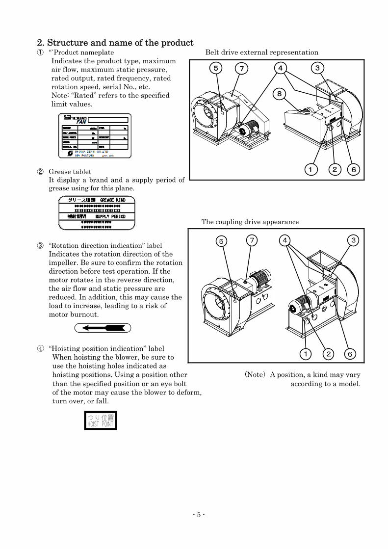
2. Structure and name of the product ① “`Product nameplate Belt drive external representation
Indicates the product type, maximum air flow, maximum static pressure, rated output, rated frequency, rated rotation speed, serial No., etc. Note: “Rated” refers to the specified limit values.
② Grease tablet It display a brand and a supply period of grease using for this plane.
The coupling drive appearance
③ “Rotation direction indication” label Indicates the rotation direction of the impeller. Be sure to confirm the rotation direction before test operation. If the motor rotates in the reverse direction, the air flow and static pressure are reduced. In addition, this may cause the load to increase, leading to a risk of motor burnout.
④ “Hoisting position indication” label When hoisting the blower, be sure to use the hoisting holes indicated as hoisting positions. Using a position other (Note)A position, a kind may vary than the specified position or an eye bolt according to a model. of the motor may cause the blower to deform, turn over, or fall.
3
1 2
45
6
7
8
1 2
345 7
6

- 6 -
⑤“Warning for attaching a metallic wire net” label ⑥"High temperature attention" label If no duct is attached to the intake/discharge When temperature touches it highly, port of the blower or if the tip opens even there might be the burn. (only as for after a duct is attached, be sure to attach the heat-resistant specifications)
a metallic wire net in advance. With no metallic wire net attached, part of human body or objects may be taken in or objects taken in before may rush out, resulting in accidents. (The label is not affixed to the air-cooling type.)
⑦Grease nipple ⑧Belt inspection door *It is not arrange it to the blower of outdoor specifications.
Exploded view schematic Standard structure and name of the components of a Centrifugal V Belt Driven Fan.
The <Specification model 1> is composed from the components ① to ⑩, the <Specification model 2> is composed from the components ① to ⑭ and the <Specification model 3> is composed from the components ① to ⑯.
⑩Bearing guard ⑤Bearing
⑤Bearing
④Shaft ⑬Belt
⑦Companion discharge flange
⑨Cooling fan
⑭Belt guard
②Casing
①Impeller ⑧Shaft seal
⑫Motor pulley
⑮Motor
⑯Slide base
③Suction opening
⑦Companion suction flange
⑪Base
⑥Fan pulley

- 7 -
Exploded view schematic Standard structure and name of the components of a Centrifugal Direct-Coupling with Blower Motor
Shaft.
*The shaft seal (⑧) is not included in some machine models (sirocco fan). *The cooling fan (⑨) is installed on the thermo resistive air-cooled type and thermo resistive
water-cooled type. (Note)The form of the impeller (①) differs depending on the machine model as indicated below.
Sirocco fan Turbo fan Airfoil fan Plate fan Turbo blower
There are the below indicated types of bearing(⑧).
Pillow type S type, G type BW type (water cooled type) OB type (oil bath type)
(Commercial product) (Showa Denki product) (Showa Denki product) (Showa Denki product)
3. At the time of receipt 3. 1. Product check at the time of receipt
Although we only ship products that have passed an intensive exam, we ask you to check the following points at the time of receipt. *Does the fan match the model you ordered?*Is there any abnormality (damage or deformation) caused during the delivery? *Are all the accessories included? *Is there any loosening on the bolts or nuts?
⑦Companion suction flange
③Suction opening
①Impeller
②Casing
⑦Companion discharge flange
⑩Bearing guard
⑰Coupling guard
⑧Shaft seal
⑨Cooling fan
④Shaft
⑯Coupling
⑧Bearing
⑮Motor
- 8 -
More than 40mm
3. 2. Movement and transport When pulling up for movement or transport, always use the pulling hole indicated by the pull up position. Do not pull up using the suction/spewing flange hole, shaft or eye bolts of the motor. As some models have 3 or more pull up points, in those cases try to use 3 or 4 points when pulling. In case you can only use 2 points for pulling, choose the pulling position considering the load and the balance. Also, as only using 1 point for pulling can be dangerous, please avoid doing so. The pulling up labor must be executed by a qualified person.
3. 3. Storage until the installation In case the machine has to be stored until installation, even when using an indoor storage space, cover the machine completely with a waterproof sheet. (Same for outdoors) If the storage continues for a long period of time (more than 1 month), remove the V belts. Also, to prevent rust from getting to the bearing, remove the bearing guard once a month and manually idle the shaft (Exploded view schematic ④) rotating it about 10 times. Before operating, pull the plug and check there are no water accumulations inside the casing.
4. Collocation 4. 1 Setting
Use a plain and robust structure as the setting foundations for the fan. A setting using unstable foundations cannot only be the cause of abnormal vibrations and malfunctions on the fan, but there is danger of causing abnormal noises and accidents.
4. 1. 1 Selection of the setting place ◆Choose a place with good ventilation and almost no dust or humidity. In case of setting the
machine inside an enclosed room, install a ventilating fan. ◆Secure the necessary space for inspecting the fan. (Pulley side and suction side: more than 1 m,
motor side: more than 0.5 m) ◆Standard type fans cannot be used in an environment where erosive gases, flammable gases or
steam are generated. An exclusive type of fan is necessary. ◆In case of using it outdoors, select a fan with outdoors specifications and build a roof or a fence as
a preventive measure against rain and snow. ◆Use it with the suction and spewing hole opened, and in case that it they are near a wall, separate
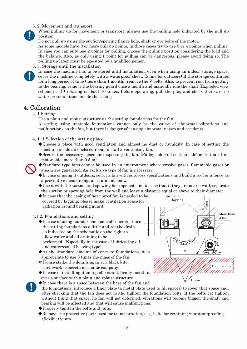
the suction or spewing hole from the wall and leave a distance equal or above to their diameter. ◆In case that the casing of heat-proof fan is needed to be covered by lagging, please make ventilation space for radiation around bearing guard.
4.1.2. Foundations and setting
◆In case of using foundations made of concrete, raise the setting foundations a little and set the drain as indicated on the schematic on the right to allow water and oil draining to be performed. (Especially in the case of lubricating oil and water-cooled bearing type) ◆As the standard amount of concrete foundations, it is
appropriate to use 3 times the mass of the fan. *Please strike the details against a black kite,
earthwork, concrete mechanic company. ◆In case of installing it on top of a stand, firmly install it
over a surface with a plain and robust structure. ◆In case there is a space between the base of the fan and
the foundations, introduce a liner plate (a metal plate used to fill spaces) to cover that space and, after checking that the fan does not rattle, tighten the foundation bolts. If the bolts get tighten without filing that space, he fan will get deformed, vibrations will become bigger, the shaft and bearing will be affected and that will cause malfunctions.
◆Properly tighten the bolts and nuts. ◆Remove the protective parts used for transportation, e.g., bolts for retaining vibration-proofing
(flexible) joints.
Drain
Foundations
Insulation lagging
Mor
e th
an
40m
m
- 9 -
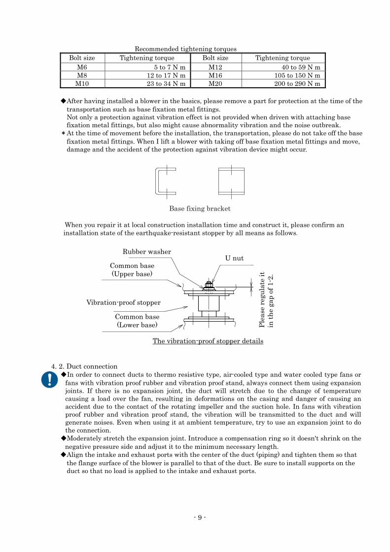
Recommended tightening torques
Bolt size Tightening torque Bolt size Tightening torque M6 5 to 7 N m M12 40 to 59 N m M8 12 to 17 N m M16 105 to 150 N m M10 23 to 34 N m M20 200 to 290 N m
◆After having installed a blower in the basics, please remove a part for protection at the time of the
transportation such as base fixation metal fittings. Not only a protection against vibration effect is not provided when driven with attaching base fixation metal fittings, but also might cause abnormality vibration and the noise outbreak.
*At the time of movement before the installation, the transportation, please do not take off the base fixation metal fittings. When I lift a blower with taking off base fixation metal fittings and move, damage and the accident of the protection against vibration device might occur.
Base fixing bracket
When you repair it at local construction installation time and construct it, please confirm an installation state of the earthquake-resistant stopper by all means as follows.
4. 2. Duct connection
◆In order to connect ducts to thermo resistive type, air-cooled type and water cooled type fans or fans with vibration proof rubber and vibration proof stand, always connect them using expansion joints. If there is no expansion joint, the duct will stretch due to the change of temperature causing a load over the fan, resulting in deformations on the casing and danger of causing an accident due to the contact of the rotating impeller and the suction hole. In fans with vibration proof rubber and vibration proof stand, the vibration will be transmitted to the duct and will generate noises. Even when using it at ambient temperature, try to use an expansion joint to do the connection.
◆Moderately stretch the expansion joint. Introduce a compensation ring so it doesn't shrink on the negative pressure side and adjust it to the minimum necessary length.
◆Align the intake and exhaust ports with the center of the duct (piping) and tighten them so that the flange surface of the blower is parallel to that of the duct. Be sure to install supports on the duct so that no load is applied to the intake and exhaust ports.
Rubber washerU nut
Common base (Upper base)
Vibration-proof stopper
Common base (Lower base)
The vibration-proof stopper details
Ple
ase
regu
late
it
in t
he
gap
of 1
-2.
- 10 -
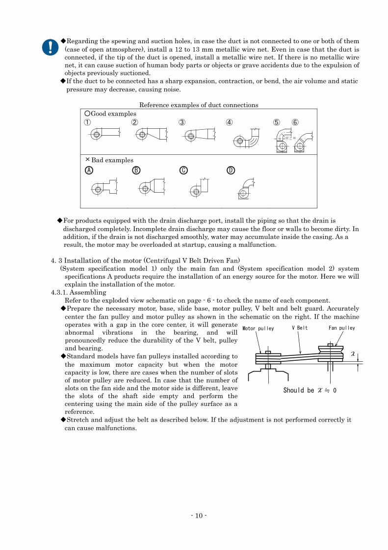
◆Regarding the spewing and suction holes, in case the duct is not connected to one or both of them (case of open atmosphere), install a 12 to 13 mm metallic wire net. Even in case that the duct is connected, if the tip of the duct is opened, install a metallic wire net. If there is no metallic wire net, it can cause suction of human body parts or objects or grave accidents due to the expulsion of objects previously suctioned.
◆If the duct to be connected has a sharp expansion, contraction, or bend, the air volume and static pressure may decrease, causing noise.
Reference examples of duct connections ○Good examples ① ② ③ ④ ⑤ ⑥
×Bad examples
○A ○B ○C ○D
◆For products equipped with the drain discharge port, install the piping so that the drain is
discharged completely. Incomplete drain discharge may cause the floor or walls to become dirty. In addition, if the drain is not discharged smoothly, water may accumulate inside the casing. As a result, the motor may be overloaded at startup, causing a malfunction.
4. 3 Installation of the motor (Centrifugal V Belt Driven Fan)
(System specification model 1) only the main fan and (System specification model 2) system specifications A products require the installation of an energy source for the motor. Here we will explain the installation of the motor.
4.3.1. Assembling Refer to the exploded view schematic on page - 6 - to check the name of each component.
◆Prepare the necessary motor, base, slide base, motor pulley, V belt and belt guard. Accurately center the fan pulley and motor pulley as shown in the schematic on the right. If the machine operates with a gap in the core center, it will generate abnormal vibrations in the bearing, and will pronouncedly reduce the durability of the V belt, pulley and bearing.
◆Standard models have fan pulleys installed according to the maximum motor capacity but when the motor capacity is low, there are cases when the number of slots of motor pulley are reduced. In case that the number of slots on the fan side and the motor side is different, leave the slots of the shaft side empty and perform the centering using the main side of the pulley surface as a reference.
◆Stretch and adjust the belt as described below. If the adjustment is not performed correctly it can cause malfunctions.
X
Should be X ≒ 0
Motor pulley V Belt Fan pulley

- 11 -
How to stretch belt Procedure 1 Span calculation
First calculate the span (ℓ) of the V belt. The span of the V belt is part of the connection of the V belt with the motor pulley and the fan pulley.
Procedure 2 Deflection calculation
When a deflection load is charged, calculate that deflection (δ) following the formula on the right.
Procedure 3 Deflection load measurement Charge the deflection load (P) on the center of the belt span. Read the value of the deflection load when the reflection δ mm has reached the value calculated on Procedure 2. A convenient way to measure the deflection load is to use a tension meter.
Procedure 4 Stretch adjustment
Adjust the stretching of the belt so the previously read deflection load reaches the deflection load indicated in the following table.
Deflection load table
Min. value When stretching a new When re-stretching a belt
M type 38~50 4.9 6.9 6.9
A type
65~8081~9091~105106~
7.88.810.811.8
11.813.716.717.6
9.811.813.715.7
B type115~135136~160
161~
13.717.618.6
20.626.528.4
17.622.524.5
3V type
67~9091~115116~150151~300
17.619.622.525.5
24.528.433.338.2
21.625.529.433.3
5V type180~230231~310311~400
57.869.682.3
85.3103.9121.5
74.590.2105.8
Types of beltspulley diameter
range (mm)Deflection load P(N/unit)
(Note) Small pulley diameters of 3V types and 5V types are shown as nominal diameters. ◆The lack or excess of stretching can cause abnormal phenomenons, which can be distinguished
checking the table below.
(D-d)2
= C2 -
4
ℓ:span (mm)
C:distance from shaft (mm)
D:big pulley diameter (mm)
d:small pulley diameter (mm)
ℓSpan
δ = 0.016 × ℓ
δ : Deflection (mm) ℓ : Span (mm)
Deflection
ℓ
δ D
d
P
C
- 12 -
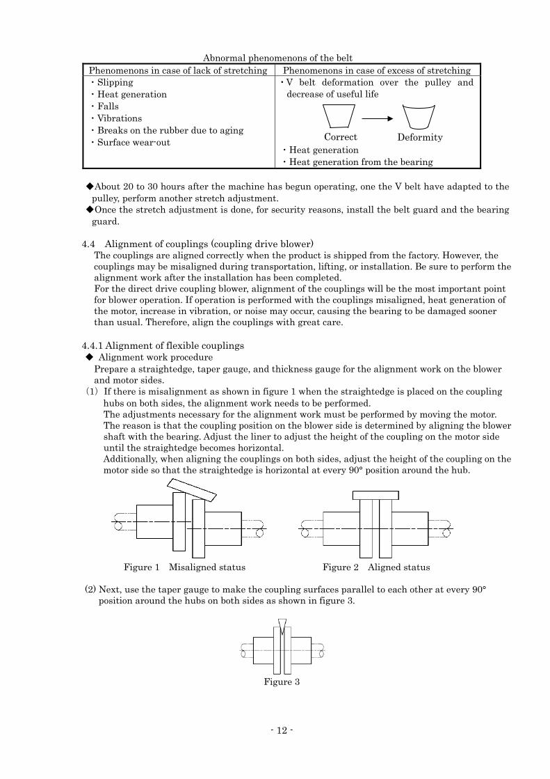
Abnormal phenomenons of the belt Phenomenons in case of lack of stretching Phenomenons in case of excess of stretching ・Slipping ・Heat generation ・Falls ・Vibrations ・Breaks on the rubber due to aging ・Surface wear-out
・ V belt deformation over the pulley and decrease of useful life
・Heat generation ・Heat generation from the bearing
◆About 20 to 30 hours after the machine has begun operating, one the V belt have adapted to the
pulley, perform another stretch adjustment. ◆Once the stretch adjustment is done, for security reasons, install the belt guard and the bearing
guard.
4.4 Alignment of couplings (coupling drive blower) The couplings are aligned correctly when the product is shipped from the factory. However, the couplings may be misaligned during transportation, lifting, or installation. Be sure to perform the alignment work after the installation has been completed. For the direct drive coupling blower, alignment of the couplings will be the most important point for blower operation. If operation is performed with the couplings misaligned, heat generation of the motor, increase in vibration, or noise may occur, causing the bearing to be damaged sooner than usual. Therefore, align the couplings with great care.
4.4.1 Alignment of flexible couplings ◆ Alignment work procedure
Prepare a straightedge, taper gauge, and thickness gauge for the alignment work on the blower and motor sides.
(1)If there is misalignment as shown in figure 1 when the straightedge is placed on the coupling hubs on both sides, the alignment work needs to be performed. The adjustments necessary for the alignment work must be performed by moving the motor. The reason is that the coupling position on the blower side is determined by aligning the blower shaft with the bearing. Adjust the liner to adjust the height of the coupling on the motor side until the straightedge becomes horizontal. Additionally, when aligning the couplings on both sides, adjust the height of the coupling on the motor side so that the straightedge is horizontal at every 90° position around the hub.
Figure 1 Misaligned status Figure 2 Aligned status
(2) Next, use the taper gauge to make the coupling surfaces parallel to each other at every 90° position around the hubs on both sides as shown in figure 3.
Figure 3
Correct Deformity

- 13 -
(3) Alignment tolerances and cautions
C1 Run-out of outer periphery 5/100 mm or less C3-C2 Error of distance between surfaces 5/100 mm or less
The tolerances must be within the values shown in the table on the left.
Figure 4 Coupling alignment tolerances
(CAUTION) For flexible flanged shaft coupling
After the coupling ring on the blower side has been aligned with that on the motor side, couple both couplings directly. At this time, the fitting between the coupling rubber bushing and coupling bolt hole may become difficult. In this case, be aware that the alignment may deviate if excess force is applied.
4.4.1 Alignment of roller chain couplings (Please put grease in this coupling by all means.) (1) It take off a coupling case, a chain. Because grease of the inside falls then, please spread
wastes below. I exclude the cotter pin of the coupling pin and can take off the chain if I let it out of a chain.
(2) It measure in a dial gauge to show a coupling prejudiced mind (heart gap) of the blower side and the drive machine side in figure 2. I wind a chain then and I put a coupling pin and I turn it and do the coupling of both sides and measure it. If heart gaps exceed a permission level to show in table 1 (existence necessary for the kindred spirit for the axis of the coupling, the measurement of the direct angle being examined.), adjustment is necessary. It is necessary to do all the adjustment necessary for this work by the movement of the drive machine. When it is centered, as for the reason, an axis and the bearing of the blower depend on the position of the blower side coupling being decided. Liner (SIMM of the brass), please coordinate the drive machine side until prejudiced minds become less than a permission price. In addition, the prejudiced mind measures it at a position every hub circumference 90 degrees.
(3) Then, I take off a chain and measure an argument. I test whether a coupling side of both sides is parallel. I measure dimensions C between the sprocket of figure 3 by inside micrometers at a position every hub circumference 90 degrees, and the permission levels that the difference of the dimensions shows to table 1 must be less than it. Adjustment is necessary if I exceed it. The C dimensions, please confirm that there is the play that a chain only moves in right and left without unreasonableness in reference to table 2.
Dial gauge
C
Sprocket
Figure 1.The eccentric measurement Figure 2.The measurement of the argument
- 14 -
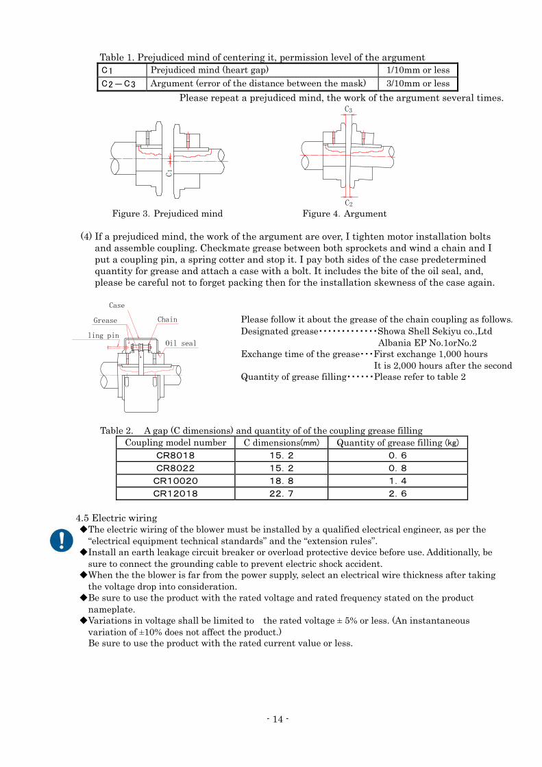
Table 1. Prejudiced mind of centering it, permission level of the argument C1 Prejudiced mind (heart gap) 1/10mm or lessC2-C3 Argument (error of the distance between the mask) 3/10mm or less
Please repeat a prejudiced mind, the work of the argument several times.
C1
C2
C3
Figure 3.Prejudiced mind Figure 4.Argument
(4) If a prejudiced mind, the work of the argument are over, I tighten motor installation bolts and assemble coupling. Checkmate grease between both sprockets and wind a chain and I put a coupling pin, a spring cotter and stop it. I pay both sides of the case predetermined quantity for grease and attach a case with a bolt. It includes the bite of the oil seal, and, please be careful not to forget packing then for the installation skewness of the case again.
Grease
Case
Chain
ling pin Oil seal
Table 2. A gap (C dimensions) and quantity of of the coupling grease filling Coupling model number C dimensions(mm) Quantity of grease filling (kg)
CR8018 15.2 0.6
CR8022 15.2 0.8
CR10020 18.8 1.4
CR12018 22.7 2.6
4.5 Electric wiring ◆The electric wiring of the blower must be installed by a qualified electrical engineer, as per the
“electrical equipment technical standards” and the “extension rules”. ◆Install an earth leakage circuit breaker or overload protective device before use. Additionally, be
sure to connect the grounding cable to prevent electric shock accident. ◆When the the blower is far from the power supply, select an electrical wire thickness after taking
the voltage drop into consideration. ◆Be sure to use the product with the rated voltage and rated frequency stated on the product
nameplate. ◆Variations in voltage shall be limited to the rated voltage ± 5% or less. (An instantaneous
variation of ±10% does not affect the product.) Be sure to use the product with the rated current value or less.
Please follow it about the grease of the chain coupling as follows.
Designated grease・・・・・・・・・・・・・Showa Shell Sekiyu co.,Ltd
Albania EP No.1orNo.2 Exchange time of the grease・・・First exchange 1,000 hours
It is 2,000 hours after the second Quantity of grease filling・・・・・・Please refer to table 2
- 15 -
◆Be sure to install electrical wiring so that the blower rotates in the direction indicated by the arrow mark. If the blower rotates in reverse, its performance will be degraded significantly. The blower is also likely to be overloaded, causing burnout of the motor. Since different motor rotation directions and motor installation directions are available for the blower, the wiring method may differ from the indication on the motor terminal box. Also, since the colors of cables and phases of the power supply may differ depending on the power company, reverse rotation may occur even if cables of the same color are connected. When the power is initially supplied, make sure to confirm the rotation direction.
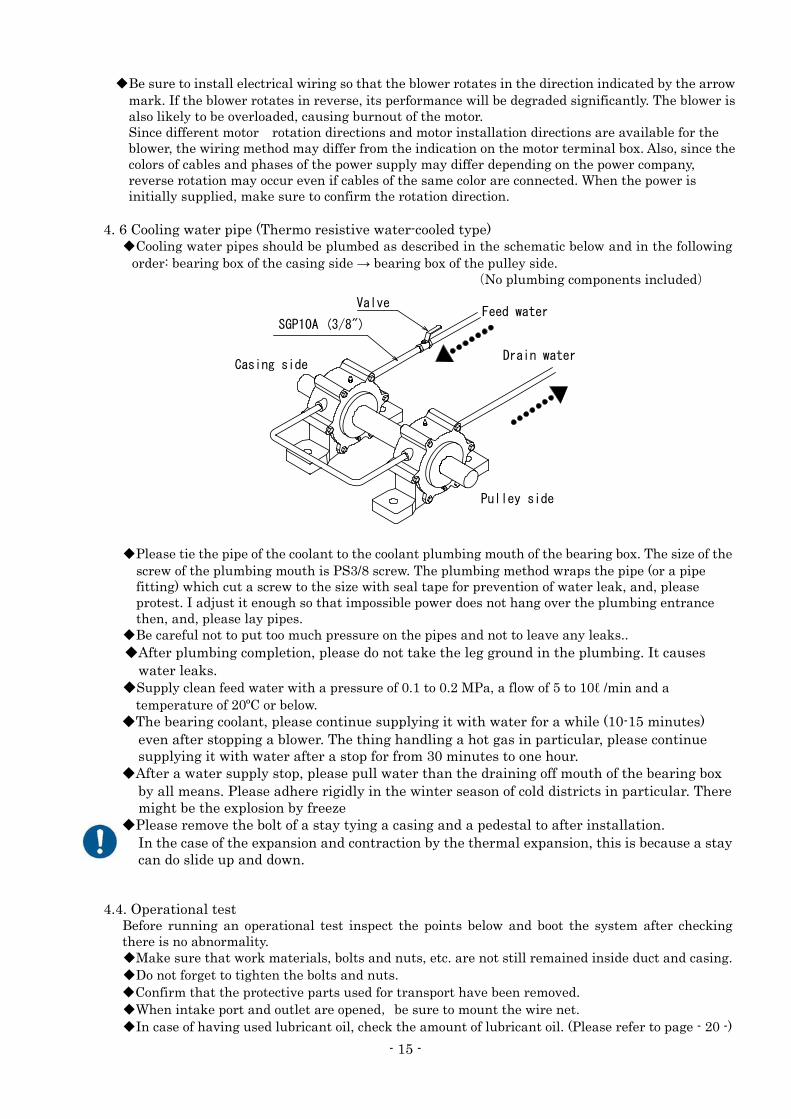
4. 6 Cooling water pipe (Thermo resistive water-cooled type)
◆Cooling water pipes should be plumbed as described in the schematic below and in the following order: bearing box of the casing side → bearing box of the pulley side.
(No plumbing components included)
◆Please tie the pipe of the coolant to the coolant plumbing mouth of the bearing box. The size of the screw of the plumbing mouth is PS3/8 screw. The plumbing method wraps the pipe (or a pipe fitting) which cut a screw to the size with seal tape for prevention of water leak, and, please protest. I adjust it enough so that impossible power does not hang over the plumbing entrance then, and, please lay pipes.
◆Be careful not to put too much pressure on the pipes and not to leave any leaks.. ◆After plumbing completion, please do not take the leg ground in the plumbing. It causes
water leaks. ◆Supply clean feed water with a pressure of 0.1 to 0.2 MPa, a flow of 5 to 10ℓ /min and a
temperature of 20ºC or below. ◆The bearing coolant, please continue supplying it with water for a while (10-15 minutes)
even after stopping a blower. The thing handling a hot gas in particular, please continue supplying it with water after a stop for from 30 minutes to one hour.
◆After a water supply stop, please pull water than the draining off mouth of the bearing box by all means. Please adhere rigidly in the winter season of cold districts in particular. There might be the explosion by freeze
◆Please remove the bolt of a stay tying a casing and a pedestal to after installation. In the case of the expansion and contraction by the thermal expansion, this is because a stay
can do slide up and down.
4.4. Operational test
Before running an operational test inspect the points below and boot the system after checking there is no abnormality. ◆Make sure that work materials, bolts and nuts, etc. are not still remained inside duct and casing. ◆Do not forget to tighten the bolts and nuts. ◆Confirm that the protective parts used for transport have been removed. ◆When intake port and outlet are opened,be sure to mount the wire net. ◆In case of having used lubricant oil, check the amount of lubricant oil. (Please refer to page - 20 -)
Feed water
Casing side
Pulley side
Valve
SGP10A (3/8")
Drain water
- 16 -
[The oil is not replenished at the time of delivery. Be sure to replenish the stipulated amount with the included oil].
◆In case of using a water-cooled type bearing, check the water flow of the cooling water. ◆Check the electric wiring, turn the boot switch OFF and immediately turn in OFF again to check
the rotating direction and check there are no contact noises. ◆In case that the rotation direction is wrong, after turning off the power source, replace 2 of the 3
power source cables with each other and reboot to check the direction of the rotation. ◆If there is no abnormality after checking the above points, let the system rotate continuously and
check the sound of the inside of the casing and the bearing and the vibration of each component is not abnormal, as well as the voltage value.
◆Regarding those models with wind regulator dumper attached, completely close the dumper before starting and after booting the system slowly open it to the designated position. When you do this, also check the voltage value so the motor doesn't overload.
◆For grease lubrication type bearings, replenish the bearings with the specified grease supplied with the blower before starting the formal operation. For grease types and replenishment methods, see pages 13 and 14. (See section 5.2.)
◆In case of using a grease replenishment type bearing, before formally operating it, replenish the grease included with the system. Regarding the type and replenishment of grease, please refer to page - 19 - and - 20 -.
5. Operation 5.1 Operation, maintenance, and inspection Periodic maintenance and inspection are required to operate the blower safely. If the daily inspection is performed on the following items and the results are recorded, abnormalities can be detected early to prevent problems.
1)Check for vibration or abnormal sound once every three months and inspect the insulation once a year. Inspect the motor while referring to its instruction manual.
2)It is recommended to replace the shaft seal or packing at the same time as the bearing is replaced even though the replacement cycle may vary depending on the deterioration status or operating environment.
3)When the blower used is an air-cooling type or quasi-moisture-proofing type blower, or when air containing dust is taken in, gas contact parts (e.g., inside of the casing, impeller, etc.) can be badly corroded and the rotation contact portion can be significantly worn. Therefore, the inspection cycles should be shortened.
- 17 -
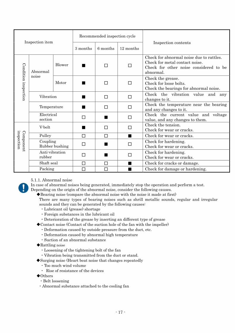
Inspection item
Recommended inspection cycle
Inspection contents 3 months 6 months 12 months
Con
dition in
spection
Abnormal noise
Blower
■
□
□
Check for abnormal noise due to rattles.Check for metal contact noise. Check for other noise considered to be abnormal.
Motor
■ □ □
Check the grease. Check for loose bolts. Check the bearings for abnormal noise.
Vibration
■ □ □
Check the vibration value and any changes to it.
Temperature
■ □ □
Check the temperature near the bearing and any changes to it.
Electrical section
□ ■ □
Check the current value and voltage value, and any changes to them.
Com
ponen
t in
spection
V-belt
■ □ □
Check the tension. Check for wear or cracks.
Pulley □ □ ■ Check for wear or cracks. Coupling Rubber bushing
□ ■ □
Check for hardening. Check for wear or cracks.
Anti-vibration rubber
□ ■ □
Check for hardening. Check for wear or cracks.
Shaft seal □ □ ■ Check for cracks or damage.Packing □ □ ■ Check for damage or hardening.
5.1.1. Abnormal noise In case of abnormal noises being generated, immediately stop the operation and perform a test. Depending on the origin of the abnormal noise, consider the following causes.
◆Bearing noise (compare the abnormal noise with the noise it made at first) There are many types of bearing noises such as shrill metallic sounds, regular and irregular sounds and they can be generated by the following causes: ・Lubricant oil (grease) shortage ・Foreign substances in the lubricant oil ・Deterioration of the grease by inserting an different type of grease
◆Contact noise (Contact of the suction hole of the fan with the impeller) ・Deformation caused by outside pressure from the duct, etc. ・Deformation caused by abnormal high temperature ・Suction of an abnormal substance
◆Rattling noise ・Loosening of the tightening bolt of the fan ・Vibration being transmitted from the duct or stand.
◆Surging noise (Heart beat noise that changes repeatedly ・Too much wind volume ・ Rise of resistance of the devices
◆Others ・Belt loosening ・Abnormal substance attached to the cooling fan
- 18 -
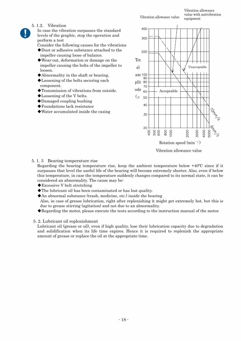
Acceptable
Unacceptable
Vibration allowance value
Vibration allowance value with antivibration equipment
Tot
al
am
plit
ude
(μ
Rotation speed (min-1 )
Vibration allowance value
5. 1.2. Vibration In case the vibration surpasses the standard levels of the graphic, stop the operation and perform a test Consider the following causes for the vibrations ◆Dust or adhesive substance attached to the
impeller causing loose of balance. ◆Wear-out, deformation or damage on the
impeller causing the bolts of the impeller to loosen.
◆Abnormality in the shaft or bearing. ◆Loosening of the bolts securing each
component. ◆Transmission of vibrations from outside. ◆Loosening of the V belts. ◆Damaged coupling bushing ◆Foundations lack resistance ◆Water accumulated inside the casing
5. 1. 3 Bearing temperature rise
Regarding the bearing temperature rise, keep the ambient temperature below +40ºC since if it surpasses that level the useful life of the bearing will become extremely shorter. Also, even if below this temperature, in case the temperature suddenly changes compared to its normal state, it can be considered an abnormality. The cause may be: ◆Excessive V belt stretching ◆The lubricant oil has been contaminated or has lost quality. ◆An abnormal substance (trash, medicine, etc.) inside the bearing
Also, in case of grease lubrication, right after replenishing it might get extremely hot, but this is due to grease stirring (agitation) and not due to an abnormality.
◆Regarding the motor, please execute the tests according to the instruction manual of the motor. 5. 2. Lubricant oil replenishment
Lubricant oil (grease or oil), even if high quality, lose their lubrication capacity due to degradation and solidification when its life time expires. Hence it is required to replenish the appropriate amount of grease or replace the oil at the appropriate time.
- 19 -
5. 2.1. Grease lubrication ◆The grease to replenish is as indicated in the following table
Designated grease brands table
Specifications Manufacturer Component name (brand) Bearing format
Standard type Showa Shell Sekiyu Albania S2 Made by Showa Denki
(S, G types) Albania S3 Pillow type
Thermo resistive type JX Nippon Oil & Energy ENS grease Made by Showa Denki
(S, G , BW types) Toray Dow Corning SH44M Pillow type
(Note) Products have a label that indicates "grease type and replenishment period". ◆If there is a foreign substance in the replenishment oil, it can cause damages on the bearing.
Conserve the grease inside a sealed recipient. Also, do not mix different types of grease. ◆Supply grease and the grease gun, please use the grease set of accessories. ◆Avoid replenishing a big amount of grease at one time to reduce the frequency of replenishment. ◆Perform the grease replenishment while operating after doing a security check. ◆Refer to the next page table to check the standards of grease replenishment period and
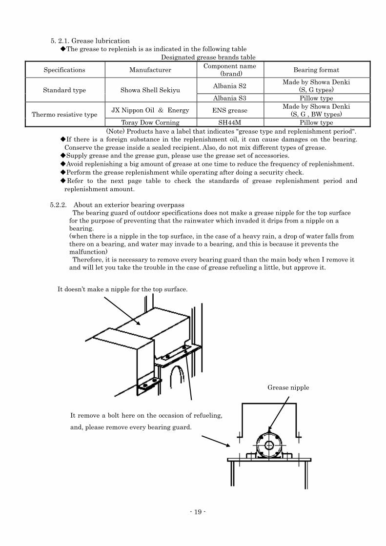
replenishment amount. 5.2.2. About an exterior bearing overpass The bearing guard of outdoor specifications does not make a grease nipple for the top surface
for the purpose of preventing that the rainwater which invaded it drips from a nipple on a bearing. (when there is a nipple in the top surface, in the case of a heavy rain, a drop of water falls from there on a bearing, and water may invade to a bearing, and this is because it prevents the malfunction) Therefore, it is necessary to remove every bearing guard than the main body when I remove it
and will let you take the trouble in the case of grease refueling a little, but approve it.
It doesn’t make a nipple for the top surface.
It remove a bolt here on the occasion of refueling,
and, please remove every bearing guard.
Grease nipple
- 20 -
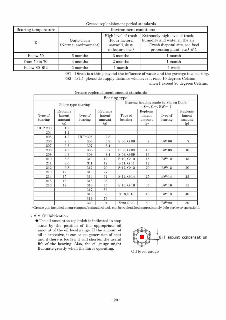
Grease replenishment period standards
Bearing temperature Environment conditions
℃ Quite clean
(Normal environment)
High level of trash (Flour factory, sawmill, dust
collectors, etc.)
Extremely high level of trash, humidity and water in the air
(Trash disposal site, sea food processing plant, etc.) ※1
Below 50 6 months 3 months 1 month
from 50 to 70 3 months 2 months 1 month
Below 80 ※2 2 months 1 month 1 week
※1 Direct is a thing beyond the influence of water and the garbage to a bearing. ※2 1/1.5, please do supply distance whenever it rises 10 degrees Celsius
when I exceed 80 degrees Celsius. Grease replenishment amount standards
Bearing type
Pillow type bearing Bearing housing made by Showa Denki
( S-, G-, BW- )
Type of bearing
Replenishment
amount (g)
Type of bearing
Replenishment
amount (g)
Type of bearing
Replenishment
amount (g)
Type of bearing
Replenishment
amount (g)
UCP-203 1.2 204 1.2 205 1.3 UCP-305 2.8 206 2.3 306 3.9 S-06, G-06 7 BW-06 7 207 3.5 307 5.4 208 4.3 308 6.7 S-08, G-08 10 BW-08 10 209 4.9 309 8.4 S-09, G-09 13 210 5.6 310 12 S-10, G-10 15 BW-10 15 211 8.0 311 17 S-11, G-11 17 212 9.8 312 20 S-12, G-12 20 BW-12 20 213 12 313 27 214 15 314 32 S-14, G-14 25 BW-14 25 215 16 315 38 216 19 316 45 S-16, G-16 35 BW-16 35
317 53 318 63 S-18,G-18 40 BW-18 40 319 76 320 94 S-20,G-20 50 BW-20 50
(Grease gun included in our company's standard tools can be replenished approximately 0.5g per lever operation.).
5. 2. 2. Oil lubrication ◆The oil amount to replenish is indicated in stop
state by the position of the appropriate oil amount of the oil level gauge. If the amount of oil is excessive, it can cause generation of heat and if there is too few it will shorten the useful life of the bearing. Also, the oil gauge might fluctuate greatly when the fan is operating.
Oil amount compensation
Oil level gauge
- 21 -
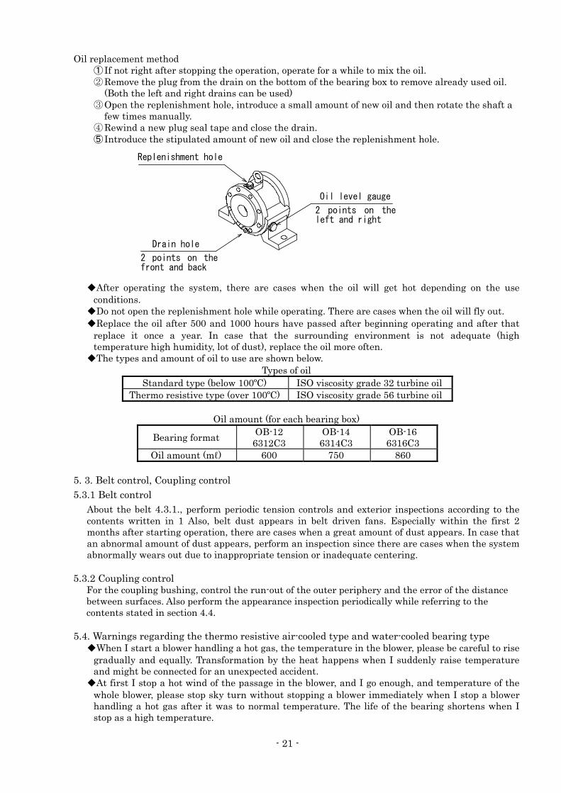
Oil replacement method ① If not right after stopping the operation, operate for a while to mix the oil. ② Remove the plug from the drain on the bottom of the bearing box to remove already used oil.
(Both the left and right drains can be used) ③ Open the replenishment hole, introduce a small amount of new oil and then rotate the shaft a
few times manually. ④ Rewind a new plug seal tape and close the drain. ⑤ Introduce the stipulated amount of new oil and close the replenishment hole.
◆After operating the system, there are cases when the oil will get hot depending on the use conditions.
◆Do not open the replenishment hole while operating. There are cases when the oil will fly out. ◆Replace the oil after 500 and 1000 hours have passed after beginning operating and after that
replace it once a year. In case that the surrounding environment is not adequate (high temperature high humidity, lot of dust), replace the oil more often.
◆The types and amount of oil to use are shown below. Types of oil
Standard type (below 100ºC) ISO viscosity grade 32 turbine oil Thermo resistive type (over 100ºC) ISO viscosity grade 56 turbine oil
Oil amount (for each bearing box)
Bearing format OB-12 6312C3
OB-14 6314C3
OB-16 6316C3
Oil amount (mℓ) 600 750 860 5. 3. Belt control, Coupling control
5.3.1 Belt control About the belt 4.3.1., perform periodic tension controls and exterior inspections according to the contents written in 1 Also, belt dust appears in belt driven fans. Especially within the first 2 months after starting operation, there are cases when a great amount of dust appears. In case that an abnormal amount of dust appears, perform an inspection since there are cases when the system abnormally wears out due to inappropriate tension or inadequate centering.
5.3.2 Coupling control
For the coupling bushing, control the run-out of the outer periphery and the error of the distance between surfaces. Also perform the appearance inspection periodically while referring to the contents stated in section 4.4.
5.4. Warnings regarding the thermo resistive air-cooled type and water-cooled bearing type
◆When I start a blower handling a hot gas, the temperature in the blower, please be careful to rise gradually and equally. Transformation by the heat happens when I suddenly raise temperature and might be connected for an unexpected accident.
◆At first I stop a hot wind of the passage in the blower, and I go enough, and temperature of the whole blower, please stop sky turn without stopping a blower immediately when I stop a blower handling a hot gas after it was to normal temperature. The life of the bearing shortens when I stop as a high temperature.
Oil level gauge
Replenishment hole
Drain hole
2 points on thefront and back
2 points on theleft and right
- 22 -
5. 5. Restart after stop or interruption In case of interrupting the operation for a long or short period of time, after cleaning the impeller and the inside of the system and conserve it after performing enough rustproof measures. (Same for outdoors) If the storage continues for a long period of time (more than 1 month), remove the V belts. Also, to prevent rust from getting to the bearing, remove the bearing guard once a month and manually idle the shaft (Exploded view schematic ④) rotating it about 10 times. When restarting the system, perform the same inspection than the ones made in an operational test. Specially check the following points ◆Is there any corrosion inside the impeller and casing? ◆Pull the plug and check there are no water accumulations inside the casing.
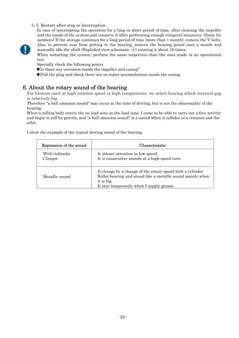
6. About the rotary sound of the bearing
For blowers used at high rotation speed or high temperature, we select bearing which internal gap is relatively big. Therefore "a ball omission sound" may occur at the time of driving, but is not the abnormality of the bearing. When a rolling body enters the no load zone at the load zone, I come to be able to carry out a free activity and begin to roll by gravity, and "a ball omission sound" is a sound when it collides in a retainer and the orbit. I show the example of the typical driving sound of the bearing.
Expression of the sound Characteristic
With ticktacks
Clangor
It attract attention in low speed. It is consecutive sounds at a high-speed turn
Metallic sound
It change by a change of the rotary speed with a cylinder Roller bearing and sound like a metallic sound mainly when it is big.
It stay temporarily when I supply grease.
- 23 -
7.Use of inverter (frequency converter) (1) Set the upper-limit frequency to the frequency stated on the nameplate or less.
(If the blower is used at a frequency exceeding that stated on the nameplate, it may be overloaded, causing burnout of the motor. Additionally, the centrifugal force may increase, causing the impeller to deform or break.)
(2) Different voltage
In a product with a different voltage (380 to 460 V), the surge voltage is high. This may cause damage to the insulation of the winding and malfunctioning of the product. For availability of custom-made products, be sure to contact us.
(3) Symptoms that may occur when the inverter is used.
1) Abnormal noise Abnormal noise can be reduced by changing the carrier frequency. In addition, be sure to follow the instruction manual for the inverter when operating the inverter. (Abnormal noise due to the use of an incorrect voltage waveform for the commercial power supply and the adverse effects of higher harmonics may occur during inverter operation.)
2) Resonance When the product is used in an environment with strong vibration, its service life may be shortened. Use the inverter while avoiding resonance points. (The blower resonates due to its natural frequency at a specific frequency and the vibration may become large.) The piping or installation method may be the cause of this symptom. The resonance may occur due to the piping method. For this reason, avoid direct piping as much as possible.
3) Temperature increase The temperature of the winding may increase during inverter operation when compared to the operation with a commercial power supply.
4) Start and stop The start time and stop time may become longer depending on the impeller's moment of inertia, causing tripping of the inverter. In addition, avoid rapid acceleration or deceleration as it may cause the motor to malfunction. (Change the inverter acceleration and deceleration time settings. If the acceleration time is short, over-current tripping may occur. If the deceleration time is short, over-voltage tripping due to regenerative current may occur.)
5) Air-cooling blower If the RPM of the cooling fan decreases in the air-cooling blower, the heat radiation may be
insufficient. (4) Other points
For details, see the instruction manual for your inverter.
- 24 -
6. Warranty Scope of warranty
Repair service is provided free of charge for a failure during the warranty period, as long as the blower has been used in compliance with these Operating Instructions, labels attached to the body, and other instructions. In the case that this product is incorporated into other equipment used by the customer, the warranty does not cover costs for removal from such equipment, reattachment to such equipment, costs of other incidental work, costs of transportation etc., resulting opportunity loss incurred by the customer, lost operation, or any other indirect loss or damage suffered by the customer. • For requests for repair service, please contact our nearest branch or sales office.
Warranty period One (1) year from the date of delivery of the product.
Even during the warranty period, only charged service is provided in principle, if any of the following applies:
• Failure or damage due to incorrect use that is not compliant with these Operating Instructions, labels attached to the body, or other instructions, and/or unauthorized repair or modification
• Failure or damage due to transportation, dropping, etc. after the purchase • Failure or damage due to fire, earthquake, storm, flood, lightening or other natural
disasters, environmental factors such as salt damage and public pollution, abnormal voltage, use of a power supply (voltage or frequency) other than that specified, or the like
• Failure or damage due to repair or modification (including punching, etc. in the product) not conducted by our company
• Failure or damage due to the use of parts other than those designated by our company • Failure or damage due to the entry of foreign material • Discoloration, scratching, natural consumption of consumable parts or other defects due
to use or deterioration over time • Failure or damage caused by neglecting the maintenance and inspection described in the
Operating Instructions
We will not compensate for any loss or damage resulting from defects that occur during the use of this product.
[Notices] (1) The descriptions in these Operating Instructions are subject to change without prior
notification in the future. (2) We have made all possible efforts to prepare these Operating Instructions. However, if
you have any questions about them or find any inquiries, errors, omissions, etc., please contact our nearest branch or sales office.
(3) If the power supply frequency changes due to a change in the location where the blower is used, it may not be used as it is. We will consider a measure in each case where it is required. In such a case, please contact our nearest branch or sales office.
(4) At the time of inquiry, please describe the product type and the manufacturing number indicated on the product nameplate.
- 25 -
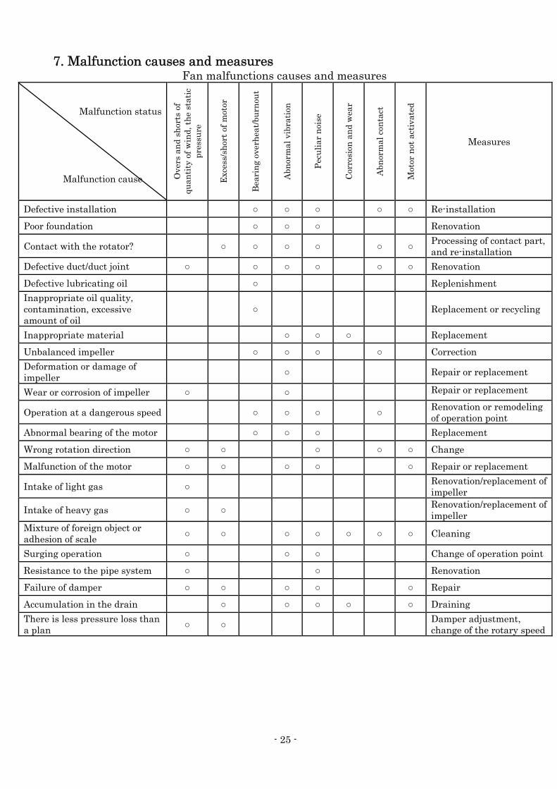
7. Malfunction causes and measures Fan malfunctions causes and measures
Malfunction status Malfunction cause O
vers
an
d sh
orts
of
quan
tity
of
win
d, t
he
stat
ic
pres
sure
Exc
ess/
shor
t of
mot
or
Bea
rin
g ov
erh
eat/
burn
out
Abn
orm
al v
ibra
tion
Pec
uli
ar n
oise
Cor
rosi
on a
nd
wea
r
Abn
orm
al c
onta
ct
Mot
or n
ot a
ctiv
ated
Measures
Defective installation ○ ○ ○ ○ ○ Re-installation
Poor foundation ○ ○ ○ Renovation
Contact with the rotator? ○ ○ ○ ○ ○ ○ Processing of contact part, and re-installation
Defective duct/duct joint ○ ○ ○ ○ ○ ○ Renovation
Defective lubricating oil ○ Replenishment
Inappropriate oil quality, contamination, excessive amount of oil
○ Replacement or recycling
Inappropriate material ○ ○ ○ Replacement
Unbalanced impeller ○ ○ ○ ○ Correction
Deformation or damage of impeller ○ Repair or replacement
Wear or corrosion of impeller ○ ○ Repair or replacement
Operation at a dangerous speed ○ ○ ○ ○ Renovation or remodeling of operation point
Abnormal bearing of the motor ○ ○ ○ Replacement
Wrong rotation direction ○ ○ ○ ○ ○ Change
Malfunction of the motor ○ ○ ○ ○ ○ Repair or replacement
Intake of light gas ○ Renovation/replacement of impeller
Intake of heavy gas ○ ○ Renovation/replacement of impeller
Mixture of foreign object or adhesion of scale ○ ○ ○ ○ ○ ○ ○ Cleaning
Surging operation ○ ○ ○ Change of operation point
Resistance to the pipe system ○ ○ Renovation
Failure of damper ○ ○ ○ ○ ○ Repair
Accumulation in the drain ○ ○ ○ ○ ○ Draining
There is less pressure loss than a plan ○ ○ Damper adjustment,
change of the rotary speed

Note on your purchased blower
Fan identification information that you may need when making an inquiry of us.
Model Serial No.
Purchased on Year/Month/Day Starting day Year/Month/Day
Distribution
agent TEL ( ) In charge:
SHOWA DENKI CO., LTD.
1-25 Shinden, Kita-machi, Daito City, Osaka 574-0052, Japan
http://www.showadenki.co.jp