familiarization • user operations • start-up • shutdown...
TRANSCRIPT

19XLCentrifugal Chiller
Control Systemwith Product
Integrated Controls (PIC)Service Training
Familiarization • User Operations • Start-up • Shutdown
Troubleshooting
The contents of the 19XL-01 Packaged Training Program, Catalog No. 021-901 are: one VHS
video, 138 35mm slides and this workbook, Catalog No. 021-900. This program covers:
"MANUFACTURER RESERVES THE RIGHT TO DISCONTINUE, MODIFY, OR CHANGE SPECIFICATIONS AND/OR DESIGNS AT ANY TIME WITHOUT NOTICE OR INCURRING OBLIGATION. THIS PROGRAM IS INTENDED FOR FAMIL-
IARIZATION AND/OR TRAINING PURPOSES ONLY AND SHOULD NOT BE CONSIDERED OR TREATED AS COMPLETE INSTALLATION, SERVICE, OR TROUBLESHOOTING REFERENCES FOR SUBJECT OR OTHER PRODUCTS. CURRENT
PRODUCT SPECIFIC INSTALLATION AND SERVICE LITERATURE SHOULD BE CONSULTED BEFORE ATTEMPTING THE PROCEDURES, PROCESSES, OR TECHNIQUES DESCRIBED HEREIN."
Copyright ©
Carrier Corporation 1993
®

ContentsMachine Familiarization
PIC Components
PIC Components & Circuitry
Inputs and Outputs
LID Screens
PIC User Operations
Status Function
Schedule Function
Setpoint Function
Service Function
Equipment Configuration
Equipment Service
Controls Test
Operating System Control
Machine Start-Up and Shutdown

ContentsTroubleshooting
Quiz
Quiz Key
Wiring Diagram A
Wiring Diagram B

Objectives:Upon completion of this training program, you will be familiar with the 19XL Centrifugal Chiller
with PIC Control and understand the operating sequences.
Presentation Instructions:1. Obtain necessary audio visual equipment, training aids, handout materials and program
workbooks for each participant.
2. View the video. A break is provided for review purposes. Use the slides to reinforce
important topics.
3. Distribute and review materials (see suggested list of additional materials below).
4. Administer quiz, then review using Slide/Page references noted in the Quiz Key.
5. Distributors may obtain Certificates of Achievement through Literature Distribution.
Additional Training Materials:1. 19XL Start-Up, Operation and Maintenance Instructions.
2. This 19XL book, Catalog No. 021-900.
Self Instruction:When using this program for self instruction, review the video tape, read the workbook in its
entirety, and complete the quiz. Quiz answers with paragraph references are located in the Quiz
Key.

Introduction
1. The primary purpose of this program is to familiarize you with the new 19XL centrifugal liquid
chiller controls. We will be covering the following subjects:
• Machine familiarization
• PIC controls features and functions
• PIC Components
• Inputs and outputs
• LID screens
• PIC user operations
• Operating system control
• Machine start-up and shutdown
At the conclusion of the program you should understand the operation of the controls, and how
to conduct a machine start-up.
Click here for Figure 1 — 19XL Centrifugal Chiller

Machine Familiarization
But first we want to introduce the unit features in this latest Carrier-designed chiller.
This centrifugal chiller will be introduced with a single-frame size of 300 to 600 tons. The 19XL is available with either HCFC-22 or HFC-134A refrigerants.
2. This 19XL Heat Exchanger is made for ease of service. Overall, the 19XL machine is designed for the replacement or retrofit market. It can be broken down into three pieces; cooler, condenser, and compressor. The cooler and condenser are bolted together and can be separated to fit into tight places.
3. The compressor is mounted on the cooler section and has lifting lugs for rigging, one on the motor and one on the compressor base. It also can be removed to make rigging into small spaces easier.
Gasketted flanges and "O" rings make disassembly and reassembly easy, eliminating any cutting and welding.
Click here for Figure 2 — 19XL Heat Exchanger
Click here for Figure 3 — 19XL Compressor

4. The compressor has flanged elbows on both the suction and discharge for easy servicing.
The 19XL is equipped with isolation valves; one valve between the condenser and the
discharge elbow and another valve under the cooler. A third valve is located in the motor
cooling refrigerant line.
These valves are used to isolate the refrigerant charge for service work. You can close the
valve located at the discharge elbow and the refrigerant cooling isolation valve.
5. Then push the liquid refrigerant out of the cooler and into the condenser using the optional
pumpout unit. When all the liquid refrigerant is transferred, the isolation valve under the cooler
is closed, and the pumpout unit is used to evacuate the gas from the cooler and compressor. To
speed up the transfer use the PIC controls. Go to the controls test function and use the
pumpout feature. This starts the condenser water pump and the cooler pump. It also directs you
through the entire pumpdown process and locks out the low pressure alarm and the
Click here for Figure 4 — Compressor (Flanged Elbows)
Click here for Figure 5 — Liquid Transfer

compressor from being started. Run the pumpout unit until it reaches as low a vacuum as
possible. Use the PIC display and the gauges to monitor the pressures. It is also possible to use
the pumpout unit to transfer the charge into the cooler/compressor to service the condenser.
6. A high-side float is used for refrigerant control. It is similar to a 19FA-style refrigerant float
that uncovers an orifice to maintain the proper liquid level. This is also flanged for easy service.
New-style machines will be equipped with a linear-style float valve.
7. An optional hot gas bypass is located on the bottom of the cooler. Hot condenser gas enters
the cooler through a solenoid valve which is piped up into the condenser. This valve is
controlled by the temperature difference or ∆T between the entering and leaving chilled water
and the pressure differential or ∆P between the cooler and condenser.
Click here for Figure 6 — 19XL High Side Float
Click here for Figure 7 — Hot Gas By-pass Option

8. Each vessel, cooler and condenser are ASME approved with relief valves, so that the
refrigerant may be safely isolated in either side of the machine. A pressure gauge is mounted
on the condenser along side the relief valves.
The cooler and condenser are available in 2 or 3 pass configurations. Inside the heat exchangers, the tubes are supported by two tube sheets and three support sheets.
The standard cooler tubes are high efficiency type with external nucleate boiling surface. The internal surface is spiral fin for maximum heat transfer. Standard condenser tubes are Spikefin, also with internal rifling.
Spikefin Tube: This tube derives from the conventional integral-finned tube where circumferential integral fins are notched to provide spikes. Surface tension controlled condensation occurs on these spikes and provides higher heat transfer coefficients. These tubes show lesser condensate retention and thus provide higher heat transfer coefficients when compared to integral-finned tubes.
The condenser has a baffle plate located under the compressor discharge ell to distribute the refrigerant over the condenser tubes. Remember, with R-22 we only have to move 20% as much refrigerant vapor CFM to get the same refrigerant effect as R-11. It also has a flash subcooler, similar to the 19DK machine, which subcools the refrigerant prior to entering the float chamber.
Click here for Figure 8 — 19XL Cooler Tubes

Diffuser
9. Next is the conical diffuser. The technology for this diffuser was derived from aerospace
technology used on Pratt & Whitney's jet aircraft engines. This diffuser is designed for high
efficiency and to operate in a very stable manner over a wide range of conditions. This diffuser
has built in surge protection and practically eliminates any need for a moveable diffuser wall or
hot gas bypass.
Notice this area on the diffuser wall. This is machined into a scalloped shape with a shallow
angle. The refrigerant leaving the impeller is channeled through this scalloped shape into the
conical diffuser. The refrigerant then follows Bernoulli's basic law of physics where the
refrigerant enters the conical channel at high velocity, low static and leaves at low velocity, high
static. Just the right conditions for a centrifugal chiller.
Click here for Figure 9 — Diffuser

Impeller
10. Now let's look at the impeller. This is an entirely new design. The 19XL machine uses a
single aluminum impeller. It is an open type impeller and the running speed is 16,000 RPM.
Notice how the fins sweep back to increase stability and raise efficiency. And, notice the splitter
blades; they make for more efficient compression with less chance of surge.
11. There are four drilled holes through the impeller that are used to reduce thrust. These
venting holes equalize the pressure on both sides of the impeller. Located in the back of the
impeller is a Labyrinth seal. This is used to counteract the thrust with suction pressure.
Click here for Figure 10 — 19XL Impeller
Click here for Figure 11 — 19XL Impeller (Drilled Holes)

Controls
12. As for controls, the 19XL machine is equipped with a product integrated control or a PIC and
will interface with the Carrier Comfort Network. Notice there are two boxes on this side of the
machine. On the back side, on the condenser, is a mounting for an optional starter, either
electromechanical or solid state.
13. The box in front of the oil pump is called the Power Panel. Part of the circuitry is high voltage
and contains contactors for the oil pump and oil heater. Also in the Power Panel are step-down
transformers to supply the low voltage needed for the PIC control box.
Click here for Figure 12 — Controls
Click here for Figure 13 — 19XL Power Panel

14. Here is the PIC control center. On the front we have a stop button, an alarm light, an LID and
four function switches or softkeys.
Inside the box we find a processor module known as the PSIO (Processor Sensor Input
Output). There is room enough to add four optional modules for future requirements. To the left
is a relay module. This entire box is low voltage and gets its power from the Power Panel.
The LID displays information both while the machine is running and during shutdown. Near the
top, there are two system messages displaying the operation mode. To the top right is the time
and date display and the compressor run time indicator. Under that we have nine blocks of
information which concern:
• Entering chilled water temperature
• Leaving chilled water temperature
• Evaporator refrigerant temperature
• Condenser water inlet temperature
• Condenser water leaving temperature
• Condenser refrigerant temperature
• Oil pressure
Click here for Figure 14 — 19XL PIC Control Center

• Oil sump temperature
• Percent motor current
Below, on the monitor, we find a display for each of the four softkeys. As we use these menu
functions, the nomenclatures and function of these four keys will change.
Sensors feed information to the PIC controls. These sensors are new and have a quick release
plug at the sensor for easy servicing.
There is one in the oil sump to monitor sump temperature, and also to control the oil heater.
There is one dual-element bearing sensor (one element is a spare). The terminal plate for the
high speed bearing sensor is located on the compressor base near the oil pump.
There are two sensors for motor temperature embedded in the stator windings (one is a spare).
The motor sensor terminal plate is located on the side of the stator near the motor terminal box.
15. There are two sensors in the compressor discharge. One is a pressure switch that opens on
high pressure. The other measures discharge gas temperature.
Click here for Figure 15 — 19XL Sensors (Compressor Discharge)

16. Sensors measure both entering and leaving chilled water. The condenser water circuit also
has sensors on both the entering and leaving water connections.
A temperature switch is embedded in the oil pump motor winding. Its terminals are on the oil
pump motor terminal plate. To measure oil pressure, there is a transducer in the oil pump
discharge. There is a transducer on top of the evaporator to measure evaporator refrigerant
pressure. There is another transducer on top of the condenser measuring condenser refrigerant
pressure there. The combination of all these thermistors and transducers relay information to
the PIC controls.
17. This unit is available with one of two types of factory-mounted optional starters.
Click here for Figure 16 — 19XL Sensors
Click here for Figure 17 — 19XL Optional Starters

18. One option is an electro-mechanical style starter. The controls on this starter include a
Starter Management Module or SMM to communicate with the PSIO in the PIC control box. The
control panel is hinged and swings out of the way to service the starter contacts.
19. The second type of starter available is solid state. The solid state starter is new to Carrier
centrifugals. This starter also uses a Starter Management Module, or SMM, to communicate
with the PSIO in the PIC control box. Amperage, voltage and operating information are relayed
between the PSIO and the SMM. This operating information can be displayed on the LID by
pushing the status function softkey.
Click here for Figure 18 — Electro-mechanical Style Starter
Click here for Figure 19 — 19XL Solid State Starter

Compressor
20. The 19XL compressor is a new design which utilizes the best of older designs and new technology. The suction guide vanes, used to control capacity, are chain driven, using a vane actuator motor.
21. Motor cooling is accomplished by piping liquid refrigerant from the bottom of the condenser through a valve, a filter-dryer and a sight glass to the motor end bell. To control the motor cooling process, there is a bypass line with a solenoid valve which will open to allow extra refrigerant into the motor during high load conditions. From there the refrigerant travels to a spray nozzle and is sprayed into the rotor and stator where it flashes and cools the motor.
The refrigerant level is maintained in the motor shell and overflows through a drain on the side of the motor shell to a back pressure valve located at the flanged drain connection. This back pressure valve is a spring check type and maintains a 5 to 7 lb. differential between the motor cavity and the cooler.
Click here for Figure 20 — 19XL Compressor
Click here for Figure 21 — 19XL Motor Cooling

22. To recover oil an eductor system is used which is similar to the one used on the 19D Series
machines.
High pressure gas piped from the compressor discharge is directed across an eductor. This
creates a low pressure area at the eductor which, in turn, is connected to the suction housing.
Oil is normally carried with the refrigerant into the suction housing. However, an additional line
from the cooler to the suction housing ensures that oil travels into the housing. The refrigerant
and oil are then transferred through a line and filter into the oil reservoir. The refrigerant flashes
to a gas and returns to the system through the demister and vent line located between the
transmission housing and suction elbow. This keeps the transmission at suction pressure. The
vent at the transmission housing uses a demister pad similar to the 19D Series. The oil then
drops into the oil reservoir.
A check valve prevents the oil from flowing backward during shutdown.
During light load conditions, the guide vane actuator closes a switch which energizes two
solenoids. Because of the low suction pressure, the eductor will now take suction directly from
the cooler shell in order to return the oil.
Click here for Figure 22 — 19XL Oil Recovery System

23. Notice how the oil pump is located in the transmission housing -- not directly under the
motor, but offset to one side.
The oil pump motor is 3 phase and the pump is a positive displacement vane type. The 19XL
machine has a 10 gallon oil capacity and uses a new synthetic oil.
The oil cooler is located outside of the oil pump housing and uses liquid refrigerant to cool the
oil.
A thermostatic expansion valve controls the refrigerant flow and maintains the oil temperature.
The compressor housing is both the oil reservoir and sump. There are two sight glasses for the
oil, and the operating oil level should be maintained between the two. The shutdown level
should be somewhere between the top of the bottom glass and the middle of the upper glass.
Typical oil pressure is 20 to 25 lbs differential pressure.
Click here for Figure 23 — Oil Pump/Transmission Housing

24. Pressurized oil is supplied to compressor bearings and gears by an internally mounted,
electric motor driven, vane type pump, which is submerged in the oil reservoir.
Oil from the pump discharge passes through the oil pump motor and serves as a coolant. Oil
pressure is regulated by a relief valve that is located internally. The valve relieves the pump
discharge back into the oil sump, maintaining proper oil system pressure. Pressurized oil then
passes from the pump motor housing and into the filter chamber via some external piping. After
being filtered, the oil is piped to the external oil cooler. Notice the valving on the oil filter. These
two valves enable the service technician to isolate the oil filter and change it without draining the
entire oil sump or having to pull the refrigerant charge. A charging valve is located on the filter
housing to drain the oil in the filter chamber and also to evacuate and recharge new oil.
The pressurized oil flows to the transmission assembly where it feeds two lines. The lower line
supplies oil to the high speed thrust bearing assembly and lubricates the gears. The upper line
supplies the low speed shaft bearings. From there the oil is channeled to the high speed shaft
bearing nearest the pinion. The oil then drains to a sump at the base of the compressor
housing.
Click here for Figure 24 — 19XL Lubrication System

25. The oil heater is a new design with 1200 Watts. The oil heater has a flanged terminal plate
with a flat washer-type gasket. The oil heater is controlled by a thermistor with its sensor
immersed in the oil sump. The oil temperature in the sump is maintained between 140 and
160°F depending upon what the evaporator refrigerant temperature is.
Click here for Figure 25 — 19XL Oil Heater

PIC Components
26. Now, let's identify the components. At the top of the control panel is the Local Interface
Device (LID), which contains a Liquid Crystal Display (LCD). Input and output information
appears on this screen. To the left of the LID is the alarm light and the Stop button.
Immediately below the screen are four "softkeys," whose functions vary with the particular
screen being displayed. In every display, the bottom line on the screen will identify the function
of the softkeys.
27. Inside the panel we have the processor module (PSIO), a six-pack relay module, a power
supply, and four circuit breakers. One or two additional 8-input modules can be installed for
reset options, spare temperature sensors, or applications with a CCN network. The controls are
powered by two of the transformers we saw earlier in the power panel.
Click here for Figure 26 — 19XL Local Interface Device (LID)
Click here for Figure 27 — 19XL Processor Module

28. The local interface device displays information both while the machine is running and during
shutdown. These controls will:
• Control start-up and shutdown of the chiller.
• Modulate the compressor guide vanes to maintain desired chilled water temperature, and to protect against abnormal compressor conditions.
• Generate alarm and alert messages for abnormal conditions, and shut down the machine when system safety requires.
• Control unit operation per the programmed occupied/unoccupied schedules.
• Provide testing of all inputs and outputs.
• Display all input and output data.
• Provide compatibility with CCN systems.
Click here for Figure 28 — 19XL Local Interface Device

29. The starter management module (SMM), the power panel and the control panel make up the
Product Integrated Control (PIC). These are microprocessor based devices that control
machine operation and perform diagnostic functions, using inputs from the machine and the
operator. The remainder of this program will be spent learning how these devices function and
how to use them.
30. Before we get into detail on the PIC controls, it might be helpful to compare the PIC system
with the 32MP system that you may be familiar with. To begin with, both systems provide start-
up and operational control, a controls test, and considerable diagnostics. Both control the same
basic and optional unit functions, and both systems use similar 5K ohm thermistors.
Click here for Figure 29 — 19XL Product Integrated Control (PIC)
Click here for Figure 30 — 32MP System

31. The advantage of PIC is that it is a system with modified keypad entry and display screen,
simplifying inputs and enabling messages rather than codes to be displayed to the user. Gone
are the potentiometer calibration inputs of the 32MP, replaced by precise keypad inputs in PIC.
And the dip switches are no longer required, thanks to the keypad inputs. PIC can also read
transducer inputs, so system pressures can be monitored. And, of course, PIC can interface
with the Carrier CCN network and the Building Supervisor, well beyond the scope of the 32MP.
Click here for Figure 31 — 32MP vs. PIC

PIC Components and Circuitry
32. The PIC consists of three panels which contain the major control components. The three
individual panels mentioned are the control panel, power panel, and Starter Management
Module (SMM). Located within the control panel are the processor module (PSIO), local
interface device (LID), 6-pack relay board, and options module.
33. The PSIO contains all of the operating software needed to control the machine. Connected
to the PSIO module are three pressure transducers and eight temperature thermistors. There
are also outputs to the guide vane actuator, and the 6-pack relay board for control of: oil pump,
oil heater, hot gas bypass, motor cooling solenoid valve, and spare alarm contact. The PSIO
communicates with the LID and SMM for user interface and starter management.
Click here for Figure 32 — PIC Components and Circuitry
Click here for Figure 33 — PSIO Module

34. The LID is mounted on the front panel of the control center and is used by the operator to
interface with PIC. It is the input center for all machine setpoints, operating schedules, setup
functions and options. The lid has a large display screen, an alarm light, a stop button and four
buttons for logic input. The function of the four buttons or "soft keys" is always shown on the
bottom or menu line of the display screen.
35. The 6-pack relay is located within the control panel and is used as a pilot relay, when
energized by the PSIO, to operate the oil pump, oil heater, spare alarm, optional HGBP valve,
and motor cooling solenoid valve.
Click here for Figure 34 — LID Mount
Click here for Figure 35 — 6-pack Relay Board

36. The option modules, when present, are factory or field installed in the control panel. There
could be one or two of these modules installed, each with up to eight spare inputs available. It is
used whenever chilled water reset, demand reset, or for reading any spare temperature sensor.
The sensors are field installed.
37. The power panel contains the HGBP relay, control transformers, oil pump terminal block,
voltage selection switch and contactors for the oil heater and oil pump.
38. The oil pump contactor operates the oil pump at rated voltage per the job requirement. The
PIC energizes the contactor to operate the oil pump as necessary during machine start-up,
operation and shutdown. The oil heater contactor is controlled by the PSIO and 6-pack relay
board to maintain proper oil temperatures during machine shutdown.
Click here for Figure 36 — Option Modules
Click here for Figure 37 — Power Panel
Click here for Figure 38 — Oil Pump Contactor

39. The hot gas bypass relay controls the opening of the hot gas bypass valve. The PIC
energizes the relay during low load, high lift operating conditions.
40. The control transformers convert incoming control voltage to either 21V or 24V supply power
for the PSIO module, the three power panel contactor relays, the guide vane actuator, and the
options module.
41. It is possible to utilize either 115 or 230 volt incoming control power in the power panel. The
voltage selector switch is set for a particular application.
Click here for Figure 39 — Hot Gas Bypass Relay
Click here for Figure 40 — Control Transformers
Click here for Figure 41 — Control Circuit Voltage Selector

42. The Starter Management Module (SMM) is always located within the starter panel. The
starter can be unit mounted or remotely located.
43. This SMM initiates PSIO commands for starter functions such as starting/stopping the:
compressor, condenser and chilled water pumps, tower fans, spare alarm contacts, and the
shunt trip. The SMM monitors starter inputs such as flow switches, remote start contact, spare
safety, condenser high pressure, oil pump interlock, motor current signal, starter 1CR and RUN
contacts, and KW transducer input. The SMM also contains programming to safely stop the
machine if communications from the PSIO are lost.
Click here for Figure 42 — Starter Management Module
Click here for Figure 43 — Starter Management Module (PSIO)

44. Main 115V or 230V single-phase power for the controls is fed from the starter panel to the
power panel transformers through the voltage selection switch. This power also feeds the oil
heater when the 1C contacts are closed. Transformer T1 provides 21-volt power to the 5-volt
transformer, in the control panel, used to power the condenser, evaporator and oil pressure
transducers. T1 also powers the PSIO module and the LID.
45. Transformer T2 provides 24V control power to the oil heat contactor (1C), oil pump contactor
(2C), and HGBP relay (3C) and oil recovery solenoids. Of course, these items are powered only
when the PSIO sends the proper signals to the 6-pack relay board pilot relays K1, K2, K4 and
K5. Note also that the oil pump contactor cannot function unless the oil pump motor winding
temperature safeties are closed.
Click here for Figure 44 — Transformer (T1)
Click here for Figure 45 — Transformer (T2)

46. Transformer T3 powers the compressor guide vane actuator to open and close the guide
vanes as signals are received from the PSIO. The actuator operates on 24 volts.
47. Transformer T4 supplies 21 volts to the 8 input options module. Option modules are always
required if the machine has Auto Demand Reset Option or Auto Chill Water Reset Option. It
may also be required if a Chillervisor Lead/Lag system is installed. It also has optional inputs for
five additional temperature inputs. All of the inputs to the module must be field installed. These
inputs are communicated to the PSIO and the LID.
Click here for Figure 46 — Transformer (T3)
Click here for Figure 47 — Transformer (T4)

48. As mentioned, the Starter Panel contains the Starter Management Module (SMM). The
SMM receives its power from a 115V to 24 VAC transformer. Inputs monitored by the SMM
include contact closures for remote start, evaporator and condenser water flows, and a spare
safety contact. It also checks the closure of the IM auxiliary contact, motor run, condenser high
pressure and oil pump auxiliary contacts.
49. Tied in series with the condenser high pressure safety and oil pump auxiliary contacts are
the starter fault contacts and 1CR control coil. Motor output is measured by a current
transformer input to indicate motor amperage. Available as an option is a 4-20mA kilowatt
transducer to measure motor power. Also measured is motor voltage which uses a 24-volt
transformer with a trim potentiometer. The voltage measured to the motor should equal the
voltage read on the STATUS01 screen. Adjust the trim POT to set the voltage on the LID
screen.
Click here for Figure 48 — Starter Panel
Click here for Figure 49 — Starter Fault Contacts

50. The SMM also outputs signals to the chilled water pump, condenser water pump, tower
fans, shunt trip and alarm pilot relay control coils through communication with the PIC.
Click here for Figure 50 — Starter Management Module

Inputs and Outputs
51. Inputs supply system information to the controls so that proper control decisions can be
made. The input devices may be thermistors for measuring temperature, transducers for
measuring pressure, contacts that supply or interrupt voltage, or dry contacts whose condition
will be sensed by the controls. The PSIO has several inputs, located at the J7 terminals. The
three pressure inputs are:
• Condenser refrigerant pressure
• Evaporator refrigerant pressure, and
• Oil pressure.
Temperature inputs include:
• Entering chilled water temperature
• Leaving chilled water temperature
• Compressor discharge temperature
• Thrust bearing temperature
Click here for Figure 51 — Inputs Supply System

• Oil sump temperature
• Compressor motor winding temperature
• Condenser entering water temperature
• Condenser leaving water temperature
• Stop push button/Voltage reference
52. Outputs are signals to report information or cause system controls to operate. The PSIO
outputs are at the J6 terminals and provide signals to the 6-pack relay board. Some examples
of outputs are:
• Guide vane operation
• Oil heater relay
• Motor cooling solenoid
• Oil pump relay
• Hot gas bypass relay
• Alarm relay
Click here for Figure 52 — Outputs

53. Each 8-input module has two 4-20 mA inputs and six spare temperature inputs. The 4-20
milliampere inputs can be internally or externally powered.
The number 1 8-input module has the following inputs:
• Auto demand reset
• Auto chilled water reset
• Common chilled water supply temperature
• Common chilled water return temperature
• Remote temperature reset
• Remaining 3 input are spare temperatures
The number 2 8-input module has two spare 4-20 mA inputs and 6 spare temperature inputs.
54. The Starter Management Module (SMM) also has inputs and outputs, for control of system
start-up and shutdown. These inputs might include:
Click here for Figure 53 — 8-Input Module
Click here for Figure 54 — Starter Management Module (SMM)

• Chilled water flow switch
• Condenser water flow switch
• Compressor start auxiliary contacts
• Compressor run auxiliary contact
• Spare protection contacts
• Starter fault
• Remote Contacts
• Compressor motor amps
• Line voltage monitor
55. The SMM outputs control pilot relays in the starter for the
• 1CR compressor start relay
• Chilled water pump relay
• Condenser water pump relay
• Tower fan relay
• Shunt trip relay
• Alarm relay
Click here for Figure 55 — SMM Outputs Control

56. Let's briefly discuss what the PIC controls can do.
These controls:
• Start-up and shutdown the chiller including controlling some timing functions associ-ated with the starter.
• Modulate the compressor inlet guide vanes to maintain the leaving chilled water tem-perature and limit the power consumed by the motor.
• Override the guide vane position control in response to low refrigerant temperature, high motor temperature, high motor current, manual guide vane control, high com-pressor lift, or condenser high pressure.
• Generate alerts, such as high bearing temperature, or high discharge temperature.
• Provide surge protection by shutting the compressor off based on a number of spe-cific changes in motor current over a time period. This can be configured in the equip-ment service function.
• Provide protection against high compressor discharge temperature.
Click here for Figure 56 — PIC Controls
Click here for Figure 57 — Guide Vane Position Control
57.

• Protect the chiller from damage by monitoring certain control inputs and executing a safety shutdown if required.
• Provide full compatibility with the ChillervisorTM system manager and other CCN devices.
• Allows readability of all PIC points and provides the capability of "Writing" to certain points with a CCN network.
• Will display via the LID all input and output data.
Click here for Figure 58 — PIC Controls
58.

LID Screens
59. The LID (Local Interface Device) is used by the operator to access operating, service, and
maintenance data for the chiller. With the LID, you can perform operations such as viewing and
adjusting setpoints and schedules, viewing and modifying configuration and service data,
viewing alarm history, or checking chiller status.
60. A variety of displays (screens) are available at the LID. If no other specific display has been
called for, then the default screen is displayed. This provides basic information on machine
operation, such as chilled water and condenser water temperatures, refrigerant saturated
temperatures, oil pressure and temperature, etc.
Click here for Figure 59 — Local Interface Device (LID)
Click here for Figure 60 — Default Screen

61. Notice the bottom line of data. Every screen uses the bottom line to identify the function of
the softkeys. In this case, the left key puts the machine under CCN control, the next is for
LOCAL control, the next for RESET of alarms, and the last is for the MENU.
62. Depressing the MENU softkey brings up a new screen, whose bottom line identifies the
softkey functions of STATUS, SCHEDULE, SETPOINT, and SERVICE. Each of these is a
section of the software devoted to those specific functions, and is accessed by depressing the
appropriate softkey.
The STATUS function provides information on the status of the machine, and provides
capability for changing certain points or conditions. The SCHEDULE function is for entering or
viewing the on/off schedule. The SETPOINT function is for entering or viewing the system
setpoints, and the SERVICE function deals with configuration data, service, and controls
testing.
Click here for Figure 61 — Function of the Soft Keys
Click here for Figure 62 — Depressing Menu Soft Key

63. The STATUS function has three screens. The first displays status of control points and
sensors. The second STATUS screen displays status of relays and contacts. The third STATUS
screen displays the status of options module sensors.
64. Likewise, the SCHEDULE function has several screens relating to the machine start/stop
schedule, and the SETPOINT function has one screen displaying the system setpoints. The
SERVICE function has a variety of screens relating to equipment configuration, alarm history,
controls test, system maintenance, and so on.
Click here for Figure 63 — STATUS Function
Click here for Figure 64 — SCHEDULE Function

PIC User Operations
65. Now that we have seen what the controls consist of, and reviewed their basic functions, it is
time to see what happens as we operate them. First we will make sure that we have control
circuit power to the transformers, and all the circuit breakers are closed, which will power up the
controls.
66. When the controls power up, the LID performs several diagnostic tests to insure that it is
functioning properly, and that it is correctly connected to the chiller. If the diagnostics are
successful, the default screen will then be displayed.
Click here for Figure 65 — Control Circuit Power
Click here for Figure 66 — Default Screen Display (Diagnostics)

67. The default screen provides basic information on the chiller operation, as well as alert and
alarm messages. This screen appears whenever you exit any of the PIC operations, or
whenever the LID has been left on another display for 15 minutes. In the upper left hand corner,
the primary and secondary chiller messages are shown. In this example, the machine is running
under normal temperature and in the occupied mode. In the right hand corner are the date,
time, and length of time the machine has been running. The default screen data is updated
every 2 to 5 seconds.
68. The center of the default screen displays the status of the following points:
• CHW IN Entering chilled water temp
• CHW OUT Leaving chilled water temp
• EVAP REF Evaporator refrigerant temp
Click here for Figure 67 — Default Screen
Click here for Figure 68 — Default Screen Displays

Throughout this program, you will hear the terms "point" or "points." Points are pieces of
information which are part of the controls data base. It can be an input or output; for example:
pressure or temperature, or a derived value such as motor current.
69. There are two other terms we would like to define: Alert and Alarm. An ALERT is an
abnormal condition that generates a warning message. It may delay start-up, but is not serious
enough to cause shutdown of an operating machine. Let's pick an example where the machine
fails to start. In the upper left hand corner the primary message is PRESTART ALERT, and
below this the secondary message stating the reason - LOW OIL TEMPERATURE. A point in
• CDW IN Entering condenser water temp
• CDW OUT Leaving condenser water temp
• COND REF Condenser pressure
• OIL PRESS Oil pressure
• OIL TEMP Oil sump temperature
• MTR AMPS Percent of compressor motor current
Click here for Figure 69 — Prestart Display

alert will be blinking about once a second, and in our example, the display OIL TEMPERATURE
will be blinking. As soon as the oil temperature rises above setpoint, the start-up process will
resume automatically.
70. An ALARM is an abnormal condition serious enough to prevent start-up or to cause
automatic shutdown of an operating machine. If a point is in alarm, its value switches back and
forth between the normal condition and the actual abnormal condition. Let's say COND REF
(condenser pressure) is in alarm. First, notice the message in the upper left corner of the
screen. Here we see protective limits and the reason is HIGH CONDENSER PRESSURE. And
at the right side of the screen the point COND REF will be alternating between the normal value
and the highlighted actual value. The cause of the high condenser pressure must be corrected,
and the RESET key must be pressed to remove the alarm in order for the machine to start.
Click here for Figure 70 — Alarm and Reset Key

Status Function
71. Now we will leave the default screen by depressing the MENU key, which brings up the
choices of STATUS, SCHEDULE, SETPOINT, and SERVICE. We will press the STATUS key,
and a list of the three status screens is displayed - STATUS01, 02 and 03. Note that the softkey
functions are now NEXT, PREVIOUS, SELECT, and EXIT. The top line, STATUS01, is
highlighted. If we wanted to look at that screen, we would simply press SELECT. If we wanted
to look at STATUS03, we would press NEXT until STATUS03 is highlighted. After highlighting
STATUS03, if we wanted to go back to STATUS02, we could press PREVIOUS.
72. The three status screens display specific types of information:
• STATUS01 shows the status of the pressure and temperature sensors and control settings
• STATUS02 shows the status of the relays and contacts (either on or off)
• STATUS03 shows the status of the option modules sensors
Click here for Figure 71 — STATUS, SCHEDULE, SETPOINT, and SERVICE
Click here for Figure 72 — Status Screens

73. When you select one of the tables on the Status Table Select screen, the Point Status
Screen appears. Remember, points are pieces of information which are part of the controls data
base. This screen displays the current value of the points in the selected table. Shown here is a
typical point status screen for STATUS01. Each status line consists of four pieces of
information: the point's name, its value, its units, and its status.
74. The last position of the status line tells you the point's status. If an asterisk (*) appears, the
point is in alarm. In this example, condenser refrigerant temperature is in alarm. If a "C" appears
in the status position, a communication failure has occurred, as in this example of remote
contact input. A blank in the status position indicates that the point is normal and an
exclamation point (!) indicates the value is in an alert condition.
Click here for Figure 73 — Status Table Select Screen
Click here for Figure 74 — Status Line

On some screens like the Point Status Screen, all of the items will not fit on one screen at a
time. By pressing the NEXT or PREVIOUS keys the highlight will scroll downward or upward to
highlight the various points.
75. Some points are allowed to be changed or modified by the operator, and this is called an
"override". To do this, first select the point to be modified by using the NEXT or PREVIOUS
keys on the Point Status screen to highlight the desired point. Then press the SELECT key and
two things will occur. MODIFY POINT will appear in the upper right corner of the screen, and
the bottom line will show new names for the softkeys.
The INCREASE and DECREASE keys are used to raise or lower the point value. Each time
either of these keys is pressed, the value of the last digit of the point will change by one
increment. If the INCREASE or DECREASE key is held for more than five seconds, the value of
the second digit changes by one for each second the key is held.
Click here for Figure 75 — Point Override

76. If the selected point is start/stop or release, the softkey functions will be renamed to START/STOP/RELEASE and ENTER.
77. If the point is an On or Off type, then the softkeys are renamed ON, OFF, RELEASE and ENTER. The control will not permit a point to be overridden to an OFF state. After you change the value or state of a point, the ENTER key must be pressed to register the new value. Then you can select another point to be modified, or press EXIT twice to return to the default screen. Each press of the exit key will back you up a screen.
78. Points that have been overridden will display the type of override next to the point's value. SUPVSR, BEST, or SERVICE will appear to indicate there is an override. To remove an override, select the point as before, and press the RELEASE key.
Click here for Figure 76 — START/STOP/RELEASE and ENTER
Click here for Figure 77 — ON, OFF, RELEASE and ENTER
Click here for Figure 78 — SUPVSR, BEST or SERVICE

79. What happens if you try to change a point that is not allowed to be overridden? Fortunately,
you cannot "crash" the system that easily. The controls simply will not let the point change. For
example, if we tried to change Leaving Condenser Water, which is not allowed to be overridden,
we would highlight the point on the STATUS01 screen, and as soon as we pressed the
SELECT key we would get a message CANNOT CONTROL SELECTED POINT. You then get
to EXIT gracefully, without embarrassment!
80. If we highlight Target Guide Vane Position and press the select key, its value can be raised
or lowered using the INCREASE/DECREASE keys as required to obtain the new value.
Remember to press the ENTER key after the new value is set to save this value. To release the
override when finished, press RELEASE.
Click here for Figure 79 — Points Unable to be Overridden
Click here for Figure 80 — Target Guide Vane Position

81. Press the EXIT key to bring up the Status Table Select Screen and highlight the STATUS02
line using the NEXT key. Press the SELECT key, and STATUS02 screen appears. The items
on this screen are discrete points. For example: highlight Tower Fan Relay press SELECT, and
turn it on using the ON key. Be sure to press the ENTER key to save the required point value.
The RELEASE key will bring the point back to automatic control. Because the tower fan is an
important machine control point, the controls will not allow the fan to be overridden "OFF". It can
only be ON or in the automatic mode.
82. If we were to proceed to the STATUS03 screen, you would find it contains all of the 19XL 8-
input module points. All of the items on this screen are able to be overridden.
Click here for Figure 81 — Status Table Select Screen
Click here for Figure 82 — STATUS03 Screen

83. Now let's recap the STATUS function keystrokes.
• At the default screen, press MENU.
• At the menu screen, press STATUS.
• Select the proper status screen by using NEXT or PREVIOUS to highlight the desired screen, and press SELECT.
• View the desired point by using NEXT or PREVIOUS to highlight the point.
• Press SELECT to choose the desired point to override
• Use the softkey functions to change the point's value or state.
• Press ENTER to register the new value or state.
• Press EXIT until you return to the default screen.
Click here for Figure 83 — Status Function Keystrokes

Schedule Function
84. The schedule function defines the occupied (on) and unoccupied (off) periods for the
system, and is accessed in the same way as the status function. At the default screen, press
MENU and at the menu screen press SCHEDULE. This brings up a schedule select screen
containing two choices: OCCPC01S and OCCPC02S. OCCPC01S is used whenever the unit is
started in the local mode, and OCCPC02S is used whenever the unit is used in CCN mode.
Press SELECT to bring up the period select screen, which lists all of the periods. Scroll to
highlight the desired period and press SELECT to modify the period.
85. Up to eight periods may be configured for our machine. Often only two are necessary; one
for weekdays and one for weekends. We will be defining each period by selecting a start time
and stop time, and then assigning the desired days of the week to each period. The start and
stop times must be entered in 24-hour military time.
Click here for Figure 84 — Schedule Function
Click here for Figure 85 — Period Definition

86. Now let's work through an example. Suppose we want to set up an occupied schedule for
6:15 a.m. to 6:30 p.m. on Mondays through Fridays. On the period select screen we will
highlight PERIOD 1 and press the SELECT key. Notice that the hour portion of the ON time is
highlighted. We will use the INCREASE/DECREASE keys to set the ON hours to 06. Pressing
ENTER will register the new value and move the highlight to the minutes. We will set the ON
minutes by using the INCREASE key to display 15, and press ENTER to register the value and
the highlight will move to the OFF hours. We will use the INCREASE/ DECREASE keys as
before to set the OFF hours to 18 and the OFF minutes to 30. Then, pressing ENTER will
register the values and highlight the first day of the week.
87. When the highlight moved to the days of the week, the softkey identification changed to
ENABLE, DISABLE, ENTER, and EXIT. Days of the week with an X are selected; days of the
week with a blank are disabled. Pressing ENABLE places an X under the highlighted day of the
Click here for Figure 86 — Example (Period Selection)
Click here for Figure 87 — ENABLE, DISABLE, ENTER and EXIT
week, which will cause the system to start at the ON time and shutdown at the OFF time on that
day. Pressing DISABLE will cause the ON and OFF times to be ignored on the highlighted day.
Since we want period 1 to apply to Monday through Friday, but not the weekend, we will press
ENABLE for Monday and then press ENTER to register the condition and move the highlight to
Tuesday. We will move through the weekdays in the same manner.
When finished with period 1, we can EXIT to the period select screen and set up any additional
periods required. Scheduling for holiday periods will be covered later in the SERVICE Function.
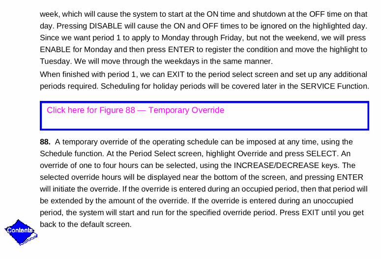
88. A temporary override of the operating schedule can be imposed at any time, using the
Schedule function. At the Period Select screen, highlight Override and press SELECT. An
override of one to four hours can be selected, using the INCREASE/DECREASE keys. The
selected override hours will be displayed near the bottom of the screen, and pressing ENTER
will initiate the override. If the override is entered during an occupied period, then that period will
be extended by the amount of the override. If the override is entered during an unoccupied
period, the system will start and run for the specified override period. Press EXIT until you get
back to the default screen.
Click here for Figure 88 — Temporary Override

Setpoint Function
89. SETPOINT is used to view or modify the system setpoints. There are only three setpoints:
Base demand limit, Leaving chilled water, and Entering chilled water. Only one of the chilled
water setpoints can be active, and this choice is configured in the SERVICE function. The
controls are factory configured with the leaving chilled water setpoint active.
90. The SETPOINT function is accessed from the default screen in the same manner as
STATUS and SCHEDULE. At the default screen press MENU, then press SETPOINT, and you
can view the three points. If you wish to modify a point, press NEXT or PREVIOUS to highlight
the desired setpoint, and press SELECT to activate the override screen.
Click here for Figure 89 — SETPOINT Function
Click here for Figure 90 — SETPOINT Function Access

91. Modifying a setpoint uses the same techniques we have already learned. When we went to
the override screen, the softkey labels became INCREASE, DECREASE, QUIT and ENTER.
Simply press the INCREASE or DECREASE keys to raise or lower the value, and then press
ENTER to register the value. This will also return you to the previous screen, where you can
EXIT to the default screen. As before, holding the INCREASE or DECREASE keys down
increases the rate at which the value changes.
92. Let's run through an example. Suppose we wish to change the leaving chilled water setpoint
to 58° F. Starting at the default screen, we press MENU, then SETPOINT, then use NEXT to
highlight Leaving Chilled Water, then press SELECT. The displayed value is 55.0° F. To
change it to 58.0° F, we depress the INCREASE key until 58.0 is displayed. When 58 is
reached, we press ENTER to register the value.
Click here for Figure 91 — Modifying a Setpoint
Click here for Figure 92 — Example

93. QUIT is an escape key. If you increase or decrease a setpoint value and then decide not to
change it, pressing QUIT will leave the setpoint at its original value and return you to the
previous screen. There are limits established for each setpoint, and if you should attempt to
change a setpoint beyond its allowed limit, you will get a message LIMIT EXCEEDED at the
bottom of the screen. Then press QUIT, then EXIT to return to the default screen.
Click here for Figure 93 — QUIT/Escape Key

Service FunctionNow we will look at some of the SERVICE function operations. Some of the things you can do in
the service function are:
• Check the alarm history file
• Perform controls tests
• Check current state of various control algorithms
• View and modify equipment configuration data
• Set equipment service variables
• Set time and date
• Communicate with other CCN devices
• Log out of device
• View and modify the controller ID table
• Configure the LID
We will cover only five of the items, which may be needed for initial system setup or routine
servicing.

94. The SERVICE function is password protected to prevent unauthorized changes. At the
default screen, press MENU and at the menu screen press SERVICE. This brings up the
password screen, and you must enter the 4 digit password in order to access the service
screen. The softkeys represent the numbers 1, 2, 3, and 4, and when pressed in the proper
sequence, the service screen will appear. If a specific password has not already been
programmed, then the default password of 1111 will apply.
95. At the service screen, we see a variety of choices available. Using the NEXT or PREVIOUS
keys, we will move the highlight to TIME AND DATE and press SELECT, which brings up a new
screen. We can now use the INCREASE OR DECREASE keys to set the correct time and date,
pressing ENTER to register the values, and then EXIT to the service screen.
Click here for Figure 94 — Service/Function Password
Click here for Figure 95 — Time and Date Selection

96. As an example, let's say it is now 3:30 p.m. on Wednesday, January 13, 1993, and we want
to enter that into the controls. Highlight TIME AND DATE, and press SELECT to bring time and
date up on the screen. The highlight is on HOURS, and we will set the time as we did in the
schedule example, using INCREASE to advance the hours display to 15. Then we will press
enter to register the value and highlight minutes. Now we will use INCREASE to advance the
minutes display to 30, press ENTER, and the highlight moves to date. Now we will use the
increase and decrease keys to select the DATE, 1 for January, then press ENTER, 13, ENTER,
93, ENTER, and the date is registered. Once the date is entered, use the increase and
decrease keys to change to the correct day of the week, WEDNESDAY. The last line of data
shows whether the present date has been programmed as a holiday. Holiday scheduling will be
covered shortly. Now we will complete the example by pressing EXIT to return to the service
screen.
Click here for Figure 96 — Service Function Example

97. Now let's look at ALARM HISTORY, which will let us view up to 25 alarms and alerts. At the
service screen we will highlight ALARM HISTORY, and press SELECT, which will bring up the
alarm history screen. Wait 6 seconds for the alarm table to update, then the most recent alarm
or alert will be at the top of the screen with a time and date stamp to identify them, and the
NEXT or PREVIOUS key can be used to scroll to any alarms that are off screen. The EXIT key
will return us to the service screen.
Click here for Figure 97 — Alarm History

Equipment ConfigurationNext we will look at EQUIPMENT CONFIGURATION. This is where various options are
enabled or disabled, and setpoints entered to define the operation of each option. The
configuration table contains the following options, which are accessed from the configuration
table select screen:
• Chilled water reset (3 types)
• Return/Leaving water control
• Pulldown rate
• Auto restart
• Remote contacts option
• Demand limit
98. As an example, suppose we wanted to change the chilled water control from leaving water
to return water. Starting at the service screen, we use the NEXT or PREVIOUS keys to highlight
EQUIPMENT CONFIGURATION. Pressing the SELECT key brings up the configuration table
select screen, and we will use the NEXT or PREVIOUS keys to highlight Entering Chilled Water
Control, also known as the Return Chilled Water Control. The controls are factory supplied with
Click here for Figure 98 — Equipment Configuration

the return water control disabled, which by default causes the machine to control from leaving
water. So if we want to change to return water control, we press the SELECT key, and enable
the function by pressing the ENABLE key. If we change our mind and then want to disable it, we
can do that by pressing the DISABLE key. Then we can return to the service screen using the
EXIT key.
99. Another function you may need to know about is Holiday Scheduling, which allows an
operating schedule (defined in the SCHEDULE function) to be applied to up to 18 holiday
periods. Starting at the equipment configuration screen, scroll to highlight HOLIDEF, and press
SELECT to bring up the data table select screen. Then we will use the NEXT key to highlight
the desired holiday table. Each table is one holiday period, starting on a specific date, and
lasting up to 99 days.
Click here for Figure 99 — Holiday Scheduling

100. Now we will press SELECT to access the first holiday table, and the screen now shows the
holiday start month and day, and the number of days the first holiday period will last. There are
no factory-programmed holidays, so they will have to be done as part of an initial start-up.
Now press SELECT, then we will use the INCREASE or DECREASE keys to change the value
of each line of data, pressing ENTER to register each new value. The numbers 1 through 12
represent the months. For example, if we entered the value 1 in each of the three lines, that
would define January 1 as a one day holiday. Now we can return to the default screen by using
the EXIT keys. And back at the SCHEDULE function, the particular schedule to be applied to
the holiday periods is identified by entering an "H" at the end of the Days-of-the-Week field, then
press ENABLE and then press ENTER to add the holiday.
Click here for Figure 100 — Holiday Table

Equipment Service
101. Another area that may require field input is in the Equipment SERVICE function. This is used to view or modify the configuration of the chiller service tables. Starting at the SERVICE screen, scroll to highlight EQUIPMENT SERVICE, and press SELECT to bring up the Table Select screen. There are three choices on this screen: SERVICE1 contains the basic operating configuration points and defines alert and override conditions, SERVICE2 defines alert conditions for the optional 8-input modules, and SERVICE3 contains the guide vane's algorithm proportional and gain values.
102. We are interested mainly in screen 1, so press SELECT to bring up the list of configuration points. We want to make sure that all items are correct for our application. Changes can be made as previously described, if necessary. Some examples of the variables you will find in the SERVICE1 screen are:
• Motor temperature override with default of (200° F).• Condenser pressure override (195 psi).• Refrigerant override ∆T (2° F), and so on.
Click here for Figure 101 — Equipment Service Function
Click here for Figure 102 — SERVICE1 Variables

Controls Test
103. Now we will cover one of the most useful functions, the Controls Test. This can be done in
a variety of ways by making selections from the Controls Test menu. The Automated Test is a
comprehensive test of all inputs and outputs for proper values and/or operation. The chiller
must be off to run this test − press the stop button to put the chiller in the off mode. Each part of
the test will ask the operator to confirm that the specific operation is happening and whether or
not to continue to the next function. If an error occurs, the operator can either fix the problem
before continuing or proceed with the test. When the final test is complete, pressing the EXIT
key will return the screen to the Controls Test menu.
By selecting other items from the menu, you can accomplish the following:
• PSIO Thermistor - Check of all PSIO thermistors.
• Options Thermistors - Check of all option board thermistors.
• Transducers - Check of all transducers.
• Guide Vane Actuator - Check of the actuator and guide vane operation.
• Pumps - Check output of pumps. The pumps can be activated all together or individ-ually. This test confirms associated input, such as flows or pressures.
• Discrete Outputs - Checks all ON/OFF outputs, together or individually.
Click here for Figure 103 — Controls Test

• Pumpdown - To pumpdown refrigerant from unit. It shows the proper sequence to follow, locks compressor off and starts water pumps during the evacuation.
• Terminate Lockout - Enables chiller to run after pumpdown lockout. It instructs the operator as to the proper sequence to follow.
If a bad reading should occur during any tests that are not automated, an asterisk will appear
next to that reading.
104. To run the controls tests, start at the SERVICE screen and scroll to highlight CONTROL
TEST. Press SELECT to bring up the controls test menu, and scroll to highlight the desired test.
Press SELECT and the selected test will begin.
105. For example, if we wanted to check our pumps, we would scroll down to PUMPS on the
controls test screen. Press SELECT, then decide all or individual. We will select all. Now the
test begins and the screen displays the message PUMPS TEST IN PROGRESS. And when
each pump is found to be OK, the message FLOW CONFIRMED appears. If a pump was found
Click here for Figure 104 — Running Controls Test
Click here for Figure 105 — Pump Check

each pump is found to be OK, the message FLOW CONFIRMED appears. If a pump was found
to be bad, the message FLOW NOT CONFIRMED would appear. There will be a question,
DEACTIVATE ALL PUMPS NOW? Press YES. It then displays PUMPS TEST COMPLETE.
When finished, the EXIT key will return us to the Control Test Select screen, and pressing it
again returns us to the SERVICE screen.
106. Returning to the SERVICE SCREEN highlight and select CONTROL ALGORITHM
STATUS. When this item is chosen, a MAINTENANCE TABLE SELECT screen with menu
appears.
Selecting any of the MAINT01, 02 or 03 tables provides a MAINTENANCE SELECT screen
where you can view the values of items listed. MAINT01 is the capacity control algorithm.
MAINT02 presents override status and MAINT03 shows surge and hot gas bypass status.
Also listed on the MAINTENANCE TABLE SELECT is the OCCDEFM or time schedule status
for LOCAL and CCN control.
Click here for Figure 106 — Maintenance Table Select

107. When you select this item for viewing a DATA TABLE SELECT screen presents a menu
from which you would select topic items to view or change. The SELECT soft key would provide
a MAINTENANCE SELECT screen with the appropriate information available for viewing.
108. Now, let's exit back to the SERVICE SCREEN and select LID CONFIGURATION. This
menu item when selected presents a LID CONFIGURATION screen. From this screen we can
elect to modify the LID CCN address, pick US or metric units of measure, and change the
LOGON to SERVICE password. Now exit back to the SERVICE screen.
109. To password protect the SERVICE function, log off from the SERVICE function. Simply use
the EXIT key to return to the service menu, then highlight LOG OUT OF DEVICE, press
Click here for Figure 107 — Data Table Select
Click here for Figure 108 — LID Configuration
Click here for Figure 109 — LOG OUT OF DEVICE

SELECT, and the default screen will come up. An alternative to logging out is to simply do
nothing. If the controls sense no activity for 15 minutes, they will automatically log you off and
return to the default screen. Once this procedure is performed, the password menu will appear
the next time the SERVICE menu is accessed.
That concludes the fundamentals of user operation. Before we go through a typical start-up and
shutdown procedure, let's make sure we understand what the controls are doing during
machine operation. Remember that we earlier said that the controls generate alarms and alerts,
and control chilled water temperature. They also provide diagnostic data and controls testing
capability, and tell the unit when to run, and how to start up and shut down.

Operating System Control
110. Now let's look at how the chilled water temperature is controlled. The PSIO receives inputs
from both the entering and leaving chilled water thermistors, and as we saw earlier, one of
these will have been selected as the control point. As long as the actual chilled water
temperature is stabilized above the setpoint (desired) temperature, the machine will load up and
operate continuously during the occupied condition.
111. When the chilled water temperature starts to drop, the controls will cause the compressor
guide vanes to move toward the closed position, which reduces the amount of refrigerant
pumped by the compressor. The rate at which the compressor is unloaded depends on how far
we are from the setpoint, and how fast the water temperature is dropping.
Click here for Figure 110 — Operating System Control
Click here for Figure 111 — Compressor Guide Vanes

112. The guide vanes vary the compressor capacity. When the vanes are in the fully unloaded
position, the compressor is at approximately 10% of its full load capacity. And in the fully loaded
position, of course, the compressor is at 100% capacity.
113. The PSIO will keep adjusting the guide vanes position until the capacity of the compressor
causes the chilled water temperature to equal the setpoint. The guide vanes are driven from the
actuator motor.
114. If the guide vanes are at the unloaded or closed position and the chilled water temperature
still goes 5° F. below setpoint, the machine will go into a Recycle mode. In Recycle, the controls
will cycle the machine through automatic shutdowns and start-ups to maintain the chilled water
Click here for Figure 112 — Capacity Control
Click here for Figure 113 — Compressor Capacity
Click here for Figure 114 — Recycle Mode

temperature. Of course, if hot gas bypass has been specified, that will be activated as the load
drops below the minimum configured conditions, reducing the probability of having to go into
Recycle.
115. Capacity overrides can prevent some safety shutdowns caused by: exceeding motor
amperage limit, refrigerant low temperature safety limit, motor high temperature safety limit,
compressor high lift (surge protection), and condenser high pressure limit. In all cases there are
two stages of compressor vane control.
• The vanes are held from opening further, and the status line on the LID indicates the reason for the override.
• The vanes are closed until condition decreases below the first step setpoint, and then the vanes are released to normal capacity control.
Whenever the motor current demand limit setpoint is reached, it activates a capacity override,
again with a two-step process. Exceeding 110% of the rated load amps for more than 30
seconds will initiate the safety shutdown.
The surge prevention setpoint will cause a capacity override, as well. When the surge
prevention setpoint is reached, the controller normally will CLOSE the guide vanes. If so
Click here for Figure 115 — Capacity Overrides

equipped, the hot gas bypass valve will open instead of closing the vanes.
High discharge temperature override takes effect if the discharge temperature increases above
180° F. The guide vanes are proportionally opened to increase gas flow through the
compressor. If the leaving chilled water temperature is then brought 5° F below the Leaving
Chilled Water control temperature, the controls will bring the machine into the recycle mode.
116. There are two operating modes that should be mentioned. The first is Temperature Reset,
which temporarily raises or lowers the chilled water control point. This is a means of saving
energy by not producing water that is any cooler than necessary. Temperature reset can be
triggered by a remote temperature, a remote 4-20 mA input, or by the water temperature
differential across the cooler. Temperature reset is configured in the Equipment Configuration
portion of the SERVICE function. The machine's chilled water control is the same as for normal
running, except the control point is temporarily increased or decreased.
Click here for Figure 116 — Temperature Reset

117. The other operating mode we should be aware of is Automatic Demand Limit. This is
simply a means to limit the power drawn by the compressor, to avoid excessive electrical
service charges during high use periods. Demand limit is initiated by a schedule that activates
during the high cost time periods. The controls reduce the compressor load to a preset level,
using the guide vanes and monitoring motor current. Automatic demand limit is configured in
the Equipment Configuration portion of the SERVICE function. Control of the chilled water
temperature may be temporarily lost when demand limit is active, due to the limit imposed on
the compressor power.
118. One of the important functions of the PIC controls is to protect the machine from damage
when abnormal conditions occur. Typically, an ALERT is issued when a protective limit is
approached, and an ALARM and machine shutdown occurs if the protective limit is exceeded.
The following limits are a few examples of those monitored during machine operation:
Click here for Figure 117 — Automatic Demand Limit
Click here for Figure 118 — ALERT/ALARM Function

• High or low line voltage.
• High discharge temperature.
• High motor winding temperature.
• Low evaporator refrigerant temperature, and so on.
In general, the values assigned to these protective limits are preset, and are not field
adjustable. Limits related to compressor motor amps and low temperature brine operation can
be field modified.
119. The controls will attempt to avoid alarm conditions due to high motor temperature, high
discharge temperature, low evaporator refrigerant temperature, and high condenser pressure.
They do this by initiating a two step override on the compressor guide vanes, as the protective
limits are approached. The first step is a "hold", which simply prevents the guide vanes from
loading up any further. If the condition continues to worsen, then the second step causes the
guide vanes to unload until the condition improves past the point where the first step was
initiated. At that time the guide vanes are released from the override and will respond to normal
capacity signals.
Click here for Figure 119 — Step Override

Machine Start-Up and Shutdown
Now let's see what happens during an actual start-up and shutdown. We will assume that all the
required field-supplied control data has been entered, and that an occupied schedule has been
set up for the present time. Further, there is a very important and comprehensive pre-start
checklist that must be executed before doing an initial start-up, and we will assume that has
been completed. We will also assume that we have a stand-alone unit, not connected to a CCN
network.
120. A local or manual start-up is initiated by pressing the LOCAL key at the default screen. In
order for the start-up to proceed, an occupied mode must be specified for present time (or
unoccupied mode overridden), at least 3 minutes must have elapsed since the last shutdown,
and at least 15 minutes must have elapsed since the last start-up. And there cannot have been
more than eight starts in the last 12 hours. If remote contacts are enabled, then the contact
status determines if the start-up process continues. When those conditions are met, the
controls will perform a series of pre-start checks to verify that all safeties are within limits.
Click here for Figure 120 — Local Start-up

121. It is easier to visualize the start-up and shutdown sequences if we look at the control
sequence chart. Point A is when the LOCAL key is pressed and the safeties check performed.
122. If the safeties are OK, then the chilled water pump is started, and 5 seconds later (Point B)
the condenser water pump is started.
123. One minute later (Point C) the controls monitor the chilled water and condenser water flow
switches, and will wait up to 5 minutes if necessary to confirm the flow. The 5-minute wait time
can be modified, if desired, in the equipment service function. After the water flow is verified, the
tower fans are started, if the condenser pressure is high enough, and then the chilled water
temperature is compared to both the setpoint and deadband. If the water temperature is lower
Click here for Figure 121 — Control Sequence Chart
Click here for Figure 122 — Chilled Water Pump Started (Point B)
Click here for Figure 123 — Monitoring Flow Switches

than both, the condenser pump will be shut off and the machine will go into recycle mode.
If the chilled water temperature is high enough, the start-up sequence continues on to check the
guide vane position. If the guide vanes are more than 6% open, the start-up waits until the PIC
closes the vanes. If the vanes are closed, and the oil pump pressure is less than 3 psi, the oil
pump relay will then be energized.
124. Then (Point D), the PIC waits until the oil pressure is verified with minimum pressure of 15
psi.
125. After oil pressure is verified, the PIC waits 15 seconds and then the compressor start relay
(1CR) is energized to start the compressor (Point E.) At this point, the 15-minute start-to-start
timer is activated.
Click here for Figure 124 — PIC (Oil Pressure Verification)
Click here for Figure 125 — Compressor Start Relay

126. Once the system is up and running, the Ramp Loading function takes over. This is simply a
means to limit the electrical demand and possible motor overloading by controlling the rate at
which the chilled water temperature is pulled down, or the rate at which the motor amps build
up. Temperature pulldown is accomplished by temporarily modifying the chilled water setpoint
upward, and gradually decreasing it while the compressor capacity control adjusts accordingly.
Once the chilled water temperature reaches its normal setpoint, Ramp Loading is terminated.
During normal running or start-up, there are many status messages that can appear at the LID.
Some of these are:
• TIMEOUT — Waiting for timers to time out.
• READY — Timeouts completed, machine off for other reasons.
• RECYCLE — Shut down due to low load.
• START-UP — Normal start-up in progress.
• RAMPING — Pulldown limits in effect.
• RUNNING — Normal run mode.
• OVERRIDE — Running with an override active.
• DEMAND — Demand limit active.
Click here for Figure 126 — Ramp Loading Function

• ABNORMAL — Emergency run mode.
• TRIPOUT — Shutdown due to fault condition.
Shutdown of the machine can occur for a variety of reasons:
• The STOP button has been pressed.
• Machine is RECYCLING to maintain chilled water temperature.
• Time schedule has moved to unoccupied mode.
• A protective limit has been reached and the machine is in ALARM.
• The start/stop status has been overridden at the LID or CCN network.
• Power failure.
• Remote contacts have opened.
127. When a stop signal occurs (Point F) the shutdown sequence first stops the compressor by
de-activating the start relay (1CR). At this point, the 3-minute stop-to-start timer is activated.
Click here for Figure 127 — Stop Signal Occurrence

128. Sixty seconds after the compressor shuts down (Point G,) the tower fans, oil pump and
chilled water and condenser water pumps are shut down. However, if the condenser pressure
or temperature is high, the condenser water pump and the tower fan may continue to run.
129. A RECYCLE shutdown is an automatic shutdown when the compressor is already at
minimum capacity, and the chilled water temperature has dropped 5o F. below setpoint and
deadband. It is the same sequence as the manual shutdown just described, except the chilled
water pump remains running so the chilled water temperature can be monitored. When the
chilled water temperature rises, in this example, to setpoint plus 5° F, the machine will
automatically initiate a normal start-up, as described earlier.
Click here for Figure 128 — Compressor Shutdown
Click here for Figure 129 — Recycle Shutdown

130. A safety shutdown is identical to a manual shutdown, except the LID will display the reason
for shutdown, the alarm light will blink continuously, and the spare alarm contacts will be
energized. A safety shutdown requires that the RESET key be pressed in order to clear the
alarm and allow a machine start-up. Once the alarm is cleared, the LOCAL key must be
pressed to initiate start-up.
131. If it is desired that a machine automatically restart when power is restored after a power
interruption, AUTO RESTART in the Equipment Configuration function should be enabled.
Then, when the line voltage returns to within 10% of nominal, the guide vanes have closed and
an oil pump pre-lube has occurred, and all other start conditions are met, the machine will
automatically go through the normal start-up process.
Click here for Figure 130 — Safety Shutdown
Click here for Figure 131 — Auto Restart

Troubleshooting
132. The first thing to check when troubleshooting is the LID display. If the alarm light is flashing, check the primary and secondary message lines on the LID default screen. These messages will tell where the fault is occurring. The Alarm History table on the LID SERVICE menu will also carry an alarm message to further expand on this alarm. For a complete listing of messages, see the Start-Up, Operation and Maintenance Instructions.
133. The Control Test we mentioned earlier is another troubleshooting feature that can check out all of the thermistor temperature sensors, including those on the Options modules, pressure transducers, pumps and their associated flow switches, guide vane actuator, and other control outputs, such as hot gas bypass. The tests can help to determine whether a switch is defective, or a pump relay is not operating, among other useful troubleshooting tests. During pumpdown operations, the pumps are energized to prevent a freeze-up and the vessel pressures and temperatures are displayed. The lockout feature will prevent start-up of the compressor when no refrigerant is in the machine, or the vessels are isolated.
Click here for Figure 132 — Troubleshooting (LID Display)
Click here for Figure 133 — Control Test

134. The Processor module (PSIO), 8-input (Options) modules, Starter Management Module
(SMM), and the Local Interface Device (LID) module perform continuous self diagnostic
evaluations. Proper operation of all modules is indicated by LEDs (Light Emitting Diodes)
located on the side of the LID, and on the top horizontal surface of the PSIO, SMM, and 8-input
modules.
135. Red LEDs blinking continuously at 1-second intervals indicates proper operation. If it is lit
continuously, a problem exists which requires replacement of the module. If the light is off, the
power supply should be checked. Lack of input power could be caused by a blown fuse as a
result of either a shorted transformer or a bad module.
Click here for Figure 134 — PSIO, SMM, LID (Self Diagnostics)
Click here for Figure 135 — Red LEDs (Proper Operation)

136. Green LEDs should always be blinking when the power is on. This indicates
intercommunications between modules and proper operation. If the green LED is not blinking,
check the red LED.
If a green LED is on solid and not blinking, check the communication wiring. If a green LED is
off, check the red LED. If the red LED is normal, check the module's communications wiring.
137. If a communications failure is indicated by all the modules, check the communication plug
(COMM) on the PSIO module. If properly seated and a good connection is assured but the
condition persists, replace the PSIO module. When a SMM or the LID indicates a
communications malfunction, again, check the COMM plug at the module. If the problem
continues, change the module.
Now a word of caution, if you are replacing a PSIO module, make sure the new PSIO has the
correct software to match your machine. The service replacement part number can be found on
the PSIO module label.
Click here for Figure 136 — Green LEDs (Power On)
Click here for Figure 137 — Communications Plug

If replacing a SMM or an 8-input module, check the address switches. The module address switch information can be found in the Service Instructions.
None of the modules can be field repaired.
Whenever a module is non-functional, it must be replaced.
If a PSIO is to be replaced, the new PSIO must be reconfigured to the original machine data. A CCN Building Supervisor or a Service Tool can be used to download the machine's configuration into the new PSIO, unless the software has been upgraded from the previous module. The configuration can always be manually modified.
138. Now we will talk about the transformers. If the power plugs are in place, secure and in good
condition, but the modules are not working, we would check the transformers. First check the
primary to see if power is available, then check the secondary. The transformer output voltage
can be checked at the module power plug terminal screws. We are looking for 21 volts on
everything but the SMM, which is 24 volts.
The transformers are located within the power panel, with the exception of the SMM, which has
its own transformer located within the starter.
If everything appears OK, perform normal troubleshooting procedures which would include
checking the relays and the thermistor sensor circuits.
Click here for Figure 138 — Transformers

This concludes the PIC controls familiarization program for the 19XL centrifugal chillers. You
should now have a good grasp of what the controls are, how they function, and how to use
them. Because of their extreme complexity and versatility, there are many controls functions
and details that we have not dealt with in this program. Further information will be found in the
machine Installation, Start-up and Service Instructions, and in the CCN Application Manual.

19XL PIC Chiller Quiz
1. True or False? The video monitor (LID) displays information only when the machine is
running.
2. The four keys below the LID are called _______________ keys.
3. True or False? The starter management module (SMM) is used with both the solid state
starter and the electro-mechanical starter.
4. Liquid refrigerant is used to cool both the _______________ and _______________.
5. Normal lube oil pressure is _______________ differential.
a. 15 - 20
b. 20 - 25
c. 40 - 45
6. Normal lube oil temperature is ______________° F.
a. 120 - 140
b. 140 - 160
c. 160 - 180
7. The _______________ contains all the operating software needed to control the machine.
8. Operator access to the PIC controls is provided by the _______________.

9. On/off control of the motor cooling solenoid, oil heater, oil pump, alarm contact and hot gas
bypass valve is provided by the _______________ _______________.
10. The chilled water pump relay and condenser water pump relay are controlled by the
_______________.
11. The LID screen that appears when no other screen has been specified is called the
_______________ screen.
a. primary
b. functional
c. default
12. True or False? The function of the four keys below the LID varies depending on the screen
displayed.
13. A displayed point that is blinking on the default screen indicates that the point is in
_______________.
a. alert
b. alarm
c. override

14. If an asterisk follows a point on the status screen, it indicates that the point is
_______________.
a. in alert
b. in alarm
c. a setpoint
d. overridden
15. The _______________ key is used to release alarms and allow normal operation of the
machine after the alarm conditions have been corrected.
16. The _______________ key is used to remove a forced or override condition.
17. The only software function that requires a password is the _______________ function.
a. STATUS
b. SCHEDULE
c. SETPOINT
d. SERVICE
18. True or False? The controls test can be conducted whenever the compressor is running.
19. In order for the machine to start, at least _______________ minutes must have elapsed
since the last shutdown, and at least _______________ minutes must have elapsed since the
last start-up.

20. True or False? Ramp loading is a means for limiting electrical demand by limiting the rate
at which the chilled water temperature is pulled down.
21. Normal operation of the PIC modules would be indicated when the red LEDs are
_______________.
a. on continuously
b. off
c. blinking
22. True or False? If the green LED on a PIC module is on continuously, it indicates a fault in
the communications circuit.

Quiz Key
Answer Paragraph No. 1. False 28
2. soft 26
3. True 18, 19
4. motor, lube oil 21, 23
5. b 23
6. b 25
7. PSIO processor module 33
8. LID (Local Interface Device) 59
9. six pack relay 35, 52
10. SMM (Starter Management Module) 43, 55
11. c 60
12. True 26
13. a 69
14. b 74
15. RESET 70
16. RELEASE 80

Answer Paragraph No.17. d 94
18. False 103
19. 3, 15 120
20. True 126
21. c 135
22. True 136

Wiring Diagram A

Wiring Diagram B

Figure 1 — 19XL Centrifugal Chiller

Figure 2 — 19XL Heat Exchanger

Figure 3 — 19XL Compressor

Figure 4 — Compressor (Flanged Elbows)

Figure 5 — Liquid Transfer

Figure 6 — 19XL High Side Float

Figure 7 — Hot Gas By-Pass Option

Figure 8 — 19XL Cooler Tubes

Figure 9 — Diffuser

Figure 10 — 19XL Impeller

Figure 11 — 19XL Impeller (Drilled Holes)

Figure 12 — Controls

Figure 13 — 19XL Power Panel

Figure 14 — 19XL PIC Control Center

Figure 15 — 19XL Sensors (Compressor Discharge)

Figure 16 — 19XL Sensors

Figure 17 — 19XL Optional Starters

Figure 18 — Electro-mechanical Style Starter

Figure 19 — 19XL Solid State Starter

Figure 20 — 19XL Compressor

Figure 21 — 19XL Motor Cooling

Figure 22 — 19XL Oil Recovery System

Figure 23 — Oil Pump/Transmission Housing

Figure 24 — 19XL Lubrication System

Figure 25 — 19XL Oil Heater

Figure 26 — 19XL Local Interface Device (LID)

Figure 27 — 19XL Processor Module

Figure 28 — 19XL Local Interface Device

Figure 29 — 19XL Product Integrated Control (PIC)

Figure 30 — 32MP System

Figure 31 — 32MP vs. PIC

Figure 32 — PIC Components and Circuitry

Figure 33 — PSIO Module

Figure 34 — LID Mount

Figure 35 — 6-pack Relay Board

Figure 36 — Option Modules

Figure 37 — Power Panel

Figure 38 — Oil Pump Contactor

Figure 39 — Hot Gas Bypass Relay

Figure 40 — Control Transformers

Figure 41 — Control Circuit Voltage Selector

Figure 42 — Starter Mangement Module

Figure 43 — Starter Management Module (PSIO)

Figure 44 — Transformer (T1)

Figure 45 — Transformer (T2)

Figure 46 — Transformer (T3)

Figure 47 — Transformer (T4)

Figure 48 — Starter Panel

Figure 49 — Starter Fault Contacts

Figure 50 — Starter Management Module

Figure 51 — Inputs Supply System

Figure 52 — Outputs

Figure 53 — 8-Input Module

Figure 54 — Starter Management Module (SMM)

Figure 55 — SMM Outputs Control

Figure 56 — PIC Controls

Figure 57 — Guide Vane Position Control

Figure 58 — PIC Controls
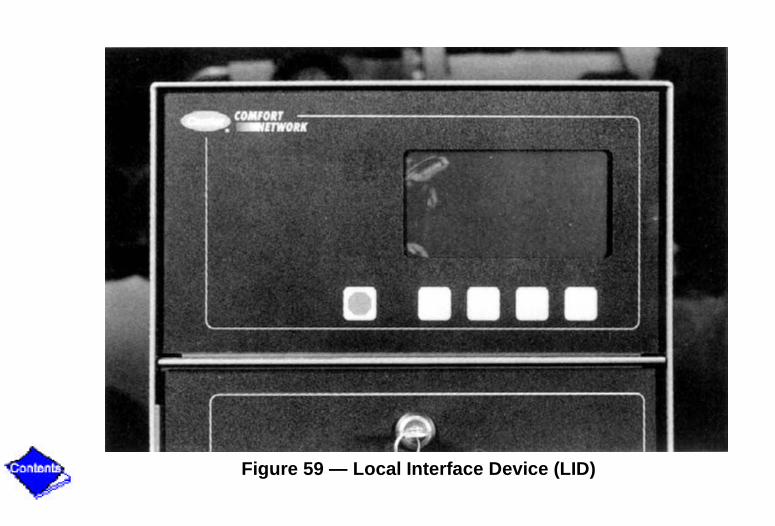
Figure 59 — Local Interface Device (LID)

Figure 60 — Default Screen

Figure 61 — Function of the Soft Keys

Figure 62 — Depressing Menu Soft Key

Figure 63 — STATUS Function

Figure 64 — SCHEDULE Function

Figure 65 — Control Circuit Power

Figure 66 — Default Screen Display (Diagnostics)

Figure 67 — Default Screen

Figure 68 — Default Screen Displays

Figure 69 — Prestart Display

Figure 70 — Alarm and Reset Key

Figure 71 — STATUS, SCHEDULE, SETPOINT and SERVICE

Figure 72 — Status Screens

Figure 73 — Status Table Select Screen

Figure 74 — Status Line

Figure 75 — Point Override

Figure 76 — START/STOP/RELEASE and ENTER

Figure 77 — ON, OFF, RELEASE and ENTER

Figure 78 — SUPVSR, BEST or SERVICE

Figure 79 — Points Unable to be Overridden

Figure 80 — Target Guide Vane Position

Figure 81 — Status Table Select Screen

Figure 82 — STATUS03 Screen

Figure 83 — Status Function Keystrokes

Figure 84 — Schedule Function

Figure 85 — Period Definition

Figure 86 — Example (Period Selection)

Figure 87 — Enable, Disable, Enter and Exit

Figure 88 — Temporary Override

Figure 89 — Setpoint Function

Figure 90 — SETPOINT Function Access

Figure 91 — Modifying a Setpoint

Figure 92 — Example

Figure 93 — QUIT/Escape Key

Figure 94 — Service/Function Password

Figure 95 — Time and Date Selection

Figure 96 — Service Function Example

Figure 97 — Alarm History

Figure 98 — Equipment Configuration
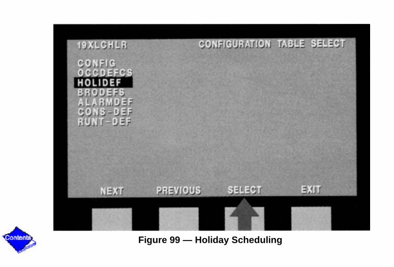
Figure 99 — Holiday Scheduling

Figure 100 — Holiday Table

Figure 101 — Equipment Service Function

Figure 102 — SERVICE1 Variables

Figure 103 — Controls Test

Figure 104 — Running Controls Test

Figure 105 — Pump Check

Figure 106 — Maintenance Table Select

Figure 107 — Data Table Select

Figure 108 — LID Configuration

Figure 109 — LOG OUT OF DEVICE

Figure 110 — Operating System Control

Figure 111 — Compressor Guide Vanes

Figure 112 — Capacity Control

Figure 113 — Compressor Capacity

Figure 114 — Recycle Mode

Figure 115 — Capacity Overrides

Figure 116 — Temperature Reset

Figure 117 — Automatic Demand Limit

Figure 118 — ALERT/ALARM Function

Figure 119 — Step Override

Figure 120 — Local Start-up

Figure 121 — Control Sequence Chart

Figure 122 — Chilled Water Pump Started (Point B)

Figure 123 — Monitoring Flow Switches

Figure 124 — PIC (Oil Pressure Verification)

Figure 125 — Compressor Start Relay

Figure 126 — Ramp Loading Function

Figure 127 — Stop Signal Occurrence

Figure 128 — Compressor Shutdown

Figure 129 — Recycle Shutdown

Figure 130 — Safety Shutdown

Figure 131 — Auto Restart

Figure 132 — Troubleshooting (LID Display)

Figure 133 — Control Test

Figure 134 — PSIO, SMM, LID (Self Diagnostics)

Figure 135 — Red LEDs (Proper Operation)

Figure 136 — Green LEDs (Power On)

Figure 137 — Communications Plug

Figure 138 — Transformers