faizan ulla khan, v.v. subrahmanayam, s. usha, v ... indira gandhi center for atomic research...
TRANSCRIPT
Faizan Ulla Khan, V.V. Subrahmanayam, S. Usha, V. Balasubramaniyan, P.Puthiyavinayagam
INDIRA GANDHI CENTER FOR ATOMIC RESEARCH
DEPARTMENT OF ATOMIC ENERGY
INDIA

• WHY SFR IN INDIA
• STATUS OF INDIAN SFR
• SFR & WASTE REDUCTION
• RADIOACTIVE WASTE MANAGEMENT IN SFR
• CLOSING OF FUEL CYCLE
• FUEL CYCLE FOR SUSTAINABLE RAD WASTE MANAGEMENT IN INDIA
• SUMMARY
• PROPOSAL FOR INPRO METHODOLOGY
2
WHY SFR IN INDIA
• Dr. Homi Bhaba devised India's three-stage nuclear power program in 1954. It was formulated to provide energy security to India. The main aim was to capitalize on India’s vast thorium reserves while accounting for its low uranium reserves. India has only about 2% of the global uranium reserves but 25% of the world’s thorium reserves.
• The three stages are: • Natural uranium fuelled Pressurized Heavy Water
Reactors (PWHR) • Fast Breeder Reactors (FBRs) utilizing plutonium based
fuel • Advanced nuclear power systems for utilization of
thorium
3

THREE STAGES OF INDIAN NUCLEAR POWER PROGRAMME
STAGE 1 STAGE 2 STAGE 3
U-233
ELECTRICITY
Depleted U
Pu
40000 Gwe- y Pu FUELLED
FAST BREEDERS
Th
155000 Gwe-y
ELECTRICITY U-233 FUELLED
REACTORS
Natural Uranium
ELECTRICITY PHWR
300 GWe-y
Th
Pu
U-233
4
*40 MWth FBTR, 1985 *500MWe PFBR commissioning
*30 KWth KAMINI,1996 *300MWe AHWR under development * Kalpakkam Unique in the world
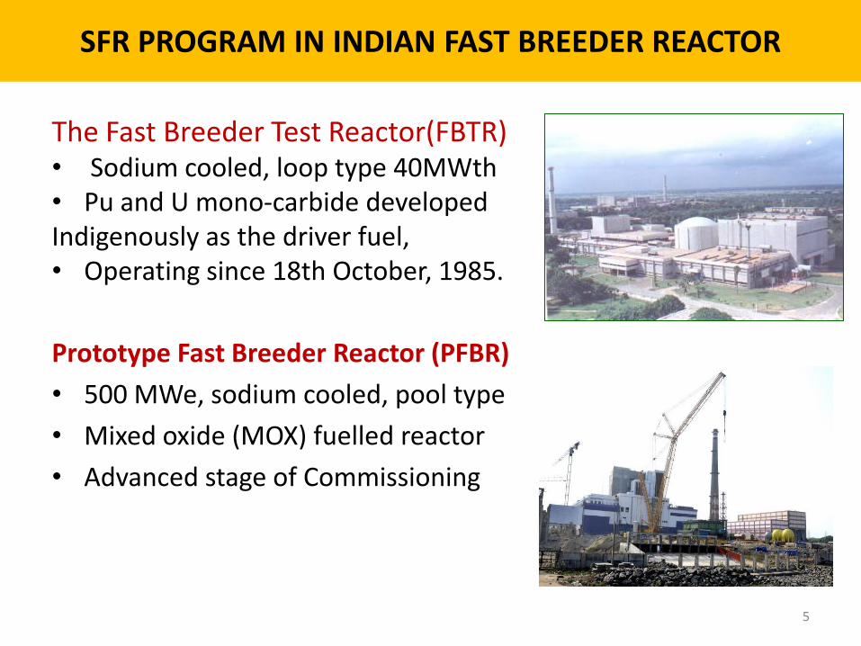
SFR PROGRAM IN INDIAN FAST BREEDER REACTOR
The Fast Breeder Test Reactor(FBTR) • Sodium cooled, loop type 40MWth • Pu and U mono-carbide developed Indigenously as the driver fuel, • Operating since 18th October, 1985.
Prototype Fast Breeder Reactor (PFBR)
• 500 MWe, sodium cooled, pool type
• Mixed oxide (MOX) fuelled reactor
• Advanced stage of Commissioning
5

FUTURE SFRs IN INDIA
FBRI &II
• The roadmap prepared for the Fast Breeder Reactor development beyond PFBR, 2x600 MWe, Fast Breeder Reactors (FBR-1&2) have been conceived.
MFTR
• In order to achieve rapid realization of nuclear power potential, early introduction of Fast Breeder Reactor (FBRs) with Metallic Fuel is essential
for India, as doubling time for metal
fuel is less.
• Towards this, a Metal Fuel Test
Reactor is being planned.
6

SFR & WASTE REDUCTION
• Breeding fuel cycles have potential to reduce actinide wastes, particularly minor actinides.
• Breeder reactors on a closed fuel cycle would use nearly all of the actinides fed into them as fuel,
• Waste generation due to leaks is negligible.
• Due to high fuel burn up in SFRs, fuel cycle time is longer due to which handling and disposal activities are reduced.
• After several hundred years in storage, the activity of the radioactive waste from a Fast Breeder Reactor would quickly drop to the low level of the long lived fission products .
• However, to obtain this benefit requires the highly efficient separation of transuranics from spent fuel.
7
• Waste Reduction at source
The reactor is designed to reduce the radioactive waste.
Reduced content of Cobalt impurity in SS
Cover gas purification- mainly Xe, Kr isotopes
Cesium trap Sub Assembly
Delay at source
8
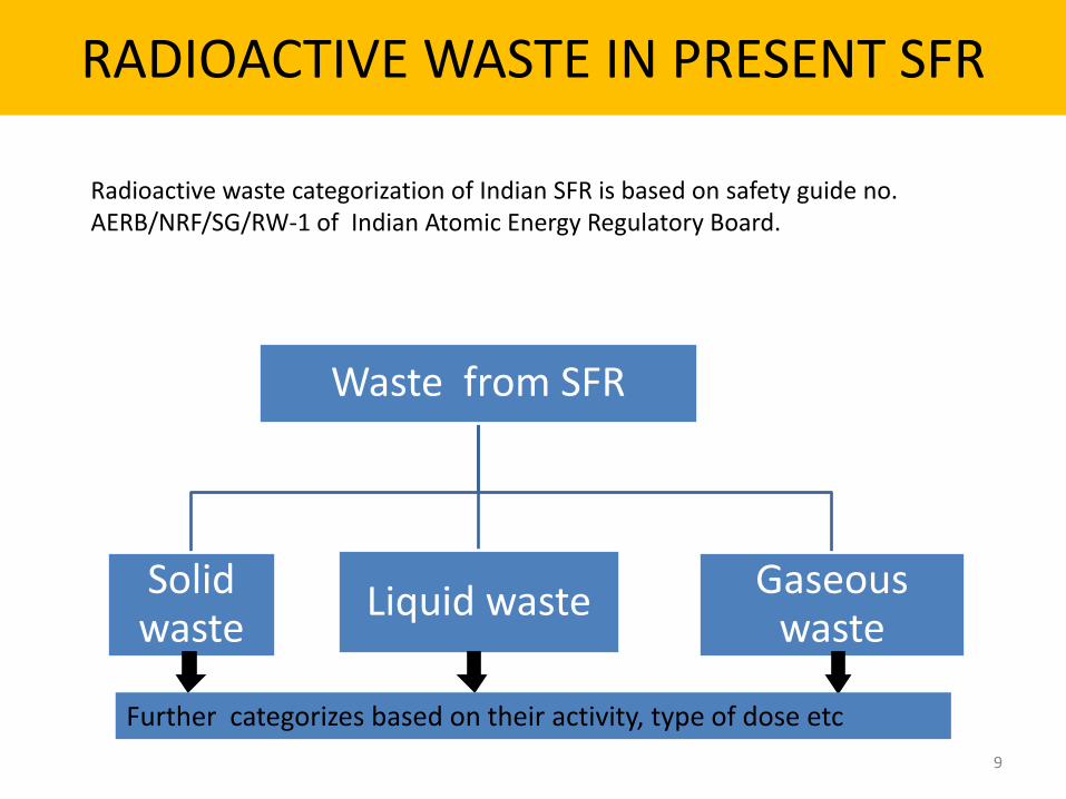
RADIOACTIVE WASTE IN PRESENT SFR
Waste from SFR
Solid waste
Liquid waste Gaseous waste
9
Radioactive waste categorization of Indian SFR is based on safety guide no. AERB/NRF/SG/RW-1 of Indian Atomic Energy Regulatory Board.
Further categorizes based on their activity, type of dose etc
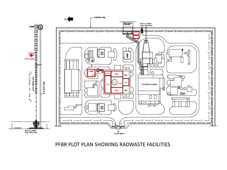
PFBR PLOT PLAN SHOWING RADWASTE FACILITIES
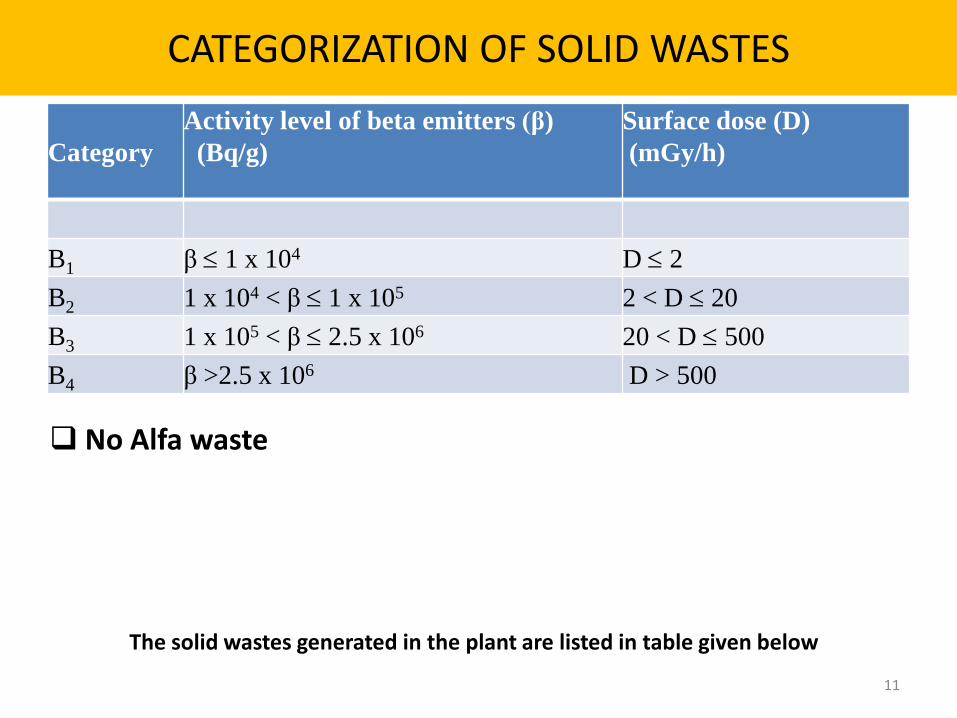
CATEGORIZATION OF SOLID WASTES
Category
Activity level of beta emitters (β)
(Bq/g)
Surface dose (D)
(mGy/h)
B1 β 1 x 10⁴ D 2
B2 1 x 10⁴ < β 1 x 10⁵ 2 < D 20
B3 1 x 10⁵ < β 2.5 x 10⁶ 20 < D 500
B4 β >2.5 x 10⁶ D > 500
11
The solid wastes generated in the plant are listed in table given below
No Alfa waste
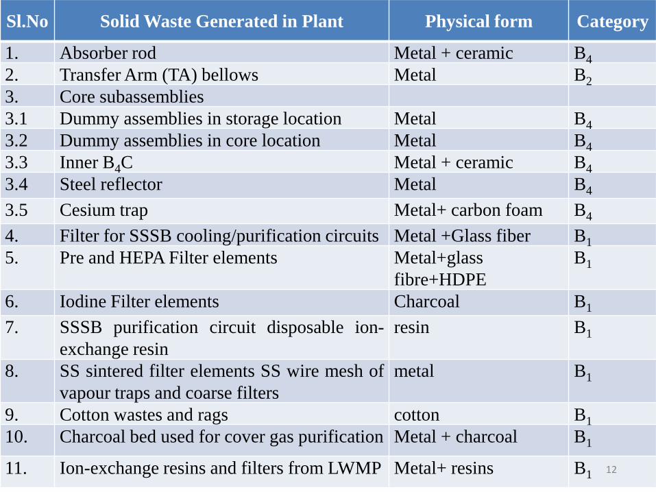
Sl.No Solid Waste Generated in Plant Physical form Category
1. Absorber rod Metal + ceramic B4
2. Transfer Arm (TA) bellows Metal B2
3. Core subassemblies
3.1 Dummy assemblies in storage location Metal B4
3.2 Dummy assemblies in core location Metal B4
3.3 Inner B4C Metal + ceramic B4
3.4 Steel reflector Metal B4
3.5 Cesium trap Metal+ carbon foam B4
4. Filter for SSSB cooling/purification circuits Metal +Glass fiber B1
5. Pre and HEPA Filter elements Metal+glass
fibre+HDPE
B1
6. Iodine Filter elements Charcoal B1
7. SSSB purification circuit disposable ion-
exchange resin
resin B1
8. SS sintered filter elements SS wire mesh of
vapour traps and coarse filters
metal B1
9. Cotton wastes and rags cotton B1
10. Charcoal bed used for cover gas purification Metal + charcoal B1
11. Ion-exchange resins and filters from LWMP Metal+ resins B1 12
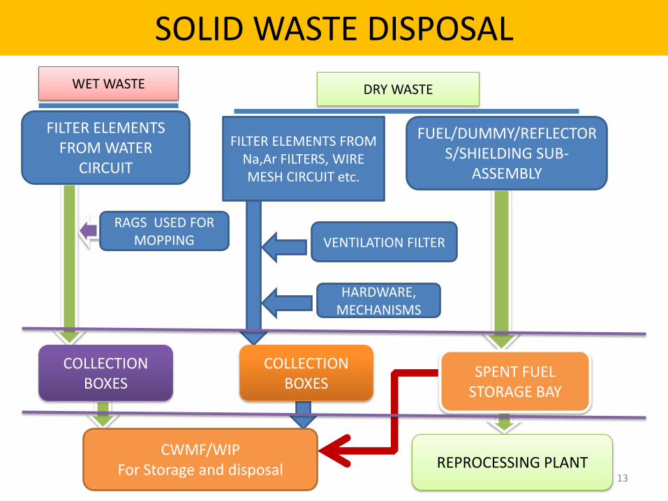
WET WASTE
RAGS USED FOR MOPPING
COLLECTION BOXES
SPENT FUEL STORAGE BAY
VENTILATION FILTER
HARDWARE, MECHANISMS
FUEL/DUMMY/REFLECTORS/SHIELDING SUB-
ASSEMBLY
FILTER ELEMENTS FROM Na,Ar FILTERS, WIRE MESH CIRCUIT etc.
COLLECTION BOXES
CWMF/WIP For Storage and disposal REPROCESSING PLANT
FILTER ELEMENTS FROM WATER
CIRCUIT
DRY WASTE
SOLID WASTE DISPOSAL
13
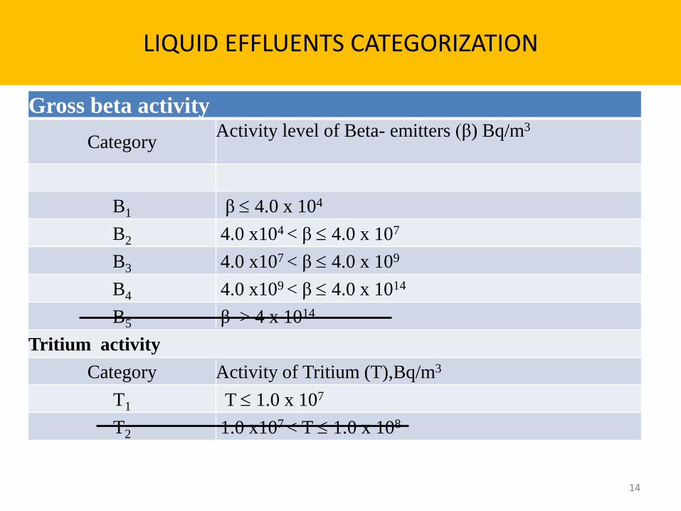
LIQUID EFFLUENTS CATEGORIZATION
Gross beta activity
Category Activity level of Beta- emitters (β) Bq/m3
B1 β 4.0 x 10⁴
B2 4.0 x10⁴ < β 4.0 x 10⁷
B3 4.0 x10⁷ < β 4.0 x 10⁹
B4 4.0 x10⁹ < β 4.0 x 10¹⁴
B5 β > 4 x 10¹⁴
Tritium activity
Category Activity of Tritium (T),Bq/m3
T1 T 1.0 x 10⁷
T2 1.0 x10⁷ < T 1.0 x 10⁸
14
SOURCES
• Potentially Active Detergent Waste
• Active low level waste, generated from drains and leakages from radioactive equipment / systems
• Higher capacity is provided for handling of exigencies like full drainage of SSSB or Biological shield Cooling System.
• Liquid effluents from Spent Sub-assembly Washing Facility (SSWF)
• Liquid effluents from Decontamination Facility
15

COLLECTION TANKS
PADW CATEGORY –
B1
RECEIVING TANK LWMP
FILTRATION
DISPOSAL TANK LWMP
COLLECTION TANKS
LEAKS & DRAINS FROM ACTIVE LIQUID
SYSTEMS, ACTIVE CHEMICAL LAB
MAX. CATEGORY B2
RECEIVING TANK LWMP
FILTRATION
DILUTION AT PFBR CWMS DISPOSAL
TO SEA
ION EXCHANGE
COLLECTION TANKS
SPENT SUB ASSEMBLY
WASHING FACILITY CATEGORY B3 & B4
COLLECTION TANKS
EFFLUENTS FROM DECONTAMINATION
FACILITY B3 &B4
CHEMICAL PRECIPITATION CEMENT FIXATION
ION EXCHANGE
POST TREATMENT TANK
TRANSPORT TO
CWMF FOR DISPOSAL IN RC TRENCH
NICB
LWMP LWTP
NICB
LWTP LWMP
FLOW DIAGRAM FOR LIQUID WASTE MANAGEMENT SYSTEM 16
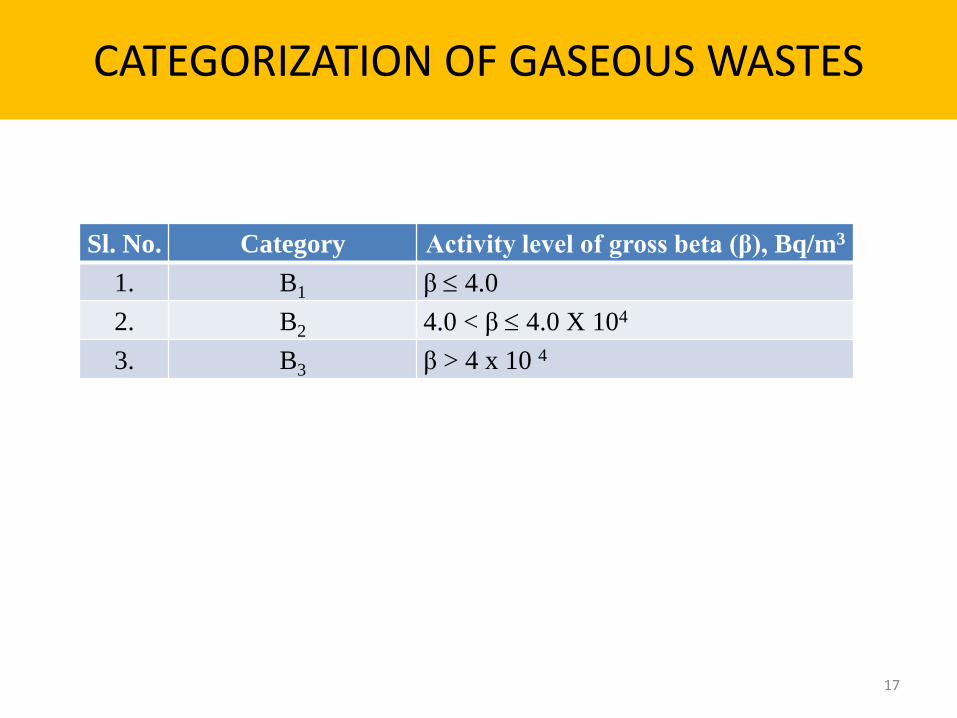
CATEGORIZATION OF GASEOUS WASTES
Sl. No. Category Activity level of gross beta (β), Bq/m3
1. B1 β 4.0
2. B2 4.0 < β 4.0 X 10⁴
3. B3 β > 4 x 10 4
17
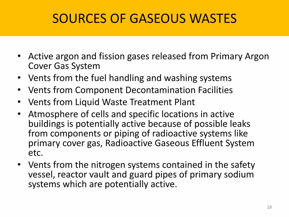
SOURCES OF GASEOUS WASTES
• Active argon and fission gases released from Primary Argon Cover Gas System
• Vents from the fuel handling and washing systems • Vents from Component Decontamination Facilities • Vents from Liquid Waste Treatment Plant • Atmosphere of cells and specific locations in active
buildings is potentially active because of possible leaks from components or piping of radioactive systems like primary cover gas, Radioactive Gaseous Effluent System etc.
• Vents from the nitrogen systems contained in the safety vessel, reactor vault and guard pipes of primary sodium systems which are potentially active.
18
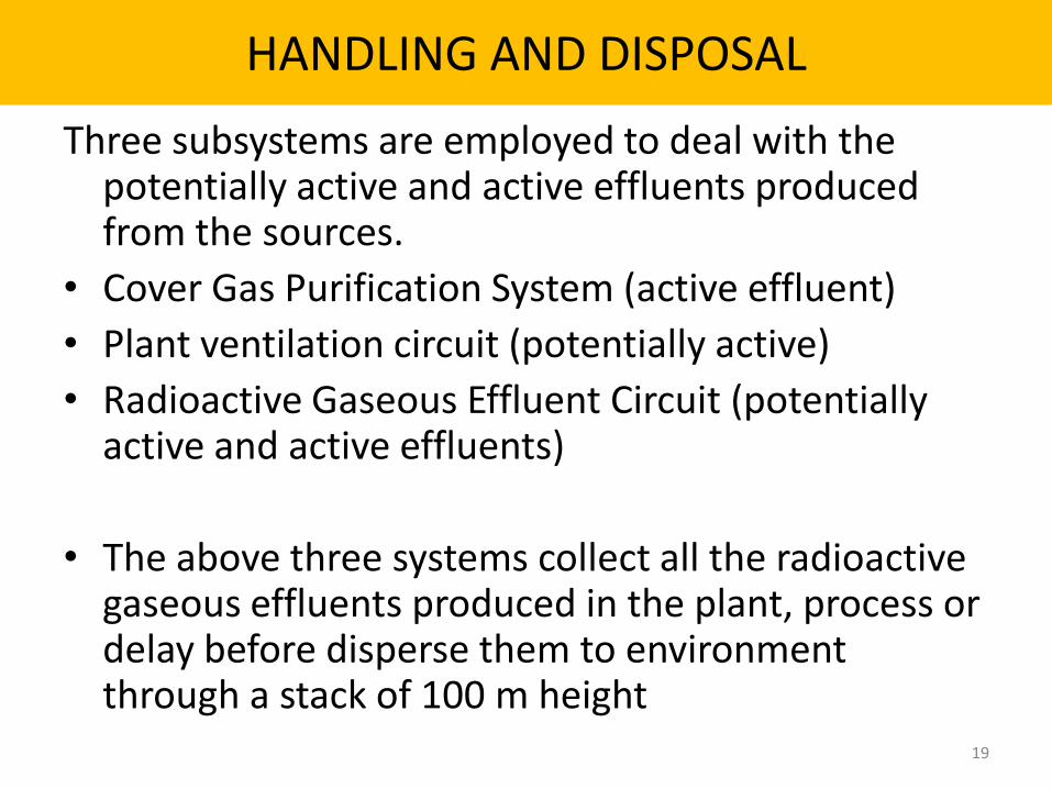
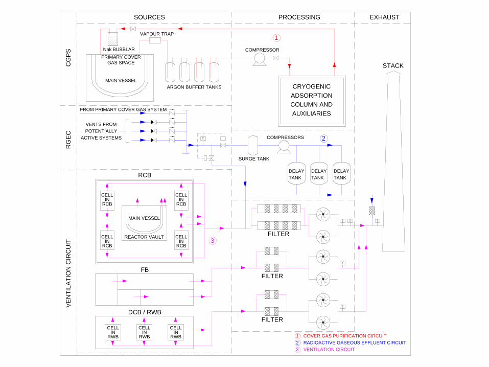
HANDLING AND DISPOSAL
Three subsystems are employed to deal with the potentially active and active effluents produced from the sources.
• Cover Gas Purification System (active effluent)
• Plant ventilation circuit (potentially active)
• Radioactive Gaseous Effluent Circuit (potentially active and active effluents)
• The above three systems collect all the radioactive gaseous effluents produced in the plant, process or delay before disperse them to environment through a stack of 100 m height
19
VAPOUR TRAP
SOURCES PROCESSING EXHAUST
CG
PS
RG
EC
VE
NT
ILA
TIO
N C
IRC
UIT
COMPRESSOR
CRYOGENIC
ADSORPTION
COLUMN AND
AUXILIARIES
DELAY
TANK
DELAY
TANK
DELAY
TANK
SURGE TANK
COMPRESSORS
Nak BUBBLAR
PRIMARY COVER
GAS SPACE
MAIN VESSEL
ARGON BUFFER TANKS
FROM PRIMARY COVER GAS SYSTEM
VENTS FROM
POTENTIALLY
ACTIVE SYSTEMS
1
2
3
RCB
FB
DCB / RWB
CELLIN
RWB
CELLIN
RWB
CELLIN
RWB
CELLIN
RCB
CELLIN
RCB
CELLIN
RCB
CELLIN
RCB
MAIN VESSEL
REACTOR VAULT
FILTER
FILTER
FILTER
1
2
3
COVER GAS PURIFICATION CIRCUIT
RADIOACTIVE GASEOUS EFFLUENT CIRCUIT
VENTILATION CIRCUIT
STACK
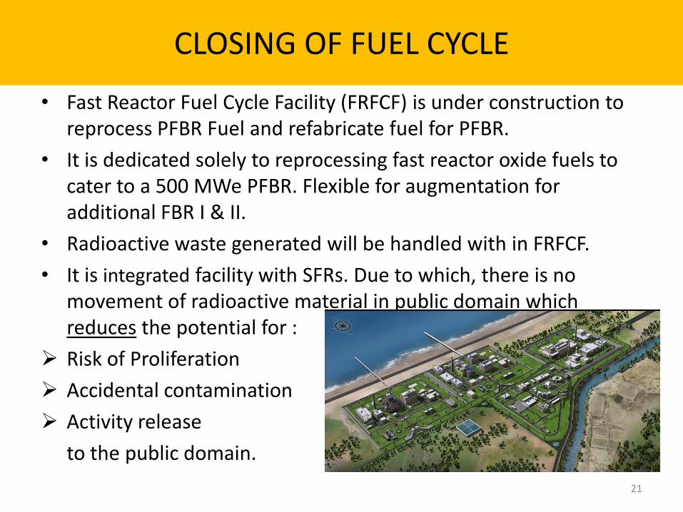
CLOSING OF FUEL CYCLE
• Fast Reactor Fuel Cycle Facility (FRFCF) is under construction to reprocess PFBR Fuel and refabricate fuel for PFBR.
• It is dedicated solely to reprocessing fast reactor oxide fuels to cater to a 500 MWe PFBR. Flexible for augmentation for additional FBR I & II.
• Radioactive waste generated will be handled with in FRFCF.
• It is integrated facility with SFRs. Due to which, there is no movement of radioactive material in public domain which reduces the potential for :
Risk of Proliferation
Accidental contamination
Activity release
to the public domain.
21

FUEL CYCLE FOR SUSTAINABLE RAD WASTE MANAGEMENT IN INDIA
• Spent fuel from PFBR,FBR I & II will be reprocessed by FRFCF.
• FRFCF is based on PUREX process for reprocessing spent fuel of PFBR due to vast experience at Thermal Reactor Fuel Reprocessing. As it is aqueous process and FBR spent fuel is high in specific activity, the waste generation is relatively large .
• A fuel cycle demonstration facility based on pyro-reprocessing is proposed for reprocessing and refabricating metal fuel irradiated in FBTR and future MFTR. In addition to other features sustainable RAD waste management will also be demonstrated in this facility.
• Towards this, a program for using FBTR as a test bed for developing essential data related to metal fuel is put in place.
22
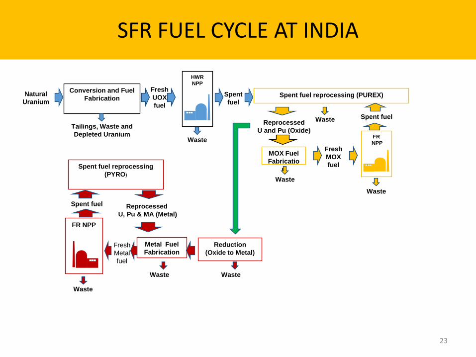
SFR FUEL CYCLE AT INDIA
23
Natural
Uranium
Conversion and Fuel
Fabrication
Tailings, Waste and
Depleted Uranium
HWR
NPP
Fresh
UOX
fuel
Waste
Spent
fuel Spent fuel reprocessing (PUREX)
Reprocessed
U and Pu (Oxide)
Waste
Reprocessed
U, Pu & MA (Metal)
Reduction
(Oxide to Metal)
Metal Fuel
Fabrication
Waste
FR NPP
Fresh
Metal
fuel
Spent fuel
Waste
Spent fuel reprocessing
(PYRO)
Waste
MOX Fuel
Fabricatio
n
Fresh
MOX
fuel
Waste
FR
NPP
Waste
Spent fuel
• India is following a three stage program comprising PHWR, FBR and Thorium fuelled reactors to harness the domestic nuclear resources for a large ambitious nuclear based power program
• India has adopted closed fuel cycle program which incorporates inherently the principles of maximization of nuclear resources utilization and minimization of radioactive waste
• Fast neutron spectrum based Sodium Cooled Fast Reactors are ideal and possess the required matching characteristics for faster reduction of radio toxicity required for a large power program of India.
• Aqueous reprocessing technology has been mastered, deployed and has been demonstrated for the ceramic fuels.
• For the future metal fuels, R&D is in progress in the domain of pyrochemical reprocessing process along with the technologies required for waste management and waste reduction.
24
SUMMARY

PROPOSAL FOR INPRO METHODOLOGY
1. The following para may be added at page 51 of INPRO methodology with above Figure:
• Fig. II.8 shows an example of a NES consisting of fast and thermal reactors and recycling of MOX and metal fuel. MOX based fast reactors generate sufficient fissile inventory to feed Metal fuel based fast reactors initially. As it is mentioned above PUREX process is being used as a reprocessing technique and research is going on other methods for effective separation of actinides. Research is also under progress in various countries for development of a non aqueous reprocessing method, based on molten salt electrorefining, called Pyroprocess. In this process minor actinides remain with Pu and therefore no additional minor actinides recycling method is required. Minor actinides form part of the fast reactor fuel and get burned. Another advantage of this process from waste management point of view is that no significant high level liquid wastes will be generated. This system does not required U enrichment facility and inherently achieves MA burning. The breeding capability of metal fuel FR can provide faster growth of nuclear energy, thus meeting the future energy needs. This NES can prove to be among the most sustainable systems.
• Breeder reactors on a closed fuel cycle would use nearly all of the actinides fed into them as fuel, It enables a dramatic improvement by more than a factor of 100 in the utilization of uranium resources. [74].
25
2. Based on indicators (IN1.1 to IN 3.3) mentioned in INPRO methodology a quantitative scale may be generated to rate any facility. For example; based on Mass, volume, activity, half life of generated waste, disposal methodology, dose during disposal, burn up of fuel, quantity of transuranic in waste etc normalized to 1GW.a of electricity produced, different grading for sustainable waste management can be given for the ease of assessor . The quantification for the sustainability of a given system can be carried out on a scale of say, 1 to 10 based on a reference NES which has indicators satisfying criteria for sustainability.
26

ACKNOWLEDGEMENTS
27

THANK YOU

Operating Capacity : 5780 Mwe • The operating nuclear power units are: • Tarapur Atomic Power Station Units-1&2 (2x160 MW BWRs),
Tarapur Atomic Power Station Units-3&4 (2x540 MW PHWRs), Rajasthan Atomic Power Station Units 1to 6 (100 MW, 200 MW and 4x220 MW PHWRs), Madras Atomic Power Station Units-1&2 (2x220 MW PHWRs), Narora Atomic Power Station Units-1&2 (2x220 MW PHWRs), Kakrapar Atomic Station Units-1&2 (2x220 MW PHWRs), Kaiga Generating Station Unit-1 to 4 (4x220 MW PHWRs) and Kudankulam Nuclear Power Project Unit-1 (1x1000 MW VVER) *
• In addition, NPCIL also has a 10 MW Wind Power Plant at Kudankulam site.
• * Unit -1 of KKNPP has started commercial operation on December 31, 2014
The units under construction/commissioning are: • Kudankulam Nuclear Power Project Unit-2 (1x1000 MW VVER)
Kakrapar Atomic Power Project Unit-3&4 (2x700 MW PHWRs) Rajasthan Atomic Power Project Units-7&8 (2x700 MW PHWRs)
29