fairey swordflsh - bigplanes · instruction manual first-time builders should seek advice from...
TRANSCRIPT

SAFETY PRECAUTIONS
INSTRUCTION MANUAL
First-time builders should seek advice from people having building experience.If misused or abused,it can cause serious bodily injury and damage to property.Fly only in open areas and preferably at a dedicated R/C flying site.We suggest having a qualified instructor carefully inspect your airplane before its first flight.Please carefully read and follow all instructions included with this airplane,your radio control system and any other components purchased separately.
(The people under 18 years old is forbidden from flying this model)This R/C airplane is not a toy!
FAIREY SWORDFLSH
Specification:Length :1700 mm(67") Wing Span :2160 mm(85.4")Wing Area :129/sq. dm 13.9/sq.ftWing Loading :69.8g/sq. dm 22.8oz/sq. ftFlying Weight :9000g(19.8 lbs)Radio :6ch & 7servosEngine(a pair) :180 4-cycle

: 4-cycle .180
18"x10Spinner nut
6
(with 7 servos),6
6
6 channel radio for aiplane is highly recommended for this model.
WarningRemove the covering with proper pressure to cut through only the covering itself.Otherwise,cutting down into the balsa structure may weaken the model part and cause accident.
The pre-covered film on ARF kits may wrinkle due to variations of temperature.Smooth out as explained right.
Apply
Pre-cover the covering with clean cloth!Start at low setting. Increase the setting ifnecessary.If it is too high,you may damagethe film.
Iow settingwith cover(cloth)
Top view
Side View
25mm
25mm
RUDDER
AILERON20mm
20mm
Side View
Adjustment.
Centre of Gravity.
AILERON
AILERON
130mm
Adjustment. 90
91
89
17

5mm
20mm 170mm
20mm
Drill holes to relevant position on the fuselage and epoxy the dummy bomb in it steadily.
Epoxy the small fairings to appropriate position on the fuselage.
Epoxy the PVC to the ply and glue it to the fuselageas illustration.
Top view
Position forright diagram.
ELEVATOR
Side View
20mm20mm
5mm
4mm
Epoxy the wire to the relevant holes as illustration.
113mm15mm
Trim the dummy radiator careful along the shaded line and epoxy it to relevant position on the fuselage.
1 Metal wire
Adjustment.
84
83
85
86
87
88
16
Accessory list for the coming installation steps.
1mm
Aileron
Trailing edge
Make sure they are inthe right position whileinstalling.
Make sure hinges are mounted in the same line.
6Pin hinge(24x24mm)
8
6
22
2
4
2
2
2
2
Clevis
Rod (2x300mm) Retainer
TP Screw (2.3x12mm)
Wooden Block(20x20x8mm)Servo tray(68.5x56.5x2mm)
Pin hinge(24x24mm)
Screw (3x40mm)
Washer(3x15mm)
2Washer(3x15mm)
Lock Nut (3mm )
Clevis
Retainer Rod (2x300mm)
Screw (2x10mm)
Securely glue together. If coming off during flights, you 'lllose control of your airplane which leads to accidents!
Install the nylon control horn and connect the linkage.
Install the servo as the illustration belowApply instant type CA glue to the aileron of top wing and pin hinge..
Keep 1mm width space between aileron and trailing edge.
Assemble the aileron to main wing with instanttype CA glue.
1
2
3
4
5
1
Accessory list for the coming installation steps.

TP Screw (2.3x12mm)
3mm
1.5mm
Rod (2x300mm)
Clevis
Washer(3x15mm)
Washer
Lock Nut (3mm )
Screw (3x40mm)
8
6
22
2
4
2
2
2
2
Clevis
Rod (2x300mm) Retainer
TP Screw (2.3x12mm)
Wooden Block(20x20x8mm)Servo tray(68.5x56.5x2mm)
Pin hinge(24x24mm)
Screw (3x40mm)
Washer(3x15mm)
2Washer(3x15mm)
Lock Nut (3mm )
Make sure hinges are mounted in the same line.
6Pin hinge(24x24mm)
Securely glue together. If coming off during flights, you 'lllose control of your airplane which leads to accidents!
1mm
Aileron
Trailing edge
Make sure they are inthe right position whileinstalling.
Keep about 1mm width space between aileron and trailing edge.
Install the servo as the illustration below
Secure the servo.Install the nylon control horn andconnect the linkage.
Apply instant type CA glue to the aileron of bottom wing and pin hinge.
Assemble the aileron to main wing with instanttype CA glue.
7
6 8
9
10
2
Accessory list for the coming installation steps.
2Plastic tube (5x50mm)
TP Screw (2.3x8mm)
12TP Screw (2.3x8mm)
Ply (15x15x3mm) 12
TP Screw (3x20mm)
TP Screw (3x20mm)
4
1.5mm
Epoxy the dummy engine to appropriate position in the cowl.
5mm Marked dotMarked dot
Washer (3x6mm)
Washer (3x6mm)
4
18mm
104mm
1x3
Epoxy the cowl frame to appropriate position in the cowl.
Epoxy the cowl frame to appropriate position in the cowl.
Cut the surplus portion off the dummy engine carefully.
Drill holes to appropriate position in the dummy bomb and epoxy the wood dowel in them.
Covering the landing gear section which on the fuselage with PVC parts.
77 80
78
79
81
80
15
82

1.5mm
TP Screw (2.3x12mm)
TP Screw (2.3x12mm)
4
2Stabilizer strut
8Screw (3x10mm)
Screw (3x10mm)
Assemble the stabilizer strut.
TP Screw (2.3x12mm) 4
TP Screw (2.3x8mm) 12
TP Screw (3x20mm) 4
1PVC
1PVC 3PVC
1PVC1PVC
1Dummy engine
1Cowl mount
1Cowl mount
12Plastic tube (5x50mm)
Ply (15x15x3mm) 12Ply (9mm) 3
Metal wire
Lock Nut (3mm )
Washer(3x6mm)
Stee l w i re
Lock Nut (3mm )
Washer(3x6mm)
Stee l w i re
16
1616Washer(3x6mm)
Lock Nut (3mm )
2Steel wire (0.5x3000mm)
Metal clevises
Connect the steel wire to the wing strut and fix them with lock nut.
Notice the alignment of the steel wire when assemble it.
Notice the alignment of the steel wire when assemble it.
36mm
13mm
Washer (3x6mm) 4
Assemble the cowl mount to the head of fuselage.
72
74
71
73
75
76
14
Accessory list for the coming installation steps.
Accessory list for the coming installation steps.
TP Screw (2.3x12mm)
Clevis
Retainer Rod (2x300mm)
Screw (2x10mm)
6mm
6mm
10Wood dowel (6x50mm)
1Rib template (2mm ply)
1Rib template (2mm ply)
4Wood dowel (6x50mm)
1Rib template (2mm ply)
Rib template (2mm ply)
Rib template (2mm ply)
Fibre wing joiner 2
Fibre wing joiner2
1Main wing joiner (20x980mm)
22Blind Nut (6mm)
Screw(6x50mm)83x20mm TP Screw
Landing gear straps 4
16
16
Screw (3x20mm)
Nut (3mm )34Washer (3x6mm)
2Screw (3x16mm)
1Screw (4x40mm)
16TP Screw (2.3x8mm)
A
B
1
1
1 Aluminum block
Matel wing struts
Matel wing strutsMatel wing strutsMatel wing strutsMatel wing strutsMatel wing struts
1
2222
Wood wing struts(3mm)
Install the nylon control horn and connect the linkage. According to the rib template drill holes to the top outer wing and epoxy wood dowel in them.
Secure the servo.Install the nylon control horn and connect the linkage.
3mm1.5mm
Rod (2x300mm)
Clevis
Washer(3x15mm)
Washer
Lock Nut (3mm )
Screw (3x40mm)
According to the rib template drill holes to the top mid-wing.
Assemble the top wings hardly together by the wing joiner.
12
11
15
3
14
13
Accessory list for the coming installation steps.

6mm
4Wood dowel (6x50mm)
Rib template (2mm ply)
Rib template (2mm ply)
6mm
1Rib template (2mm ply)
1Main wing joiner (20x980mm)
108mm
108mm
6mm
6mm
Screw(3x16mm)
2Screw (3x16mm)
Washer (3x6mm)
Washer (3x6mm)2
2Wood dowel (6x50mm)
Wood dowel (6x50mm)
Drill holes to relevant position in the fuselage.
According to the rib template drill holes to the bottom outer wing and epoxy wood dowel in them.
According to the rib template drill holes to the bottom mid-wing.
Assemble the bottom wings hardly together by the main wing joiner.
Drill holes to appropriate position in the front of the bottom mid-wing.
Fix the wings steadily with screw.
17
18
19
20
21
4
16
2Lower wing strut
8Screw (3x10mm)
Fix the oleo strut to the main landing gear and the metal plate as plan.
22Screw (4x16mm)
Screw (4x16mm)
Washer(4x12mm)
Washer(4x12mm)
2
TP Screw(3x10mm)
TP Screw(3x10mm)
8Washer (3x6mm)
Metal plate8
Fix the metal plate to the appropriate position steadily on the bottom of the lower wing.
3mm Nylon Nut
Fix the oleo strut to the main landing gear and the metal plate as plan.
2
22Screw (3x20mm)
Washer(3x6mm)
Oleo strut2Nut (3mm )
Screw (3x20mm)
Washer(3x6mm)
2PVC
2Screw (3x10mm)
1.5mm
Marked dot
Fix one side of the lower wing strut to appropriate position on the lower centre wing root.
Fix another side of the lower wing strut to the fuselage and glue the PVC parts to it as illustration.
Fix another side of the lower wing strut to the fuselage and glue the PVC parts to it as illustration.
8mm
67
68
69
70
13
66
65

1Main landing gear
Washer (5x16mm) 82Screw (5x45mm)
2Screw (4x16mm)
2Wheel (115 mm)
Wheel (115 mm)
2Nut (5mm )
2
5mm Nut
5x45mm Screw
5mm Nylon Nut
5x16 mm Washer
5x16mm Washer
4.2mmBlind Nut
22
TP Screw (3x20mm)
18Screw (3x16mm)TP Screw(3x10mm)8
2Steel wire (0.5x3000mm)
16
1826Washer(3x6mm)
Lock Nut (3mm )
2Nut (3mm )
2Main landing gear
2PVC4Main landing gear Lock Nut (5mm )
Metal clevises
Metal plateOleo strut
12Screw (3x20mm)
12Blind Nut (3mm)
12Screw (3x20mm)
12Blind Nut (3mm) 2Washer(4x12mm)
2Screw (3x20mm)
Install the servo of switch.
The sketch map when the servos install completion.
switch servo
Throttle servo
Rudder servo
Elevator servo
163mm146mm
Assemble the receiver and the battery to appropriatepositon in the fuselage.
Assemble the main landing gear to fuselage with screw.
Assemble the wheel to the main landing gear as illustration.
60
63
64
12
61
62
Accessory list for the coming installation steps.
3x20mm TP Screw
83x20mm TP Screw
Landing gear straps 4
AB
A
B
Set screw(3mm) 4
1
1
1 Aluminum block
Aluminum block
A’A
A=A’
The front view when the wings strut assembled completely. The sketch map when the wing strut assembly completion.
Using the wood wing struts to hold the wings first in appropriate position.
6.2mm
Blind Nut
22Blind Nut (6mm)
Screw(6x50mm)
Screw(6x50mm)
Set blind nut to appropriate position in the fuselage and assemble the bottom wings to fuselage with screw as illustration.
1
234
223mm 242mm 249mm 247mm
Matel wing struts
Matel wing struts
Assemble the top mid-wing struts to the aluminum block until right position and fix them with set screw.
Fix the top mid wing struts to the fuselage with gearplates as illustration.
set screw
Wood wing struts(3mm)
Wing leading edge
Wing leading edge
12
1Wood wing struts(3mm)
23
24
25
26
27
5
22

Screw
Spring Washer
Nut
8
8
Screw (3x20mm)
Nut (3mm )16 Aluminum Washer (3x6mm)
Screw
Spring Washer
Nut
1Screw (4x40mm)
Screw (4x40mm)
Assemble the aluminum block to appropriate position on bottom of the top wing with screw.
Assemble the metal wing struts to appropriate positionin the wing as illustration.
Fix the top and bottom wing strut with screws.
The surplus parts of the screws arefor the steel wires in the final.
The sketch map whe the stabilizer and rudder assemblecompletion.
6Pin hinge(24x24mm)
3Pin hinge(2.5x48mm)1U-style wire (25x140mm)
Washer (4x12mm) 2
2Screw (4x90mm)
TP Screw (2.3x8mm)
16TP Screw (2.3x8mm)
Assemble the fiber cover to fuselage with the top screw as plan.
12
12
34
3mm
8
8
Screw (3x20mm)
Nut (3mm )16 Aluminum Washer (3x6mm)
Screw
Spring Washer
Nut
4mm
Marked dot
Put the top wing on the appropriate position of fuselage.
Marked dot
Screw
Spring Washer
Nut
A
A=A’
A’
28
29
3230
6
Accessory list for the coming installation steps.
31
Accessory list for the coming installation steps.
Set Screw (3x4mm)
Set Screw (2mm)
Rod (2x350mm)
Set Screw (2mm)
Washer (2mm)
Linkage Stopper 2
Set Screw (3x4mm)
2
2
2
Assemble the accelerator push rod to the engine.
1Retainer
242
ClevisCopper joiner
Aluminum tube(3x6mm)
33
Screw (2x10mm) Nut (2mm )
3Washer(2x5mm)
Assembly of the elevator servo.
Retainer
Rod (2X300mm)
11
Ring
1Swi tchClevis 1
2
22
ClevisCopper joiner
Aluminum tube(3x6mm)
22
Screw (2x10mm) Nut (2mm )
2Washer(2x5mm)
Stee l w i re
Copper joinerAluminum tubeLock Nut (2mm )
Screw (2x10mm)
Ball joint
Washer(2x5mm)
Assembly of the rudder servo.
The sketch map of the the push rod assemble completion
Washer (4x8mm)
Washer (4x8mm)
Washer (4x8mm)
Screw (4x35mm)
Screw (4x45mm)
Nut (4mm)Spring Washer (4mm)
4mm
Assemble the engine as below.
6.2mm
Blind Nut
Blind Nut (4mm) 4
Down action the center line,drilling holes and set blind nut to the appropriate symmetrical position for assembling engine mount.55
56
55
57
58
11
59
Polish the surface flat.
Accessory list for the coming installation steps.

4Blind Nut (4mm)
1Engine mount (68x105mm)
Linkage Stopper44
12
4
Washer(4x8mm)
Screw (4x35mm)
Spring Washer (4mm) Nut (4mm)
2
4Screw (4x45mm)
2
Plastic tube (2x400mm)
Fuel tank (550cc) 1
In case of 2-cycle & 4-cycle engine.
TP Screw (2.3x8mm)
8TP Screw (2.3x8mm)
Ply (15x15x3mm) 8
Epoxy ply to appropriate position in the fuselage and assemble the tail gear cover with screw.
178mm
18mm
25mm
Fire plate template (2mm ply)
Fire plate template (2mm ply)
11Fire plate template (2mm ply)
4mm
Drill holes to appropriate position in the fire plate template according to thr engine mount.
According to the fire plate template mark on the fire plate.
Marked dot Marked dot
1 ply(92X98X18mm)
ply(92X98X18mm)
1 ply(92X98X18mm)
The front view of the engine installation finished.
The side sketch map of the engine installation finished.
51
52
53
54
10
50
Accessory list for the coming installation steps.
Drill holes to the vertical fin and epoxy the rudder to the fuselage as below.
Make sure hinges are mounted in the same line. 3Pin hinge(2.5x48mm)
2.5mm
Securely glue together. If coming off during flights, you 'lllose control of your airplane which leads to accidents!
U-style wire (25x140mm)
111mm 67mm 32mm
Make sure hinges are mounted in the same line.
6Pin hinge(24x24mm)
1mm
Elevator
Tailing edge
Make sure they are inthe right position whileinstalling.
keep about 1mm width space between stabilizer and elevator.
3mm
Screw (4x90mm)
Spring Washer
Fix the vertical fin to fuselage with screw from the bottom of the tail fuselage.
Blind Nut (4mm)Washer (4x12mm)
2
2Screw (4x90mm)
3mm
Marked dot
Put the stabilizer to appropriate position on the fuselage and drill holes throught the stabilizer and tail fuselage.
Trim a slot and drill a hole to appropriate position in the elevator,apply instand type CA clue to the stabilizer and pin hinges.
Epoxy the "U" style metal wire to the holes in the elevator first,then epoxy the elevator to the stabilizer as plan.34
35
36
37
38
7
33
1mm
Rudder
Tailing edge
Cut away the rubber tube whenthe epoxy glue dried.
Make sure they are inthe right position whileinstalling.
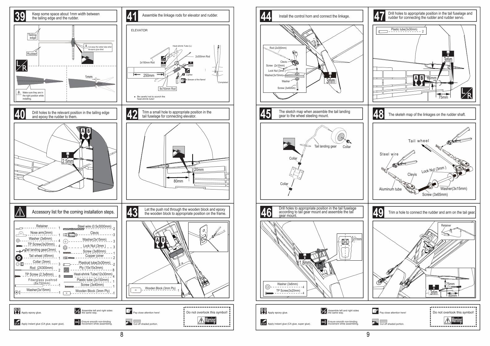
Keep some space about 1mm width between the tailing edge and the rudder.
2.5mm
Drill holes to the relevant position in the tailing edge and epoxy the rudder to them.
2Plastical tube(3x30mm)
1Nose arm(3mm)
Collar (3mm) 311Tail landing gear(3mm)
Tail wheel (45mm)
1Retainer
Rod (2X300mm) 2
TP Screw(3x20mm)Washer (3x6mm)
44
2Steel wire (0.5x3000mm)
3
33
Clevis
Washer(3x15mm)Lock Nut (3mm )
1Screw (3x80mm)
2Copper joiner
8TP Screw (2.3x8mm)
Ply (15x15x3mm) 8
2x150mm Rod
2x300mm Rod
8x750mm Rod
250mm
Assemble the linkage rods for elevator and rudder.
F iberg lass pushrod (8x750mm) 1
Heat-shrink Tube(12x30mm)41Plastic tube (2x150mm)
80mm
20mm
1Screw (3x40mm)
1Washer(3x15mm)
1 Wooden Block (3mm Ply)
Let the push rod through the wooden block and epoxythe wooden block to appropriate position on the frame.
1 Wooden Block (3mm Ply)
Trim a small hole to appropriate position in the tail fuselage for connecting elevator.40
41
8
42
43Accessory list for the coming installation steps.
39
80mm
75mm
3mm
The sketeh map of the linkages on the rudder shaft.
Ta i l whee l
Washer(3x15mm)Screw (3x65mm)
Lock Nut (3mm )Clevis
Aluminum tube
Stee l w i re
Drill holes to appropriate position in the tail fuselage andrudder for connecting the rudder and rudder servo.
3mm
60mm
75mm
2Plastic tube(3x30mm)
Retainer
1.8mm
TP Screw(3x20mm)
Washer (3x6mm)
4
4
27mm
Trim a hole to connect the rudder and arm on the tail gear.
Collar Tail landing gear
Collar
Collar
The sketch map when assemble the tail landing gear to the wheel steeling mount.
Clevis
Washer(3x15mm)
Washer
Lock Nut (3mm )
Screw (3x40mm)
Screw (2x10mm)
Rod (2x300mm)
3mm
Install the control horn and connect the linkage.
Drill holes to appropriate position in the tail fuselage according to tail gear mount and assemble the tail gear mount.
44
46
45
47
9
48
49