failure modes and effects analysis (fmea) of welded ......dec 17, 2013 · report. the third covers...
TRANSCRIPT

2013 TECHNICAL REPORT
Failure Modes and Effects Analysis (FMEA) of Welded Stainless Steel Canisters for Dry Cask Storage Systems


EPRI Project Manager S. Chu
All or a portion of the requirements of the EPRI Nuclear Quality Assurance Program apply to this product.
ELECTRIC POWER RESEARCH INSTITUTE 3420 Hillview Avenue, Palo Alto, California 94304-1338 ▪ PO Box 10412, Palo Alto, California 94303-0813 ▪ USA
800.313.3774 ▪ 650.855.2121 ▪ [email protected] ▪ www.epri.com
Failure Modes and Effects Analysis (FMEA) of Welded Stainless Steel Canisters for Dry Cask Storage Systems
3002000815
Final Report, December 2013

DISCLAIMER OF WARRANTIES AND LIMITATION OF LIABILITIES
THIS DOCUMENT WAS PREPARED BY THE ORGANIZATION(S) NAMED BELOW AS AN ACCOUNT OF WORK SPONSORED OR COSPONSORED BY THE ELECTRIC POWER RESEARCH INSTITUTE, INC. (EPRI). NEITHER EPRI, ANY MEMBER OF EPRI, ANY COSPONSOR, THE ORGANIZATION(S) BELOW, NOR ANY PERSON ACTING ON BEHALF OF ANY OF THEM:
(A) MAKES ANY WARRANTY OR REPRESENTATION WHATSOEVER, EXPRESS OR IMPLIED, (I) WITH RESPECT TO THE USE OF ANY INFORMATION, APPARATUS, METHOD, PROCESS, OR SIMILAR ITEM DISCLOSED IN THIS DOCUMENT, INCLUDING MERCHANTABILITY AND FITNESS FOR A PARTICULAR PURPOSE, OR (II) THAT SUCH USE DOES NOT INFRINGE ON OR INTERFERE WITH PRIVATELY OWNED RIGHTS, INCLUDING ANY PARTY'S INTELLECTUAL PROPERTY, OR (III) THAT THIS DOCUMENT IS SUITABLE TO ANY PARTICULAR USER'S CIRCUMSTANCE; OR
(B) ASSUMES RESPONSIBILITY FOR ANY DAMAGES OR OTHER LIABILITY WHATSOEVER (INCLUDING ANY CONSEQUENTIAL DAMAGES, EVEN IF EPRI OR ANY EPRI REPRESENTATIVE HAS BEEN ADVISED OF THE POSSIBILITY OF SUCH DAMAGES) RESULTING FROM YOUR SELECTION OR USE OF THIS DOCUMENT OR ANY INFORMATION, APPARATUS, METHOD, PROCESS, OR SIMILAR ITEM DISCLOSED IN THIS DOCUMENT.
REFERENCE HEREIN TO ANY SPECIFIC COMMERCIAL PRODUCT, PROCESS, OR SERVICE BY ITS TRADE NAME, TRADEMARK, MANUFACTURER, OR OTHERWISE, DOES NOT NECESSARILY CONSTITUTE OR IMPLY ITS ENDORSEMENT, RECOMMENDATION, OR FAVORING BY EPRI.
THE FOLLOWING ORGANIZATION, UNDER CONTRACT TO EPRI, PREPARED THIS REPORT:
Dominion Engineering, Inc.
THE TECHNICAL CONTENTS OF THIS PRODUCT WERE NOT PREPARED IN ACCORDANCE WITH THE EPRI QUALITY PROGRAM MANUAL THAT FULFILLS THE REQUIREMENTS OF 10 CFR 50, APPENDIX B. THIS PRODUCT IS NOT SUBJECT TO THE REQUIREMENTS OF 10 CFR PART 21.
NOTE
For further information about EPRI, call the EPRI Customer Assistance Center at 800.313.3774 or e-mail [email protected].
Electric Power Research Institute, EPRI, and TOGETHER…SHAPING THE FUTURE OF ELECTRICITY are registered service marks of the Electric Power Research Institute, Inc.
Copyright © 2013 Electric Power Research Institute, Inc. All rights reserved.

This publication is a corporate document that should be cited in literature in the following manner:
Failure Modes and Effects Analysis (FMEA) of Welded Stainless Steel Canisters for Dry Cask Storage Systems. EPRI, Palo Alto, CA: 2013. 3002000815.
iii
ACKNOWLEDGMENTS
The following organization, under contract to the Electric Power Research Institute (EPRI), prepared this report:
Dominion Engineering, Inc. 12100 Sunrise Valley Drive, Suite 220 Reston, VA 20191
Principal Investigators K. Fuhr J. Gorman J. Broussard G. White
This report describes research sponsored by EPRI.


v
PRODUCT DESCRIPTION
Due to the delayed opening of a final geological repository for spent nuclear fuel, the lifespan of dry cask storage systems may be increased to 120 years or longer. To ensure safety over this extended period of interim storage, degradation mechanisms that have the potential to cause penetration of the canister confinement boundary must be evaluated and understood. To address this issue, the Electric Power Research Institute (EPRI) performed a failure modes and effects analysis (FMEA) to identify credible degradation mechanisms and their consequences during on-site storage prior to eventual transport to a final repository or reprocessing facility.
Background The majority of nuclear plants have constructed an independent spent fuel storage installation (ISFSI) to relieve crowding in the spent fuel pool using dry cask storage systems (DCSSs). As a result of concerns that corrosion of the DCSS’s inner stainless steel canisters may occur at some sites over an extended life of 120 years or longer, the Electric Power Research Institute (EPRI) is developing an Aging Management Plan. The Plan includes susceptibility criteria to identify conditions that may lead to a loss of the confinement function of stored DCSSs.
Objectives • To identify the aging-related degradation mechanisms that may be active during the extended
lifetime of stainless steel canisters used as the confinement boundary of some dry cask spent fuel storage systems.
• To determine the potential consequences of the associated failure modes.
Approach This FMEA is comprised of six sections. The first and second are an introduction to the report and background information on the different DCSS designs considered within the scope of this report. The third covers the process, criteria, and terminology used in this FMEA. The fourth discusses the technical details of the degradation mechanisms, canister failure modes, and the potential consequences of canister degradation. The fifth and sixth sections cover the implications of the FMEA and the conclusions of the report, respectively. An appendix includes calculations that consider the residual stresses resulting from canister shell rolling and from welding. The report also includes an appendix that examines a consideration of transportation, after the extended storage life, as a source of cyclical and accident stresses and an appendix that examines issues specific to fuel assemblies with stainless steel cladding.
Results The credible degradation mechanisms identified by this FMEA are (in order of likelihood) chloride-induced stress corrosion cracking (CISCC), pitting, crevice corrosion, microbiologically induced corrosion, and intergranular attack. Of the degradation mechanisms, CISCC is concluded to be of greatest potential concern for causing penetration of the confinement boundary. The most likely mode of canister confinement failure is the through-wall growth and

vi
penetration of a crack. Other less likely modes include a gross corrosion defect and the rupture of a part-depth or through-wall crack. The consequences of a loss of the canister confinement boundary are considered principally for the integrity of the fuel cladding and for the potential for release of radioactive material. The most susceptible locations are expected to be the cooler regions of the shell near welds at ISFSIs proximal to marine environments with breaking waves.
Applications, Value, and Use The FMEA categorizes the degradation mechanisms in terms of detectability, likelihood, and severity of consequence, permitting resource focus on the most important mechanisms. Subsequent to this FMEA, EPRI is developing an Industry Susceptibility Assessment Criteria report to address the major degradation concerns identified and prioritized by this FMEA. That report will reflect the results of a flaw growth and flaw tolerance assessment, and the results of a literature review on CISCC and relevant degradation mechanisms. These reports will be developed into an Aging Management Plan to support long-term management of this issue.
Keywords Dry cask storage system (DCSS) Spent nuclear fuel storage Chloride-induced stress corrosion cracking (CISCC) Failure modes and effects analysis (FMEA) Stainless steel welded canister Multi-purpose canister Transportable storage canister Dry shielded canister

vii
ABSTRACT
This report documents a failure modes and effects analysis (FMEA) of the welded stainless steel canisters used to confine spent nuclear fuel in most dry cask storage systems. This document specifically considers the stainless steel canisters in dry cask storage systems licensed in the U.S., and focuses on designs currently in use. The FMEA identifies the aging-related degradation mechanisms that may be active during the extended storage lifetime for canisters of 120 years or longer. The report investigates the effects and potential consequences of various canister failure modes, including the integrity of the stored fuel and potential radiological hazards. The FMEA categorizes the degradation mechanisms in terms of detectability, likelihood, and severity of consequence, permitting resource focus on the mechanisms that are most important to effective aging management. This FMEA will be followed by an Industry Susceptibility Assessment Criteria report with a more quantitative treatment of aging-related degradation.


ix
LIST OF ACRONYMS
AH Absolute Humidity
ANL Argonne National Laboratory
ANSI American National Standards Institute
AREVA AREVA Inc.
ASME American Society of Mechanical Engineers
BWR Boiling Water Reactor
CASTOR Cask for Storage and Transport of Radioactive Material
CFR Code of Federal Regulations
CISCC Chloride Induced SCC
CRIEPI Central Research Institute of Electric Power Industry
DCSS Dry Cask Storage System
DEI Dominion Engineering, Inc.
DFC Damaged Fuel Can
DHC Delayed Hydride Cracking
DRH Deliquescence Relative Humidity
DSC Dry Shielded Canister (NUHOMS)
ECP Electrochemical Potential
EPRI Electric Power Research Institute
ET Eddy Current Testing
FMEA Failure Modes and Effects Analysis
FPL Florida Power and Light
FSAR Final Safety Analysis Report
FTA Fault Tree Analysis
GWd Gigawatt-Day
HAZ Heat Affected Zones
HI-STORM Holtec International Storage and Transfer Operation Reinforced Module

x
HI-STAR Holtec International Storage, Transport, and Repository [Cask System]
HSM Horizontal Storage Module
IAEA International Atomic Energy Agency
ID Inner Diameter
IGA Intergranular Attack
IGSCC Intergranular Stress Corrosion Cracking
IN Information Notice
ISFSI Independent Spent Fuel Storage Installation
ISG Interim Staff Guidance
MAGNASTOR Modular Advanced Generation Nuclear All-purpose STORage
MIC Microbiologically Induced Corrosion
MPC Multi-Purpose Canister (HI-STORM)
MPC Multi-Purpose Cask (NAC)
MRP Materials Reliability Program
MTHM Metric Ton Heavy Metal
NAC NAC International, Inc.
NDE Non-Destructive Examination
NEI Nuclear Energy Institute
NRC U.S. Nuclear Regulatory Commission
NUHOMS NuTech Horizontal Modular Storage
NUREG[/CR] NRC Technical Report Designation [Report Prepared by Contractor]
OD Outer Diameter
OE Operating Experience
ORNL Oak Ridge National Laboratory
PCI Pellet Cladding Interaction
PD Part-Depth
PNNL Pacific Northwest National Laboratory
PSEG Public Service Enterprise Group
PWR Pressurized Water Reactor
RAI Request for Additional Information
RH Relative Humidity
RSW Resistance Spot Welding

xi
SAR Safety Analysis Report
SCC Stress Corrosion Cracking
SIF Stress Intensity Factor
SNF Spent Nuclear Fuel
SPAR Spent Fuel Performance Assessment and Research
SRP Standard Review Plan
SS Stainless Steel
TGSCC Transgranular Stress Corrosion Cracking
TN Transnuclear
TSC Transportable Storage Canister (NAC-MPC, NAC-UMS, NAC-MAGNASTOR)
TW Through-Wall
UMAX Underground Maximum [Capacity]
UMS Universal Modular Storage
UT Ultrasonic Testing
VSC Ventilated Storage Cask
VVM Ventilated Vertical Module
WRS Weld Residual Stress


xiii
CONTENTS
1 INTRODUCTION .................................................................................................................... 1-1
1.1 Background ..................................................................................................................... 1-1
1.2 Objective ......................................................................................................................... 1-1
1.3 Scope .............................................................................................................................. 1-2
1.4 Approach ......................................................................................................................... 1-2
1.5 Report Structure .............................................................................................................. 1-2
2 LICENSED DRY CASK STORAGE SYSTEMS WITH WELDED STAINLESS STEEL CANISTERS .............................................................................................................................. 2-1
2.1 General Characteristics ................................................................................................... 2-1
2.2 Horizontal Canisters (Transnuclear/AREVA) .................................................................. 2-7
2.2.1 Standardized NUHOMS .......................................................................................... 2-7
2.2.2 Advanced NUHOMS .............................................................................................. 2-10
2.2.3 NUHOMS-HD ........................................................................................................ 2-11
2.3 Vertical Canisters (Holtec, NAC, EnergySolutions) ....................................................... 2-12
2.3.1 HI-STORM (Holtec) ............................................................................................... 2-12
2.3.1.1 Standard and Short Overpack ....................................................................... 2-13
2.3.1.2 100A/100SA Overpack .................................................................................. 2-13
2.3.1.3 FW (Flood Wind) Overpack ........................................................................... 2-14
2.3.1.4 100U/UMAX (Underground) Overpack .......................................................... 2-15
2.3.2 NAC-MPC and NAC-UMS ..................................................................................... 2-16
2.3.3 MAGNASTOR (NAC) ............................................................................................ 2-18
2.3.4 FuelSolutions W150 Overpack with W74 Canister (EnergySolutions) .................. 2-19
3 FAILURE MODES AND EFFECTS ANALYSIS (FMEA) ....................................................... 3-1
3.1 FMEA Structure and Regulatory Criteria ......................................................................... 3-1
3.1.1 Structure and Process ............................................................................................. 3-1
3.1.2 Regulatory Requirements ........................................................................................ 3-2
3.1.3 10 CFR 72 Reporting Requirements ....................................................................... 3-3
xiv
3.2 FMEA Summary .............................................................................................................. 3-3
3.2.1 Failure Modes Overview .......................................................................................... 3-3
3.2.2 Material Degradation Mechanisms Overview .......................................................... 3-4
3.2.3 Failure Effects Overview .......................................................................................... 3-6
3.3 FMEA Flowchart and Tables ........................................................................................... 3-7
3.3.1 FMEA Flowchart ...................................................................................................... 3-7
3.3.2 FMEA Fault Tree Analysis ....................................................................................... 3-7
3.3.3 FMEA Tables ......................................................................................................... 3-11
4 TECHNICAL DISCUSSION OF FMEA ................................................................................... 4-1
4.1 Canister Pre-Service Storage Conditions ........................................................................ 4-1
4.2 Discussion of Canister Material Degradation Mechanisms ............................................. 4-1
4.2.1 Chloride-Induced Stress Corrosion Cracking (CISCC) ............................................ 4-2
4.2.1.1 Description of Mechanisms Involved in CISCC ([37] and [38]) ........................ 4-2
4.2.1.2 Chloride Aerosol Concentration ....................................................................... 4-3
4.2.1.3 Surface Chloride Deposition ............................................................................ 4-4
4.2.1.4 Aqueous Conditions and Deliquescence ......................................................... 4-6
4.2.1.5 Weld Residual Stress....................................................................................... 4-9
4.2.1.6 Possible Occurrence of CISCC Mechanism on ISFSIs ................................. 4-10
4.2.2 Pitting Corrosion .................................................................................................... 4-11
4.2.3 Crevice Corrosion .................................................................................................. 4-12
4.2.4 Microbiologically Induced Corrosion (MIC) ............................................................ 4-13
4.2.5 Intergranular Attack (IGA) ...................................................................................... 4-13
4.2.6 Non-Credible Mechanisms .................................................................................... 4-14
4.3 Discussion of Canister Failure Modes ........................................................................... 4-14
4.3.1 Through-Wall Cracking .......................................................................................... 4-14
4.3.2 Gross Penetrations and Grain Drop Out ............................................................... 4-15
4.3.3 Rupture of Part-Depth or Through-Wall Flaw ........................................................ 4-16
4.4 Discussion of Failure Effects ......................................................................................... 4-17
4.4.1 Release of Radioactive Material from Canister ..................................................... 4-18
4.4.2 Degradation of Cladding ........................................................................................ 4-19
4.4.2.1 Fuel Pellet Swelling........................................................................................ 4-20
4.4.2.2 Cladding Oxidation......................................................................................... 4-22
4.4.2.3 Creep ............................................................................................................. 4-22
4.4.2.4 Hydrogen-Induced Degradation ..................................................................... 4-22

xv
4.4.2.5 Other Cladding Degradation Mechanisms ..................................................... 4-23
4.4.2.6 Consequences and Detectability of Cladding Degradation ............................ 4-24
4.4.3 Hydrogen Generation and Detonation ................................................................... 4-24
4.4.4 Degradation of Fuel Basket ................................................................................... 4-25
4.4.5 Potential for Criticality ............................................................................................ 4-26
5 IMPLICATIONS OF THE FMEA ............................................................................................. 5-1
5.1 Most Likely Cause of Confinement Penetration .............................................................. 5-1
5.2 Most Likely Consequences of Confinement Penetration ................................................. 5-2
5.3 Limiting Conditions and Potential for Mitigation .............................................................. 5-3
5.3.1 Aqueous Conditions ................................................................................................ 5-3
5.3.2 Chloride Loading ..................................................................................................... 5-4
5.4 Potential for In-Situ Degradation Detection ..................................................................... 5-4
6 CONCLUSIONS AND FUTURE WORK ................................................................................. 6-1
6.1 Conclusions ..................................................................................................................... 6-1
6.2 Future Work .................................................................................................................... 6-2
7 REFERENCES ....................................................................................................................... 7-1
A CANISTER FABRICATION RESIDUAL STRESSES ........................................................... A-1
A.1 Canister Shell Rolling..................................................................................................... A-1
A.1.1 Minimum Radius of Curvature ................................................................................ A-1
A.1.2 Elastic and Plastic Stresses During Rolling ........................................................... A-2
A.1.3 Elastic Unloading After Rolling ............................................................................... A-3
A.1.4 Final Residual Stress State .................................................................................... A-3
A.1.5 Residual Radius of Curvature ................................................................................ A-4
A.2 Welding Residual Stress ................................................................................................ A-4
A.2.1 Analysis Cases ....................................................................................................... A-4
A.2.2 Analysis Methodology ............................................................................................ A-5
A.2.3 Analysis Results ..................................................................................................... A-5
A.2.4 Conclusions ............................................................................................................ A-6
B TRANSPORTATION OF CANISTERS FOLLOWING EXTENDED STORAGE ................... B-1
B.1 Background .................................................................................................................... B-1
B.2 Potential Degradation During Transport ........................................................................ B-1

xvi
B.3 Summary of Transportation Issues ................................................................................ B-2
C STORAGE OF FUEL HAVING STAINLESS STEEL CLADDING ........................................ C-1
C.1 Background ................................................................................................................... C-1
C.2 Potential for IGSCC ....................................................................................................... C-1
C.3 Summary of Potential SS Cladding Degradation ........................................................... C-1
D TRANSLATED TABLE OF CONTENTS .............................................................................. D-1
繁體中文 (Chinese – Traditional) .......................................................................................... D-3
Français (French) ............................................................................................................... D-17
日本語 (Japanese).............................................................................................................. D-31
한국어 (Korean).................................................................................................................. D-45
Español (Spanish) .............................................................................................................. D-59

xvii
LIST OF FIGURES
Figure 2-1 Holtec damaged fuel can design [13] ....................................................................... 2-7 Figure 2-2 Standardized NUHOMS canister [16] ....................................................................... 2-9 Figure 2-3 Original design of NUHOMS HSM [14] ..................................................................... 2-9 Figure 2-4 HSM Model 80 (very similar to Model 102) with side vents visible [15] .................. 2-10 Figure 2-5 Prefabricated HSM Model 202 with molded side vents at the bottom and top
[17] ................................................................................................................................... 2-10 Figure 2-6 Advanced HSM showing minimum of three connected modules [18]..................... 2-11 Figure 2-7 HSM-H showing louvered heat shields [19] ............................................................ 2-12 Figure 2-8 HI-STORM overpack 100S (similar to 100) and MPC helium circulation
diagram [13] ..................................................................................................................... 2-13 Figure 2-9 Detail of anchored version of HI-STORM overpack [13]......................................... 2-14 Figure 2-10 Cut away view of the HI-STORM FW showing airflow [20] ................................... 2-15 Figure 2-11 Cut away view of the HI-STORM 100U [13] ......................................................... 2-16 Figure 2-12 Cutaway view of UMS overpack [23] .................................................................... 2-17 Figure 2-13 Section view of the MPC as canister is loaded into the overpack [22] ................. 2-18 Figure 2-14 MAGNASTOR Design [24] ................................................................................... 2-19 Figure 2-15 W74 design canister [26] and the FuelSolutions W150 overpack [25] ................. 2-20 Figure 3-1 FMEA Flowchart for material degradation of stainless steel canisters of
DCSSs ............................................................................................................................... 3-8 Figure 3-2 Example path through FMEA Flowchart ................................................................... 3-9 Figure 3-3 Fault Tree Analysis for through-wall penetration of canister and loss of
confinement integrity ........................................................................................................ 3-10 Figure 3-4 Example cut set for Fault Tree Analysis ................................................................. 3-11 Figure 4-1 Airflow for a typical vertical canister [13] .................................................................. 4-6 Figure 4-2 Cross-section of typical airflow through an HSM overpack with side vents [15] ....... 4-6 Figure 4-3 Deliquescence and AH as functions of temperature and RH [54] ............................ 4-8 Figure 4-4 UMS canister temperatures (°F) for normal operation at design heat loading
(23 kW) [23] ........................................................................................................................ 4-9 Figure 4-5 Range of peak cladding temperatures for 40 year storage of spent fuel in
intact canister [81] ............................................................................................................ 4-20 Figure 4-6 Time from ingress of oxygen into fuel rod to defect propagation in breached
cladding due to pellet swelling as a function of temperature and burnup [86].................. 4-21
Figure A-1 Stress distribution for a beam in bending, elastic vs. elastic-perfectly plastic ........ A-7 Figure A-2 Hoop stress distributions for canister shell during and after rolling ........................ A-7

xviii
Figure A-3 Girth weld, single V groove model ......................................................................... A-8 Figure A-4 Girth weld, double V groove model ........................................................................ A-8 Figure A-5 Seam weld, single V groove model ........................................................................ A-8 Figure A-6 Girth weld, baseplate weld model .......................................................................... A-9 Figure A-7 Girth weld single V model, transverse stress (top) and longitudinal stress
(bottom) ........................................................................................................................... A-10 Figure A-8 Girth weld double V model welded OD first, transverse stress (top) and
longitudinal stress (bottom) ............................................................................................. A-11 Figure A-9 Girth weld double V model welded ID first, transverse stress (top) and
longitudinal stress (bottom) ............................................................................................. A-12 Figure A-10 Seam weld single V model, transverse stress (top) and longitudinal stress
(bottom) ........................................................................................................................... A-13 Figure A-11 Baseplate model, transverse stress (top) and longitudinal stress (bottom) ........ A-14 Figure A-12 Weld centerline stress vs. through-wall distance, transverse (top) and
longitudinal (bottom) ........................................................................................................ A-15

xix
LIST OF TABLES
Table 2-1 Quantities of DCSS systems in use at U.S. ISFSIs(5) [12] .......................................... 2-3 Table 2-2 List by design of U.S. ISFSI sites using DCSSs with welded stainless steel
canisters ............................................................................................................................. 2-4 Table 3-1 List of key parameters for confinement boundary failure mechanisms ...................... 3-5 Table 3-2 Summary of key parameters for fuel assembly degradation mechanisms ................ 3-6 Table 3-3 FMEA Summary Table for causes of through-wall penetration of canister and
loss of confinement integrity ............................................................................................. 3-13 Table 3-4 FMEA Summary Table for effects of through-wall penetration of canister and
loss of confinement integrity ............................................................................................. 3-14 Table 5-1 Most Likely Locations for CISCC Degradation .......................................................... 5-2

1-1
1 INTRODUCTION
1.1 Background
As of June 2013, there were over 1500 welded stainless steel canisters in use at U.S. independent spent fuel storage installations (ISFSIs) under nine general design licenses and six site-specific licenses. These canisters fall into five design families (NUHOMS, HI-STORM, MPC/UMS, MAGNASTOR, and FuelSolutions), and all of these designs use a welded stainless steel canister surrounded by a concrete and steel overpack for radiation shielding and protection from accidents. The first welded stainless steel canisters were loaded in July 1989 and were licensed for a period of 20 years, after which renewal was an option [1].
Due to the delayed opening of a final geological repository for spent fuel, the lifespan of dry cask storage systems may be increased to 120 years or longer. To ensure safety over this extended period of interim storage, degradation mechanisms, such as CISCC, that have the potential to cause penetration of the canister confinement boundary, must be evaluated and understood. To address this issue, a set of Industry Susceptibility Assessment Criteria and an industry Aging Management Plan are being developed, using this FMEA to identify credible degradation mechanisms and their consequences during on-site storage prior to eventual transport to a final repository or reprocessing facility.
In November 2012, the NRC released Information Notice (IN) 2012-20 [2], which raised the concern that stress corrosion cracking of stainless steel canisters at ISFSIs in proximity to sources of chloride salts may occur and cited a number of regulations relevant to a loss of confinement due to material degradation. This notice was released as a part of a larger investigation into the propensity for 300 series stainless steels to crack in the presence of chlorides that has included significant laboratory testing by Mintz, Oberson, et al. ([3] and [4]). Additionally, the NRC has issued requests for additional information (RAIs) related to CISCC ([5] and [6]) as part of its review of the Calvert Cliffs ISFSI site-specific license renewal application.
1.2 Objective
The purpose of this report is to document a failure modes and effects analysis (FMEA) of the materials degradation of welded canisters employed in the storage of spent nuclear fuel (SNF) in dry cask storage systems (DCSS). The main objectives are to identify the credible degradation mechanisms that may become active on these canisters (e.g. CISCC) and to determine the potential consequences of the modes of failure (i.e., loss of confinement). The probability of through-wall crack penetration over time is also considered in conjunction with the severity of the consequences. The FMEA categorizes the degradation mechanisms in terms of detectability, likelihood, and severity of consequence, permitting a focusing of resources on the mechanisms that are most important. The results of this FMEA will be applied to define and prioritize the

Introduction
1-2
detailed assessments and calculations necessary to develop the Industry Susceptibility Assessment Criteria and Aging Management Plan.
1.3 Scope
In light of the possibility for aging degradation resulting in loss of confinement, this FMEA is concerned with the DCSSs licensed to store spent nuclear fuel in the U.S. that have welded stainless steel canisters that are exposed to air. Mechanically sealed confinements are not considered because they include the capability to monitor internal pressure and thereby detect loss of confinement. The failure modes considered are those related to materials aging and degradation that are plausible under the thermal and mechanical loading conditions considered in the FSARs. Considering more severe design basis accident scenarios does not fall within the scope of this FMEA. Note that this report focuses on degradation that may occur beyond the licensing term of 20 years up to a potential service life of 120 years. Most licensed canisters have a nominal design life of 40-50 years, but low temperature CISCC was not recognized as a potential degradation mechanism during the formulation of their design basis, so consideration is also given to degradation during the design life. This report identifies the credible mechanisms that may lead to material degradation of canisters during storage with emphasis on marine environment corrosion and with consideration of the consequences of degradation. Transportation scenarios were not considered part of the main scope but are discussed briefly in Appendix B.
1.4 Approach
The FMEA process was used to consider the credibility of various materials aging degradation mechanisms for welded canisters used in DCSSs, and then to determine the likely frequency (i.e. probability of occurrence), detectability, and consequences of credible failure modes. These rankings were assigned based on reviews of existing literature and based on engineering judgment applied in conjunction with preliminary calculations. An FMEA table documents the plausible modes of canister degradation and the possible consequences of canister degradation (i.e. loss of confinement). A flowchart visually depicts the causes of and dependencies between the states of degradation and failure. Finally, a fault tree analysis (FTA) reorganizes the material covered by the flowchart to identify the required combinations of conditions and events that could lead to a penetration of the canister confinement boundary.
1.5 Report Structure
This report is organized into the following sections:
Section 1: INTRODUCTION – Provides background on the report and outlines the report objective, scope, approach, and structure.
Section 2: LICENSED DRY CASK STORAGE SYSTEMS WITH WELDED STAINLESS STEEL
CANISTERS – Summarizes the relevant DCSS designs licensed for use in the U.S. and highlights salient design features in the context of the FMEA.
Section 3: FAILURE MODES AND EFFECTS ANALYSIS (FMEA) – Discusses the approach taken to produce the FMEA and presents the FMEA tables and diagrams.
Section 4: TECHNICAL DISCUSSION OF FMEA – Discusses the potential degradation mechanisms, failure modes, and failure effects identified by the FMEA.

Introduction
1-3
Section 5: IMPLICATIONS OF THE FMEA – Discusses the results of the FMEA in the context of the future development of the Industry Susceptibility Assessment Criteria and an Aging Management Plan.
Section 6: CONCLUSIONS AND FUTURE WORK – Provides a summary of the findings and the key implications.
Section 7: REFERENCES – Contains the listing of works referenced in this report.
Appendix A: CANISTER FABRICATION RESIDUAL STRESSES – Discusses the distribution and magnitude of residual stresses expected in the canister shell as a result of forming and welding activities.
Appendix B: TRANSPORTATION OF CANISTERS FOLLOWING EXTENDED STORAGE – Briefly considers the issues that may arise when transporting canisters following a period of extended storage during which materials aging degradation may occur.
Appendix C: STORAGE OF FUEL HAVING STAINLESS STEEL CLADDING – Presents degradation mechanisms, such as IGSCC of sensitized cladding in moist air, that are only applicable to stainless steel cladding. A small fraction of the used fuel stored at eight ISFSIs has stainless steel fuel cladding.


2-1
2 LICENSED DRY CASK STORAGE SYSTEMS WITH WELDED STAINLESS STEEL CANISTERS
2.1 General Characteristics
All dry cask storage systems (DCSS) contain a sealed pressure vessel with redundant lid seals that serves as the confinement boundary for the safe storage of spent nuclear fuel. Typically, spent fuel must cool in the spent fuel pool for at least 5-10 years, depending on burnup, to reach an activity where the decay heat can be accommodated by the DCSS. DCSSs are backfilled with helium to improve heat transfer to the exterior of the vessel and to reduce the likelihood of corrosion of the stored fuel assemblies. There are over a thousand dry cask systems currently in use across the U.S. as seen in Table 2-1. The two primary types are welded canisters with a protective concrete overpack and bolted casks which typically have no additional structure surrounding them. Section V of ANL-13/15 [7] provides an in-depth review of many DCSS systems currently in use, with overall dimensions and internal basket configurations for both welded and bolted designs.
The remainder of this section provides a summary of the designs and configurations of dry cask storage systems which use welded stainless steel canisters that are exposed to air; henceforth, DCSS, as used in this report, refers only to systems with welded stainless steel canisters.
The licensed vendors of stainless steel canisters in the U.S. are Holtec (HI-STORM), NAC International (UMS/MPC/MAGNASTOR), Transnuclear/AREVA (NUHOMS), and EnergySolutions (FuelSolutions). The shutdown Big Rock Point Nuclear Power Plant is the only ISFSI which uses the FuelSolutions system by EnergySolutions, so this system is not a focus of the FMEA. Note that Big Rock Point, which is located in Michigan, is not a coastal site subject to a marine environment.
All of these designs utilize a cylindrical canister which can store up to 89 BWR or 37 PWR fuel assemblies, depending on DCSS model and fuel condition. The cylinder is surrounded by a concrete overpack for radiation shielding and structural protection. There is an air gap between the canister and concrete overpack which allows for buoyancy driven flow of air through the overpack to cool the canister. The canisters are all roughly 70 inches (1.75 m) in diameter and 180 inches (4.5 m) long with shells rolled from either 0.5 or 0.625 inch (13 or 16 mm) sheet that is seam welded closed. The canister model names include a number indicating the maximum quantity of fuel assemblies it can hold. Damaged fuel assemblies are placed within a can designed to contain damaged fuel (i.e. a damaged fuel can or DFC) to confine radiological material to a known volume. A typical damaged fuel can, shown in Figure 2-1, is a long box which is mechanically closed and has screened openings to permit draining water and circulating helium around the enclosed fuel assembly without releasing fuel particulates. For the horizontal designs, the damaged fuel is stored within a special canister fuel basket and confined in specific cells which have screened endcaps.

Licensed Dry Cask Storage Systems with Welded Stainless Steel Canisters
2-2
As of June 2013, over 58 different ISFSIs across the U.S. are licensed to house DCSSs with welded stainless steel canisters. The installations are summarized in Table 2-1 and are listed in Table 2-2, which is sorted first by DCSS design then by ISFSI name. At each ISFSI, DCSSs are located atop a reinforced concrete pad designed to support their weight and provide room for them to slide without tipping in the event of seismic activity. Vertical DCSSs designed for highly seismic locations are attached to the concrete pad using anchor bolts to prevent excessive shifting or a tip over event.
As of 2012, interim dry storage of spent fuel outside the U.S. primarily occurs in either metal casks or concrete vaults with steel containers to confine the spent fuel ([8], [9], [10]). As of October 2011, one site in Spain used 12 HI-STORM DCSSs, and there were plans to begin fuel storage in HI-STORM systems at a second site in the near future [9]. Armenia and the Ukraine each have a few dozen NUHOMS family design DCSSs [11]. The UK, South Korea, and Japan have also investigated interim dry storage using welded stainless steel canisters but have not yet begun storage. Consequently, U.S. designs are essentially the only DCSSs with stainless steel canisters in service, and much of the research on relevant topics has been conducted in the U.S. However, there has also been a significant amount of relevant research and analyses conducted in Japan and the UK, and this information has been considered in this study.
The design basis of dry cask storage systems are documented in final safety analysis reports (FSARs) that are made publicly available by the NRC, following redaction of certain items under 10 CFR 2.390. These FSARs serve as the primary source of design, thermal, and loading details in this report. The process by which FSARs are made public often requires referencing multiple FSAR revisions in this report.

Licensed Dry Cask Storage Systems with Welded Stainless Steel Canisters
2-3
Table 2-1 Quantities of DCSS systems in use at U.S. ISFSIs(5) [12]
Type System Designation
Number of Casks
Cask Vendor
SS Canister
Alloy March 2009
April 2010
February 2012
June 2013
Wel
ded
C
anis
ter
Reinforced Concrete Overpack
VSC-24 58 58 58 58 EnergySolutions Note 1
FuelSolutions/W150 7 7 7 7 EnergySolutions 304
NAC UMS, MPC, and MAGNASTOR 211 232 266 278 NAC 304L,
304/304L
TranStor overpack with HI-STORM Canister 34 34 34 34 Holtec/
EnergySolutions Note 2
Bolted Metal Overpack
HI-STAR 100 12 12 12 12 Holtec Note 3
Metal/Concrete Overpack
HI-STORM 225 280 394 510 Holtec Note 2
Horizontal Concrete Module
NUHOMS 412 463 603 681 Transnuclear Note 4
Subtotal 959 1086 1374 1580
Bo
lted
C
ask
NAC-128 2 2 2 2 NAC
No Canister
TN Series 128 133 145 162 Transnuclear
CASTOR Series 26 26 26 26 Gesellschaft für Nuklear-Service mbH
MC-10 1 1 1 1 Westinghouse
Subtotal 157 162 174 191
Grand Total 1116 1248 1548 1771
Total SS Canisters 889 1016 1304 1510
Notes: 1. The VSC-24 system is a canister/overpack system with a carbon steel canister and is not in the FMEA scope.
2. HI-STORM canister pressure boundaries may be fabricated from any of Types 304, 304LN, 316, and 316LN.
3. The HI-STAR system uses a sealed and helium backfilled metal overpack. It is not considered in the FMEA since its canister does not contact ambient air. It also uses the same canister design as the HI-STORM system.
4. NUHOMS and NUHOMS-HD canisters are fabricated from Type 304 while Advanced NUHOMS canisters are fabricated from Type 316.
5. Not listed in the table above are the over 240 storage tubes in the Modular Vault Dry Storage at Ft. St. Vrain and Idaho Spent Fuel Facility (fabricated from low carbon steel).

Licensed Dry Cask Storage Systems with Welded Stainless Steel Canisters
2-4
Table 2-2 List by design of U.S. ISFSI sites using DCSSs with welded stainless steel canisters
Plant Name Company Name License Type
Storage Technology
Canister Type(1)
Year of First Loading(4)
Big Rock Point (shutdown) Entergy Nuclear Operations General
FuelSolutions W150 Cask W74 2002
Arkansas Nuclear One 1 & 2 Entergy Nuclear Operations General HI-STORM MPC-24 &
MPC-32 2003
Browns Ferry 1, 2, 3 Tennessee Valley Authority General HI-STORM MPC-68 2005
Byron 1 & 2 Exelon Generation General HI-STORM MPC-32 2010
Callaway Ameren Corp General HI-STORM Announced(2)
Columbia Energy Northwest General HI-STORM MPC-68 2002
Comanche Peak TXU Generating Company General HI-STORM MPC-32 2012
Cook 1 & 2, D.C. Indiana Michigan Power General HI-STORM MPC-32 2012
Diablo Canyon 1 & 2 Pacific Gas & Electric Site-specific HI-STORM MPC-32 2009
Dresden 1, 2, 3 (Unit 1 – shutdown) Exelon Generation General HI-STORM MPC-68 2001
Farley 1 & 2 Southern Nuclear Operating Co.
General HI-STORM MPC-32 2005
FitzPatrick, James A. Entergy Nuclear Operations General HI-STORM MPC-68 2002
Grand Gulf Entergy Nuclear Operations General HI-STORM MPC-68 2006
Hatch 1 & 2 Southern Nuclear Operating Co. General HI-STORM MPC-68 2001
Hope Creek PSEG Nuclear General HI-STORM MPC-68 2006
Indian Point 1, 2 & 3 (unit 1 shutdown) Entergy Nuclear Operations General HI-STORM MPC-32 2008
LaSalle 1 & 2 Exelon Generation General HI-STORM MPC-68 2010
Quad Cities 1 & 2 Exelon Generation General HI-STORM MPC-68 2005
River Bend Entergy Nuclear Operations General HI-STORM MPC-68 2005
Salem PSEG Nuclear General HI-STORM MPC-32 2010
Sequoyah 1 & 2 Tennessee Valley Authority General HI-STORM MPC-32 2004
Vermont Yankee Entergy Nuclear Operations General HI-STORM MPC-68 2008
Braidwood 1 & 2 Exelon Generation General HI-STORM 100S
MPC-32 2011
Perry FirstEnergy General HI-STORM 100S Ver. B MPC-68 2012
Waterford 3 Entergy Nuclear Operations General HI-STORM 100S Ver. B MPC-32 2011
Clinton Exelon Generation General HI-STORM FW
MPC-89 Announced(2)

Licensed Dry Cask Storage Systems with Welded Stainless Steel Canisters
2-5
Table 2-2 (continued) List by design of U.S. ISFSI sites using DCSSs with welded stainless steel canisters
Plant Name Company Name License Type
Storage Technology
Canister Type(1)
Year of First Loading(4)
South Texas Project
South Texas Project Nuclear Operating Co. General HI-STORM FW MPC-37 Announced(2)
Trojan (G.E., shutdown) Portland General Electric Site-
specific
HI-STORM/ TranStor(3)
MPC-24E/EF 2002
Catawba 1 & 2 Duke Energy General MAGNASTOR 37 2013
McGuire 1 & 2 Duke Energy General MAGNASTOR 37 2013
Zion (shutdown) Zion Solutions General MAGNASTOR 37 Announced(2)
Haddam Neck (shutdown) Connecticut Light & Power General NAC-MPC MPC-26 2004
LaCrosse (shutdown)
Dairyland Power Cooperative General NAC-MPC MPC-LACBWR
2012
Yankee Rowe (shutdown) Yankee Atomic Electric Co. General NAC-MPC MPC-36 2002
Catawba 1 & 2 Duke Energy General NAC-UMS UMS-24 2007
Maine Yankee (shutdown) Maine Yankee Atomic Power General NAC-UMS UMS-24 2002
McGuire 1 & 2 Duke Energy General NAC-UMS UMS-24 2004
Palo Verde 1, 2, 3 Arizona Public Service General NAC-UMS UMS-24 2003
Beaver Valley 1 FirstEnergy Nuclear Operating Co. General NUHOMS 37PTH Announced(2)
Brunswick 1 & 2 Progress Energy General NUHOMS 61BTH 2010
Calvert Cliffs 1 & 2 Constellation Energy Site-specific
NUHOMS 24P & 32P
1993
Cooper Nebraska Public Power District General NUHOMS 61BT 2010
Davis Besse FirstEnergy Nuclear Operating Co. General NUHOMS 24P 1995
Duane Arnold FPL Energy. General NUHOMS 61BT 2003
Fort Calhoun Omaha Public Power District General NUHOMS 32PT 2006
Ginna, R. E. Constellation Energy General NUHOMS 32PT 2010
Idaho National Lab TMI-2 Fuel Debris Department of Energy
Site-specific NUHOMS 12T 1999
Kewaunee Dominion Generation General NUHOMS 32PT 2009
Limerick 1 & 2 Exelon Generation General NUHOMS 61BT & 61BTH 2008
Millstone 1, 2, 3 (Unit 1 – shutdown) Dominion Generation General NUHOMS 32PT 2005
Monticello Xcel Energy General NUHOMS 61BT 2008

Licensed Dry Cask Storage Systems with Welded Stainless Steel Canisters
2-6
Table 2-2 (continued) List by design of U.S. ISFSI sites using DCSSs with welded stainless steel canisters
Plant Name Company Name License Type
Storage Technology
Canister Type(1)
Year of First Loading(4)
Nine Mile Pt. 1 & 2 Constellation Energy General NUHOMS 61BT 2012
Oconee 1, 2, 3 Duke Energy Site-specific NUHOMS 24P 1990
Oconee 1, 2, 3 Duke Energy General NUHOMS 24P & 24PHB
2000
Oyster Creek Exelon Generation General NUHOMS 61BT 2002
Palisades Entergy Nuclear Operations General NUHOMS 24PTH & 32PT
2004
Point Beach 1 & 2 FPL Energy Point Beach General NUHOMS 32PT 2004
Rancho Seco (shutdown)
Sacramento Municipal Utility District
Site-specific NUHOMS 24PT 2001
Robinson, H. B. Progress Energy Site-specific NUHOMS 7P 1989
Robinson, H.B. Progress Energy General NUHOMS 24PTH 2004
Susquehanna 1 & 2 PPL Susquehanna LLC General NUHOMS 52B & 61BT
1999
San Onofre 1 (shutdown) Southern California Edison General
Advanced NUHOMS 24PT1 2003
San Onofre 2 (shutdown)
Southern California Edison General Advanced NUHOMS
24PT4 2003
North Anna 1 & 2 Dominion Generation General NUHOMS HD 32PTH 2008
Seabrook FPL Energy General NUHOMS HD 32PTH 2008
St. Lucie 1 & 2 FPL Energy General NUHOMS HD 32PTH 2008
Surry 1 & 2 Dominion Generation General NUHOMS HD 32PTH 2007
Turkey Point 3 & 4 FPL Energy General NUHOMS HD 32PTH 2011
Notes: 1. Information on the significance of the canister type can be found in Sections 2.2 and 2.3 which describe the
various configurations. For all canisters, the number in the designation indicates the number of positions in the fuel basket for storage of fuel assemblies in each canister. Typically, canisters with more than 40 assemblies store BWR fuel and those with less store PWR fuel.
2. As of October 2013, the canister type for use at the ISFSI has been announced, but no canisters have been loaded.
3. HI-STORM 24P canisters are stored inside TranStor concrete overpacks.
4. The dates prior to 2010 are based on EPRI 1021048 [1] with advisory panel input for sites that have loaded multiple DCSS storage technologies. Information on subsequent fuel loading campaigns was gathered from documents submitted to the NRC and publicly accessible on NRC Agencywide Documents Access and Management System (ADAMS).

Licensed Dry Cask Storage Systems with Welded Stainless Steel Canisters
2-7
Figure 2-1 Holtec damaged fuel can design [13]
2.2 Horizontal Canisters (Transnuclear/AREVA)
Currently, the only licensed dry cask storage systems with canisters stored horizontally are the NUHOMS family of designs.
2.2.1 Standardized NUHOMS
The NUHOMS storage system consists of a dry shielded canister (DSC) and an overpack known as the horizontal storage module (HSM).
The canister, as seen in Figure 2-2, consists of a shell, top and bottom lids and shield plugs, a grappling ring for loading and unloading, a fuel basket to hold fuel assemblies, and a siphon tube to remove fuel pool water and backfill with helium. The shell is constructed of 0.625 inch ASME SA-240, Type 304 stainless steel, which is rolled in two sections then sealed with a pair of seam welds and a girth weld [14]. The top lid, bottom lid, and internal basket are fabricated of Type 304 stainless steel while the shield plugs are lead and stainless steel. The basket spacer disks are fabricated from either coated carbon steel or stainless steel [15]. Both the bottom and top lid are secured by a pair of welds, with the top lid weld made on-site following loading. The shop welds are fully radiographically tested prior to delivery [14]. The field welds which secure the top lid to the shell and seal the vent port are penetrant tested after multiple welding passes to ensure a lack of significant flaws. The grapple ring present on the bottom of the canister is for loading/unloading handling and is not present in any vertical canister designs. By Revision 8 of
Reproduced by permission of Holtec International.
Licensed Dry Cask Storage Systems with Welded Stainless Steel Canisters
2-8
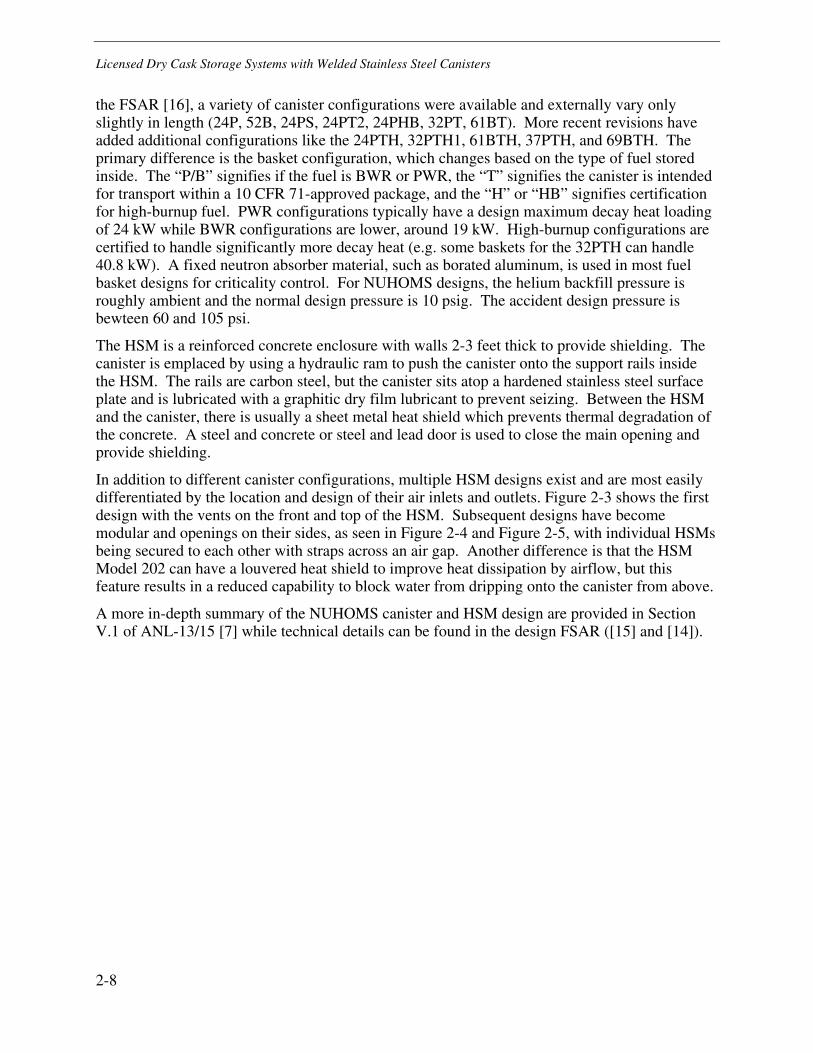
the FSAR [16], a variety of canister configurations were available and externally vary only slightly in length (24P, 52B, 24PS, 24PT2, 24PHB, 32PT, 61BT). More recent revisions have added additional configurations like the 24PTH, 32PTH1, 61BTH, 37PTH, and 69BTH. The primary difference is the basket configuration, which changes based on the type of fuel stored inside. The “P/B” signifies if the fuel is BWR or PWR, the “T” signifies the canister is intended for transport within a 10 CFR 71-approved package, and the “H” or “HB” signifies certification for high-burnup fuel. PWR configurations typically have a design maximum decay heat loading of 24 kW while BWR configurations are lower, around 19 kW. High-burnup configurations are certified to handle significantly more decay heat (e.g. some baskets for the 32PTH can handle 40.8 kW). A fixed neutron absorber material, such as borated aluminum, is used in most fuel basket designs for criticality control. For NUHOMS designs, the helium backfill pressure is roughly ambient and the normal design pressure is 10 psig. The accident design pressure is bewteen 60 and 105 psi.
The HSM is a reinforced concrete enclosure with walls 2-3 feet thick to provide shielding. The canister is emplaced by using a hydraulic ram to push the canister onto the support rails inside the HSM. The rails are carbon steel, but the canister sits atop a hardened stainless steel surface plate and is lubricated with a graphitic dry film lubricant to prevent seizing. Between the HSM and the canister, there is usually a sheet metal heat shield which prevents thermal degradation of the concrete. A steel and concrete or steel and lead door is used to close the main opening and provide shielding.
In addition to different canister configurations, multiple HSM designs exist and are most easily differentiated by the location and design of their air inlets and outlets. Figure 2-3 shows the first design with the vents on the front and top of the HSM. Subsequent designs have become modular and openings on their sides, as seen in Figure 2-4 and Figure 2-5, with individual HSMs being secured to each other with straps across an air gap. Another difference is that the HSM Model 202 can have a louvered heat shield to improve heat dissipation by airflow, but this feature results in a reduced capability to block water from dripping onto the canister from above.
A more in-depth summary of the NUHOMS canister and HSM design are provided in Section V.1 of ANL-13/15 [7] while technical details can be found in the design FSAR ([15] and [14]).

Licensed Dry Cask Storage Systems with Welded Stainless Steel Canisters
2-9
Figure 2-2 Standardized NUHOMS canister [16]
Figure 2-3 Original design of NUHOMS HSM [14]
Reproduced by permission of Transnuclear, Inc.
Reproduced by permission of Transnuclear, Inc.

Licensed Dry Cask Storage Systems with Welded Stainless Steel Canisters
2-10
Figure 2-4 HSM Model 80 (very similar to Model 102) with side vents visible [15]
Figure 2-5 Prefabricated HSM Model 202 with molded side vents at the bottom and top [17]
2.2.2 Advanced NUHOMS
The Advanced NUHOMS design [18] is very similar to the standardized NUHOMS design with the primary difference being modifications to the HSM, now called the Advanced HSM, to increase resistance to seismic events and with thicker shielding to reduce ISFSI dose. The design requires that at least three Advanced HSMs be tied together to reduce shifting and uplift during a seismic event as shown in Figure 2-6.
Reproduced by permission of Transnuclear, Inc.
Reproduced by permission of Transnuclear, Inc.

Licensed Dry Cask Storage Systems with Welded Stainless Steel Canisters
2-11
The canister is also modified slightly from the standardized NUHOMS design with the ability to store non-damaged fuel, damaged fuel, and control components in the same DSC (24PT1 and 24PT4). The 24PT1-DSC shell and cover plates are fabricated from ASME SA-240 Type 316 stainless steel. The shield plugs are carbon steel for 24PT1 and lead for 24PT4. The basket guide sleeves are Type 304 stainless steel while the spacer disks are carbon steel. The use of 316 on all components in the pressure boundary and welded to the pressure boundary contrasts with the use of 304 in the standardized design. The 24PT1 canister was designed for decay heat loads up to 14 kW, a design normal pressure of 10 psig, and a design accident pressure of 60 psig. The 24PT4 canister was designed for decay heat loads up to 24 kW, a normal design pressure of 20 psig, a design accident pressure of 100 psig and burnup up to 60 GWd/MTHM.
Figure 2-6 Advanced HSM showing minimum of three connected modules [18]
2.2.3 NUHOMS-HD
The NUHOMS-HD system [19] is designed to accept higher total heat loads and allow the storage of non-fuel assembly hardware in the same canisters as spent fuel. It is designed to accept the 32PTH DSC, which is very similar to the 24PTH included under the standard NUHOMS FSAR. The 32PTH can hold more assemblies than the 24PTH and can reject up to 34.8 kW of decay heat. The 32PTH DSC is fabricated from ASME SA-240 Type 304 stainless steel and shares the majority of its design details with the other NUHOMS family canisters, particularly the 24PTH. The design overpack is known as the HSM-H and can be seen in Figure 2-7. The heat shield within the HSM-H is louvered, which improves airflow, but the gaps between slats may allow water driven into the outlets to drip onto the canister. The operating pressure is about 5 psig per the FSAR.
Reproduced by permission of Transnuclear, Inc.

Licensed Dry Cask Storage Systems with Welded Stainless Steel Canisters
2-12
Figure 2-7 HSM-H showing louvered heat shields [19]
2.3 Vertical Canisters (Holtec, NAC, EnergySolutions)
Ventilated DCSS designs with vertical welded stainless steel canisters feature a canister surrounded by a cylindrical concrete and steel overpack. The overpack typically features four air inlets and outlets that are vertically offset from the canister to minimize radiation streaming. The canisters are generally loaded into the overpack by raising the transfer cask over the overpack and lowering the canister down. The canisters have a significantly thicker top than bottom to provide strength when lifting by the threaded lift points.
2.3.1 HI-STORM (Holtec)
The HI-STORM system [13] is the most common vertical canister design and consists of a multi-purpose canister (MPC) that can be used for storage and transport and a reinforced concrete overpack. The different MPCs (-24, -24E, -24EF, -32, -32F, -68, -68F, -68FF, and -68M) accept varying quantities of PWR and BWR fuel and can be enclosed in either a storage overpack or transport cask (HI-STAR). Either Boral or Metamic is used as a neutron absorber in the fuel baskets.
In the FSAR [13], the materials of the canister confinement boundary are specified as “Alloy X,” which may be any of 304, 304LN, 316, or 316LN, but all components of the confinement boundary must be constructed of the same stainless steel alloy. The structural components of the fuel basket are also stainless steel. The canister shell is 0.5 inches (13 mm) thick and is formed by rolling two sheets of stainless steel then joining them with single-V or double-V full penetration seam and girth welds [13]. The interior of the canister is backfilled with helium at 45 psig that can increase to a design operating pressure of 100 psig during storage.
A more in-depth summary of the HI-STORM canister and overpack design are provided in Section V.2 of ANL-13/15 [7] while technical details can be found in the design FSAR [13].
Reproduced by permission of Transnuclear, Inc.
Licensed Dry Cask Storage Systems with Welded Stainless Steel Canisters
2-13
2.3.1.1 Standard and Short Overpack
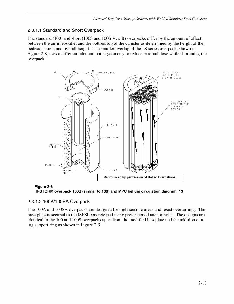
The standard (100) and short (100S and 100S Ver. B) overpacks differ by the amount of offset between the air inlet/outlet and the bottom/top of the canister as determined by the height of the pedestal shield and overall height. The smaller overlap of the –S series overpack, shown in Figure 2-8, uses a different inlet and outlet geometry to reduce external dose while shortening the overpack.
Figure 2-8 HI-STORM overpack 100S (similar to 100) and MPC helium circulation diagram [13]
2.3.1.2 100A/100SA Overpack
The 100A and 100SA overpacks are designed for high-seismic areas and resist overturning. The base plate is secured to the ISFSI concrete pad using pretensioned anchor bolts. The designs are identical to the 100 and 100S overpacks apart from the modified baseplate and the addition of a lug support ring as shown in Figure 2-9.
Reproduced by permission of Holtec International.

Licensed Dry Cask Storage Systems with Welded Stainless Steel Canisters
2-14
Figure 2-9 Detail of anchored version of HI-STORM overpack [13]
2.3.1.3 FW (Flood Wind) Overpack
The HI-STORM FW overpack [20] is designed to be particularly resistant to sustained flood and high wind conditions. The inlet and outlet designs are significantly different from other overpacks. Figure 2-10 shows the cylindrical annular inlets that are designed to minimize radiation streaming and disruption of the convective cooling flow by external winds. This allows the bottom of the canister to be lowered such that, during a worst-case flood that just covers the inlets, a substantial area of the canister will also be submerged and can use the floodwater as a heat sink. Guide tubes are welded to the inner shell of the overpack to center the MPC as it is lowered into the overpack and provide impact attenuation by crushing in the event of a tip-over.
The HI-STORM FW FSAR [20] also documents the MPC-37 and MPC-89, which are higher capacity canisters capable of handling higher heat loading: 47 kW of PWR fuel and 46 kW of BWR fuel, respectively. These canisters are also 7 inches larger in diameter than the other HI-STORM canisters described above but have the same backfill and operating pressure.
Reproduced by permission of Holtec International.
Licensed Dry Cask Storage Systems with Welded Stainless Steel Canisters
2-15
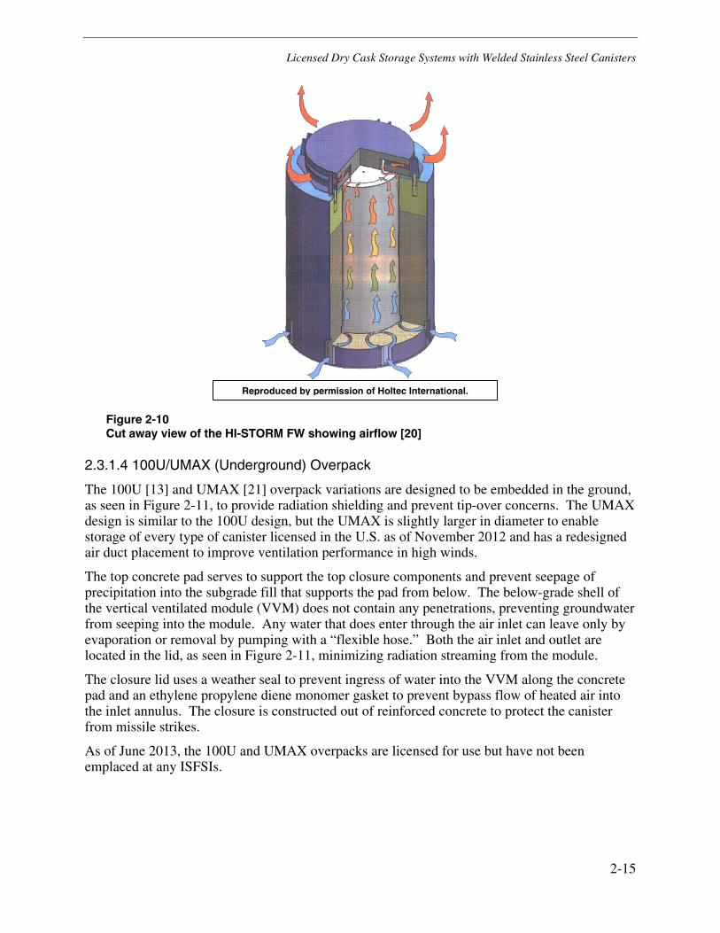
Figure 2-10 Cut away view of the HI-STORM FW showing airflow [20]
2.3.1.4 100U/UMAX (Underground) Overpack
The 100U [13] and UMAX [21] overpack variations are designed to be embedded in the ground, as seen in Figure 2-11, to provide radiation shielding and prevent tip-over concerns. The UMAX design is similar to the 100U design, but the UMAX is slightly larger in diameter to enable storage of every type of canister licensed in the U.S. as of November 2012 and has a redesigned air duct placement to improve ventilation performance in high winds.
The top concrete pad serves to support the top closure components and prevent seepage of precipitation into the subgrade fill that supports the pad from below. The below-grade shell of the vertical ventilated module (VVM) does not contain any penetrations, preventing groundwater from seeping into the module. Any water that does enter through the air inlet can leave only by evaporation or removal by pumping with a “flexible hose.” Both the air inlet and outlet are located in the lid, as seen in Figure 2-11, minimizing radiation streaming from the module.
The closure lid uses a weather seal to prevent ingress of water into the VVM along the concrete pad and an ethylene propylene diene monomer gasket to prevent bypass flow of heated air into the inlet annulus. The closure is constructed out of reinforced concrete to protect the canister from missile strikes.
As of June 2013, the 100U and UMAX overpacks are licensed for use but have not been emplaced at any ISFSIs.
Reproduced by permission of Holtec International.

Licensed Dry Cask Storage Systems with Welded Stainless Steel Canisters
2-16
Figure 2-11 Cut away view of the HI-STORM 100U [13]
2.3.2 NAC-MPC and NAC-UMS
The principal components of the NAC MPC [22] and UMS [23] systems are the transportable storage canister (TSC) and the vertical concrete overpack.
The MPC canister design has slight variations for each of the three ISFSIs for which it has been used, depending on fuel size. By FSAR revision 9 [22], the canister confinement boundary is fabricated from dual certified 304/304L stainless steel; previously, 304L was specified. The PWR canister shell is 0.625 inches thick and houses a fuel basket with 26 or 36 fuel tubes that are fabricated of and supported by stainless steel. The BWR shell is 0.5 inches thick and houses a fuel basket of 68 fuel tubes including 32 damaged fuel cans and 36 undamaged fuel assemblies. Neutron absorber plates are used along the fuel tubes to control criticality, and aluminum heat transfer disks are used to supplement the convective cooling by the helium backfill. The MPC design is initially backfilled with helium to ambient pressures and has an operating pressure of 12 psig. The 26 assembly variation is rated for 12.5 kW, and the 36 assembly version is rated for 17.5 kW. The 68 assembly BWR version is rated for 4.5 kW.
The UMS canister design is constructed of a 0.625 inch Type 304L rolled shell that is welded to a Type 304L baseplate and outer structural lid. A thicker Type 304 shield lid is located interior to the structural lid and is supported by a 304 support ring that is welded to the shell. A different fuel basket is used to store either 24 PWR or 56 BWR fuel assemblies. The fuel tubes are constructed of Type 304 and lined with neutron absorber plates. The support disks are Type 630 stainless steel in the PWR configuration and ASME SA-533 Type B carbon steel in the BWR configuration. Aluminum 6061-T651 heat transfer disks facilitate heat transfer to the canister
Reproduced by permission of Holtec International.

Licensed Dry Cask Storage Systems with Welded Stainless Steel Canisters
2-17
surface. The canister is initially backfilled with helium to ambient pressures and has an operating pressure of 15 psig. The UMS system is rated for a maximum of 23 kW of decay heat.
For both the MPC and UMS designs, the overpack is very similar with a steel inner liner, reinforced concrete shielding, and four sets of air inlets and outlets. The wall thickness is approximately 30 inches. As seen in Figure 2-12 and Figure 2-13, the canister sits atop a steel pedestal which provides impact attenuation in the event of a cask drop. The canisters are loaded vertically into the overpacks as shown in Figure 2-13 with the bottom shield doors of the transfer cask remaining closed until the transfer cask is atop the overpack.
A more in-depth summary of the MPC and UMS canister and overpack designs is provided in Section V.4.1.2 and V.4.1.3 of ANL-13/15 [7] while technical details can be found in the design FSARs ([22] and [23]).
Figure 2-12 Cutaway view of UMS overpack [23]
Reproduced by permission of NAC International Inc.

Licensed Dry Cask Storage Systems with Welded Stainless Steel Canisters
2-18
Figure 2-13 Section view of the MPC as canister is loaded into the overpack [22]
2.3.3 MAGNASTOR (NAC)
The MAGNASTOR system [24] is designed by NAC to handle higher burnup and decay heat assemblies.
The MAGNASTOR TSC consists of a 0.5 inch thick shell and 2.75 inch thick bottom weldment, both fabricated from dual certified Type 304/304L. The top lid and vent port closures are fabricated from Type 304 stainless steel. The fuel basket holds 37 PWR or 87 BWR fuel assemblies with a maximum decay heat of 35.5 and 33 kW, respectively. Fuel assemblies up to a burnup of 60 GWd/MTHM can be stored. The fuel basket is fabricated from electroless nickel coated carbon steel. Neutron absorber panels are used between fuel tubes to control reactivity. The TSC has a design normal pressure of 110 psig and a design accident pressure of 250 psi.
As seen in Figure 2-14, the concrete overpack design of the MAGNASTOR system has four air inlets that are shorter and broader than the UMS and MPC systems, but is otherwise much the same. The bottom steel support pedestal is much shorter since the low profile inlets are of less concern for streaming of radiation. Carbon steel standoffs center the TSC in the concrete cask and support it in the event of a tip-over.
A more in-depth summary of the MAGNASTOR canister and overpack design are provided in Section V.4.1.4 of ANL-13/15 [7] while technical details can be found in the design FSAR [24].
Reproduced by permission of NAC International Inc.

Licensed Dry Cask Storage Systems with Welded Stainless Steel Canisters
2-19
Figure 2-14 MAGNASTOR Design [24]
2.3.4 FuelSolutions W150 Overpack with W74 Canister (EnergySolutions)
Currently, the FuelSolutions ([25] and [26]) DCSS, designed by EnergySolutions, is used only at the Big Rock Point ISFSI. The confinement boundary of the W74T canisters in service is fabricated from Type 304 stainless steel and consists of a 0.625 inch thick shell, 1.0 inch thick bottom closure plate, and 1.0 and 2.0 inch thick top closure plates [26]. Below the bottom closure, an extension is welded to the canister which encloses a steel shield plug. The fuel basket is two levels, as seen in Figure 2-15, and can hold a maximum of 64 Big Rock Point fuel assemblies with the center five positions unused on each level. The canister design internal pressure of backfilled helium is 10 psig.
The FuelSolutions W150 overpack design consists of stacked prefabricated segments which are held together by eight steel tie rods and molded shear keys as seen in Figure 2-15. The FuelSolutions overpack is designed to be loaded in either the vertical or horizontal orientation. Its support and guide rails are capable of supporting the canister in either configuration. Subsequent to horizontal loading, the overpack containing the canister is upended and moved to its storage location on the ISFSI pad.
A more in-depth summary of the FuelSolutions canister and overpack design is provided in Section V.8 of ANL-13/15 [7] while technical details can be found in the design FSARs ([25] and [26]).
Reproduced by permission of NAC International Inc.

Licensed Dry Cask Storage Systems with Welded Stainless Steel Canisters
2-20
Figure 2-15 W74 design canister [26] and the FuelSolutions W150 overpack [25]
Reproduced by permission of EnergySolutions.

3-1
3 FAILURE MODES AND EFFECTS ANALYSIS (FMEA)
3.1 FMEA Structure and Regulatory Criteria
Dry cask storage has recently garnered significant attention as lifetimes are extended past the first license period due to the delayed transition to geological storage. Literature reviews and operating experience (OE) summaries on atmospheric degradation of stainless steels were considered to determine the relevant failure modes and mechanisms ([27], [28], and [29]).
3.1.1 Structure and Process
The FMEA process is structured to systematically identify the potential failure modes, their relative likelihood, and their consequences to a system [30]. The key steps in the process are as follows:
1. Determine the components relevant to the scope of the FMEA and the definition of failure.
2. Brainstorm potential modes of failure.
3. Determine what mechanisms might lead to these modes of failure and what factors may contribute to susceptibility.
4. Consider how the various modes of failure may affect the system and what additional components may be degraded.
5. Assign rankings of likelihood, severity, and detectability to the various steps in the failure based on engineering judgment and current knowledge of the issue.
Section 3.1.2 describes the regulatory requirements relevant to materials aging and degradation of the canister. These requirements inform the stages of the FMEA (i.e. mechanisms, modes, and effects). Section 3.2 summarizes the degradation mechanisms, failure modes, effects, and key parameters identified by the FMEA. In Section 3.3, the FMEA results are presented in a table describing the mechanisms which lead to each mode of failure and a flowchart to provide a visual representation of the failure paths. The conditions and events which may lead to a penetration of confinement are also presented as a fault tree analysis. Technical details on the various mechanisms and their designated FMEA rakings are provided in Section 4.
Although the point of “failure” in this FMEA is based on regulatory requirements, it should be recognized that release of radioactivity will not necessarily occur if every regulatory requirement is not met. For example, loss of confinement does not necessarily mean that radiation will be released to the environment. The regulatory requirements are utilized in this FMEA to establish distinct stages in the chain of possible degradation conditions in order to assess the potential consequences of canister degradation. Of the regulatory requirements listed in Section 3.1.2, canister aging degradation mechanisms could directly affect the requirement to maintain the confinement boundary integrity and could indirectly affect the other requirements.

Failure Modes and Effects Analysis (FMEA)
3-2
The focus of this FMEA is to determine the credible mechanisms that may lead to degradation during storage of the welded stainless steel canisters used in dry cask storage systems. The range of aging degradation failure modes and mechanisms considered are those which initiate due to environmental conditions surrounding the canister and are informed by chapters on atmospheric and stainless steel corrosion in the ASM Handbook ([38] and [59]) as well as other literature sources. Not all mechanisms reviewed are explicitly considered in this FMEA; only modes and mechanisms considered applicable to the canister environment are included. The potential for fuel degradation and radiation releases that could result from degradation of the canisters is covered in the context of consequences of canister failure modes. As discussed in Section 2, the canister materials exposed to the environment are austenitic stainless steels of Type 304, 304L, 316, 316LN, and possibly 304LN; and the associated weld metals. A failure in the top structural lid, enclosure ring, or the associated welds also requires a second sequential failure in another component to lead to a loss of confinement. A single failure in the shell or, for some vertical designs, the bottom lid leads to a loss of confinement. Much of the FMEA discussion considers the thin cylindrical shell to be the component with the greatest susceptibility because of the redundant top lid seal and because the bottom lid is typically 3-5 times thicker than the shell and is sometimes backed by a welded shield lid. It is unlikely that failure of the external welds on the canister top would lead to the inner weld being exposed to significant chlorides or other aggressive species, and combined shield and structural top lids, when used, are about 15 times thicker than the shell. The seam and girth welds on the shell (including the exterior of the shell in the vicinity of the shell to lid partial penetration weld) are expected to have significant tensile stress while being much thinner than other potentially susceptible locations; consequently, these locations are expected to have the greatest likelihood of through-wall material degradation.
3.1.2 Regulatory Requirements
The primary purpose of dry cask storage is to alleviate the lack of space in spent fuel pools while awaiting final disposition via long-term storage or fuel reprocessing. According to NUREG-1927 [31], dry cask storage systems are designed to protect and confine spent fuel assemblies, and the safety functions of their components are categorized into the following:
• Criticality Control – The DCSS prevents the stored fuel from reaching criticality during normal and accident conditions per 10 CFR 72.124(a); the Standard Review Plan (SRP), NUREG-1536 Rev. 1 [32], requires that FSAR analyses ensure the neutron multiplication factor, keff, remains below 0.95 during these normal and accident conditions.
• Radiation Shielding – The DCSS maintains dose rates at ISFSI below those mandated by 10 CFR 72.104 and 72.106. Beyond the ISFSI controlled area boundary, annual total effective dose must not exceed 0.25 mSv (25 mrem) to the whole body, and accident dose must not exceed the total effective dose equivalent of 50 mSv (5 rem). Alternate, organ-specific dose limits can be found in the aforementioned regulations.
• Confinement Boundary – The DCSS is designed to maintain a pressure boundary which is capable of retaining the radioactive material during normal and accident conditions per 10 CFR 72.236(l).
• Heat Transfer – To maintain the cladding temperature below the SRP temperature limit of 400°C throughout the period of dry storage, the DCSS provides sufficient passive cooling in the event of normal conditions, off-normal conditions, and time-limited accident conditions.

Failure Modes and Effects Analysis (FMEA)
3-3
• Structural Integrity – Components providing structural or functional support to components that are important to safety should remain capable of completing their function.
• Fuel Retrievability – The DCSS is designed to allow ready retrieval of fuel using normal means after exposure to normal and off-normal conditions per Section 12.4.5 of the SRP and 10 CFR 72.122(l).
These regulatory requirements are also used as the failure criteria for this FMEA. Within the scope of this FMEA, only those failures which result from aging-related degradation of the canister are considered.
3.1.3 10 CFR 72 Reporting Requirements
Many of the events considered in this report would involve reporting under NRC regulation. 10 CFR 72.74 and 72.75 specify the events which require reporting to the NRC and the timeframe within which the report must be filed by telephone. A written report must subsequently be filed within 60 days of the event.
All emergencies, as defined by the licensee’s emergency plan, must be reported within an hour of declaring an emergency. Any events for which a news release is planned, which may include a release of radiation to the environment, must be reported within four hours of occurrence or discovery. Discovery of any defects in components that are important to safety or any reduction in the effectiveness of confinement must be similarly reported within 8 hours, while failure of important to safety equipment to function as designed must be reported within 24 hours.
NEI-99-01 [33] serves as the basis for most plant Emergency Action Levels and specifies that damage to a loaded cask confinement boundary requires a notification of unusual event.
3.2 FMEA Summary
3.2.1 Failure Modes Overview
In this FMEA, the credible canister degradation failure modes almost exclusively affect the regulatory requirement to maintain a confinement boundary. The most credible failure mode identified is a loss of confinement boundary integrity by through-wall cracking. Other considered failure modes were loss of confinement by through-wall corrosion pitting, and loss of canister structural integrity due to a large part-depth or through-wall crack growing to the size needed for plastic collapse of the shell. A part-depth flaw alone does not affect the function of the canister, loss of confinement, or any of the other criteria in Section 3.1.2; it is not a failure mode unless it grows to critical length and ruptures. Also note the following:
• Overpack degradation was not considered within the scope of this FMEA. If substantial overpack degradation were to occur, it could lead to significant loading of the canister by concrete rubble and to increased cladding temperatures by loss of airflow. The design accident conditions, which are considered in this FMEA, contain scenarios that bound both of these examples.
• Rupture of fuel rods due to design basis accidents, such as canister tip-overs, is analyzed by canister FSARs and is acceptable per the SRP, NUREG-1536R1 [32], so it is not part of the scope of this FMEA.

Failure Modes and Effects Analysis (FMEA)
3-4
• Failure of the support rail in horizontal designs could impact canister removal from the DCSS for transport, but is considered only as a potential source of mechanical stress in this FMEA because it does not result in degradation of the canister by means other than a drop with conditions bounded by existing FSAR analyses.
3.2.2 Material Degradation Mechanisms Overview
The canister degradation mechanisms are divided into those which lead to a failure in confinement due to a tight crack and those which lead to a more gross penetration of the confinement boundary. The through-wall penetration size, and therefore the ability of particulates to traverse the penetration, affects the potential consequences.
The most likely degradation mechanism at marine sites is chloride-induced stress corrosion cracking, which requires the presence of an aqueous chloride solution, a source of stress (such as weld residual stress), and a susceptible material (e.g. austenitic stainless steels). The chloride solution may form as a result of the deliquescence of sea salt deposits on the canister surface or due to the ingress of rain dissolving deposited salts. Other potential mechanisms include pitting, crevice corrosion, microbiologically induced corrosion, and intergranular attack. Degradation originating at the interior surface of the canister is considered not credible due to the predominantly dry, inert internal atmosphere. The loss of confinement boundary is generally a prerequisite for failures in the function of canister internals such as fuel cladding, so mechanisms that lead to degradation of the canister internals are considered in the discussion of failure effects.
As part of the FMEA, a listing of the key parameters that control the likelihood of each credible mechanism that might lead to failure of the canister is presented in Table 3-1. Note that the presence of some of these parameters varies over the confinement boundary area, which may limit the susceptible area (e.g. CISCC may be limited to weld areas by the need for sufficient tensile stress to cause cracking). Not included in Table 3-1 are the possible degradation mechanisms for components excluded from the scope of the FMEA such as the overpack and support rail.
The presence, magnitude, and type of stress in a given component determine whether it will fracture and rupture due to material degradation and aging and also strongly affect its susceptibility to stress corrosion cracking. The design basis load cases considered in the canister FSARs will be used in future efforts to define criteria for determining the susceptibility of stainless steel canisters to cracking. For degradation mechanisms and stresses which are dependent on temperature, it should be noted that the canister decay heat loading decreases substantially during the initial decades of storage relative to as-loaded conditions. After 20 years in dry storage, the temperature of fuel cladding can be expected to be about two-thirds what it was at loading, relative to the ambient temperature [34].

Failure Modes and Effects Analysis (FMEA)
3-5
Table 3-1 List of key parameters for confinement boundary failure mechanisms
Plausible Canister Degradation Mechanism
Key Parameters
CISCC
Deposited chlorides (quantity and associated cation)
Presence of water (surface humidity above DRH, rain ingress, etc.)
Residual or applied stress
Surface temperature
Material condition (microstructure, sensitization, and fabrication defects)
Composition of surface deposits (e.g., presence of free iron, dust, etc.)
Cold work and surface condition (grinding, polishing, etc.)
Presence of crevices (macrocrevices and microcrevices due to grinding, etc.)
Pitting Corrosion
Quantity and type of aggressive species (e.g., chlorides)
Presence of water (deliquescence above DRH, rain ingress, etc.)
Composition of surface deposits (e.g., presence of free iron, dust, etc.)
Surface temperature
Surface solution pH
Material condition (presence of inclusions, sensitization, fabrication defects)
Crevice Corrosion
Occluded area (geometry or impermeable deposit)
Presence of water (surface humidity above DRH, rain ingress, etc.)
Quantity and type of aggressive species (e.g., chlorides, graphite)
Surface temperature
Crevice solution pH
Microbiologically Induced Corrosion
Presence of water or very high relative humidity
Source of nutrients (CO2, dust, etc.)
Radiation resistant microbes
Deposition of bacterial colony
Low surface temperature
Intergranular Attack
Presence of water (surface humidity above DRH, rain ingress, etc.)
Very low pH solution
Sensitized microstructure

Failure Modes and Effects Analysis (FMEA)
3-6
3.2.3 Failure Effects Overview
Subsequent to loss of canister confinement, the helium backfill would escape the canister, potentially entraining and releasing radioactive gases or particles from the canister. After depressurization, the remaining helium would gradually be displaced as air and moisture enter due to diurnal and seasonal thermal expansion. Considering the criteria in Section 3.1.2, the potential effects of the new environment surrounding the stored fuel assemblies include: (1) release of radiation following loss of fuel cladding integrity, (2) exceeding cladding temperature limits due to loss of helium backfill and consequential degradation of heat transfer, and (3) difficulty in removal of fuel from the canister due to gross fuel assembly degradation or fuel basket deformation. A criticality event is considered not credible due to the non-mechanistic changes in stored fuel geometry required to lead to criticality even after the ingress of moderator as discussed in Section 4.4.5.
The cladding integrity of fuel which is not canned should be maintained to avoid a potential release of radioactive material that may exceed regulatory limits. Potential cladding degradation mechanisms include fuel pellet swelling, creep, and cracking due to hydrides.
Table 3-2 summarizes the key parameters which may credibly lead to degradation of the fuel assemblies loaded in the canister once the confinement boundary is penetrated and the helium backfill begins escaping.
Table 3-2 Summary of key parameters for fuel assembly degradation mechanisms
Fuel Assembly Degradation Mechanism
Key Parameters
Fuel Pellet Swelling
Presence of oxygen
Fuel pellet temperature
Fuel burnup
Cladding Oxidation Presence of oxygen
Fuel pellet temperature
Cladding Creep
Cladding temperature
Stress in cladding
Cladding microstructure
Radial Hydride Reorientation (or Blister
Formation)
Large cladding temperature cycling
Elevated cladding hoop stress
Hydrogen concentration in cladding
Hydrogen embrittlement
Large cladding temperature cycling
High burnup fuel assembly
Hydrogen concentration in cladding
Cladding annealing Very elevated cladding temperature
Failure Modes and Effects Analysis (FMEA)
3-7
3.3 FMEA Flowchart and Tables
3.3.1 FMEA Flowchart
The failure mode flowchart in Figure 3-1 illustrates the overall failure process, starting from the key parameters and contributing factors at the bottom of the figure to the canister and internals aging degradation mechanisms in the white ovals to the failure modes that are designated by the colored rectangles. Above these, the potential effects of a failure in confinement are shown. The flowchart visually shows the progression of conditions from an intact canister to the terminating consequences. Pathways that are judged to be non-credible are shown with red arrows and strike-through font, although some non-credible degradation pathways have been omitted for clarity. Circles with letter designations are used as jump points to link the factors which affect pathways in different sections of the flowchart.
Figure 3-2 depicts an example progression through the flow chart with side branches that are not followed shown in grey. The pathway begins with a contributing parameter, “Sea Spray Aerosol,” at the bottom which leads to “Deposited Chlorides” then, combined with other parameters like aqueous conditions and residual stress, generates the “Necessary Conditions for CISCC to Develop.” Presence of the necessary conditions could cause “Chloride Induced Stress Corrosion Cracking” initiation and growth after a period of time. One possibility is for CISCC “Growth of a Crack Transverse to Weld” leading to a “Tight Through-Wall Penetration” and canister failure. This would cause a “Release of Helium Backfill” that may cause other cascading consequences and could directly cause the “Release of Radioactive Materials” (see circle “E” path) if the fuel cladding is not intact. For information on the relative importance of each parameter, refer to the text in Section 4 and the Fault Tree Analysis in Figure 3-3.
3.3.2 FMEA Fault Tree Analysis
To show the relative importance of the parameters and the combinations which lead to the various degradation pathways, the FMEA flowchart has been recast in part as a fault tree with the end condition being the penetration of the confinement boundary. The fault tree shown in Figure 3-3 is derived from the lower section of the flowchart, but omits contributing factors, and considers only those events and conditions which are required for failure to occur. In a fault tree analysis ([35] and [36]), logic gates specify the combination of basic events and conditions that allow degradation to progress further. If any of the conditions leading into an OR gate occurs, the subsequent condition may result whereas all of the conditions leading to an AND gate must occur to allow the possibility of the subsequent condition. The most beneficial pathways for mitigation techniques to address are determined by examining which conditions enable the most degradation pathways and are therefore of greater importance.
One advantage of a fault tree representation of the factors is the ability to examine “cut sets,” which are the combination of basic parameters that can cause a failure. An example cut set of the parameters which can lead to canister confinement boundary failure is depicted in Figure 3-4. The base parameters in this example cut set are “Sea Spray Aerosol,” “Fabrication or Weld Residual Stresses,” “Canister Surface Temperature,” and “Humidity Greater than DRH.”

Failure Modes and Effects Analysis (FMEA)
3-8
Figure 3-1 FMEA Flowchart for material degradation of stainless steel canisters of DCSSs
Tight TW Penetration of
CanisterFailure Mode:Retrievability
Aging Degradation
Cold Work(Forming, Grinding)
Sensitization of Stainless Steel
Fabrication or Weld Residual
Stresses
Deposited Chlorides
Canister Surface Temperature
Humidity Greater than DRH
Aggressive Species Surface Contamination
External Water
Pitting Corrosion
Manufacturing Defects
Material Condition
Environmental Condition
Deliquescence
Failure Mode:Confinement
Failure Mode:Temperature
Intermediate Condition
Growth of Crack Transverse to
Weld
Growth of Crack Along Weld
Growth of Base Metal Crack
Microbiologically Induced Corrosion
Intergranular Attack
Sensitized Microstructure
Crevice Corrosion
Not Credible
B
Chloride Induced Stress Corrosion
Cracking
ID Compressive Fabrication Stress
Radiolytic Production of
Aggressive Species
Transportation Load
Handling Load
Crevice Geometry/Impermeable
Surface Deposit
B
Crack Growth by Fatigue
Coalescence of PD Flaws to
Critical Length
Growth of PD Flaw Along Support Rail
Growth of Pit
Thermal Cyclical Stresses
Very Low pH Deliquescent
Solution
Nutrients and Colonizing
Microbes Present
C
C
Local Aqueous Conditions
Corrosion Degradation of Fuel
Basket
Ingress of H2O and O2
Release of He Backfill
Loss of Fuel Cladding
Structural Integrity
Swelling of Pellets in Non-Intact Fuel
Radioactive Material Release to Atmosphere
Stored Fuel Geometry Change
Cladding CreepCladding Oxidation
E
Criticality Event
Zircaloy Cladding SCC
Hydrogen Induced Degradation
Cladding Annealing
Significant Release of Radioactive Particulates
A
Drop Accident Stress Load
Radiolytic Generation of Aggressive Species
Flood or Transport Accident
E
Gouge in Surface During Loading
Airborne HCl & Cl2 Sea Spray Aerosol
D
D
Fire or Vent Blockage Event
Canister Accident Loads
Failure Mode:Criticality
Failure Mode:Dose Increase
CladdingSensitization
Canister Rupture
Stress or Loading
Fission Gas Release to Canister
Ingress of Rain Condensate Dripping
Surface Iron Contamination
C
Grain Drop Out
Gross TW Penetration of
Canister
A
Radiolytic Generationof H2 from Water in
Canister
Lightning/Ignition Source
Failure of Support Rail
Canister Cavity Filled with Moderator
Generation of Fuel Fines
Cladding Temperature
Increases
Anthropogenic Chloride SourcesGalvanic Potential
Canister Misaligned with
Overpack Opening
F
IGSCC of SS Cladding
Internal Hydrogen Explosion
Spallation of Crud
Neutron Poison Degradation
Increased Potential for
Corrosion Initiation
Necessary Conditions for
CISCC to Develop
Not in Scope
Lack of Fusion Flaw
Transportation Cyclical StressesPre-Existing Crack
Growth of TW Crack to Critical
Length
F
A
F
High Burnup Fuel
Contamination by Iron or Other Species
during Manufacturing
Internal Pressure
Loaded Non-Intact Fuel
Generation of H2 by Oxidation of
Zirconium by Water

Failure Modes and Effects Analysis (FMEA)
3-9
Figure 3-2 Example path through FMEA Flowchart
Tight TW Penetration of
Canister
Fabrication or Weld Residual
Stresses
DepositedChlorides
Growth of Crack Transverse to
Weld
Growth of Crack Along Weld
Growth of BaseMetal Crack
Chloride Induced Stress Corrosion
Cracking
C
Local Aqueous Conditions
Release of He Backfill
Radioactive Material Release to Atmosphere
E
Cladding SCC
E
Sea Spray Aerosol
Fire or VentBlockage Event
Anthropogenic Chloride Sources
Hot Cell Rot
Spallation of Crud
Necessary Conditions for
CISCC to Develop
A
Loss of FuelCladding
Structural Integrity
Cladding Creep
Fission Gas Release to Canister
CladdingTemperature
Increases
Loaded Non-Intact Fuel

Failure Modes and Effects Analysis (FMEA)
3-10
Figure 3-3 Fault Tree Analysis for through-wall penetration of canister and loss of confinement integrity
Aging Degradation
Material Condition
Environmental Condition
Intermediate Condition
Stress or Loading
Confinement Boundary Failure
Tight TW Penetration of
Canister
Fabrication or Weld Residual
Stresses
Deposited Chlorides
Canister Surface Temperature
Humidity Greater than DRH
Surface Contamination
Pitting Corrosion
Deliquescence
Failure Mode:Confinement
Growth of Crack Transverse to
Weld
Growth of Crack Along Weld
Growth of Base Metal Crack
Microbiologically Induced Corrosion
Intergranular Attack
Sensitized Microstructure
Crevice Corrosion B
Chloride Induced Stress Corrosion
Cracking
ID Compressive Fabrication Stress
Transportation LoadHandling Load
Crevice Geometry/Impermeable
Surface Deposit
Crack Growth by Fatigue
Growth and Coalescence of PD Flaws to Critical
Length
Growth of Axial Crack Along Support Rail
Growth of Pit
Thermal Cyclical Stresses
Very Low pH Deliquescent
Solution
Nutrients and Colonizing Microbes
Present
C
Local Aqueous Conditions
Growth of TW Crack to Critical Length
A
Drop Accident Stress Load
Fatigue Growth During Transport
Airborne HCl & Cl2 Sea Spray Aerosol
Canister Rupture
Ingress of Rain Condensate Dripping
C
Grain Drop Out
Gross TW Penetration of
Canister
A
A
Anthropogenic Chloride Sources
OR
OR
OR
OR
OR
AND
OR
AND
OR
OR
AND
AND
C
ANDAND
OR
AND
AND
OR
AND
D
D
AND
OR
Transportation Cyclical Stresses
Pre-Existing Crack
OR
B
Not Credible
Internal Pressure
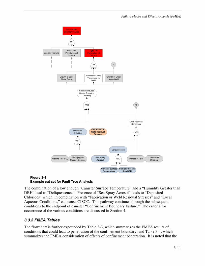
Failure Modes and Effects Analysis (FMEA)
3-11
Figure 3-4 Example cut set for Fault Tree Analysis
The combination of a low enough “Canister Surface Temperature” and a “Humidity Greater than DRH” lead to “Deliquescence.” Presence of “Sea Spray Aerosol” leads to “Deposited Chlorides” which, in combination with “Fabrication or Weld Residual Stresses” and “Local Aqueous Conditions,” can cause CISCC. This pathway continues through the subsequent conditions to the endpoint of canister “Confinement Boundary Failure.” The criteria for occurrence of the various conditions are discussed in Section 4.
3.3.3 FMEA Tables
The flowchart is further expounded by Table 3-3, which summarizes the FMEA results of conditions that could lead to penetration of the confinement boundary, and Table 3-4, which summarizes the FMEA consideration of effects of confinement penetration. It is noted that the
Tight TW Penetration of
Canister
Fabrication or Weld Residual
Stresses
Deposited Chlorides
Canister Surface Temperature
Humidity Greater than DRH
Deliquescence
Growth of Crack Transverse to
Weld
Growth of Crack Along Weld
Growth of Base Metal Crack
Chloride Induced Stress Corrosion
Cracking
C
Local Aqueous Conditions
Airborne HCl & Cl2Sea Spray
AerosolIngress of Rain Condensate
Dripping
A
Anthropogenic Chloride Sources
OR
AND
OR
OR
AND
Confinement Boundary Failure
Canister RuptureGross TW
Penetration of Canister
OR

Failure Modes and Effects Analysis (FMEA)
3-12
conditions in Table 3-4 could only occur after a failure mode in Table 3-3, and consequently the frequencies in Table 3-4 are conditional on prior confinement penetration. The individual degradation mechanisms and failure modes are further discussed in Sections 4.2, 4.3, and 4.4. For each failure mode and effect, the detectability, severity, and frequency of occurrence are rated according to the following category definitions:
Detectability
• Predictable – The degradation cannot be directly detected, but measurement and analysis of other parameters indicates with reasonable confidence whether degradation will or will not occur.
• Detectable – The degradation can be detected using presently available technologies.
• Possibly Detectable – The degradation could be detected, but the technology is not yet proven, or the detectability is hampered by accessibility issues.
• Not Detectable – The degradation cannot be detected and calculations cannot reliably predict occurrence.
Severity
• Minimal – The failure affects the function of the component and may release some radioactive gasses but is unlikely to release radioactive particulates.
• Moderate – The failure of the component might release radioactive gasses and particulates.
• Significant – The failure of the component would likely release radioactive gasses and particulates.
• Very Significant – The failure of the component would likely release substantial quantities of radioactive gasses and particulates.
Frequency
• Not Credible – There is a strong technical basis for concluding the degradation pathway is not a significant factor within the extended lifetime of the DCSS canister.
• Very Minimal – The degradation is possible, but has a remote probability of occurrence, even at a highly susceptible ISFSI.
• Minimal – The degradation is possible, but is not expected to occur at highly susceptible ISFSIs.
• Moderate – The degradation might occur on some canisters at highly susceptible ISFSIs.
• Significant – The degradation is likely to occur on some canisters at highly susceptible ISFSIs within the extended lifetime.
In addition to the rankings, the tables provide short explanations for the detectability designation and the effects of each failure mode and degradation mechanism. It is emphasized that the frequency rankings are with consideration of the extended storage lifetime (e.g., 120 years of storage). The frequency (i.e., probability) of occurrence of a failure mode/effect may be substantially lower for the initial decades of storage.

Failure Modes and Effects Analysis (FMEA)
3-13
Table 3-3 FMEA Summary Table for causes of through-wall penetration of canister and loss of confinement integrity
Notes: 1) Environmentally assisted fatigue was not considered. 2) Confinement failure means that there is a release of any fission gases in the canister and the helium backfill is replaced over time by humid air. 3) Note that while CISCC is a credible degradation mechanism, this combination of failure mode and mechanism is not credible.
Component Failure Mode Material Degradation Mechanism(1) Causes/Enabling Conditions Contributing FactorsDirect Failure Effects or Consequences(2) Severity
Detectability of Degradation Prior to Failure
Detectability of Failure Frequency
Tight through-wall flaw
CISCCStressSurface chlorides above thresholdAqueous conditions at surface
See Table 3-1Penetration of confinement.
Possibly Detectable - occurrence of through-wall penetration likely detectable by NDE in some locations; depends on design details
Moderate; Significant at marine ISFSIs
4.3.1 4.2.1
Crevice corrosionCrevice geometry or impermeable depositAqueous conditions at surface
Presence of aggressive species (e.g. Cl-)See Table 3-1
Not Detectable - crevice geometry makes NDE of area inherently difficult
Moderate 4.2.3
Pitting corrosionAqueous conditions at surface
Presence of aggressive species (e.g. Cl-)See Table 3-1
Detectable - visually detectable in some locations; depends on design details
Moderate 4.2.2
Microbiologically induced corrosion (MIC)
Significant presence of nutrientsInitial colony of bacteriaSurface RH > 60% or aqueous conditions
See Table 3-1Detectable - visually detectable in some locations; depends on design details
Very Minimal 4.2.4
Grain drop out Intergranular attack (IGA)
Aqueous conditions at surfacePresence of extremely aggressive species
(e.g. NH4HSO4)
Sensitized microstructure
See Table 3-1
Possibly Detectable - occurrence of through-wall penetration likely detectable by NDE in some locations; depends on design details
Very Minimal 4.3.2 4.2.5
CISCCStressSurface chlorides above thresholdAqueous conditions at surface
See Table 3-1
Possibly Detectable - occurrence of through-wall penetration likely detectable by NDE in some locations; depends on design details
Not Credible(3) 4.2.1
Crevice corrosionCrevice geometry or impermeable depositAqueous conditions at surfacePresence of aggressive species (e.g. Cl-)
See Table 3-1Not Detectable - crevice geometry makes NDE of area inherently difficult
Very Minimal 4.2.3
Thermal cycle fatiguePre-existing crackSignificant thermal expansion mismatchLarge temperature cycling
See Table 3-1
Possibly Detectable - occurrence of through-wall penetration likely detectable by NDE in some locations; depends on design details
Not Credible 4.2.6
CISCCStressSurface chlorides above thresholdAqueous conditions at surface
See Table 3-1
Possibly Detectable - occurrence of through-wall penetration likely detectable by NDE in some locations; depends on design details
Very Minimal 4.2.1
Crevice corrosionCrevice geometry or impermeable depositAqueous conditions at surfacePresence of aggressive species (e.g. Cl-)
See Table 3-1Not Detectable - crevice geometry makes NDE of area inherently difficult
Very Minimal 4.2.3
Fatigue crack growthPre-existing through-wall crackCyclical transportation loading
See Table 3-1Predictable - if the crack is known, then prediction of crack growth during transport is straight forward.
Minimal App. B
Section of Discussion
Penetration of confinement. Possible release of some radioactive particles.
4.3.2
Detectable - failure may not be visually apparent. However, measurement of the speed of sound through the canister cavity or measurement of the vertical temperature gradient could detect the failure. For a high degree of certainty, baseline measurements prior to failure are desirable.
Significant
Growth and rupture of large part-depth flaw
Penetration of confinement. Release of some radioactive particles with the potential for bulk debris release.
4.3.3
Minimal
Growth of through-wall flaw to critical size
Penetration of confinement. Release of some radioactive particles with the potential for bulk debris release.
Gross through-wall penetration
Canister Stainless
Steel Confinement
Boundary

Failure Modes and Effects Analysis (FMEA)
3-14
Table 3-4 FMEA Summary Table for effects of through-wall penetration of canister and loss of confinement integrity
Notes: 1) These frequencies are all conditional on prior penetration of the canister confinement boundary.
Component Failure Mode Material Degradation Mechanism Causes/Enabling Conditions Contributing FactorsDirect Failure Effects or Consequences
SeverityDetectability of Degradation Prior to Failure
Detectability of FailureConditional Frequency(1)
Thermal creepLong-term elevated temperatureMechanical loading
Minimal 4.4.2.3
Radial hydride reorientationElevated temperature and stressThermal cycling
Hydrogen absorptionHigh burnup fuel
Minimal 4.4.2.4
Delayed hydride crackingElevated temperatureStress above critical value
Mechanical shock Very Minimal 4.4.2.4
Cladding annealingVery elevated temperature (e.g. fire accident)
Thermal creep of lower strength annealed cladding
Very Minimal 4.4.2.5
Hydrogen embrittlement of claddingStorage of high-burnup fuelMechanical shock
Hydrogen absorptionNot Detectable - once canister is sealed, no means of determining cladding mechanical properties.
Moderate 4.4.2.4
Pellet oxidation swellingOxidizing atmosphere (air ingress)Elevated temperatureBreached cladding
Size of cladding breach
Conditionally Significant (needs TW cladding defect)
4.4.2.1
Cladding oxidationOxidizing atmosphere (air ingress)Elevated temperature
Cladding thinned during operationMechanical loading
Very Minimal 4.4.2.2
IGSCC of stainless steel claddingOxidizing atmosphere (air ingress)Stainless steel claddingHighly sensitized microstructure
Presence of moistureElevated temperature
Conditionally Moderate (needs SS cladding)
App. C
SCC of cladding (PCI)Release of aggressive species from fuelUnlined Zircaloy claddingElevated cladding stresses
Very elevated temperature
Not Credible 4.4.2.5
Criticality event
(kef f at 1)Moderator ingress (internally flooded canister)
Drastic change in fuel geometryCanister filled with waterLower burnup fuel
Mechanical shockViolation of loading curvesNeutron poison degradation
Significant increase in external dose rate and fuel temperature
Very Significant
Detectable - measurement of speed of sound through canister would detect accumulation of moderator.
Detectable - measurable increase in dose to surrounding area.
Not Credible
Detonation due to hydrogen accumulation
Radiolytic hydrolysisInternal humidity or waterSource of ignition
Large crack area (for ignition)High humidityCrack at canister bottom
Very Minimal
Detonation due to hydrogen accumulation
Aqueous oxidation of canister internal components
Internal humidity or waterSource of ignitionElevated temperature
Large crack area (for ignition)High humidityCrack at canister bottom
Very Minimal
Criticality event
(kef f at 1)Neutron poison degradation
Blistering due to spent fuel pool wateror Transmutation of B-10 by n-fluenceIngress of moderator
Long loading timeLong vacuum drying time
Significant increase in external dose rate and fuel temperature
Very Significant
Possibly Detectable - Measurement of external neutron flux could indicate degraded poison performance.
Detectable - measurable increase in dose to surrounding area.
Not Credible
SCC or galvanic corrosion
Oxidizing atmosphere (air ingress)Aqueous conditionsAggressive species (e.g., sulfates, chlorides)
Low pHSulfatesChloridesHigh stresses
Not Detectable - no externally detectable changes prior to failure.
Very Minimal
Thermal creepLong-term elevated temperatureMechanical loading
Susceptible materialNot Detectable - no externally detectable changes prior to failure.
Minimal
Detectable - sampling of internal gasses through penetration could determine internal hydrogen concentration. Not credible without containment penetration.
Not Detectable - no externally detectable changes prior to failure.
Detectable - significant opening of crack likely
Minimal
Moderate
Significant
Release of fission gasses and some particulates
Predictable - If confinement is known to be penetrated, thermal modeling and thermocouple measurements could predict the feasibility of degradation.
Possibly Detectable - release of fission gasses into canister and diffusion into environment may be detectable.
Predictable - If confinement is known to be penetrated, thermal modeling and thermocouple measurements could predict the feasibility of degradation.
Moderate
Possibly Detectable - fuel rod rupture could be detected by -ray imaging if fuel geometry is modified.
Fuel Assembly
Through-wall cladding cracking
4.4.5
Section of Discussion
4.4.5
4.4.3
Basket and Canister Internals
Shift in fuel basket geometry could hinder removal of fuel assemblies or apply stresses to fuel
Possibly Detectable - basket deformation might be detected by -ray imaging if fuel geometry is modified.
4.4.4
Internal pressure pulse expels radioactive particulates and opens confinement penetration
Fuel rod ruptureGross release of fuel debris and fission gasses into canister
4.4.1
Deformation of basket

Failure Modes and Effects Analysis (FMEA)
3-15
In addition to the rankings, the tables provide short explanations for the detectability designation and the effects of each failure mode and degradation mechanism. It is emphasized that the frequency rankings are with consideration of the extended storage lifetime (e.g., 120 years of storage). The frequency (i.e., probability) of occurrence of a failure mode/effect may be substantially lower for the initial decades of storage.


4-1
4 TECHNICAL DISCUSSION OF FMEA
This section details the potential degradation mechanisms, failure modes, and consequences introduced in Section 3.2 and Section 3.3. The section is divided accordingly into discussions of the potential degradation mechanisms, the potential modes of failure, and the possible effects of the identified failure modes.
4.1 Canister Pre-Service Storage Conditions
While the majority of this FMEA focuses on the canister degradation mechanisms that may be experienced while the canister is loaded and stored in the ISFSI, the conditions experienced by the canister before it is put into service also merit consideration. Prior to shipment, canisters are typically cleaned per ANSI N45.2.1 Class C and prepared per ANSI N45.2.2 Subsection 3. It is currently common practice for canisters to be wrapped in durable plastic when shipped from the manufacturer for environmental protection and foreign object exclusion. Once the canisters arrive on site, a range of storage conditions may be used. In some instances, the canisters have been unwrapped and stored inside an overpack. In other instances, the canisters have been stored outside at the ISFSI with the wrapping still on and with periodic surveillance to ensure the wrapper integrity, or without the wrapping on. A given site may have stored different canisters in different ways. The on-site storage of unloaded canisters has been noted to last as long as five to seven years, although it is frequently shorter than that.
If a canister is stored outside without the plastic wrapping (or if the wrapping is degraded), then there is a potential for some environmental interaction with the shell. Given that they are stored at ambient temperatures, it is not considered likely that cracking will initiate in the pre-service storage time frame in this case. However, it is possible that some reduction in time to crack initiation may result from storing canisters outside without any protection, particularly for sites that are located in marine environments.
4.2 Discussion of Canister Material Degradation Mechanisms
The failure mechanisms identified in the FMEA that could potentially lead to a through-wall penetration of a canister are: (1) chloride-induced SCC, (2) pitting corrosion, (3) crevice corrosion, (4) microbiologically induced corrosion, and (5) intergranular attack. Of these mechanisms, CISCC is judged to be the most likely mechanism to lead to loss of confinement at marine sites. Pitting and crevice corrosion are less likely to penetrate confinement but may serve as initiation sites for CISCC-driven penetration.

Technical Discussion of FMEA
4-2
4.2.1 Chloride-Induced Stress Corrosion Cracking (CISCC)
4.2.1.1 Description of Mechanisms Involved in CISCC ([37] and [38])
Investigation of the atomic-scale mechanisms involved in initiation and propagation of SCC in many material-environment systems is an active area of investigation, as documented in the on-going annual meetings titled “Quantitative Micro-Nano Approach to Predicting SCC of Fe-Cr-Ni Alloys” ([39], [40], and [41]). At present, there is no consensus in the research community regarding the atomic-scale mechanisms that might be involved in SCC of most material-environment systems, including CISCC of stainless steels. Since there is no consensus on these atomic-scale mechanisms, the discussion in this section is limited to an empirical and mechanistic review of the mechanisms involved in CISCC, rather than the atomic-scale processes involved.
Similar to SCC of other types, CISCC is observed to occur when certain material, environment, and tensile stress conditions develop such that crack initiation and growth occur. These three factors of material, environment, and stress are discussed below in more detail.
Material. Austenitic stainless steels of the 304, 304L, 304LN, 316, 316L, and 316LN types have been found to be susceptible to CISCC when in the normal wrought condition, even when not “sensitized,” but this susceptibility is increased when the material is sensitized. Non-sensitized material mainly experiences transgranular stress corrosion cracking (TGSCC) in which the cracks tend to follow crystallographic planes across grains. Sensitized material normally experiences intergranular stress corrosion cracking (IGSCC) such that the cracks tend to proceed along grain boundaries rather than across grains. In chloride environments, if stainless steel has been sensitized, cracks will generally take the form of IGSCC and generally will occur at lower stress than TGSCC.
Sensitization is attributed to the precipitation of chromium carbides at grain boundaries which reduces the chromium concentration at the grain boundaries, making them more susceptible to corrosion. The precipitation of the chromium carbides that leads to sensitization is a result of exposure to temperatures in the range of about 480ºC to 750°C, and can occur during processes such as welding or furnace heat treatments. In the case of welds, the sensitized material is a thin band located adjacent to the weld contained within the heat affected zone (HAZ).
Changes in the composition of the austenitic stainless steels can change their susceptibility to CISCC. In this regard, low carbon grades are resistant to sensitization since their carbon levels are not sufficient to cause precipitation of chromium carbides during exposure to high temperatures. The addition of molybdenum makes stainless steel more resistant to pitting and to CISCC. Thus, of the five grades of stainless steel used in canister designs (304, 304L, 304LN, 316, and 316LN), 316LN is the most resistant since it has both low carbon and purposeful additions of molybdenum (at about the 2-3% level).
Surface abuse, e.g., by grinding, is known to increase the susceptibility to SCC of many materials. This is believed be the result of several factors, including high residual stresses imparted by grinding, the increased level of surface cold work which appears to accelerate the atomic processes involved in SCC and results in increased crack growth rates, and formation of small crevices that act as locations for oxygen cells to develop and thus hasten the pitting and SCC initiation processes.

Technical Discussion of FMEA
4-3
Environment. Locally aqueous conditions—whether as a bulk liquid, deliquescent solution, or adsorbed water film—are required for CISCC to be active (see section 4.2.1.4). The main environmental factors that have been found to affect the occurrence of CISCC of austenitic stainless steels are chloride concentration, oxygen content/electrochemical potential (ECP), pH, and temperature of the local aqueous environment, as follows:
• Chloride concentration. The susceptibility of austenitic stainless steels tends to increase as the chloride concentration in the solution increases, with the specific concentration that can lead to SCC in practical timescales being a function of material composition and the presence or absence of sensitization, level of tensile stress, and other environmental factors such as oxygen, temperature and pH. The aqueous solution concentrations of chlorides associated with deliquesce of sea salt (controlled by the local relative humidity) and with concentration of evaporating films of heated surfaces tend to be quite high, in the ten thousands of ppm range, and thus tend to be aggressive.
• Oxygen concentration. The susceptibility to SCC of stainless steels in chloride environments is strongly affected by the oxygen content/ECP of the solution. Susceptibility decreases strongly as the oxygen concentration/ECP decreases, assuming that the pH does not become strongly acidic. Since canisters are exposed to the atmosphere, the oxygen concentrations of solutions on the canister surfaces are generally high enough to support CISCC.
• pH. Susceptibility to SCC increases as the pH decreases, at least when it decreases to less than about 3. This effect can be important to canisters since, in areas where crevices or other occluded areas are built-in or develop during service, oxygen cell conditions can develop that are likely to result in the occurrence of low pH in the occluded areas.
• Temperature. Susceptibility to and rate of CISCC are strongly affected by temperature. Industry experience has generally been that SCC of stainless steel does not occur at temperatures below about 60°C. However, as discussed in References [42] and [43], there have been both laboratory and operating experience cases of CISCC at temperatures as low as ambient temperatures in sea coast environments, i.e., at temperatures as low as 25 to 30°C. These cases have typically involved either weld-sensitized material at weld joints or surfaces in crevice or pitted areas where low pH conditions can develop as a result of oxygen cell effects.
Stress. The occurrence of SCC requires the presence of tensile stresses, and the rate of SCC typically increases as the level of the tensile stress and the stress intensity factor increase. It is the total stress, including both applied and residual stresses, that controls the initiation and growth of the SCC. It has been found that stresses well below yield can cause SCC, with the level of stress required for SCC decreasing as chloride concentration and temperature increase. An important point to note is that the level of tensile stresses associated with weld joints have been found to be sufficient to cause SCC in the sensitized area adjacent to the weld even in the absence of any applied stresses [42].
4.2.1.2 Chloride Aerosol Concentration
Possible sources of chlorides that could deposit on the canister surface include sea spray aerosol, road salt aerosolized by traffic, cooling tower drift, and absorption of gaseous HCl. Of these sources, none are expected to have a significant impact on deposition except for sea spray

Technical Discussion of FMEA
4-4
aerosol, which is expected to limit the number of ISFSIs where CISCC is most plausible to those close to the ocean.
The greatest consideration is given to sea spray aerosol as a potential chloride source because of the larger source term and the existence of ISFSIs which are proximal to the ocean or, to a lesser extent, brackish water. The size and concentration distribution of marine aerosol tend to have two distinct sets: one generated by breaking waves at the shoreline and one generated by whitecaps off-shore. Prevailing wind speed plays an important role since it determines the size of breaking waves, generates whitecaps, and transports the marine aerosol inland. The off-shore generated aerosol is typically smaller and distributed throughout the air column because larger particles have already settled out by the time it reaches land. Breaking waves, in contrast, generate larger aerosols that remain low in the air column and have short atmospheric residence times [44]. Consequently, the aerosol concentration of sea salt decays very rapidly over roughly the first kilometer from breaking waves, then more slowly as the oceanic aerosol is deposited [45]. This bi-exponential decay means that canisters at sites a few kilometers away from the ocean and breaking waves may experience little chloride accumulation. In [45], the wet candle deposition as a function of distance from the sea is evaluated; while the wet candle deposition levels are not related to canister surface deposition, they provide a quantity for comparison. Within 20 m of the ocean, the wet candle deposition values are 1 to 2 g/m2/day, and at 100 m from the ocean they are 0.3 to 1 g/m2/day.
Additional potential sources of chloride aerosols at ISFSI locations that have been investigated are salting of roads during winter and cooling tower drift. A study of the chloride deposition patterns near an interstate highway during winter [46] found non-negligible chloride levels in snow samples taken for a few days following a snow event. At 500 m from the highway, an approximate deposition rate of 0.01 to 0.02 g/m2/day was observed. However, even if an ISFSI were located within 500 m of such an interstate highway, the chloride source would only be present in the days following an application of road salt; over the course of a year the chloride source term would likely be 1% of a site that is close to the ocean. A study of cooling tower drift using a dye tracer under actual power plant load conditions, as summarized in [47], found deposition rates on the order of 0.03 g/m2/day at 500 m from the tower. Similar to road salt, the source term for cooling tower drift will tend to vary with time as the plume direction will depend on the prevailing winds. As a result, the chloride levels due to cooling tower drift would be no more than 10% of a site close to the ocean and could be considerably lower depending on the ISFSI’s location relative to the prevailing plume direction.
For sites that are collocated with a coal power plant, elevated levels of sulfur species may be present in the scrubbed flue gas and elevated levels of HCl may occur in the event of a leak from flue gas ducts. Although such leakage is uncommon, damage of stainless steel in rooftop applications has occurred at locations not necessarily close to the leak location. No studies have been identified which consider transport of these species from the stack to the environment closer to the ground.
4.2.1.3 Surface Chloride Deposition
The deposition rate of chlorides on the surface is bounded by the concentration of chlorides in the air that enters the inlet. Factors which influence the deposition rate include the particle size distribution, the surface orientation, the wetness of the aerosols, the canister surface heat flux, the air flow rate through the canister, and the canister surface roughness.

Technical Discussion of FMEA
4-5
Deposition experiments with upward flow over heated stainless steel plates indicates that deposition of chlorides on canister surfaces with high heat flux could be limited by thermophoresis, particularly for vertical surfaces [48]. In the same set of experiments, horizontal plates exposed to the same wind-tunnel conditions experienced much higher deposition rates as a result of gravitational settling. Both the orientation of a given surface and the overpack design are expected to significantly affect the aerosol deposition rate. Horizontal surfaces are expected to see higher deposition rates than vertical surfaces for all canisters where horizontal surfaces are in the airflow path.
With a higher overall deposition rate, the interaction between any deposited chlorides and other matter will become particularly important on horizontal surfaces. At this time, it is not known precisely how the presence of other species would affect the susceptibility of the canister to chloride induced SCC. NRC testing with a range of non-chloride ammoniacal salts showed that they did not initiate SCC, but NH4NO3 also did not prevent it from occurring when mixed with NaCl at ratios of 3:1 and 6:1 [49]. Additional consideration of possible effects of non-chloride salts on the aggressiveness of conditions occurs in Section 4.2.1.4. For the underside and vertical surfaces, inertial deposition is expected to be the main mechanism for deposition, but this is expected to be at a much lower rate, even at high air flow rates, in comparison to the influence of gravitational settling. Typical flow distributions of air around the canister for the various designs are shown in Figure V.1-4 of ANL-13/15 [7], Figure 2-10, Figure 4-1, and Figure 4-2. Attachment potential and re-entrainment are mechanisms that can further reduce the rate of deposit accumulation and are affected by surface roughness and particle wetness (e.g. due to aerosol deliquescence).Deposition testing performed by CRIEPI on horizontal flat plates in a sheltered environment with marine air (but not in air flow or thermodynamic conditions representative of a canister) ([50] and [48]) observed chloride deposition rates of about 40 mg/m2/yr; significantly lower rates were observed for vertical plates. Even at this rate, it would take years to accumulate sufficient chloride concentration to reach even lower bound initiation concentrations. Given the significantly smaller chloride source term, canisters far from marine bodies of water may never become susceptible over relevant timescales, and those near saltwater but far from breaking waves should require a substantial deposition time of perhaps several decades before conditions are established on the canister surface that are conducive to CISCC.
The analysis of surface deposits done as part of the Calvert Cliffs license renewal ([5] and [6]) showed that chlorides are a small subset of the species deposited on the canisters. Additionally, the chloride concentration after about 19 years was reported to be much lower than levels that have led to CISCC in testing, indicating that brackish sites remote from breaking waves could potentially be considered in a separate category from true marine sites on the ocean shore with regards to CISCC susceptibility. The factors which could explain the lack of chloride deposition are a low chloride aerosol concentration due to the distance from the ISFSI to saltwater with breaking waves (about 1 km from brackish water and 100 km from the open ocean) and potential volatilization of HCl due to displacement by nitrates and sulfates during aerosol transport to the canister.

Technical Discussion of FMEA
4-6
Figure 4-1 Airflow for a typical vertical canister [13]
Figure 4-2 Cross-section of typical airflow through an HSM overpack with side vents [15]
4.2.1.4 Aqueous Conditions and Deliquescence
One of the primary limiting factors for CISCC and other corrosion mechanisms is the availability of aqueous conditions. Considering the shelter of the overpack, the mechanisms that can lead to aqueous conditions on the canister surface are: deliquescence, ingress of rainwater or fog through the inlets or outlets, and dripping of water through cracks in concrete. Deliquescence is of
Reproduced by permission of Transnuclear, Inc.
Reproduced by permission of Holtec International.

Technical Discussion of FMEA
4-7
particular interest because it can persist over substantial time periods and obviates the need for liquid water to contact the canister once sufficient chlorides are present and the canister surface temperature is low enough.
Deposited salts undergo deliquescence due to the affinity of salt for water when the ambient water vapor pressure is above the vapor pressure of a saturated solution containing the deposited salt. Effectively, there is a deliquescent relative humidity (DRH) above which deliquescence occurs at a given temperature. The primary effect of the elevated canister temperature on deliquescence is to reduce the relative humidity at the canister surface because the absolute humidity of the air remains roughly constant as incoming air is heated. Given the approximate maximum absolute humidity (AH) of 30 g/m3 across the U.S., the surface temperature will need to drop below 160°F (70°C) to ever reach a relative humidity of 15% as seen in Figure 4-3. Although CISCC has been observed to initiate at this low humidity with CaCl2, initiation with sea salt typically occurs above the range of 25%-35% RH ([4] and [51]). This range corresponds to 140°F-120°F (60°C-50°C), assuming an AH of 30 g/m3. For some ISFSIs, a lower bounding AH could be justified based on data from nearby climate monitoring stations.
Thermal analyses supporting the response to the Calvert Cliffs ISFSI license renewal third NRC RAI [6] indicate that the minimum temperature at the top of the shell to lid welds of a NUHOMS canister is already at 175°F (80°C) at the time of loading and FSARs show the canister bottom is significantly cooler, even for the general license design maximum heat load (24 kW for a NUHOMS 24P). Figure 4-4, reproduced from the NAC-UMS FSAR [23], indicates that the bottom of its shell is near the lower temperature of about 100°F (40°C) for a design basis heat loading (23 kW). These values indicate that elevated surface temperature alone does not preclude deliquescence at all locations on the canister. However, locally elevated temperatures will reduce the area of the canister which is susceptible to deliquescence at a given time. The combined enabling conditions of sufficient chloride deposition and high local RH (due to a low surface temperature) will further limit the areas of the canister that could experience deliquescence and CISCC. As the residual decay heat decreases over extended storage, progressively less of the canister is precluded from experiencing deliquescence as a result of the factors discussed above.
Once deliquescent conditions are established, the composition and quantity of the surface deposits can influence the corrosivity of the aqueous solution. EPRI 1013524 [52] modeled the evaporation of fogwater, cloudwater, and rainwater and found that the resulting concentrated solutions either became acidic and Cl--depleted or became more basic and Cl--rich. The depletion occurred due to the volatilization of HCl when the initial [H+]/[Cl-] ratio was greater than unity. As mentioned at the end of Section 4.2.1.3, the formation of nitrates and sulfates from gaseous NOx and SO2 in polluted areas can lead to more acidic solutions and displacement reactions with chloride salts to volatilize additional HCl [52]. X-ray diffraction of deposited material from Calvert Cliffs also indicated the presence of the constituents of concrete including aluminum hydroxide and calcium carbonate [6] which could act to buffer a deliquescent solution. The chemistry of organic matter (such as pollen) mixed with inorganic salts is not well characterized, but the addition of insoluble organics tends to raise the DRH while soluble organics have an opposing effect [53]. For deposits where the amount of deliquescent species is small relative to the overall quantity of deposited dust, the capillary force of the pores in the deposited dust may also sequester the brine away from any crevices, pits, or incipient cracks [53].

Technical Discussion of FMEA
4-8
Dripping of condensation onto the canister is not considered credible before the canister itself becomes susceptible to deliquescence. Condensation occurs when a surface temperature is below the dew point of incident air. In the case of the heated canister, this requires the inner surface of the overpack above the canister, which is heated by airflow, to be cooler than the incident air. This will not occur before the surface becomes susceptible to deliquescence. Groundwater intrusion is only a credible concern for canister designs where the canister is stored sub-grade. For the below-grade DCSSs, there is a fully welded barrier between the surrounding soil and the interior of the overpack. This barrier would have to be penetrated before groundwater could contact the canister; additionally, no sub-grade ventilated DCSSs are currently in service in the U.S. For above ground DCSSs, the presence of the large, thick concrete pad prevents any groundwater from flowing into the overpack.
Figure 4-3 Deliquescence and AH as functions of temperature and RH [54]
Reproduced by permission of The Electrochemical Society.

Technical Discussion of FMEA
4-9
Figure 4-4 UMS canister temperatures (°F) for normal operation at design heat loading (23 kW) [23]
4.2.1.5 Weld Residual Stress
Since the long-term applied stresses are low and the residual rolling stresses may be compressive on the OD, the driving stress for SCC growth is expected to be weld residual stress (WRS). Preliminary WRS calculations which are summarized here are documented in Appendix A for typical canister V-groove shell girth welds, double V-groove shell girth welds, V-groove seam welds, and shell-to-bottom lid butt welds. As expected for typical butt welds, these analyses indicate that the stress profile favors the through-wall propagation of cracks oriented transverse to the weld bead.
The precise dependence of the CISCC crack growth rate on crack-tip stress intensity factor is not clear given the limited quantity of atmospheric CISCC growth data using constant stress samples. Current data indicate that environmental conditions such as temperature, RH, and chloride concentration can cause greater variation in the growth rate than crack tip SIF [27]. Existing crack growth rate testing of deliquescent specimens subjected to different crack tip SIFs [55] does not show a strong dependence. Consequently, precise knowledge of the WRS through-wall distribution for canister shell welds is of reduced significance for crack growth calculations and the general trends (i.e. tensile vs. compressive regions) may be sufficient.
The similarly sized shell girth and longitudinal seam welds are expected to produce similar stress profiles as discussed below and in Section A.2:
• The stresses transverse to the weld path for the girth welds are compressive on the exterior and tensile on the interior. This would tend to preclude the initiation and limit the growth of flaws on the outside of the canister in orientations parallel to the weld. However, the
Reproduced by permission of NAC International Inc.

Technical Discussion of FMEA
4-10
presence of weld repairs or residual forming stresses from canister fabrication could alter the stress profile.
• The stresses transverse to the weld path for the seam weld are slightly tensile on the exterior (OD) and interior (ID) to either side of the weld bead. Compressive stresses are present in the center of the wall thickness.
• The stresses parallel to the weld are highly tensile through-wall. This profile could drive the growth of short cracks perpendicular to the weld direction through-wall, but these potential flaws would likely stop growing in length once they grow beyond the high stress region.
The weld residual stress results for a shell-to-lid butt weld typical of a vertical canister, as preliminarily modeled for the bottom weld by DEI and modeled for the canister closure weld in an NRC presentation [56], are discussed below:
• The stresses transverse to the weld path are tensile on the exterior and compressive on the interior. This distribution could support the growth of circumferential part-depth flaws, but the stresses are generally lower than yield.
• The stresses parallel to both welds are highly tensile through-wall, significantly higher than yield.
These WRS results are corroborated by separate analysis of the double-V groove welds for a NUHOMS canister by AREVA [6]. The stress results indicate moderately tensile stresses oriented transverse to the weld at some shell-to-lid welds, but the higher stresses parallel to the weld joint will tend to initiate and drive short cracks through-wall more rapidly.
4.2.1.6 Possible Occurrence of CISCC Mechanism on ISFSIs
As discussed in the preceding sections, stress corrosion cracking can occur when a susceptible material is subjected to elevated stress, such as residual stress from a weld, coupled with exposure to an aggressive environment. In the case of the welded canisters fabricated from austenitic stainless steels, CISCC could occur at ISFSIs if chlorides accumulate on the surface in sufficient concentrations as a result of sea spray or other aerosols, as discussed in Section 4.2.1.2, and the local conditions support deliquescence. Other factors such as the concentrating effect of crevices, surface grinding, cold work due to forming, and sensitization can further raise the susceptibility of the austenitic stainless steels to SCC and are expected to be present on canister surfaces. Since WRS is likely to be the driving stress for SCC through-wall crack growth, the HAZ region of the canister welds is expected to be the most susceptible area to SCC flaw through-wall growth, particularly in crevice regions and areas with high chloride loadings.
Since the material is susceptible and tensile residual stress is likely present on the canister surface in the vicinity of welds as discussed in Section 4.2.1.5, the factors limiting CISCC initiation are environmental (i.e. the presence of sufficient chlorides and aqueous conditions). Above a threshold RH, deposits of chloride salts are capable of forming concentrated chloride brines as a result of deliquescence, as discussed in Section 4.2.1.4, eliminating the need for liquid water to reach the canister.
Significant testing has been done to determine the conditions under which chloride-induced SCC can occur. Of the atmospheric corrosion test programs reviewed, the longest have evaluated the potential for SCC and pitting for 29 years [57] while the lab tests using controlled chloride loadings and humidities have been run for periods of a few months up to two years [51]. A
Technical Discussion of FMEA
4-11
number of papers have reported cracking under relevant laboratory conditions down to a sea salt surface loading of 0.1 g/m2. Since the local RH controls the aqueous concentration of a deliquescent brine, one proposed explanation for the apparent dependence of SCC initiation on chloride concentration is the continuity of the aqueous surface layer (e.g. lower concentrations lead to smaller droplets and more spacing between droplets of deliquescent brine) [58]. If this proposed mechanism is valid, the presence of large quantities of non-deliquescent deposits might hinder the establishment of aggressive conditions.
The typical times from installation of piping at shoreline plants to discovery of any leaks in piping due to marine atmosphere CISCC is on the order of 20 to 30 years [28]. Canisters have wall thicknesses twice as thick as most of the cases in the cited references, which would increase the time to reach through wall. Canisters are sheltered but are also directly in the path of a constant air flow, which may establish susceptible conditions more rapidly than for exposed or covered piping. OD SCC experience in crevice regions, such as under pipe supports, shows that even piping within containment without a clear source of chlorides can be susceptible to through-wall cracking if there is a concentrating mechanism [43]1. This OE indicates that both areas with high chloride concentration and crevice geometry could be susceptible to CISCC.
A more thorough treatment of the conditions that can lead to SCC initiation is discussed in MRP-352 [27]. For ISFSIs that are located on the coastline of a marine body of water (i.e., in close proximity to breaking waves), degradation by CISCC is considered to be credible when the lifetime of extended dry cask storage is considered.
4.2.2 Pitting Corrosion
Pitting of 300-series stainless steels that have been exposed to chlorides is commonly observed at temperatures and relative humidities near those expected on canisters during extended storage [55]. Pitting corrosion occurs by local dissolution of metal through a void or break in the passive oxide layer that is caused by an aggressive anodic species (typically chlorides) and stabilized by local depletion of oxygen and acidification which lead to a high corrosion potential [59]. In pitting corrosion, the local dissolution and acidification is due to the anodic half reaction occurring in the pit and the cathodic half reaction through the surrounding passive layer. For austenitic stainless steels, typical aggressive species are halogen ions (e.g., chloride), reduced sulfur species (e.g. sulfides), and manganese oxides [59]. Iron contamination of the surface has the potential to accelerate pitting by disrupting the passive layer and allowing local attack of the metal. Nitrates and nitric acid are oxidizing and can strengthen the passive layer, inhibiting pitting and other forms of local corrosion in stainless steels at some concentrations. Austenitic stainless steels also have good resistance to phosphoric acid and dilute sulfuric acid, particularly in aerated conditions.
Pitting corrosion is less likely to cause through-wall penetration than CISCC, but it provides a feasible mechanism for wider penetrations that could release particulates from the canister interior. On austenitic stainless steels, pits can form under conditions similar to those which result in CISCC initiation, and pits often serve as a site of SCC initiation due to the chemical concentrating effect of the anodic reaction occurring inside an occluded area and the stress concentrating effect of the pit. In most atmospheric experiments and experience, pitting remains
1 It is noted that the piping locations described by this OE were insulated. Insulation would tend to trap moisture and lead to concentrating effects, which makes this OE less applicable to the canister environment.

Technical Discussion of FMEA
4-12
superficial and its depth grows at a rate which is much lower than SCC under similar conditions. Thus, through-wall penetration is not expected to result from strictly pitting corrosion, although some experiments [60] have shown that through-wall pitting occurred more rapidly than cracking in the presence of surface iron powder and chlorides at high concentrations and 140°F (60°C). Pitting does not require stressed material and is observed in a slightly wider range of environmental conditions than SCC, so pitting is likely to initiate before SCC over a larger area of the surface but grow more slowly. Typically, Type 316 is less susceptible to pitting than 304 [57].
From an aging management standpoint, pitting is typically accompanied by rust staining, and the larger aspect ratio of a pit, in comparison to a crack, means that any deep pitting may be visibly detectable. Pitting can help indicate likely susceptibility to SCC but is not always a precursor.
4.2.3 Crevice Corrosion
Similar to pitting corrosion, crevice corrosion consists of local base metal dissolution due to a separation of anodic and cathodic corrosion reactions. For crevice corrosion, this separation results from a geometric partitioning of the active dissolution site from the bulk of the aqueous solution [61]. This limits the diffusion of oxidizing species in the crevice, leading to a locally low pH. Crevice geometry can be created where two parts touch, in the small microcrevices formed by grinding, or under a solid deposit that prevents the steady transport of oxygen or ionic species. As with pitting, crevice corrosion can serve as a location for SCC initiation due to the concentrating effect of the occluded area.
The notable crevice geometries in canister designs are where the canister touches the support rails in horizontal designs and where it contacts guide rails or the support pedestal in some vertical designs. The presence of lack of fusion defects is unlikely due to the radiographic testing examinations of canister welds but would be another source of crevices, if present. Due to the inherently obscured nature of crevices, visual inspection would be more likely to detect staining from corrosion products in the vicinity or in drainage from the crevice, as opposed to direct observation of degradation. Laboratory testing [62] indicates that corrosion of stainless steels at crevice formers can occur in chloride solutions, particularly under flowing seawater. Atmospheric testing in marine environments and, to a reduced extent, in industrial environments showed pitting [57] and SCC [42] could initiate more rapidly in occluded areas than bold exposure but did not exhibit true crevice corrosion due to restricted ionic transport. Similarly, there are examples of OE for crevice geometry (e.g. pipe support clamps) acting to concentrate chlorides and cause SCC, even in environments within containment ([27] and [43]). Crevice corrosion may occur at very high relative humidity values that have reduced risk of SCC because of dilution of the deliquescent brine and runoff which provide water to wet a built-in crevice, such as at a support rail.
Significant galvanic corrosion of stainless steel is considered very unlikely. The only material that is more noble than stainless steel and present in the surrounding canister environment is the graphite in the dry film lubricant used on the support rail of horizontal canisters. At worst, the graphite could act as an accelerating factor for crevice corrosion. The prevalence of graphite lubrication at operating plants and the lack of industry operating experience where a film lubricant, as opposed to bulk graphite, causes galvanic corrosion is indicative of the low likelihood of occurrence. On the other hand, galvanic potential could serve to protect a vertical canister at an alignment rail, since the stainless steel shell is more noble than the carbon steel rail present in some designs.
Technical Discussion of FMEA
4-13
4.2.4 Microbiologically Induced Corrosion (MIC)
Microbiologically Induced Corrosion (MIC) occurs when a biofilm covers metal and leads to corrosion as the result of oxygen cell under-deposit corrosion and as a result of the generation of aggressive metabolic byproducts, such as reduced sulfur compounds. In service water experience with stainless steel, MIC attack typically manifests as deep, bulbous pits with small entrance (and exit) openings that are covered in a dark biofilm and may include tubercles containing a mixture of corrosion products and microbes.
A detailed review of the possibility of microbiologically induced corrosion (MIC) affecting waste storage containers concluded that it was possible and needs to be considered in the design of waste containers for geological storage [63]. That reports cites cases where microbial growth has been observed in high radiation field environments, but it and others also indicate that microbial activity at moisture levels below 90% RH is limited and is negligible below 60% RH without a source of liquid water ([64] and [65]). Although common in service water systems over a range of pH, oxygen concentration, and temperature, conditions in DCSSs suitable for MIC are not expected to develop at least until the canister temperature has dropped significantly, e.g., to about 40°C or less corresponding to an RH of 60% at an AH of 30 g/m3.
MIC has the potential to lead to material degradation in the absence of significant chlorides, but there is no evidence to suggest that microbial activity leads to degradation of stainless steels in atmospheric conditions. The evidence for MIC in atmospheric conditions is primarily fungal attack of aircraft aluminum in the presence of polymeric films or hydrocarbons [64]. Whereas MIC may be plausible in a geological repository where a high sustained RH is likely after closure [63], much lower RHs are typical for dry cask storage conditions, making MIC less likely.
4.2.5 Intergranular Attack (IGA)
Intergranular attack is the selective corrosion of grain boundaries, in particular those sensitized by the precipitation of chromium carbides. Although at least two-fifths of canisters are not specified to be fabricated from low carbon alloys, it is noted that the stainless steel plate source material is commonly dual certified (i.e., it meets the requirements of both the low carbon and the “standard” grade). Therefore, it is possible that canister HAZs may contain sensitized material, but to an unquantified degree. Additionally, the conditions needed to cause IGA of austenitic stainless steels are very aggressive and unlikely to occur on canister surfaces. A review of literature found limited IGA occurred in a deliquescent ammonium bisulfate solution with an extremely low pH of -0.79 [66]; the only other corrosion of intergranular nature was intergranular SCC induced by chlorides in sensitized material. This low of a pH is not expected to occur in deliquescent brine, but, if it does, it would likely be transient and only be for a short period of time before complete evaporation as indicated just before the simulation discussed in Section 2.3 of EPRI 1013524 [52] halted.
The concern for IGA is based on its greater potential consequence severity than a tight crack because grain drop-out would lead to larger opening areas than a tight crack. The detectability of IGA is similar to that of SCC, although visual detection may be aided by larger opening areas. The frequency of intergranular attack is expected to be very low since the sustained conditions in the laboratory test that resulted in IGA would not likely occur in an equilibrium deliquescent solution.

Technical Discussion of FMEA
4-14
4.2.6 Non-Credible Mechanisms
Among the canister degradation mechanisms that were judged to be non-credible are radiolysis, fatigue crack initiation, and general corrosion.
In the presence of an ionizing radiation field, radiolysis can generate nitric acid from air and hydrogen peroxide from water, which raises the corrosion potential of stainless steel by a few hundred millivolts. The surface dose rate at the outer surface of the canister shell is expected to be as high as 4,000 rem/hr. Assuming a dose equivalence of one, 1 Gy/hr is 1 Sv/hr or 100 rem/hr. All experiments and experience with radiolysis have been at much greater dose rates (i.e. > 500 Gy/hr) [67], and the humidity variations and constant airflow around the canister should prevent the accumulation of species generated by radiolysis. Extrapolating from the radiolytic decomposition rates used in [68] (7.4 particles of H2O per 100 eV), the time constant for decomposition of a given mass of water at the dose rate of 103 rem/hr is over 800 years. Assuming no recombination, this would lead to the decomposition of a micromole of water about three times per day. Similarly, Section 3.2.4 of EPRI 1003416 [69] notes that radiation damage of the canister stainless steel microstructure is unlikely and will not affect its ductility or other mechanical properties. Consequently, radiolytic generation of aggressive species from air or water is not expected to be of concern on its own but may affect the ECP at occluded sites with deliquescent solutions, increasing the aggressiveness of other local corrosion mechanisms.
Fatigue crack initiation is not credible because, as mentioned in Section 3.1.2, the cyclical stresses during storage are small enough to not even require analysis in the FSAR per the ASME code. An analysis of fatigue due to differential thermal expansion for the NUHOMS 24P and 32P conducted for the Calvert Cliffs ISFSI license renewal application [70] found the allowable number of cycles to be much greater than the number expected over the 60 years analyzed. It is anticipated that an analysis to 120 years would produce similar results. Appendix B briefly considers the potential for fatigue crack growth during transportation of a canister. The possibility of corrosion fatigue acting to accelerate the crack growth rate of an SCC crack during storage is not expected to be of significant concern and was not explicitly analyzed in this or other public reports.
The chromium in austenitic stainless steels forms a stable passive oxide layer on the surface of the metal. This chromium oxide film prevents the general dissolution or oxidation of the underlying metal. Consequently, general corrosion is not credible due to the absence of an environment that can strip this layer from the metal (e.g., moderate concentrations of hot sulfuric acid [59] and concentrated NH3HSO4 [66]).
4.3 Discussion of Canister Failure Modes
All of the credible failure modes associated with aging degradation of the canister are associated with the criterion of maintaining an intact canister confinement boundary. This section describes the canister failure modes and their detectability, likelihood, and severity. The consequences of canister confinement failure are discussed in Section 4.4.
4.3.1 Through-Wall Cracking
If degradation of a canister were to occur, through-wall cracking by CISCC is considered the most likely combination of failure mode and mechanism.

Technical Discussion of FMEA
4-15
Detection of cracking due to CISCC is challenging since remote visual detection is unlikely and other non-destructive examination (NDE) methods are complicated by the radiation field and overpack geometry. Without removal of the canister from the overpack, it may be feasible to inspect some of the susceptible surfaces of a canister, such as the end welds on the top of a horizontal canister or the welds at the ends of a horizontal canister near the inlets.
As an alternative to inspection, the composition and concentration of deposits on canisters could be periodically monitored to indicate the susceptibility, or lack thereof, to CISCC and other corrosion mechanisms. If a confinement penetration were to occur, the replacement of helium with air could be detected by an ultrasonic speed of sound measurement or possibly by measuring the temperature differential between the top and bottom of the canister. Sampling at the site or outlets for fission gases might detect that both a fuel rod and the canister had been breached for the first few half-lives.
The frequency, or probability, of cracking is dependent on many factors that affect the susceptibility to the cracking mechanisms, as discussed in Section 4.2.1. Deposition of chloride aerosols (followed by deliquescence) may provide an aggressive environment conducive to the initiation of cracks and eventual through-wall growth at ISFSIs with high chloride aerosol source levels. At ISFSIs with lower chloride aerosol source levels, the susceptibility to degradation is expected to be much lower and any degradation would be more likely to occur at a crevice geometry (although the canister penetration mode would still most likely be a tight OD SCC crack). The susceptibility of canisters to cracking may be parameterized based on factors such as canister orientation and decay heat, proximity of ISFSI to sources of marine or industrial aerosols, and the length of time where humidity may reach the DRH of salts on the canister.
As air enters a canister as a result of a through-wall crack, the internal components and the fuel assemblies may become susceptible to degradation. The displacement of helium by air will also decrease the effective thermal conductivity of the canister environment, which will raise the cladding temperature. Depending on the crack opening area and helium backfill pressure, particulates may or may not be able to escape the canister. The effect of a crack on external dose rates is not expected to be large in the absence of a significant crack opening area and prior generation of fuel fines.
The potential for growth of a through-wall crack to rupture is discussed in 4.3.3, and the consequences are further discussed in Section 4.4.
4.3.2 Gross Penetrations and Grain Drop Out
Canister wall penetrations that provide an open leak path due to the presence of large pits or grain drop out have the potential to allow radioactive particulates to escape confinement into the atmosphere. Mechanisms which could lead to these penetration morphologies include 1) pitting, 2) crevice corrosion, 3) MIC, and 4) IGA. All of these mechanisms are considered unlikely as indicated below.
• Most pits generated by atmospheric corrosion are superficial and penetrations deeper than 1 mm typically occur due to CISCC that initiates at the tip of the pit.
• If crevice corrosion were to occur, it typically requires significant quantities of brine to cause gross penetrations.

Technical Discussion of FMEA
4-16
• Under DCSS conditions, the presence of MIC is expected to be limited by relative humidity values below the high humidity required for active microbial growth. The discoloration associated with biofilms and the likely presence of tubercles adds to the detectability of MIC by visual examinations.
• The extremely low pH required to cause general intergranular attack of stainless steels used in canister fabrication make it an extremely unlikely mode of failure as mentioned in 4.2.5.
Therefore, the probability of a gross penetration is considered to be much lower than a through-wall crack. The consequences of such a penetration are more severe since the larger opening area would raise the possibility that particulates would be expelled and also increase the rate of helium release and air ingress. As mentioned in Sections 4.2.2 and 4.2.3, the visual detectability of a gross penetration is expected to be aided by the presence of rust stains and corrosion product buildup that might not be present for a through-wall crack.
4.3.3 Rupture of Part-Depth or Through-Wall Flaw
The rupture of a flaw would lead to a large crack opening area and potential release of particulates or fuel debris into the environment. This failure mode could result in the ISFSI dose rate criteria being exceeded. The possible mechanisms that could drive flaw growth to such a size include CISCC, and crevice corrosion.
The flaw size that would lead to a rupture under typical canister loads was investigated as a scoping evaluation using bounding inputs. The results of these calculations show that the rupture of a part-depth or through-wall flaw during canister storage may be considered remote because the low applied stresses result in extremely large critical flaw dimensions that are considered to be extremely unlikely.
The critical flaw lengths for through-wall axial and circumferential flaws were calculated, as well as the critical flaw depth for an axial flaw extending the length of the canister. Since a through-wall flaw would release any pressure thereby relieving the driving stress, the through-wall critical flaw sizes are applicable in bounding the length of a very deep part-depth flaw that would cause rupture. All flaw size calculations were performed using the limit load criteria defined in Article C-5000 of Appendix C of the ASME Code Section XI (fully plastic fracture). Inputs for the calculations were assumed based on actual canister values, and bounding values were used for the single case considered. The following canister inputs were used for the calculation:
– Flow stress = 50 ksi
– Canister OD = 72 inches
– Canister shell thickness = 0.5 inch
The following load inputs were used:
– Normal internal pressure = 110 psig
– Accident internal pressure = 250 psig
– Dead weight / axial handling load = 102,000 lbs

Technical Discussion of FMEA
4-17
• Using the equation in Paragraph C-5430 for a through-wall axial crack, the critical flaw length is calculated to be 41.9 inches (1.06 m) under normal pressure and 17.5 inches (0.44 m) under accident pressure.
• Using the equation in Paragraph C-5330 for a circumferential through-wall flaw, the internal pressure axial force and the dead weight load are applied as axial membrane stresses and there are no bending loads applied. The calculated critical flaw length under normal pressure is 132 inches (3.3 m), which is more than half the circumference of the canister. The critical flaw length under accident pressure is 107 inches (2.7 m).
• Using the equation in Paragraph C-5420 for the allowable depth of an axial flaw, the equation may be simplified if a very long flaw is assumed. In this instance, the equation reduces to setting the hoop stress in the remaining ligament equal to the flow stress. Under normal pressure, the critical flaw depth for a full length axial flaw is 84% of the wall thickness. Under accident pressure, the critical flaw depth is 64% of the wall thickness.
• Similar to the full length axial flaw, the equation in Paragraph C-5322 for the allowable depth of a full circumference flaw simplifies to setting the axial stress in the remaining ligament equal to the flow stress. Under normal pressure, the critical flaw depth for a full circumference flaw is 90% of the wall thickness. Under accident pressure, the critical flaw depth is 80% of the wall thickness.
• Using an upper estimate crack growth rate of 1 mm/yr, it would take more than ten years for a crack to grow through a 0.5-inch thick canister wall. Using the same growth rate, it would take hundreds of years for a single crack to reach the critical crack lengths described above. Even considering multiple crack initiation, the time for growth to these lengths would likely exceed the 120-year time period considered in this evaluation.
As discussed in Section 4.2.1.5 and Appendix A, initial investigation of the residual stresses indicate they would tend to more rapidly promote growth of CISCC flaws through-wall with an orientation transverse to the weld than to extend along the length of the weld. If stress corrosion cracking were to occur at a weld with stresses transverse to the weld that are highly tensile on the OD and highly compressive stresses at the ID, it could conceivably lead to long part-depth cracks along the weld length. However, the formation of deep and very long (i.e. longer than critical through-wall length) part-depth flaws by CISCC that could cause canister rupture are considered not credible because they would be very likely to extend through-wall at a point along the length (e.g. due to local ligament collapse) long before the flaw length approaches the critical size for a gross rupture. Crevice corrosion is the only mechanism that could lead to part-depth flaws that would grow over a large length of the canister. However, this type of growth is extremely unlikely due to the typically localized nature of crevice attack.
4.4 Discussion of Failure Effects
The result of the failure modes described in Section 4.3 would be a loss of confinement boundary. This section discusses the potential effects were such an event to occur.
Subsequent to loss of canister confinement, the helium backfill would escape the canister, potentially entraining and releasing radioactive gases or particles from the canister, while air and humidity enter. This ingress of oxygen and water could cause the canister internals to become susceptible to degradation. Fuel and cladding temperature would increase because air is a poorer thermal transfer medium than helium. Internals temperatures would increase further in canister
Technical Discussion of FMEA
4-18
designs where the helium backfill is several atmospheres above ambient pressure to improve convective heat transfer by lowering the kinematic viscosity and thermal diffusivity. Nevertheless, for cases where the fuel rods outside damaged fuel cans remain undamaged and the DFCs retain the damaged fuel, the fuel rod cladding and DFCs will still serve as containment boundaries for radioactive material other than crud.
4.4.1 Release of Radioactive Material from Canister
For tight cracks in the canister, fission product gases from any breached fuel rods would likely be the only radioactive material that could be released. In the much less likely event of a canister rupture or development of an open crack in a canister where fuel and cladding degradation mechanisms have been active, some amount of radioactive particles could also potentially escape the canister. As discussed in Sections 4.2.1.2 and 4.3, substantial time is required for the conditions to be established that permit through-wall penetration to develop. Thus, the inventory of short lived fission products will be greatly reduced before through-wall penetrations develop. One notable exception is Kr-85, which has a half-life of about 11 years.
For the small crack opening areas expected in the event of canister penetration during storage, a low canister leak rate is expected that will release few, if any, particulates. Recent analysis shows that there are a range of canister leak rates for which the canister still fulfills its function of maintaining external dose rates below the regulatory thresholds [71]. Depending on the size and opening area of the canister penetration, the release of any backfill pressure could take from a few months to a few seconds. The ingress of oxygen would take much longer because the driving forces are diffusion and only small pressure differences due to diurnal temperature cycles.
Operating experience of a leaking cask comes from the REA-2023 cask stored at Idaho National Labs, a bolted cask that experienced leakage at a fitting. At the time of the leak, the internal pressure in the cask was lower than atmospheric pressure. Monitoring records indicate it took about three months to reach 7% O2 and twenty months to reach 16% O2 (compared to about 20% O2 for air) [72]. Estimates for the leak rate during this time range from 0.11 cm3/s in 2006 to 0.04 cm3/s in 2007. No radioactive contamination was reported at the leak location despite the presence of significantly damaged fuel within the cask.
An effective dose rate 1189 m downwind of a hypothetical penetrated NUHOMS 32P canister was calculated to be 0.015 mrem/yr for off-normal conditions (i.e. a 10-3 cm3/s leak rate with 10% rod rupture) and 2.1 rem over 720 hours for accident conditions (i.e. a 1 mm2 canister penetration with 100% rod rupture) [73]. The accident dose rate (3 mrem/hr on average) is significantly greater than background radiation. For these calculations, the fuel to canister release fraction in Section 5.5.3 of NUREG-1536R1 [32] was used. For comparison purposes, the theoretical particle release case of 0.1% of the material in a PWR fuel assembly yields an exposure to 5 rem at a distance of 1 km, mostly within two hours [74]. More recent calculations have re-evaluated these release fractions and also considered the effect of burnup and accident conditions [75].
The degradation of fuel and cladding that could occur due to canister penetration is discussed in Section 4.4.2. Since these mechanisms would be active only after the release of the backfill, there is no strong driving force to expel any fuel particulates generated or released into the canister under normal storage conditions. A canister or cask drop event is a credible, though

Technical Discussion of FMEA
4-19
unlikely, mechanism to cause additional damage to fuel rods and cause a “puff” of material to be released from the interior following confinement penetration.
For a canister drop event, an analysis by Sandia calculated a settling time of about 1000 seconds for respirable aerosols released within a vertical canister [76]. This indicates that for low leak rates where depressurization takes more than a day, most of the particulate matter will remain within the canister even if a significant number of fuel rods have ruptured and generated particulates. For high leak rates, an initial internal pressure of 57 psia, and large crack opening areas (on the order of 10 mm2), the analysis also shows that up to 35% of the respirable material generated by a canister drop event (about 35% of 24 g, or 8.4 g) is released from a canister.
4.4.2 Degradation of Cladding
As mentioned in Section 3.2.3, preventing the gross rupture of cladding in the event of a loss of confinement minimizes release of radionuclides. If confinement penetration occurs when there is a high heat load in the canister, an oxygenated atmosphere in combination with sufficiently high cladding temperatures could lead to degradation of the cladding, particularly for breached fuel rods. The potential mechanisms for cladding degradation subsequent to a canister through-wall penetration by one of the modes in Section 4.3 are as follows:
• Fuel pellet oxidation leading to fuel swelling
• Thermal Creep
• Delayed hydride cracking and hydrogen embrittlement
• General oxidation of Zircaloy cladding
Key references that provide a reasonably comprehensive consideration of degradation that could occur during extended spent fuel storage include:
• EPRI 1015048 – Spent Fuel Transportation Applications—Assessment of Cladding Performance: A Synthesis Report [34]
• EPRI 1003416 – Technical Bases for Extended Dry Storage of Spent Nuclear Fuel [69]
• NUREG/CR-7116 – Materials Aging Issues and Aging Management for Extended Storage and Transportation of Spent Nuclear Fuel [77]
• PNNL-20509 – Gap Analysis to Support Extended Storage of Used Nuclear Fuel [78]
• IAEA-TECDOC-1680 – Spent Fuel Performance Assessment and Research: Final Report of a Coordinated Research Project (SPAR-II) [10]
Depending on the canister, replacement of helium with air can significantly affect the peak cladding and fuel temperature. For example, per the MAGNASTOR FSAR [24], the effect of a reduction in the helium backfill pressure from 100 psig to 15 psig leads the peak cladding temperature to increase from roughly 700°F to about 1100°F (370°C to 595°C) for the design basis heat load (35.5 kW). For a vertical steel canister, there was a smaller increase in temperature when the helium cover gas was replaced with nitrogen at a heat load of 14.9 kW and an initial cladding temperature of 600°F (316°C) [12]. Computational fluid dynamics studies report that replacement of the helium at roughly atmospheric pressures with air for a NUHOMS 24P at 4 kW leads to a cladding temperature increase from about 270°F to about 355°F (132°C
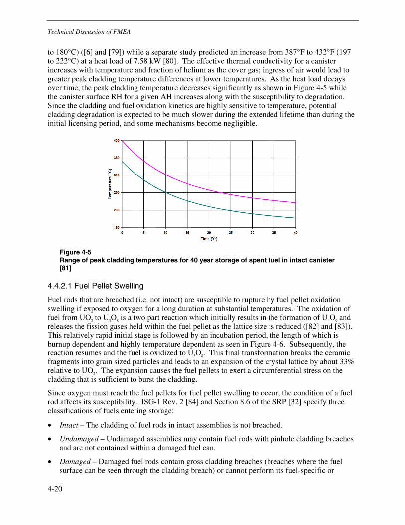
Technical Discussion of FMEA
4-20
to 180°C) ([6] and [79]) while a separate study predicted an increase from 387°F to 432°F (197 to 222°C) at a heat load of 7.58 kW [80]. The effective thermal conductivity for a canister increases with temperature and fraction of helium as the cover gas; ingress of air would lead to greater peak cladding temperature differences at lower temperatures. As the heat load decays over time, the peak cladding temperature decreases significantly as shown in Figure 4-5 while the canister surface RH for a given AH increases along with the susceptibility to degradation. Since the cladding and fuel oxidation kinetics are highly sensitive to temperature, potential cladding degradation is expected to be much slower during the extended lifetime than during the initial licensing period, and some mechanisms become negligible.
Figure 4-5 Range of peak cladding temperatures for 40 year storage of spent fuel in intact canister [81]
4.4.2.1 Fuel Pellet Swelling
Fuel rods that are breached (i.e. not intact) are susceptible to rupture by fuel pellet oxidation swelling if exposed to oxygen for a long duration at substantial temperatures. The oxidation of fuel from UO2 to U3O8 is a two part reaction which initially results in the formation of U4O9 and releases the fission gases held within the fuel pellet as the lattice size is reduced ([82] and [83]). This relatively rapid initial stage is followed by an incubation period, the length of which is burnup dependent and highly temperature dependent as seen in Figure 4-6. Subsequently, the reaction resumes and the fuel is oxidized to U3O8. This final transformation breaks the ceramic fragments into grain sized particles and leads to an expansion of the crystal lattice by about 33% relative to UO2. The expansion causes the fuel pellets to exert a circumferential stress on the cladding that is sufficient to burst the cladding.
Since oxygen must reach the fuel pellets for fuel pellet swelling to occur, the condition of a fuel rod affects its susceptibility. ISG-1 Rev. 2 [84] and Section 8.6 of the SRP [32] specify three classifications of fuels entering storage:
• Intact – The cladding of fuel rods in intact assemblies is not breached.
• Undamaged – Undamaged assemblies may contain fuel rods with pinhole cladding breaches and are not contained within a damaged fuel can.
• Damaged – Damaged fuel rods contain gross cladding breaches (breaches where the fuel surface can be seen through the cladding breach) or cannot perform its fuel-specific or

Technical Discussion of FMEA
4-21
system related functions. Assemblies with damaged fuel rods are confined within damaged fuel cans which have screened openings for draining after transfer and to promote convective cooling.
Fuel rods that are both breached and undamaged have the potential to release fuel particulates into the canister plenum following fuel oxidation and cladding rupture. Damaged fuel rods may also degrade and rupture but are less of a concern because fuel or debris that is released would be confined inside a screened can designed to contain damaged fuel. The size and shape of the initial cladding penetration affects how quickly the fuel oxidizes and how severely the cladding ruptures by limiting the access to oxygen. Initially, only the fuel directly below the original breach oxidizes to U3O8, but a progressive unzipping of the cladding can occur.
For fuel pellet swelling to not be of concern for the length of the interim dry cask storage, the pellets must not be exposed to oxygen until the temperature of the fuel pellets cooled by air remains below 300°F (150°C) for low burnup assemblies and 390°F (200°C) for high burnup fuels [85]. It should be noted that fuel can be exposed to oxidizing conditions at higher temperatures without swelling, if the period of exposure is shortened. Additionally, if the temperature decay over time is considered and specific burnups are known, slightly higher maximum cladding temperatures could be justifiable. NP-4524 [82] cites a higher maximum temperature but assumes that the fuel is loaded at a much cooler peak cladding temperature than industry practice such that the fuel decays more rapidly to lower temperatures.
Figure 4-6 Time from ingress of oxygen into fuel rod to defect propagation in breached cladding due to pellet swelling as a function of temperature and burnup [86]
1E-4
1E-3
1E-2
1E-1
1E+0
1E+1
1E+2
1E+3
1E+4
200220240260280300320340360380400
Tim
e to
Cla
ddin
g R
uptu
re (y
r)
Temperature (°C)
15 GWd/MTHM
30 GWd/MTHM
45 GWd/MTHM
60 GWd/MTHM

Technical Discussion of FMEA
4-22
4.4.2.2 Cladding Oxidation
The oxidation rate of Zircaloy cladding is strongly dependent on temperature and could potentially lead to degradation of both intact and breached fuel rods. SPAR-II [10] indicates that corrosion rates at 400°C in steam are about 70µm/yr. Based on a number of models in Appendix A3.1 of Reference [68], the oxidation rate of Zircaloy is between 5-8 µm/yr at 400°C and is about 1.5-2 µm/yr at 360°C. Because the cladding is only over 360°C for a short time during which canister penetration is very unlikely, breached canisters are unlikely to experience additional cladding breaches over the extended storage period due to cladding oxidation, even in the presence of oxygen.
4.4.2.3 Creep
Creep leading to ductile rupture of the cladding is expected to be the limiting degradation mechanism for fuel rod cladding while in dry storage in an inert atmosphere [87]. Creep is time-dependent plastic deformation which occurs in response to applied or residual stresses. In zirconium alloys, creep is strongly temperature dependent, and decreases as the temperature decreases. Creep in fuel rod cladding occurs as a result of the stresses in the cladding generated by internal pressure in the rod. The internal pressure is a result of two factors: initial pressurization of the fuel rod with helium during manufacture, and release of fission gases from the fuel during power operation. Creep concerns apply to zirconium alloy fuel cladding but, per a study for the NRC, not to stainless steel cladding [77].
Creep is one of the main criteria used to determine cladding temperature limits for dry cask storage. Setting this limit at 752°F (400°C) keeps the total creep for the life of the dry storage to below 1%, well below values that could cause rupture [69]. Two factors that contribute to low cladding strains over the extended storage life are that that (1) creep of the cladding increases the volume of the gas space in the fuel rod thereby reducing the stress levels and decreasing the creep rate and total amount of creep, and (2) the temperature is continuously decreasing, also reducing the rate and total amount of creep ([77] and [34]). For these reasons, creep is typically self-limiting and unlikely to play a significant role in causing rupture of the fuel cladding for canisters whose confinement has not been penetrated.
If confinement failure occurs early in the storage lifetime of a canister and air ingress leads to a significant increase in cladding temperature, additional creep of fuel rods in the hottest central region of the basket may occur. The decay in heat load during the storage interval prior to confinement penetration and the aforementioned self-relieving of stresses mean that creep is still unlikely to be of concern in most cases. It is noted that the temperatures which can lead to fuel oxidation and swelling are expected to be more limiting than those which can lead to creep degradation.
4.4.2.4 Hydrogen-Induced Degradation
Under certain conditions, zirconium alloys have been found to be susceptible to embrittlement and cracking as a result of absorbed hydrogen ([87] and [69]). During power operation, corrosion of the cladding occurs and some of the hydrogen released by the reaction of water with zirconium is absorbed by the cladding. This leads to a gradual increase in the hydrogen concentration as burnup of the fuel continues. The solubility of hydrogen in zirconium alloys is a strong function of temperature and, at low temperature, the solubility becomes very low. The combination of increased levels of dissolved hydrogen in high burnup fuel and the low solubility

Technical Discussion of FMEA
4-23
for hydrogen at low temperature result in possible problems caused by precipitation of the hydrogen as hydrides in the cladding at low temperature. Although hydrogen-induced mechanisms which can cause cladding degradation exist, the temperature increases associated with the loss of the helium cover gas are insufficient to cause deleterious effects as discussed in the following paragraphs, unless the loss of helium occurs at high enough heat loads to exceed existing regulatory temperature limits.
One of the possible conditions generated by precipitation of hydrides is embrittlement of the cladding [69]. The degree of embrittlement is controlled by the orientation and amount of hydrides. The brittle behavior of hydrides is more damaging in the radial orientation because it promotes cracking through-wall. Detailed evaluation of the hydride orientation that can be expected in spent fuel in dry storage casks indicates that the hydrides will mainly be in a circumferential orientation and are unlikely to cause problems during dry storage, even after low temperatures have been reached and most of the hydrogen has been precipitated out as hydrides [34]. However, a report for the NRC [77] concludes that this issue is not completely resolved and that more data should be developed, including for the new cladding alloys. Thus, some uncertainty remains regarding the long term implications of hydrogen-induced embrittlement.
The other possible problem associated with precipitation of hydrides is occurrence of delayed hydride cracking (DHC). This mode of cracking is associated with the attraction of dissolved hydrogen to high stress locations at the tip of a notch or crack, resulting in formation of hydrides at the tip that can then crack if they grow large enough. The stress field at the tip of the new crack can restart the process of hydrogen attraction to the crack tip, resulting in a new region of hydrides and possible crack extension. This process can lead to gradual growth of the crack in a step by step manner, provided that the stress intensity factor is above a threshold value. Testing indicates that the rate of DHC depends on an Arrhenius relation up to about 275°C, then decreases rapidly at higher temperatures [88]. Detailed evaluations by and for EPRI of this mechanism for spent fuel stored in dry cask canisters indicate that it will not be active and is not a concern ([69] and [89]). This is a result of the absence of high stresses or large initiating flaws required to exceed the threshold stress intensity factor for DHC to occur [89]. However, a report prepared for the NRC concludes that it seems possible that a small fraction of fuel rods may experience DHC, but that any resulting cracks in the fuel cladding are expected to be minor and not to lead to gross rupture [89]. Thus, some uncertainty remains regarding the long term possibility of DHC, especially for high burnup fuel.
Hydrogen-induced degradation is mainly a concern in the event of large temperature cycles or if the hydrogen is made more mobile by cladding temperature close to or beyond the regulatory temperature limit. As with creep, the temperatures which can lead to fuel oxidation and swelling are more limiting than those related to hydrogen-induced degradation.
4.4.2.5 Other Cladding Degradation Mechanisms
As the burnup of fuel rods increase, the risks of certain types of in-core degradation increase such as buildup of oxide and crud, which could spall off. The presence of these conditions in high burnup fuel is not guaranteed since fuel and cladding design improvements have been made as planned burnups have increased. The danger of oxide spalling is that a hydride blister could occur as the previously insulated region of cladding cools and hydrogen in the region migrates down the thermal gradient to a localized region where it precipitates [77]. The spalling of crud should be less likely to cause a penetration in cladding than to increase the source term of loose contamination inside the canister and is not expect to occur after dry storage begins [69].
Technical Discussion of FMEA
4-24
Pellet-cladding interaction (PCI) leading to SCC of Zircaloy clad fuel is not credible because the temperature changes required do not produce sufficient cladding stresses (i.e. power ramps during operation) [87].
Annealing of the cladding may reduce its strength, lowering its resistance to creep but improving its resistance to rupture in the event of a mechanical shock [69]. Some annealing of cladding may occur but is very unlikely to cause degradation. Additionally, the safeguards in place for vacuum drying and lack of combustibles to fuel a fire on the ISFSI concrete pad should preclude more complete annealing and greater consequential creep.
4.4.2.6 Consequences and Detectability of Cladding Degradation
The possible consequences of a gross rupture of the cladding for fuel rods outside damaged fuel cans include difficulty in removing fuel from the canister and the release of fission product gases and fuel particulates into the interior of the canister.
In the event of many simultaneous rod ruptures, the fission gas and rod helium backfill release could slightly pressurize the canister and provide a driving means of ejecting particulates through the canister penetration. For less severe rupture events, the fission gases will eventually diffuse out of the canister and particulates are unlikely to be released.
Once the stored fuel cools to a temperature below levels that leads to fuel pellet swelling (about 150-200°C), the risk of cladding rupture is precluded. The third RAI response of the Calvert Cliffs ISFSI license renewal [6] notes that stored fuel in a NUHOMS canister with a thermal load of 4 kW and air as a cover gas has a peak cladding temperature of about 355°F (180°C). Additional evaluations found that decay from maximum loading to a thermal load of 4 kW corresponds to a cooling time on the order of 50 years [90]. Similar time scales are expected for vertical storage configurations.
Various inspection technologies were evaluated by ANL 12/18 [12] for detecting degraded fuel assemblies inside canisters. The techniques evaluated include imaging the canister interior from outside the overpack using collimated gamma-ray detectors and checking for changes in the thermal profile using thermal imaging or other sensors.
4.4.3 Hydrogen Generation and Detonation
Another potential consequence of the ingress of air is the creation of H2 gas as a corrosion byproduct or by radiolysis of water such as moisture in the air. The constant airflow surrounding the canister eliminates the possibility that the hydrogen will accumulate to significant levels outside the canister. Following canister penetration, any hydrogen generated could accumulate to some extent in the interior of the canister but would also partially escape through the penetration. The lower volumetric concentration limit for detonation of hydrogen in air is 18% while the lower flammability limit is 4% [91]. Since diurnal temperature cycles cause continued gas transportation and mixing with the atmosphere, the hydrogen generation rate would need to replenish the hydrogen lost through the canister penetration to maintain a given hydrogen concentration level. Consequently, the volume of water required to generate the required concentration of hydrogen for flammability is not only larger than the instantaneous moles of hydrogen required, it also increases with air leak rate. As the gas exchange rate through the canister penetration increases (particularly for cracks near the top of the canister), the equilibrium hydrogen concentration will decrease.
Technical Discussion of FMEA
4-25
Aqueous corrosion of zirconium or aluminum is the only possible corrosion source of H2 following canister penetration. Generation of hydrogen by radiolysis of water is possible at limited rates, but both of these mechanisms are unlikely to lead to explosive conditions due to the limited quantity of water in the canister (e.g., humid air and rain ingress) and the daily ingress of ambient air from thermal cycling. The rate of hydrogen generation is expected to be much lower than during loading operations [24] because the volume of water inside the canister is very limited. Reference [68] determines that the time constant for the radiolytic decomposition of water inside a sealed dry canister is between 4.8 and 72 years. Similarly, the oxidation of reactive metals by water is competing against the oxidation of the metals by air which will tend to decrease hydrogen generation rates relative to corrosion in pure steam.
Limited operating experience with a cask known to be slowly leaking has found that hydrogen reached equilibrium at concentrations below concern for ignition. Data from gas samples inside the leaking REA-2023 cask over the two years following the development of a leak in a fitting show the hydrogen leveled off at a concentration of 0.47% by volume [72]. It is noted that the cask contains low decay heat (less than 1 kW) damaged fuel and that freezing temperatures were reported inside the cask during winter. Each of these factors would likely lead to lower hydrogen generation rates due to reaction rate kinetics. The fitting was subsequently tightened and the hydrogen concentration decreased. This concentration remained significantly lower than the flammability limit.
The likelihood of hydrogen detonation is very low because 1) operating experience indicates the rate of hydrogen production is likely insufficient to reach flammable concentrations, let alone explosive concentrations, and 2) there is no source of ignition inside the overpack. If detonation were to occur inside the canister, it could cause the cladding surface temperature to increase for a very short period of time, increase the crack opening area, and potentially release particulates into the atmosphere. Hydrogen ignition can occur at lower hydrogen concentrations, but would be less likely to expand the flaw or release material from the interior.
4.4.4 Degradation of Fuel Basket
In the event of a through-wall penetration of the canister, ingress of oxygen and humidity or rainwater into the canister could then lead to exposure of the aluminum and carbon steel used in some fuel basket designs to conditions that support galvanic or general corrosion.
For aluminum basket designs, galvanic corrosion in the atmosphere would be minimal since borated aluminum and stainless steel have been used in spent fuel pools for over 30 years with no reported degradation by galvanic corrosion [20]. General corrosion of the carbon steel spacer and support plates used in some basket designs would not be expected to occur due to the low humidity expected inside the hotter interior of the canister, absent intrusion of liquid water. Degradation of the internals by CISCC is very unlikely for a small penetration due to the time it would take for chlorides to accumulate to significant concentrations inside. The amount of chloride that could be carried in as a deliquescent brine is insufficient to cause significant structural damage to more than a local area near the penetration. However, a flooding event at a marine site could provide both the moisture and chlorides to eventually cause significant corrosion of canister internals if it causes flooding of the canister.
A relatively small creep of aluminum baskets during storage of high heat-load fuels has also been mentioned as a concern because the relatively tight tolerances required for the insertion and removal of fuel assemblies means binding could occur [77]. This concern is heightened by the

Technical Discussion of FMEA
4-26
additional time at elevated temperatures for breached canisters and the possibility of blisters on Boral neutron poison plates.
Degradation of the fuel basket could impair the removal of fuel assemblies from the canister. Substantial degradation could also compromise the function of basket support plates in the event of a canister drop, leading to additional stresses on fuel assemblies and an increased probability of rupture. A method for detecting fuel basket degradation is not currently available. However, the very minimal expected frequency of occurrence and the significant time required for conditions aggressive to the basket to develop inside the canister substantially reduce the importance of this potential effect.
4.4.5 Potential for Criticality
In the very unlikely event that liquid water were to enter the canister in quantities sufficient to submerge a large portion of the fuel assemblies, it would increase the spent fuel reactivity as a result of its neutron moderation properties. In a given DCSS canister, the changes that could increase the reactivity are as follows:
• Ingress of moderator (e.g., due to a flood, storm surge, or many years of rain ingress)
• Change in fuel geometry (e.g., rupture of many fuel rods leading to loose piles of fuel pellets)
• Reduction of neutron poison effectiveness
The criticality analyses within FSARs evaluate the changes in keff due to external flooding, filling the canister with varying densities or levels of moderator, and slight changes in fuel spacing with the fuel cells ([24], [13], [19], and [25]). A report by ORNL [92] stated that the specific changes in fuel geometry required to lead to significant criticality increases, such as those presented in NUREG/CR-6835 [93], are not credible for fuel in storage. EPRI 1015050 [94] also demonstrates there is no credible mechanistic pathway to lead to criticality, even considering the greater loads of transportation accidents. The close spacing of fuel pellets in a heap, a conceivable reconfiguration after severe degradation of fuel rods, reduces the reactivity due to the undermoderated geometry. The optimal spacing of loose fuel pellets requires them to be suspended in moderator (snow globe effect), which could only happen temporarily due to sloshing of water in a partially flooded canister. However, the partial flooding would provide a smaller reactivity increase than full flooding. Optimal moderation of the fuel rods by expanding the lattice spacing within basket cells also does not increase reactivity past the administrative margin of 0.05. Consequently, there is not a credible change in fuel geometry which could lead to criticality in storage conditions. A recent joint ORNL and NRC paper [71] based partially on the ORNL report did not fully dismiss criticality in all SNF scenarios (i.e. storage and transport).
Concerns that degradation of neutron poison panels, such as blistering of Boral panels or Boron-10 depletion, could significantly reduce the attenuation effectiveness of the panels are not credible. The blistering of Boral panels as a result of the boiling of water absorbed into the ceramic matrix core during loading in the spent fuel pool does not affect the efficacy of the neutron poison and would not cause a significant change in geometry. The reduction in attenuation due to neutron absorption is not significant given the calculated fluence over an assumed extended canister lifetime of 120 years ([78] and [95]).
Therefore, a credible scenario resulting in a critical configuration of spent fuel does not exist for the conditions applicable to DCSS storage.

5-1
5 IMPLICATIONS OF THE FMEA
This section discusses the findings of the FMEA in the context of aging management concerns. The most likely causes and consequences of confinement penetration are considered along with the potential for mitigation and detection of these concerns.
5.1 Most Likely Cause of Confinement Penetration
The most likely failure mode for the confinement boundary at marine sites is expected to be through-wall cracking by chloride-induced stress corrosion cracking. At ISFSIs without a significant source of chlorides, other mechanisms may also warrant consideration as sources of degradation, but these sites are expected to have a much lower overall susceptibility to degradation when compared to marine sites with significant chloride deposits on canister shells.
Based on the information gathered for the FMEA, the most likely morphology of and locations for occurrence of CISCC on canisters can be hypothesized. The WRS profile indicates that a through-wall crack is most likely to occur transverse to the weld bead, leading to a relatively short crack. High chloride concentrations are more likely to occur on the upward facing surfaces of canisters due to gravitational settling. In the event of rainwater intrusion, which was indicated in small quantities by images in the Calvert Cliffs inspection, chlorides and water may also be transported into the region along the horizontal canister support rail. The region under the baseplate is of greatest concern for the horizontal canisters. The crevice environment under the baseplate is expected to be of less concern because of the thicker adjoining material and ability for water to drain away. The temperature profiles presented in the DCSS FSARs indicate that the ends and underside of horizontal canisters are the locations with the lowest temperature, where the local RH is highest and will support deliquescence the earliest. For the vertical canisters, the bottom lid and the bottom of the shell are the coolest. As the canister heat load decays, the areas potentially susceptible to deliquescence will expand, and the top lid of vertical canisters will become susceptible. The shell and associated welds are judged to be of greater susceptibility than the canister lids since the lids are 3-18 times thicker than the shell and typically have redundancy in areas with significant tensile residual stresses.
For canisters at marine sites, the locations expected to have a combination of the lowest temperatures and the highest chloride deposition rates are expected to be at greatest risk for degradation. Penetration of the top structural lid, enclosure ring, or the associated welds also requires sequential penetration of a second component to lead to a loss of confinement. Consequently, the locations of greatest likelihood for cracking on horizontal canisters are the regions of high tensile residual stress near the welds at the end of the shell, in particular those which are on the upward facing side or in contact with the support rail. The location of greatest likelihood for through-wall cracking on vertical canisters is the high residual stress region around the shell-to-bottom lid weld, particularly the areas near air inlets. Table 5-1 summarizes the locations germane to CISCC susceptibility factors.

Implications of the FMEA
5-2
One means of evaluating the possibility of CISCC degradation may be to monitor the canister environment to see whether the chloride concentration and RH are at values that have led to CISCC in tests of analogous specimens. The short (matter of weeks) initiation times seen in most CISCC laboratory testing means that, from an aging management perspective, it may be appropriate to assume that crack initiation has occurred once surface conditions support deliquescence and the chloride deposit concentration passes a threshold.
For ISFSIs where the canisters will not experience surface chloride concentrations near the CISCC susceptibility threshold during extended storage, the material degradation mechanism or mechanisms that are most likely to lead to confinement penetration are not obvious given current information. Nevertheless, non-marine ISFSIs are expected to be much less susceptible to material degradation than marine sites.
Table 5-1 Most Likely Locations for CISCC Degradation
Factor for CISCC Susceptibility Locations on Horizontal Canister Locations on Vertical Canister
Tensile Stresses on OD Regions in the vicinity of welds (e.g. within about 2 thicknesses)
Regions in the vicinity of welds (e.g. within about 2 thicknesses)
Low Surface Temperature(1)
Lids; shell along canister underside and lids
Outside of bottom lid and lower part of shell
High Chloride Deposition Top of canister shell Top lid; to a lesser extent, vertical areas in the vicinity of the overpack inlets
Crevice Environment Support rail contact region Under baseplate
Material Condition Areas of grinding or mechanical abuse (e.g. gouges)
Areas of grinding or mechanical abuse (e.g. gouges)
Most Susceptible Location(s)
Shell welds at canister ends (top surface); support rail interface near welds
Canister sides near welds at the bottom of the canister
Notes: 1. Low surface temperatures may lead to aqueous conditions due to deliquescence at high local humidities.
However, higher surface temperatures are likely to cause reduced time to CISCC initiation and higher CISCC propagation rates since CISCC is a thermally activated corrosion mechanism. While deliquescence is a threshold type limiting mechanism, the thermal activation of corrosion is a continuous effect such that fastest propagation would tend to occur on surfaces that are just cool enough to sustain deliquescent brine.
5.2 Most Likely Consequences of Confinement Penetration
Subsequent to a hypothetical penetration of canister confinement (and conditional on this relatively unlikely event occurring), any helium backfill overpressure would be relieved and air would gradually replace helium as the cover gas. If fuel assemblies are breached, some fission gases would be released with the helium backfill. The timescale of this process would determine whether any particulate contamination would be released, with higher gas flow rates more likely to entrain particles of crud that could have settled on a surface near the penetration. However, in the most likely case that the penetration is a tight crack, the flow path would likely prevent the release of particulates from the canister to the environment.

Implications of the FMEA
5-3
Once exposed to oxidizing conditions, the consequences to the fuel assemblies depend on the integrity of the fuel cladding and the new temperature resulting from the replacement of helium with air. For cladding temperatures relevant to dry storage, no new cladding breaches would be expected as a result of cladding oxidation. For any fuel rods which are breached and not in damaged fuel cans, fuel temperatures below 300°F (150°C) for low burnup fuel and 390°F (200°C) for high burnup fuel would preclude cladding ruptures due to fuel pellet oxidation swelling for the extended canister life. Higher fuel temperatures could be tolerated without risk of rupture of breached rods if the potential period of fuel oxidation was shorter than the full period of extended storage, which could apply in the case of periodic inspections or monitoring for confinement integrity. The lack of a substantial pressure gradient with the outside during and following the ingress of air means that any fuel assembly degradation would be unlikely to cause a substantial release of radioactivity.
5.3 Limiting Conditions and Potential for Mitigation
Considering the cut sets of the fault tree in Figure 3-3, the common parameters which lead to the highest likelihood of failure are the presence of aqueous conditions at the canister surface and the presence of chlorides. Additional parameters of importance include residual stresses and crevice geometries, but these are not as amenable to mitigation for in-service canisters due to the need to remove the canister from the overpack to perform stress improvement or modify the overpack geometry, respectively.
EPRI 1011820 Appendix B [96] includes a summary of stress mitigation technologies that could be applied to welded dry cask storage canisters to reduce their susceptibility to SCC in marine environments. For example, recent CRIEPI tests of surface stress mitigation using low plasticity burnishing and shot peening [97] showed no SCC initiation under conditions that led to initiation in the unmitigated sections of weld. Improving surface finishes could also eliminate microcrevices and reduce the deposition rate of aerosols on the canister, particularly for vertical surfaces.
Sections 5.3.1 and 5.3.2 further discuss the degradation mitigation for the canisters currently in service.
5.3.1 Aqueous Conditions
A prerequisite for the degradation mechanisms listed in Section 4.2 is to have wetted conditions on the metal surface. The primary means for this to occur on the surface of a canister are: deliquescence, ingress of rainwater or fog, and dripping of water through cracks in concrete. Potential methods for limiting aqueous conditions could involve adding louvers or covers to the outlets to reduce the chances of rain ingress.
For degradation analysis purposes, a lower maximum AH and the periodic efflorescence and deliquescence associated with variations in ambient temperature and humidity could provide opportunities to take site-specific credit for limited active degradation time. This effect would be most beneficial if the daily maximum humidity remains low for the majority of the year. Frequent drying and rewetting could be detrimental because it exposes the surface to the highest concentration brine for a significant portion of the duty cycle.

Implications of the FMEA
5-4
5.3.2 Chloride Loading
For canisters where the chloride surface loading is shown to be below the initiation threshold, another option would be to limit the subsequent rate of chloride deposition in order to maintain the deposited chloride concentration below the initiation threshold. CRIEPI has experimented with adding a filter to overpack inlets [48] with some success at reducing chloride ingress rates without affecting decay heat removal.
Cleaning of the canister surfaces, such as by flushing with pressurized demineralized water, may be another option if the potential for transport of chlorides into crevices is addressed.
5.4 Potential for In-Situ Degradation Detection
For radiological dose and economic purposes, any monitoring for canister degradation would be best done in-situ and without opening the overpack. The detectability of degradation mechanisms is hampered by the conditions of canister storage. The tight annulus and heat conduction channels in some vertical designs reduce the area that can be easily accessed via the inlets and outlets. In the event that part-depth flaw detection of the full canister surface becomes necessary, the access limitations would complicate volumetric or surface examinations and likely necessitate removal of the canister from the overpack with temporary shielding. Monitoring of canisters for the acoustic signature of cracking may prove feasible in the future, but the technology is not currently field-ready [12]. Potential methods of indirectly determining confinement integrity are as follows:
• Determine the temperature difference between the canister top and bottom, and compare with baseline measurements, models using air as the canister internal gas, and models using pressurized and ambient pressure helium as the canister internal gas [12]. The degraded heat transfer performance associated with lower pressure helium or air as a cover gas leads to a decreased temperature gradient along the sides of the canister, although the average surface temperature remains roughly the same because the decay heat is unchanged by the cover gas properties. It is noted that Reference [12] indicates that an increased temperature difference is expected as helium cover gas is lost, but the referenced experiment [98] compared temperatures at the centers of the top and bottom lids of vertical canisters, which would not be a practical measurement to obtain. The temperature difference from the bottom to the top of the canister shell decreases by a smaller magnitude. The analysis of Reference [80] demonstrates that there is also a decreased temperature difference for horizontal canister designs between the top and side of the canister which is most pronounced at the axial midpoint.
• Determine the speed of sound of the gas within the canister [12]. The speed of sound varies with square root of the change in the adiabatic index and in the inverse of the molar mass as helium is replaced by air, which leads to a factor of 2.9 difference between canisters backfilled with ambient pressure helium vs. air. This factor would be reduced by the initial presence of fission gases from any breached fuel rods.
• Monitor the outlet gas. An Idaho National Laboratory report indicates that it may be possible, depending on leak rate, to detect helium leaking from the canister in the outlet air stream [12]. An alternative could be to sample the outlet airflow for the presence of radioactive fission gasses.

Implications of the FMEA
5-5
There is also a continued effort to evaluate the feasibility of performing direct non-destructive examination (NDE) inspections of stored canisters using ultrasonic testing (UT) and eddy current testing (ET) techniques ([99] and [100]). The first study considers the NDE and probe types that would be best suited to use on canisters. The second study showed that the accessibility of the canister surface is strongly dependent on the specific design of the overpack and indicates that cleaning of the canister surface in areas with dust or other surface deposits may be necessary to achieve adequate coupling of the transducers with the surface.


6-1
6 CONCLUSIONS AND FUTURE WORK
6.1 Conclusions
The FMEA process was used to investigate the potential failure modes of the welded stainless steel canisters used as the confinement boundary for the HI-STORM, NUHOMS, NAC UMS/MPC/MAGNASTOR, and FuelSolutions series of dry cask storage systems. In general, the susceptibility of various designs to degradation was considered by grouping the horizontal canisters (NUHOMS series) and the vertical canisters (all others). Within this scope, the effort was divided into two segments: determining failure modes and mechanisms for the confinement boundary, and determining the effects of confinement penetration with consideration of the likelihood of each degradation mechanism. In Sections 3.2.2 and 4.2, this FMEA identified several material degradation mechanisms that could potentially affect canister integrity:
• Chloride-induced stress corrosion cracking (CISCC)
• Pitting corrosion
• Crevice corrosion
• Microbiologically induced corrosion (MIC)
• Intergranular attack (IGA)
Of the degradation mechanisms, CISCC is concluded to be of greatest potential concern for causing penetration of the confinement boundary. The susceptibility of canisters to degradation at ISFSIs in marine environments, where there is significant concentration of chloride aerosols, is greater than at non-marine ISFSIs due to the lower likelihood that aggressive species would accumulate on those canisters to levels that could lead to degradation. The rapid inland decay in chloride concentration and deposition rates may also limit marine environments to those proximal to marine water with breaking waves. Since deliquescence or the ingress of water is required for any of the material degradation mechanisms to be active (i.e. the low cyclic loading during storage is not sufficient to cause flaw initiation by fatigue in the canister wall), a given area of the canister surface is expected to be not susceptible to degradation and through-wall penetration until the temperature cools to a relatively low temperature (e.g. at least below 140°F/60°C).
As discussed in Section 5.1, the location of greatest concern for the vertical canister is the region of the shell along the circumferential shell-to-bottom lid weld. The regions of greatest concern for the horizontal canisters include the shell along the support rail and the top of the shell near the shield plugs and lids. Within these regions, the areas near a weld (within about two thicknesses) are the most susceptible areas due to tensile residual stress and material condition.
The various failure modes considered in Sections 3.2.1 and 4.3 all result in through-wall penetration of the confinement boundary but differ in the size of the penetration. The smallest and most probable, a crack-like penetration, is likely to be sufficiently tight to preclude the

Conclusions and Future Work
6-2
release of particulates as the inert cover gas and any accumulated fission gases escape and air enters over many weeks or years. It is expected that the degradation would take the form of short cracks growing through-wall with an orientation perpendicular to the nearest weld. Although substantially less likely, a gross penetration where some of the bulk material has been removed, for example due to pitting or IGA, could release some loose particulates from the canister, and the release would occur over a shorter time period. For a large crack opening area such as a canister rupture, the immediate release of material could include fuel particles. This failure mode is very unlikely because of the large flaw sizes required for rupture, even under accident loading. In addition, there is a high likelihood that wall penetration would occur at some point along a long part-depth flaw, removing the driving force for rupture.
As noted in Sections 3.2.3 and 4.4, the immediate to short-term consequences of canister degradation are the release of any accumulated fission gases and the helium backfill from the canister interior. Particles of crud, or possibly fuel debris in the case of a rupture due to an accident event, also have the potential to be released. Without the inert atmosphere, cladding degradation may occur by the mechanisms described in Section 4.4.2, plausibly generating more contaminated debris in the canister that could be released during handling or any future accident events. After a long enough cooling time, the lower temperature will reduce the rod plenum pressure and oxidation kinetics to the point where additional cladding degradation is very unlikely.
The common characteristics of the aging degradation related failure modes identified in this FMEA could be effectively detected or mitigated by indirect means proposed in Sections 5.3 and 5.4. The degradation chain begins with the accumulation of aggressive species on the canister surface which then can lead to the formation of deliquescent brines at high ambient humidities once the canister surface temperature is low enough. Prevention of either deposition of aggressive species or development of aqueous conditions at the canister surface would greatly reduce the potential for material degradation. As another approach, monitoring the chloride surface loading would provide reasonable assurance of canister integrity. Monitoring the properties of the cover gas could provide means for detecting confinement failure after conditions that support material degradation have developed but prior to the potential for significant degradation of cladding.
6.2 Future Work
This FMEA is part of an effort to develop an industry Aging Management Plan that will address potential canister degradation concerns due to materials aging effects. The FMEA does not include quantitative assessments of the time required by each of these degradation mechanisms to cause confinement penetration. The following tasks are planned to complete this effort, focusing on the completion of flaw growth and flaw tolerance modeling, review of available field data, and development of susceptibility assessment criteria:
• Literature Review - Mid 2014. This technical update will document the literature review on chloride induced degradation.
• Flaw Growth and Flaw Tolerance Assessment - Late 2014. This assessment will document flaw growth and flaw tolerance calculations that consider the development of environmental conditions affecting initiation and growth, including aerosol deposition, residual stress, and deliquescence.

Conclusions and Future Work
6-3
• Industry Susceptibility Assessment Criteria – Mid 2015. This report will develop a set of criteria by which licensees can determine the susceptibility of their stored canisters to materials aging degradation.
• Stainless Steel Canister Confinement Integrity Assessment – Late 2015. This report will include further development of the models from the Flaw Growth and Flaw Tolerance Assessment into a probabilistic framework.
• Aging Management Plan Guidance – Early 2016. This report will provide recommendations on items to inspect, inspection intervals, inspection and monitoring technologies, and flaw evaluation and acceptance criteria as well as potential mitigation techniques that may be used to reduce the need for monitoring.

7-1
7 REFERENCES
1. Industry Spent Fuel Storage Handbook, EPRI, Palo Alto, CA: 2010. 1021048.
2. NRC Information Notice IN 2012-20, “Potential Chloride-Induced Stress Corrosion Cracking of Austenitic Stainless Steel and Maintenance of Dry Cask Storage System Canisters.”
3. L. Caseres and T. S. Mintz, NUREG/CR-7030, “Atmospheric Stress Corrosion Cracking Susceptibility of Welded and Unwelded 304, 304L, and 316L Austenitic Stainless Steels Commonly Used for Dry Cask Storage Containers Exposed to Marine Environments,” U.S. Nuclear Regulatory Commission, Washington DC, 2010.
4. G. Oberson, D. Dunn, T. Mintz, et al., “US NRC-Sponsored Research on Stress Corrosion Cracking Susceptibility of Dry Storage Canister Materials in Marine Environments,” WM2013 Conference, 2013. (Available with NRC Accession No. ML13029A490)
5. Letter from G. H. Gellrich to J. Goshen, “Response to Request for Supplemental Information, RE: Calvert Cliffs Independent Spent Fuel Storage Installation License Renewal Application (TAC No- L24475),” July 27, 2012. (Available with NRC Accession No. ML12212A216)
6. Letter from M. D. Flaherty to Document Control Desk, “Response to Request for Additional Information, RE: Calvert Cliffs Independent Spent Fuel Storage Installation License Renewal Application (TAC No. L24475),” June 14, 2013. (Available with NRC Accession No. ML13170A574)
7. O. K. Chopra, D. Diercks, R. Fabian, D. Ma, V. Shah, S.-W. Tam, and Y. Y. Liu, Managing Aging Effects on Dry Cask Storage Systems for Extended Long-Term Storage and Transportation of Used Fuel, Revision 1, Argonne National Laboratory, ANL-13/15, 2013. (Available at http://www.ipd.anl.gov/anlpubs/2013/10/77650.pdf)
8. IAEA, Operation and Maintenance of Spent Fuel Storage and Transportation Casks/Containers, IAEA-TECDOC-1532, January 2007.
9. Extended Storage Collaboration Program International Subcommittee Report: International Perspectives on Technical Data Gaps Associated With Extended Storage and Transportation of Used Nuclear Fuel. EPRI, Palo Alto, CA: 2012. 1026481.
10. IAEA, Spent Fuel Performance Assessment and Research: Final Report of a Coordinated Research Project (SPAR-II), IAEA-TECDOC-1680, 2012.
11. F. Takáts, “Trend of SFM and Storage in Central and Eastern Europe,” Presentation at IAEA TM-45455 Meeting, July 3, 2013.
12. NRC Job Code V6060: Extended In‐Situ and Real Time Monitoring Task 3: Long‐Term Dry Cask Storage of Spent Nuclear Fuel, Argonne National Laboratory, Nuclear Engineering Division, ANL/NE-12/18, 2012. (Available with NRC Accession No. ML13015A321)
13. Holtec International Final Safety Analysis Report for the HI-STORM 100 Cask System, Holtec International, Rev. 9, 2010. (Available with NRC Accession No. ML101400161)
References
7-2
14. Topical Report for the NuTech Horizontal Modular Storage System for Irradiated Nuclear Fuel NUHOMS®-24P, Pacific Nuclear Fuel Services, NUH-002, Rev. 2A, 1991. (Available with NRC Accession No. ML110730769)
15. Final Safety Analysis Report for the Standardized NUHOMS Horizontal Modular Storage System for Irradiated Nuclear Fuel, Transnuclear West Inc., NUH-003, Rev. 6, 2001. (Available with NRC Accession No. ML020300159)
16. Final Safety Analysis Report for the Standardized NUHOMS Horizontal Modular Storage System for Irradiated Nuclear Fuel, Transnuclear Inc., NUH-003.0103, Rev. 8, 2004. (Available with NRC Accession No. ML042110421)
17. Final Safety Analysis Report for the Standardized NUHOMS Horizontal Modular Storage System for Irradiated Nuclear Fuel, Transnuclear Inc., NUH-003.0103, Rev. 10, 2008. (Available with NRC Accession No. ML080390185)
18. Final Safety Analysis Report Standardized Advanced NUHOMS Horizontal Modular Storage System For Irradiated Nuclear Fuel, Transnuclear, ANUH-01.0150, Rev. 0, 2003. (Available with NRC Accession Nos. ML050410252, ML031040379, ML031040312)
19. NUHOMS HD Horizontal Modular Storage System For Irradiated Nuclear Fuel SAFETY ANALYSIS REPORT, Transnuclear, Rev. 0, 2004. (Available with NRC Accession Nos. ML041540170, ML060440311, ML041540165, ML060440312)
20. Final Safety Analysis Report on the HI-STORM FW System, Holtec International, Rev. 0, 2011. (Available with NRC Accession No. ML112700139)
21. Final Safety Analysis Report on the HI-STORM UMAX System, Holtec International, Rev. 1, 2012. (Available with NRC Accession No. ML12363A282)
22. NAC-MPC Final Safety Analysis Report (FSAR), Revision 9, NAC International, 2012. (NRC accession number ML121070570)
23. NAC-UMS Universal MPC System Final Safety Analysis Report (FSAR), Revision 3, NAC International, 2004. (Available with NRC Accession Nos. ML051290397, ML041040369, ML051290403, ML041040397)
24. MAGNASTOR (Modular Advanced Generation Nuclear All-purpose STORage) Safety Analysis Report, NAC International, Rev. 2, 2008. (Available with NRC Accession Nos. ML083170473, ML081710155)
25. FuelSolutions™ Storage System Final Safety Analysis Report, Rev. 2, BNFL Fuel Solutions Co., 2005. (Available with NRC Accession No. ML060520446)
26. FuelSolutions™ W74 Canister Storage Final Safety Analysis Report, Rev. 4, BNFL Fuel Solutions Co., 2005. (Available with NRC Accession No. ML060520474)
27. Materials Reliability Program: Assessment of the Current Status and Completeness of Work on Inner and Outer Diameter Stress Corrosion Cracking of Austenitic Stainless Steels in PWR Plants (MRP-352), EPRI, Palo Alto, CA: 2013. 3002000135.
28. R. Hosler, Screening Criteria for ID and OD-Initiated SCC of Pressure Boundary Stainless Steel Components (Phase 1 of I&E Guideline Development), AREVA 51-9142337-000, 2010.

References
7-3
29. F. King, Corrosion Resistance of Austenitic and Duplex Stainless Steels in Environments Related to UK Geological Disposal: A Report to NDA RWMD, Ver. 1.2, QRS-1384C-R1, 2009. (Available at http://www.nda.gov.uk/documents/biblio/upload/Corrosion-resistance-of-austenitic-and-duplex-stainless-steels-in-environments-related-to-UK-geological-disposal.pdf)
30. D. H. Stamatis, Failure Mode and Effect Analysis: FMEA from Theory to Execution, ASQ Quality Press, Milwaukee, 1995.
31. U.S. Nuclear Regulatory Commission, “Standard Review Plan for Renewal of Spent Fuel Dry Cask Storage System Licenses and Certificates of Compliance,” NUREG-1927, Washington DC, March 2011.
32. U.S. Nuclear Regulatory Commission, “Standard Review Plan for Dry Cask Storage Systems,” NUREG-1536, Rev. 1, Washington DC, July 2010.
33. Nuclear Energy Institute, Methodology for Development of Emergency Action Levels, NEI 99-01 Rev. 5, February 2008.
34. Spent Fuel Transportation Applications—Assessment of Cladding Performance: A Synthesis Report. EPRI, Palo Alto, CA: 2007. 1015048.
35. M. Stamatelatos and J. Caraballo, “Fault Tree Handbook with Aerospace Applications,” Ver. 1.1, NASA Office of Safety and Mission Assurance, August 2002.
36. U.S. Nuclear Regulatory Commission, “Fault Tree Handbook,” NUREG-0492, Washington DC, January 1981.
37. R. H. Jones, Stress-Corrosion Cracking, Materials Park, OH: ASM International, 1992.
38. R. H. Jones, “Stress-Corrosion Cracking,” ASM Handbook Vol. 13A. Corrosion: Fundamentals, Testing, and Protection. Materials Park, Ohio: ASM International. pp. 346-365, 2003.
39. Workshop Proceedings: Quantitative Micro-Nano (QMN-1) Approach to Predicting SCC of Fe-Cr-Ni Alloys, Sun Valley Resort, June 13-18, 2010.
40. Workshop Proceedings: Quantitative Micro-Nano (QMN-2) Approach to Predicting SCC of Fe-Cr-Ni Alloys – Initiation of SCC, Sun Valley Resort, June 12-17, 2011.
41. Workshop Proceedings: Quantitative Micro-Nano (QMN-3) Approach to Predicting SCC of Fe-Cr-Ni Alloys – Incubation of SCC, Idaho Falls, June 10-15, 2012.
42. Y. Toshima, et al., “Long-Term Exposure Test for External Stress Corrosion Cracking on Austenitic Stainless Steels in Coastal Areas,” CORROSION 2000, Paper No. 00456, NACE, 2000.
43. R. Hosler and J. Hall, “Outside Diameter Initiated Stress Corrosion Cracking Revised Final White Paper,” PWROG document PA-MSC-0474, October 13, 2010. (Available with NRC Accession No. ML110400241)
44. E.R. Lewis, G. de Leeuw, et al., “Production Flux Of Sea Spray Aerosol,” Reviews of Geophysics, Vol. 49, RG2001, May 2011.
45. G. R. Meira, “Modeling Sea-Salt Transport and Deposition in Marine Atmosphere Zone – A Tool for Corrosion Studies,” Corrosion Science, Vol. 50, No. 9, p. 2724–2731, 2008.
References
7-4
46. A. L. Williams and G. J. Stensland, “Atmospheric Dispersion Study of Deicing Salt Applied to Roads: Part II Final Report for Period July 2002 to June 2004,” Illinois State Water Survey Atmospheric Environment Section, FHWA/IL/HRC.2006-1, Champaign, Illinois, 2000. (Available at http://www.dot.state.il.us/materials/research/pdf/prr149.pdf)
47. R. N. Meroney, “CFD Prediction of Cooling Tower Draft,” Fort Collins, Colorado, 2005. (Available at http://www.engr.colostate.edu/~meroney/projects/CFD_Prediction_of_Cooling_Tower_Drift.pdf)
48. M. Wataru, et al., “Sea Salt Deposition on the Canister Surface of Concrete Cask,” ISSF2010, Presentation, November 16, 2010. (Available at http://www.denken.or.jp/result/event/seminar/2010/issf/pdf/5-2_powerpoint.pdf)
49. G. Oberson, “Stress Corrosion Cracking of Spent Nuclear Fuel Dry Storage Canisters,” Meeting with Fuel Cycle and Materials Administration, September 16-19 2013. (Available with NRC Accession No. ML13241A391)
50. M. Wataru, T. Saegusa, Evaluation of the salt deposition on the canister surface of concrete cask – Measurement test of the salt deposition in the laboratory and the field, CRIEPI, N09023, May 2010. (In Japanese)
51. S. Shoji and N. Ohnaka, “Effects of Relative Humidity and Chloride Type on Stainless-Steel Room-Temperature Atmospheric Corrosion Cracking,” Corrosion Engineering, Vol. 38, p. 111-119, 1989.
52. Climatic Corrosion Considerations for Independent Spent Fuel Storage Installations in Marine Environments, EPRI, Palo Alto, CA: 2006. 1013524.
53. C. Bryan, Analysis of Dust Deliquescence for FEP Screening, Bechtel SAIC Co., ANL-EBS-MD-000074, Rev. 01, 2005.
54. T. Ahn, G. Oberson, and S. DePaula, “Chloride-Induced Stress Corrosion Cracking of Austenitic Stainless Steel Used for Dry Storage of Spent Nuclear Fuel,” ECS Transactions Vol. 50, Issue 31, 211-226, 2013.
55. A. Kosaki, “Evaluation Method of Corrosion Lifetime of Conventional Stainless Steel Canister under Oceanic Air Environment,” Nuclear Engineering and Design, Vol. 238, No. 5, p. 1233–1240. 2008.
56. S. DePaula and G. Oberson, “Regulatory Issue Resolution Protocol (RIRP) Pilot: Marine Atmosphere Stress Corrosion Cracking (SCC),” U.S. NRC, April 12, 2012.
57. E. A. Baker and W. W. Kirk, “Long-Term Atmospheric Corrosion Behavior of Various Grades of Stainless Steel in Rural, Industrial, and Marine Environments,” Corrosion Testing and Evaluation: Silver Anniversary Volume, ASTM STP 1000, R. Baboian and S. W. Dean, Eds., American Society for Testing and Materials, Philadelphia, 1990, pp. 177-190.
58. A. Cook, J. Morrow, et al., “Atmospheric-Induced Stress Corrosion Cracking Of Austenitic Stainless Steels Under Limited Chloride Supply,” International Corrosion Council, November 2011. (Available at http://www.academia.edu/2069581/)
59. J. Grubb, T. DeBold, and J. Fritz, “Corrosion of Wrought Stainless Steels,” ASM Handbook Vol. 13B. Corrosion: Materials. Materials Park, Ohio: ASM International. pp. 55-77, 2005.
References
7-5
60. M. Yajima and M. Arii, “Chloride Stress Corrosion Cracking of AISI 304 Stainless Steel in Air,” Materials Performance, Vol. 19, No. 10, p. 17-19, December 1980.
61. R. G. Kelly , “Crevice Corrosion,” ASM Handbook Vol. 13A. Corrosion: Fundamentals, Testing, and Protection. Materials Park, Ohio: ASM International. pp. 242-247, 2003.
62. R. M. Kain, “Crevice Corrosion Behavior of Stainless Steel in Seawater and Related Environments,” CORROSION 1984, Vol. 40, No. 6, NACE, 1984.
63. G. Geesey, A Review of the Potential for Microbially Influenced Corrosion of High-Level Waste Containers, CNWRA 93-014, June 1993. (Available with NRC Accession No. ML040230184)
64. B. Little, R. Ray, and J. Lee, “An Overview of Microbiologically Influenced Corrosion in Aircraft,” NRL/PP/7303/02/0008, 2003. (Available at http://www.dtic.mil/cgi-bin/GetTRDoc?AD=ADA413907)
65. U.S. Department of Energy, Office of Civilian Radioactive Waste Management (OCRWM), Design Calculation 800-K0C-TEG0-01200-000-00A, ECN-001, Rev 00A, “Longevity of Emplacement Drift Ground Support Materials for LA.” (Available with NRC Accession No. ML090690326)
66. X. He, R. Pabalan, T. Mintz, G. Oberson, D. Dunn, and T. Ahn, “Scoping Study of Effect of Salts in Non-Coastal Particulate Matter on Stress Corrosion Cracking of Type 304 Stainless Steel,” CORROSION 2013, NACE, 2013. (Available with NRC Accession No. ML13018A120)
67. C. J. Donohoe, “The Effect of Ionising Radiation on the Corrosion Resistance of ILW Containers,” NNL(08)9544, Issue 3, 2009. (Available at http://www.nda.gov.uk/documents/biblio/upload/The-effect-of-ionizing-radiation-on-the-corrosion-resistance-of-ILW-containers.pdf)
68. H. Jung, et al., “Extended Storage And Transportation: Evaluation Of Drying Adequacy,” US NRC Contract NRC–02–07–006, June 2013.
69. Technical Bases for Extended Dry Storage of Spent Nuclear Fuel, EPRI, Palo Alto, CA: 2002. 1003416.
70. H. Li, “DSC Fatigue Analysis for NUHOMS 24P and NUHOMS 32P,” attachment to: Calvert Cliffs Nuclear Power Plant Independent Spent Fuel Storage Installation Material License No. SNM-2505, Docket No. 72-8 Site-Specific Independent Spent Fuel Storage Installation (ISFSI) License Renewal Application, March 2010. (Available with NRC Accession No. ML102650247)
71. J.M. Scaglione, W.J. Marshall, J.C. Wagner, et al., “Consequence Analysis Of Spent Nuclear Fuel Reconfiguration Scenarios,” Proceedings of the 17th International Symposium on the Packaging and Transportation of Radioactive Materials PATRAM 2013, San Francisco, CA, August 2013.
72. “CPP-2707 Cask Assessment During 2008,” Idaho Nuclear Technology and Engineering Center, EDF-9069 Rev. 0, 2009.
73. J. Massari and M. Massoud, “2011 Update of ISFSI USAR DSC Leakage Dose Analyses,” Calculation CA07718, Calvert Cliffs Nuclear Power Plant, LLC, 2011. (Available with NRC Accession No. ML11364A025)

References
7-6
74. S.G. Durbin, C.W. Morrow, Analysis of Dose Consequences Arising from the Release of Spent Nuclear Fuel from Dry Storage Casks, SAND2013-0533, January 2013.
75. R. Benke, et al., Potential Releases Inside a Spent Nuclear Fuel Dry Storage Cask Due to Impacts: Relevant Information and Data Needs, CNWRA–2012–001, August 2012. (Available with NRC Accession No. ML12226A177)
76. D. Kalinich, Yucca Mountain Transportation, Aging and Disposal Canister Leak Path Factor Analysis, Sandia National Laboratories, SAND2007-5851P, September 2007.
77. U.S. Nuclear Regulatory Commission, “Materials Aging Issues and Aging Management for Extended Storage and Transportation of Spent Nuclear Fuel,” NUREG/CR-7116 (SRNL-STI-2011-00005), Washington DC, November 2011.
78. B. Hanson, et al., Used Fuel Disposition Campaign: Gap Analysis to Support Extended Storage of Used Nuclear Fuel Rev. 0, PNNL-20509, 2012.
79. S. Suffield, et al., “Thermal Modeling of NUHOMS HSM-15 and HSM-1 Storage Modules at Calvert Cliffs Nuclear Power Station ISFSI,” PNNL-21788, Pacific Northwest Research Laboratory, October 2012.
80. J.M. Cuta, S.R. Suffield, J.A. Fort, H.E. Adkins, Thermal Performance Sensitivity Studies In Support Of Material Modeling For Extended Storage Of Used Nuclear Fuel, PNNL-22646, 2013.
81. Spent Fuel Transportation Applications: Longitudinal Tearing Resulting from Transportation Accidents—A Probabilistic Treatment. EPRI, Palo Alto, CA: 2006. 1013448.
82. Oxidation of Spent Fuel at Between 250 and 360°C, EPRI, Palo Alto, CA: 1986. NP-4524.
83. “Potential Rod Splitting Due To Exposure To An Oxidizing Atmosphere During Short-Term Cask Loading Operations In LWR Or Other Uranium Oxide Based Fuel,” ISG-22, NRC Spent Fuel Project Office, 2006.
84. “Classifying the Condition of Spent Nuclear Fuel for Interim Storage and Transportation Based on Function,” ISG-1, Rev. 2, NRC Spent Fuel Project Office, 2007. (Available with NRC Accession No. ML071420268)
85. D. Rigby, “Evaluation of the Technical Basis for Extended Dry Storage and Transportation of Used Nuclear Fuel,” United States Nuclear Waste Technical Review Board, December 2010.
86. L. Herranz and F. Feria, “Spent Fuel Rod Splitting Due to UO2 Oxidation During Dry Storage: Assessment of the Database,” Progress in Nuclear Energy, Vol. 51, pp. 201–206, 2009.
87. Creep as the Limiting Mechanism for Spent Fuel Dry Storage. EPRI, Palo Alto, CA: 2000. 1001207.
88. IAEA, Delayed Hydride Cracking of Zirconium Alloy Fuel Cladding, IAEA-TECDOC-1649, October 2010.
89. Delayed Hydride Cracking Considerations Relevant to Spent Nuclear Fuel Storage. EPRI, Palo Alto, CA: 2011. 1022921.

References
7-7
90. “To Determine Time Limit for Exposure of the Fuel Cladding to Oxidizing Atmosphere for the 24P and 32P DSCs Stored at the CCNPP ISFSI Site,” AREVA Calculation 10955-0402, June 2013. (Available with NRC Accession No. ML13170A573)
91. Cohen, Flammability and Explosion Limits of H2 and H2/CO: A Literature Review, SMC-TR-93-19, 1992. (Available at http://www.dtic.mil/dtic/tr/fulltext/u2/a264896.pdf)
92. W.J. Marshall, J.C. Wagner, Consequences Of Fuel Failure On Criticality Safety of Used Nuclear Fuel, ORNL/TM-2012/325, September 2012.
93. U.S. Nuclear Regulatory Commission, “Effects of Fuel Failure on Criticality Safety and Radiation Dose for Spent Fuel Casks,” NUREG/CR-6835, Washington DC, September 2003.
94. Fuel Relocation Effects for Transportation Packages, EPRI, Palo Alto, CA: 2007. 1015050.
95. Handbook of Neutron Absorber Materials for Spent Nuclear Fuel Transportation and Storage Applications: 2009 Edition. EPRI, Palo Alto, CA: 2009. 1019110.
96. Effects of Marine Environments on Stress Corrosion Cracking of Austenitic Stainless Steels, EPRI, Palo Alto, CA: 2005. 1011820.
97. M. Wataru, “Spent Fuel Management in Japan and Key Issues on R&D Activities,” INMM Spent Fuel Management Seminar, USA, January 14‐16, 2013.
98. H. Takeda, M. Wataru, K. Shirai, T. Saegusa, “Development of the detecting method of helium gas leak from canister,” Nuclear Engineering and Design, Vol. 238, pp. 1220–1226, 2008.
99. D.C. Kunerth, et al., Inspection of Used Fuel Dry Storage Casks, INL/EXT-12-27119, 2012.
100. R.M. Meyer, et al., NDE to Manage Atmospheric SCC in Canisters for Dry Storage of Spent Fuel: An Assessment, PNNL-22495, 2013.
101. ASME Boiler and Pressure Vessel Code, Section III, Subsection NB.
102. Beer, Ferdinand P. and Russell Johnston, Jr. Mechanics of Materials. Second Edition. McGraw-Hill, Inc, 1992, p. 221.
103. Materials Reliability Program: Finite-Element Model Validation for Dissimilar Metal Butt-Welds (MRP-316). EPRI, Palo Alto, CA: 2011. 1022861.
104. Materials Reliability Program: Welding Residual Stress Dissimilar Metal Butt-Weld Finite Element Modeling Handbook (MRP-317), EPRI, Palo Alto, CA: 2011. 1022862.
105. Transportation of Commercial Spent Nuclear Fuel: Regulatory Issues Resolution. EPRI, Palo Alto, CA: 2010. 1016637.
106. Criticality Risks During Transportation of Spent Nuclear Fuel: Revision 1. EPRI, Palo Alto, CA: 2008. 1016635.
107. U.S. Nuclear Regulatory Commission, “Spent Fuel Transportation Risk Assessment,” NUREG-2125, May 2012.
108. NUHOMS-MP187 Multi-Purpose Cask Safety Analysis Report, NUH-05-151 Rev. 17, 2003.
109. “Cladding Considerations for the Transportation and Storage of Spent Fuel,” ISG-11, Rev. 3, NRC Spent Fuel Project Office, 2003.

References
7-8
110. K. A. Gruss, G. Hornseth, and M. W. Hodges, “U.S. Nuclear Regulatory Commission acceptance criteria and cladding considerations for the storage and transportation of high burnup and damaged spent fuel,” IAEA-CN-102/55, TOPFUEL Meeting, Wurzburg, Germany, 2003.
111. J. L. Sprung, D. J. Ammerman, J. A. Koski, and R. F. Weiner, “Spent Nuclear Fuel Transportation Package Performance Study Issues Report,” NUREG/CR-6672, Sandia National Labs, 2001.
112. Evaluation of Expected Behavior of LWR Stainless Steel-Clad Fuel in Long-Term Dry Storage, EPRI, Palo Alto, CA: 1996. TR-106440.
113. G. Knowles, “The Influence of Humidity And Gamma Radiation On The Intergranular Corrosion In Air Of Irradiated And Sensitised Stainless Steel,” UK CORROSION 88, Vol. 2, p. 47-63, 1988.

A-1
A CANISTER FABRICATION RESIDUAL STRESSES
The purpose of this appendix is to evaluate the residual stresses present in the canister due to fabrication processes. The stresses resulting from rolling the canister shell are evaluated, and the results from series of welding residual stress analysis scoping cases are reported.
A.1 Canister Shell Rolling
The canister shell is fabricated by forming sections of plate material into cylindrical rings which are then completed with a seam weld. Many canister manufacturers use two cylindrical sections joined by a circumferential girth weld to make the canister shell; however, some manufacturers fabricate the canisters with a single rolled plate cylinder. While there are few limitations on the fabrication of cylindrical vessels from formed plate in the ASME Code [101], it is also noted that there are specific requirements on the cylindrical variability of the canister shells. The required tolerance on the final shape of the canister constrains the amount of elastic deformation that can be imposed to align and retain vessel parts to be joined by welding.
The most practical way to meet these requirements is to use a rolling process, a standard process that plastically deforms the shell into a cylindrical ring of the desired diameter. Therefore, one source of residual stress in the canister shell sections that will be investigated in this section is the plastic strain induced by the rolling process. It is not considered likely that additional elastic strain will be generated in the shell by the rolling and seam welding process. The preferred way to meet the dimensional requirements of the cylinders would be to generate by plastic deformation a round shell whose edges meet at the weld seam.
The deformation of the sheet as it is passed through the rollers is effectively the same as a rectangular beam in pure bending. While the sheet is held in the rollers, it is bent to a uniform radius of curvature. When the material emerges from the rollers, it springs back elastically until it reaches static equilibrium. The radius of curvature imposed by the bending process determines the final part shape and corresponding residual stress state at equilibrium.
Hand calculation methods are used in this section to determine the stresses present in the rolled cylinder as it is deformed from a flat plate. The hand calculations performed in this section will calculate the residual through-wall stress distribution for a canister shell that is 0.5 inch thick with a 67.19-inch outer diameter. All stresses are in the canister hoop direction.
A.1.1 Minimum Radius of Curvature
Only if the applied radius of curvature is sufficiently small will the applied moment be resisted by a combination of elastic and plastic strains that cause the part to retain a residual curvature. Plastic strains will be induced when the radius of curvature is less than the critical value given in the following equation:

Canister Fabrication Residual Stresses
A-2
2yy
Etρσ
= Eq. A-1
where
ρy = radius of curvature (with outermost fiber at yield) E = modulus of elasticity t = sheet thickness σy = yield strength
Using E = 28.3E6 psi, t = 0.50 inches, and σy = 35,000 psi, the critical radius of curvature for the
canister shell sheet metal is calculated to be 202 inches.
A.1.2 Elastic and Plastic Stresses During Rolling
In the perfectly elastic regime, the stress at any distance from the neutral axis of a beam subjected to a bending moment can be calculated using the following equation:
bendingMcI
σ = Eq. A-2
where
M = applied moment c = distance from the neutral axis I = moment of inertia of the beam (= t3/12 for a unit width sheet)
Equation A-2 implies a linear stress distribution everywhere inside the beam, as shown in the left-side portion of Figure A-1. However, the stresses in an actual beam will not be those shown by the linear stress distribution case due to the plastic response of the material.
In calculating the plastic response, it is assumed that the beam behaves using an elastic-perfectly plastic strain hardening relationship. The yield point used for this relationship is the material flow stress; for this calculation a nominal value of 60,000 psi is assumed. Using this value for σ
y
in Equation A-1, the new critical radius of curvature is 118 inches. In this elastic plastic case, when a beam is bent to a radius of curvature smaller than 118 inches, the outermost fibers of material yield, and the stress distribution takes on the pattern shown in the right-side portion of Figure A-1. As the beam is bent further, the thickness of the plastic regions increases, leaving a decreasingly smaller elastic core region. The half-width of the elastic core region may be calculated as follows:
2yy
ty ρρ
= Eq. A-3
where
yy = half-width of elastic core region ρ = applied average radius of curvature (average radius) ρy = critical radius of curvature (using flow stress for σy) = 118 inches

Canister Fabrication Residual Stresses
A-3
Starting with an initial guess of 23.51 inches for the sheet radius of curvature during rolling (this initial guess will be confirmed at the end of the analysis), Equation A-3 calculates an elastic core half-width of 0.0498 inches. Using the stress profile given in the right-side portion of Figure A-1, a diagonal line can be drawn from -σ
y = -60 ksi at -0.0498 inch to +σ
y = +60 ksi at +0.0498
inch, and then these lines can be continued horizontally out to the edges of the section, as shown in Figure A-2 with the dashed blue line.
A.1.3 Elastic Unloading After Rolling
After the rolling bending moment is released, the sheet metal unloads elastically to a larger radius of curvature until the net moment on the section is zero, reflecting the fact that there is no longer any external force or displacement acting on the section. The elastic springback is therefore equal and opposite to the net moment imposed by the rolling operation when the material was being held by the rollers. The moment, M, required to bend an elastic-perfectly plastic beam to a given radius of curvature may be calculated as shown in Reference [102]:
2
2
3 112 3y
y
M M ρρ
= −
Eq. A-4
where
My = applied moment to achieve yield at the outermost fiber of the beam ρ = applied radius of curvature ρy = critical radius of curvature (using flow stress for σy) = 118 inches
Equation A-2 can be rearranged to find My, as follows:
2
6y ytM σ= Eq. A-5
My can then be substituted into Equation A-4:
2 2
2
3 112 6 3y
y
tM ρσρ
= −
Eq. A-6
where
σy = material flow stress = 60,000 psi t = plate thickness = 0.50 inch ρ = applied average radius of curvature = 23.51 inches ρy = critical radius of curvature (using flow stress for σy) = 118 inches
Solving Equation A-6 gives M = 3,700 in-lb/in. Using this value in Equation A-2, the elastic springback stress for the applied bending moment is 88.8 ksi. The stress contribution from elastic springback is plotted in Figure A-2 as the straight red solid line.
A.1.4 Final Residual Stress State
Since the change in stress from springback is elastic, the stress distribution at static equilibrium can be found by linear superposition of the elastic-plastic stress curve during rolling and the elastic springback curve. The residual through-wall stress distribution is shown as the green line

Canister Fabrication Residual Stresses
A-4
in Figure A-2. As shown in Figure A-2, the residual stress is compressive at the OD surface, and increases until just before midwall (reaching the elastic core). The stress then decreases sharply through the elastic core before increasing and becoming tensile on the ID surface.
A.1.5 Residual Radius of Curvature
The residual average radius of curvature may be calculated by observing that the radius of curvature is the same everywhere through the beam section. Therefore, the radius of curvature can be calculated using the relation ρ = Ec/σ at any convenient point in the elastic core. Selecting the point at the edge of the elastic core, the residual average radius of curvature is:
elastic core
yresidual peak
y Eρ
σ −
= Eq. A-7
The peak stress in the elastic core is calculated to be 42,300 psi. Using 0.0498 inch for yy and 28.3E6 psi for E, the residual average radius is 33.32 inches, or 66.64 inches in diameter. Adding one wall thickness to calculate the outer diameter, the final residual OD is equal to 66.64 + 0.50 = 67.14 inches, which is close to the desired residual OD of 67.19 inches; the difference is attributable to round-off error in the presented numbers. This confirms that the initial guess of 23.51 inches for the radius of curvature during the bending process produced the desired results. This initial guess had been developed using a spreadsheet program that iteratively seeks the desired final bending radius of curvature using the above methodology, adjusting the radius of curvature applied during bending until the target final residual outer diameter of 67.19 inches was obtained.
A.2 Welding Residual Stress
Review of the different canister designs has identified a number of welds used in the fabrication of the canister shell. In this section, a scoping level study of residual stress distributions in these welds is performed. While specific details of the weld geometry and process have not yet been identified, the analyses performed are intended to provide a rough sense of the trend for through-wall residual stress distributions.
A.2.1 Analysis Cases
A total of five analysis cases were considered in this evaluation. While they do not represent the entire set of potential welds used for dry storage canister shell assembly, they include a set of key weld types. Minor variations in the parameters used for shell thickness and diameter are not expected to significantly influence the results.
• Girth weld, single V-groove, no back weld
• Girth weld, double V-groove, OD followed by ID
• Girth weld, double V-groove, ID followed by OD
• Seam weld, single V-groove, no back weld
• Baseplate to shell girth weld, single V-groove, no back weld

Canister Fabrication Residual Stresses
A-5
The shell thickness is 0.5 inch and the shell OD is 67.19 inches for all cases considered. The V-groove weld geometry was developed using a 60° total included angle. The baseplate to shell weld evaluated is typical for vertical canister designs.
A.2.2 Analysis Methodology
The welding process is simulated by uncoupled thermal and structural analyses. A transient thermal analysis is first performed to generate nodal temperature distributions throughout the model at a number of time steps within each weld pass. These nodal temperatures are then used as inputs to a structural analysis which calculates the resultant thermally-induced stresses. The welding analysis methodology is similar to that developed as part of an EPRI-NRC joint project on weld residual stress modeling for dissimilar metal welds used for reactor coolant systems components, as reported in References [103] and [104].
All analyses were performed using two-dimensional models; the girth weld models were axisymmetric analyses and the seam weld model was a plane strain analysis. Therefore, weld passes are assumed to be deposited as lengths of material extending in both directions from the plane being evaluated. Additionally, these scoping analyses did not consider the local effects associated with weld starts and stops or weld repairs. The single V welds were simulated using four weld passes in three layers from ID to OD, and the double V welds were simulated using three weld passes in three layers (one on the ID and two on the OD). Plots of the three overall model geometries showing the weld passes are presented in Figure A-3 through Figure A-6.
A.2.3 Analysis Results
The analysis results for the three shell girth weld cases are presented in Figure A-7 to Figure A-9, the seam weld case results are presented in Figure A-10, and the baseplate to shell weld case results are presented in Figure A-11. In order to compare among the seam weld and girth weld cases, stress orientations are considered relative to the axis of the weld seam. “Transverse” stresses are oriented across the weld seam and tend to cause cracks along the length of the weld, and “longitudinal” stresses are oriented parallel to the weld seam and tend to cause cracks that run along the face of the weld cross section. For each case, a plot of the transverse stress and a plot of the longitudinal stress are presented. In addition, data plots of the stress through the cylinder wall along the weld centerline for all five cases considered are presented in Figure A-12.
Despite the different assumptions for weld sequence, the three girth weld cases have similar stress results. The transverse stress results tend to be compressive on the OD surface of the canister and tensile on the ID surface. The stress distribution is similar to those analytically predicted and independently measured for 0.5-inch thick cylinders (with a much smaller diameter, however) in Section 3 of MRP-316 [103]. The longitudinal stress tends to be tensile through-wall, but balanced by compressive stresses approximately two wall thicknesses away from the weld centerline.
The seam weld case stresses are similar to the girth weld cases in the longitudinal direction, but differ slightly in the transverse direction. Tensile transverse stresses are present at the OD surface for this case, but they are significantly smaller than the longitudinal stresses at the same location.
Canister Fabrication Residual Stresses
A-6
The baseplate to shell weld does not deflect in a similar fashion to the girth and seam welds, and therefore, the stress contour plots differ from these weld cases. Notable tensile stresses are present in both the hoop and axial direction at the OD surface for this weld configuration. However, the hoop stresses are higher than the axial stresses.
A.2.4 Conclusions
Based on the scoping analyses performed, weld residual stresses in the direction parallel to the welding direction are tensile, and they are tensile for a significant part of the through-wall cross section. However, these elevated stresses exist in a relatively small zone; compressive stresses tend to surround the region of elevated stress. In contrast, stresses transverse to the weld direction, are lower and, in some cases, are compressive at the OD surface.
These scoping studies indicate that it is more likely for SCC flaws in the weld region to be oriented across the weld cross section, rather than running the length of the weld seam. Additionally, the studies indicate that the weld flaws could reach through-wall, but would tend to be limited in length to about four times the wall thickness.
The tensile stresses in the direction of welding result in a susceptibility to initiation and through-wall growth of stress corrosion cracks oriented transverse to the welding direction. Furthermore, as discussed in Section 4.3.3, the critical size for rupture of a part-depth crack is quite large, meaning that cracks oriented in the welding direction and cracks oriented in the transverse direction are concerns for through-wall penetration and leakage but not significant concerns for rupture. Thus, the basic situation regarding the susceptibility to through-wall penetration due to CISCC is not dependent on whether the stress in the transverse direction precludes through-wall growth. This conclusion reduces the importance of factors such as weld starts and stops and potential weld repairs that tend to increase the uncertainty in the through-wall profile of the weld residual stress in the transverse direction.

Canister Fabrication Residual Stresses
A-7
Figure A-1 Stress distribution for a beam in bending, elastic vs. elastic-perfectly plastic
Figure A-2 Hoop stress distributions for canister shell during and after rolling
-100
-80
-60
-40
-20
0
20
40
60
80
100
-0.25 -0.2 -0.15 -0.1 -0.05 0 0.05 0.1 0.15 0.2 0.25
Str
ess
(ksi
)
Through-Thickness (in.)
Rolling Stresses
During Rolling Elastic Springback Residual
ID OD
Elastic Elastic-Plastic
ElasticCore Region
PlasticRegions
σy
-σy

Canister Fabrication Residual Stresses
A-8
Figure A-3 Girth weld, single V groove model
Figure A-4 Girth weld, double V groove model
Figure A-5 Seam weld, single V groove model

Canister Fabrication Residual Stresses
A-9
Figure A-6 Girth weld, baseplate weld model

Canister Fabrication Residual Stresses
A-10
Figure A-7 Girth weld single V model, transverse stress (top) and longitudinal stress (bottom)
ANSYS 12.1JUN 14 201309:39:33PLOT NO. 5NODAL SOLUTIONSTEP=308SUB =1TIME=8000SY (AVG)RSYS=0DMX =.064449SMN =-25898SMX =23119
1
MN
MX
WELD_CEN PATH-25898-20452-15006-9559-411313336780122261767223119
t5671_girth_sv_nobw - Structural Analysis - Pass 4
ANSYS 12.1JUN 14 201309:39:33PLOT NO. 6NODAL SOLUTIONSTEP=308SUB =1TIME=8000SZ (AVG)RSYS=0DMX =.064449SMN =-29701SMX =70215
1
MX
WELD_CEN PATH-29701-18600-74983604147062580736909480115911370215
t5671_girth_sv_nobw - Structural Analysis - Pass 4

Canister Fabrication Residual Stresses
A-11
Figure A-8 Girth weld double V model welded OD first, transverse stress (top) and longitudinal stress (bottom)
ANSYS 12.1JUN 14 201309:37:34PLOT NO. 5NODAL SOLUTIONSTEP=231SUB =1TIME=6000SY (AVG)RSYS=0DMX =.035809SMN =-42120SMX =37468
1
MX
WELD_CEN PATH-42120-33277-24434-15591-6748209510938197812862537468
t5671_girth_dv_OD - Structural Analysis - Pass 3
ANSYS 12.1JUN 14 201309:37:34PLOT NO. 6NODAL SOLUTIONSTEP=231SUB =1TIME=6000SZ (AVG)RSYS=0DMX =.035809SMN =-20644SMX =76143
1
MX
WELD_CEN PATH-20644-9890863.86911618223723312643881546356538976143
t5671_girth_dv_OD - Structural Analysis - Pass 3

Canister Fabrication Residual Stresses
A-12
Figure A-9 Girth weld double V model welded ID first, transverse stress (top) and longitudinal stress (bottom)
ANSYS 12.1JUN 14 201309:36:53PLOT NO. 5NODAL SOLUTIONSTEP=231SUB =1TIME=6000SY (AVG)RSYS=0DMX =.07115SMN =-27362SMX =23891
1
MX
WELD_CEN PATH-27362-21667-15972-10278-458311126807125011819623891
t5671_girth_dv_ID - Structural Analysis - Pass 3
ANSYS 12.1JUN 14 201309:36:53PLOT NO. 6NODAL SOLUTIONSTEP=231SUB =1TIME=6000SZ (AVG)RSYS=0DMX =.07115SMN =-28284SMX =72068
1
MX
WELD_CEN PATH-28284-17133-59835167163172746738617497686091872068
t5671_girth_dv_ID - Structural Analysis - Pass 3

Canister Fabrication Residual Stresses
A-13
Figure A-10 Seam weld single V model, transverse stress (top) and longitudinal stress (bottom)
ANSYS 12.1SEP 11 201314:08:42PLOT NO. 5NODAL SOLUTIONSTEP=308SUB =1TIME=8000SY (AVG)RSYS=0DMX =1.172SMN =-4302SMX =7313
1
MN
MXWELD_CEN
PATH-4302-3011-1721-430.379860.14821513441473260227313
t5671_seam_sv_nobw - Structural Analysis - Pass 4
ANSYS 12.1SEP 11 201314:08:42PLOT NO. 6NODAL SOLUTIONSTEP=308SUB =1TIME=8000SZ (AVG)RSYS=0DMX =1.172SMN =-7937SMX =67880
1
MX
WELD_CEN
PATH-7937486.928891117335257603418442608510325945667880
t5671_seam_sv_nobw - Structural Analysis - Pass 4

Canister Fabrication Residual Stresses
A-14
Figure A-11 Baseplate model, transverse stress (top) and longitudinal stress (bottom)
ANSYS 12.1JUN 14 201309:34:52PLOT NO. 5NODAL SOLUTIONSTEP=308SUB =1TIME=8000SY (AVG)RSYS=0DMX =.055529SMN =-36647SMX =28569
1
MN
MXWELD_CEN PATH
-36647-29401-22155-14908-7662-415.9326830140772132328569
t5671_baseplate_sv_nobw - Structural Analysis - Pass 4
ANSYS 12.1JUN 14 201309:34:52PLOT NO. 6NODAL SOLUTIONSTEP=308SUB =1TIME=8000SZ (AVG)RSYS=0DMX =.055529SMN =-5682SMX =72572
1
MN
MX
WELD_CEN PATH-568230131170820403290983779346487551826387772572
t5671_baseplate_sv_nobw - Structural Analysis - Pass 4

Canister Fabrication Residual Stresses
A-15
Figure A-12 Weld centerline stress vs. through-wall distance, transverse (top) and longitudinal (bottom)
-50
-40
-30
-20
-10
0
10
20
30
40
0.00 0.10 0.20 0.30 0.40 0.50
Tran
sver
se S
tres
s (ks
i)
Distance from Shell OD (in)
GW SV GW DV OD GW DV ID BP SV SW SV
0
10
20
30
40
50
60
70
80
0.00 0.10 0.20 0.30 0.40 0.50
Long
itudi
nal S
tres
s (ks
i)
Distance from Shell OD (in)
GW SV GW DV OD GW DV ID BP SV SW SV

B-1
B TRANSPORTATION OF CANISTERS FOLLOWING EXTENDED STORAGE
B.1 Background
Following interim storage, SNF will be transported from the individual ISFSIs to a centralized storage location, geological repository, or reprocessing center. Part of the appeal of canisters for dry storage is the capability of some canister designs to be stored, then placed inside a transportation cask and shipped without the need for repackaging the fuel. These dual-certified designs (i.e. certified under 10 CFR 71 and 72) are intended to streamline spent fuel handling by avoiding the need to reopen the canister and individually place the spent fuel assemblies into a transportation cask.
Spent fuel transportation has been the subject of recent analysis work (e.g. [105], [106], and [107]) particularly in consideration of criticality analyses for high burnup fuel. FSARs for fuel transportation do not typically take credit for the integrity of the canister confinement [108]:
“As an integral welded vessel, the canister shell assembly also provides containment for the fuel, however, credit other than biological shielding is not being taken for this additional containment in this transportation SAR.
The 10CFR72 postulated accident drop conditions do not result in gross structural failure of the DSC shell which would negatively impact the ability of the NUHOMS-MP187 to meet any 10CFR71 safety requirements. The structural evaluations provided in the following sections concentrate on the MP187 Cask body and the basket assemblies, and do not address the DSC shell assemblies except where they impact the 10CFR71 analytical results.”
Additionally, the conditions and relatively short time of transport generally preclude aging-degradation during transport by most mechanisms other than fatigue. ISG-11R3 [109] and Reference [110] indicate that the NRC is approving transportation of spent fuel on a case-by-case basis.
B.2 Potential Degradation During Transport
Vibration due to transportation by road or rail could feasibly lead to the fatigue growth of part-depth or through-wall flaws that developed in storage due to materials aging degradation mechanisms such as CISCC.
The expected strains in a canister during transport accident scenarios are shown in Appendix C of NUREG-2125 [107]. The report concludes that “Radioactive material would not be released in an accident if the fuel is contained in an inner welded canister inside the cask,” but does not consider the case where the canister has pre-existing flaws. A breached canister may lead to contamination of the transportation cask interior but would remain confined within the transportation cask except potentially during an extremely severe rail accident. It is expected

Transportation of Canisters Following Extended Storage
B-2
that the amount of radioactive material released from the cask in that case would be non-zero but substantially less than for a cask without a canister. Prior studies [111] have analyzed material release for casks without canisters or for casks under the assumption that the canisters do not affect the release.
B.3 Summary of Transportation Issues
Mechanical degradation during transportation is a potential concern for canisters that may have pre-existing flaws. The authors are not aware of any analyses that specifically consider the consequences of a breached canister during transportation. Structural analyses typically assume an initially intact canister while radionuclide release scenarios have assumed there is no canister as a conservatism or found that the canister will remain intact leading to no release.
C-1
C STORAGE OF FUEL HAVING STAINLESS STEEL CLADDING
C.1 Background
Only eight power reactors in the U.S. have used fuel with stainless steel cladding [112]. All of these reactors have since shut down, and ISFSIs have been constructed to store the SNF at these locations. The DCSS designs in use at these plants include every vendor listed in Section 2 (i.e. Advanced NUHOMS, HI-STORM, NAC-MPC, and FuelSolutions), with almost half using the NAC-MPC design. Four different stainless steels alloys were used for commercial reactor fuel in the U.S.: 304, 304L, 348, and 348H [112]. The primary concern for aging-degradation of stainless steel cladding following penetration of confinement is IGSCC due to radiolysis in moist air. The stainless steel cladding material was also frequently sensitized by irradiation at moderate temperatures during operation, increasing its susceptibility to IGSCC, even at low temperatures. It is noted that the amount of spent fuel clad with stainless steel is approximately one percent of the present spent fuel inventory. Additionally, this fuel is very old and very cold, with the last fuel discharged in 1996 [112].
C.2 Potential for IGSCC
IGSCC of stainless steel cladding has led to circumferential fracture during normal handling of fast breeder reactor fuel rods with Type 316 cladding [112]. Similarly, extensive IGSCC of Type 304 cladding occurred for gas-cooled reactor fuel assemblies stored in a high-humidity environment [112]. It should be noted that the stainless steel cladding in these cases was sensitized. The aggressive species that induced the IGSCC is thought to be nitric acid generated by radiolysis of moist air [113]. In the context of the FMEA, SCC of early stainless steel cladding is a credible degradation mechanism, after the penetration of canister confinement, that has led to circumferential rupture of fuel rods in prior experience.
C.3 Summary of Potential SS Cladding Degradation
A technical basis for the dry storage of spent fuel with stainless steel cladding is presented in EPRI TR-106440 [112]. Unlike Zircaloy, the hydrogen solubility of stainless steel is low (<1 ppm), and therefore stainless steel cladding is not considered susceptible to the degradation mechanisms discussed in Section 4.4.2.4. However, hydrogen may play a minor role in the low temperature IGSCC discussed above. The calculated maximum storage temperature based on creep is greater than that of Zircaloy, and breached stainless steel fuel rods are susceptible to rupture by fuel pellet swelling by the same mechanism.

Storage of Fuel Having Stainless Steel Cladding
C-2
Because the presence of stainless steel cladding is limited, it has received less consideration than Zircaloy in dry storage analyses. The main implication of susceptibility to low-temperature IGSCC is that the lower bound temperatures for Zircaloy cladding degradation during the extended lifetime of interim dry cask storage may not preclude degradation to stainless steel cladding.

D-1
D TRANSLATED TABLE OF CONTENTS
DISCLAIMER OF WARRANTIES AND LIMITATION OF LIABILITIES
THIS DOCUMENT WAS PREPARED BY THE ORGANIZATION(S) NAMED BELOW AS AN ACCOUNT OF WORK SPONSORED OR COSPONSORED BY THE ELECTRIC POWER RESEARCH INSTITUTE, INC. (EPRI). NEITHER EPRI, ANY MEMBER OF EPRI, ANY COSPONSOR, THE ORGANIZATION(S) BELOW, NOR ANY PERSON ACTING ON BEHALF OF ANY OF THEM:
(A) MAKES ANY WARRANTY OR REPRESENTATION WHATSOEVER, EXPRESS OR IMPLIED, (I) WITH RESPECT TO THE USE OF ANY INFORMATION, APPARATUS, METHOD, PROCESS, OR SIMILAR ITEM DISCLOSED IN THIS DOCUMENT, INCLUDING MERCHANTABILITY AND FITNESS FOR A PARTICULAR PURPOSE, OR (II) THAT SUCH USE DOES NOT INFRINGE ON OR INTERFERE WITH PRIVATELY OWNED RIGHTS, INCLUDING ANY PARTY'S INTELLECTUAL PROPERTY, OR (III) THAT THIS DOCUMENT IS SUITABLE TO ANY PARTICULAR USER'S CIRCUMSTANCE; OR
(B) ASSUMES RESPONSIBILITY FOR ANY DAMAGES OR OTHER LIABILITY WHATSOEVER (INCLUDING ANY CONSEQUENTIAL DAMAGES, EVEN IF EPRI OR ANY EPRI REPRESENTATIVE HAS BEEN ADVISED OF THE POSSIBILITY OF SUCH DAMAGES) RESULTING FROM YOUR SELECTION OR USE OF THIS DOCUMENT OR ANY INFORMATION, APPARATUS, METHOD, PROCESS, OR SIMILAR ITEM DISCLOSED IN THIS DOCUMENT.
REFERENCE HEREIN TO ANY SPECIFIC COMMERCIAL PRODUCT, PROCESS, OR SERVICE BY ITS TRADE NAME, TRADEMARK, MANUFACTURER, OR OTHERWISE, DOES NOT NECESSARILY CONSTITUTE OR IMPLY ITS ENDORSEMENT, RECOMMENDATION, OR FAVORING BY EPRI.
THE FOLLOWING ORGANIZATION, UNDER CONTRACT TO EPRI, PREPARED THIS REPORT:
Dominion Engineering, Inc.


EPRI 專案經理 S. Chu
EPRI 核電品質保證計劃的全部或部分要求適用於本品。
ELECTRIC POWER RESEARCH INSTITUTE 3420 Hillview Avenue, Palo Alto, California 94304-1338 ▪ PO Box 10412, Palo Alto, California 94303-0813 ▪ USA
1 800.313.3774 ▪ 1 650.855.2121 ▪ [email protected] ▪ www.epri.com
乾貯儲存系統所用銲封不銹鋼筒的失效
模式及效應分析 (FMEA)
3002000815
最終報告,2013 年 12 月
D-3


產品說明
由於用後核燃料的最終地質處置場延後開闢,乾貯儲存系統的儲存期可能延長至 120 年
或更久。為確保延長的這段臨時儲存期的安全,必須評估瞭解有可能造成貯存筒密封邊界
穿透的裂解機制。為因應此問題,Electric Power Research Institute (EPRI) 執行了
失效模式及效應分析 (FMEA),以識別尚未最後運輸至最終處置場或再處理設施之前,現
場儲存期間的可信裂解機制及其後果。
背景
大多數的核電廠皆已興建獨立的用後燃料貯存架設 (ISFSI) 工程,利用乾貯儲存系統
(DCSS) 舒緩用後燃料儲藏區的擁擠。鑒於部分電廠 DCSS 內部不銹鋼筒在延長至 120 年
或更長期間的使用期限內可能存在腐蝕之虞,Electric Power Research Institute
(EPRI) 遂制定了老化管理計劃。此計劃包括易腐蝕標準,用以識別可能導致所貯存 DCSS
喪失密封功能的情況。
目標
• 識別作為某些乾貯用後燃料儲存系統密封邊界之用的不銹鋼筒,於儲存期延長期間可
能作用的老化相關裂解機制。
• 判定相關失效模式的潛在後果。
方法
本 FMEA 共計六節。第一及第二節介紹本報告以及報告範圍內所考量之各種 DCSS 設計的
背景資訊。第三節內容涵蓋本 FMEA 所用流程、標準及詞彙。第四節討論裂解機制、貯存
筒失效模式及貯存筒裂解之潛在後果的技術細節。第五及第六節分別為 FMEA 的意涵與本
報告的結論。文後附錄含有計算過程,其慮及由於貯存筒外殼滾壓及銲接導致的殘餘應
力。本報告亦包含另外兩篇附錄,其一檢視儲存期延長之後以運輸為循環或意外應力來源
的考量,另一篇則檢視具有不鏽鋼護套之燃料組件的特定問題。
結果
本 FMEA 所識別之可信裂解機制為 (依可能性順序) 氯化物所引起的應力腐蝕裂縫
(CISCC)、蝕孔、裂縫腐蝕、微生物引起的腐蝕及晶間腐蝕。分析的結論為,各種裂解機
制中以 CISCC 最有可能導致密封邊界穿透。最可能出現的貯存筒密封失效模式為裂縫透
壁增長與穿透。其他可能性較低的模式包括顯著腐蝕缺陷及部分深度或透壁裂縫的破裂。
貯存筒密封邊界喪失的後果主要考量燃料護套的完整性,及釋出放射性物質的可能性。預
計最易腐蝕的位置為有碎浪波之海洋環境附近,ISFSI 外殼靠近銲接部位的較冷區域。
D-5

應用、價值與用途
FMEA 依照可察覺性、可能性與後果嚴重性對裂解機制分類,以便將資源聚焦於最重要的
機制。繼本 FMEA 之後,EPRI 將製作「產業易腐蝕評估標準」報告,以解決本 FMEA 所
識別並排列優先順序的主要裂解疑慮。該報告將反映裂縫增長及裂縫容差評估的結果,
及對 CISCC 與相關裂解機制的文獻進行審閱的結果。此等報告可最終形成老化管理計
劃,用以支持此問題的長期管理。
關鍵詞
乾貯儲存系統 (DCSS)
用後核燃料儲存
氯化物所引起的應力腐蝕裂縫 (CISCC)
失效模式及效應分析 (FMEA)
不銹鋼銲封筒
多用途貯存筒
可運輸儲存筒
乾式屏蔽貯存筒
D-6

摘要
本報告記錄大多數乾貯儲存系統中用以密封用後核燃料的銲封不銹鋼筒的失效模式及效應
分析 (FMEA)。本文件具體考量於美國領有執照的乾貯儲存系統中的不銹鋼筒,並專注於
目前使用中的設計。FMEA 識別貯存筒於儲存期延長期間 (120 年或更久) 可能作用的老
化相關裂解機制。本報告調查各種貯存筒失效模式的效應與潛在後果,包括所貯存燃料的
完整性及潛在放射危害。FMEA 依照可察覺性、可能性與後果嚴重性對裂解機制分類,
以便將資源集中於對有效管理老化最重要的機制上。繼本 FMEA 之後將製作「產業易腐蝕
評估標準」報告,提出更加量化性的老化相關裂解處理措施。
D-7


目錄
1 簡介 .......................................................................... 1-1
1.1 背景 ...................................................................... 1-1
1.2 目標 ...................................................................... 1-1
1.3 範圍 ...................................................................... 1-2
1.4 方法 ...................................................................... 1-2
1.5 報告結構 .................................................................. 1-2
2 領有執照並採用銲封不銹鋼筒的乾貯儲存系統 ...................................... 2-1
2.1 一般特性 .................................................................. 2-1
2.2 水平貯存筒 (Transnuclear/AREVA) ........................................... 2-7
2.2.1 標準化 NUHOMS ........................................................ 2-7
2.2.2 進階 NUHOMS ......................................................... 2-10
2.2.3 NUHOMS-HD ........................................................... 2-11
2.3 垂直貯存筒 (Holtec、NAC、EnergySolutions) ................................ 2-12
2.3.1 HI-STORM (Holtec) ................................................... 2-12
2.3.1.1 標準及短式外包裝 ................................................ 2-13
2.3.1.2 100A/100SA 外包裝 ............................................... 2-13
2.3.1.3 FW (洪風) 外包裝 ................................................ 2-14
2.3.1.4 100U/UMAX (地下) 外包裝 ......................................... 2-15
2.3.2 NAC-MPC 及 NAC-UMS .................................................. 2-16
2.3.3 MAGNASTOR (NAC) ..................................................... 2-18
2.3.4 FuelSolutions W150 外包裝及 W74 貯存筒 (EnergySolutions) ............ 2-19
3 失效模式及效應分析 (FMEA) ..................................................... 3-1
3.1 FMEA 結構及監管標準 ....................................................... 3-1
3.1.1 結構及流程 ........................................................... 3-1
D-9

3.1.2 監管要求 ............................................................. 3-2
3.1.3 10 CFR 72 提報要求 ................................................... 3-3
3.2 FMEA 摘要 ................................................................. 3-3
3.2.1 失效模式概要 ......................................................... 3-3
3.2.2 材料裂解機制概要 ..................................................... 3-4
3.2.3 失效效應概要 ......................................................... 3-6
3.3 FMEA 流程圖及表格 ......................................................... 3-7
3.3.1 FMEA 流程圖 .......................................................... 3-7
3.3.2 FMEA 故障樹分析 ...................................................... 3-7
3.3.3 FMEA 表格 ........................................................... 3-11
4 FMEA 的技術討論 ............................................................... 4-1
4.1 貯存筒投入使用前的儲存條件 ................................................ 4-1
4.2 貯存筒材料裂解機制的討論 .................................................. 4-1
4.2.1 氯化物所引起的應力腐蝕裂縫 (CISCC) ................................... 4-2
4.2.1.1 CISCC 涉及機制的說明 ([37] 及 [38]) .............................. 4-2
4.2.1.2 氯化物氣霧濃度 ................................................... 4-3
4.2.1.3 表面氯化物沉積 ................................................... 4-4
4.2.1.4 水環境條件及潮解 ................................................. 4-6
4.2.1.5 銲接殘餘應力 ..................................................... 4-9
4.2.1.6 ISFSI 可能發生的 CISCC 機制 ..................................... 4-10
4.2.2 蝕孔腐蝕 ............................................................ 4-11
4.2.3 裂縫腐蝕 ............................................................ 4-12
4.2.4 微生物引起的腐蝕 (MIC) .............................................. 4-13
4.2.5 晶間腐蝕 (IGA) ...................................................... 4-13
4.2.6 非可信機制 .......................................................... 4-14
4.3 貯存筒失效模式的討論 ..................................................... 4-14
4.3.1 透壁裂縫 ............................................................ 4-14
4.3.2 顯著穿透及晶粒脫落 .................................................. 4-15
4.3.3 部分深度或透壁缺陷的破裂 ............................................ 4-16
4.4 失效效應的討論 ........................................................... 4-17
4.4.1 放射性材料自貯存筒釋出 .............................................. 4-18
D-10
4.4.2 護套的裂解 .......................................................... 4-19
4.4.2.1 燃料丸膨脹 ...................................................... 4-20
4.4.2.2 護套氧化 ........................................................ 4-22
4.4.2.3 潛變 ............................................................ 4-22
4.4.2.4 氫致裂解 ........................................................ 4-22
4.4.2.5 其他護套裂解機制 ................................................ 4-23
4.4.2.6 護套裂解的後果及可察覺性 ........................................ 4-24
4.4.3 氫的產生及爆炸 ...................................................... 4-24
4.4.4 燃料籃的裂解 ........................................................ 4-25
4.4.5 臨界可能性 .......................................................... 4-26
5 FMEA 的意涵 ................................................................... 5-1
5.1 最可能導致密封穿透的原因 .................................................. 5-1
5.2 密封穿透最可能造成的後果 .................................................. 5-2
5.3 限制條件及緩和的可能性 .................................................... 5-3
5.3.1 水環境條件 ........................................................... 5-3
5.3.2 氯化物負荷 ........................................................... 5-4
5.4 原位察覺裂解的可能性 ...................................................... 5-4
6 結論及後續工作 ................................................................ 6-1
6.1 結論 ...................................................................... 6-1
6.2 後續工作 .................................................................. 6-2
7 參考資料 ...................................................................... 7-1
A 貯存筒製造的殘餘應力 .......................................................... A-1
A.1 貯存筒外殼滾壓 ............................................................ A-1
A.1.1 最小曲率半徑 ......................................................... A-1
A.1.2 滾壓過程中的彈塑性應力 ............................................... A-2
A.1.3 滾壓後的彈性卸載 ..................................................... A-3
A.1.4 最終殘餘應力狀態 ..................................................... A-3
A.1.5 殘餘曲率半徑 ......................................................... A-4
A.2 銲接殘餘應力 .............................................................. A-4
D-11

A.2.1 分析案例 ............................................................. A-4
A.2.2 分析方法 ............................................................. A-5
A.2.3 分析結果 ............................................................. A-5
A.2.4 結論 ................................................................. A-6
B 儲存期延長之後的貯存筒運輸 .................................................... B-1
B.1 背景 ...................................................................... B-1
B.2 運輸過程中可能出現的裂解 .................................................. B-1
B.3 運輸問題摘要 .............................................................. B-2
C 具有不鏽鋼護套之燃料貯存 ...................................................... C-1
C.1 背景 ...................................................................... C-1
C.2 IGSCC 的可能性 ............................................................ C-1
C.3 潛在的 SS 護套裂解摘要 .................................................... C-1
D-12

圖例表
圖 2-1 Holtec 受損燃料罐設計 [13] ................................................ 2-7
圖 2-2 標準化 NUHOMS 貯存筒 [16] ................................................. 2-9
圖 2-3 NUHOMS HSM 原始設計 [14] .................................................. 2-9
圖 2-4 HSM 80 型 (非常類似 102 型),顯示出側邊通風口 [15] ....................... 2-10
圖 2-5 預製 HSM 202 型,底部與頂部有模造側通風口 [17] ........................... 2-10
圖 2-6 進階 HSM,展示至少三個相連模組 [18] ...................................... 2-11
圖 2-7 HSM-H,展示百葉形遮熱板 [19] ............................................. 2-12
圖 2-8 HI-STORM 外包裝 100S (類似 100) 及 MPC 氦循環圖 [13] ..................... 2-13
圖 2-9 錨固型 HI-STORM 外包裝細節 [13] .......................................... 2-14
圖 2-10 HI-STORM FW 展示氣流的截面圖 [20] ....................................... 2-15
圖 2-11 HI-STORM 100U 截面圖 [13] ............................................... 2-16
圖 2-12 UMS 外包裝截面圖 [23] ................................................... 2-17
圖 2-13 貯存筒置入外包裝時的 MPC 剖面圖 [22] .................................... 2-18
圖 2-14 MAGNASTOR 設計 [24] ..................................................... 2-19
圖 2-15 採用 W74 設計的貯存筒 [26] 及 FuelSolutions W150 外包裝 [25] ............ 2-20
圖 3-1 DCSS 不銹鋼筒材料裂解的 FMEA 流程圖 ....................................... 3-8
圖 3-2 FMEA 流程圖路徑範例 ....................................................... 3-9
圖 3-3 貯存筒透壁穿透及喪失密封完整性的故障樹分析 ............................... 3-10
圖 3-4 故障樹分析節錄範例 ....................................................... 3-11
圖 4-1 典型垂直貯存筒的氣流 [13] ................................................. 4-6
圖 4-2 側邊有通風口的 HSM 外包裝典型流經氣流剖面圖 [15] .......................... 4-6
圖 4-3 作為溫度及 RH 函數的 AH 及潮解 [54] ....................................... 4-8
圖 4-4 於設計熱負載 (23 kW) 之下正常運作的 UMS 貯存筒溫度 (°F) [23] .............. 4-9
圖 4-5 用後燃料於完好貯存筒中貯存 40 年的護套高峰溫度範圍 [81] .................. 4-20
圖 4-6 因燃料丸膨脹導致氧滲入燃料棒直至缺陷在遭入侵的護套中擴增的時間,作為溫
度及燃耗的函數 [86] ........................................................ 4-21
圖 A-1 鋼條彎折、彈力及理想彈塑應力分布比較 ...................................... A-7
圖 A-2 貯存筒外殼滾壓期間及過後周線應力分布圖 .................................... A-7
圖 A-3 環銲,單 V 槽模型 ......................................................... A-8
D-13

圖 A-4 環銲,雙 V 槽模型 ......................................................... A-8
圖 A-5 縫銲,單 V 槽模型 ......................................................... A-8
圖 A-6 環銲,基板銲接模型 ........................................................ A-9
圖 A-7 環銲單 V 模型,橫向應力 (頂) 及縱向應力 (底) ............................. A-10
圖 A-8 環銲雙 V 模型,首先銲接 OD,橫向應力 (頂) 及縱向應力 (底) ................ A-11
圖 A-9 環銲雙 V 模型,首先銲接 ID,橫向應力 (頂) 及縱向應力 (底) ................ A-12
圖 A-10 縫銲單 V 模型,橫向應力 (頂) 及縱向應力 (底) ............................ A-13
圖 A-11 基板模型,橫向應力 (頂) 及縱向應力 (底) ................................. A-14
圖 A-12 銲接中心線應力與透壁距離、橫向 (頂) 及縱向 (底) ......................... A-15
D-14

表格列表
表 2-1 美國 ISFSI 的使用中 DCSS 系統數量(5) [12] .................................. 2-3
表 2-2 採用銲封不銹鋼筒 DCSS 的美國 ISFSI 場地按設計歸類的清單 ................... 2-4
表 3-1 密封邊界失效機制的重要參數清單 ............................................ 3-5
表 3-2 燃料組件裂解機制的重要參數摘要 ............................................ 3-6
表 3-3 貯存筒透壁穿透及喪失密封完整性原因的 FMEA 摘要表 ......................... 3-13
表 3-4 貯存筒透壁穿透及喪失密封完整性效應的 FMEA 摘要表 ......................... 3-14
表 5-1 最可能發生 CISCC 裂解的位置 ............................................... 5-2
D-15


Responsable du projet EPRI S. Chu
Tout ou partie des spécifications du programme de qualité nucléaire de l’EPRI s’appliquent à ce produit.
ELECTRIC POWER RESEARCH INSTITUTE 3420 Hillview Avenue, Palo Alto, California 94304-1338 ▪ PO Box 10412, Palo Alto, Californie 94303-0813 ▪ États-Unis
1 800.313.3774 ▪1 650.855.2121 ▪ [email protected] ▪ www.epri.com
Analyse des modes de défaillance et de leurs effets (FMEA) des conteneurs soudés en acier inoxydable pour des systèmes de stockage en châteaux secs
3002000815
Rapport final, décembre 2013
D-17


DESCRIPTION DU PRODUIT
Du fait du retard de l'ouverture d'un stockage géologique final pour les combustibles nucléaires usagés, la durée de vie des systèmes de stockage en châteaux secs peut être allongée à 120 ans ou plus. Pour assurer la sûreté sur cette longue période de stockage intermédiaire, les mécanismes de dégradation susceptibles d'entraîner la pénétration de la barrière de confinement du conteneur doivent être évalués et bien compris. Pour étudier ce problème, l'EPRI (Electric Power Research Institute) a effectué une analyse des modes de défaillance et de leurs effets (FMEA) pour connaître les mécanismes de dégradation crédibles ainsi que leurs conséquences lors de la période de stockage sur site jusqu'au transport final vers un stockage définitif ou une installation de retraitement.
Contexte La majorité des centrales nucléaires ont bâti une installation indépendante de stockage de combustibles usagés (ISFSI, independent spent fuel storage installation) pour soulager l'encombrement de la piscine de combustibles usagés, et elles utilisent pour cela des systèmes de stockage en châteaux secs (DCSS, dry cask storage systems). Suite aux inquiétudes sur les possibilités de corrosion des conteneurs intérieurs en acier inoxydable de ces châteaux secs sur certains sites lors d'un stockage sur une longue période de 120 ans ou plus, EPRI (Electric Power Research Institute) élabore un plan de gestion du vieillissement. Ce plan inclut des critères de susceptibilité permettant d'identifier les conditions pouvant conduire à une perte de la fonction de confinement des systèmes de stockage en châteaux secs.
Objectifs • L'identification des mécanismes de dégradation associés au vieillissement pouvant être
actifs sur la durée de vie des conteneurs en acier inoxydable utilisés comme barrière de confinement de certains systèmes de stockage de combustibles usagés en châteaux secs.
• La détermination des conséquences potentielles des modes de défaillance associés.
Approche Cette étude FMEA est constituée de six sections : la première et la deuxième sont une introduction au rapport et des données de contexte sur les différentes conceptions de châteaux secs prises en compte dans le cadre de ce rapport. La troisième traite des procédures, des critères et de la terminologie utilisés dans cette étude FMEA. La quatrième couvre les détails techniques des mécanismes de dégradation, des modes de défaillance des conteneurs et des conséquences potentielles de la dégradation du conteneur. La cinquième et la sixième section traitent respectivement des implications de l'analyse FMEA et des conclusions du rapport. Une annexe intègre les calculs prenant en compte les contraintes résiduelles provenant du laminage des coques de conteneur et des opérations de soudage. Le rapport comporte aussi une annexe prenant en compte le transport, après un stockage prolongé, comme source de contraintes cycliques et d'accidents, et une annexe étudiant les problèmes spécifiques des assemblages de combustibles avec gaine en acier inoxydable.
D-19

Résultats Les mécanismes de dégradation crédibles identifiés par cette analyse FMEA sont (par ordre de probabilité) la fissuration par corrosion sous contrainte induite par les chlorures (CSCIC), la piqûre, la corrosion de fissure, la corrosion causée par les micro-organismes et l'attaque intergranulaire. Parmi ces mécanismes de dégradation, la corrosion CSCIC est celle considérée comme posant le plus grand risque de pénétration de la barrière de confinement. Le mode le plus probable de défaut de confinement d'un conteneur est la croissance et la pénétration d'une fissure à travers la paroi. Les autres modes moins probables comprennent un défaut important de corrosion et une rupture par fissure sur une partie ou la totalité de l'épaisseur de la paroi. Les conséquences d'une perte de la barrière de confinement du conteneur sont prises en compte essentiellement pour l'intégrité de la gaine du combustible et les possibilités d'émission de matière radioactive. Les sites les plus susceptibles attendus sont les régions les plus froides de la coque au voisinage des soudures sur les installations indépendantes de stockage de combustibles usagés proches de milieux marins avec vagues déferlantes.
Applications, valeur et utilisation L'analyse FMEA définit des catégories de mécanismes de dégradation en matière de détectabilité, de probabilité et de gravité des conséquences, pour permettre de concentrer les ressources sur les mécanismes les plus importants. Au-delà de cette analyse FMEA, EPRI est en cours d'élaboration d'un rapport de critères d'évaluation de susceptibilité industrielle permettant de traiter des principaux problèmes de dégradation identifiés et hiérarchisés par cette analyse FMEA. Ce rapport prendra en compte les résultats des croissances de défauts et des évaluations de tolérances aux défauts, et les résultats d'un examen de la littérature sur la corrosion CSCIC et les mécanismes de dégradation correspondants. Ces rapports conduiront à un plan de gestion de vieillissement au service de la prise en charge à long terme de ce problème.
Mots clés Système de stockage en châteaux secs (DSCC, Dry cask storage system) Stockage de combustibles nucléaires usagés Fissuration par corrosion sous contrainte induite par les chlorures (CISCC, Chloride-induced stress corrosion cracking) Analyse des modes de défaillance et de leurs effets (FMEA, Failure modes and effects analysis) Conteneur en acier inoxydable soudé Conteneur multi-usage Conteneur de stockage transportable Conteneur blindé sec
D-20

RESUME
Ce rapport détaille une analyse des modes de défaillance et de leurs effets (FMEA) des conteneurs en acier inoxydable soudés utilisés pour le confinement de combustibles nucléaires usagés dans la plupart des systèmes de stockage en châteaux secs. Ce document s'intéresse plus précisément aux conteneurs en acier inoxydable des systèmes de stockage en châteaux secs autorisés aux États-Unis et met l'accent sur les conceptions actuellement en usage. L'étude FMEA identifie les mécanismes de dégradation liés au vieillissement pouvant être actifs pendant la durée de stockage prolongée des conteneurs sur 120 ans ou plus. Le rapport étudie les effets et les conséquences potentielles de différents modes de défaillance des conteneurs, notamment sur l'intégrité des combustibles stockés et les risques radiologiques potentiels. L'étude FMEA définit des catégories de mécanismes de dégradation en termes de détectabilité, de probabilité et de gravité des conséquences, pour permettre de concentrer les ressources sur les mécanismes les plus importants pour une gestion efficace du vieillissement. Cette étude FMEA sera suivie d'un rapport de critères d'évaluation de susceptibilité industrielle comportant un traitement plus quantitatif de la dégradation associée au vieillissement.
D-21


TABLE DES MATIERES
1 INTRODUCTION .............................................................................................................................. 1-1
1.1 Contexte .......................................................................................................................................... 1-1
1.2 Objectif ........................................................................................................................................... 1-1
1.3 Champ d'application ....................................................................................................................... 1-2
1.4 Approche......................................................................................................................................... 1-2
1.5 Structure du rapport ....................................................................................................................... 1-2
2 SYSTEMES DE STOCKAGE EN CHATEAUX SECS AUTORISES AVEC CONTENEURS EN ACIER INOXYDABLE SOUDES ....................................................................................................................... 2-1
2.1 Caractéristiques générales ............................................................................................................. 2-1
2.2 Conteneurs horizontaux (Transnuclear/AREVA) ............................................................................ 2-7
2.2.1 NUHOMS standardisés ........................................................................................................... 2-7
2.2.2 NUHOMS avancés ................................................................................................................. 2-10
2.2.3 NUHOMS-HD ........................................................................................................................ 2-11
2.3 Conteneurs verticaux (Holtec, NAC, EnergySolutions) ................................................................. 2-12
2.3.1 HI-STORM (Holtec)................................................................................................................ 2-12
2.3.1.1 Surconteneur standard et surconteneur court ........................................................... 2-13
2.3.1.2 Surconteneur 100A/100SA ........................................................................................... 2-13
2.3.1.3 Surconteneur FW (Flood Wind) ................................................................................... 2-14
2.3.1.4 Surconteneur 100U/UMAX (souterrain) ...................................................................... 2-15
2.3.2 NAC-MPC et NAC-UMS ......................................................................................................... 2-16
2.3.3 MAGNASTOR (NAC) .............................................................................................................. 2-18
2.3.4 Surconteneur W150 FuelSolutions avec conteneur W74 (EnergySolutions) ....................... 2-19
3 ANALYSE DES MODES DE DEFAILLANCE ET DE LEURS EFFETS (FMEA) .............................................. 3-1
3.1 Structure de l'analyse FMEA et critères réglementaires ................................................................ 3-1
3.1.1 Structure et procédure ........................................................................................................... 3-1
3.1.2 Obligations réglementaires .................................................................................................... 3-2
3.1.3 Obligations de rapports 10 CFR 72 ......................................................................................... 3-3
D-23

3.2 Résumé de l'analyse FMEA ............................................................................................................. 3-3
3.2.1 Présentation des modes de défaillance ................................................................................. 3-3
3.2.2 Vue générale des mécanismes de dégradation des matériaux .............................................. 3-4
3.2.3 Vue générale des effets de défaillance .................................................................................. 3-6
3.3 Organigramme et tableaux d'analyse FMEA .................................................................................. 3-7
3.3.1 Organigramme FMEA ............................................................................................................. 3-7
3.3.2 Analyse de l'arborescence de défauts FMEA ......................................................................... 3-7
3.3.3 Tableaux FMEA ..................................................................................................................... 3-11
4 DISCUSSION TECHNIQUE DE L'ANALYSE FMEA ................................................................................ 4-1
4.1 Conditions de stockage des conteneurs avant mise en service ..................................................... 4-1
4.2 Discussion des mécanismes de dégradation des matériaux des conteneurs ................................. 4-1
4.2.1 Corrosion sous contrainte induite par le chlorure (CSCIC) ..................................................... 4-2
4.2.1.1 Description des mécanismes impliqués dans la CSCIC ([37] et [38]) ............................. 4-2
4.2.1.2 Concentration en chlorure des aérosols ........................................................................ 4-3
4.2.1.3 Dépôts de chlorures en surface ..................................................................................... 4-4
4.2.1.4 Conditions aqueuses et déliquescence .......................................................................... 4-6
4.2.1.5 Contrainte résiduelle dans les soudures ........................................................................ 4-9
4.2.1.6 Occurrence possible d'un mécanisme CSCIC sur les ISFSI ............................................ 4-10
4.2.2 Corrosion par piquage .......................................................................................................... 4-11
4.2.3 Corrosion par fissure ............................................................................................................ 4-12
4.2.4 Corrosion induite par attaque microbiologique (MIC) ......................................................... 4-13
4.2.5 Attaque intergranulaire (IGA) ............................................................................................... 4-13
4.2.6 Mécanismes non crédibles ................................................................................................... 4-14
4.3 Discussion des modes de défaillance des conteneurs .................................................................. 4-14
4.3.1 Fissures traversant les parois ............................................................................................... 4-14
4.3.2 Pénétrations importantes et chute de grain ........................................................................ 4-15
4.3.3 Rupture de défaut sur profondeur partielle ou totale de la paroi ....................................... 4-16
4.4 Discussion des effets de la défaillance ......................................................................................... 4-17
4.4.1 Émission de matière radioactive du conteneur ................................................................... 4-18
4.4.2 Dégradation de la gaine ........................................................................................................ 4-19
4.4.2.1 Gonflement des pastilles de combustible .................................................................... 4-20
4.4.2.2 Oxydation de la gaine ................................................................................................... 4-22
D-24

Insérer ici le texte automatique correct de l'adresse d'EPRI, EPRICSG ou EPRIGEN
4.4.2.3 Fluage ........................................................................................................................... 4-22
4.4.2.4 Dégradation induite par l'hydrogène ........................................................................... 4-22
4.4.2.5 Autres mécanismes de dégradation de la gaine .......................................................... 4-23
4.4.2.6 Conséquences et possibilité de détection de la dégradation de la gaine .................... 4-24
4.4.3 Production et détonation d'hydrogène ................................................................................ 4-24
4.4.4 Dégradation du panier de combustible ................................................................................ 4-25
4.4.5 Potentiel de criticité ............................................................................................................. 4-26
5 IMPLICATIONS DE L'ANALYSE FMEA ............................................................................................... 5-1
5.1 Cause la plus probable de pénétration de confinement ................................................................ 5-1
5.2 Conséquences les plus probables d'une pénétration de confinement .......................................... 5-2
5.3 Conditions limitatives et potentiel de réduction ............................................................................ 5-3
5.3.1 Conditions aqueuses............................................................................................................... 5-3
5.3.2 Charge en chlorure ................................................................................................................. 5-4
5.4 Potentiel de détection de dégradation sur site .............................................................................. 5-4
6 CONCLUSIONS ET TRAVAUX ULTERIEURS ....................................................................................... 6-1
6.1 Conclusions ..................................................................................................................................... 6-1
6.2 Travaux ultérieurs ........................................................................................................................... 6-2
7 REFERENCES ................................................................................................................................... 7-1
A CONTRAINTES RESIDUELLES DE FABRICATION DU CONTENEUR ...................................................... A-1
A.1 Laminage de la coque du conteneur .............................................................................................. A-1
A.1.1 Rayon minimal de courbure ................................................................................................... A-1
A.1.2 Contraintes élastiques et plastiques pendant le laminage .................................................... A-2
A.1.3 Déchargement élastique après le laminage ........................................................................... A-3
A.1.4 État de contrainte résiduelle finale ........................................................................................ A-3
A.1.5 Rayon résiduel de courbure ................................................................................................... A-4
A.2 Contrainte résiduelle de soudage .................................................................................................. A-4
A.2.1 Cas d'analyse .......................................................................................................................... A-4
A.2.2 Méthodologie d'analyse ......................................................................................................... A-5
D-25
A.2.3 Résultats d'analyse ................................................................................................................. A-5
A.2.4 Conclusions ............................................................................................................................ A-6
B TRANSPORT DES CONTENEURS APRES STOCKAGE PROLONGE ........................................................ B-1
B.1 Contexte ......................................................................................................................................... B-1
B.2 Dégradation possible pendant le transport .................................................................................... B-1
B.3 Récapitulatif des problèmes liés au transport ................................................................................ B-2
C STOCKAGE DE COMBUSTIBLES SOUS GAINE D'ACIER INOXYDABLE ................................................. C-1
C.1 Contexte ......................................................................................................................................... C-1
C.2 Potentiel de corrosion sous contrainte intragranulaire ................................................................. C-1
C.3 Récapitulatif du potentiel de dégradation de la gaine en acier inoxydable ................................... C-1
D-26

LISTE DES FIGURES
Figure 2-1 Conception de conteneur de combustibles Holtec endommagé [13] ...................................... 2-7
Figure 2-2 Conteneur NUHOMS normalisé [16] ........................................................................................ 2-9Figure 2-3 Conception d'origine de NUHOMS HSM [14] ........................................................................... 2-9
Figure 2-4 HSM modèle 80 (très comparable au modèle 102) avec évents latéraux visibles [15] .......... 2-10Figure 2-5 Modèle 202 HSM préfabriqué avec évents latéraux moulés en bas et en haut [17] ............. 2-10
Figure 2-6 HSM avancé avec un minimum de trois modules connectés [18] .......................................... 2-11Figure 2-7 HSM-H présentant les boucliers thermiques à claire-voie [19] .............................................. 2-12Figure 2-8 Surconteneur HI-STORM 100S (comparable au 100) et schéma de circulation de
l'hélium MPC [13] ............................................................................................................................ 2-13
Figure 2-9 Détail de la version ancrée du surconteneur HI-STORM [13] ................................................. 2-14Figure 2-10 Vue éclatée du HI-STORM FW présentant la circulation d'air [20] ...................................... 2-15
Figure 2-11 Vue éclatée du HI-STORM 100U [13] .................................................................................... 2-16Figure 2-12 Vue éclatée du surconteneur UMS [23] ............................................................................... 2-17
Figure 2-13 Vue en coupe du MPC lors du chargement du conteneur dans le surconteneur [22] ......... 2-18Figure 2-14 Conception du MAGNASTOR [24] ......................................................................................... 2-19Figure 2-15 Conteneur modèle W74 [26] et surconteneur FuelSolutions W150 [25] ............................. 2-20
Figure 3-1 Organigramme d'analyse FMEA pour la dégradation des matériaux des conteneurs en acier inoxydable de châteaux secs .................................................................................................... 3-8
Figure 3-2 Exemple de circulation dans l'organigramme d'analyse FMEA ................................................ 3-9
Figure 3-3 Analyse d'arborescence de défauts pour la pénétration traversant la paroi du conteneur et la perte d'intégrité du confinement .......................................................................... 3-10
Figure 3-4 Exemple de coupe pour l'analyse d'arborescence de défauts ............................................... 3-11Figure 4-1 Circulation d'air pour un conteneur vertical courant [13] ........................................................ 4-6
Figure 4-2 Coupe d'une circulation d'air courante traversant un surconteneur HSM avec évents latéraux [15] ...................................................................................................................................... 4-6
Figure 4-3 Déliquescence et AH en fonction de la température et de RH [54] ......................................... 4-8
Figure 4-4 Températures de conteneur UMS (°F) pour un fonctionnement normal au chargement thermique nominal (23 kW) [23] ....................................................................................................... 4-9
Figure 4-5 Plage de température crête de gaine pour 40 ans de stockage de combustible usagé dans un conteneur intact [81] ......................................................................................................... 4-20
Figure 4-6 Temps de la pénétration de l'oxygène dans la barre de combustible à la propagation du défaut dans la gaine compromis suite au gonflement de la pastille en fonction de la température et de l'épuisement [86] .............................................................................................. 4-21
Figure A-1 Répartition des contraintes pour une poutre en flexion, élastique comparée à élastique-parfaitement plastique ...................................................................................................... A-7
D-27
Figure A-2 Répartition des contraintes circonférentielles pour une coque de conteneur pendant et après le laminage .......................................................................................................................... A-7
Figure A-3 Soudure circonférentielle, modèle à encoche à un seul V ...................................................... A-8Figure A-4 Soudure circonférentielle, modèle à encoche à double V ...................................................... A-8
Figure A-5 Soudure en cordon, modèle à encoche à un seul V ................................................................ A-8Figure A-6 Soudure circonférentielle, modèle de soudure de plaque de socle ........................................ A-9Figure A-7 Soudure circonférentielle à modèle à un seul V, contrainte transversale (en haut) et
contrainte longitudinale (en bas) .................................................................................................... A-10
Figure A-8 Soudure circonférentielle à modèle à double V avec soudure du DE d'abord, contrainte transversale (en haut) et contrainte longitudinale (en bas) .......................................... A-11
Figure A-9 Soudure circonférentielle à modèle à double V avec soudure du DI d'abord, contrainte transversale (en haut) et contrainte longitudinale (en bas) .......................................... A-12
Figure A-10 Soudure en cordon à modèle à un seul V, contrainte transversale (en haut) et contrainte longitudinale (en bas) .................................................................................................... A-13
Figure A-11 Modèle de plaque de socle, contrainte transversale (en haut) et contrainte longitudinale (en bas) ...................................................................................................................... A-14
Figure A-12 Contrainte sur l'axe de soudure en fonction de la distance transversale à la paroi, transversale (en haut) et longitudinale (en bas) ............................................................................. A-15
D-28

LISTE DES TABLEAUX
Tableau 2-1 Quantités de systèmes DCSS en cours d'utilisation dans les ISFSI aux États-Unis(5) [12] ...... 2-3
Tableau 2-2 Liste par modèle de sites ISFSI aux États-Unis utilisant des DCSS avec conteneurs en acier inoxydable soudés .................................................................................................................... 2-4
Tableau 3-1 Liste des paramètres clés des mécanismes de défaillance des barrières de confinement ...................................................................................................................................... 3-5
Tableau 3-2 Récapitulatif des paramètres clés pour les mécanismes de dégradation des assemblages combustibles ................................................................................................................ 3-6
Tableau 3-3 Tableau récapitulatif de l'analyse FMEA pour les causes de la pénétration traversant la paroi du conteneur et de la perte d'intégrité de confinement ................................................... 3-13
Tableau 3-4 Tableau récapitulatif de l'analyse FMEA des effets de la pénétration traversant la paroi du conteneur et de la perte d'intégrité de confinement ....................................................... 3-14
Tableau 5-1 Emplacements les plus probables de dégradation CSCIC ...................................................... 5-2
D-29


EPRI プロジェクトマネージャー S. Chu
EPRI による原子力施設のための品質保証要求事項の全
体または一部はこの製品に適用されます。
ELECTRIC POWER RESEARCH INSTITUTE 3420 Hillview Avenue, Palo Alto, California 94304-1338 ▪ PO Box 10412, Palo Alto, California 94303-0813 ▪ USA
1 800.313.3774 ▪ 1 650.855.2121 ▪ [email protected] ▪ www.epri.com
ドライキャスク貯蔵システム用溶接ス
テンレス鋼製キャニスタの故障モード
とその影響の解析(FMEA)
3002000815
最終報告 2013 年 12 月
D-31


製品説明
使用済み核燃料用の最終地層処分場の使用開始が遅れているため、ドライキャスク貯蔵
システムの寿命は 120 年以上に延びる可能性があります。この長期間にわたる中間貯
蔵庫の寿命期間中に安全を保証するため、キャニスタの閉じ込めバウンダリで浸透を引
き起こす可能性のある劣化メカニズムを評価して理解する必要があります。この問題に
取り組むため、電力研究所(EPRI)は最終貯蔵施設または再処理施設へ輸送する前に
現場で貯蔵する間の信頼性のある劣化メカニズムとその影響を特定するための故障モー
ドとその影響の解析(FMEA)を実施しました。
背景 ドライキャスク貯蔵システム(DCSS)を使用して使用済み核燃料プールでの過密状態
を緩和するために、大多数の原子力発電所では個別消費燃料貯蔵設備(ISFSI)が建造
されています。120 年以上もの寿命期間中に DCSS の内部ステンレス鋼キャニスタに
腐食が発生することへの懸念から、電力研究所(EPRI)は老朽化管理計画を進めてい
ます。この計画には保管された DCSS での閉じ込め機能の劣化につながる条件を確定
するために、感受性基準が含まれています。
目的 • ドライキャスク使用済み核燃料貯蔵システムの閉じ込めバウンダリに使用されるステ
ンレス鋼キャニスタの長い寿命期間中における老朽化による劣化メカニズムを特定
• 関連する故障モードの予想される結果を特定
方法 FMEA は 6 セクションから構成されています。1番目と 2 番目のセクションはレポー
トの導入と、このレポートの範囲内と考えられているさまざまな DCSS 設計に関する
背景情報を記載しています。3 番目のセクションは、この FMEA で使用されるプロセ
ス、基準、用語を記載しています。4 番目のセクションは劣化メカニズムの技術的な詳
細情報、キャニスタの故障モード、キャニスタの劣化による影響を記載しています。 5 番目、6 番目のセクションはそれぞれ、FMEA の関連事項と本レポートの結論を記載
しています。付録にはキャニスタシェルの圧延と溶接によって生じる残留応力を考慮し
た計算が記載されています。このレポートにはまた、長い寿命期間後の、周期的または
偶然の応力の原因となる輸送を分析した付録と、燃料集合体とステンレス鋼被覆に特有
の問題が記載された付録とが含まれています。
D-33

結果
この FMEA によって特定された可能性のある劣化メカニズムには、可能性が高い順に、
塩素誘起応力腐食割れ(CISCC)、孔食、隙間腐食、微生物誘起腐食、粒界腐食があ
ります。劣化メカニズムについては、CISCC は閉じ込めバウンダリの浸透を引き起こ
すものとして、最も重大な懸念事項であると結論付けられました。キャニスタの閉じ込
めバウンダリの故障モードで最も可能性が高いのは、ひび割れが壁を越えて成長し拡大
することです。それより可能性の低いモードには、全体的な腐食、および浅い破断また
は壁貫通亀裂があります。キャニスタの閉じ込めバウンダリが故障すると、燃料の被覆
の完全性に影響を与え、放射性物質の放出につながる可能性があります。最も影響を受
けやすいのは、波が砕ける海洋環境に近接した ISFSI の溶接部に近接するシェルの低温
部であると考えられています。
応用、値、および使用
FMEA は劣化メカニズムを、検出し易さ、可能性、結果の重大性の観点から分類してお
り、リソースを最も重要なメカニズムに集中させることができます。この FMEA の後
で、特定し優先順位付けした主要な劣化に関する懸念に対処するため、EPRI は産業感
受性評価基準レポートを作成しています。このレポートには欠陥成長評価および欠陥耐
性評価の結果と、CISCC と関連する劣化メカニズムに関する文献レビューの結果を反
映させています。この問題を長期的に管理するために、このレポートを元にして老朽化
管理計画が作成されます。
キーワード
ドライキャスク貯蔵システム(DCSS) 使用済み核燃料の貯蔵
塩素誘起応力腐食割れ(CISCC) 故障モードとその影響の解析(FMEA) ステンレス鋼溶接キャニスタ
汎用キャニスタ
輸送可能貯蔵キャニスタ
ドライキャニスタ
D-34

要約
このレポートは使用済み核燃料を大部分のドライキャスク貯蔵システムに閉じ込めるた
めに使用する溶接ステンレス鋼キャニスタの故障モードとその影響の解析(FMEA)に
ついて記載します。この文書はアメリカ合衆国認可されているドライキャスク貯蔵シス
テムのステンレス鋼キャニスタを考慮しており、現在使用されている設計に注目してい
ます。FMEA によって、120 年以上に及ぶキャニスタの寿命期間中の老朽化による劣化
メカニズムが特定されました。このレポートでは、貯蔵した燃料の完全性と、放射性物
質の漏出などを含む、キャニスタの多様な故障モデルの効果と影響が調査されました。
FMEA は劣化メカニズムを、検出し易さ、可能性、結果の重大性の観点から分類してお
り、効果的な老朽化管理にとって最も重要なメカニズムにリソースを集中させることが
できます。この FMEA の後で産業感受性評価基準レポートが作成され、老朽化による
劣化メカニズムがより定量的に取扱われます。
D-35


目次
1 序説 ......................................................................................................................................... 1-1
1.1 背景 ................................................................................................................................. 1-1
1.2 目的 ................................................................................................................................. 1-1
1.3 範囲 ................................................................................................................................. 1-2
1.4 方法 ................................................................................................................................. 1-2
1.5 レポートの構造 ............................................................................................................... 1-2
2 認可されたドライキャスク貯蔵システムと溶接ステンレス鋼キャニスタ ............................. 2-1 2.1 一般的な特性 ................................................................................................................... 2-1
2.2 水平方向のキャニスタ(Transnuclear/AREVA) ........................................................... 2-7
2.2.1 標準 NUHOMS ........................................................................................................ 2-7
2.2.2 高度 NUHOMS ...................................................................................................... 2-10
2.2.3 NUHOMS-HD ........................................................................................................ 2-11
2.3 垂直方向キャニスタ (Holtec、NAC、EnergySolutions) ........................................... 2-12
2.3.1 HI-STORM(Holtec) ........................................................................................... 2-12
2.3.1.1 標準的および短いオーバーパック ................................................................. 2-13
2.3.1.2 100A/100SA オーバーパック ......................................................................... 2-13
2.3.1.3 FW(耐風水害) オーバーパック .................................................................. 2-14
2.3.1.4 100U/UMAX(地下)オーバーパック ........................................................... 2-15 2.3.2 NAC-MPC と NAC-UMS ........................................................................................ 2-16
2.3.3 MAGNASTOR(NAC) ......................................................................................... 2-18
2.3.4 FuelSolutions W150 オーバーパックと W74 キャニスタ(EnergySolutions) .... 2-19
3 故障モードと影響分析(FMEA) ........................................................................................... 3-1
3.1 FMEA 構造と規制基準 .................................................................................................... 3-1
3.1.1 構造とプロセス ........................................................................................................ 3-1
3.1.2 規制条件 .................................................................................................................. 3-2
D-37

3.1.3 10 CFR 72 レポート条件 ......................................................................................... 3-3
3.2 FMEA のまとめ ............................................................................................................... 3-3
3.2.1 故障モードの概要 .................................................................................................... 3-3
3.2.2 材料劣化メカニズムの概要 ..................................................................................... 3-4
3.2.3 故障の影響の概要 .................................................................................................... 3-6
3.3 FMEA のフローチャートと表 .......................................................................................... 3-7
3.3.1 FMEA のフローチャート ......................................................................................... 3-7
3.3.2 FMEA の故障ツリー分析 ......................................................................................... 3-7
3.3.3 FMEA の表 ............................................................................................................. 3-11
4 FMEA に関する技術面の考察 ................................................................................................. 4-1
4.1 キャニスタの使用前貯蔵状態 .......................................................................................... 4-1
4.2 キャニスタ材料劣化メカニズムの考察 ........................................................................... 4-1
4.2.1 塩素誘起応力腐食割れ(CISCC) .......................................................................... 4-2
4.2.1.1 CISCC のメカニズムの説明 ([37] および [38]) ................................................ 4-2
4.2.1.2 塩素エアロゾル濃度......................................................................................... 4-3
4.2.1.3 表面塩素沈着 ................................................................................................... 4-4
4.2.1.4 水性条件と潮解 ................................................................................................ 4-6
4.2.1.5 溶接部の残留応力 ............................................................................................ 4-9
4.2.1.6 ISFSI で発生する可能性のある CISCC ......................................................... 4-10
4.2.2 孔食 ....................................................................................................................... 4-11
4.2.3 隙間腐食 ................................................................................................................ 4-12
4.2.4 微生物誘起腐食(MIC) ........................................................................................ 4-13
4.2.5 粒界腐食(IGA) ................................................................................................... 4-13
4.2.6 可能性の少ないメカニズム ................................................................................... 4-14
4.3 キャニスタ故障モデルの考察 ........................................................................................ 4-14
4.3.1 壁貫通亀裂 ............................................................................................................. 4-14
4.3.2 全体的な浸透と粒子の脱落 ................................................................................... 4-15
4.3.3 浅い破断と壁貫通欠陥 ........................................................................................... 4-16
4.4 故障の影響の考察.......................................................................................................... 4-17 4.4.1 キャニスタからの放射性物質の放出 ..................................................................... 4-18
4.4.2 被覆の劣化 ............................................................................................................. 4-19
4.4.2.1 燃料ペレットの膨張....................................................................................... 4-20
D-38

4.4.2.2 被覆の酸化 ..................................................................................................... 4-22
4.4.2.3 クリープ ........................................................................................................ 4-22
4.4.2.4 水素誘起劣化 ................................................................................................. 4-22
4.4.2.5 その他の被覆劣化メカニズム ........................................................................ 4-23
4.4.2.6 被覆劣化の結果と検出性 ............................................................................... 4-24
4.4.3 水素の生成と爆発 .................................................................................................. 4-24
4.4.4 燃料バスケットの劣化 ........................................................................................... 4-25
4.4.5 臨界の可能性 ......................................................................................................... 4-26
5 FMEA の関連情報 ................................................................................................................... 5-1 5.1 閉じ込めバウンダリで起きる浸透の最もあり得る原因 .................................................. 5-1 5.2 閉じ込めバウンダリで起きる浸透の最もあり得る結果 .................................................. 5-2
5.3 制限条件と緩和の可能性 ................................................................................................. 5-3
5.3.1 水性条件 .................................................................................................................. 5-3
5.3.2 塩素のロード ........................................................................................................... 5-4
5.4 In-Situ 劣化検出の可能性 ................................................................................................ 5-4
6 結論と今後の作業 ................................................................................................................... 6-1
6.1 結論 ................................................................................................................................. 6-1
6.2 今後の作業 ...................................................................................................................... 6-2
7 参考文書 .................................................................................................................................. 7-1
キャニスタの残留応力 .............................................................................................................. A-1
A.1 キャニスタシェルの圧延 ............................................................................................... A-1
A.1.1 最小曲率半径 .......................................................................................................... A-1
A.1.2 圧延中の弾性応力と塑性応力 ................................................................................ A-2
A.1.3 圧延後の 弾性除荷 ................................................................................................. A-3
A.1.4 最終的な残留応力状態 ........................................................................................... A-3
A.1.1 残留曲率半径 .......................................................................................................... A-4
A.2 溶接残留応力 ................................................................................................................. A-4 A.2.1 解析事例 ................................................................................................................. A-4
A.2.2 解析手順 ................................................................................................................. A-5
A.2.3 解析結果 ................................................................................................................. A-5
A.2.4 結論 ........................................................................................................................ A-6
D-39

B 長期間貯蔵した後のキャニスタの輸送 ................................................................................. B-1 B.1 背景 ................................................................................................................................ B-1
B.2 輸送中の劣化 ................................................................................................................. B-1
B.3 輸送問題のまとめ .......................................................................................................... B-2
C ステンレス鋼被覆を備えた燃料の貯蔵 ................................................................................. C-1
C.1 背景 ............................................................................................................................... C-1
C.2 IGSCC の可能性 ............................................................................................................ C-1
C.3 ステンレス鋼被覆劣化のまとめ .................................................................................... C-1
D-40

図リスト
図 2-1 Holtec 製損傷燃料容器デザイン [13] ............................................................................... 2-7
図 2-2 標準 NUHOMS キャニスタ [16] ...................................................................................... 2-9 図 2-3 NUHOMS HSM のオリジナルデザイン [14].................................................................... 2-9
図 2-4 HSM Model 80 (Model 102 に類似)と側口[15] ......................................................... 2-10 図 2-5 あらかじめ組み立てられた HSM Model 202、および底部と上部の成形側口[17] ........ 2-10
図 2-6 高度 HSM、最低限の 3 個の接続モジュール[18] .......................................................... 2-11 図 2-7 HSM-H、ルーバーヒートシールド[19] ......................................................................... 2-12 図 2-8 HI-STORM オーバーパック 100S(100 に類似)および MPC ヘリウム循環図[13] .... 2-13
図 2-9 HI-STORM オーバーパックのアンカーバージョンの詳細 [13] ..................................... 2-14 図 2-10 空気の流れを示す HI-STORM FW の断面図[20] ......................................................... 2-15
図 2-11 空気の流れを示す HI-STORM 100U の断面図[13] ...................................................... 2-16 図 2-12 UMS オーバーパックの断面図[23] .............................................................................. 2-17
図 2-13 キャニスタがオーバーパックに載っている MPC の断面図[22].................................. 2-18 図 2-14 MAGNASTOR のデザイン [24] ................................................................................... 2-19 図 2-15 W74 デザインキャニスタ[26]および FuelSolutions W150 オーバーパック[25] .......... 2-20
図 3-1 DCSS で使用されるステンレス鋼キャニスタ材料の劣化を示す FMEA フローチャート . 3-8 図 3-2 FMEA フローチャートのパス例 ...................................................................................... 3-9
図 3-3 キャニスタの壁貫通浸透と閉じ込め機能の低下の故障ツリー解析 .............................. 3-10 図 3-4 故障ツリー解析用のカットセット例 ............................................................................. 3-11
図 4-1 一般的な垂直キャニスタにおける空気の流れ[13] .......................................................... 4-6 図 4-2 側口がある HSM オーバーパックを通る一般的な空気の流れの断面図[15] .................... 4-6 図 4-3 温度と相対湿度による潮解および AH[54] ...................................................................... 4-8
図 4-4 計画した熱負荷(23kW)をかけた通常運転時の UMS キャニスタの温度 (°F) [23] ...... 4-9 図 4-5 新しいキャニスタで使用済み燃料を 40 年間貯蔵する場合の最大被覆温度レンジ[81] .. 4-20
図 4-6 ペレットの膨張によって酸素が燃料棒に侵入してから故障が破損した被覆に伝播
するまでの時間に対する温度と燃焼の影響 [86] .............................................................. 4-21
図 A-1 梁を曲げた時の応力の分布、弾性体 vs 弾完全塑性体 ................................................ A-7 図 A-2 圧延中および以降のキャニスターシェルにおけるフープ応力の分布 .......................... A-7
図 A-3 周溶接、シングル V 溝モデル ....................................................................................... A-8 図 A-4 周溶接、ダブル V 溝モデル .......................................................................................... A-8
D-41

図 A-5 シーム溶接、シングル V 溝モデル ............................................................................... A-8
図 A-6 周溶接、ベースプレート溶接モデル ............................................................................ A-9 図 A-7 周溶接、シングル V モデル、横応力(上部)および縦応力(下部) ........................ A-10
図 A-8 最初に外径を溶接した周溶接ダブル V モデル、横応力(上)および縦応力(下) ... A-11 図 A-9 最初に内径を溶接した周溶接ダブル V モデル、横応力(上)および縦応力(下) ... A-12 図 A-10 シーム溶接シングル V モデル、横応力(上)および縦応力(下) .......................... A-13
図 A-11 ベースプレート溶接、横応力(上)および縦応力(下) ......................................... A-14 図 A-12 溶接部の中心線応力 vs.壁からの距離、横応力(上)および縦応力(下) ............. A-15
D-42

表リスト
表 2-1 U.S. ISFSI 使用時の DCSS システムの定量(5) [12] ......................................................... 2-3
表 2-2 溶接ステンレス鋼キャニスタによる DCSS を使用する U.S. ISFSI 拠点のデザイ
ンリスト ............................................................................................................................ 2-4
表 3-1 閉じ込めバウンダリ故障メカニズムの主要パラメータリスト ....................................... 3-5 表 3-2 燃料集合体劣化メカニズムの主要パラメータのまとめ .................................................. 3-6
表 3-3 キャニスタの壁貫通浸透と閉じ込め機能低下の原因をまとめた FMEA 表 .................. 3-13 表 3-4 キャニスタの壁貫通浸透と閉じ込め機能低下の影響をまとめた FMEA 表 .................. 3-14
表 5-1 最も可能性が高い CISCC 劣化の場所 ............................................................................ 5-2
D-43


EPRI 프로젝트 매니저 S. Chu
EPRI 핵 품질 보장 프로그램(Nuclear Quality Assurance
Program)의 요건 전체 또는 일부가 이 제품에
적용됩니다.
ELECTRIC POWER RESEARCH INSTITUTE3420 Hillview Avenue, Palo Alto, California 94304-1338 ▪ PO Box 10412, Palo Alto, California 94303-0813 ▪ USA
1 800.313.3774 ▪ 1 650.855.2121 ▪ [email protected] ▪ www.epri.com
건식 저장 시스템(Dry Cask Storage
System)용 용접된 스테인리스 강
캐니스터의 고장 모드 및 영향
분석(FMEA)
3002000815
최종 보고서, 2013 년 12 월
D-45


제품 설명
사용후핵연료 최종 지층 처분장의 지연 개방으로 인해 건식 저장 시스템의 수명이 120 년 이상
증가할 수 있습니다. 연장된 잠정 저장 기간 동안 안전을 보장하기 위해서는 캐니스터 밀폐 경계의
침투 원인이 될 가능성이 있는 성능 저하 메커니즘을 평가하고 이해해야 합니다. 이 문제를
해결하기 위해, EPRI(Electric Power Research Institute, 전력 연구소)는 최종 처분장 또는 재처리
시설에 최종 운반하기 전에 현장 저장소에 있는 동안 신뢰할 수 있는 성능 저하 메커니즘과 그
결과를 확인하고자 고장 모드 및 영향 분석(FMEA)을 수행하였습니다.
배경
대부분의 핵 발전소는 건식 저장 시스템(DCSS)을 이용한 사용후연료 풀의 크라우딩(crowding)을
완화하기 위해 사용후연료 저장 설치(ISFSI)를 독립적으로 구축했습니다. DCSS 내부 스테인리스 강
캐니스터의 부식이 120 년 이상의 오랜 기간 동안 일부 사이트에서 발생할 수 있다는 우려로 인해,
EPRI(Electric Power Research Institute)에서는 노화 관리 계획(Aging Management Plan)을 개발
중입니다. 이 계획에는 DCSS 저장의 밀폐 기능 손실을 가져올 수 있는 상황을 파악하기 위한 감수성
기준이 포함됩니다.
목표
• 일부 사용후핵연료 건식 저장 시스템의 밀폐 경계로 사용된 스테인리스 강 캐니스터의 연장된
수명 기간에 활성화될 수 있는 노화 관련 성능 저하 메커니즘을 파악하고자 합니다.
• 관련된 고장 모드의 잠재적인 결과를 확인하고자 합니다.
접근방식
본 FMEA 는 6 개의 섹션으로 이루어져 있습니다. 제 1 및 제 2 섹션에서는 이 보고서 내에서
고려하고 있는 서로 다른 DCSS 디자인에 대한 보고 및 배경 정보를 소개합니다. 제 3 섹션에서는 본
FMEA 에 사용된 프로세스, 기준 및 용어를 설명합니다. 제 4 섹션에서는 성능 저하 메커니즘,
캐니스터 고장 모드 및 캐니스터 성능 저하에 대한 기술적인 세부사항을 설명합니다. 제 5 및 제 6
섹션에서는 각각 FMEA 의 영향 및 이 보고서의 결론에 대해 다루고 있습니다. 부록에는 캐니스터
쉘 압연 및 용접에서 발생하는 잔류 응력을 고려한 계산이 포함되어 있습니다. 또한 이 보고서에는
반복 및 사고 응력의 근원으로서, 연장된 저장 수명 후 운반 고려사항을 시험한 부록이 실려 있으며,
스테인리스 강 클래딩 연료 어셈블리에 대한 특정 문제를 검사한 부록이 실려 있습니다.
D-47

결과
이 FMEA 에 의해 파악된 신뢰할 수 있는 성능 저하 메커니즘은 (발생 가능성 순서로) CISCC(chloride-
induced stress corrosion cracking , 염화물 응력부식균열), 피팅, 틈새 부식, 미생물에 의한 부식 및
입계 부식을 들 수 있습니다. 성능 저하 메커니즘 중에서 CISCC 는 밀폐 경계의 관통을 유발할 수
있는 잠재력이 크다는 결과가 나왔습니다. 캐니스터 밀폐가 안 될 가능성이 가장 높은 모드는 관통
균열 성장 및 침투 균열입니다. 가능성이 덜한 모드에는 부분 균열 또는 관통 균열의 전체적인 부식
결함 또는 파열이 포함됩니다. 캐니스터 밀폐 경계의 손실 결과로는 주로 연료 클래딩의 무결성,
그리고 방사성 물질의 방출 가능성이 고려됩니다. 가장 민감한 위치는 해양 환경(쇄파가 있음)에
인접한 ISFSI 용접부 근처 쉘의 냉각 영역이 될 것으로 예상됩니다.
용도, 가치 및 사용
FMEA 는 가장 중요한 메커니즘에 자원을 집중시키면서 검출 가능성, 확률 및 결과의 심각성
측면에서 성능 저하 메커니즘을 분류합니다. 이 FMEA 에 이어서, EPRI 는 FMEA 에서 식별하고
우선순위를 정한 주요 성능 저하 문제를 해결하기 위해 산업 감수성 평가 기준(Industry
Susceptibility Assessment Criteria) 보고서를 개발하고 있습니다. 이 보고서는 결함의 성장과 결함
허용 오차 평가 결과, 그리고 CISCC 및 관련 성능 저하 메커니즘에 대한 문헌 검토 결과를
반영합니다. 이 보고서는 이 문제의 장기적인 관리를 지원하기 위해 노화 관리 계획(Aging
Management Plan)으로 개발될 것입니다.
키워드
건식 저장 시스템(DCSS)
사용후핵연료 저장
염화물 응력 부식균열(CISCC)
고장 모드 및 영향 분석(FMEA)
용접된 스테인리스 강 캐니스터
다목적 캐니스터
운반 가능한 저장 캐니스터
건식 차폐 캐니스터
D-48

요약
이 보고서에서는 대부분 건식 저장 시스템에서 사용후핵연료를 밀폐하는 데 사용되는 용접된
스테인리스 강 캐니스터의 고장 모드 및 영향 분석(FMEA)을 설명합니다. 이 보고서에서는 특히
미국에서 사용이 허가된 건식 저장 시스템의 스테인리스 강 캐니스터를 고려하고 있으며, 현재
사용중인 디자인에 초점을 맞추고 있습니다. FMEA 에서는 120 년 이상의 캐니스터에 대한 연장된
저장 수명 기간에 활성화될 수 있는 노화 관련 성능 저하 메커니즘을 식별합니다. 이 보고서에서는
저장된 연료의 무결성과 방사선 위험 가능성을 포함하여 캐니스터의 다양한 고장 모드의 영향 및
잠재적인 결과에 대해 조사합니다. FMEA 는 효과적인 노화 관리에 있어서 가장 중요한 메커니즘에
자원을 집중시키면서 검출 가능성, 확률 및 결과의 심각성 측면에서 성능 저하 메커니즘을
분류합니다. 이 FMEA 는 노화 관련 성능 저하의 정량적 처리에 대해 산업 감수성 평가 기준(Industry
Susceptibility Assessment Criteria) 보고서를 따르게 됩니다.
D-49

목차
1 서론 ............................................................................................................................................... 1-1
1.1 배경 ................................................................................................................................................ 1-1
1.2 목적 ................................................................................................................................................ 1-1
1.3 범위 ................................................................................................................................................ 1-2
1.4 접근 방법 ....................................................................................................................................... 1-2
1.5 보고서의 구조 ............................................................................................................................... 1-2
2 용접된 스테인리스 강 캐니스터가 있는 허가된 건식 저장 시스템 .............................................. 2-1
2.1 일반적 특징 ................................................................................................................................... 2-1
2.2 수평 캐니스터(Transnuclear/AREVA) ............................................................................................ 2-7
2.2.1 표준 NUHOMS ........................................................................................................................ 2-7
2.2.2 고급 NUHOMS ...................................................................................................................... 2-10
2.2.3 NUHOMS-HD ........................................................................................................................ 2-11
2.3 수직 캐니스터(Holtec, NAC, EnergySolutions) ............................................................................ 2-12
2.3.1 HI-STORM(Holtec) ................................................................................................................ 2-12
2.3.1.1 표준 및 쇼트 오버팩 ................................................................................................... 2-13
2.3.1.2 100A/100SA 오버팩 ..................................................................................................... 2-13
2.3.1.3 FW(홍수 강풍) 오버팩 ................................................................................................ 2-14
2.3.1.4 100U/UMAX(지하) 오퍼팩 .......................................................................................... 2-15
2.3.2 NAC-MPC 및 NAC-UMS ........................................................................................................ 2-16
2.3.3 MAGNASTOR(NAC) ............................................................................................................... 2-18
2.3.4 FuelSolutions W150 오버팩 및 W74 캐니스터(에너지 솔루션) ....................................... 2-19
D-51

3 고장 모드 및 영향 분석(FMEA) ...................................................................................................... 3-1
3.1 FMEA 구조 및 규제 기준 ............................................................................................................... 3-1
3.1.1 구조 및 프로세스 .................................................................................................................. 3-1
3.1.2 규제 요구사항 ....................................................................................................................... 3-2
3.1.3 10 CFR 72 보고 요구사항 ...................................................................................................... 3-3
3.2 FMEA 요약 ...................................................................................................................................... 3-3
3.2.1 고장 모드 개요 ...................................................................................................................... 3-3
3.2.2 재질 성능 저하 메커니즘 개요 ............................................................................................. 3-4
3.2.3 고장 영향 개요 ...................................................................................................................... 3-6
3.3 FMEA 흐름도 및 표 ........................................................................................................................ 3-7
3.3.1 FMEA 흐름도 .......................................................................................................................... 3-7
3.3.2 FMEA 고장 수목 분석 ............................................................................................................ 3-7
3.3.3 FMEA 표 ................................................................................................................................ 3-11
4 FMEA 의 기술적 고찰 .................................................................................................................... 4-1
4.1 캐니스터 가동 전 저장 조건 ......................................................................................................... 4-1
4.2 캐니스터 재질 성능 저하 메커니즘 논의 .................................................................................... 4-1
4.2.1 염화물 응력부식균열(CISCC) ................................................................................................ 4-2
4.2.1.1 CISCC 관련 메커니즘 설명 ([37] 및 [38]) ...................................................................... 4-2
4.2.1.2 염화 에어로졸 농도 ...................................................................................................... 4-3
4.2.1.3 표면 염화 증착 .............................................................................................................. 4-4
4.2.1.4 수성 조건과 용해 .......................................................................................................... 4-6
4.2.1.5 용접 잔류 응력 .............................................................................................................. 4-9
4.2.1.6 ISFSI 의 CISCC 메커니즘 발생 가능성 ......................................................................... 4-10
4.2.2 피팅 부식 ............................................................................................................................. 4-11
4.2.3 틈새 부식 ............................................................................................................................. 4-12
4.2.4 미생물에 의한 부식(MIC) ................................................................................................... 4-13
D-52

4.2.5 입계 부식(IGA) ..................................................................................................................... 4-13
4.2.6 신뢰할 수 없는 메커니즘 ................................................................................................... 4-14
4.3 캐니스터 고장 모드 논의 ............................................................................................................ 4-14
4.3.1 관통 균열 ............................................................................................................................. 4-14
4.3.2 전체 관통 및 그레인 드롭아웃 ........................................................................................... 4-15
4.3.3 부분 파열 또는 관통 결함 ................................................................................................... 4-16
4.4 고장 영향 논의 ............................................................................................................................. 4-17
4.4.1 캐니스터의 방사성 물질 릴리스 ....................................................................................... 4-18
4.4.2 클래딩의 성능 저하 ............................................................................................................ 4-19
4.4.2.1 연료 펠렛 팽창 ............................................................................................................ 4-20
4.4.2.2 클래딩 산화 ................................................................................................................. 4-22
4.4.2.3 크리프(Creep) .............................................................................................................. 4-22
4.4.2.4 수소로 인한 성능 저하 ............................................................................................... 4-22
4.4.2.5 기타 클래딩 성능 저하 메커니즘 .............................................................................. 4-23
4.4.2.6 클래딩 성능 저하의 결과 및 탐지 가능성 ................................................................. 4-24
4.4.3 수소 발생 및 폭발 ............................................................................................................... 4-24
4.4.4 연료 이동 바구니의 성능 저하 ........................................................................................... 4-25
4.4.5 중요도 가능성 ..................................................................................................................... 4-26
5 FMEA 의 영향 ................................................................................................................................ 5-1
5.1 밀폐 침투의 최대 원인 .................................................................................................................. 5-1
5.2 밀폐 침투의 최대 결과 .................................................................................................................. 5-2
5.3 제한 조건 및 완화 가능성 ............................................................................................................. 5-3
5.3.1 수성 조건 ............................................................................................................................... 5-3
5.3.2 염화 로딩 ............................................................................................................................... 5-4
5.4 현장 성능 저하 감지 가능성 ......................................................................................................... 5-4
D-53
6 결론 및 향후 연구 .......................................................................................................................... 6-1
6.1 결론 ................................................................................................................................................ 6-1
6.2 향후 연구 ....................................................................................................................................... 6-2
7 참조 ............................................................................................................................................... 7-1
A 캐니스터 가공 잔류 응력 .............................................................................................................. A-1
A.1 캐니스터 쉘 압연 .......................................................................................................................... A-1
A.1.1 곡률의 최소 반경 .................................................................................................................. A-1
A.1.2 압연 시 탄성 및 플라스틱 응력 ........................................................................................... A-2
A.1.3 압연 후 탄성 언로딩 ............................................................................................................. A-3
A.1.4 최종 잔류 응력 상태 ............................................................................................................. A-3
A.1.5 곡률의 잔류 반경 .................................................................................................................. A-4
A.2 용접 잔류 응력 .............................................................................................................................. A-4
A.2.1 분석 사례 ............................................................................................................................... A-4
A.2.2 분석 방법론 ........................................................................................................................... A-5
A.2.3 분석 결과 ............................................................................................................................... A-5
A.2.4 결론 ........................................................................................................................................ A-6
B 연장 저장에 따른 캐니스터 운송 .................................................................................................. B-1
B.1 배경 ................................................................................................................................................ B-1
B.2 운송 중 성능 저하 가능성 ............................................................................................................. B-1
B.3 운송 문제 요약 .............................................................................................................................. B-2
C 스테인리스 강 클래딩이 있는 연료 저장소 .................................................................................. C-1
C.1 배경 ................................................................................................................................................ C-1
C.2 IGSCC 가능성 .................................................................................................................................. C-1
C.3 SS 클래딩 성능 저하 가능성 요약 ................................................................................................ C-1
D-54

그림 목록
그림 2-1 Holtec 손상 연료 캔 디자인[13] ................................................................................................ 2-7
그림 2-2 표준 NUHOMS 캐니스터[16] ..................................................................................................... 2-9
그림 2-3 NUHOMS HSM 의 최초 디자인[14] ........................................................................................... 2-9
그림 2-4 가시적 통기 분기관을 갖춘 HSM 모델 80(모델 102 와 매우 유사함)[15] ........................... 2-10
그림 2-5 상단과 하단에 조립식 통기 분기관을 갖춘 HSM 모델 202[17] ........................................... 2-10
그림 2-6 3 개의 연결 모듈을 보여주는 고급 HSM[18] ......................................................................... 2-11
그림 2-7 루버 열 차폐막을 보여주는 HSM-H[19] ................................................................................. 2-12
그림 2-8 HI-STORM 오버팩 100S(100 과 유사함) 및 MPC 헬륨 순환도[13] ........................................ 2-13
그림 2-9 HI-STORM 오버팩의 고정 버전 세부사항[13] ........................................................................ 2-14
그림 2-10 공기 흐름을 보여 주는 HI-STORM FW 의 내부 보기[20] ..................................................... 2-15
그림 2-11 HI-STORM 100U 의 내부 보기[13] ......................................................................................... 2-16
그림 2-12 UMS 오버팩의 내부 보기[23]................................................................................................ 2-17
그림 2-13 캐니스터를 오버팩에 로딩할 때의 MPC 섹션 보기[22] ..................................................... 2-18
그림 2-14 MAGNASTOR Design[24] ........................................................................................................ 2-19
그림 2-15 W74 디자인 캐니스터[26] 및 FuelSolutions W150 오버팩[25] ........................................... 2-20
그림 3-1 DCSS 스테인리스 강 캐니스터의 재료 성능 저하에 대한 FMEA 흐름도 ............................... 3-8
그림 3-2 FMEA 흐름도를 통한 예제 경로 ............................................................................................... 3-9
그림 3-3 캐니스터 관통 침투 및 밀폐 무결성 손실에 대한 고장 수목 분석 ...................................... 3-10
그림 3-4 고장 수목 분석에 대한 예제 커트 세트 ................................................................................. 3-11
그림 4-1 일반적인 수직 캐니스터에 대한 공기 흐름[13] ...................................................................... 4-6
그림 4-2 통기 분기관이 있는 HSM 오버팩을 통한 일반적인 공기 흐름의 단면[15] .......................... 4-6
그림 4-3 온도와 RH 의 함수로서 조해 및 AH[54] ................................................................................... 4-8
그림 4-4 설계 열 부하(23kW)에서 정상 작동을 위한 UMS 캐니스터 온도(°F)[23] .............................. 4-9
D-55

그림 4-5 온전한 캐니스터에 사용후연료를 40 년간 저장하기 위한 최대 클래딩 온도 범위[81] ... 4-20
그림 4-6 산소의 연료봉 유입부터 클래딩 틈으로의 결함 증식까지의 시간(온도와 연소의
함수로서의 펠렛 팽창 때문)[86] ................................................................................................... 4-21
그림 A-1 굽힘, 탄성 대 탄성 완전 소성의 빔에 대한 응력 분포 ........................................................... A-7
그림 A-2 압연 시 및 압연 후 캐니스터 쉘에 대한 후드 응력 분포 ....................................................... A-7
그림 A-3 원주 용접, 단일 V 형 그루브 모델 ........................................................................................... A-8
그림 A-4 원주 용접, 2 중 V 형 그루브 모델 ............................................................................................ A-8
그림 A-5 심 용접, 단일 V 형 그루브 모델 ............................................................................................... A-8
그림 A-6 원주 용접, 베이스플레이트 용접 모델 .................................................................................... A-9
그림 A-7 원주 용접 단일 V 형 그루브 모델, 횡 방향 응력(위)과 종 방향 응력(아래) ....................... A-10
그림 A-8 원주 용접 2 중 V 형 모델 용접 OD 우선, 횡 방향 응력(위)과 종 방향 응력(아래) ............. A-11
그림 A-9 원주 용접 2 중 V 형 모델 용접 ID 우선, 횡 방향 응력(위)과 종 방향 응력(아래) ............... A-12
그림 A-10 심 용접 단일 V 형 모델, 횡 방향 응력(위)과 종 방향 응력(아래) ...................................... A-13
그림 A-11 베이스플레이트 모델, 횡 방향 응력(위)과 종 방향 응력(아래) ........................................ A-14
그림 A-12 용접 중심선 응력 대 관통 거리, 횡 방향 응력(위)과 종 방향 응력(아래) ......................... A-15
D-56

표 목록
표 2-1 미국 ISFSI(5)에서 사용하는 DCSS 시스템의 수량[12] ................................................................... 2-3
표 2-2 용접 스테인리스 강 캐니스터를 갖춘 DCSS 를 사용하는 미국 ISFSI 사이트의 디자인
리스트 ............................................................................................................................................... 2-4
표 3-1 밀폐 경계 고장 메커니즘에 대한 주요 파라미터의 목록 .......................................................... 3-5
표 3-2 연료 어셈블리 성능 저하 메커니즘에 대한 주요 파라미터 요약 .............................................. 3-6
표 3-3 캐니스터의 관통 침투와 밀폐 무결성 손실의 원인에 대한 FMEA 요약 표 ............................ 3-13
표 3-4 캐니스터의 관통 침투와 밀폐 무결성 손실의 효과에 대한 FMEA 요약 표 ............................ 3-14
표 5-1 CISCC 성능 저하 가능성이 가장 높은 영역 .................................................................................. 5-2
D-57


Director de proyectos de EPRI S. Chu
Todos o algunos de los requisitos del programa de control de calidad nuclear de EPRI se aplican a este producto.
ELECTRIC POWER RESEARCH INSTITUTE 3420 Hillview Avenue, Palo Alto, California 94304-1338 ▪ PO Box 10412, Palo Alto, California 94303-0813 ▪ EE. UU.
1 800.313.3774 ▪ +1 650.855.2121 ▪ [email protected] ▪ www.epri.com
Análisis modal de fallos y efectos (AMFE) de contenedores de acero inoxidable soldados para sistemas de almacenamiento en contenedores en seco
3002000815
Informe final, diciembre de 2013
D-59


DESCRIPCIÓN DEL PRODUCTO
Debido al retraso en la apertura de un repositorio geológico final para combustible nuclear gastado, la vida útil de los sistemas de almacenamiento en contenedores en seco puede ampliarse hasta 120 años como mínimo. Para garantizar la seguridad de este período prolongado de almacenamiento temporal, se deben evaluar y conocer los mecanismos de degradación que pueden penetrar en los bordes de confinamiento de los contenedores. Para abordar esta cuestión, Electric Power Research Institute (EPRI) ha llevado a cabo un análisis modal de fallos y efectos (AMFE) para identificar mecanismos de degradación fiables y sus consecuencias durante el almacenamiento en el sitio antes del transporte definitivo a un repositorio final o a las instalaciones de reprocesamiento.
Antecedentes La mayoría de las centrales nucleares han construido instalaciones de almacenamiento de combustible gastado independientes (ISFSI) para liberar la acumulación en la piscina de combustible gastado a través de sistemas de almacenamiento en contenedores en seco (DCSS). Electric Power Research Institute (EPRI) está desarrollando un plan de gestión del envejecimiento como resultado de la preocupación relacionada con la aparición de corrosión en los contenedores de acero inoxidable internos del sistema DCSS en algunos sitios durante un período de tiempo prolongado de al menos 120 años. Este plan incluye criterios de susceptibilidad para identificar condiciones que puedan dar lugar a la pérdida de la función de confinamiento de los sistemas DCSS almacenados.
Objetivos • Identificar los mecanismos de degradación relacionados con el envejecimiento que pueden
estar activos durante la prolongación de la vida útil de los contenedores de acero inoxidable utilizados como bordes de confinamiento de algunos sistemas de almacenamiento de combustible gastado en contenedores en seco.
• Determinar las posibles consecuencias de los modos de fallo asociados.
Enfoque Este análisis AMFE está formado por seis secciones. Las dos primeras secciones son una introducción a los datos del informe y a la información anterior sobre los diferentes diseños de sistemas DCSS que se han tenido en cuenta para el alcance de este informe. La tercera sección trata el proceso, los criterios y la terminología que se han utilizado en este análisis AMFE. La cuarta sección aborda los detalles técnicos de los mecanismos de degradación, los modos de fallo de los contenedores y las posibles consecuencias de su degradación. Las dos últimas secciones cubren las implicaciones del análisis AMFE y las conclusiones del informe,
D-61

respectivamente. El apéndice incluye cálculos que tienen en cuenta las tensiones residuales derivadas de la soldadura y del laminado de la carcasa del contenedor. El informe también incluye un apéndice que examina un estudio del transporte, tras el período de almacenamiento prolongado, como una fuente de tensiones accidentales y cíclicas, y otro apéndice que analiza cuestiones específicas de elementos combustibles con vainas de acero inoxidable.
Resultados Los mecanismos de degradación fiables identificados a través de este análisis AMFE son (por orden de probabilidad) agrietamiento por corrosión bajo tensión inducido por cloruros (CISCC), picaduras, corrosión en grietas, corrosión inducida microbiológicamente y ataque intergranular. De los mecanismos de degradación, se concluye que CISCC constituye el mayor problema posible, ya que penetra en los bordes de confinamiento. El modo más probable de fallo en el confinamiento del contenedor es el desarrollo a través de la pared y la penetración de una grieta. También existen otros modos menos probables, entre los que se incluyen un defecto de corrosión grave y la ruptura de una grieta a través de la pared o de la profundidad de una pieza. Las consecuencias de la pérdida de los bordes de confinamiento del contenedor se tienen en cuenta principalmente para la integridad de las vainas de combustible y la posible liberación de material radioactivo. Se espera que las ubicaciones más susceptibles sean las regiones más refrigeradas de las soldaduras situadas cerca de la carcasa en las instalaciones ISFSI próximas a entornos marinos con olas rompientes.
Aplicaciones, valor y uso El análisis AMFE categoriza los mecanismos de degradación en términos de detectabilidad, probabilidad y gravedad de las consecuencias, lo que permite que los recursos se centren en los mecanismos más importantes. Tras este análisis AMFE, EPRI desarrollará un informe de criterios de evaluación de la susceptibilidad de la industria para abordar los principales problemas relacionados con la degradación que se han identificado y priorizado en este análisis AMFE. Dicho informe reflejará los resultados de una evaluación sobre la tolerancia a los defectos y el desarrollo de defectos, así como los resultados de una revisión bibliográfica sobre CISCC y los mecanismos de degradación relevantes. Estos informes se transformarán en un plan de gestión del envejecimiento para servir de apoyo a la gestión a largo plazo de este asunto.
Palabras clave Sistema de almacenamiento en contenedores en seco (DCSS) Almacenamiento de combustible nuclear gastado Agrietamiento por corrosión bajo tensión inducido por cloruros (CISCC) Análisis modal de fallos y efectos (AMFE) Contenedor de acero inoxidable soldado Contenedor multiuso Contenedor de almacenamiento transportable Contenedor para almacenamiento en seco
D-62

RESUMEN
Este informe documenta un análisis modal de fallos y efectos (AMFE) de los contenedores de acero inoxidable soldados utilizados para confinar combustible nuclear gastado en la mayoría de sistemas de almacenamiento en contenedores en seco. Este documento tiene en cuenta de forma específica los contenedores de acero inoxidable en sistemas de almacenamiento en contenedores en seco con licencia de Estados Unidos y se centra en diseños que se están utilizando en la actualidad. El análisis AMFE identifica los mecanismos de degradación relacionados con el envejecimiento que pueden estar activos durante la prolongación de la vida útil del almacenamiento de los contenedores de al menos 120 años. El informe investiga los efectos y las posibles consecuencias de diferentes modos de fallo de los contenedores, incluida la integridad del combustible almacenado y los posibles peligros radiológicos. El análisis AMFE categoriza los mecanismos de degradación en términos de detectabilidad, probabilidad y gravedad de las consecuencias, lo que permite que los recursos se centren en los mecanismos que son importantes para la gestión eficaz del envejecimiento. A este análisis AMFE seguirá un informe de criterios de evaluación de la susceptibilidad de la industria con un tratamiento cuantitativo de la degradación relacionada con el envejecimiento.
D-63


CONTENIDO
1 INTRODUCCIÓN .............................................................................................................................. 1-1
1.1 Antecedentes .................................................................................................................................. 1-1
1.2 Objetivo .......................................................................................................................................... 1-1
1.3 Alcance ............................................................................................................................................ 1-2
1.4 Enfoque ........................................................................................................................................... 1-2
1.5 Estructura del informe .................................................................................................................... 1-2
2 SISTEMAS DE ALMACENAMIENTO EN CONTENEDORES EN SECO CON LICENCIA CON CONTENEDORES DE ACERO INOXIDABLE SOLDADOS ......................................................................... 2-1
2.1 Características generales ................................................................................................................ 2-1
2.2 Contenedores horizontales (Transnuclear/AREVA) ........................................................................ 2-7
2.2.1 Sistema NUHOMS normalizado .............................................................................................. 2-7
2.2.2 Sistema NUHOMS avanzado ................................................................................................. 2-10
2.2.3 Sistema NUHOMS-HD ........................................................................................................... 2-11
2.3 Contenedores verticales (Holtec, NAC, EnergySolutions) ............................................................ 2-12
2.3.1 HI-STORM (Holtec)................................................................................................................ 2-12
2.3.1.1 Contenedor externo estándar y pequeño .................................................................... 2-13
2.3.1.2 Contenedor externo 100A/100SA ................................................................................ 2-13
2.3.1.3 Contenedor externo FW (específico para inundaciones y viento) ............................... 2-14
2.3.1.4 Contenedor externo 100U/UMAX (para almacenamiento subterráneo) .................... 2-15
2.3.2 NAC-MPC y NAC-UMS ........................................................................................................... 2-16
2.3.3 MAGNASTOR (NAC) .............................................................................................................. 2-18
2.3.4 Contenedor externo W150 FuelSolutions con contenedor W74 (EnergySolutions) ............ 2-19
3 ANÁLISIS MODAL DE FALLOS Y EFECTOS (AMFE) ............................................................................. 3-1
3.1 Criterios reguladores y estructura del análisis AMFE ..................................................................... 3-1
3.1.1 Estructura y proceso ............................................................................................................... 3-1
3.1.2 Requisitos reguladores ........................................................................................................... 3-2
D-65

3.1.3 Requisitos de elaboración de informes 10 CFR 72 ................................................................. 3-3
3.2 Resumen del análisis AMFE ............................................................................................................ 3-3
3.2.1 Descripción general de los modos de fallo ............................................................................. 3-3
3.2.2 Descripción general de los mecanismos de degradación de materiales ................................ 3-4
3.2.3 Descripción general de los efectos de fallo ............................................................................ 3-6
3.3 Tablas y diagrama de flujo del análisis AMFE ................................................................................. 3-7
3.3.1 Diagrama de flujo del análisis AMFE ...................................................................................... 3-7
3.3.2 Análisis de árbol de fallos del análisis AMFE .......................................................................... 3-7
3.3.3 Tablas del análisis AMFE ....................................................................................................... 3-11
4 DEBATE TÉCNICO DEL ANÁLISIS AMFE ............................................................................................ 4-1
4.1 Condiciones de almacenamiento previas a la puesta en servicio de los contenedores ................. 4-1
4.2 Debate sobre los mecanismos de degradación de materiales de los contenedores ..................... 4-1
4.2.1 Agrietamiento por corrosión bajo tensión inducido por cloruros (CISCC) ............................. 4-2
4.2.1.1 Descripción de mecanismos implicados en CISCC ([37] y [38]) ...................................... 4-2
4.2.1.2 Concentración de aerosoles de cloruro ......................................................................... 4-3
4.2.1.3 Deposición de cloruros en superficie ............................................................................. 4-4
4.2.1.4 Condiciones acuosas y delicuescencia ........................................................................... 4-6
4.2.1.5 Tensión residual en soldaduras ...................................................................................... 4-9
4.2.1.6 Posible presencia del mecanismo CISCC en instalaciones ISFSI ................................... 4-10
4.2.2 Picaduras por corrosión ........................................................................................................ 4-11
4.2.3 Corrosión en grietas ............................................................................................................. 4-12
4.2.4 Corrosión inducida microbiológicamente (MIC) .................................................................. 4-13
4.2.5 Ataque intergranular (IGA) ................................................................................................... 4-13
4.2.6 Mecanismos no fiables ......................................................................................................... 4-14
4.3 Debate de modos de fallo de contenedores ................................................................................ 4-14
4.3.1 Agrietamiento a través de la pared ...................................................................................... 4-14
4.3.2 Penetraciones graves y caída granular ................................................................................. 4-15
4.3.3 Ruptura de profundidad de una pieza o defecto a través de la pared ................................. 4-16
4.4 Debate de efectos de fallo ............................................................................................................ 4-17
4.4.1 Liberación de material radioactivo del contenedor ............................................................. 4-18
4.4.2 Degradación de las vainas .................................................................................................... 4-19
4.4.2.1 Dilatación de las pastillas de combustible ................................................................... 4-20
4.4.2.2 Oxidación de las vainas ................................................................................................ 4-22
D-66

4.4.2.3 Fluencia ........................................................................................................................ 4-22
4.4.2.4 Degradación inducida por hidrógeno ........................................................................... 4-22
4.4.2.5 Otros mecanismos de degradación de las vainas ........................................................ 4-23
4.4.2.6 Consecuencias y detectabilidad de degradación de las vainas .................................... 4-24
4.4.3 Detonación y generación de hidrógeno ............................................................................... 4-24
4.4.4 Degradación de la cesta de combustible .............................................................................. 4-25
4.4.5 Posibilidad de criticidad ........................................................................................................ 4-26
5 IMPLICACIONES DEL ANÁLISIS AMFE .............................................................................................. 5-1
5.1 Causa más probable de la penetración del confinamiento ............................................................ 5-1
5.2 Consecuencias más probables de la penetración del confinamiento ............................................ 5-2
5.3 Limitar condiciones y la posibilidad de mitigación ......................................................................... 5-3
5.3.1 Condiciones acuosas ............................................................................................................... 5-3
5.3.2 Carga de cloruro ..................................................................................................................... 5-4
5.4 Posibilidad de detección de la degradación in situ ......................................................................... 5-4
6 CONCLUSIÓN Y TRABAJO FUTURO .................................................................................................. 6-1
6.1 Conclusiones ................................................................................................................................... 6-1
6.2 Trabajo futuro ................................................................................................................................. 6-2
7 REFERENCIAS ................................................................................................................................. 7-1
A TENSIONES RESIDUALES DE FABRICACIÓN DEL CONTENEDOR ........................................................ A-1
A.1 Laminado de la carcasa del contenedor ......................................................................................... A-1
A.1.1 Radio mínimo de la curvatura ................................................................................................ A-1
A.1.2 Tensiones plásticas y elásticas durante el laminado .............................................................. A-2
A.1.3 Descarga elástica tras el laminado ......................................................................................... A-3
A.1.4 Estado de la tensión residual final ......................................................................................... A-3
A.1.1 Radio residual de la curvatura ................................................................................................ A-4
A.2 Tensión residual de la soldadura .................................................................................................... A-4
A.2.1 Análisis de casos ..................................................................................................................... A-4
A.2.2 Análisis de la metodología ..................................................................................................... A-5
A.2.3 Análisis de los resultados ....................................................................................................... A-5
A.2.4 Conclusiones........................................................................................................................... A-6
D-67

B TRANSPORTE DE CONTENEDORES TRAS EL ALMACENAMIENTO AMPLIADO ................................... B-1
B.1 Antecedentes .................................................................................................................................. B-1
B.2 Posible degradación durante el transporte .................................................................................... B-1
B.3 Resumen de los problemas relacionados con el transporte .......................................................... B-2
C ALMACENAMIENTO DE COMBUSTIBLE QUE CONTIENE VAINAS DE ACERO INOXIDABLE ................. C-1
C.1 Antecedentes .................................................................................................................................. C-1
C.2 Posibilidad de grietas intergranulares provocadas por la corrosión debida a la tensión (IGSCC) ....... C-1
C.3 Resumen de la posibilidad de degradación de las vainas de acero inoxidable .............................. C-1
D-68

LISTA DE FIGURAS
Figura 2-1 Diseño de contenedores de combustible dañados Holtec [13] ................................................ 2-7 Figura 2-2 Contenedor NUHOMS normalizado [16] .................................................................................. 2-9 Figura 2-3 Diseño original del contenedor NUHOMS HSM [14] ................................................................ 2-9 Figura 2-4 Modelo HSM 80 (muy similar al modelo 102) con respiraderos laterales visibles [15] ......... 2-10 Figura 2-5 Modelo HSM 202 prefabricado con respiraderos laterales moldeados en las partes
inferior y superior [17] .................................................................................................................... 2-10 Figura 2-6 Modelo HSM avanzado que muestra un mínimo de tres módulos conectados [18] ............. 2-11 Figura 2-7 Modelo HSM-H que muestra pantallas térmicas con rejillas [19] .......................................... 2-12 Figura 2-8 Contenedor externo HI-STORM 100S (similar al modelo 100) y diagrama de circulación
de helio del contenedor MPC [13] .................................................................................................. 2-13 Figura 2-9 Detalle de la versión instalada del contenedor externo HI-STORM [13] ................................ 2-14 Figura 2-10 Vista de corte del contenedor HI-STORM FW que muestra el flujo de aire [20] .................. 2-15 Figura 2-11 Vista de corte del contenedor HI-STORM 100U [13] ............................................................ 2-16 Figura 2-12 Vista de corte del contenedor externo UMS [23] ................................................................. 2-17 Figura 2-13 Vista de sección del contenedor MPC mientras se carga en el contenedor externo [22].... 2-18 Figura 2-14 Diseño del sistema MAGNASTOR [24] .................................................................................. 2-19 Figura 2-15 Contenedor de diseño W74 [26] y contenedor externo W150 FuelSolutions [25] .............. 2-20 Figura 3-1 Diagrama de flujo del análisis AMFE para la degradación de material de los
contenedores de acero inoxidable de los sistemas DCSS ................................................................. 3-8 Figura 3-2 Ejemplo de ruta a través del diagrama de flujo del análisis AMFE ........................................... 3-9 Figura 3-3 Análisis de árbol de fallos para la penetración a través de la pared del contenedor y
la pérdida de la integridad de confinamiento ................................................................................. 3-10 Figura 3-4 Ejemplo de corte establecido para el análisis de árbol de fallos ............................................ 3-11 Figura 4-1 Flujo de aire para un contenedor en vertical típico [13] .......................................................... 4-6 Figura 4-2 Sección transversal del flujo de aire típico a través de un contenedor externo HSM
con respiraderos laterales [15] ......................................................................................................... 4-6 Figura 4-3 Delicuescencia y AH como funciones de temperatura y RH [54] ............................................. 4-8 Figura 4-4 Temperatura del contenedor UMS (°F) para un funcionamiento a la carga térmica de
diseño (23 kW) [23] ........................................................................................................................... 4-9 Figura 4-5 Rango de picos de temperatura de las vainas para un almacenamiento de 40 años de
combustible gastado en un contenedor intacto [81] ...................................................................... 4-20
D-69
Figura 4-6 Tiempo de entrada del oxígeno en la varilla de combustible para la propagación por defecto en vainas rotas debido a la dilatación de las pastillas como una función de temperatura y quemado [86] .......................................................................................................... 4-21
Figura A-1 Distribución de la tensión de un haz en plástico elástico de flexión comparado con plástico perfectamente elástico ........................................................................................................ A-7
Figura A-2 Distribución de la tensión del aro para la carcasa del contenedor durante el laminado o después de él .................................................................................................................................. A-7
Figura A-3 Soldadura circunferencial, modelo único de ranura en V ........................................................ A-8 Figura A-4 Soldadura circunferencial, modelo doble de ranura en V ........................................................ A-8 Figura A-5 Soldadura de costura, modelo único de ranura en V ............................................................... A-8 Figura A-6 Soldadura circunferencial, modelo de soldadura de placa base .............................................. A-9 Figura A-7 Modelo único en V de soldadura circunferencial, tensión transversal (parte superior)
y tensión longitudinal (parte inferior) ............................................................................................. A-10 Figura A-8 Modelo doble en V de soldadura circunferencial, diámetro exterior (DE) soldado
primero, tensión transversal (parte superior) y tensión longitudinal (parte inferior) .................... A-11 Figura A-9 Modelo doble en V de soldadura circunferencial, diámetro interior (DI) soldado
primero, tensión transversal (parte superior) y tensión longitudinal (parte inferior) .................... A-12 Figura A-10 Modelo único en V de soldadura de costura, tensión transversal (parte superior) y
tensión longitudinal (parte inferior) ................................................................................................ A-13 Figura A-11 Modelo de placa base, tensión transversal (parte superior) y tensión longitudinal
(parte inferior) ................................................................................................................................. A-14 Figura A-12 Tensión del eje de la soldadura en comparación con la distancia a través de la pared,
tensión transversal (parte superior) y longitudinal (parte inferior) ................................................ A-15
D-70
LISTA DE TABLAS
Tabla 2-1 Cantidades de sistemas DCSS en uso en instalaciones ISFSI(5) de Estados Unidos [12] ............. 2-3 Tabla 2-2 Lista por diseño de sitios ISFSI de Estados Unidos que utilizan sistemas DCSS con
contenedores de acero inoxidable soldados ..................................................................................... 2-4 Tabla 3-1 Lista de parámetros clave para mecanismos de fallo de los bordes de confinamiento ............ 3-5 Tabla 3-2 Resumen de parámetros clave para mecanismos de degradación de piezas de
combustible ....................................................................................................................................... 3-6 Tabla 3-3 Tabla de resumen del análisis AMFE de las causas de la penetración a través de
la pared del contenedor y de la pérdida de la integridad de confinamiento ................................. 3-13 Tabla 3-4 Tabla de resumen del análisis AMFE de los efectos de la penetración a través de
la pared del contenedor y de la pérdida de la integridad de confinamiento ................................. 3-14 Tabla 5-1 Ubicaciones más probables para la degradación por CISCC ...................................................... 5-2
D-71


Electric Power Research Institute3420 Hillview Avenue, Palo Alto, California 94304-1338 • PO Box 10412, Palo Alto, California 94303-0813 USA
800.313.3774 • 650.855.2121 • [email protected] • www.epri.com
The Electric Power Research Institute, Inc. (EPRI, www.epri.com)
conducts research and development relating to the generation, delivery
and use of electricity for the benefit of the public. An independent,
nonprofit organization, EPRI brings together its scientists and engineers
as well as experts from academia and industry to help address challenges
in electricity, including reliability, efficiency, affordability, health, safety
and the environment. EPRI also provides technology, policy and economic
analyses to drive long-range research and development planning, and
supports research in emerging technologies. EPRI’s members represent
approximately 90 percent of the electricity generated and delivered in
the United States, and international participation extends to more than
30 countries. EPRI’s principal offices and laboratories are located in
Palo Alto, Calif.; Charlotte, N.C.; Knoxville, Tenn.; and Lenox, Mass.
Together...Shaping the Future of Electricity
© 2013 Electric Power Research Institute (EPRI), Inc. All rights reserved. Electric Power Research Institute, EPRI, and TOGETHER...SHAPING THE FUTURE OF ELECTRICITY are registered service marks of the Electric Power Research Institute, Inc.
Program:
Used Fuel and High-Level Waste Management
3002000815