failure mechanisms of hydraulic heave at excavations · 19th european young geotechnical...
TRANSCRIPT
19th European Young Geotechnical Engineers’ Conference 3-5 September 2008, Győr, Hungary
Failure Mechanisms of Hydraulic Heave at Excavations
Robert-Balthasar Wudtke Bauhaus-University Weimar, Department Geotechnical Engineering, Germany
ABSTRACT Inspired by the Federal Waterways Engineering and Research Institute in Germany a research project is currently in progress at the Bauhaus-University in Weimar, Department of Geotechnical Engineering, investigating the kind and the mechanism of hydraulic heave at excavations in cohesive soils. Major tasks of the research project are the definition of the limit state conditions and the resisting forces which are having effect on the failure mechanism. The existing valid design approach defines the ultimate state comparing influences and resistances, viz. seepage pressure and dead weight. In cohesive soil additional available resistances, represented by cohesion and tensile strength, are not considered. The limit state of hydraulic heave at the bottom of an excavation in cohesive soil can be described as a shear failure or a progressive failure as a result of the development of initial cracks. In cohesive soils liquefaction and erosion of the soil continuum as a failure which is typical for sandy soils cannot appear. Already a small cohesion requires extremely high hydraulic gradients to lead to a failure of the soil structure. Tests were carried out to visualize the failure mechanism in cohesive soil and to identify the relevant failure type. Loosing the effective stress does not mean the limit state is gained. The failure type basically depends on the state of stress, the type, the stratification and the thickness of the soil layer and the intensity of the hydraulic impact on the soil. As a result of executed experimental and analytical studies calculation approaches are presented and discussed considering the mentioned boundary conditions.
Keywords: hydraulic heave, cohesive soil properties, excavation, shear strength, tensile strength
INTRODUCTION The analysis of the limit state of hydraulic heave was consistently issue of research work in course of the industrialisation. The interpretation of the limit state as well as the classification of the failure type are often variable and in contrast to the established ideas. The technical effort of the construction provided the fundamental motivation for the described phenomenon. An optimization of the understanding of the limit state were given by the works of Bligh (1910), Lane (1935), Terzaghi (1925), Davidenkoff (1964) and Knaupe (1968). Delimitation of the phenomenon of hydraulic heave and other hydraulic induced limit states, plus the differentiation of the particle transport mechanisms, is the central objective of the analysis. Basically for building deep foundations, on dams of inland channels and barrages as well as on dikes as elements of the inland flood protection the limit state of hydraulic heave is relevant. Due to different construction applications marginal conditions such as effective stress state, seepage pressure, hydraulic permeability and soil specific deformation and strength properties of the material got influence on the limit state. The objective of the following layout is the definition of the limit state of hydraulic heave considering the
19th European Young Geotechnical Engineers’ Conference 3-5 September 2008, Győr, Hungary
mentioned influences. Especially the different resistances in non cohesive and cohesive soil caused by a hydraulic load will be analysed. Existing calculation approaches of the limit state will be analysed and evaluated in regard to their ability to describe a realistic stress depending deformation behaviour. The influence of stress state and plasticity is basis of the comparison of the different calculation methods.
HYDRAULIC INDUCED LIMIT STATES AT EXCAVATIONS In design practice limit states representing the influence of water on subsoil, like hydraulic heave, piping and hydraulic uplift, are in focus of interest. Due to the trend of building deeper excavations the hydraulic stability analysis of the bottom of an excavation furthermore is research aim. The uncertainty of extremely precipitation and the expected rainfall leads simultaneously to an increasing importance of the limit states on dam and dike structures. Analyzing the influence of a hydraulic impact on a structure one has to be sure, that the applied limit state is relevant to the building situation. A cross-over and interacting between the limit states is possible.
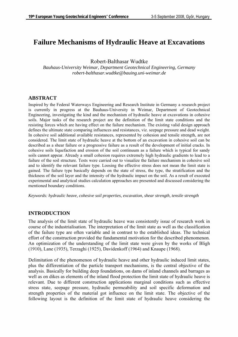
Figure 1. Schematic illustration of hydraulic heave on a building pit wall
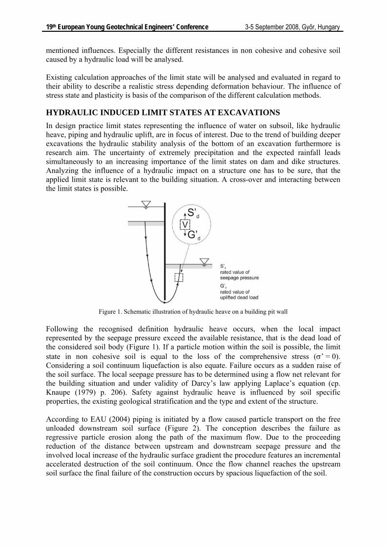
Following the recognised definition hydraulic heave occurs, when the local impact represented by the seepage pressure exceed the available resistance, that is the dead load of the considered soil body (Figure 1). If a particle motion within the soil is possible, the limit state in non cohesive soil is equal to the loss of the comprehensive stress (σ’ = 0). Considering a soil continuum liquefaction is also equate. Failure occurs as a sudden raise of the soil surface. The local seepage pressure has to be determined using a flow net relevant for the building situation and under validity of Darcy’s law applying Laplace’s equation (cp. Knaupe (1979) p. 206). Safety against hydraulic heave is influenced by soil specific properties, the existing geological stratification and the type and extent of the structure. According to EAU (2004) piping is initiated by a flow caused particle transport on the free unloaded downstream soil surface (Figure 2). The conception describes the failure as regressive particle erosion along the path of the maximum flow. Due to the proceeding reduction of the distance between upstream and downstream seepage pressure and the involved local increase of the hydraulic surface gradient the procedure features an incremental accelerated destruction of the soil continuum. Once the flow channel reaches the upstream soil surface the final failure of the construction occurs by spacious liquefaction of the soil.
19th European Young Geotechnical Engineers’ Conference 3-5 September 2008, Győr, Hungary
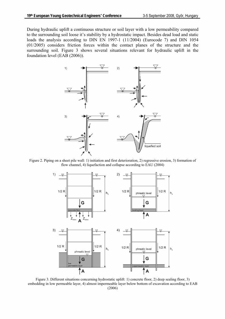
During hydraulic uplift a continuous structure or soil layer with a low permeability compared to the surrounding soil loose it’s stability by a hydrostatic impact. Besides dead load and static loads the analysis according to DIN EN 1997-1 (11/2004) (Eurocode 7) and DIN 1054 (01/2005) considers friction forces within the contact planes of the structure and the surrounding soil. Figure 3 shows several situations relevant for hydraulic uplift in the foundation level (EAB (2006)).
Figure 2. Piping on a sheet pile wall: 1) initiation and first deterioration, 2) regressive erosion, 3) formation of
flow channel, 4) liquefaction and collapse according to EAU (2004)
Figure 3. Different situations concerning hydrostatic uplift: 1) concrete floor, 2) deep sealing floor, 3)
embedding in low permeable layer, 4) almost impermeable layer below bottom of excavation according to EAB (2006)
19th European Young Geotechnical Engineers’ Conference 3-5 September 2008, Győr, Hungary
The mentioned failure types share a loss of stability by water. They differ in the kind of loosing stability, the place of failure initiation, the course of failure and failure kinematics. Shear resistance or deformation energy are not considered by the limit states. Thus especially in cohesive soil an additional safety margin exists. In Detail hydraulic heave and hydraulic uplift can be varied in the considered soil volume and the type of hydraulic impact (hydrodynamic vs. hydrostatic). The limit state of hydraulic heave is characterised by a loss of effective stress inside the soil. Hydraulic uplift considers the limit state in the contact plane between soil and a massive structure or between permeable and impermeable soil layers. Piping and hydraulic heave are induced by a seepage pressure. However limit states are defined on different locations. Especially a consideration of hydraulic heave in cohesive soil leads to additional differences between the mentioned failure types.
HYDRAULIC HEAVE IN DESIGN PRACTICE Stability analysis against hydraulic heave is relevant for various building applications. The limit state is influenced by basic factors like geometrical constraints and the geological as well as hydrological periphery. In detail those are: - subsoil stratigraphy, permeability of soil layers - flow net caused by structure, maximum hydraulic gradient imax - properties of flow impacted soil, weight and shear strength - soil sensitivity against particle transport mechanisms, change of permeability Corresponding to the specifications of Eurocode 7 (DIN EN 1997-1 (11/2004)), equation (2.9a) and (2.9b), the limit state is defined as follows:
dst;k G;dst dst;d stb;d stb;k G;stbu u⋅ γ = ≤ σ = σ ⋅ γ (1)
dst;k G;dst dst;d stb;d stb;k G;stbS S G ' G '⋅ γ = ≤ = ⋅ γ (2)
The approaches above provide an analysis regarding to total and effective stress. The impact is realised as seepage pressure udst and force of the current Sdst. Resistances are activated by overburden pressure resulting from saturated weight σstb or by the effective weight of the soil displayed as a force G’stb. The dimension of the failure area is defined by the structure type and varies at excavations between the corners and the walls. An additional consideration of soil specific resistances is not provided. The valid german code (DIN 1054 (01/2005)), equation (62), defines the limit state in comparison to the Eurocode 7 (DIN EN 1997-1 (11/2004)) as equilibrium of loads resulting from the effective weight and the seepage pressure:
k H k G,stbS' G '⋅ γ ≤ ⋅ γ (3)
Exemplary for a sheet pile wall on an excavation in ground water the failure area is defined at the soil abutment of the wall, with a width adequate to the half embedded length (Figure 4). The dimension of the soil body is only valid for broad excavations. Additionally to the definition in the Eurocode 7 (DIN EN 1997-1 (11/2004)) the existing force of current can be considered as a function depending on the soil type by using the safety factor γH. According to this for soils like gravel, gravel sand, at least medium dense sand (d > 0,2 mm) and minimum stiff clayed cohesive soil a beneficial percolation behaviour can be assumed. In this context unfavourable behaviour is valid for loose sand, fine-grain sand, silt as well as soft cohesive soil.
19th European Young Geotechnical Engineers’ Conference 3-5 September 2008, Győr, Hungary
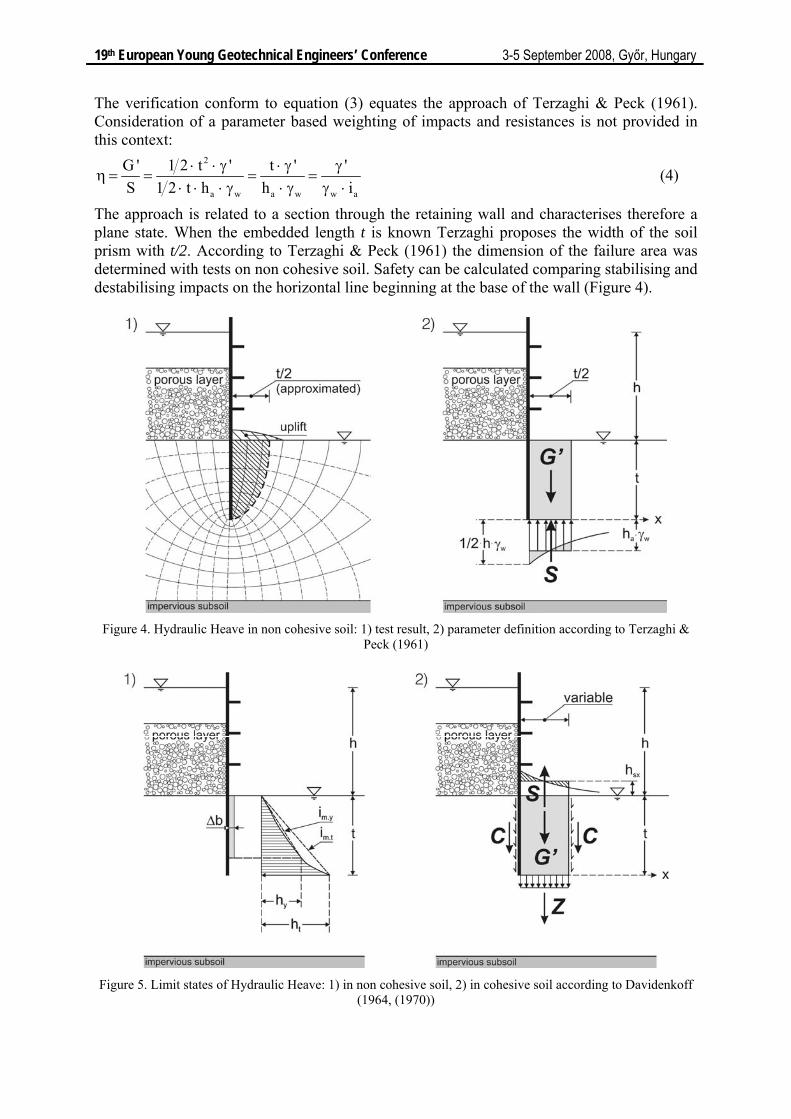
The verification conform to equation (3) equates the approach of Terzaghi & Peck (1961). Consideration of a parameter based weighting of impacts and resistances is not provided in this context:
2
a w a w w a
G ' 1 2 t ' t ' 'S 1 2 t h h i
⋅ ⋅ γ ⋅ γ γη = = = =
⋅ ⋅ ⋅ γ ⋅ γ γ ⋅ (4)
The approach is related to a section through the retaining wall and characterises therefore a plane state. When the embedded length t is known Terzaghi proposes the width of the soil prism with t/2. According to Terzaghi & Peck (1961) the dimension of the failure area was determined with tests on non cohesive soil. Safety can be calculated comparing stabilising and destabilising impacts on the horizontal line beginning at the base of the wall (Figure 4).
Figure 4. Hydraulic Heave in non cohesive soil: 1) test result, 2) parameter definition according to Terzaghi &
Peck (1961)
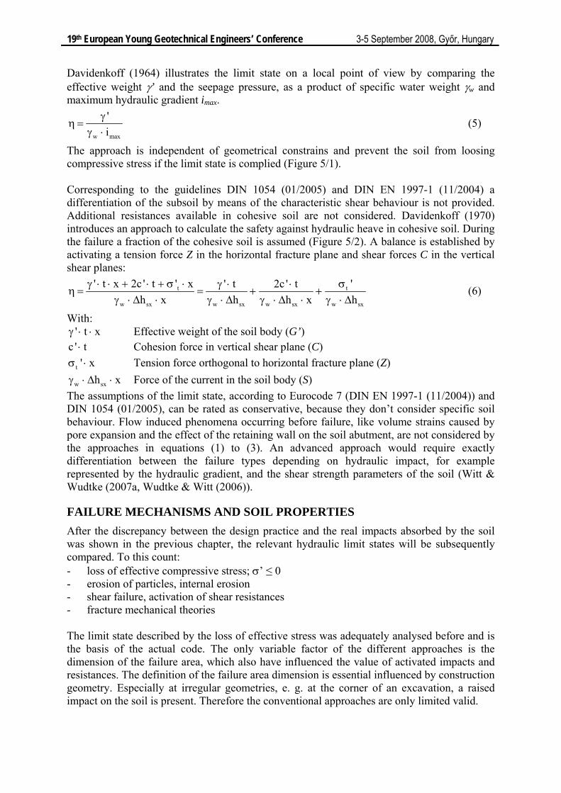
Figure 5. Limit states of Hydraulic Heave: 1) in non cohesive soil, 2) in cohesive soil according to Davidenkoff
(1964, (1970))
19th European Young Geotechnical Engineers’ Conference 3-5 September 2008, Győr, Hungary
Davidenkoff (1964) illustrates the limit state on a local point of view by comparing the effective weight γ’ and the seepage pressure, as a product of specific water weight γw and maximum hydraulic gradient imax.
w max
'iγ
η =γ ⋅
(5)
The approach is independent of geometrical constrains and prevent the soil from loosing compressive stress if the limit state is complied (Figure 5/1). Corresponding to the guidelines DIN 1054 (01/2005) and DIN EN 1997-1 (11/2004) a differentiation of the subsoil by means of the characteristic shear behaviour is not provided. Additional resistances available in cohesive soil are not considered. Davidenkoff (1970) introduces an approach to calculate the safety against hydraulic heave in cohesive soil. During the failure a fraction of the cohesive soil is assumed (Figure 5/2). A balance is established by activating a tension force Z in the horizontal fracture plane and shear forces C in the vertical shear planes:
t t
w sx w sx w sx w sx
' t x 2c ' t ' x '' t 2c ' th x h h x h
γ ⋅ ⋅ + ⋅ + σ ⋅ σγ ⋅ ⋅η = = + +
γ ⋅ Δ ⋅ γ ⋅ Δ γ ⋅ Δ ⋅ γ ⋅ Δ (6)
With: ' t xγ ⋅ ⋅ Effective weight of the soil body (G’)
c ' t⋅ Cohesion force in vertical shear plane (C)
t ' xσ ⋅ Tension force orthogonal to horizontal fracture plane (Z)
w sxh xγ ⋅ Δ ⋅ Force of the current in the soil body (S) The assumptions of the limit state, according to Eurocode 7 (DIN EN 1997-1 (11/2004)) and DIN 1054 (01/2005), can be rated as conservative, because they don’t consider specific soil behaviour. Flow induced phenomena occurring before failure, like volume strains caused by pore expansion and the effect of the retaining wall on the soil abutment, are not considered by the approaches in equations (1) to (3). An advanced approach would require exactly differentiation between the failure types depending on hydraulic impact, for example represented by the hydraulic gradient, and the shear strength parameters of the soil (Witt & Wudtke (2007a, Wudtke & Witt (2006)).
FAILURE MECHANISMS AND SOIL PROPERTIES After the discrepancy between the design practice and the real impacts absorbed by the soil was shown in the previous chapter, the relevant hydraulic limit states will be subsequently compared. To this count: - loss of effective compressive stress; σ’ ≤ 0 - erosion of particles, internal erosion - shear failure, activation of shear resistances - fracture mechanical theories The limit state described by the loss of effective stress was adequately analysed before and is the basis of the actual code. The only variable factor of the different approaches is the dimension of the failure area, which also have influenced the value of activated impacts and resistances. The definition of the failure area dimension is essential influenced by construction geometry. Especially at irregular geometries, e. g. at the corner of an excavation, a raised impact on the soil is present. Therefore the conventional approaches are only limited valid.
19th European Young Geotechnical Engineers’ Conference 3-5 September 2008, Győr, Hungary
Taking erosion as relevant limit state into consideration a release of single particles is relevant. In former analyses of the author it could be demonstrated, that already for soil with low cohesion the limit state is not relevant (cp. Witt & Wudtke (2006b, (2007a), Wudtke & Witt (2006)). At the comparison erosion criteria by Rehfeld (1967), Davidenkoff (1976), Müllner (1991) and Zou (2000) were evaluated. The dominance of other limit states is mainly reflected by the required high hydraulic gradient, necessary for an initial particle motion. With the objective of gaining a better understanding of flow induced failure in cohesive soil, tests were carried out (cp. Witt & Wudtke (2007b), Wudtke & Witt (2008)). As result of the tests it was possible to identify and define a failure course consisting of 4 phases. According to that after a flow forced pore expansion of the soil an initial crack is developed (1.). During the model test the crack first appeared at the foot of the exemplary retaining wall. Due to a constantly flow further cracks were developed (2). The increasing destruction of the soil continuum finally leads to the generation of a preferred flow path and allows a continuously compensation of the upstream and downstream potentials. Due to further flow the interim developed soil body was successive destroyed. The impact caused by the potential difference was explicit larger than the expectation assuming the limit state by loosing effective stress. Although the test had only a qualitative character it could be shown, that the assumption of the limit state conform to the valid code discounts existent soil resistances. As a consequence of the test results the possibility to interpret the limit state as discrete body with shear forces acting within the contact planes to the surrounding subsoil was developed. To this in Witt & Wudtke (2006a) and Wudtke & Witt (2006) a first approach was presented. The problem was solved by defining the failure area corresponding to the orientation and distribution of the valid flow net. The contact plane to the subsoil was defined as parabolic function with a peak situated at the foot of the retaining wall. Although the consideration of additionally existent cohesive soil resistances is provided, the approach has to be evaluated critically. According to the test results the scenario of a discrete failure body was only indirect determined. Ultimately due to the detected ongoing destruction of the soil body the total soil resistance was realised, but a shear failure as limit state cannot be regarded as description of the situation. Exemplary to the multisided, not with a shear failure connected, a possible explanation of the limit state is given by the interpretation of the test results in Kolymbas (2008). Another possible approach to determine the limit state is given by the theory of fracture mechanics. Basis of the theory was originally defined by Griffith (1921). The theory is not yet executed to this special situation of hydraulic induced failure. Based on the determination of initial soil damage by cracks the execution of the theory is appropriate. Assuming total stress different problems, e. g. on soil build barrages (Vallejo (1993)), solutions were derived. Basic advantage of the method is the implementation of the deformation behaviour and therefore the consideration of different influences resulting from pit excavation and groundwater lowering. During crack formation and final crack expansion the dissipated energy can be considered as additional soil resistance. On the one hand the method presented the most detailed possibility to predict the limit state, on the other it depends extremely on external constrains, like the stress state and the type of influence acting on the soil (type I – tension crack; type II – shear crack). Especially the stress dependent soil specific tensile strength is essential for the calculation.
19th European Young Geotechnical Engineers’ Conference 3-5 September 2008, Győr, Hungary
SUMMARY Facing the prospective closer interacting of infrastructures an effective protection of living space and routes of transport become more important and therefore among others demands on optimal dimensioning against hydraulic heave. The consideration of existent soil resistances is sensible against this background. The actual valid design approach concerning hydraulic heave defines, due to sole consideration of dead load, the limit state for non cohesive soil as a kind of liquefaction. Resistances like friction forces caused by a flow induced increase of the soil volume and pore expansion or additional soil bracing generated by static loads are not considered. Currently, there is no separate design approach provided for hydraulic heave in cohesive soil. Although the limit state in cohesive soil is defined when effective stress becomes zero, an effective stress σ’ ≤ 0 doesn’t necessarily represent a failure of the soil. Assuming a failure with a discrete soil body or a failure mechanism according to the fracture mechanical theory a additional consideration of existent soil resistances is possible. Next step of the current research project is the execution of tests to detect the realistically present tensile strength of cohesive soil. Final objective of the project is the development of an integral approach representing the limit state of hydraulic heave at excavations in cohesive soil.
ACKNOWLEDGEMENT The presented results of experimental and analytical analysis’s are based on conclusions of an actual research project “Hydraulic Heave in Cohesive Soil”, sponsored by the Federal Waterways Engineering and Research Institute in Germany. The funding assistance provided by the Bauhaus-University Weimar in support of this project is gratefully acknowledged.
REFERENCES DIN 1054. (01/2005). Baugrund - Sicherheitsnachweise im Erd- und Grundbau.
Normenausschuss Bauwesen (NABau) im DIN. DIN Deutsches Institut für Normung e.V. DIN EN 1997-1. (11/2004). Eurocode 7: Entwurf, Berechnung und Bemessung in der
Geotechnik - Teil 1: Allgemeine Regeln. Normenausschuss Bauwesen (NABau) im DIN. DIN Deutsches Institut für Normung e.V.
Bligh, W. G. (1910). Dams, Barrages and Weirs on Porous Foundations. Engineering News, Vol. 64 (26), 708 - 710
Davidenkoff, R. (1964). Zur Berechnung des Hydraulischen Grundbruches. Wasserwirtschaft, Vol. (9), 230 - 235
Davidenkoff, R. (1970). Unterläufigkeit von Stauwerken. Werner-Verlag GmbH, 978-3804113107.
Davidenkoff, R. (1976). Anwendung von Filtern im Wasserbau. Verlag Ernst & Sohn, 3-433-00753-5.
DGGT - Deutsche Gesellschaft für Geotechnik e. V. (2006). EAB - Empfehlungen des Arbeitskreises Baugruben. Ernst & Sohn - Verlag für Architektur und technische Wissenschaften GmbH, Berlin. 3-433-02853-2.
DGGT - Deutsche Gesellschaft für Geotechnik e. V. (2004). EAU - Empfehlungen des Arbeitsausschusses Ufereinfassungen, Häfen und Wasserstraßen. Ernst & Sohn - Verlag für Architektur und technische Wissenschaften GmbH, Berlin. 3-433-02852-4.
19th European Young Geotechnical Engineers’ Conference 3-5 September 2008, Győr, Hungary
Griffith, A. A. (1921). The Phenomena of Rupture and Flow in Solids. Philosophical Transactions of the Royal Society of London, Series A, containing Papers of a mathematical or physical Character, Vol. 221, 163 - 198,
Knaupe, W. (1968). Hydraulischer Grundbruch an Baugrubenumschließungen. Deutsche Bauenzyklopädie, Schriftenreihen der Bauforschung, Reihe Ingenieur- und Tiefbau,
Knaupe, W. (1979). Baugrubensicherung und Wasserhaltung. VEB Verlag für Bauwesen, Kolymbas, D. (2008). Hydraulic Fracture as Rayleigh-Taylor Instability. Geotechnical
Engineering for Disaster Mitigation and Rehabilitation, Proceedings of the 2nd International Conference, Nanjing (China),
Lane, E. W. (1935). Security from under-seepage masonry Dams on Earth Foundations. Transactions American Society of Civil Engineers, Vol. 100 (1919), 1235 - 1351
Müllner, B. (1991). Beitrag zur Untersuchung der Erosionssicherheit bindiger Mischböden bei vertikaler Durchströmung. Mitteilungen des Fachgebietes Grundbau, Gesamthochschule Kassel - Universität.
Rehfeld, E. (1967). Die Erosionsbeständigkeit bindiger Lockergesteine - die wichtigste Grundlage zur Dimensionierung von Dichtungsschichten aus natürlichem Erdstoff. Wissenschaftliche Zeitschrift der TU Dresden, Vol. 16 (5), 1431 - 1437
Terzaghi, K. (1925). Erdbaumechanik auf bodenphysikalischer Grundlage. Verlag F. Deutike, Terzaghi, K. & Peck, R. B. (1961). Die Bodenmechanik in der Baupraxis. Springer-Verlag, Vallejo, L. E. (1993). Shear stresses and the hydraulic fracturing of earth dam soils. Soils and
Foundations, Vol. 33 (3), 14 - 27 Witt, K. J. & Wudtke, R.-B. (2006a). Hydraulisch bedingte Versagensformen in der Sohle von
Baugruben. Hydraulischer Grundbruch in bindigem Boden, 1, Bundesanstalt für Wasserbau (BAW) & Bauhaus-Universität Weimar.
Witt, K. J. & Wudtke, R.-B. (2006b). Spannungszustände und Grenzbedingungen an einer Baugrubenwand in bindigem Boden. Hydraulischer Grundbruch in bindigem Boden, 2, Bundesanstalt für Wasserbau (BAW) & Bauhaus-Universität Weimar.
Witt, K. J. & Wudtke, R.-B. (2007a). Versagensformen des Hydraulischen Grundbruches an einer Baugrubenwand. 22. Christian Veder Kolloquium, Graz, 12. & 13. April 2007, 229 - 242.
Witt, K. J. & Wudtke, R.-B. (2007b). Visualisierung des durch Strömung verursachten Bruchverhaltens in bindigen Böden. Hydraulischer Grundbruch in bindigem Boden, 3, Bundesanstalt für Wasserbau (BAW) & Bauhaus-Universität Weimar.
Wudtke, R.-B. & Witt, K. J. (2006). A Static Analysis of Hydraulic Heave in Cohesive Soil. 3rd International Conference on Scour and Erosion, Amsterdam, 1 - 3 November 2006, 251.
Wudtke, R.-B. & Witt, K. J. (2008). Einfluss von Bodenwiderständen beim Hydraulischen Grundbruch. 6. Kolloqium Bauen in Boden und Fels, Ostfildern, 22. & 23. Januar 2008,
Zou, Y. (2000). Der vom Spannungszustand und Bodengefüge abhängige Erosionsdurchbruch bindiger Böden. Wasserwirtschaft, Vol. 90 (11), 554 - 559