failure criteria of unreinforced grouted brick masonry...
TRANSCRIPT
Transaction A: Civil EngineeringVol. 16, No. 6, pp. 502{511c Sharif University of Technology, December 2009
Failure Criteria of Unreinforced Grouted BrickMasonry Based on a Biaxial Compression Test
B. Badarloo1, A.A. Tasnimi1;� and M.S. Mohammadi1
Abstract. To de�ne failure under biaxial stress, a three-dimensional surface in terms of two principalstresses and their orientation to the bed joints is required. This article describes a series of biaxialcompression tests on full-scale brick specimens. Tests were performed on square unreinforced groutedbrick masonry specimens with the principal compressive stresses oriented at 0 and 90 degree angles tothe bed joints, and a failure surface was obtained in terms of these parameters. Test results indicatedthat the masonry strength under equal biaxial compression is higher by about 36% on average than thatunder uniaxial compression; the in uence of joint orientation is very insigni�cant and negligible for thesemodels.
Keywords: Failure criteria; Masonry panel; Principal stress; Biaxial stresses; Bed joints.
INTRODUCTION
Most masonry structures are subjected to a complexstate of stress during their lifetime. Shear walls, in�llwalls in frame structures and walls supported by beamsetc. are in a state of biaxial stress when subjected toin-plane loading. Based on the location of masonrypanels within a building, biaxial stress states can beCompressive-Compressive State (CCS), Compressive-Tensile State (CTS) and Tensile-Tensile State (TTS).Little emphasis has been placed on the development ofa fundamental theory of failure that could be applied toany case of in-plane loading. Computer-based numeri-cal techniques have made the need for this informationmore pressing, as the de�nition of local failure is ofprime importance in modeling masonry behavior realis-tically. Masonry exhibits distinct directional propertiesbecause of the in uence of the unit's arrangement andthe mortar joints, which act as planes of weakness.Its failure cannot therefore be de�ned simply in termsof a criterion based on the principal stresses at anypoint. The in uence of bed joint orientation relative toprincipal stresses is the main variable that must alsobe taken into account. Depending on the orientationof the joints to the applied stresses, failure can occur in
1. Department of Civil Engineering, Tarbiat Modares Univer-sity, Tehran, P.O. Box 14155-143, Iran.
*. Corresponding author. E-mail: [email protected]
Received 28 February 2009; received in revised form 11 July2009; accepted 31 August 2009
the joints alone or in some form of combined mechanisminvolving mortar and the masonry unit. Thus, to de�nemasonry failure completely, a three-dimensional failuresurface in terms of the principal stresses, �1 and �2,and their respective orientations to the bed joint of 0and 90� is required. To derive this surface, biaxial testsmust be performed to cover the CCS, CTS and TTSprincipal stress domains. In practice, the most criticalregions are those of CTS and CCS.
This paper reviews research carried out at theStructural Laboratory in Tarbiat Modares University(TMU) on the biaxial strength of masonry and de-scribes an investigation into the biaxial strength of full-scale brick masonry. This involved biaxial compressiontests on square grouted brick masonry specimens withvarying principal stress ratios and bed joint orienta-tions. The study forms part of a series of tests aimedat developing a complete (�1, �2, �) failure surface forall principal stress combinations.
PREVIOUS RESEARCH
For a long time, the signi�cance of joint orientation tothe stress state of masonry panels has been of interestto many researchers. Johnson and Thompson [1]described diametral tests on brick masonry discs, whichproduced indirect tensile stresses on joints inclined atvarious angles to the compressive load. Similar tests ongrouted and un-grouted concrete masonry have beenreported by Drysdale and Hamid [2]. The in uence
Failure Criteria of Unreinforced Grouted Brick Masonry 503
of bed joint orientation has also been shown in manyinvestigations carried out into shear wall behavior [3].There have been few attempts to obtain a generalfailure criterion for masonry because of the di�culty indeveloping a representative biaxial test, as well as thelarge number of tests involved. The problem has beenqualitatively discussed by Yokel and Fatta1 [4] andHendry [5]. Samarasinghe [6] and Samarasinghe andHendrye [7] obtained a (�1, �2, �) failure surface for thetension-compression principal stress range from testson one-sixth scale brickwork. Page [8-10] studied thebehavior of brick masonry under biaxial CCS, CTS andTTS of stresses. He proposed failure surfaces for thethree biaxial stress cases in which he observed that thebed joint orientation has little in uence on the shapeof the failure surface for the case of CCS, but exertssigni�cant in uence under the CTS and TTS of stress.Also, it was found that bed joint orientation a�ectedthe failure pattern only when one of the principalstresses dominated. Similar observations were alsomade by Samarasinghe [6] on the behavior of brickmasonry under biaxial compression-tension. The pro-posed failure surfaces were in terms of principal stressesand bed joint orientation. Ganz and Thurlimann [11],Ganz [12] and Dhanasekar et al. [13] proposed failuresurfaces in terms of orthogonal stresses and shearstress. The in uence of joint orientation has been foundto be less signi�cant for grouted concrete masonry.From a comprehensive series of biaxial tests on full-scale grouted concrete masonry (both reinforced andun-reinforced), Hegemier et al. [14] found the in uenceof the bed joint angle to be minimal and the behavioressentially isotropic. However, this isotropy could bedestroyed by improper selection of block and groutstrengths. Lourenco [15] developed a material modelfor masonry that combined the modern plasticity con-cepts (hardening, softening, ow rule and evolutionlaws) with an anisotropic behavior along each materialaxis. During the past decade, very limited research hasbeen carried out on the behavior of reinforced and un-reinforced brick masonry under biaxial stress states.Alshebani and Sinha [16] investigated the behaviorof brick masonry under a pseudo dynamic (cyclic)biaxial stress state. Naraine and Sinha [17] studied thebehavior of brick masonry under cyclic biaxial compres-sion and obtained that masonry under cyclic biaxialcompression can exhibit three distinct stress-straincurves; they proposed a generalized interaction formulafor this failure in terms of stress invariant for therange of stress ratios considered. Also, Senthivel andUzoegbo [18] experimentally investigated the failurecriterion of unreinforced masonry under biaxial pseudodynamic loading. They proposed a general analyticalexpression for the envelope interaction curves, commonpoint interaction curves and stability point interactioncurves. They suggested that by assigning suitable
values for equation parameters, the expression couldbe used to determine the peak stress of the envelopecurve, the common point curve and the stability pointcurve. The aim of this research is to produce thefailure criteria of unreinforced grouted brick masonrypanels, for the purpose of a design process. Thispaper describes the tests carried out on square groutedunreinforced brick masonry panels with the principalcompressive stresses oriented at 0 and 90 degree anglesto the bed joints, and a failure surface was obtained interms of these parameters.
EXPERIMENTAL PROGRAM
The experimental program involved testing full-scalegrouted unreinforced brick masonry panels undermonotonic biaxial loading that induced a CCS ofstress. The angle of inclination between the horizontalprincipal stresses and the bed joints was limited to 0�and 90�. Five principal stress ratios were consideredfor the investigation as fn
fp = 0, 0.2, 0.5, 1, 2, 5 wherefn and fp are the applied stresses normal to the bedjoint (� = 90�) and parallel to the bed joint (� = 0�),respectively.
Description of Test Specimens
This paper presents an experimental program of testingseven masonry full-scale grouted unreinforced brickmasonry specimens under monotonic biaxial compres-sion. All panel specimens were constructed with threelayers, consisting of one single wythe of 221:9 � 110 �68:5 mm solid clay bricks, one single wythe of 204:7�58:5�54:9 mm clay hollow bricks and a 51.5 mm thickgrout layer between the brick wythes. The overalldimension of each panel was 950 � 95 � 220 mm fromwhich a central area of 600 � 600 mm2 was selectedfor measurement. To identify specimens, they werenominated mainly by four characters for specimensunder uniaxial compression, and three characters fol-lowed by one or two digits corresponding to the normalto parallel stress ratio for specimens under biaxialcompression. For example, the brick panel, underthe uniaxial compression load (fn = 0) parallel tothe bed joint is named UPCP, and that under biaxialcompression with (� = fn
fp = 0:2) is named BPC02.Table 1 summarizes all specimens with their relevantstates of stress.
A chemical admixture was used to compensatefor shrinkage and enhance the workability of the grout.The grout was placed using internal vibration to obtaingood consolidation. To ensure uniform workmanship,all test specimens were constructed by the same masonand were cured under damped conditions for 28 daysbefore testing. The overall size of the fabricated spec-imens was 950 mm � 950 mm � 220 mm. Generally,
504 B. Badarloo, A.A. Tasnimi and M.S. Mohammadi
Table 1. Specimens identi�cation corresponding to their loading state.
Specimen Name State of Applied Load fn fp � = fn=fpUPCP Uniaxial compression parallel to bed joint -
p-
UPCN Uniaxial compression normal to bed jointp
- -
BPC1 Equal biaxial compressionp p
1
BPC2 Biaxial compressionp p
2
BPC05 Biaxial compressionp p
0.5
BPC5 Biaxial compressionp p
5
BPC02 Biaxial compressionp p
0.2
solid clay bricks are used for masonry brick building,in�ll panels etc., and hollow clay bricks are used forthe �nishing of brick masonry (face brick) walls in thecountry. For convenience, the solid clay brick and thehollow clay brick are, hereafter, referred to as C-Brickand F-Brick, respectively.
Material Properties
Quality control samples were obtained for the mortar,grout, C-Bricks, F-Bricks and the masonry units duringthe construction of all specimens.
The mortar mix proportions was an ASTM C270-92 type-S mortar, comprised of 1 part Portland cement,5.81 parts sand and 0.9 parts water by weight. Fifteenmortar 50 mm cube specimens were made from eachmortar mix and tested after 28 days for compressivestrength as per ASTM C-109-92.
The average mortar compressive strength ob-tained from cube compression tests was 12.46 MPa.
The grout mix proportions were an ASTM C476-02 of 1 part type-I Portland cement, 3.68 parts sand,2.25 parts 12 mm nominal maximum-size broken stone,0.018 parts of a commercial chemical admixture (SikaGrout-Aid) and 0.8 parts water by weight. Six grout100 mm cube specimens were made from each groutmix and tested after 28 days for compressive strength,as per ASTM C1019-02. The average grout compres-sive strength obtained from cube compression tests was22.84 MPa.
In order to evaluate the compressive strengthof masonry, �fteen 4-course masonry prisms (coupletspecimens) were tested, as per ASTM C-1314-02a. Theaverage prism compressive strength was 4.0 and 6.4MPa for the F-Brick and C-Brick prisms, respectively.The average compressive strength of ten C-Bricks andten F-Bricks was 34 and 32.6 MPa, respectively. Theaverage compressive strength of masonry prisms is lessthan the average compressive strength of the used C-Bricks, F-Bricks and mortar. This is attributed tothe failure mechanism of masonry prisms in whichthe vertical splitting of the bricks is occurred priorto the crushing of the mortar. In other words, the
vertical splitting of the bricks due to the di�erentmaterial properties of the bricks and mortar leads toa premature failure of the prisms. This is because thehigher Poisson ratio of the mortar results in a tendencyfor lateral mortar tensile strains to exceed lateral brickstrains [19]. Therefore, the normal compression andlateral biaxial tension in the bricks reduces its crushingstrength and induces a tendency for vertical splitting.In such situations, the vertical splitting strength of thebricks was less than the compressive strength of thebricks and that of mortar. This phenomenon indicatesthe failure of bricks in the form of vertical splittingprior to the failure of prisms in compression.
As no ASTM testing procedures exist for shearstrength determination, the modi�ed triplet specimenfor pure shear was used to obtain the mortar shearstrength and friction coe�cient [20]. This specimenrepresents the actual shear loading case of masonrywalls along the mortar bed-joints. The value of thebrick-mortar interface bond strength (mortar shearbond strength) was 0.451 Mpa and the average coef-�cient of friction of the mortar joint was 0.65.
To evaluate the exural bond strength of C-Brick and F-Brick masonry, seven and eight 5-coursemasonry units were tested as per ASTM C1072-00a.The average exural bond strength was 2.52 and 1.96MPa for the C-Brick and H-Brick masonry units,respectively.
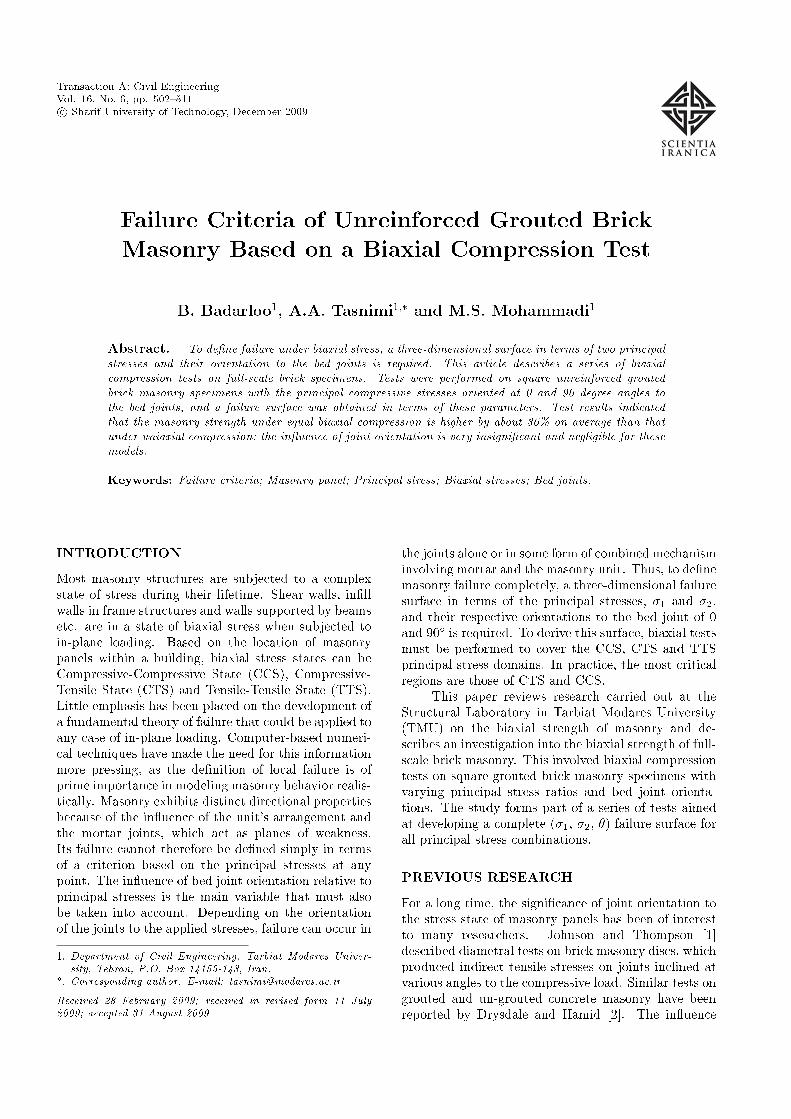
According to the ASTM C1314-02a, the compres-sive strength of seven 4-course masonry panel prisms(couplet specimens) was carried out and the averagepanel prism compressive strength obtained as 7.1 MPa.Table 2 summarizes the properties of each specimenand Figure 1 illustrates the geometry and dimensionsof the test specimens
Loading Arrangement
The test setup, including a specimen, reaction ringand the monotonic biaxial loading arrangement (CCS),is shown in Figure 2. The biaxial steel ring wasdesigned so that the maximum deformation under aprospective maximum load would be negligible. A
Failure Criteria of Unreinforced Grouted Brick Masonry 505
Table 2. Summary of result of auxiliary assemblages after 28 days.
Test TypeSpecimen Compression (MPa) Flexural (MPa) Compression (MPa)Number C-Brick F-Brick C-Brick F-Brick Panel Prism
1 5.5 4.4 2.29 2.23 6.7
2 5.7 3.8 2.64 1.94 5.8
3 5.7 4.5 3.31 1.67 8.2
4 6.0 2.6 2.42 2.03 5.8
5 9.7 3.5 1.87 1.99 8.1
6 6.1 5 1.76 1.73 7.9
7 5.6 4.4 2.72 2.12 7.5
8 6.8 - 3.19 - -
Average 6.4 4.0 2.52 1.96 7.1
Figure 1. Test setup and failure of auxiliary assemblages.
biaxial state of stress was achieved by applying in-plane loads with the use of two double-acting hydraulicactuators aligned in two orthogonal directions as shownin Figure 2. The capacity of each hydraulic actuatoris 3000 kN for both compression and tension. Theload measurement was carried out by installing twoload cells placed in line with the central axes of thepanel and connected to a data-logger system of type
TML. In order to apply a distributed load to thespecimen, a steel rigid beam made of PL850 � 250� 30 mm in I-section, which was su�ciently sti�enedwith PL850 � 250 � 10 mm vertical sti�eners, wasutilized (Figure 3a). This rigid beam was used as aloading platen on four sides of the specimen. Whenthe masonry panel specimen is subjected to biaxialcompression loads, it may be under con�ning pressure

506 B. Badarloo, A.A. Tasnimi and M.S. Mohammadi
Figure 2. General setup for biaxial tests.
Figure 3. Schematic arrangement and geometry of masonry panel specimen.
along its loaded surfaces due to friction between thesolid platens of the test setup and the masonry panel'sbearing surface. The e�ect of such restraint may resultin an increase of the apparent strength of the testspecimen [21-24]. To minimize such a con�nement ofthe specimen due to friction and thus to ensure a moreuniform state of stress is imposed on the specimen, 10mm thick Te on pads were used on all four bearingsurfaces of the brick masonry panel. Figure 3b shows aschematic arrangement of loading platens, a masonrypanel and Te on pads mounted between them. Toavoid unexpected additional con�nement, due to thecontact of adjoining plates, when the specimen is underbiaxial compression, the width of the loading plates was850 mm (100 mm less than the specimen width).
INSTRUMENTATION
The masonry specimens were instrumented withLVDTs (linearly variable displacement transducers)aligned in two principal directions and two diagonaldirections on the C-Brick surface of the panel as shownin Figure 3c. The LVDTs were installed to measure the
axial, lateral and diagonal displacements over a �xedgauge length. The gauge lengths of 600 mm, 600 mmand 450 mm were adopted for the measurement of ax-ial, lateral and orthogonal deformations, respectively.A data-logger system was used to display, monitor andrecord the load and displacement measurements in realtime during the test. The ratio between horizontal andvertical loads was controlled in the real time of thetest.
RESULTS
A total of 7 specimens, including two uniaxial and�ve biaxial compression specimens, were tested. Forspecimens under biaxial compressive stresses, di�erentratios of stress normal to the bed joint (fn) to thestresses parallel to the bed joint (fp), were used in twogroups. For the �rst group, the ratios of 1, 2, 5 and 1were used for bed joint angles of 0� and 90� with respectto the horizontal axis. For the second group, the resultscorresponding to the ratios of 0, 0.2 and 0.5 wereobtained on the basis of symmetry of the specimens andloading conditions. The following paragraphs describe
Failure Criteria of Unreinforced Grouted Brick Masonry 507
the failure mode, crack propagation and the failurecriterion of all specimens.
Failure Modes
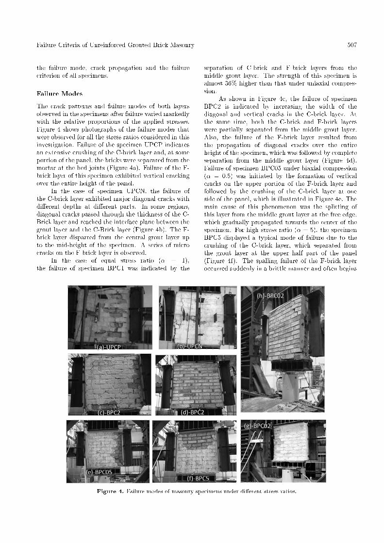
The crack patterns and failure modes of both layersobserved in the specimens after failure varied markedlywith the relative proportions of the applied stresses.Figure 4 shows photographs of the failure modes thatwere observed for all the stress ratios considered in thisinvestigation. Failure of the specimen UPCP indicatesan extensive crushing of the C-brick layer and, at someportion of the panel, the bricks were separated from themortar at the bed joints (Figure 4a). Failure of the F-brick layer of this specimen exhibited vertical crackingover the entire height of the panel.
In the case of specimen UPCN, the failure ofthe C-brick layer exhibited major diagonal cracks withdi�erent depths at di�erent parts. In some regions,diagonal cracks passed through the thickness of the C-Brick layer and reached the interface plane between thegrout layer and the C-Brick layer (Figure 4b). The F-brick layer disparted from the central grout layer upto the mid-height of the specimen. A series of microcracks on the F-brick layer is observed.
In the case of equal stress ratio (� = 1),the failure of specimen BPC1 was indicated by the
separation of C-brick and F-brick layers from themiddle grout layer. The strength of this specimen isalmost 36% higher than that under uniaxial compres-sion.
As shown in Figure 4c, the failure of specimenBPC2 is indicated by increasing the width of thediagonal and vertical cracks in the C-brick layer. Atthe same time, both the C-brick and F-brick layerswere partially separated from the middle grout layer.Also, the failure of the F-brick layer resulted fromthe propagation of diagonal cracks over the entireheight of the specimen, which was followed by completeseparation from the middle grout layer (Figure 4d).Failure of specimen BPC05 under biaxial compression(� = 0:5) was initiated by the formation of verticalcracks on the upper portion of the F-brick layer andfollowed by the crushing of the C-brick layer at oneside of the panel, which is illustrated in Figure 4e. Themain cause of this phenomenon was the splitting ofthis layer from the middle grout layer at the free edge,which gradually propagated towards the center of thespecimen. For high stress ratio (� = 5), the specimenBPC5 displayed a typical mode of failure due to thecrushing of the C-brick layer, which separated fromthe grout layer at the upper half part of the panel(Figure 4f). The spalling failure of the F-brick layeroccurred suddenly in a brittle manner and often begins
Figure 4. Failure modes of masonry specimens under di�erent stress ratios.
508 B. Badarloo, A.A. Tasnimi and M.S. Mohammadi
by vertical cracking at one of the loaded edges, whichpropagates into the panel height.
The failure of specimen BPC02, tested underbiaxial compression with low stress ratio (� = 0:2), wasindicated by the crushing of the C-brick layer on theleft-side of the panel and embarked on its splitting fromthe grout layer as shown in Figure 4g. Thereafter, theseparated fragments of the panel behave like individualcompression members. The failure of the F-brick layerof this specimen is shown in Figure 4h.
Due to the high compression strength of the groutlayer compared to that of F-brick and C-brick layers,the middle grout layer experienced no serious damagefor all specimens. The reason for this phenomenonis �rstly related to the high compression strength ofthe grout in comparison with the compression strengthof the masonry prisms and, secondly the bondingweakness at the interface of the C-brick, F-brick andthe grout layer. It seems that the e�ect of the secondfactor is more considerable.
Failure Surface
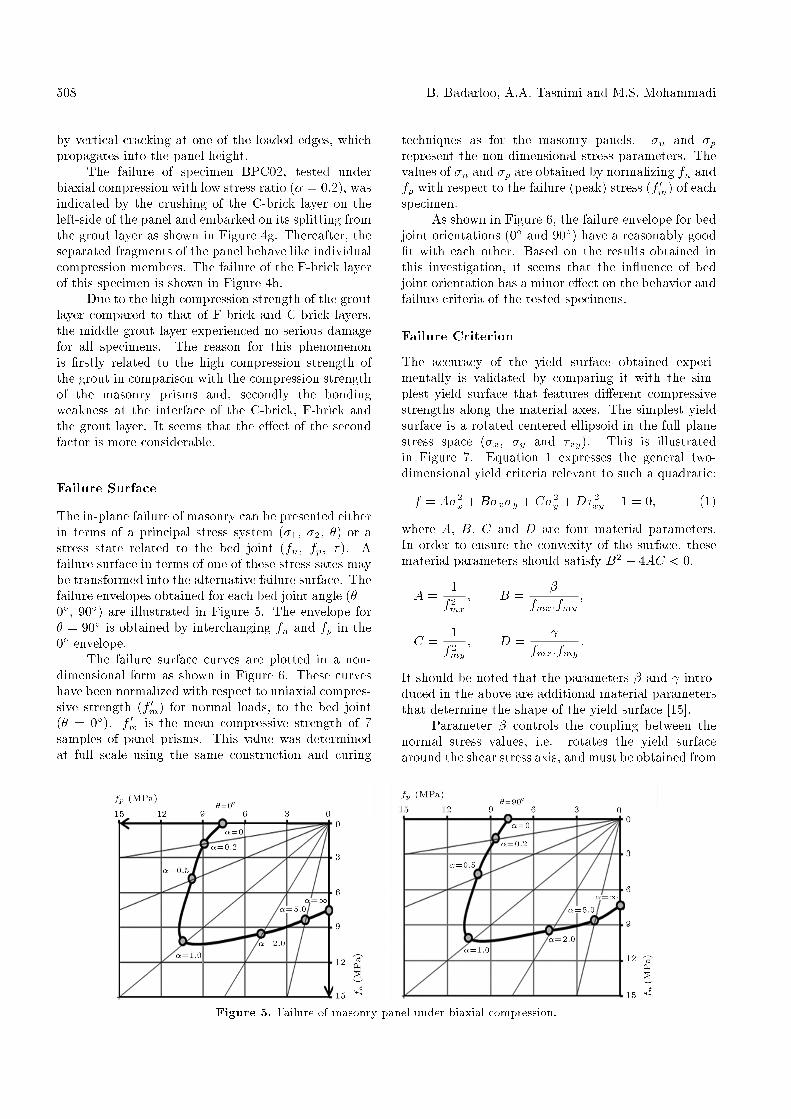
The in-plane failure of masonry can be presented eitherin terms of a principal stress system (�1, �2, �) or astress state related to the bed joint (fn, fp, �). Afailure surface in terms of one of these stress sates maybe transformed into the alternative failure surface. Thefailure envelopes obtained for each bed joint angle (� =0�, 90�) are illustrated in Figure 5. The envelope for� = 90� is obtained by interchanging fn and fp in the0� envelope.
The failure surface curves are plotted in a non-dimensional form as shown in Figure 6. These curveshave been normalized with respect to uniaxial compres-sive strength (f 0m) for normal loads, to the bed joint(� = 0�). f 0m is the mean compressive strength of 7samples of panel prisms. This value was determinedat full scale using the same construction and curing
techniques as for the masonry panels. �n and �prepresent the non-dimensional stress parameters. Thevalues of �n and �p are obtained by normalizing fn andfp with respect to the failure (peak) stress (f 0m) of eachspecimen.
As shown in Figure 6, the failure envelope for bedjoint orientations (0� and 90�) have a reasonably good�t with each other. Based on the results obtained inthis investigation, it seems that the in uence of bedjoint orientation has a minor e�ect on the behavior andfailure criteria of the tested specimens.
Failure Criterion
The accuracy of the yield surface obtained experi-mentally is validated by comparing it with the sim-plest yield surface that features di�erent compressivestrengths along the material axes. The simplest yieldsurface is a rotated centered ellipsoid in the full planestress space (�x, �y and �xy). This is illustratedin Figure 7. Equation 1 expresses the general two-dimensional yield criteria relevant to such a quadratic:
f = A�2x +B�x�y + C�2
y +D�2xy � 1 = 0; (1)
where A, B, C and D are four material parameters.In order to ensure the convexity of the surface, thesematerial parameters should satisfy B2 � 4AC < 0.
A =1f2mx
; B =�
fmx:fmy;
C =1f2my
; D =
fmx:fmy:
It should be noted that the parameters � and intro-duced in the above are additional material parametersthat determine the shape of the yield surface [15].
Parameter � controls the coupling between thenormal stress values, i.e. rotates the yield surfacearound the shear stress axis, and must be obtained from
Figure 5. Failure of masonry panel under biaxial compression.
Failure Criteria of Unreinforced Grouted Brick Masonry 509
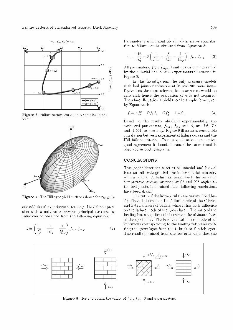
Figure 6. Failure surface curves in a non-dimensionalform.
Figure 7. The Hill type yield surface (shown for �xy � 0).
one additional experimental test, e.g. biaxial compres-sion with a unit ratio between principal stresses; itsvalue can be obtained from the following equation:
� =
1f2�� 1f2mx� 1f2my
!fmx:fmy: (2)
Parameter which controls the shear stress contribu-tion to failure can be obtained from Equation 3:
=�
16f2 � 9
�1f2mx� �f2mx� 1f2my
��fmx:fmy: (3)
All parameters, fmx, fmy, � and , can be determinedby the uniaxial and biaxial experiments illustrated inFigure 8.
In this investigation, the only masonry modelswith bed joint orientations of 0� and 90� were inves-tigated, so the term relevant to shear stress would bezero and, hence the evaluation of is not required.Therefore, Equation 1 yields to the simple form givenby Equation 4:
f = Af2x +Bfxfy + Cf2
y � 1 = 0: (4)
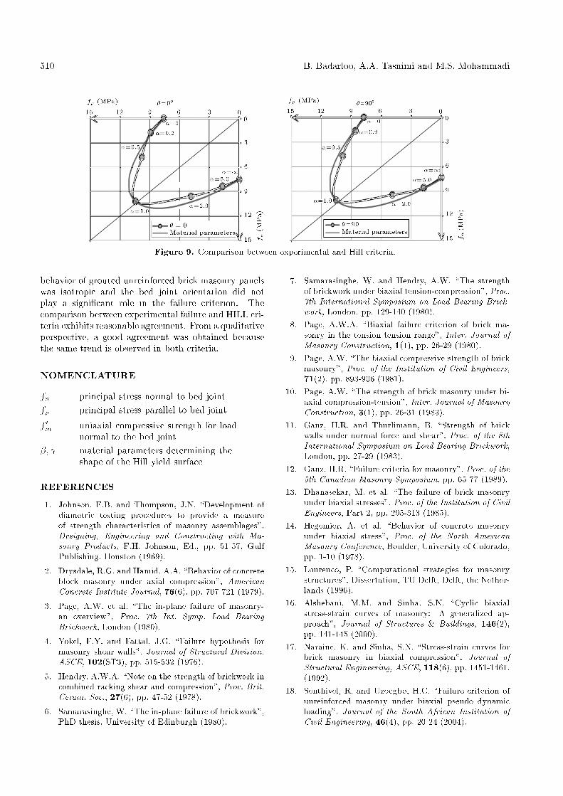
Based on the results obtained experimentally, theevaluated parameters, fmx, fmy and �, are 7.6, 7.5and -1.464, respectively. Figure 9 illustrates reasonablecorrelation between experimental failure curves and theHill failure criteria. From a qualitative perspective,good agreement is found, because the same trend isobserved in both diagrams.
CONCLUSIONS
This paper describes a series of uniaxial and biaxialtests on full-scale grouted unreinforced brick masonrysquare panels. A failure criterion, with the principalcompressive stresses oriented at 0� and 90� angles tothe bed joints, is obtained. The following conclusionshave been drawn.
The ratio of the horizontal to the vertical load hassigni�cant in uence on the failure mode of the C-brickand F-brick layers of panels, while it has little in uenceon the failure mode of the grout layer. The ratio of theloading has a signi�cant in uence on the ultimate forceof the specimens. The fundamental failure mode of allspecimens corresponding to the loading ratio was split-ting the grout layer from the C-brick or F-brick layer.The results obtained from this research show that the
Figure 8. Tests to obtain the values of fmx, fmy, � and parameters.
510 B. Badarloo, A.A. Tasnimi and M.S. Mohammadi
Figure 9. Comparison between experimental and Hill criteria.
behavior of grouted unreinforced brick masonry panelswas isotropic and the bed joint orientation did notplay a signi�cant role in the failure criterion. Thecomparison between experimental failure and HILL cri-teria exhibits reasonable agreement. From a qualitativeperspective, a good agreement was obtained becausethe same trend is observed in both criteria.
NOMENCLATURE
fn principal stress normal to bed jointfp principal stress parallel to bed joint
f 0m uniaxial compressive strength for loadnormal to the bed joint
�; material parameters determining theshape of the Hill yield surface
REFERENCES
1. Johnson, F.B. and Thompson, J.N. \Development ofdiametric testing procedures to provide a measureof strength characteristics of masonry assemblages",Designing, Engineering and Constructing with Ma-sonry Products, F.H. Johnson, Ed., pp. 51-57, GulfPublishing, Houston (1969).
2. Drysdale, R.G. and Hamid, A.A. \Behavior of concreteblock masonry under axial compression", AmericanConcrete Institute Journal, 76(6), pp. 707-721 (1979).
3. Page, A.W. et al. \The in-plane failure of masonry-an overview", Proc. 7th Int. Symp. Load BearingBrickwork, London (1980).
4. Yokel, F.Y. and Fattal, J.G. \Failure hypothesis formasonry shear walls", Journal of Structural Division,ASCE, 102(ST3), pp. 515-532 (1976).
5. Hendry, A.W.A. \Note on the strength of brickwork incombined racking shear and compression", Proc. Brit.Ceram. Soc., 27(6), pp. 47-52 (1978).
6. Samarasinghe, W. \The in-plane failure of brickwork",PhD thesis, University of Edinburgh (1980).
7. Samarasinghe, W. and Hendry, A.W. \The strengthof brickwork under biaxial tension-compression", Proc.7th International Symposium on Load Bearing Brick-work, London, pp. 129-140 (1980).
8. Page, A.W.A. \Biaxial failure criterion of brick ma-sonry in the tension-tension range", Inter. Journal ofMasonry Construction, 1(1), pp. 26-29 (1980).
9. Page, A.W. \The biaxial compressive strength of brickmasonry", Proc. of the Institution of Civil Engineers,71(2), pp. 893-906 (1981).
10. Page, A.W. \The strength of brick masonry under bi-axial compression-tension", Inter. Journal of MasonryConstruction, 3(1), pp. 26-31 (1983).
11. Ganz, H.R. and Thurlimann, B. \Strength of brickwalls under normal force and shear", Proc. of the 8thInternational Symposium on Load Bearing Brickwork,London, pp. 27-29 (1983).
12. Ganz, H.R. \Failure criteria for masonry", Proc. of the5th Canadian Masonry Symposium, pp. 65-77 (1989).
13. Dhanasekar, M. et al. \The failure of brick masonryunder biaxial stresses", Proc. of the Institution of CivilEngineers, Part 2, pp. 295-313 (1985).
14. Hegemier, A. et al. \Behavior of concrete masonryunder biaxial stress", Proc. of the North AmericanMasonry Conference, Boulder, University of Colorado,pp. 1-10 (1978).
15. Lourenco, P. \Computational strategies for masonrystructures", Dissertation, TU Delft, Delft, the Nether-lands (1996).
16. Alshebani, M.M. and Sinha, S.N. \Cyclic biaxialstress-strain curves of masonry: A generalized ap-proach", Journal of Structures & Buildings, 146(2),pp. 141-145 (2000).
17. Naraine, K. and Sinha, S.N. \Stress-strain curves forbrick masonry in biaxial compression", Journal ofStructural Engineering, ASCE, 118(6), pp. 1451-1461,(1992).
18. Senthivel, R. and Uzoegbo, H.C. \Failure criterion ofunreinforced masonry under biaxial pseudo dynamicloading", Journal of the South African Institution ofCivil Engineering, 46(4), pp. 20-24 (2004).
Failure Criteria of Unreinforced Grouted Brick Masonry 511
19. Paulay, T. and Priestley, M.J.N., Seismic Design ofReinforced Concrete and Masonry Buildings, JohnWiley & Sons, Inc., New York, USA (1992).
20. Harris, H.G. and Sabnis, G.M., Structural Modelingand Experimental Techniques, CRC Press, New York,USA (1999).
21. Kupfer, H. and Hilsdorf, H.K. \Behavior of concreteunder biaxial stress", ACI J. Proc., 66(8), pp. 656-666(1969).
22. Vile, G.W.D. \Strength of concrete under short-timestatic biaxial stress", Proc. of the International Con-ference of the Structure of Concrete, Paper F2 (1965).
23. Sundara, R., Iyengar, K.T. et al. \Strength of concreteunder biaxial compression", ACI J. Proc., 62(2), pp.239-249 (1965).
24. Robinson, G.S. \Behavior of concrete in biaxial com-pression", Proc. ASCE, 93(ST1), pp. 71-86 (1967).