failure analysis guide - l&h industrial
TRANSCRIPT

C Y L I N D E R S
FAILUREANALYSISGUIDE

FAILURE A NA LYSISProduction is important; and here at L&H Industrial, we understand that when your equipment is down it’s a big deal to your bottom line. Cylinder failures on equipment can be one of the common causes of maintenance downtime; and there are a variety of reasons
cylinders can fail. Accurate failure analysis is important to understand and mitigate future failures; the following failure analysis guide provides assessment of common failure modes and insights into better cylinder maintenance.

TA BLE OF CONTENTS
O V E R V I E W . . . . . . . . . . . . . . . . . . . . . . . . . . . . . . . . . . . . . . . . . . . . . . . . . . . . . . . . . . . 4
S T R U C T U R A L F A I L U R E . . . . . . . . . . . . . . . . . . . . . . . . . . . . . . . . . . . . . . . . . . . . . . . . . . . . . . . . . . . . . . . . . 5
W E L D E D C O N N E C T I O N F A I L U R E S . . . . . . . . . . . . . . . . . . . . . . . . . . . . . . . . . . . . . . . . . . . . . . . . . . 6
T H R E A D E D C O N N E C T I O N F A I L U R E S . . . . . . . . . . . . . . . . . . . . . . . . . . . . . . . . . . . . . . . . . . . . . . . 7
C O A T I N G F A I L U R E . . . . . . . . . . . . . . . . . . . . . . . . . . . . . . . . . . . . . . . . . . . . . . . . . . . . . . . . . . . . . . . . . . . . . . . 8
S E A L F A I L U R E S . . . . . . . . . . . . . . . . . . . . . . . . . . . . . . . . . . . . . . . . . . . . . . . . . . . . . . . . . . . . . . . . . . . . . . . . . . . 9
W E A R C O M P O N E N T F A I L U R E S . . . . . . . . . . . . . . . . . . . . . . . . . . . . . . . . . . . . . . . . . . . . . . . . . . . . . . . 1 0
P R E V E N T I N G C Y L I N D E R F A I L U R E S W I T H I N S I G H T S . . . . . . . . . . . . . . . . . . . . . . . . . . . . . . . 1 1

THE DIFFERENCE IS IN THE DETAILS
Maintenance downtime in operations increases safety risks and can cost millions in lost production. Even the smallest components can have substantial implications on the bottom line when they continually fail. That’s why L&H Industrial is available 24/7 to assist you when it matters most.
When it comes to cylinders, we analyze every detail to determine the failure mode; and we think through every detail when it comes to the best solution. Our rebuilds are here for the long haul; they deliver better production, reduced downtime, and every detail in between, because it’s really the details that make all the difference. Our Cylinder Failure Analysis Guide offers insights from our experienced engineers and offers solutions to mitigating failures in the future.
To learn more about maximizing your cylinder’s performance contact us today:www.lnh.net/the-difference-is-in-the-details/

STRUCTUR A L FA ILUREStructural failure of a cylinder could include the failure of the tube, rod, piston, head, eyes, etc. The components could crack, bend, permanently deform, etc. Structural failures are intended to be material failures of the structure, weld and threaded connection failures will be discussed in later sections.
C O N T R I B U T I N G FA C T O R S
– Stress cycle too high for components
– Lack of lubrication in bushing, bearing or eye joint.
– Excessive Side Loading
– Rod deflection or buckling
– Sudden or abnormally high stress event.(Pressure spike, sudden impact, over-strokingof cylinder, no cushioning of cylinder, etc.)
– Component material insufficient forapplication. (Yield/Ultimate strength and/or ductility of material not sufficient.)
– Re-use of components toohigh resulting in fatigue failure.
R E S O L U T I O N S
– Select materials for components withsufficient properties for application.
– Track component re-use and setmetrics for replacement.
– Incorporate pressure relief systems intocylinders to eliminate pressure spikes.
– Increase size of components.
– Polish stress concentrations.
– Roller burnish stress concentration area.
– Use surface hardening techniques. (Carburizing, induction hardening, flame hardening, etc.)
– Incorporation of cushions intothe design of the cylinder.
– Ensure machine stops arebeing utilized correctly
– Investigate the lubrication of components.
– Specify maintenance free componentsthat don’t require lubrication.
– Improve side loading capability ofcylinder by better wear band selection,using brass wear bands, etc.
– Shot Peen/Needle peeningstress concentration area
– Use die penetrant, X-ray or UTtechniques to catch weld flaws.
C O N T R I B U T I N G FA C T O R S
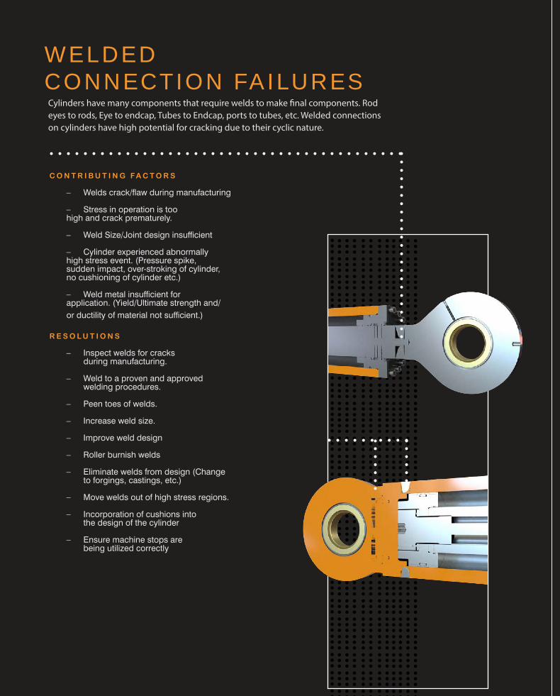
– Welds crack/flaw during manufacturing
– Stress in operation is toohigh and crack prematurely.
– Weld Size/Joint design insufficient
– Cylinder experienced abnormallyhigh stress event. (Pressure spike,sudden impact, over-stroking of cylinder,no cushioning of cylinder etc.)
– Weld metal insufficient forapplication. (Yield/Ultimate strength and/or ductility of material not sufficient.)
R E S O L U T I O N S
– Inspect welds for cracksduring manufacturing.
– Weld to a proven and approvedwelding procedures.
– Peen toes of welds.
– Increase weld size.
– Improve weld design
– Roller burnish welds
– Eliminate welds from design (Changeto forgings, castings, etc.)
– Move welds out of high stress regions.
– Incorporation of cushions intothe design of the cylinder
– Ensure machine stops arebeing utilized correctly
WELDED CONNECTION FAILURESCylinders have many components that require welds to make final components. Rod eyes to rods, Eye to endcap, Tubes to Endcap, ports to tubes, etc. Welded connections on cylinders have high potential for cracking due to their cyclic nature.

WELDED CONNECTION FAILURES
THRE A DED CONNECTION FAILURESHydraulic cylinders use threaded connections in various ways either by bolts or direct thread engagement. Threaded connection failure could include threads stripping, bolts breaking, or components unscrewing from each other.
C O N T R I B U T I N G FA C T O R S
– Stress Cycle too high for the connection design
– Re-use of component too high resulting in failure. (Components fatigued.)
– Pre-load on threads too low.
– Cylinder experienced abnormally high stressevent. (Pressure spike, sudden impact, over-
stroking of cylinder, no cushioning of cylinder etc.)
– Threaded component material insufficientfor application. (Yield/Ultimate strengthand/or ductility of material not sufficient.)
– Vibration causing components to loosen.
R E S O L U T I O N S
– Change connection design to a stronger design, (bolted, different threads, longer threads, increased pre-load, etc.)
– Select threaded component material withsufficient properties for application.
– Track component re-use and setmetrics for replacement.
– Develop method/tools to increase pre-load.
– Investigate machine stops.
– Incorporate cushions into the cylinder design
– Incorporate counter measures for threadedcomponents loosening (Loctite, mechanicallocking means, set screws, etc.)
– Eliminate threaded connections if possible.
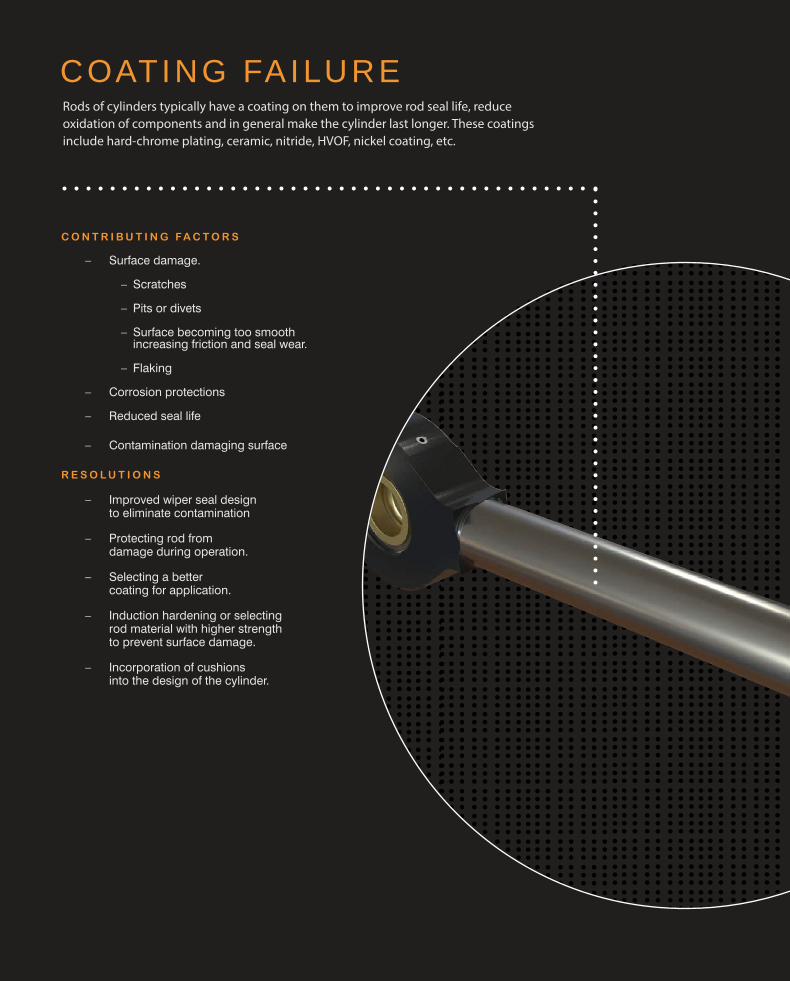
COATING FAILURERods of cylinders typically have a coating on them to improve rod seal life, reduce oxidation of components and in general make the cylinder last longer. These coatings include hard-chrome plating, ceramic, nitride, HVOF, nickel coating, etc.
C O N T R I B U T I N G FA C T O R S
– Surface damage.
– Scratches
– Pits or divets
– Surface becoming too smoothincreasing friction and seal wear.
– Flaking
– Corrosion protections
– Reduced seal life
– Contamination damaging surface
R E S O L U T I O N S
– Improved wiper seal designto eliminate contamination
– Protecting rod fromdamage during operation.
– Selecting a bettercoating for application.
– Induction hardening or selectingrod material with higher strengthto prevent surface damage.
– Incorporation of cushionsinto the design of the cylinder.

COATING FAILURE SE A L FA ILURESSeals allow a cylinder to function. All cylinders produce extending and retracting forces by sealing oil/air/fluid to their respective side of the piston. They also prevent oil/air/fluid from leaking out around the rod and head.
C O N T R I B U T I N G FA C T O R S
– Contamination damaged seals
– Extrusion damage/failure
– Seals damaged from dieseling/explosive decompression
– Heat damaged seals (cylinders operating too hot.)
– Surface finish
R E S O L U T I O N S
– Improved wiper seal design to eliminate contamination (improved wiper, more wipers, trash rings to ingest contamination, etc.)
– Improved machine filtration.
– Improve side loading capability of cylinder by better wear band selection, using brass wear bands, etc.
– Incorporation of cushions into the design of the cylinder to reduce impact and chance of cylinder creating its own contamination
– Sensors to prevent cylinders from over stroking.
– Select higher strength seal material that can handle higher extrusion gaps, higher pressures, etc.
– Rebuild parts that are causing extrusion gaps to be too large.
– Select seal materials that can handle higher temperature.
– Find source of heat generation in the machine hydraulics and eliminate it. (This could include changing valves/fittings that are generating heat)
– Incorporate redundant rod seals to extend life of rod seal system.
– To prevent dieseling the air in the system needs to be removed before pressurizing the oil. This can be done by using bleeder valves or cycling the cylinders several times before allowing the cylinder to be loaded.
– Explosive decompression happens when air/gas permeates into the seal material under pressure and when the pressure drops the gas suddenly escapes taking material with it. Thus, good materials need to be used in these situations.

WE A R COMPONENT FAILURES
C O N T R I B U T I N G FA C T O R S
– Lack of lubrication (poor maintenancepractices, hard to lubricate, harshenvironment that washes lubrication away, etc.)
– Undersized bushing/bearing for application
– Wear component material insufficientfor application. (Yield/Ultimate strengthand/or ductility of material not sufficient.)
R E S O L U T I O N S
– Use of improved spherical bearings
– Maintenance free (no lubrication required)
– Sealed bearing (helps with grease retention & contamination)
– Bearings with improved grease groove designs for ease of lubricating.
– Bearings designed for Impact Applications.
– Sizing bushing/bearing for application.
– Selecting appropriate material and size of bushing for application.
Cylinders typically have wear components that allow them to be attached to the machines. These can include spherical bearings, bushings, etc. These components usually require lubrication for them to operate for long periods of time.
WE A R COMPONENT FAILURES
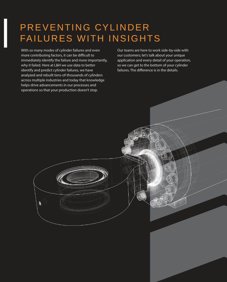
PRE VENTING CYLINDER FAILURES WITH INSIGHTS With so many modes of cylinder failures and even more contributing factors, it can be difficult to immediately identify the failure and more importantly, why it failed. Here at L&H we use data to better identify and predict cylinder failures, we have analyzed and rebuilt tens-of-thousands of cylinders across multiple industries and today that knowledge helps drive advancements in our processes and operations so that your production doesn’t stop.
Our teams are here to work side-by-side with our customers; let’s talk about your unique application and every detail of your operation, so we can get to the bottom of your cylinder failures. The difference is in the details.