faculty of manufacturing engineering - eprints.utem.edu.myeprints.utem.edu.my/18549/1/effect of...
TRANSCRIPT

Faculty of Manufacturing Engineering
EFFECT OF COATING THICKNESS ON THE MICROSTRUCTURE,
MECHANICAL AND WEAR PROPERTIES OF AlTiN COATINGS DEPOSITED USING ARC ION PLATING TECHNIQUE
Kamil Jawad Kadhim
Doctor of Philosophy
2016

EFFECT OF COATING THICKNESS ON THE MICROSTRUCTURE, MECHANICAL AND WEAR PROPERTIES OF AlTiN COATINGS
DEPOSITED USING ARC ION PLATING TECHNIQUE
KAMIL JAWAD KADHIM
A thesis submitted In fulfillment of the requirements for the degree of Doctor of Philosophy
in Manufacturing Engineering
Faculty of Manufacturing Engineering
UNIVERSITI TEKNIKAL MALAYSIA MELAKA
2016

DECLARATION
I declare that this thesis entitled ―Effect of Coating Thickness on The Microstructure,
Mechanical and Wear Properties of AlTiN Coatings Deposited Using Arc Ion Plating
Technique‖ is the result of my own research except as cited in the references. The thesis
has not been accepted for any degree and is not concurrently submitted in candidature of
any other degree.
Signature :
Name : Kamil Jawad Kadhim
Date :

APPROVAL
I hereby declare that I have read this thesis and in my opinion, this thesis is sufficient in
terms of scope and quality for the award of Doctor of Philosophy in Manufacturing
Engineering.
Signature : ........................................................
Supervisor Name : Associate Professor Dr. Md Nizam Bin Abd Rahman
Date : ........................................................

DEDICATION
To my beloved parents, mother, father, and wife, my sons, and my daughters.
Dedicated, to my beloved, brothers and sisters.
Dedicated, to all my family, and my friends.
Thank you for your support and encouragement.
You all are everything for me.
May Allah bless all of us. Insha’Allah.

i
AlTiN coatings were deposited on tungsten carbide insert using Al 0.67 TI0.33 cathodes in cathodic arc plating system. The influence of coating layer thickness on the microstructural, mechanical and wear properties of the coatings was investigated. The AlTiN deposition of hard coatings for tooling applications has many advantages. The main drawback of this technique, however, is the formation of macro particles (MPs) during deposition. The deposited AlTiN coating of various thickness was characterized using X-Ray Diffraction (XRD), scanning electron microscopy (SEM), atomic force microscopy (AFM), Rockwell tester, and ball-on-disc machine, to analyze and quantify the following coating properties: grain size, preferred orientation, atomic elements, thickness, micro hardness, adhesion, surface roughness, and coefficient of friction (COF) of the deposited coatings. Base of this study, the increase in layer thickness was closely related to increase in deposition time. The coating thickness had a significant influence on the width of crater wear. The width of crater wear reduced significantly as the coating thickness increased. However beyond 5.815µm, further increment in coating thickness resulted in increase in crater wear width due to presence of larger macro-particles on the coating surface and reduction of coating hardness. The deposited AlTiN coating also showed a strong preferred orientation of (200) and (111) plane for all coating thickness. The values of various surface roughness measured by AFM was at minimum of 0.07157 µm for the coating having thickness of 2.717 µm whereas; the maximum value of Ra was 0.29647 µm for the coating thickness of 8.760 µm. The highest hardness value was 1939.0 HV for coating thickness of 5.815 µm. Based on adhesion slope technique, AlTiN coatings of 3.089 µm thickness had the best adhesion strength. Correlation study indicated that cutting tools crater wear width has the strongest correlation with the coating atomic percentage ratio of Al/Ti, with coefficient of determination R 2 value of 0.7251. The coating hardness and grain size also indicated some correlation with the crater width wear with R2 values of 0.6051 and 0.5184 respectively.
ABSTRACT

ii
Lapisan AlTiN dideposit pada insert tungsten karbida menggunakan katod Al 0.67 TI 0.33 dengan sistem penyaduran arka. Pengaruh ketebalan lapisan salutan pada mikrostruktur, mekanikal dan sifat-sifat lapisan telah dikaji. Salutan AlTiN untuk aplikasi alat mempunyai banyak kelebihan. Bagaimanapun, kelemahan utama teknik ini adalah pembentukan zarah makro semasa pemendapan. Salutan AlTiN yang didepositkan dengan pelbagai ketebalan dicirikan menggunakan mikroskop elektron pengimbas, daya mikroskop atom, mesin ujian kekerasan, Rockwell penguji, dan bola ke cakera mesin untuk menganalisis dan mengukur sifat-sifat lapisan berikut: saiz butiran, orientasi pilihan, unsur-unsur atom, ketebalan, kekerasan mikro, rekatan, kekasaran permukaan, dan pekali geseran. Keputusan kajian ini menunjukan peningkatan dalam ketebalan lapisan berkait rapat dengan masa pemendapan. Apabila masa pemendapan meningkat begitu juga ketebalan lapisan. Ketebalan salutan mempunyai pengaruh yang besar ke atas lebar kehausan kawah. Lebar kehausan kawah berkurangan dengan ketara apabila ketebalan lapisan meningkat. Namun selepas kira-kira enam mikron, kenaikan berikutnya di dalam ketebalan salutan mengakibatkan peningkatan dalam lebar kehausan kawah. Salutan AlTiN yang didepositkan menunjukkan orientasi krystal yang kuat pada (200) dan (111) untuk semua ketebalan salutan. Nilai kekasaran permukaan diukur oleh daya mikroskop atom yang paling minimum ialah 0.07157μm untuk lapisan yang mempunyai ketebalan 2.717 μm. Nilai maksimum Ra adalah 0.29647μm untuk ketebalan lapisan 8.760 μm. Nilai kekerasan tertinggi ialah 1939.0HV untuk lapisan ketebalan 5,815 μm. Berdasarkan teknik lekatan cerun, AlTiN lapisan ketebalan 3.089μm mempunyai kekuatan lekatan yang terbaik. Kajian korelasi menunjukkan bahawa lebar kehausan kawah alat pemotong mempunyai korelasi yang kuat dengan lapisan nisbah peratusan atom Al / Ti, dengan nilai R2 0.7251. Kekerasan salutan dan bijirin saiz juga menunjukkan korelasi sederhana dengan memakai lebar kawah dengan nilai R2 masing-masing ialah 0.6051 dan 0.5184
ABSTRAK

iii
ACKNOWLEDGEMENT
Alhamdulillah, my deepest gratitude to Allah S.W.T. First, I would like to take this
opportunity to express my sincere acknowledgement to my supervisor Associate Professor
Dr. Md. Nizam Bin Abd Rahman from the Faculty of Manufacturing Engineering,
University Technical Malaysia Melaka (UTeM) for his essential supervision, support and
encouragement towards the completion of this thesis.
I would also like to express my greatest gratitude to Associate Professor Dr. Mohd Rizal
bin Salleh the Dean of Faculty of Manufacturing Engineering University Technical
Malaysia Melaka (UTeM), co-supervisor of this project for his advice and suggestions.
Also my deepest appreciation to all the lecturers and staff of the Faculty of Manufacturing
Engineering. Special thanks are also given to the Ministry of Higher Education the Iraqi
and Technical Education Foundation, now known as the University Middle Euphrates
Technical in Kufa for the support and funding of this project through the fundamental
research grant throughout the study scheme.

iv
TABLE OF CONTENTS
PAGE DECLARATION APPROVAL DEDICATION ABSTRACT i ABSTRAK ii ACKNOWLEDGEMENT iii TABLE OF CONTENTS iv LIST OF TABLES vii LIST OF FIGURES ix LIST OF APPENDICES xiii LIST OF ABBREVIATIONS xiv LIST OF PUBLICATION xvii
CHAPTER
1. INTRODUCTION 1 1.1 Background of study 1 1.2 Introduction 1 1.3 Problem Statement 8 1.4 Research Goals and Objectives 9 1.5 Scope of the Research 9 1.6 Organization of Thesis 10
2. LITERATURE REVIEW 11 2.1 Introduction Introduction 11 2.2 PVD DC Arc system technology PVD DC Arc system technology 12 2.3 Physical Vapor Deposition (PVD) Processes Physical Vapor Deposition (PVD) Processes 15 2.4 Vacuum Deposition (Vacuum Evaporation) 17 2.5 Arc Vapor Deposition System Arc Vapor Deposition System 20 2.6 Ion Plating Ion Plating 20 2.6.1 PVD Process Considerations 21 2.6.2 Deposition of (Al, Ti) N coatings 22 2.6.3 Different Processes of PVD Deposition 23 2.7 Parameters for deposition of coating 24 2.7.1 Effect of cathode composition on PVD deposition Effect of cathode composition on PVD deposition 25 2.7.2 Effect of gas pressure PVD deposition Effect of gas pressure PVD deposition 26 2.7.3 Effect of substrate bias on PVDdeposition Effect of substrate bias on PVDdeposition 30 2.7.4 Phase relationship and crystal structure of (Al, Ti) N Phase relationship and crystal structure of (Al, Ti) N 31 2.7.5 Effect of interlayer/intermediate layer on coating adhesion Effect of interlayer/intermediate layer on coating adhesion 32 2.7.6 Roughness of coated surface Roughness of coated surface 33 2.7.7 Hardness of (Al, Ti) N layer coating Hardness of (Al, Ti) N layer coating 34 2.7.8 Arc vaporization 35 2.7.9 Crystal structure 36 2.7.10 Adhesion Properties analysis 38 2.7.11 Tribological coatings 39 2.7.12 Friction and wear 40
v
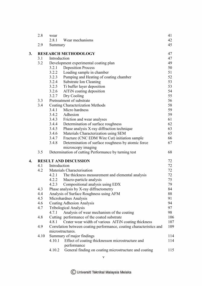
2.8 wear
41
2.8.1 Wear mechanisms 42 2.9 Summary 45
3. RESEARCH METHODOLOGY 47 3.1 Introduction 47 3.2 Development experimental coating plan 49 3.2.1 Deposition Process 50 3.2.2 Loading sample in chamber 51 3.2.3 Pumping and Heating of coating chamber 52 3.2.4 Substrate Ion Cleaning 53 3.2.5 Ti buffer layer deposition 53 3.2.6 AlTiN coating deposition 54 3.2.7 Dry Cooling 55 3.3 Pretreatment of substrate 56 3.4 Coating Characterization Methods 58 3.4.1 Micro hardness 59 3.4.2 Adhesion 59 3.4.3 Friction and wear analyses 61 3.4.4 Determination of surface roughness 62 3.4.5 Phase analysis X-ray diffraction technique 63 3.4.6 Materials Characterization using SEM 65 3.4.7 Fracture (CNC EDM Wire Cut) initiation sample 66
3.4.8
Determination of surface roughness by atomic force microscopy imaging
67
3.5 Determination of cutting Performance by turning test 68
4. RESULT AND DISCUSSION 72 4.1 Introduction 72 4.2 Materials Characterisation 72 4.2.1 The thickness measurement and elemental analysis 72
4.2.2 Macro-particle analysis 75 4.2.3 Compositional analysis using EDX 79 4.3 Phase analysis by X-ray diffractometry 84 4.4 Analysis of Surface Roughness using AFM 88
4.5 Microhardnes Analysis 91 4.6 Coating Adhesion Analysis 94 4.7 Tribological Analysis 97 4.7.1 Analysis of wear mechanism of the coating 98
4.8 Cutting performance of the coated substrate 106 4.8.1 Crater wear width of various AlTiN coating thickness 107
4.9
Correlation between coating performance, coating characteristics and microstructures.
109
4.10 Summary of major findings 114 4.10.1 Effect of coating thicknesson microstructure and
performance 114
4.10.2 General finding on coating microstructure and coating 115

vi
performance performance
5. CONCLUSION AND RECOMMENDATION 117
5.1 Conclusions 117 5.2 New contributions to body of knowledge 118 5.3 Future work and recommendation 118
REFERENCES 120 APPENDIX A 131 APPENDIX B 137 APPENDIX C 142 APPENDIX D 147 APPENDIX E 151 APPENDIX F 161

vii
LIST OF TABLES
TABLE TITLE PAGE
2.1 Summary of study done on thin film coatings deposited using
various PVD techniques
14
2.2 Characterization techniques by several researchers 37
2.3 Rockwell-C characterization techniques performed by several
researchers using slopes of indentation load versus crack diameter
39
2.4 Several methods for measurement crater wear 42
3.1 Ion cleaning parameters 53
3.2 Buffer layer parameters 54
3.3 Main layer parameters 54
3.4 Deposition parameters 55
3.5 Cleaning Procedure. 56
3.6 The characterization equipment used in the respective intended
coating Characteristic/performance data to be collected.
58
3.7 List of tribological parameters during Ball-on-Disc test 62
3.8 SEM/EDX parameters setting 62
3.9 XRD Settings 64
3.10 SEM/EDX parameters setting 65
3.11 Duplex 2205 stainless steel chemical compositions. 68
3.12 Summary of single point turning conditions 70
4.1 Main process AlTiN of coatings deposition 74
4.2 Micro-particle measurement at AlTiN coating 77
4.3 Analysis of as-deposited AlTiN coatings 81
4.4 Deposition time and thickness with Al/Ti ratio at AlTiN coating 82
4.5 XRD crystallographic data for various coating thickness 87
4.6 AlTiN coating characteristics and microstructure data with varying 88
viii
layer
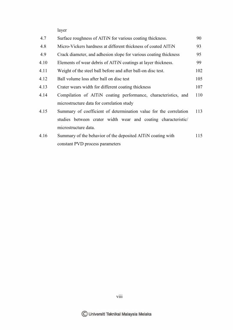
4.7 Surface roughness of AlTiN for various coating thickness. 90
4.8 Micro-Vickers hardness at different thickness of coated AlTiN 93
4.9 Crack diameter, and adhesion slope for various coating thickness 95
4.10 Elements of wear debris of AlTiN coatings at layer thickness. 99
4.11 Weight of the steel ball before and after ball-on disc test. 102
4.12 Ball volume loss after ball on disc test 105
4.13 Crater wears width for different coating thickness 107
4.14 Compilation of AlTiN coating performance, characteristics, and
microstructure data for correlation study
110
4.15 Summary of coefficient of determination value for the correlation
studies between crater width wear and coating characteristic/
microstructure data.
113
4.16 Summary of the behavior of the deposited AlTiN coating with
constant PVD process parameters
115

ix
LIST OF FIGURES
FIGURES TITLE PAGE
2.1 Several PVD techniques are available for deposition of hard
coatings
13
2.2 Gas flow regimes vacuum ranges (https://www.chalmers.se/.../lecture_6.../"vacuum"/., Lecture handouts Chalmers University of Technology).
16
2.3 PVD processing techniques: Sputter deposition in a vacuum and ion
plating with an arc vaporization source (Bunshah, 1994.; Kerdel et
al., 2014).
17
2.4 Typical microstructure of PVD (Al, Ti) N coatings deposited by: arc
evaporation (Paldey and Dee. 2003; Arslan et al. (2013).
27
2.5 Improvement of surface morphology in a filtered cathodic arc
system; Arndt and Kacsich (2003).
28
2.6 Schematic representation of the influence of substrate temperature
and argon pressure on the microstructure of metal coatings
deposited, (Anders and Berkeley 2007; Zhu 2013)
29
2.7 (a) Ternary phase diagram and (b) TiN lattice parameter. Paldey and
Dee, (2003).
32
2.8 The hardness and Young’s Modulus as a function of the Al
concentration in the (Ti1- x Al x) N films (PalDey and Deev, 2003).
35
2.9 (a) XRD patterns obtained on CrAlTiN and (b) carbon-doped
CrAlTiCN coating (Wenwen Wu. 2010).
36
2.10 (a): The lateral crack diameter vs. applied load for TiAlN films with
various Ti fractions. (b): The pictures of crack circle after a 150 kgf
indentation test (Wu et al. 2000).
39
2.11 Historical development of tribological coatings and solid films.
Source: Ref; W. Wu (2010).
40

x
2.12 Crater and crater wear measurement method for tool insert in single
point turning Operation based on ISO 3685:1993(E) standards.
44
3.1 Overall approach of PVD process design with experimental studies 47
3.2 Methodology of PVD process, ARC evaporation system
development.
48
3.3 PVD ARC system technology made by J&L technology 49
3.4 Sumitomo SPGN120308S cutting tool dimension 50
3.5 Tungsten carbide cutting tool insert commercially made by
Sumitomo (cutting tool tungsten carbide).
50
3.6 Process progress deposition of coating 51
3.7 Loading sample in holder jig on the chamber 52
3.8 Schematic diagram of the arc ion plating system 55
3.9 The cutting insert was cleaned by ultrasonic with a detergent bath
for
different mixed detergent and time
57
3.10 (a) and (b): Vickers micro hardness testing machine Vickers tester,
(VLPAK-2000 Mitutoyo microwizhard) was performed on the
coatings.
59
3.11 Adhesion slope measurement plot at three different loads (a), and
Crack diameter measurement using optical microscope (b).
60
3.12 OMAG 250-3302MRS Rockwell indentation tester. 60
3.13 Ball-on-Disc tester 61
3.14 Surftest SJ-310 contact stylus profiler by MITUTOYO 63
3.15 Bruker D-8 XRD apparatus with GIA capability as shown (a), (b)
and (c).
65
3.16 Scanning electron microscopy imaging with Signals produced when
electron beam interact with the sample.
66
3.17 CNC EDM Wire Cut Machine and Vise 67
3. 18 AFM Shimadzu model SPM-9500J2 apparatus 67
3.19 Precision lathes model CNC Machine 69
3.20 Standard IS0 3685-1993 71
4.1 Brittle fracture micrograph and EDX spectrum of AlTiN, thickness 74

xi
2.717to 8.760 µm.
4.2 Correlation between coating thickness and deposition time. 75
4.3 Microparticle of AlTiN coatings with different thickness layer: (a)
2.717µm , (b) 3.089µm, (c) 3.912µm , (d) 5.815µm ,(e) 8.760µm
(mag = 10.000 kx).
76
4.4 Surface SEM micrographs of AlTiN coatings with different layer
thickness: (a) 2.717; (b) 3.089; (c) 3.912; (d) 5.815; (e) 8.760 um
with different deposition time: 45; 80;100;120;135 mins (mag =
1.000 kx).
78
4.5 Correlation between thickness and AlTiN coating macro-particle. 79
4.6 EDX analysis of the deposited AlTiN coating with various
thicknesses.
81
4.7 Thickness of AlTiN layer coatings with different Al/Ti ratio (%). 82
4.8 Ti/Al and Nitrogen atom ratio of AlTiN layer coatings with different
thickness layers.
83
4.9 Deposition time and thickness with Al/Ti ratio at AlTiN coating. 84
4.10 Correlation between coating thickness on crystallographic preferred
orientation
85
4.11 XRD patterns of AlTiN layer coatings with different layer
thicknesses and tungsten carbide substrate.
86
4.12 Variation of deposition time and Grain size. 88
4.13 Three-dimensional AFM image of tungsten carbide; a =2.717 µm;
b=3.089µm; c =3.912 µm; d =5.815 µm; e =8.760818 µm surface
various thicknesses with layer (AlTiN) coating, caption 10 x 10µm.
89
4.14 Variation in graph between average roughness and coating thickness
of AlTiN-coated tungsten carbide insert.
91
4.15 Hardness of ATilN coating load 50g and indenter tip. Micro-
hardness indentation test
92
4.16 Hardness of AlTiN layer coatings with different thickness and
deposition time.
94
4.17 Thickness vs. Adhesion slope 95

xii
4.18 Adhesion Load of AlTiN coatings with different layers thickness:
(a) 2.717µm, (b) 3.089 µm, (c) 3.912 µm, (d) 5.815 µm,(e) 8.7608
µm. (Load HRA= 588, HRD = 980, HRC = 1470).
96
4.19 Coefficient of friction of AlTiN, different layers thickness coatings
as shown in hardness.
97
4.20 Coefficient of friction of AlTiN, different layers thickness coatings 98
4.21 Surface morphologies of the wear track on (a) Thickness: 2.717µm,
(b) Thickness: 2.089µm, (c) Thickness 3.912µm, (d) Thickness:
5.815µm, and (e) Thickness: 8.760µm.
101
4. 22 Surface morphologies of the wear track as well as the EDX
spectra of the adhesive debris on (a),(b),(c),(d),and (e). AlTIN
coatings.
103
4.23 Profile of cross sections of the wear tracks of AlTiN coating after
Pin-on-disc testing(a)-width, (b)- depth, (r3)- radius of sliding track
(a),(b),(c), (d), and (e), (thickness various).
106
4.24 Variations of crater wear width with thickness layer 108
4.25 Variations of crater wear width with Al/Ti ratio 108
4.26 Correlation between crater width wear and I111/1200 ratio 110
4.27 Correlation between crater width wear and atomic percentage ratio
of aluminum and titanium of AlTiN coating
111
4.28 Correlation between crater widths wear and grain size of AlTiN
coating
111
4.29 Correlation between crater width wear and roughness of AlTiN
coating
112
4.30 Correlation between crater width wear and TiAlN coating hardness 112
xiii
LIST OF APPENDICES
APPENDIX
TITLE PAGE
A SEM/ DATA macro-particle 131
B XRD DATA 137
C Surface Roughness 142
D Adhesion of AlTiN layers coating; Rockwell adhesion
indentation test (Mercedes test).
147
E Tribological tests 151
F The wear rate (Tribological properties) and maximal depth
of wear tracks of the AlTiN layer Coatings at different
thickness layers. Measured using optical Scanning Microscopy.
161

xiv
LIST OF ABBREVIATIONS
Å Angstrom refer to in terms of measurement (1x10⁻¹⁰ meter or 0.1 nm)
function
AFM Atomic Force Microscopy
Al Aluminum
AlTiN Aluminium Titanium Nitride
Amorphous Phases are important constituents of thin films, which are solid layers of a
few nm to some tens of µm thickness deposited upon a substrate.
Anticorrosion Refers to the protection of metal surfaces from corroding in high-risk
(corrosive) environments. When metallic materials are put into corrosive
environments, they tend to have chemical reactions with the air and/or
water. The effects of corrosion become evident on the surfaces of these
materials. Therefore, metal equipment lacking any preventive (anti-
corrosive) measures, may become rusted both inside and out, depending
upon atmospheric conditions and how much of that equipment is exposed
to the air. There are a number of methods for preventing corrosion,
especially in marine applications.
Ar Argon
C Carbon
CNC Computer Numerical Controll
Co Cobalt
COF Coefficient of Friction
Cr Chromium
CVD Chemical Vapour Deposition
DC Direct Current
DI water Purified water is water that is mechanically filtered or processed to be

xv
cleaned for consumption. Distilled water and deionized (DI) water have
been the most common forms of purified water.
DLC Diamond- Like Carbon
EHT Extra high tension, or high voltage
FCC Face Centre Cubic
GPa Giga-Pascal (1GPa= 1,000,000,000Pa)
HT 1170 Deconex is a liquid, mildly alkaline cleaning concentrate used in
ultrasonic cleaning systems, with high surfactant content and high
degreasing power.
HT 1233 Deconex is a mildly alkaline liquid, cleaning concentrate for the final
cleaning step before rinsing and drying, for carbide and HSS parts. It is
suitable for both pre-cleaning and final cleaning. However it is very
frequently used in the final cleaning step prior to coating.
HT 1401 Deconex is a highly alkaline liquid cleaning concentrate for removing
machining oils, corrosion proofing oils. Deconex HT 1401 is primarily
used with ultrasonic cleaners during the pre-cleaning step. For use in
soaking baths and ultrasonic cleaning systems, especially on corrosion-
sensitive metals such as steel, HSS and carbides.
HV Hardness Vickers Pyramid Number
ICSD (Inorganic Crystal Structure Database)
MFC Mass Flow Controller
MPs Macro-particles
N2 Nitrogen
Ni Nickel
PVD Physical Vapour Deposition
Ra Surface roughness SCCM Is referring of standard cubic centimeters per minute indicating cc/min at a
standard temperature and pressure. A flow measurement term indicating
cc/min at a standard temperature and pressure.
SEM Scanning Electron Microscopy
xvi
Ti Titanium
TiN Titanium Nitride
WC Tungsten Carbide
XRD X- ray diffraction
Y Yttrium
Zr Zirconium

xvii
LIST OF PUBLICATION
Conference Kamil Jawad Kadhim, Md Nizam Abd Rahman, and Mohd Rizal Salleh, 2012. Effect of Coating Machining Process on Crater Wear. Proceeding of International Conference on Design and Concurrent Engineering (iDECON 2012), 15-16 October. Melaka: Universiti Teknikal Malaysia Melaka (UTeM). Kamil Jawad Kadhim, Md Nizam Abd Rahman, Mohd Rizal Salleh and Khairul Izani Mohd Zukee, 2014. Effect of Layer Thickness on the Properties of Multilayer Ti/AlTiN Coatings by Arc Ion Plating System. Proceeding of International Conference on Design and Concurrent Engineering (iDECON 2014), 22-23 September. Melaka: Universiti Teknikal Malaysia Melaka (UTeM). Kamil Jawad Kadhim, Md Nizam Abd Rahman, Mohd Rizal Salleh and Khairul Izani Mohd Zukee, 2014. Effect of Thickness on the Structural and Surface Roughness of TiAlN Films. International Symposium on Research in Innovation and Sustainability 2014 (ISoRIS’14), 15-16 October. Melaka: Universiti Teknikal Malaysia Melaka (UTeM). Journal Kamil Jawad Kadhim, Md Nizam Abd Rahman, Mohd Rizal Salleh and Khairul Izani Bin Mohd Zukee, 2014. Effect of Thickness on the Structural and Surface Roughness of AlTiN Films. Sci. Int. (Lahore), 26(4), pp. 1431-1435. Kamil Jawad Kadhim, Md Nizam Abd Rahman, Mohd Rizal Salleh, Khairul Izani Mohd Zukee."Effects of Layer Thickness on the Microstructures of TiN/AlTiN Multilayer Coatings", Applied Mechanics and Materials Vol. 761 (2015) pp 417-420 Kamil Jawad Kadhim, Md Nizam Abd Rahman, and Mohd Rizal Salleh, 2014. Effect of Machining Process using TiN/AlTiN Multilayer Coating on Crater Wear and Tribological Properties. International Review on Modelling and Simulations (I.RE.MO.S.), Vol. xx, No. x. (Under review) Kamil Jawad Kadhim, Md Nizam Abd Rahman, and Mohd Rizal Salleh, 2014. Friction and Wear Properties of TiN/TiAlN Multilayer Coatings Deposited By Arc Ion Plating. Journal of Theoretical and Applied Information Technology XXst Month 201x. Vol. x No.x © 2005 - 2012 JATIT & LLS. All rights reserved. (Under review).

1
1.1 Background of study
Single, multi- layers, nitride coatings, are widely used to extend the lifetime of
machine parts. The properties of nitride coating improve adhesion and hardness which
minimize wear rate and coefficient of friction. This generates significant improvement in
performance and prolonged life of the coated tools (Aihua et al., 2012; Biksa et al., 2010).
This research project is part of a program funded by the Iraqi Government to
enable their oil companies to find appropriate solutions for the repair of oil drilling
equipment. Since nitride coatings have proven to be superior in terms of performance, this
research project was geared towards the study of the characteristics and performance of
AlTiN coating on tungsten carbide (WC) inserts in cutting duplex stainless steel which was
widely used material in oil drilling industry. The AlTiN coating was deposited using arc
ion plating technique on to WC insert.
1.2 Introduction
Coating, technique known as physical vapor deposition (PVD), is a process which
can be carried out by several techniques such as magnetron sputtering, ion beam assisted
deposition, arc evaporation and pulsed laser deposition (PLD), has been successfully used
to protect surfaces of mechanical components working under high wear loads during the
last five decades (Abu-Shgair et al., 2010)
The coating of thin Ti and Al could be performed as monolayer (Jakubéczyová et
al., 2012; Kottfer et al., 2013; Abd Rahman, 2009; Birol et al., 2010 ; Podgursky et al.,
2011) multilayer (Ramadoss et al., 2013; Jianxin and Aihua, 2013), and gradient layers
CHAPTER 1
CHAPTER 1
INTRODUCTION

2
(Chang and Wang, 2007). The thin Ti coating in particular is widely used for its good
properties of improving adherence, hardness, reducing wear rate and coefficient of friction
(Thornton et al., 1994; Grips et al., 2006; William and Retwisch, 2010; Vamsi- Krishna et
al., 2010). A recent work by (Yong-Qiang et al., 2011) suggested that TiN/TiAlN and
TiN/AlTiN multilayer coatings deposited on cutting tools could improve mechanical and
corrosion resistance. It has been shown that AlTiN coating has better mechanical
properties compared to TiN due to the inclusion of aluminum atoms in TiN crystalline
structure which results in increasing oxidation resistance by formation of the stable ternary
material AlTiN (Verma et al., 2012; Cselle et al., 2009).
Recently, a new coating technology known as pulsed bias arc ion plating (PBAIP)
which has advantages over other technologies due to its lower processing temperature
requirement, lower residual stress, better grain refinement and particle purification
(Soediono 1989; Bunshah, 1994; PalDey et al., 2003). PBAIP also provides the ideal
conditions for the deposition of a multilayer film with excellent performance.
The process of ion plating is normally performed by using concurrent or periodic
bombardment of the substrate and deposited film prior to deposition which is described as
preliminary process called sputtering in order to prepare the substrate (Wei and Gong,
2011; Lackner et al., 2013). It is stated that (Ti, Al) N coating enhances wear and oxidation
resistance of tools as, (Arslan et al., 2013; Yıldız et al., 2013).
Titanium Aluminum Nitride (TiAlN), known also as AlTiN, depends on the
compositions of Ti and Al and is suitable for coating cutting tools for machining hard to
cut materials because the coating can withstand extreme environments such as high
temperature and high pressure condition. These properties made TiAIN suitable for use in
dry machining and high-speed milling and turning where heat is generated (Chou et al.,
2002; Siow et al. 2013; Li et al., 2013; Feng et al., 2013).When properly applied, it