faculty of engineering and sustainable...
TRANSCRIPT
FACULTY OF ENGINEERING AND SUSTAINABLE DEVELOPMENT .
Performance of antennas in an industrial environment
Javier Pardo Garcia
14/6/2012
Email: [email protected]
Bachelor Thesis in Electronics
Examiner: Nicklas Rothpfeffer
Supervisor: Mr Sathyaveer Prasad


Javier Pardo Garcia Performance of antennas in an industrial environment
1
Abstract
The industry is constantly growing and thus needs new applications for the future. The
problems for these technologies are the main worries for the developers because in an
industrial environment there are interference factors, which make use of other kind of
technologies and antennas.
Generally, the technologies currently used in an industry are not optimized for industrial
environments although some standard organizations are working to develop future standards
(ETSI). Special structures, which are used in industries, include different materials; these
materials produce changes in the behavior of transmitters and receivers. Absorbent materials
can reduce this problem and reduce propagation.
The main goal of this project is to analyze different antennas using the software Savant, to
choose the best one in an industrial environment. The analysis of antennas will simulate the
usage of different antennas in an industrial environment in the frequency range of (300 MHz-
3 GHz). Further, different coats will be used to find out which one is the better one
concerning the coat. By using the software Savant we will design the coating to analyze it.
We will use two different kinds of coat Metal (PEC) and Single layer dielectric.Once we
found the result we will look in the range of frequency 2.4 GHz and we will select the best
one for calculating the losses of the difference between total field of Metal PEC and Singer
layer dielectric.
The study showed that the best antennas for industrial environments are the dipole and
monopole ones, because both of them have low losses in this hostile environment. The
sections provided during the study intend to guide the research into the important aspects that
revolve around the experiment.
Javier Pardo Garcia Performance of antennas in an industrial environment
2
Acknowledgments
In the following I like to thank Dr. Jose Chilo and Mr.Sathyaveer Prasad, who guided me
towards my final thesis and gave me very helpful instructions due to their knowledge. Further,
I am thankful to the University of Gävle for giving me the opportunity to write my final thesis
and thus being able to graduate.
Sincere thanks and a special attention is given to my father, who, besides my mother, has
been the most important and inspiring person for me, as he tragically passed away five
months ago. He would have loved to read my thesis and been very proud of me.
Javier Pardo Garcia Performance of antennas in an industrial environment
3
Table of contents
Abstract ................................................................................................................................................... 1
Acknowlodgments ……………………………………………………………………………………...2
Table of contents ..................................................................................................................................... 3
1 Introduction ....................................................................................................................................... 4
1.1 Background ……………………………………………………………………………………...4
1.2 Industrial Environment ………………………………………………………………………….4
1.3 The Aims ………………………………………………………………………………………..5
1.4 The procedure of the thesis ……………………………………………………………………...5
1.5 The limitations …………………………………………………………………………………..6
2 Theory ............................................................................................................................................... 7
2.1 Main concepts: .............................................................................................................................. 7
2.2 Software capabilities ……………………………………………………………………………..7
2.3 Material Coatings . ........................................................................................................................ 8
2.4 Antennas types …………………………………………………………………………………...9
3 Process and results .......................................................................................................................... 13
4 Discussion and conclusion .............................................................................................................. 19
References ............................................................................................................................................. 20
Calculation of the losses ....................................................................................................................... A1
Dessing of the cad with Rhino…...……………………………………………………………………B1

Javier Pardo Garcia Performance of antennas in an industrial environment
4
1 Introduction
1.1 Background
The industry is constantly growing and the new wireless technologies are in need of new
applications for the future. These technologies are of great importance and affect the future.
An industry provides increased flexibility and productivity for this technology. However, the
demand of technologies will arise within these harsh environments, which may contain
different kinds of materials.
Generally the technologies currently used in an industry are not optimized for industrial
environments, although some standard organizations are working to develop future standards
(ETSI).
The industry has special building structures that include a high amount of different materials.
This produces changes in the behavior of the transmitting channels, whose troubles can
disturb the communication. Therefore some industrial environments present opposite
properties as absorbent material and can considerably reduce the propagation. [1].
Moreover the industrial environment has lower contaminants than the other like marine
ambient but the corrosion is higher [6].
Some common incident in industrial environment could be materials and distance of the
technologies.
1.2 Industrial Environment
The industrial environment which we are going to analyze is situated within an industrial
building that has different materials and we can find different interferences from many
devices that are working in the same time and we can’t determinate it.

Javier Pardo Garcia Performance of antennas in an industrial environment
5
Nowadays it is really important to get good connections in this hostile ambient in a
determinate range of frequency where the WLAN and Bluetooth technologies can develop
applications to improve the connections in this ambient.
1.3 The Aims
The goal of the thesis, it is to analyze the different antennas in an industrial environment and
suggest the best one for this ambient.
To be able to perform the analysis of the antennas, we will simulate an industrial environment
using different antennas in the frequency range of (300 MHz -3 GHz). It is possible to use
several kinds of antennas to analyze the environment with different coats to choose.
Using the software Savant we will design the coats to analyze it. We will use two different
kinds of coat Metal (PEC) and Single layer dielectric.
Once we obtained the result we will look in a single point and we will take the best one to
calculate the losses and also we will choose the best one depending on the polarization.
The range of frequency is used for WLAN and Bluetooth and this kind of technologies
provides better performance.
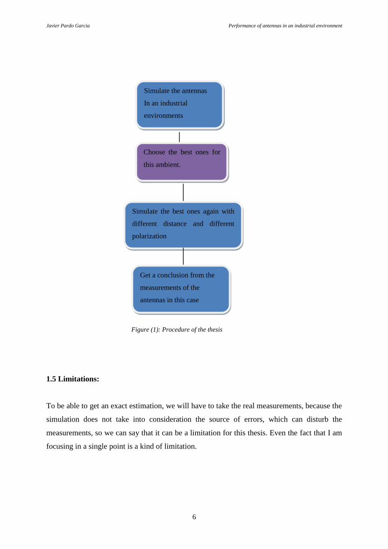
1.4 The procedure about the thesis
The procedure Figure (1) of this thesis is realized in Savant by simulating an industrial
environment. I therefore need to create an industrial environment with different materials to
simulate with the antennas.
Javier Pardo Garcia Performance of antennas in an industrial environment
6
Figure (1): Procedure of the thesis
1.5 Limitations:
To be able to get an exact estimation, we will have to take the real measurements, because the
simulation does not take into consideration the source of errors, which can disturb the
measurements, so we can say that it can be a limitation for this thesis. Even the fact that I am
focusing in a single point is a kind of limitation.
Choose the best ones for
this ambient.
Simulate the best ones again with
different distance and different
polarization
Get a conclusion from the
measurements of the
antennas in this case
Simulate the antennas
In an industrial
environments

Javier Pardo Garcia Performance of antennas in an industrial environment
7
2 Theory
The theory section explains the main concepts and methodology implemented in Savant and
the main reference [2] for this chapter. This section intends to provide key concepts that will
be used throughout the study [3].
2.1 Main concepts:
Far-field is the region of the field of an antenna where the angular field distribution is
essentially independent of the distance from the antenna.
The E and H plane patterns are defined as: the plane E contains the electric-field vector (and
the direction of maximum radiation) and the plane H as the plane that contains the magnetic-
field (and the direction of maximum radiation.)
Incident Field is the field that arrives to the objet radiated by Tx antenna in free space (as if
the scattering geometry was not there).
Scattered Field is the field, which doesn’t radiate by Tx in and free space.
Total Field - field generated by Tx antenna in the presence of the scattering geometry
(coherent sum of incident and scattered field)
Power of antenna: the power of the antenna is calculating by Power= 1/ (distance)2

Javier Pardo Garcia Performance of antennas in an industrial environment
8
Friss Antennas Equation: the Friis equation is used to know the power received from one
antenna (G1) when we are transmitting from another antenna (G2) with a distance (R) given
by Figure (2.1).
antenna1 antenna 2
distance R
Figure (2.1)
2.2 Software Capabilities:
Savant is simulation software for predicting the performance of antennas in an environment
such as industrial environments, aircraft, buildings and other platforms. Savant can predict :
Far field radiation pattern, Scattered field incident field, cosite coupling/ isolation between
antennas mounted on a common platform. Source antenna the Tx launch rays assigned a
vector field according with the polarization. Savant can give us the result in a table
(Appendix A).
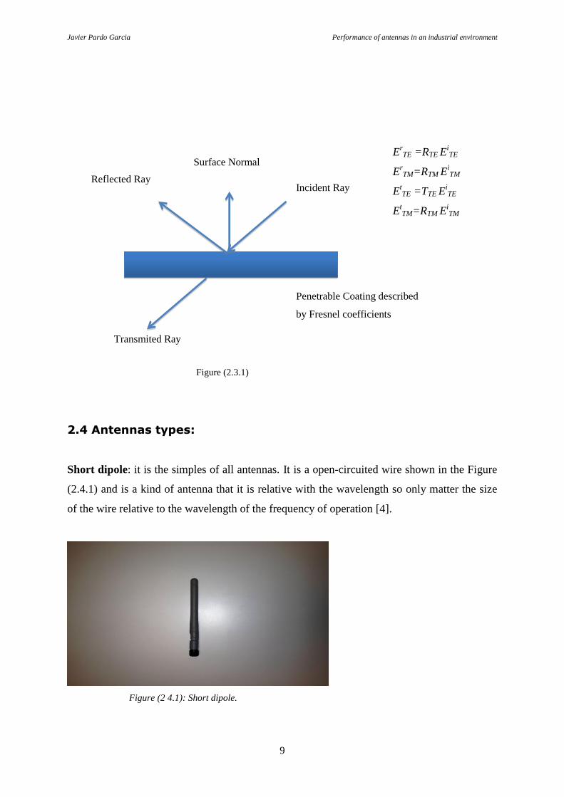
2.3 Material Coatings it is based on Fresnel reflection [5].
The coatings is the materials that one choices for a cad. Savant provides one with two
possibilities; Single layer dielectric, Perfect electric conductor (PEC)
The performance the analysis the ray hits the surface and discomposed into transverse-electric
(TE) and transverse-magnetic (TM) polarizations depending of the material coating assigned
to the surface and the incident. The coefficients are obtained from the table 2.3.1
Javier Pardo Garcia Performance of antennas in an industrial environment
9
Figure (2.3.1)
2.4 Antennas types:
Short dipole: it is the simples of all antennas. It is a open-circuited wire shown in the Figure
(2.4.1) and is a kind of antenna that it is relative with the wavelength so only matter the size
of the wire relative to the wavelength of the frequency of operation [4].
Figure (2 4.1): Short dipole.
Incident Ray Reflected Ray
Transmited Ray
Surface Normal
Penetrable Coating described
by Fresnel coefficients
ErTE =RTE E
iTE
ErTM=RTM E
iTM
EtTE =TTE E
iTE
EtTM=RTM E
iTM
Javier Pardo Garcia Performance of antennas in an industrial environment
10
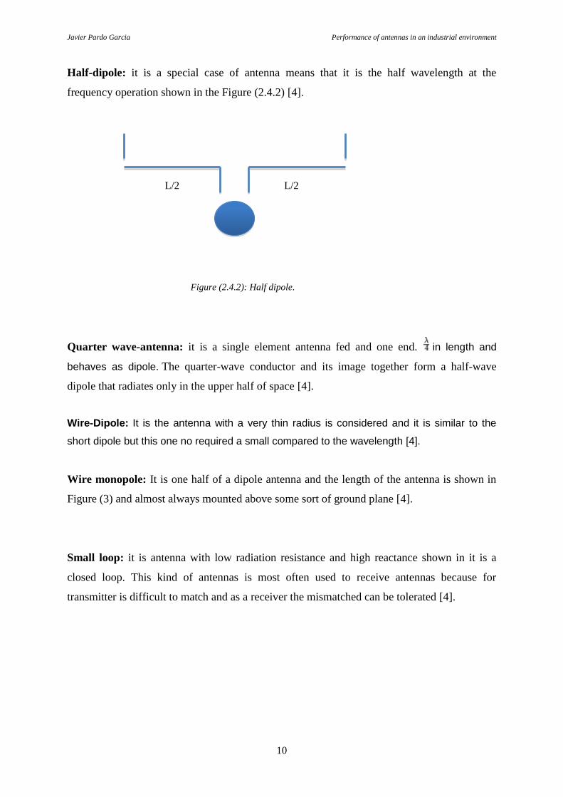
Half-dipole: it is a special case of antenna means that it is the half wavelength at the
frequency operation shown in the Figure (2.4.2) [4].
Figure (2.4.2): Half dipole.
Quarter wave-antenna: it is a single element antenna fed and one end. in length and
behaves as dipole. The quarter-wave conductor and its image together form a half-wave
dipole that radiates only in the upper half of space [4].
Wire-Dipole: It is the antenna with a very thin radius is considered and it is similar to the
short dipole but this one no required a small compared to the wavelength [4].
Wire monopole: It is one half of a dipole antenna and the length of the antenna is shown in
Figure (3) and almost always mounted above some sort of ground plane [4].
Small loop: it is antenna with low radiation resistance and high reactance shown in it is a
closed loop. This kind of antennas is most often used to receive antennas because for
transmitter is difficult to match and as a receiver the mismatched can be tolerated [4].
L/2 L/2
Javier Pardo Garcia Performance of antennas in an industrial environment
11
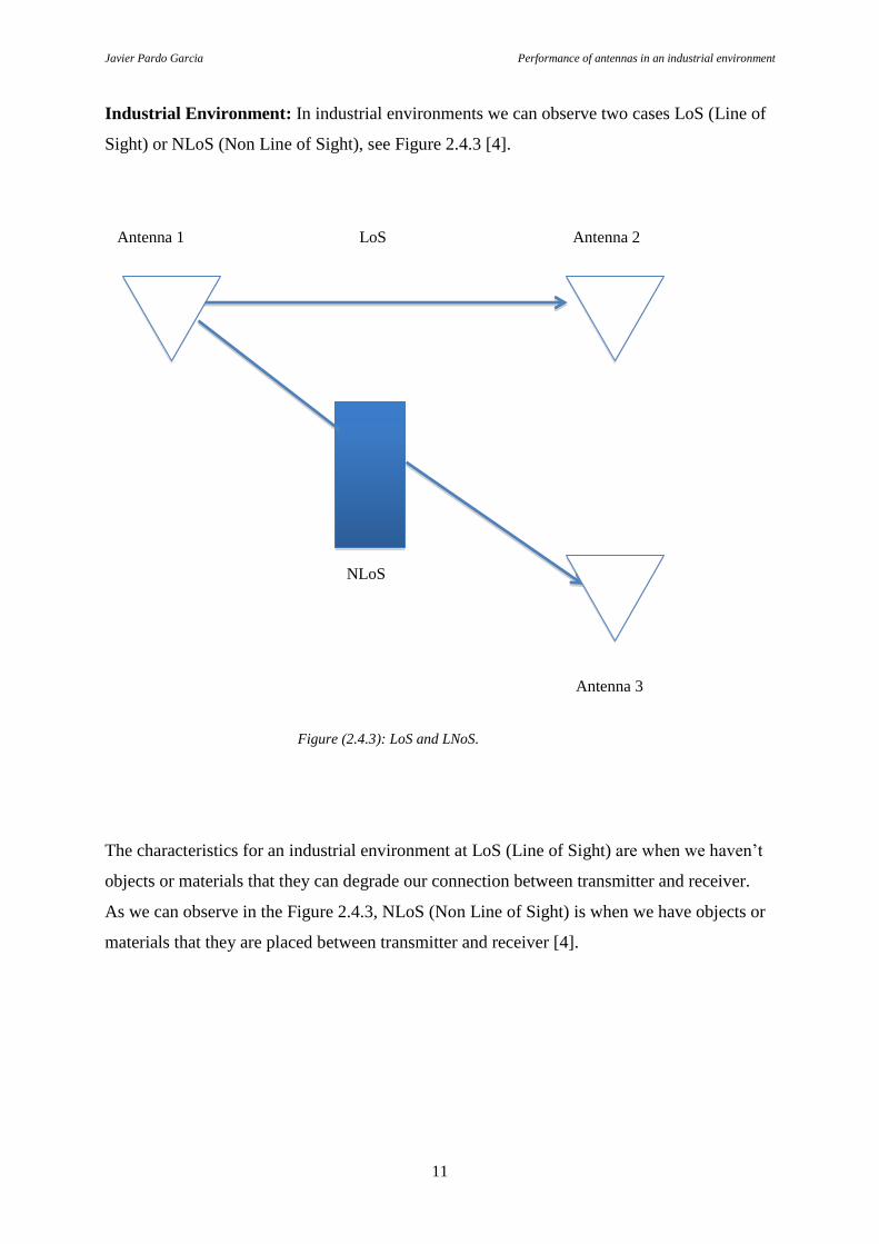
Industrial Environment: In industrial environments we can observe two cases LoS (Line of
Sight) or NLoS (Non Line of Sight), see Figure 2.4.3 [4].
Antenna 1 LoS Antenna 2
NLoS
Antenna 3
Figure (2.4.3): LoS and LNoS.
The characteristics for an industrial environment at LoS (Line of Sight) are when we haven’t
objects or materials that they can degrade our connection between transmitter and receiver.
As we can observe in the Figure 2.4.3, NLoS (Non Line of Sight) is when we have objects or
materials that they are placed between transmitter and receiver [4].

Javier Pardo Garcia Performance of antennas in an industrial environment
12
In indoor industrial environment we can considerer several kind of situations depending on
the dimensions and quantity of metallic objects, high, medium and low reflective. [1]
High reflective can be found at halls with a big amount of metallic structural materials and
objects composed by metal, on other hand the interferences of the machinery is another factor
that degrade our connections.
Medium reflective is the typical industrial building, the structure walls and the ceiling are
made with metallic materials. In this kind of environments there are metallic objects but its
density is lower than the high reflective.
The environments with Low reflective don’t have just reflective and there are absorbent
objects.

Javier Pardo Garcia Performance of antennas in an industrial environment
13
3 Process and results
In this section we are going to use a determinate range of frequency (300 MHz – 3 GHz) and
the six antennas that work in the same range in an industrial environment. The industrial
environment that we are going to consider is an industrial building with different materials.
The first process will be to analyze all antennas with the coat Metal (PEC) and Single layer
dielectric by looking the main factor of antennas (Power dB) in an industrial environment.
First of all we have to charge the building and put the antennas in the same distance to get the
best one for this ambient Figure (3.1).
The Figure is created by the software Rhino appendix B1.
Figure (3.1): It is our environment industrial created with Rhino appendix B.
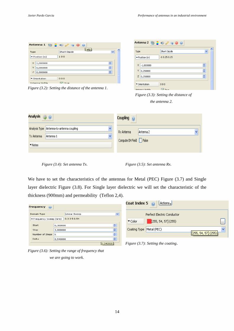
After of load the cad we have to set the parameters of distance Figure (3.2) and Figure (3.3)
for each antenna and the kind of the antenna for our analysis. We can use six different kinds
of antennas before mentioned in theory chapter.
Set the antenna as transmitter Figure (3.4) and the other one as receiver Figure (3.5) and set
the range frequency and the distance that we going to work our case (300Mhz – 3Ghz) Figure
(3.6).
Javier Pardo Garcia Performance of antennas in an industrial environment
14
Figure (3.2): Setting the distance of the antenna 1.
Figure (3.3): Setting the distance of
the antenna 2.
Figure (3.4): Set antenna Tx. Figure (3.5): Set antenna Rx.
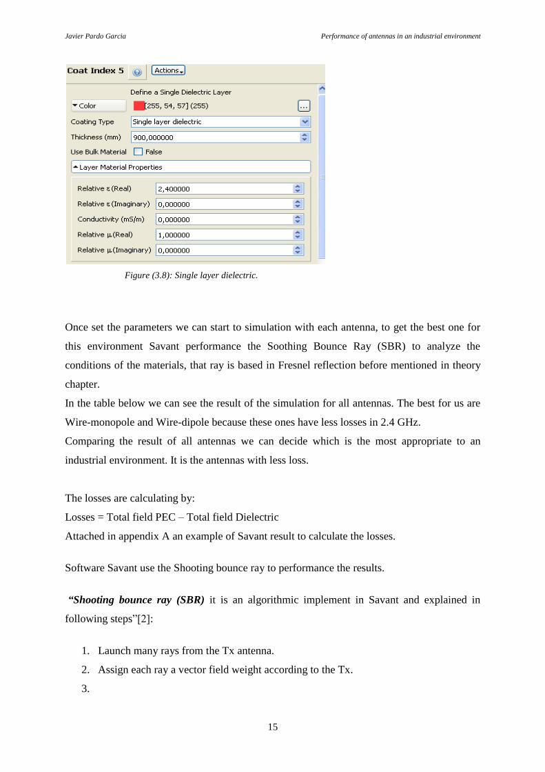
We have to set the characteristics of the antennas for Metal (PEC) Figure (3.7) and Single
layer dielectric Figure (3.8). For Single layer dielectric we will set the characteristic of the
thickness (900mm) and permeability (Teflon 2,4).
Figure (3.7): Setting the coating.
Figure (3.6): Setting the range of frequency that
we are going to work.
Javier Pardo Garcia Performance of antennas in an industrial environment
15
Figure (3.8): Single layer dielectric.
Once set the parameters we can start to simulation with each antenna, to get the best one for
this environment Savant performance the Soothing Bounce Ray (SBR) to analyze the
conditions of the materials, that ray is based in Fresnel reflection before mentioned in theory
chapter.
In the table below we can see the result of the simulation for all antennas. The best for us are
Wire-monopole and Wire-dipole because these ones have less losses in 2.4 GHz.
Comparing the result of all antennas we can decide which is the most appropriate to an
industrial environment. It is the antennas with less loss.
The losses are calculating by:
Losses = Total field PEC – Total field Dielectric
Attached in appendix A an example of Savant result to calculate the losses.
Software Savant use the Shooting bounce ray to performance the results.
“Shooting bounce ray (SBR) it is an algorithmic implement in Savant and explained in
following steps”[2]:
1. Launch many rays from the Tx antenna.
2. Assign each ray a vector field weight according to the Tx.
3.
Javier Pardo Garcia Performance of antennas in an industrial environment
16
a. The ray is ignored if it is escapes to space.
b. It is generate a reflected ray when the ray hits a surface. Compute its fields
according to the incident ray fields, the material properties of the surface.
c. Also generate a transmitted in the same direction as the incident ray and then
extend and process it as one would the reflected ray if the ray hits a penetrable
surface.
4. The incident and reflected field on the surface are compute by. Use these and the PO
approximation to determine equivalent surface currents.
5. Radiate the equivalent currents to observation angles/points.
a. If the obsrvation point represents an Rx antenna, compute the coupling of the
radiated fields into the receiver according to the Rx antenna pattern or current
distribution.
6. Continue tracing the reflected ray generated in step 3b and repeate from there.
Likewise for any transmitted ray generated in step 3c. Continue until either the ray
escapes (Step 3a) or the maximum bounce limit is reached.
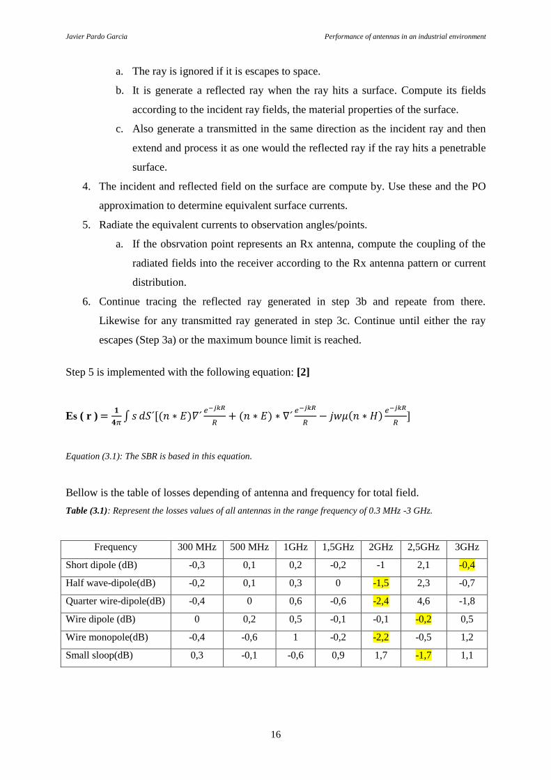
Step 5 is implemented with the following equation: [2]
Es ( r )
Equation (3.1): The SBR is based in this equation.
Bellow is the table of losses depending of antenna and frequency for total field.
Table (3.1): Represent the losses values of all antennas in the range frequency of 0.3 MHz -3 GHz.
Frequency 300 MHz 500 MHz 1GHz 1,5GHz 2GHz 2,5GHz 3GHz
Short dipole (dB) -0,3 0,1 0,2 -0,2 -1 2,1 -0,4
Half wave-dipole(dB) -0,2 0,1 0,3 0 -1,5 2,3 -0,7
Quarter wire-dipole(dB) -0,4 0 0,6 -0,6 -2,4 4,6 -1,8
Wire dipole (dB) 0 0,2 0,5 -0,1 -0,1 -0,2 0,5
Wire monopole(dB) -0,4 -0,6 1 -0,2 -2,2 -0,5 1,2
Small sloop(dB) 0,3 -0,1 -0,6 0,9 1,7 -1,7 1,1

Javier Pardo Garcia Performance of antennas in an industrial environment
17
Figure (3.2): Represent the losses of the antennas in the range o frequency of 0.3 MHz -3 GHz, X-axis frequency
and Y-axis (dB).
3.1 Wire-dipole and wire-monopole simulation: In the range of
frequency of 2.4 GHz and with different distance the results are.
The losses of both antennas are:
Losses = Total field Metal (PEC) – Total field of Single layer dielectric
Table (3.1.1): Represent the values of both antennas with different distance.
Frequency 2,4GHz 1 m 5 m 10 m 15 m 20 m 50 m
Wire dipole (dB) -105 -106 -115 -119 -124 -135
Wire monopole (dB) -108 -124,5 -129,1 -138,5 -143,5 -159,3
We can observe that when we are increasing the distance the power is decreasing, depending
of the polarization we have the same results table (3.1.2) and table (3.1.3) from here we are
getting a conclusion.
-3
-2
-1
0
1
2
3
4
5
300 Mhz 500 Mhz 1Ghz 1,5Ghz 2Ghz 2,5Ghz 3Ghz
Short dipole (dB)
Half wave-dipole(dB)
Quarter wire-dipole(dB)
Wire dipole (dB)
Wire monopole(dB)
Small sloop(dB)

Javier Pardo Garcia Performance of antennas in an industrial environment
18
Figure (1): Losses at 2.4 GHz, X-axis distance (m) and Y-axis (dB).
Depending of the polarization:
Vertical:
Table: (3.1.2): show the losses in the vertical polarization.
Frequency 2,4GHz 0,1 m 1 m 5 m 10 m 15 m 20 m 50 m
Wire dipole (dB) -100 -102 -104 -111 -116 -122 -137
Wire monopole (dB) -100 -103 -106 -113 -118 -124 -138
Horizontal:
Table: (3.1.3): show the losses in the horizontal polarization.
Frequency 2,4GHz 0,1 m 1 m 5 m 10 m 15 m 20 m 50 m
Wire dipole (dB) -101 -107 -109 -119,4 -125,5 -130 -145,8
Wire monopole (dB) -102 -106 -109 -121 -126,5 -130 -145,8
-180
-160
-140
-120
-100
-80
-60
-40
-20
0
0 10 20 30 40 50 60
Dipole
Monopole
Javier Pardo Garcia Performance of antennas in an industrial environment
19
4 Discussion and conclusion
In this thesis, we can see the different antennas and with different distances and polarizations,
according to the simulations we can discuss that for an industrial environment the best
antennas are dipole and monopole because these both antennas present low losses in this
hostile environment. [10]
Simulating environments with high reflective and amount of metal structures and medium
reflective environments and with some metals we calculate the losses and the antenna
properly.
In the frequency of 2.4 GHz both meet Power= 1/ (distance)2
so if when the antennas are
away then the power is low and when the antennas are close then the power is high. For
having a good service of the antennas in industrial environment we should take the
measurements depending on the materials and the losses and by taking the best distance to
satisfy our requirements.[8]
To take the best antenna and the environment we can even consider the polarization view.
In the Figure (3.2) we have seen the frequency of the antenna at less numbers of points and
this is due to the limitation of software to simulate only 300MHz to 3GHz with the spam of
0.5 GHz.
The frequency 2.4GHz was not included due to the limitation of the software and moreover
the performance of the antennas at 2.4 GHz will be similar as at 2.5GHz.
Javier Pardo Garcia Performance of antennas in an industrial environment
20
References
[1] Javier Ferrer Coll RF Channel Characterization in industrial, Hospital and home
Environments. KTH communication Systems. February 2012
[2] www.delcross.com 2012-05-09
[3] Constatine A. balains Antenna Theory Second edition . Analysis of design. 1997
[4] Jose Abel Hernandez Rueda Antennas Basic principles analysis and design. First
published 1961
[5] Y.Jay and Stephen K.Barton Fresnel zone antennas. August 31 2002.
[6] Belotserkovski, Marcombo Antennas Fundaments. 1938.
[7] S.Krishnamoorthy, J Reed C.Anderson, P. Max Robert, and S. Srikanteswara
“Characterization of the 2,4GHz ISN band electromagnetic interference in a hospital
environment ” Proceeding of the 25th
Annual international conference of IEEE, vol.4 Sep
2003.
[8] S. Stellingwerff Beintema and Radio-Holland B.V.,” The use of radiofrequencies for
electromagnetic positioning systems and the application in secel´s sydelis.” Febreary 1977
[9] E.Hanada, Y.Antoku, S.Tani, M.kimura, A. Hasegawa, S. Urano, K Ohe.
“Electomagnetic interference on medical equipment by low power mobile
telecommunications systems” Electromagnetic Compatibility IEEE Transactions on ,vol 42
no. 4, pp. 470-476, Nov 2000.
[10] J.liang amd Q. liang ”Outdoor propagation channel modeling in foliage environment”
Vehicular Techonology, IEEE transactions on vol 59, no 5. Jun 2010
Javier Pardo Garcia Performance of antennas in an industrial environment
A1
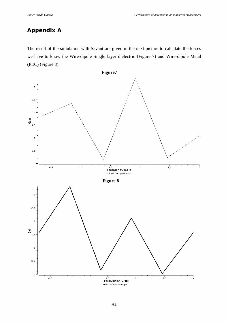
Appendix A
The result of the simulation with Savant are given in the next picture to calculate the losses
we have to know the Wire-dipole Single layer dielectric (Figure 7) and Wire-dipole Metal
(PEC) (Figure 8).
Figure7
Figure 8
Javier Pardo Garcia Performance of antennas in an industrial environment
B1
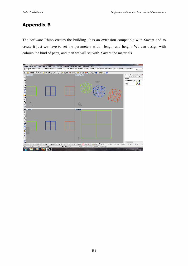
Appendix B
The software Rhino creates the building. It is an extension compatible with Savant and to
create it just we have to set the parameters width, length and height. We can design with
colours the kind of parts, and then we will set with Savant the materials.