facts controllers - shodhgangashodhganga.inflibnet.ac.in/bitstream/10603/93264/... · 2.3. basic...
TRANSCRIPT

CHAPTER- 2
FACTS CONTROLLERS

CHAPTER 2
FACTS CONTROLLERS
2.1 OVER VIEW OF FACTS:
The rapid development of power electronics technology provides exciting
opportunities to develop new power system equipment for better utilization of existing
systems. Since 1990, a number of devices under the term FACTS (flexible AC transmission
systems) technology have been proposed and implemented [I ] .
Flexible AC Transmission Systems (FACTS) are the name given to the application of
power electronics devices to control the power flows and other quantities in power systems.
IEEE Definitions FACTS are AC transmission systems incorporating the power
electronic-based and other static controllers to enhance controllability and increase power
transfer capability.
FACTS devices can be effectively used for power flow control, load sharing among
parallel corridors, voltage regulation, and enhancement of transient stability and mitigation
of system oscillations. By giving additional flexibility, FACTS controllers can enable a line
to carry power close to its thermal rating. Mechanical switching has to be supplemented by
rapid response power electronics. It may be noted that FACTS is enabling technology, and
not a one-on-one substitute for mechanical switches [2-3).
FACTS employs high speed thyristor for switching in or out transmission line
components such as capacitors, reactors or phase shifting transformers for desirable
performance of systems. The FACTS technology is not a single high power controller, but
rather a coilection of controllers, which can be applied individually or in coordination with
others to control one or more of system parameters. It started with the High Voltage DC
Current (HVDC) transmission, and Static Var Compensator (SVC) systems were employed
later for the reactive power compensation of power transmission lines. Subsequently,
devices like Thyristor Controlled Series Compensator (TCSC), Static Compensator
(STATCOM), Static Synchronous Series Compensator (SSSC) and Unified Power Flow

Controller (UPFC) are proposed and installed under the generic name of Flexible AC
Transmission Systems (FACTS) controllers 141.
2.2. RELATIVE CONTROLLABLE PARAMETERS OF FACTS 151
Control of the line impedance X (with a thyristor controlled series capacitor) can
provide a powerful means of current control.
When the angle is not large, control of X or the angle substantially provides the
control of active power.
Control of angle (with a phase angle regulator), which in turn controls the driving
voltage, provides a powerful means of controlling the current flow and hence
provides active power flow when the angle is not large.
111-jecting the voltage in series with the line, and perpendicular to the current flow,
can increase or decrease the magnitude of current flow. Since the current flow lags
the driving voltage by 90°, the injection of reactive power in series, can provide a
powerful means of controlling the line current.
Injecting voltage in series with the line and with any phase angle with respect to the
driving voltage can control the magnitude and the phase of the line current. This
means that injecting a voltage phasor with the variable phase angle can provide a
powerful means of precisely controlling the active and reactive power flow. This
requires injection of both active and reactive power in series.
Because the per unit line impedance is usually a small fraction of the line voltage,
the MVA rating of a series controller will often be a small fraction of the
throughout line MVA.
When the angle is not large, controlling the magnitude of one or more line voltages
can be a very cost-effective means for the control of reactive power flow through
the interconnection.
Combination of the line impedance control with a series controller and voltage
regulation with a shunt controller can also provide a cost-effective means to control
both the active and reactive power flow between the two systems.
2.3. BASIC TYPES OF FACTS CONTROLLERS
In general, FACTS controllers can be divided into four categories 16-81
Series Control.lers
Shunt Controllers
Combined series-series Controllers
Combined series-shunt Controllers
2.3.1 Series Controllers
The series controller could be variable impedance, such as a reactor, capacitor, etc.,
or power electro~iics based variable source of main frequency, sub synchronous and
harmonic frequencies to serve the desired need. In principle, all series controllers inject
voltage in series with the line. As long as the voltage is in phase quadrature with the line
current, the series controller only supplies or consumes variabte reactive power. Any other
relationship will involve handling of real power too.
2.3.2 Shunt Controllers
As in the case of series controllers, the shunt controllers may be variable
impedance, variabfe source, or a combination of these. In principle, all shunt controllers
inject current into the system at the point of connection. Even a variable shunt impedance
connected to the line voltage causes a variable current flow and hence represents injection
of the current into the line. As long as the injected current is in phase quadrature with the
line voltage, the shunt controller only supplies or consumes variable reactive power. Any
other phase relationship will involve handling of real power too.
2.3.3 Combined Series-Series Controllers
This could be a separate series controllers, which are controlled in a coordinated
manner, in a multifine transmission system, or it could be a unified controller. Series
controllers provide independent series reactive compensation for each line and also transfer
real power among the lines via the power link. The real power transfer capability of
the unified series-series controller, referred to as Inter Line Power Flow Controller, makes
it possible to balance both the real and reactive power flow in the lines and thereby
maximize the utilization of the transmission system,

2.3.4 Combined Series-Shunt Controllers
There could be a combination of separate shunt and series controllers, which are
controlled in a coordinated manner or a Unified Power Flow Controller with series and
shunt elements. In principle, combined shunt and series controllers inject current into the
system with the shunt part of the controller taking case of the current while voltage in
series in the line with the series part of the controller. However, when the shunt and series
controllers are unified there can be real power exchange between the series and shunt
controllers via the power link
2.4. BENEFITS OF UTILIZING FACTS DEVICES
The benefits of utilizing FACTS devices in electrical transmission systems can be
summarized as follows [9 ] :
2.4.1 Technical Benefits
Better utilization of existing transmission system assets
Increased transmission system reliability and availability
Increased dynamic and transient grid stability and reduction of loop flows
Increased quality of supply for sensitive industries
Control of power flow as ordered. The use of control of the power flow may be to
follow a contract, meet the utilities own needs, and ensure optimum power flow.
Increase the loading capability of lines to their thermal capabilities, including short
tern and seasonal.
Increase the system security by raising the transient stability limit, limiting short -
circuit currents and overloads.
Provide secure tie line connections to neighbouring utilities and regions thereby
decreasing overall generation reserve requirements on both sides.
Provide greater flexibility in siting new generation.
Upgrade of lines.
Reduce reactive power flows, thus allowing the lines to carry more active power.
Reduce koop flows.
Increase utilization of lowest cost generation.

2.4.2 Financial Benefits of FACTS Devices
There are three areas where the financial benefits can be calculated easily.
Additional sales due to increased transmission capability.
Additional wheeling charges due to increased transmission capability.
Avoiding or delaying of investments in high voltage transmission lines or even new
power generation. Maintenance of FACTS devices is minimal and similar to that
required for shunt capacitors, reactors and transformers. It can be performed by
normal substation personnel with no special procedures. The amount of
maintenance ranges from 150-250 man hours per year and depends upon the size of
the installation and the local ambient (pollution) conditions.
2.4.3 Environmental Benefits
FACTS devices are environmentally friendly. They contain no hazardous materials
and produce no waste or pollutants. FACTS help the distribution of the electrical energy
more economically through better utilization of existing installations, thereby reducing the
need for additional transmission lines.
2.5 NEW TRANSMISSION TECHNOLOGIES
Electrically restructuring envisions the transmission system as flexible, reliable, and
open to all exchange no matter where the suppliers and consumers of energy are located.
Today, however, the transmission system cannot fully support such diverse and open
exchange. Desirable market transactions today are quite different from those envisianed
when the transmission system was designed; executing them may stress the limits of safe
operation. The risks posed by such transactions may not be recognized in time to avert
major system was designed; executing them may stress the limits of safe operation, the
risks posed by such transactions may not be recognized in time to avert major system
emergencies. It is also increasingly common for one transmission to interfere with the safe
execution of others, producing "congestion" in the system. Militating congestion is
technically dificult and poses new administrative challenges when the paths are long
enough to span regions that have not to coordinate such operations in the past. In addition,

the technical infrastructure required to manage operations reliably may be overwhelmed by
the sheer volume of data and information concerning system conditions, transactions, and
events.
These problems can be remedies in part by physical reinforcements to the
transmission system, sometimes through new construction but increasingly through broader
use of improved hardware technologies. However, the greater strategic is needed for
indirect reinforcements to the general infrastructure for grid operations and planning. It is
at this level that transmission needs are recognized, options for countering those needs are
assessed and a balance is achieved between new transmission assets and new operating
methods. Timely development and deployment of requisite technology is a major element
throughout this process. But requisite technology is not exclusively a new one, There is
today a backlog of prototype technologies that can be adapted to power system
applications, given the incentive and the means to do so.
Progress in transmission system reinforcements has, for many years, been hampered
by yet another aspect of electricity restructuring. The boundaries of operation and planning
responsibilities are no longer clearly delineated. This process is far from complete, and it
has greatly weakened the essential dialog between technology developer and technology
users. Development of new technology must be clasely linked to its actual deployment for
operational use. Together, both activities should reflect, serve and keep pace with the
evolving in fraction needs of transmission organizations. The present level of uncertainty
precludes this once orderly process.
Neither the details nor the needs of the future in fracture for grid management are
well known, and all parties are understandably averse to investments that may not be
promptly and directly beneficial to them. Some utilities are concerned that transmission
investments may be greater benefit to their competitors than to themselves. In the near
term, relief of congestion may harm their business, As a result of such faces many
promising technologies are stranded at various points in the "pipeline" from concept to
practical use. Included among them are superconducting equipment, large scale devices for
routing power flow on the grid, real time operating tools for enhanced management of grid

assets, and a new generation of system planning methods that are against the many kinds of
uncertainty that are emerging in the new power system.
Another important issue is that some enabling technologies for healthy and reliable
energy commerce are not perceived as profitable enough to attract the interest of
commercial developers. Some means should be found for developi~~g and deploying such
technologies in furtherance of the public good [93.
2.5.1 Technology issues
Assuming that sufficient generated power is available, the challenge is to ensure the
reliable operational performance of the delivery system. Reliable system requires
coordinated management of both generation and transmission assets, since the pattern of
generation strongly influences "loadability" of the transmission lines. Restructuring has
greatly reduced the degree to which grid operators can manage the generation side of this
relationship, so the emphasis here is upon enhanced system performance through
improvements in transmission capabilities alone. Focus items include the following [lo]:
Q Passive reinforcements through new alternating current device
configurations and materials, to include superconducting technology,
f Indirect information reinforcements through improved models, methods
and toolsets for estimating the limits of safe operation and operating
within them,
*:* Direct information reinforcements through real-time monitoring and
performance assessment of critical devices and overall system behavior,
*:* Controllability reinforcements through flexible AC Transmission System
(FACTS) device, conventional high voltage direct current (HVDC), and
lower power level HVDC ("DC lite"),
*:* Operations based reinforcements that manually or automatically regulate
HVDC FACTS and other controllable devices in order to best manage
network power flows,
*:+ Robust design methods that combine the above reinforcements to achieve
high levels of system performance together with sufficient operational
reliability and
Performance certification methods which all major devices connected

to the transmission system are determined to operate according to the
information provided to system planning and operations staff, and according
to established engineering practice.
The electric utilities system for transmitting and distributing power is to be fine
tuned, to an unprecedented degree, by the application of power electronics,
microprocessors and thyristors in general. With these new technologies transmission and
distribution of electricity will be more reliable, more controllable and more efficient. The
flexible transmission system is akin to HVDC, related to thyristor developments and
designed to overcome the limitations of present mechanically controlled AC power
transmission systems.
By using reliable high speed power electronic controllers, the technology offers five
unique advantages over other systems:
k Greater control of power, so that it flows on the prescribed transmission
routs,
P Secure loading (but not over1oading)of transmission lines to levels nearer to
their thermal limits,
P Greater ability to transfer power between controlled areas so that the
generation reserve margin may be reduced to 15% from 18%,
P Prevention of cascading outages by limiting the effects of faults and
equipment failure and
k Damping of power system oscillations, which could be of faults and
equipments failures.
The flexible system owes tighter transmission control to its ability to manage the
interrelated parameters that constrain today's system, including series impedance, shunt
impedance, phase angle, and the occurrence of oscillations at various frequencies below the
rated frequency. By adding to flexibility in this way, the controllers enable transmission
line to function nearer to its thermal rating; it is not often possible means alone, as tap
changes, phase shifters, and switched capacitors and i~~ductors (reactors). The new
technology is not a single, high cost efficient power electronic controller that wipes out all
conventionat methods and their disadvantage, but rather a collection of controllers, which

can be applied individually or collectively in a specific power system to control the five
interrelated functions already mentioned the thyristor is the basic power electronic
controller which has become the magic word in flexible AC systems just like a transistor in
integrated circuitry.
Electric power networks integrate generation and load centers within each utility
system and through interconnections among neighboring systems, share power with vast
regional grids. ?'he purpose of this is to take advantage of the diversity of loads, changes in
peak demand due to time differences, the availability of different generation reserves in
various geographic regions, power sharing arrangements among utilities, shifts in fuel
prices, regulatory changes, and other discrepancies.
By facilitating bulk power transfers, these interconnected networks help minimize
the need to enlarge power plants and enable neighboring utilities and regions to buy and
seH power among themselves, Thus, the electric power transmission will result in less
reliable more costly power[l 01.
2.5.2 Regulating the Flow of Power
At present many transmission facilities confront one or more limiting network
parameters plus the inability to direct power ftow at wilt. We know that the power low
between two points is equal to the product of the voltages at the two points, times the sine
of the phase angte difference between the two points divided by the transmission line's
reactance.

Figure 2.1 : Power flow relation
Power transmissiorl Power a series compensated tie line is governed by the expression
U,U, sin (// P(t) =
x, - x,. By proper control of the TCSC, the overall transfer reactance i s modulated
X-time in such a way that the power oscillations are damped out.
In international power systems, the actual power flow from one region to another
might take unintended routes depending on impedances of transmission lines connecting
the areas. Controlled series compensation is a useful means for optimizing power flow
between regions for varying loading and network configurations. It becomes possible to
control power flows in order to achieve a number of goals [19]:
Minimizing of system losses
> Reduction of loop flows
P Elimination of line overloads
k Optimizing of load sharing between parallel circuits
l+ Directing of power flows along contractual paths

The following illustration explains the power in a normal AC transmission system and in
that of flexible system.
Figure 2.3 Figure 2.4
There are two generators (A&B) sending power to load centre through a network
consisting of three lines in a meshed connection. The lines AB, BC and AC have
continuous ratings of 1000 M W, respectively, with emergency rating of twice those figures.
For the impedances shown, the three lines would carry 600 MW, 1600 MW, and 1400 MW
respectively. Such a situation would overload one line. Power flows in accordance with
transmission line impedances that bear no relationship with transmission ownership,
contracts or thermal limits. If the owner of generator A had a contract with utilize C to
deliver power of 1500MW, he would supply 1 OOMW short of the contract as shown in the
power flow diagram effectively C but still receives the required power through the other
loop ABC virtually from A.
If however, a capacitor whose reactance is j5 ohms at the synchronous frequency is
inserted in one line (as shown in figure 4), it reduces the line's impedance from 10 ohms to
5 ohms, so that the power flow through the lines would be 250MW, 1250 MW, and 1750
MW respectively. By adjusting the value of capacitor properly one can exactly determine
the quantity of power flow through the line in accordance with contracts and ownership.
Similar results may be obtained by increasing the irnpendence of one of the lines in the
same meshed configuration by inserting a 7 ahm in series with the line (as shown in
Fig. 2.5).

In either case a thyristor controlled phase angle regulator could be installed instead
of a series or a series inductor in any of the three lines to serve the same purpose. The
inductor and the phase angle do not contribute to sub synchronous resonance. A phase
angle installed in line AC reduces the phase angle difference from 8.5 degrees to 4.2
degrees Fig.2.6 [20].
&,s n I750 MN
LOOII M W
LOAD
Figure 2.5 Figure 2.6
Generally a combination of mechanicalty controlled and thyristor controlled series
capacitor, series inductor or phase angle regulator is used to counter the system constraints
at minimum capital cost. Several thyristor based controllers are presently being used for
flexihle transmission systems. The first generation controllers had two thyristor based
systems that have found use in some systems.
Series capacitors have been successfully utilized for many years in electric power
networks. With series compensation, it is possible to increase the transfer capability of
power transmission systems at a favorable investment cost and with a short installation
time compared to the building of additional lines; this is due to the inherent ability of series
capacitors to achieve:
P Increased dynamic stability of power transmission systems
> Improved voitage regulation and reactive power balance
> Improved load sharing between parallel lines
The capacitor should be modular and mechanically switched, but the number of
operations would be severely limited by wear on the mechanical components. Other
complications may also arise. A series capacitor in a line may lead to sub synchronous

response at 15-30 Hz. This response occurs when the mechanical response frequency of the
shaft of the generator at risk c~incides with 50Hz (60Hz in America) minus the electrical
response frequency of the capacitor in series with the total system impedance. If such
response persists, it soon damages the shaft of the generator. This eventually causes the
power lines to operate at their emergency ratings and carry higher power loads producing
power flow oscillations which put the generators out of synchronism, perhaps prompting
the system's collapse [21].
Uprathg of series cwacitor into TCSC (wical d u e s )
Figure 2.7
With the advent of thyristor control, the concept of series compensation has been
broadened and its use has been increased further. Thyristor controlled series compensation
(TCSC) introduces a number important new benefit in the application of series capacitors:
k Mitigation of sub synchronous resonance risks
> Damping of active power oscillations
k Post-contingency stability improvement
k Dynamic Power Flow Control
Applicable in new as well as existing, the benefits of thyristor controlled series
compensation are by no means attainable only for installations starting from scratch. It is
fully possible and practicable also to upgrade existing series capacitors by making all of
them thyristor controlled, thereby extending their impact and usefulness in the grid most
considerably. This has been practiced in reality already 14-51.
2.5.3 Mitigation of SSR
The phenomenon of Sub Synchronous Resonance (SSR) has caused concern in the
past in situations where the risk for occurrence of SSR has acted as an impediment to the
use of series compensation in cases where the technology would otherwise have offered the

best and most economical solution. With the advent of TCSC, no such concerns need be
entertained any longer, and series compensation can be used to its fullest merit [ I 1.
The SSR risk used to be linked to the utilization of series compensation of
transmission lines fed by thermal generation, particularly in case of high degrees of
compensation, where analysis showed that the complementary series resonance frequency
of the compensated line(s) coincided with some damped tensional vibration frequency of
the turbo-generator shaft, and could hence induce increased mechanical stresses in the
shafis[2].
The TCSC acts to eliminate this risk for coinciding resonance frequencies by
making the series capacitor(s) act inductive in the sub synchronous frequency hand, thereby
rendering the occurrence of series resonance in the transmission system for sub
synchronous frequencies altogether impossible. This inductive character of the TCSC is
made possible by the use of a thyristor controlled inductor in parallel with the series
capacitor. The system is governed by an patented control scheme called SVR (Synchronous
Voltage Reversal)[S-63.
2.5.4 Damping of Power Oscillations
Oscillations of active power in power transmission systems may arise in corridors
between generating areas as a result of poor damping of the interconnections, particularly
during heavy power transmission. Such oscillations can be excited by a number of reasons
such as line faults or a sudden change of generator output. The presence of active power
oscillations acts to limit the power transmission capacity of interconnections between areas
or regions or even countries. It is often possible to find remedy by building additional lines
or upgrading existing lines, but this cost a lot of money and takes a lot of time, if not
rendered impossible altogether by lack of the necessary permits. In some cases, it may also
be possible to introduce power system stabilizers(PSS) on generators, but this will not
always work, particularly not for inter-area power osciHations which tend to be of a low
frequency (typically 0, 2 Hz to 0, 7 Hz). In either case, TCSC will be an attractive
alternative to consider. It offers a cost-effective, robust power oscillation damper,

insensitive to its location in the system and nano interacting with local oscillation models.
In a number of cases, it will turn out to be the best practicable solution [32J.
Figure: 2.8 Power oscillations damped out by means of TCSC
2.6 OPERATION OF FACTS DEVICES
Normally FACTS devices are operated automatically. They can be located in
unmanned substations. Changing af set-points or operation modes can be done locally and
remotely (example from the substation control room, from a regional control center, or
from a national control center) [ 1-21.
2.6.1 Steps for the identification of facts projects
The first step should always be to conduct a detailed network study to
investigate the critical conditions of grid or grids connections. These conditions
can include risks of voltage problems or even voltage collapse, undesired power
flows, as well as the potential for power swings or sub synchronous resonances.
For a stable grid, the optimized utilization of the transmission lines, example
increasing the energy transfer capability can be investigated.
8 If there is a potential for improving the transmission system, either through
enhanced stability or energy transfer capability, the appropriate FACTS device
and its required rating can be determined.

Based on this technical information, an economical study can be performed to
compare costs of FACTS devices are conventional solutions with the achievable
benefits.
2.6.2 Performance verification
The design of all FACTS devices should be tested in a Transient Network Analyzer
(TNA) under all possibte operational conditions and fault scenarios. The results of the TNA
tests should be consistent with the results of the network study, which was performed at the
start of the project. The results of the TNA study also provide the criteria for the evaluation
of the site commissioning tests.
2.7. POWER ELECTRONIC APPLICATIONS IN POWER TRANSMISSION
SYSTEM
Facts Controllers A power electronic based system & other static equipment that
provide control of one or more AC transmission parameters.
The development of FACTS controllers has followed two different approaches. The
first approach employs reactive impedances or a tap changing transformer with thyristor
switches as the controlled elements, the second approach employs self cornmutated static
converters as voltage sources. In general these are categories [ I -21
In series with the power system (series compensation)
In shunt with the power system (shunt compensation)
Both in series and in shunt with the power system
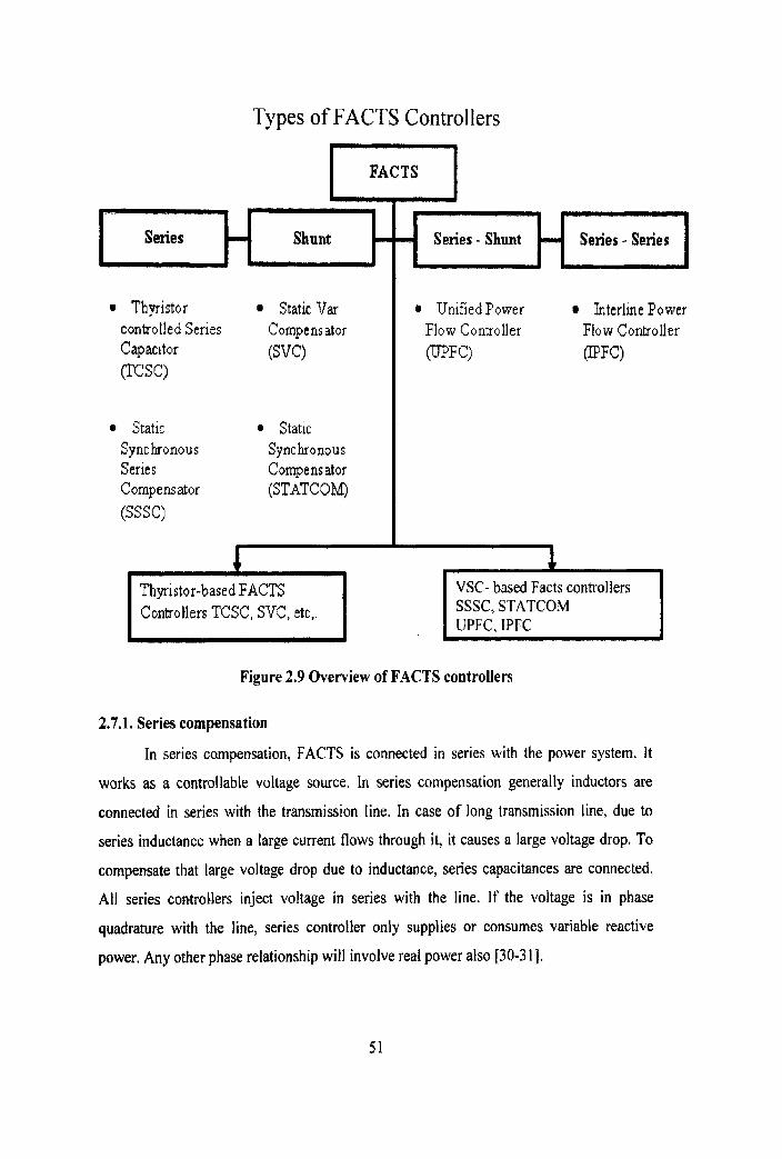
Types of FACTS Controllers
I FACTS I
Thyristor I Static Var controlled Series Compensator Capacitor (SVC)
Crcsc>
Static 0 Static Synchronous Synchronous Series Compensator Compensator (STATC Ohll) (SSSC)
4
Series - Shunt Series - Series
Unified Power Interline Power Flow Controller Flow Controller EUPFC) (IPFC)
I Thyristor-based FACTS Controllers TCSC, SVC, etc,. I SSSC, STATCOM
UPFC. IPFC
Figure 2.9 Overview of FACTS controllers
2.7.1. Series compensation
In series compensation, FACTS is connected in series with the power system. It
works as a controllable voltage source. In series compensation generally inductors are
connected in series with the transmission line. In case of long transmission line, due to
series inductance when a large current flows through it, it causes a large voltage drop. To
compensate that large voltage drop due to inductance, series capacitances are connected.
All series controllers inject voltage in series with the line. If the voltage is in phase
quadrature with the line, series controlier only supplies or consumes variable reactive
power. Any other phase relationship will involve real power also [30-3 I}.

Tasks of dynamic series compensation:
Reduction of load dependent voltage drops
Reduction of system transfer impedance
Reduction of transmission angle
Increase of system stability
Load flow control for specified power paths
Damping of active power oscillations
2.7.1.1 Static Synchronous Series Compensator (SSSC)
The series reactive compensation scheme, using a switching power converter
(voltage source converter) as a synchronous voltage source to produce a controllable
voltage in quadrature with the line current can be defined as Static Synchronous Series
Compensator (SSSC). It can be defined by the equation j 101
Where, V, (0 is the magnitude of the injected compensating voltage (0 I V, (6) r: V,,,,) and <i is the control parameter. The SSSC consists of a series insertion transformer,
voltage sourced converter. The SSSC model is shown in the Fig. 2.10. SSSC is one of the
most important FACTS controllers [lo}.
Figure 2.10 Basic two machine system with synchronous voltage source.
It is like STATCOM, except that the output is in series with the line. It can be based
on a voltage sourced converter or a current sourced converter. Usually the injected voltage
in series would be quite small compared to the line voltage, and the insulation to the
ground would be quite high. With an appropriate insulation between the primary and

secondary of the transformer, the converter equipment is located on a platfor~n duly
insulated from the ground [47-481.
Prcef /%ef ) Qrerf (Xref )
Energy - Source
(Optional)
Figure 2.11 Functional representation of the synchronous voltage source based on a
voltage sourced converter.
The transformer ratio is tailored to the most economical converter design. Without
an energy source, SSSC can only inject a variable voltage which is 90' leading or lagging
the line current. The primary of the transformer and hence the secondary as well as the
converter have to carry full line current including the fault current unless the converter is
temporarily bypassed during severe line fault. An energy storage device can be connected
to the series controller to inject voltage with variable phase angle in series with the line.
2.7.1.2 Thyristor-Controlled Series Capacitor (TCSC)
The two basic schemes of thyristor-controlled series capacitors, using thyristor-
switched capacitors and a fixed capacitor in parallel with a thyristor-controlled Reactor, are
shown schematically in Fig. 2.12 and 2.13. In the thyristor-switched capacitor scheme of
Fig. 2.12 increasing or decreasing the number of capacitor banks in series controls the
degree of series compensation. To accomplish this, each capacitor bank is inserted or
bypassed by a thyristor valve (switch). To minimize switching transients and to utilize
"natural" commutation, the operation of the thyristor valves is coordinated with voltage and
current zero crossings. In the fixed-capacitor, thyristor-controlled reactor scheme of

Fig. 2.13, the degree of series compensation in the capacitive operating region (the
admittance of the TCR is kept below that of the parallel connected capacitor) is increased
(or decreased) by increasing (or decreasing) the thyristor conduction period, and thereby,
increasing the current in the TCR. Minimum series compensation is reached when the TCR
is off. The TCR may be designed to have the capability to limit the voltage across the
capacitor during faults and other system contingencies of similar effect. Connecting a
number of TCRs plus a fixed capacitor in series in order to achieve greater control range
and flexibility may combine the two schemes [ I -21.
Figure 2.12 TCSC with thyristor switched capacitance
Figure 2.13 TCSC with fixed capacitor
2.7.2 Shunt controller
This may be variable impedance, variable source or combination of these. All shunt
controllers inject current into the system at the point of connection. Combined series-series
cantrollers can be combination of separate series controllers which are controlled in a
coordinated manner. Combined series and shunt controllers are either controlled in
coordinated manner or a unified power flow controller with series and shunt elements for a

unified controller. There can be a real power exchange between the series and shunt
controllers via dc power link [I 3. Tasks of dynamic shunt compensation:
Steady state and dynamic voltage control
Reactive power control of dynamic loads
Damping of active power oscillations
Improvement of system stability
2 .7 .2 .1 Stat ic V A R Compensator (SVC)
Shunt-connected static VAR compensators (SVCs) are used extensively to control
the AC voltage in transmission networks. Power electronic equipment, such as the thyristar
controlled reactor (TCR) and the thyristor switched capacitor (TSC) have gained a
significant market, primarily because of well-proven robustness to supply dynamic reactive
power with fast response time and with low maintenance. With the advent of high power
gate turn-off thyristors and transistor devices ( 0 , IGBT, ...) a new generation of power
electronic equipment, STATCOM, shows great promise for application in power systems
installation of a large number of SVCs and experience gained from recent STATCOM
projects throughout the world motivate us to clarify certain aspects of these devices.
Fig. 2.14 shows a schematic diagram of a Static Var Compensator. The
compensator normally includes a thyristor-controlled reactor (TCR), thyristor-switched
capacitors (TSCs) and harmonic filters.
H W bus
LkLU n1n
Fi I ters
TSC
F i g u r e 2.14 S t a t i c var compensator

It might also include mechanically switched shunt capacitors (MSCs), and then the
term Static Var System is used. The harmonic filters (for the TCR-produced harmonics) are
capacitive at fundamental frequency. The TCR is typically larger than the TSC blocks, so
that continuous control is realized. Other possibilities are fixed capacitors (FCs), and
thyristor switched reactors (TSRs). Usually a dedicated transformer is used, with the
compensator equipment at medium voltage. The transmission side voltage is controlled,
and the Mvar ratings are referred to the transmission side [9- 101.
Typical configurations in SVC
The SVC typically consists of a TCR (Thyristor Controlled Reactor), a TSC
(Thyristor Switched Capacitor) and fixed capacitors (FC) in a harmonic filter arrangement
as shown in Fig. 2.14. The TCR consists of reactors and thyristor valves. The TCR
continuously controls reactive power by varying the current amplitude flowing through the
reactors. The TSC consists of capacitors, reactors and thyristor valves. The TSC switches
on and off the capacitors. The AC fiiters provide fixed reactive power and absorb the
harmonic current generated by the TCR. The TCRtFC is the most basic configuration of
the SVC. The TCRtTSCtFC, the more advanced configuration, can be tuned to minimize
the losses at the most frequent operation point. [2], [4].
A Inductive I
Cspdtb. ~ ~ ' R r Cmaciiim SVC Rmctkr)mvrr . SVC Rcutivcpcwr
TCR PC TCR TSC FC
Figure 2.15 Typical configuration of SVC

Applications of the SVC systems in transmission systems:
To increase active power transfer capacity and transient stability margin
To damp power oscitlations
To achieve effective voltage control
In addition, SVCs are also used
1. ln transmission systems
To reduce temporary over voltages
To damp sub synchronous resonances
To damp power oscillations in interconnected power systems
2. In traction systems
To balance loads
To improve power factor
'To improve voltage regulation
3. In HVDC systems
To provide reactive power to ac-dc converters
4. In arc furnaces
To reduce voltage variations and associated light flicker
i) TCR (Thyristor Controlled Reactor)
The amplitude of the TCR current can be changed cantinuously by varying the
thyristor firing angle. The firing angle can be varied from 9 0 9 0 180'. The TCR firing
angle can be fully changed within one cycle of the fundamental frequency, thus providing
smooth and fast control of reactive power supply to the system[l-21.

Figure 2 .16 T C R current and f i r ing angle
ii) TSC (Thyristor Switched Capacitor)
The TSC is used to switch on and off the capacitor bank. The TSC does not
generate any harmonic current components. The capacitor switching operation is completed
within one cycle of the fundamental frequency. The TSC provides a faster and more
reliable solution to capacitor switching than conventional mechanical switching devices.
The TSC can operate in coordination with the TCR so that the sum of the reactive power
from the TSC and the TCR becomes linear. Applications with only TSCs are also available,
providing stepwise control of capacitive reactive power.
V r ~ O t W - ~ c d I wn.w
0)
Figure 2 .17 TCS current and f i r ing angle

2.7.3 Static Compensator (STATCOM)
STATCOM systems essentially consist of a DC voltage source behind self
commutated inverters using insulated gate bipolar transistor (IGBT). gate turn-off (GTO),
or gate commutated turn-off (GCT) thyristors and an interconnecting transformer. The
voltage source inverter set connects to the power system, via a multi-winding or two
winding inverter transformer, depending upon the application. The Fig. 2.17 shows the
basic STATCOM configuration. The inverter and DC voltage source can be modeled as a
variable voltage source, as shown in the equivalent circuit (Fig, 2.18). The power system
also can be modeled as a voltage source. An inductor representing the leakage reactance of
the transformer connects the two voltage sources. The output voltage phase of'the thyristor-
based inverter, Vi, is controlled in the same way as the system vohage. Vs [ 1-21.
The compact design of STATCOM systems takes up approximately 113 the area
and 115 the volume of conventional Static Var Compensation (SVC) systems.
Figure 2.18 Static Compensator (STATCOM) and voltage /current characteristic
2.8 UNIFIED POWER FLOW CONTROLLER (UPFC)
Gyugui proposed unified power flow controller (UPFC) concept in 1991 [I] . The
UPFC was devised for real time control and dynamic compensation of AC transmission
system, providing multifunctional flexibility required to solve many problems facing the
delivery industry 111. Within the framework of traditional power concept, the UPFC is able
to control, simultaneously or selectively, all the parameters affecting power flow in

transmission line ( i t . , voltage, impedance , and phase angle ) and this unique capability is
signified by the ad.jective "unified, to its name. Alternatively, it can independently control
both the real and reactive power flow in the line. The col~trol of real power is associated
with similar changes in reactive power i,e., increased real power flow also results in
increased reactive line power 141.
2.8.1 Basic Circuit Arrangement
In the currently used practical implementation, the LJPI:C consists of two switching
converters, which in the implementations are considered as voltage source inverters using
gate turn-off (GTO) thyristor valves, as illustrated in Fig. 2.19. These back to back
converters, labeled "converter 1" and "converter 2" in thc ligure. are operated from a
common DC link provided by a DC storage capacitor. This arrangement functions as an
ideal AC-to-AC power converter in which the real power can freely flow in either direction
between the AC terminal of the two converters, and each converter can independently
generate or absorb reactive power at its own AC output termitlals 1221.
Figure 2.19 Basic circuit arrangement of Ilnified Power Flow Controller

2.8.2 Basic Operating Principle
Converter 2 provides the main function of the UPFC by injecting an AC voltage Vw
with controllable magnitude Vw (05Vps <Vwmd~) and phase angle 1360°, at the power
frequency, in series with the line via an insertion transformer. The injected voltage is
considered essentially as a synchronous voltage source. The transmission line current flows
through this voltage source resulting in real and reactive power exchange between insertion
transformer and the AC system. The real power exchange at the AC terminal (i.e., at the
terminal of insertion transformer) is converted by the inverter into DC power that appears at
the DC link as positive or negative real power demanded. The reactive power exchanged at
the AC terminal is generated internally by the inverter 120-221.
The basic function of converter 1 is to supply or absorb the real power absorbed by
the converter 2 at the common DC link to support the real power exchange resulting from
the series voltage injection. This DC link power demand of converter 2 is converted back
to AC by converter 1 and coupled to the transmission line bus via shunt connected
transformer. In addition to the real power need of converter 2, converter 1 can also generate
or absorb controllable reactive power, if desired, and thereby provide independent shunt
reactive compensation for the line. It is important to note that there is a closed direct path
for the real power negotiated by the action of series voltage injection through converters 1
and 2 back to the line. The corresponding reactive power exchanged is supplied or absorbed
locally by converter 2 and therefore does not have to be transmitted by the line. Thus,
converter I can be operated at a unity power factor or can be controlled to have a reactive
power exchanged by converter 2. Obviously, there can be no reactive power flow through
the UPFC DC link [20].
2.8.3 Transmission Control Capabilities
By viewing the operation of the unified power flow controller, the traditional power
transmission is based on reactive shunt compensation and phase angle regulation. The
UPFC can fulfill all these functions and thereby meet multiple control objectives by adding
the injected voltage Vw with appropriate amplitude and phase angle to the (sending end)

terminal voltage Vs. Using phasor representation, the basic LJPFC power flow control
functions are illustrated in Fig. 2.20[17].
2.8.3.1 Terminal Voltage Regulation
Voltage regulation is done by continuousiy variable in-phase /anti phase injection
for voltage increments Vpq =fV (~4). This is functionally similar to that which is
obtainable with a transformer tap changer having infinitely small steps.
2.8.3.2 Series Capacitor Compensation
Series reactive compensation is shown in Fig. 2.20(b) where Vpl =Vq is i~~jected in
quadrature with the line current. Functionally this is similar to series capacitive and
inductive line compensation attained by the SSSC; the injected series compensating voltage
can be kept constant, if desired, independent of line current variation, or can be varied in
proportion with the line current to imitate the compensation obtained with a series capacitor
or reactor [21].
2.8.3.3 Transmission Angle Regulation
Phase angle regulation is shown in Fig. 2.20(c) where Vpq =VO is in.jected with an
angular relationship with respect to V, that achieves the desired sigma phase shifted
(advance or retard) without any change in magnitude. Thus the UPFC can function as a
perfect phase angle regulator which can also supply the reactive power involved with the
transmission angle control by internal var generation.
2.8.3.4 Multifunctional Power Flow Control
Multifunctional power flow control, executed by simultaneously terminal voltage
regulation, series capacitive line compensation, and phase shifting, is shown in Fig. 2.1 1 (d)
where Vw=V+Vq+V,, This functional capability is unique to the UPFC. No single
conventional equipment has similar multifUnctional capability [16].

(a)
V '.-._ _ _ - v+ V"
(a) Voltage regulation (b) Line impedance cwnpensatton (c) Phase shiing (d) Simultaneous control of voltage, irnpedanoe, and an*
Figure 2.20 Phasor diagrams illustrating the transmission control capabilities of the
Unified Power Flow Controller
2.8.3.5 BASIC PRINCIPLES OF P AND Q CONTROL
Consider Fig. 2.10(a) at (a) a simple two machine (or two bus AC inter tie) system
with sending end voltage Vs, receiving end voltage Vr and the line or tie impedance X
(assumed for simplicity, inducted) is shown. At (b), the voltage of the system in the form of
a phasor diagram is shown with transmission angle 6 and /Vs I=IVrl=V. At (c) the
transmitted P(P=v~/xs~~G) and the reactive power Q=Q,=Q,(Q=V~/X(I-C~S~)) supplied at
the end of the line are shown plotted against angle 6. At (d) the reactive power Q=Q, =Q,
is shown plotted against the transmitted power P corresponding to "stable values of 6 (ie..,
03190)
Figure 2.21 (a)simple two machine system, (b) related voltage phasors, (c)real and
reactive power vs. transmission angle, and (d) sending end and receiving end reactive
power vs. transmission angle.

The basic power of Fig.2.21 with the well known transmission characteristics is
introduced for providing a vehicle to establish the capability of the UPFC. It controls the
transmitted real power P, and the reactive power demands Q, and Q, at the sending end and
the receiving end of the line respectively [34].
Consider Fig. 2.10 the simple power system is expanded to include the UPFC. The
UPFC is represented by a controllable voltage source in series with the line which, as
explained in the previous section, can generate or absorb reactive power that i t negotiates
with the line but the real power it exchanges must be supplied to it, or absorbed from it, by
the sending end generator. The UPFC in series with the line is represented by the phase V,
having magnitude V,, (0<V,5VP,,,,) and the angle p (O<p 5360) measured from the given
phase position of phasor V,, as illustrated in the figure. 'l'lie line current represented by
phasor 1 , flows through the series voltage source, V,, and generally results in both the
reactive and real power exchanges.
In order to represent the UPFC properly, the series voltage source is stipulated to
generate only the reactive power QPq which exchanges with the line. Thus the real power P,,
negotiates with the line assumed to be transferred to the sending end generators if a perfect
coupling for real power flow between it and the sending end generator existed. This is an
arrangement with the UPFC circuit structure in which the DC link between the two
constituent inverters establishes a bi-directional coupling for real power flow between the
injected series voltage source and the sending end bus [24].
As Fig. 2.10 implies, in the present discussion it is further assumed to clarify that
the shunt reactive compensation capability of the UPFC was not utilized. This is the UPFC
shunt inverter assumed to be operated at unity power factor, its sole function being to
transfer the real; power demand of the series inverter to the sending end generator. With
these assumptions the series voltage source together with the real power coupling to the
sending end generator as shown in Fig. 2.10 is an accurate representation of the basic UPFC

It can be readily observed in Fig. 2.10 which shows that the transmission line "sees"
Vs+ V, as the effective sending end voltage. Thus it is clear that the LJPFC effects the
voltage (both its magnitude and angle) across the transmission line and therefore it is
reasonable to expect that it is able to control by varying the magnitude and angle of V,, the
transmittable real power as well as the reactive power demand of the line at any given
transmission angle between the sending end and receiving end voltages [26].
2.9 INTERLINE POWER FLOW CONTROLLER (IPFC):
2.9.1 Basic Principles
The basic family of FACTS controller like SVC, SSSC, STATCOM, UPFC are
devised primarily for the control of single line. But thc objective of Interline Power Flow
Controller (IPFC) is to provide a comprehensive power flow control scheme for a multiline
transmission system, in which two or more lines employ an SSSC for series compensation.
A multiline IPFC comprises a number of n SSSC, one for each line of the transmission
system to be controlled, with a common DC bus, as illustrated schematically by a block
diagram 2.22. The IPFC scheme has the capability to transfer real power between the
compensated lines in addition to executing the independent and controllable reactive
compensation of each line. This capability makes it possible to equalize both real and
reactive power flow between the lines, to transfer power demand from overloaded to under
loaded lines, to compensate against resistive line voltage drops and the corresponding
reactive line power. It also increases the effectiveness of the compensating system for
dynamic disturbances like transient stability and power oscillation damping. The general
schematic diagram of the interline power flow controller is shown in Fig. 2.22. From the
Figure it is evident that by appropriately controlling the real power compensation the
reactive line power flow can be made constant and independent of the real power
transmitted [ 1 11.

Figure 2.22 General schematic of IYFC
2.9.2 Operation
The operation of the IPFC can be described with the two dimensional Q-P plot for
multiline transmission system. For example consider the jkh line of n-line system. This is
similar to that of a UPFC in which the achievable Q and P values lie within a circle drawn
around the Qo and Po points of the uncompensated line obtained at the prevailing phase
angle. The radius of the circle is proportional to the maximum magnitude of the injected
series compensating voltage. The compensation of the J ' ~ line within the IPFC scheme can
be characterized by the parallel shifting of the reactive compensation control line obtained
with purely reactive compensation when no real power supplied to or absorbed from the
line via the jth converter. If the jih converter supplies real power to the jth line, then the
reactive compensation line is shifted in the positive direction i.e., upwards and the reactive
power demand of this line decreases and also changes sign. lf the jth converter absorbs real
power from the jth line, then the compensation control line is shifted in the negative
direction i-e., downwards and the reactive power demand of this line increases. The Q-P
diagram illustrating the operation of IPFC is shown in Fig. 2.24. 'From the figure it is
evident that by appropriately controlling the real power compensation the reactive line
power flow can be made constant and independent of the real power transmitted [ I 2-1 31.

Figure 2.23 IPFC prime converter and corresponding phasor diagram.
P-Q control lines
cornpensatlon control line (qZ = 0)
Figure 2.24 Q-Pdiagramillustrating the operation of IPFC variation of receiving end
real and reactive power as a function of the injected compensating voltage in line I
The operation of a multi line IPFC requires the sum of the real power exchanged by
the total number of converter must be zero. In this the general idea of IPFC is that the
strong or under loaded lines are forced to help the weaker or overloaded lines in order to
optimize the utilization of the whole transmission system. This can be achieved by
connecting a shunt converter to compensate when the real power required by weaker line
exceeds the real power that can be absorbed. [14].
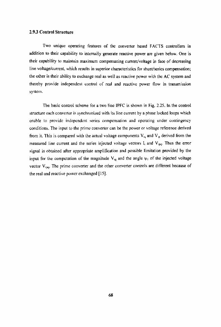
2.9.3 Control Structure
Two unique operating features of the converter based FACTS controllers in
addition to their capability to internally generate reactive power are given below. One is
their capability to maintain maximum compensating current/voltage in face of decreasing
line voltage/current, which results in superior characteristics for shundseries compensation;
the other is their ability to exchange real as well as reactive power with the AC system and
thereby provide independent control of real and reactive power flow in transmission
system.
The basic control scheme for a two line IPFC is shown in Fig. 2.25. In the control
structure each converter is synchronized with its line current by a phase locked loops which
enable to provide independent series compensation and operating under contingency
conditions. The input to the prime converter can be the power or voltage reference derived
from it. This is compared with the actual voltage components V,, and V,, derived from the
measured line current and the series injected voltage vectors 1, and V,,,. Thus the error
signal is obtained after appropriate amplification and possible limitation provided by the
input for the computation of the magnitude V,, and the angle yl of the injected voltage
vector V,,. The prime converter and the other converter controls are different because of
the real and reactive power exchanged [15].

mKlctlv. 1-w. v;
computer -
m-I comp. Vqp computer
K 6 c . Error
amplHkr &m.!l-
Error amplHler
Phase- locked Serles crmvartar 2 l W D A
Ma~nbtudrl Sonar and camrodar 2 - - anole VaP uale patmrn
computer 10gk
Figure 2.25 Basic control scheme for a two converter IPFC
2.9.4 Computer Simulation
The operation of the IPFC has been simulated with the use of the Electromagnetic
Transients Program (EMTP) simulation package. Referring to Fig. 2.25. An elementary
IPFC, composed of Voltage-Sourced Converters 1 and 2 with a common dc link, provides
(real and reactive) series compensation for lines1 and 2.The two-bus lines are assumed
identical; each has a sending-end voltage of 1.0 p.u., a receiving-end voltage of 1.O.p.u.
with a 30' transmission angle, and a line reactance of 5.0 p.u [I].
The converter in line 1 is operated as the "prime" converter which can inject a
voltage in series with line at any angle with respect to the sending-end voltage. Converter
2, on the other hand, is operated as a "support" converter compelled to inject a voltage in
series with line 2 so as to satisfy the real power demand (both supplied and absorbed) of the
converter 1 [ 1 1.

Fig 2.26 Waveforms showing the operation of the IYFC with the "prime" Converter 1
emulating real (resistive), capacitive, and inductive compensations of line 1
Figure 2.27 Waveforms showing the operation of Converter 2providing real power
demand of Converter 1 and capacitive series compensation for Line 2

Consider the case, shown in Fig. 2,28(a), where a voltage phasor VI, with a
magnitude of 0.1 3 p.u. is injected at -30'. In the corresponding simulation, Fig. 2.26 in the
0 to 50 rns interval shows the uncompensated line current i l , and the corresponding real
power P~~andreactive power Qr, at the receiving end of linel. Fig. 2.27 shows the
(identical) uncompensated line current i2, and the corresponding real power P2 and reactive
power Q2 at
1
(b)
6.1
V1p"
1
41
I
3
9J
.l
Figure 2.28 Illustration of the operation of a two-converter IPFC by coordinated phasor diagrams and P-Q plots.
the receiving end bus of line 2. At 50 ms, the voltage phasor V,,, stipulated in Fig. 2.28(a),
is injected to provide only real power compensation. As a result, Converter) supplies Plw
for linel. Converter2 is operated so as to absorb real power Pz, from line2. The sum of
PI,, and P2W for an ideal system must be zero. According to the ideal case illustrated in Fig.
2.28(a), the real and reactive power, PI, and QIr, should change from 11.0, -0.2681 p.u.
According to the illustrations to Fig. 2.28(d), P2, and Q2, should change from [ I .O, -0.2681
p.u. to [0.866, -0.51 p.u. The slight discrepancies in the simulation results are due to the
finite resistance of the transmission line reactance and the leakage reactance of'the coupling
transformer of the converter.
At 150 ms, a voltage phasor VIP, with a magnitude of 0.26 p.u. is injected at +45
degrees, as shown in Fig. 2.28(b), to emulate a capacitive reactance in series with the
transmission line. The line current i l , is at its ~naximum value. The values of PI, and Q I ,
should, with an ideal lossless system, change to [I .5, -0.1341 p.u.
At 250 ms, a voltage phasor VI, with a magnitude of 0.26 p.u. is injected at -75
degrees, as shown in Fig. 2.28(c), to emulate an inductive reactance in series with the
transmission line. The line current il, is at its minimum value. The values of P,, and QI,
should change to 10.634, 0.0981 p.u. In all these cases, the injected voltage phasor, Vlw
moves along the constant Plpq line. Therefore, both Plpq and P2,, should maintain the same
fixed values throughout this time. Also note that Converter2 in these three illustrations i's,
by choice, operated with zero reactive compensation, exchanging no reactive power with
line2 (Q2*=0), and thus the values of P2r and Qzr should stay at [0.866, -0.51 p.u.
At 350 ms, the operation of Converter2 is changed to inject a voltage phasor Vz,
with a magnitude of 0.26 p.u. so as to emulate a capacitive reactance, in addition to the
resistance (i.e., the real power demand of Converterl), in series with the transmission Line.
The real and reactive power, Pzr and Qzr should, in an ideal case, change to [1.366, -0.6341
p.u., without affecting PI, and Qlr.

Time (ms) : ---4 .--4
1 a, 4$0
Fig. 2.29 Real and reactive power in lines 1 and 2 when the IPFC is controlling the real power
in line 1 at unity power factor and maintaining constant real power flow in line2
The real and reactive power plots in Fig. 2.29 show the case in which the lPFC is
controlling the real power flow in (prime) linel, in response to a given reference, while
keeping the corresponding receiving-end reactive power practically at zero and maintaining
a substantially constant real power transmission in line2.This is achieved by appropriately
adjusting the real and reactive compensating voltage components in line2 to meet the real
power demand of line1 and maintain constant real power flow in line2[2].
2.9.5 Practical and Application Considerations
The concept and basic operating principles of the lPFC are explained for clarity
within the framework of two identical (and simple) systems in the previous section. In
practical applications the IPFC would, in general, have to manage the power flow control
of a complex, multiline system in which the length, voltage, and capacity of the individual
lines could widely differ. One of the attractive features of the IPFC is that it is inherently
flexible to accommodate complex systems and diverse operating requirements. A few
considerations relevant to practical applications are listed.
(1) The IPFC is particularly advantageous when controlled series compensation or
other series power flow control (e.g., phase shifting) is contemplated. This is because the

IPFC simply combines the otherwise independent series ctlrnpensators (SSSCs), without
any significant hardware addition, and af'fords some of those a greatly enhanced functional
capability. The increased functional capability can be moved from one line to another, as
system conditions may dictate. In addition, the individual converters of the IPFC can be
decoupled and operated as independent series reactive compensators, without any hardware
change [14].
(2)Although converters with different I)C voltage could be coupled via appropriate
dc-to-dc converters choppers the arrangement would be expensive with relatively high
operating losses. Therefore, it is desirable to establish a common DC operating voltage for
all converter based controller used at one location, which would facilita~e their DC
coupling and thereby an inexpensive extetision of their functional capabilities. Reasonably
defined common DC operating voltage should not impose significant restriction on the
converter design, since at high output power, multiple parallel poles are normally
employed. Apart from the potential for DC coupling, common operating voltage would
also be helpful for the standardization of the converter type equipment used at one location,
as well as for the maintenance of spare parts inventory [15].
(3) The operating regions of the individual converters of the IPFC can differ
significantly, depending on the voltage and power ratings of the individual lines and on the
amount of compensation desired. It is evident that a high voltagelhigh power line may
supply the necessary real power for a low voltagellow power capacity line to optimize its
power transmission, without significantly affecting its own transmission [I 61.
(4)The IPFC is an ideal solution to balance both the real and reactive power flow in
multiline and meshed systems.
(5)The prime converters of the IPFC can be controlled to provide totally different
operating functions, e.g., independent (P) and (Q) control, phase shifting (transmission
angle regulation), transmission impedance control, etc. These functions can be selected
according to prevailing system operating requirements [ I 31.