factory five racing, inc. roadster complete kit assembly ... · roadster complete kit assembly...
TRANSCRIPT

Factory Five Racing, Inc.
1
Roadster Complete Kit Assembly manual revision 3p update
Kit Parts Prep.......................................................................................................................................................................................................................................................................................3 Body Removal ......................................................................................................................................................................................................................................................................................3 Aluminum Removal............................................................................................................................................................................................................................................................................5 Front upper control arm....................................................................................................................................................................................................................................................................7
Adjusting the upper control Arm .............................................................................................................................................................................................................................................10 Optional Independent Rear Suspension – Standard width .....................................................................................................................................................................................................12
Lower Control Arms ...................................................................................................................................................................................................................................................................12 Quad shock Installation ..............................................................................................................................................................................................................................................................13 Rear Calipers and Rotors ............................................................................................................................................................................................................................................................14 Torque specs..................................................................................................................................................................................................................................................................................14
Firewall & Driver Front Footbox Aluminum.............................................................................................................................................................................................................................14 Pedal Box ............................................................................................................................................................................................................................................................................................15
Accelerator Pedal..........................................................................................................................................................................................................................................................................15 Steering Shaft......................................................................................................................................................................................................................................................................................15 Clutch Cable .......................................................................................................................................................................................................................................................................................15 Emergency Brake ..............................................................................................................................................................................................................................................................................16
Cables ..............................................................................................................................................................................................................................................................................................16 Accelerator Cable ..............................................................................................................................................................................................................................................................................21
Interior Fitment ............................................................................................................................................................................................................................................................................21 Fuel Tank ............................................................................................................................................................................................................................................................................................21 Brake System ......................................................................................................................................................................................................................................................................................28
Brake reservoir ..............................................................................................................................................................................................................................................................................28 Rolling Chassis Check ......................................................................................................................................................................................................................................................................33
Rattle Patrol ...................................................................................................................................................................................................................................................................................33 Mounting the Body ...........................................................................................................................................................................................................................................................................34
Rear Quick Jacks...........................................................................................................................................................................................................................................................................34 Finishing Touches.............................................................................................................................................................................................................................................................................34
Alignment Specifications ............................................................................................................................................................................................................................................................34 Optional Parts ....................................................................................................................................................................................................................................................................................35
Performance Reference Material and Technical Support .............................................................................................................................................................................................................35 Maintenance........................................................................................................................................................................................................................................................................................35
Templates.................................................................................................................................................................................................................................................................................................35

2
Appendix D – Race car check sheet ..............................................................................................................................................................................................................................................................36 Appendix D – Race car check sheet ..................................................................................................................................................................................................................................................37

3
Kit Parts Prep
There are a number of parts in the kit that are packed as bare metal. This is done to allow you to paint, powder coat, or chrome the parts as you desire. It makes the build a lot smoother if you coat these parts ahead of time so you do not have to wait for them when doing the assembly. These parts are: 13203 3-LINK UPPER LINK AXLE MOUNT EA 1.00 15176 E-BRAKE LOWER HANDLE ASSEMBLY EA 1.00 14734 WILWOOD PEDALBOX MOUNT EA 1.00 14735 WILWOOD PEDALBOX REAR MOUNT EA 1.00 14783 WILWOOD CLUTCH QUADRANT STOP EA 1.00 14788 WILWOOD BRAKE LIGHT SWITCH MOUNT EA 1.00 13704 SIDE EXHAUST SIDE MOUNT PLATE EA 2.00 15143 HOOD HINGE LONG ARM EA 1.00 25410 HOOD HINGE SHORT ARM EA 2.00 13520 HOOD HINGE ARM SUPPORT PLATE EA 1.00 13946 HOOD MOUNT PLATE EA 2.00 13451 HOOD HINGE ADJUSTMENT PLATE EA 1.00 13531 DOOR LATCH SPACER EA 2.00 33113 TRUNK HINGE MOUNT EA 2.00 33112 TRUNK HINGE ARM EA 2.00 12470 QUICKJACK, LEFT SIDE (HOOK ON OUTSIDE OF CAR) EA 2.00 12471 QUICKJACK, RIGHT SIDE (HOOK ON OUTSIDE OF CAR) EA 2.00 12426 DRIVER SIDE 4 INTO 4 SIDE EXHAUST EA 1.00 12427 PASSENGER SIDE 4 INTO 4 SIDE EXHAUST EA 1.00 13861 BOX 12 A 87-95 STRAIGHT TUBES EA 1.00
Body Removal
⅝” socket, Ratchet, ⅝” wrench, gloves, 2 friends. Be careful of the raw fiberglass edges, they can splinter into your skin

4
Unbolt the door from the hinge leaving the hinge attached to the chassis. Cut the zip ties in the door latch area.
Remove the hood and unbolt the trunk from the chassis.
Unbolt the body sides from the chassis on the underside of the car.
5
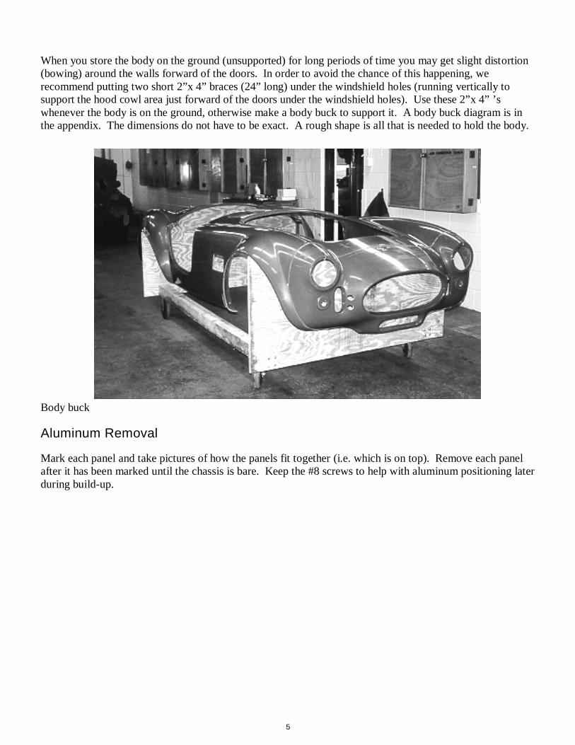
When you store the body on the ground (unsupported) for long periods of time you may get slight distortion (bowing) around the walls forward of the doors. In order to avoid the chance of this happening, we recommend putting two short 2”x 4” braces (24” long) under the windshield holes (running vertically to support the hood cowl area just forward of the doors under the windshield holes). Use these 2”x 4” ’s whenever the body is on the ground, otherwise make a body buck to support it. A body buck diagram is in the appendix. The dimensions do not have to be exact. A rough shape is all that is needed to hold the body.
Body buck
Aluminum Removal
Mark each panel and take pictures of how the panels fit together (i.e. which is on top). Remove each panel after it has been marked until the chassis is bare. Keep the #8 screws to help with aluminum positioning later during build-up.

6

7
Front upper control arm
Vise, Thread locker, ⅜”, ¾” wrench, ¾” socket, Torque wrench IFS components The bolts and no flange locknuts for the rear bolt location are packed with the spindles. Unpack the upper control arm assembly.

8
Put thread locker on the upper balljoint threads.
Screw the upper ball joints into the control arms so that the balljoint angles out on the bottom
9
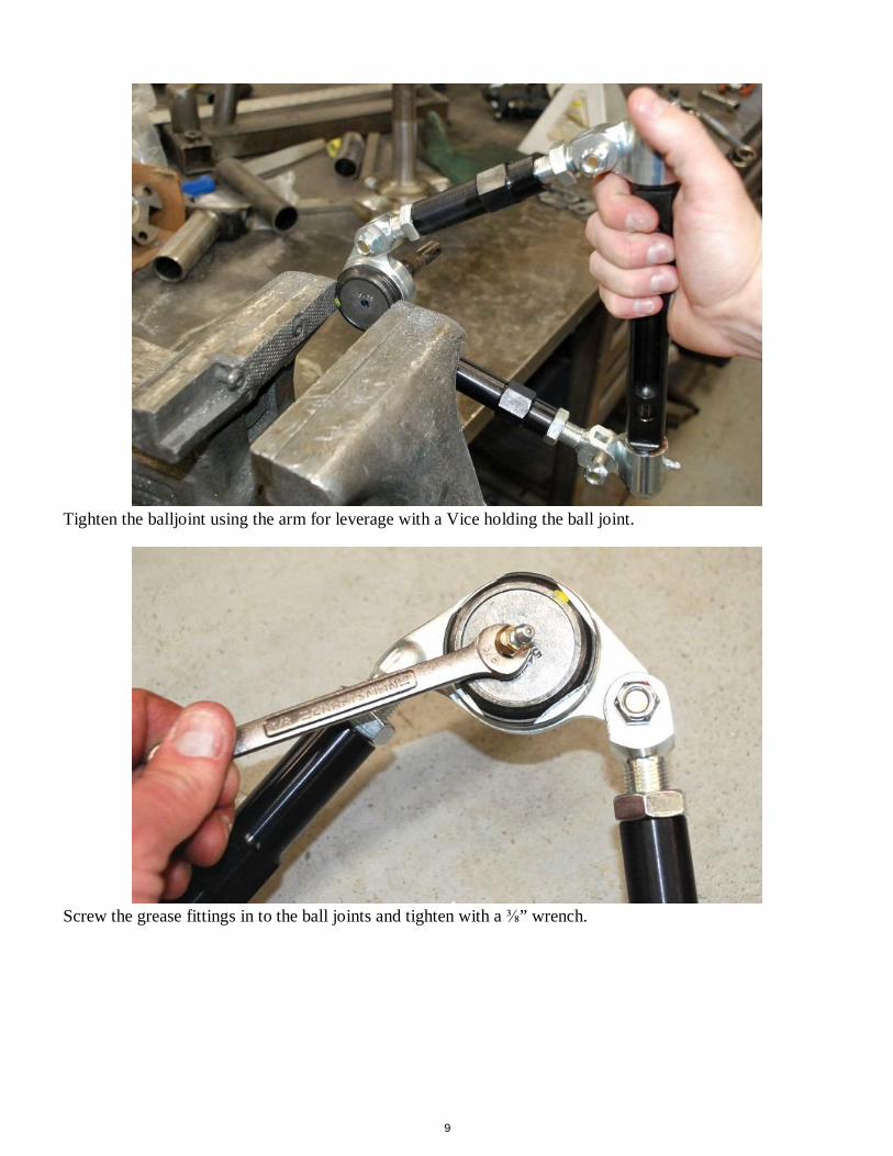
Tighten the balljoint using the arm for leverage with a Vice holding the ball joint.
Screw the grease fittings in to the ball joints and tighten with a ⅜” wrench.

10
Mount the upper control arms to the chassis. Use the mount holes that are vertical on the side of the 2”x 3” tube, not the top horizontal ones.
The bolts and lock nuts for the rear control arm mount are packed with the spindles.
The locknut without the flange is used on the rear mounting hole.
Torque the two bolts that hold the arm to the frame to 135-149Nm (100-110 lbft). Adjusting the upper control Arm
Use the diagram below for reference.

11
Slightly loosen the three pivot bolts using a ⅝” and 11/16” wrench. The Pivot Bolts must be loosened while the car is being aligned and retightened afterwards Loosen the jam nuts on both ends of each adjusting tubes using a 1⅛” wrench. Turn the adjusting tubes to lengthen or shorten the arm. After you have adjusted the arm to the desired length, tighten down the jam nuts against the adjusting tubes, and then tighten each of the three pivot bolts. Torque the pivot bolts to 42 lbft. Grease both ends using chassis grease frequently to insure smooth, trouble free operation. There should never be more than 1” of thread showing past the tightened down jam nuts on either end
of both adjusting tubes.
12
Optional Independent Rear Suspension – Standard width
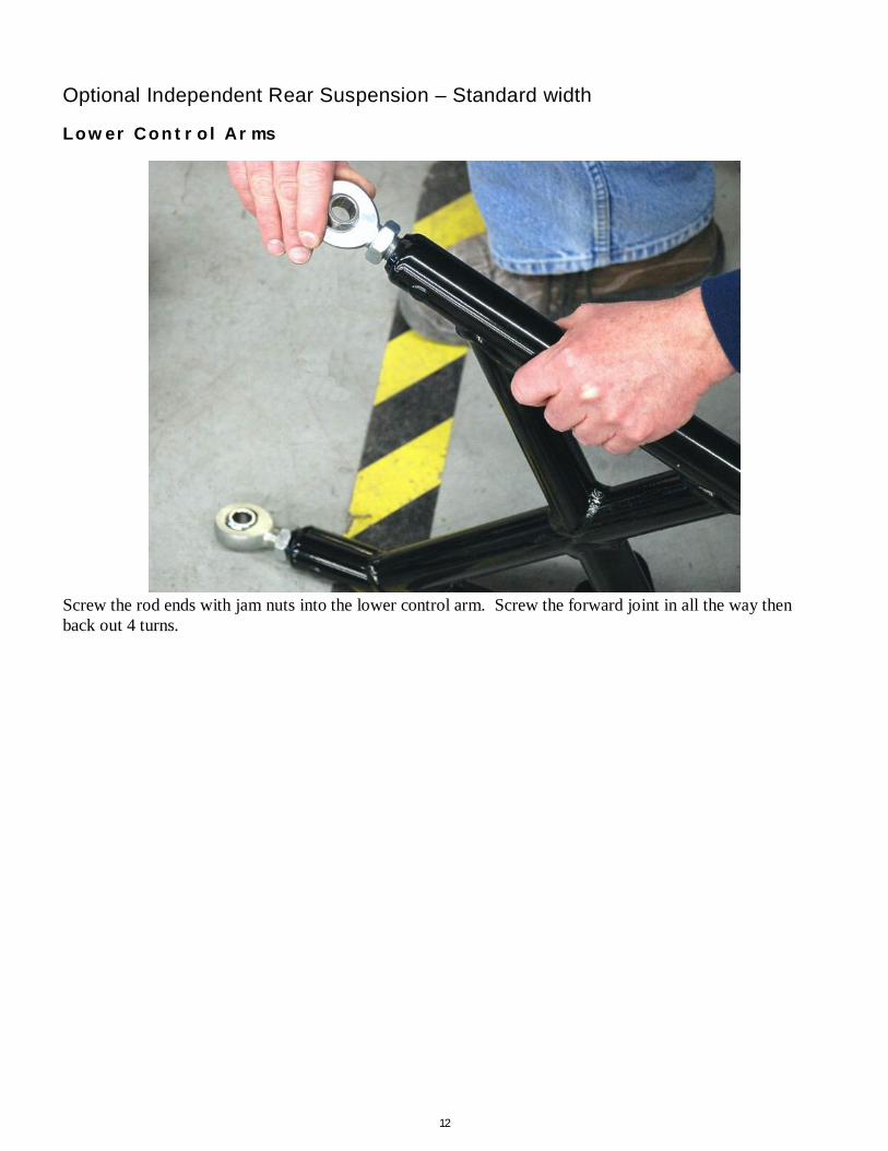
Lower Control Arms
Screw the rod ends with jam nuts into the lower control arm. Screw the forward joint in all the way then back out 4 turns.
13
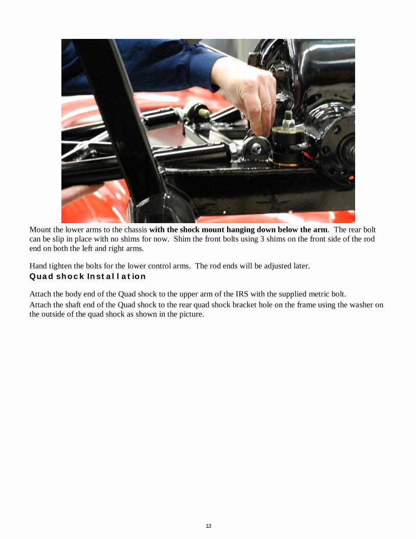
Mount the lower arms to the chassis with the shock mount hanging down below the arm. The rear bolt can be slip in place with no shims for now. Shim the front bolts using 3 shims on the front side of the rod end on both the left and right arms.
Hand tighten the bolts for the lower control arms. The rod ends will be adjusted later. Quad shock Installation
Attach the body end of the Quad shock to the upper arm of the IRS with the supplied metric bolt. Attach the shaft end of the Quad shock to the rear quad shock bracket hole on the frame using the washer on the outside of the quad shock as shown in the picture.

14
Quadshock mounted to frame bracket.
Rear Calipers and Rotors
Push the slotted rotor onto the spindle. Attach the caliper to the spindle using the OEM T-Bird bolts. Torque specs
Item Nm Lbft Lower control arm to frame 135-149 100-110 Upper control arm to frame 135-149 100-110 Lower control arm to Spindle 113-149 83-110 Upper control arm to Spindle 113-149 83-110 Quad shock to upper control arm 75-81 55-60 Quad shock to Spindle 75-81 55-60 Spindle CV nut 245-270 180-200
Firewall & Driver Front Footbox Aluminum
The Footbox front for the Wilwood Pedal box is packaged with the pedalbox in the kit. The one that is shipped on the chassis is for the OEM Mustang pedalbox.

15
Pedal Box
Accelerator Pedal
Check the full range of the accelerator pedal travel to ensure that there are no interferences with the pedal or travel.
Steering Shaft
If running power steering, do not change the splined adapter in the next step.
87-93 Power steering racks have a different spline than a manual steering rack and the 94-04 Power
rack uses a “Pyramid” shaped end. All of these lower adapters are available from FFR.
Clutch Cable
Thread the firewall adjuster out so that the cable has no play in it.
16
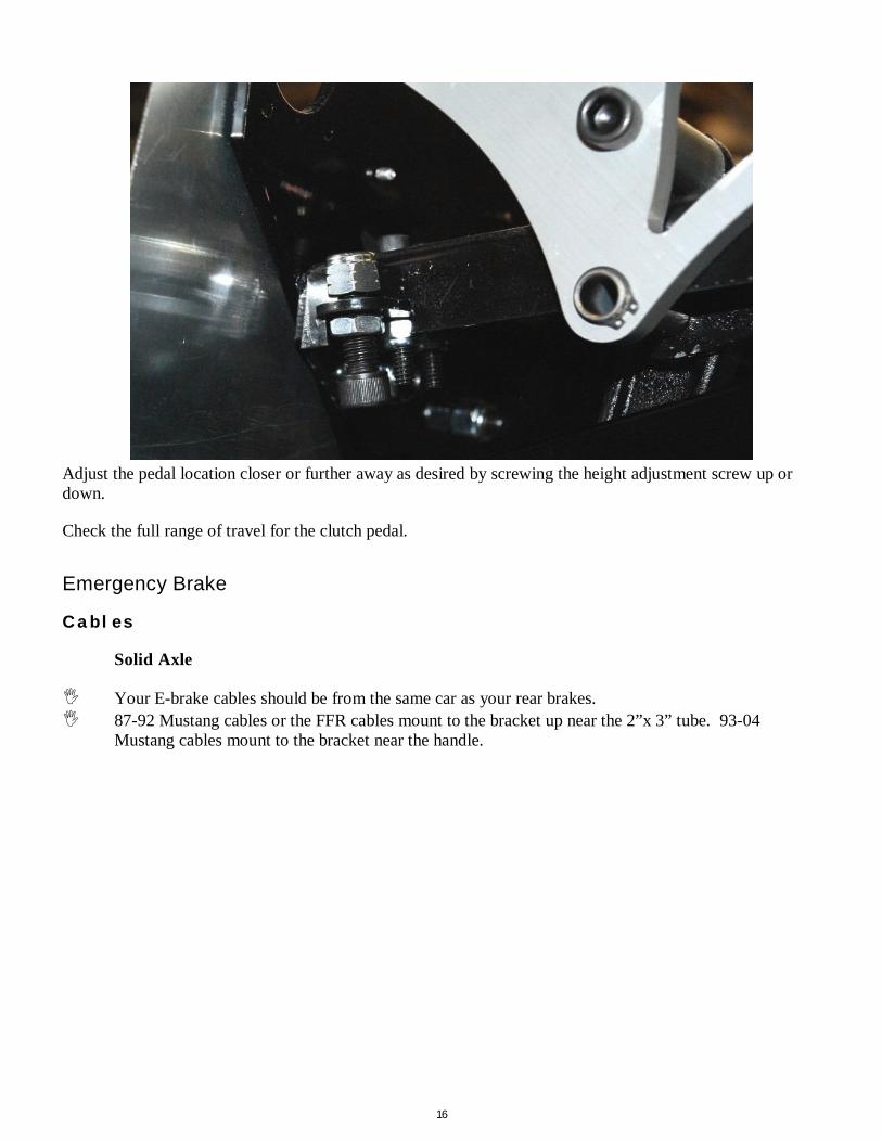
Adjust the pedal location closer or further away as desired by screwing the height adjustment screw up or down.
Check the full range of travel for the clutch pedal.
Emergency Brake
Cables
Solid Axle
Your E-brake cables should be from the same car as your rear brakes. 87-92 Mustang cables or the FFR cables mount to the bracket up near the 2”x 3” tube. 93-04
Mustang cables mount to the bracket near the handle.
17
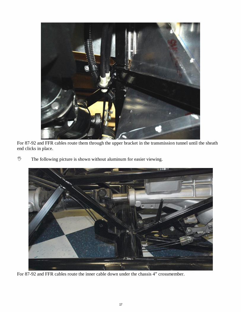
For 87-92 and FFR cables route them through the upper bracket in the transmission tunnel until the sheath end clicks in place.
The following picture is shown without aluminum for easier viewing.
For 87-92 and FFR cables route the inner cable down under the chassis 4” crossmember.

18
Solid Axle
Route the cables back to the calipers and attach. Make sure your routing is out of the way of any moving parts and the cable has slack to move with the axle.
IRS
Bend and route the cables over the center section so that they curves to the rear of the lower control arm and attach the cable to the arm using zip ties from the kit.

19
Emergency brake cable in caliper bracket.
Optional IRS 11.65” brakes

20
Attach the emergency brake cable to the caliper by pulling on the back of the caliper slightly and pushing the cable into the mount. The cable will be very close to or touch the adapter bracket. If necessary, file a small angled recess in the adapter bracket. The caliper floats so it will only get further away from the bracket as the pads wear.
Bend and route the cables over the center section so that they curves to the rear of the lower control arm and attach the cable to the arm using zip ties from the kit.

21
Accelerator Cable
Interior Fitment
Check the full range of the accelerator pedal travel to ensure that there are no interferences with the pedal or travel.
Fuel Tank
9/16” and 5/16” deep sockets, ratchet, 7/16” wrench, rubber mallet, hammer, marker, punch or flathead screwdriver, 3/16”, 5/16” hex key, floor jack, friend, WD 40 or other light lubricant, drill, ¼” drill bit.
OEM Fuel tank components, Secondary Body Fasteners Assembly, Fuel strap fasteners, fuel line components, fuel lines.
Unpack the fuel strap fasteners.

22
Unpack the ¾” square plastic end caps from the secondary body fasteners.
Unpack the OEM fuel tank components including the tank and straps.
Fuel Tank Vent
¼”, 5/16” sockets, ratchet, (2) 1” wrenches, Teflon tape, razor knife

23
Wrap the vent with Teflon tape
Screw the vent into the plastic bushing and tighten.
24
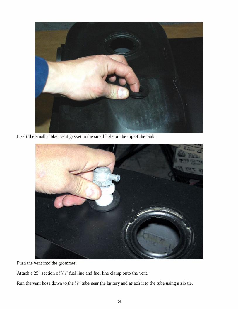
Insert the small rubber vent gasket in the small hole on the top of the tank.
Push the vent into the grommet.
Attach a 25” section of 5/16” fuel line and fuel line clamp onto the vent.
Run the vent hose down to the ¾” tube near the battery and attach it to the tube using a zip tie.
25
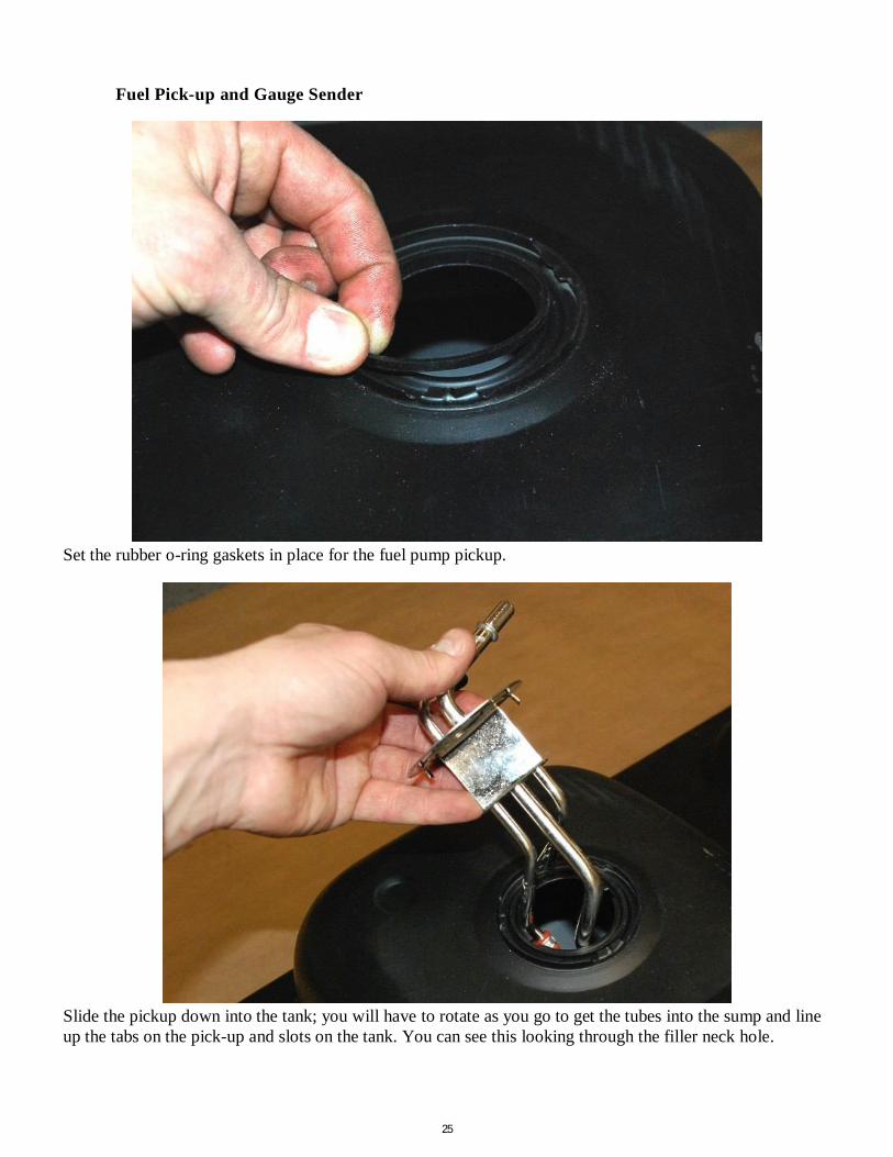
Fuel Pick-up and Gauge Sender
Set the rubber o-ring gaskets in place for the fuel pump pickup.
Slide the pickup down into the tank; you will have to rotate as you go to get the tubes into the sump and line up the tabs on the pick-up and slots on the tank. You can see this looking through the filler neck hole.

26

27
With the pickup all the way down slide the mounting collar and tap tightly into place with a punch and hammer.
Make sure that the lock ring is held by all three locking tabs on the tank or the sender will leak.
Repeat this process for the level sender.
Make sure that the lock ring is held by all three locking tabs on the tank or the sender will leak.
28
Brake System
Tube bender, 3/16”, ¼”, 7/16”, ⅝” drill bits, drill, rivet gun, marker, tape measure, razor knife, round file or sand paper, brake fluid.
Pedal Components, Insulated clip hardware, Brake line components, 3/16” brake lines, Front caliper/rotor assembly
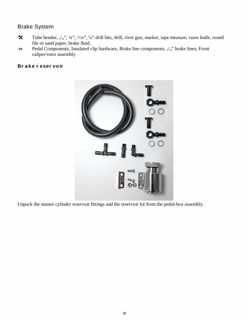
Brake reservoir
Unpack the master cylinder reservoir fittings and the reservoir kit from the pedal-box assembly.
29
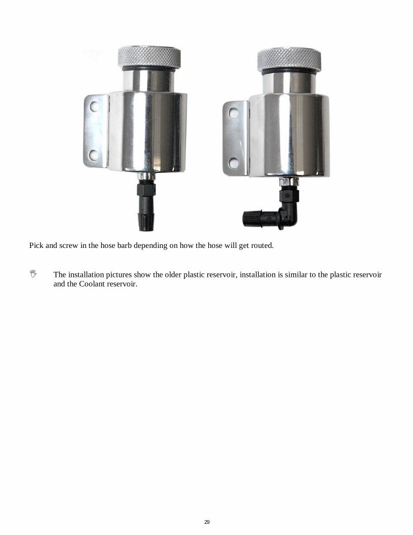
Pick and screw in the hose barb depending on how the hose will get routed.
The installation pictures show the older plastic reservoir, installation is similar to the plastic reservoir
and the Coolant reservoir.
30
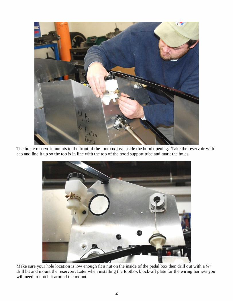
The brake reservoir mounts to the front of the footbox just inside the hood opening. Take the reservoir with cap and line it up so the top is in line with the top of the hood support tube and mark the holes.
Make sure your hole location is low enough fit a nut on the inside of the pedal box then drill out with a ¼” drill bit and mount the reservoir. Later when installing the footbox block-off plate for the wiring harness you will need to notch it around the mount.

31
Drill a ⅝” hole one inch down from the bottom of the reservoir. This hole is for the fluid line to run through so take extra time with a file and round all the edges making sure there are no burrs left or sharp spots.
Route the fluid line for the master cylinders through the hole and press onto the bottom of the reservoir.
32
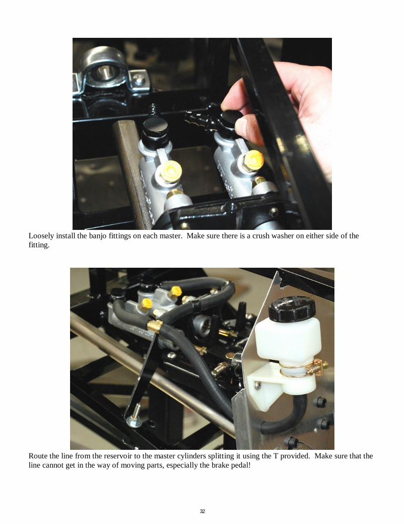
Loosely install the banjo fittings on each master. Make sure there is a crush washer on either side of the fitting.
Route the line from the reservoir to the master cylinders splitting it using the T provided. Make sure that the line cannot get in the way of moving parts, especially the brake pedal!
33
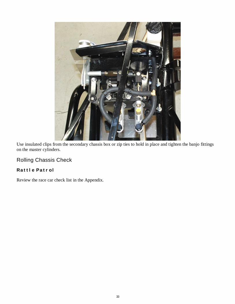
Use insulated clips from the secondary chassis box or zip ties to hold in place and tighten the banjo fittings on the master cylinders.
Rolling Chassis Check
Rattle Patrol
Review the race car check list in the Appendix.
34
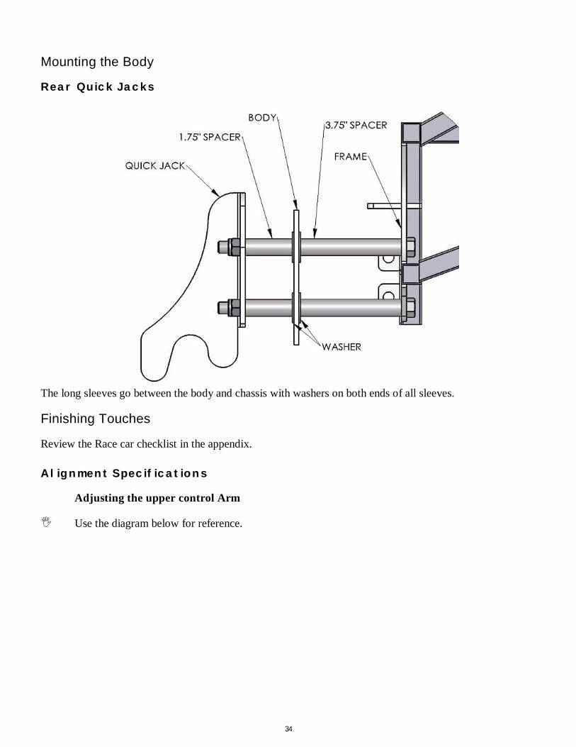
Mounting the Body
Rear Quick Jacks
The long sleeves go between the body and chassis with washers on both ends of all sleeves.
Finishing Touches
Review the Race car checklist in the appendix. Alignment Specifications
Adjusting the upper control Arm
Use the diagram below for reference.

35
Slightly loosen the three pivot bolts using a ⅝” wrench and socket. Loosen the jam nuts on both ends of each adjusting tubes using a 1⅛” wrench. Turn the adjusting tubes to lengthen or shorten the arm. After you have adjusted the arm to the desired length, tighten down the jam nuts against the adjusting tubes, and then tighten each of the three pivot bolts. Torque the pivot bolts to 42 lbft. Grease both ends using chassis grease frequently to insure smooth, trouble free operation. There should never be more than 1” of thread showing past the tightened down jam nuts on either end
of both adjusting tubes. The Pivot Bolts must be loosened while the car is being aligned and retightened afterwards
Optional Parts
Check out factoryfive.com for the latest options available. Instructions are available in the parts catalog at www.factoryfiveparts.com
Performance Reference Material and Technical Support Maintenance
Check the items on the race car check sheet in the Appendix on a yearly basis or before track days depending on how hard the car is driven.
Templates

36

37
Appendix D – Race car check sheet

38
CAR_______________________________________ Date___________ Steering Steering wheel tight ___ Universal joint set screws tight ___ Rack mount bolts tight ___ Tie rod ends tight ___ Tie rod to spindle bolts tight ___ Steering free lock to lock ___ Front Suspension Ride height ___ Front wheel bearings tight ___ Upper and lower ball joints tight with cotter pins ___ Upper control arm bolts tight ___ Upper control arm jam nuts and clevis nuts tight ___ Lower control arm bolts tight ___ Shock mounting bolts tight ___ Spring collars taped/tight ___ Tire pressure set (recommend 22-25 psi) ___ Lug nuts tight (90 lb-ft) ___ Brakes Front Caliper bolts tight ___ Rear caliper bolts tight ___ Rotors clean no cracks or groves ___ Brakes bled/bleeders tight ___ No leaks under pressure ___ Master cylinder bolts tight ___ Reservoir full ___ Flexible lines tied up and undamaged ___ Cockpit Seat securely bolted ___ Harnesses securely bolted ___ Harnesses free from cuts or abrasions ___ Pedals travel freely and bolts secure ___ Throttle return springs hooked up ___ Brake push rod secure and clip tight ___ Interior wiring tight ___ Shifter tight and free ___ Mirrors tight and adjusted ___ Windshield side bar screws tight ___ Inspection/registration up to date ___ Electrical
39
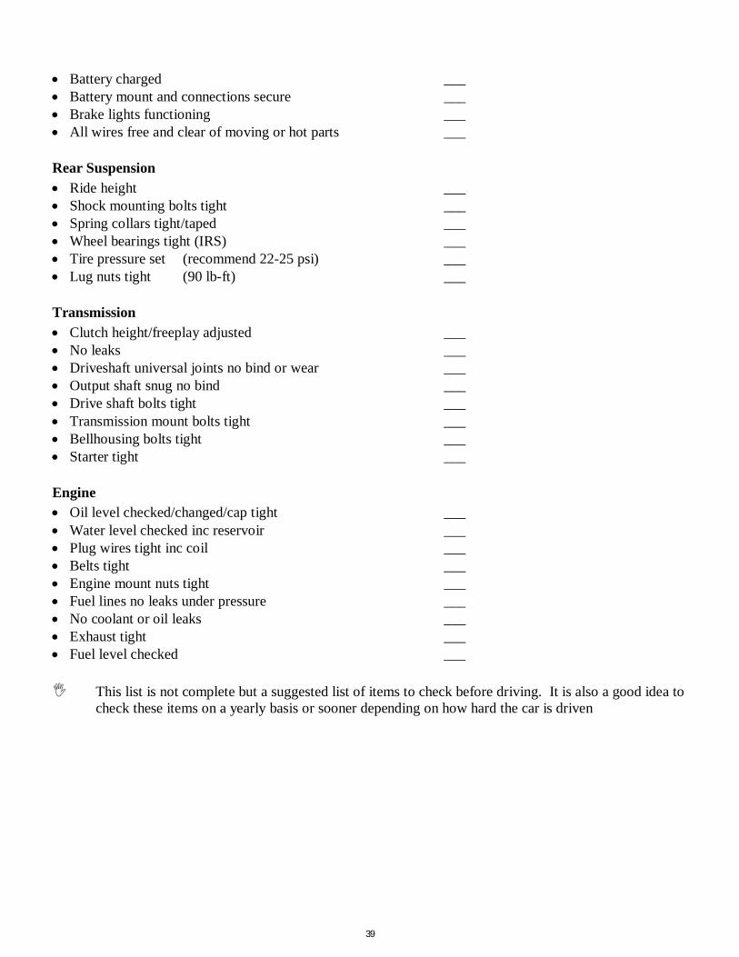
Battery charged ___ Battery mount and connections secure ___ Brake lights functioning ___ All wires free and clear of moving or hot parts ___ Rear Suspension Ride height ___ Shock mounting bolts tight ___ Spring collars tight/taped ___ Wheel bearings tight (IRS) ___ Tire pressure set (recommend 22-25 psi) ___ Lug nuts tight (90 lb-ft) ___ Transmission Clutch height/freeplay adjusted ___ No leaks ___ Driveshaft universal joints no bind or wear ___ Output shaft snug no bind ___ Drive shaft bolts tight ___ Transmission mount bolts tight ___ Bellhousing bolts tight ___ Starter tight ___ Engine Oil level checked/changed/cap tight ___ Water level checked inc reservoir ___ Plug wires tight inc coil ___ Belts tight ___ Engine mount nuts tight ___ Fuel lines no leaks under pressure ___ No coolant or oil leaks ___ Exhaust tight ___ Fuel level checked ___ This list is not complete but a suggested list of items to check before driving. It is also a good idea to
check these items on a yearly basis or sooner depending on how hard the car is driven