factory 6-speed tapered roller bearing...
TRANSCRIPT

PV1-117139
Factory 6-Speed Tapered Roller Bearing Kit
Installation Instructions
www.bakerdrivetrain.com
PV1-117139
PAGE 1
TABLE OF CONTENTS
1. Introduction and Fitment
2. Required Parts, Tools, and Reference Materials
3. Included Parts
4. Tapered Roller Bearing Exploded View
5. Torque Specifications and Stock Component Removal
6. Transmission Case Preparation
7. Countershaft Bearing Removal
8. Countershaft Bearing Installation
9. Tapered Roller Bearing Adapter Installation
10. Tapered Roller Bearing Adapter Installation
11. Tapered Roller Bearing Adapter Installation
12. Main Drive Gear Installation
13. Main Drive Gear Installation
14. Main Drive Gear Installation
15. Main Drive Gear Installation
16. Finish Line
17. Terms & Conditions
18. Notes
INTRODUCTION
BAKER R&D started the design and development process of the GrudgeBox in early 2016. As
the design progressed the youngest and most inexperienced member of the group was
disturbed by something that the others failed to see until one day he said, “Isn’t the strength of
any system only as good as the weakest link?”. After much profanity and embarrassing public
outbursts Bert proclaimed, “He’s right!”. So began the development of the tapered roller main
drive gear bearing for the GrudgeBox.
Word of this leaked out of the R&D department and soon the calls started coming in. Some
inquiries were hostile in nature. The decision was made to offer the crown jewel of the
GrudgeBox to those with a stock 2007-later transmission.
Tapered roller bearings can be found in lathes, 18-wheeler trailer axles, and the left side
flywheels on Milwaukee engines from the last century. To machinists, truckers, and seasoned
Harley techs, tapered roller bearings are the last word in durability and strength, and we proudly
make them available for late model Big Twins.
FITMENT
• 2006-Later Dyna, Factory 6-Speed Transmission
• 2007-Later Softail, Factory 6-Speed Transmission
• 2007-Later Touring, Factory 6-Speed Transmission
FACTORY 6-SPEED TAPERED ROLLER BEARING KIT

PV1-117139
PAGE 2
REQUIRED PARTS, TOOLS, & REFERENCE MATERIALS
To install the Factory 6-Speed Tapered Roller Bearing Kit, the following is required:
• Factory Service Manual for your year and model motorcycle
• New primary cover gasket
• Common hand tools (allen wrenches, sockets, retaining ring pliers, etc.)
• Healthy breaker bar, 1/2" drive
• Torque wrenches, 3/8” & 1/2” drive
• 1-3/16” socket, 6 pt.
• Red and blue threadlocker
• Dial indicator
• MAP/Propane gas or heat gun
• Transmission case bearing service tool – included with your kit
o BAKER TOOLE-GB
• Main drive gear & bearing service tool
o BAKER TOOLA-07
o H-D equivalent 35316C
• Inner primary race service tool
o BAKER TOOLB-56
o H-D equivalent 34902B
• Pulley locking tool
o BAKER TOOLC-56
o H-D equivalent 46282
• Pulley nut socket
o BAKER TOOLD-07
o H-D equivalent 47910
• Primary drive locking tool
o H-D-48219 (Touring models)
o H-D-47977 (Softail/Dyna)
• Primary fluid, 40-46 oz.; see Factory Service Manual
o BAKER recommends Spectro Heavy Duty Primary Chain Case Oil; R.HDPCO
• Transmission fluid, 32 oz.
o BAKER recommends Spectro Heavy Duty Platinum 6 Speed Transmission Oil;
BD-75140-32
HIGHLY RECOMMENDED ADDITIONAL PART
BAKER highly recommends that the automatic chain tensioner
be replaced with a 177-67K Armored Attitude Adjuster (figure 1).
Extensive testing and durability miles have proven that the
177-67K Armored Attitude Adjuster puts less shear stress load
on the motor sprocket shaft and the transmission mainshaft,
thereby extending the life of the drivetrain components.
FACTORY 6-SPEED TAPERED ROLLER BEARING KIT
WHAT DO I NEED?
WARRANTY
This product includes a 2-year,
24,000-mile warranty. All steps
in these instructions, including
replacement of the countershaft
bearing, must be completed for
the warranty to remain valid.
FIGURE 1 | BAKER ARMORED
ATTITUDE ADJUSTER

PV1-117139
PAGE 3
Transmission Case Bearing Service Tool, TOOLE-GB
Bearing Door Gasket, 35654-67 Top Cover Gasket, 34917-06-F Side Cover Gasket, 36805-06-F
Factory 6-Speed Main Drive Gear Assembly - H-D Main Drive Gear, Modified, 35122-CD6 (Includes bearings and seals) - Tapered Roller Bearing, HR32910J - .104” Bearing Spacer, Green, 11620-GB
WHAT’S IN MY KIT?
Countershaft Bearing, 8963 Tapered Roller Bearing, HR32910J Tapered Roller Bearing Adapter, 11610-GB Pulley Spacer w/ O-Ring, 33334-GB | OR568M52 Main Drive Gear Seal, 12074-67 85mm Beveled Internal Retaining Ring, VHO-334STPA .102” Bearing Spacer, White 11615-GB .106” Bearing Spacer, Blue 11625-GB

PV1-117139
PAGE 4
ITEM P/N QTY DESCRIPTION
1 5M-GBS 1 5th Gear, Mainshaft, 32T, Helical (Shown)
5M-GBW 1 5th Gear, Mainshaft, 31T, Spur
2 OR568132 1 O-Ring, Buna #132
3 HR32910J 2 Bearing, Tapered Roller, 50 x 72 x 15mm
4 11610-GB 1 Adapter, Tapered Roller Bearings
5 11615-GB 1 Spacer, Tapered Roller Bearings, .102”, White
11620-GB 1 Spacer, Tapered Roller Bearings, .104”, Green
11625-GB 1 Spacer, Tapered Roller Bearings, .106”, Blue
6 OR568M52 1 O-ring, Pulley / Sprocket Spacer, 52mm
7 33334-GB 1 Spacer, Pulley / Sprocket
8 1302-334PP 1 Retaining Ring, Beveled Internal, 85mm
9 12074-67 1 Seal, Main Drive Gear, 2.380” x 3.375” x .285”
TAPERED ROLLER BEARING EXPLODED VIEW
FIGURE 2 | EXPLODED VIEW, TAPERED ROLLER BEARING
*** .104” spacer (green) is pre-installed on main drive gear ***
*** .102” (white) and .106” (blue) spacers are included separately in your kit ***

PV1-117139
PAGE 5
BEFORE YOU DO A DAMN THING
Know the following. The transmission is a component in the powertrain of your motorcycle. As
such, it’s function is highly dependent on other components in the powertrain to perform as
designed. If the clutch, clutch actuator, primary, or shift linkage is worn, tired, or compromised in
any way, the transmission will not perform as designed. The process of installing the Tapered
Roller Bearing Kit is the perfect time to assess and freshen up these components to ensure the
transmission gives you years of trouble-free service.
TORQUE SPECIFICATIONS
THREAD APPLICATION TORQUE VALUE THREADLOCKER
Side cover, top cover, derby
1/4"-20 cover, outer primary, VSS, 125 – 135 in-lb Blue recommended
pulley locking plate
5/16”-18 Bearing door, inner primary 22 – 25 ft-lb Blue recommended
5/16”-24 Shift arm pinch bolt 18 – 22 ft-lb Blue recommended
9/16”-12 BAKER comp sprocket bolt 150 ft-lb Red required
9/16”-12 H-D comp sprocket bolt See Factory Service Manual Red required
3/4”-18 Clutch nut 70 – 80 ft-lb Red required
1-3/4”-20 Pulley nut 35 ft-lb + 35° – 45° Red required
9/16”-18 Neutral switch 120 – 180 in-lb None
3/4”-16 Transmission dipstick 25 – 75 ft-lb None
1/2”-20 Transmission drain plug 14 – 21 ft-lb None
1/2”-20 Primary drain plug 14 – 21 ft-lb None
STOCK COMPONENT REMOVAL
Refer to your Factory Service Manual for detailed instructions on how to remove your stock
gearset and main drive gear from the transmission case. Softails, Dynas, and Touring models
are all different configurations and require different methods to accomplish the removal. Ensure
that you have the correct Factory Service Manual for your year, make, and model of motorcycle.
BERT TIPS:
Apply heat to the comp sprocket bolt head prior to removal. Failure to do so could result
in mangled sprocket shaft threads and halt the installation of your Tapered Roller
Bearing Kit.
Remove the dipstick prior to removing the gearset from the transmission case. Failure to
do so will result in a broken dipstick and a trip to the nearest H-D dealer.
INSTALLATION PREPARATION
PV1-117139
PAGE 6
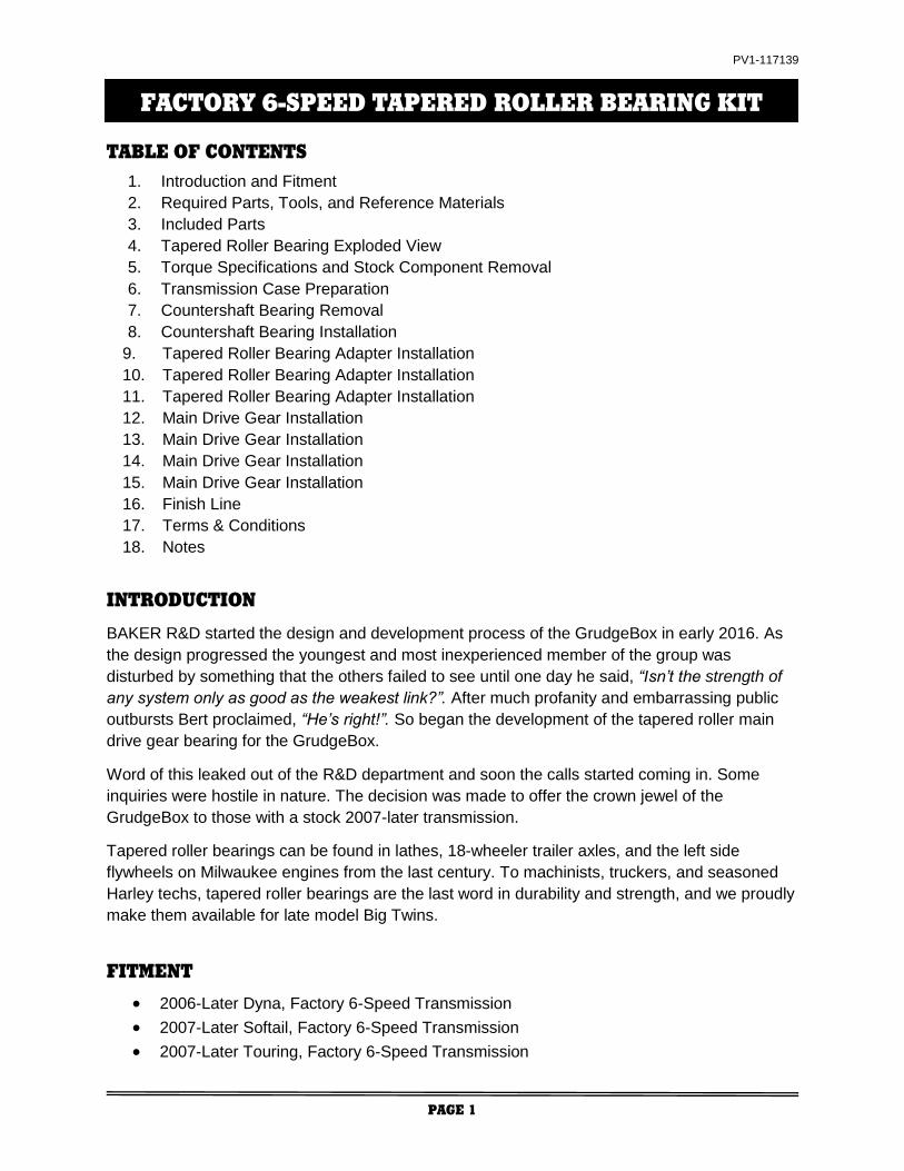
TRANSMISSION CASE PREPARATION
Surgically clean the left side of the transmission case in preparation for installing the new
Tapered Roller Bearing Kit. This surgical cleansing includes the main drive gear and
countershaft bearing boss areas, the three inner primary mount bosses, and the shifter pawl
boss. See figure 3.
The bearing boss areas need to be clean so the bearing bores are not scored by dirt or debris
during the removal of old bearings and installation of new ones. The three inner primary mount
bosses need to be clean so the TOOLE-GB plate registers flat on the left side transmission
case.
CAUTIONARY NOTE:
There are special tools available from other manufacturers that remove and install the countershaft
bearing but they all have one fundamental error in common. That is, they push on the inside of the
cup shaped countershaft bearing (from right to left in the motorcycle) for removal and installation.
THIS IS WRONG! “Cup bearings”, as they are sometimes called, require that the installation force
be applied to the outside of the ‘cup’. The BAKER TOOLE-GB (provided in this kit) applies removal
and installation force on the outside of the cup (from left to right).
Keep in mind that TOOLE-GB serves two functions. Removal and installation of the countershaft
cup bearing AND installation of the main drive gear tapered roller bearing adapter.
You are now ready to remove the old countershaft bearing and replace it with the new one (8963,
provided in this kit). Use TOOLE-GB and follow the instructions on the next pages.
FIGURE 3 | SURGICALLY CLEAN THE LEFT SIDE OF THE TRANSMISSION CASE IN THE AREAS INDICATED ABOVE
INSTALLATION PREPARATION
PV1-117139
PAGE 7
COUNTERSHAFT BEARING REMOVAL
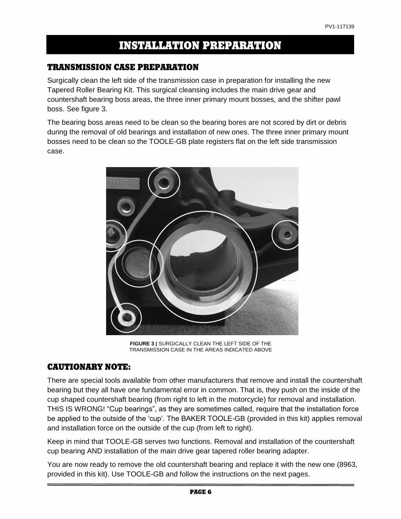
2. With the cup (9) centered on the
countershaft bearing, finger
tighten the nut (5) and cap
screws (10). Secure the cap
screws (10) with an allen wrench.
Hold the threaded shaft (2) with a
9/16” combo wrench or 5/16”
allen wrench. Press the
countershaft bearing through the
case by tightening the nut (5)
against the washer (6) and case
support plate (1); see figure 6.
FIGURE 4 | POSITIONAL RELATIONSHIPS OF TOOLE-GB COMPONENTS RELATIVE TO THE LEFT SIDE (PRIMARY SIDE) OF
TRANSMISSION CASE
FOR COUNTERSHAFT BEARING REMOVAL AND INSTALLATION,
SUPPORT PLATE IS LOCATED AS SHOWN WITH COUNTERBORE POCKET
AND ENGRAVING FACING THE CASE
FIGURE 5 | SUPPORT PLATE POSITION FOR COUNTERSHAFT BEARING REMOVAL AND INSTALLATION
FIGURE 6 | COUNTERSHAFT BEARING IS PUSHED WITH THE TOOL CUP FROM LEFT
TO RIGHT FOR REMOVAL
1. Reference figures 4 and 5 for
the positional relationships of
the TOOLE-GB components
required to remove the
countershaft bearing from the
case. Loosely assemble the
support plate (1) with spacers
(8), cap screws (10), threaded
shaft (2), and cup (9). Push the
cup (9) onto the O-ring end of
the threaded shaft (2) until it
snaps into position.
REPLACING THE COUNTERSHAFT BEARING

PV1-117139
PAGE 8
COUNTERSHAFT BEARING INSTALLATION
3. With the old countershaft
bearing removed, loosen the
nut (5) to allow removal of the
cup (9) from the threaded shaft
(2). Wipe out the countershaft
bearing bore in the case with a
clean rag and apply a thin film
of oil for installing the new
bearing. Install cup (7) on the
end of the threaded shaft (2)
until it fully seats. Place the new
bearing between the cup (7)
and the case as shown in figure
8. Snug the threaded shaft (2)
by hand until the bearing
registers squarely in the bore of
the case; see figure 7.
4. With the new bearing registered
squarely in the case bore, hold
the threaded shaft (2) with a
9/16” combo wrench or 5/16”
allen wrench. Tighten the nut (5)
until the cup (7) is completely
bottomed out on the case to
ensure that the bearing is
installed at the correct depth;
see figure 8. Bearing should be
slightly above the surface of the
case.
BERT TIP:
Do not over tighten the nut (5)
after the cup (7) bottoms on
the case. Doing so will
damage the cup (7).
FIGURE 7 | TOOL CUP APPLIES FORCE TO THE CUP END OF THE
COUNTERSHAFT BEARING
FIGURE 8 | COUNTERSHAFT BEARING INSTALLED WITH TOOLE-GB CUP FLUSH TO LEFT SIDE OF TRANSMISSION CASE
REPLACING THE COUNTERSHAFT BEARING

PV1-117139
PAGE 9
2. Before the cap screws (10) are
threaded into the case, slide the
bearing adapter onto the cup (4).
Snug the cap screws (10) then
loosen one half turn. Snug the
threaded shaft (2) by turning the
nut (5) by hand until the bearing
adapter registers squarely with the
transmission case bore. With the
adapter registered squarely with
the case, loosen the threaded
shaft (2) just enough to allow the
cap screws (10) to be tightened;
see figure 11. FIGURE 11 | BEARING ADAPTER WITH TOOLE-GB
APPLYING FORCE FROM LEFT TO RIGHT
FIGURE 10 | SUPPORT PLATE POSITION FOR BEARING ADAPTER INSTALLATION
TAPERED ROLLER BEARING ADAPTER INSTALLATION
INSTALLING THE TAPERED ROLLER BEARING ADAPTER
1. Reference figures 9 and 10 for
the positional relationships of
the tool components required to
install the tapered roller bearing
adapter into the transmission
case. Loosely assemble the
support plate (1) with spacers
(8), cap screws (10), threaded
shaft (2), and cup (4). Push the
cup (4) onto the O-ring end of
the threaded shaft (2) until it
snaps into position.
FOR BEARING ADAPTER INSTALLATION, SUPPORT PLATE
IS LOCATED AS SHOWN WITH COUNTERBORE POCKET AND
ENGRAVING FACING THE CASE
FIGURE 9 | POSITIONAL RELATIONSHIP OF TOOLE-GB COMPONENTS FOR TAPERED
ROLLER BEARING ADAPTER INSTALLATION
PV1-117139
PAGE 10
INSTALLING THE TAPERED ROLLER BEARING ADAPTER
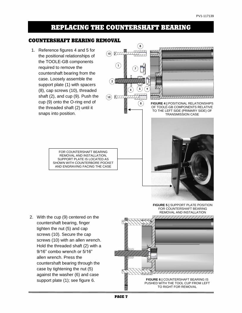
3. The tapered roller bearing adapter
is a press fit into the transmission
case unlike the H-D bearing which
has a slip-fit. To ensure successful
installation of the bearing adapter
and longevity of the installation tool,
you must heat the transmission
case as shown in figure 12. Use a
MAP/propane torch or a heat gun
as shown in figure 13.
4. Apply heat evenly around the boss
of the main drive gear bearing
bore from the outside of the case
as shown in figure 12. DO NOT
heat the boss from the inside of
the case (this could damage your
speedometer sensor) and keep
heat away from the bearing
adapter that is staged and ready
for installation. The bearing bore
boss should be heated to
approximately 200 – 250°F.
FIGURE 12 | APPLY HEAT AROUND THE MAIN DRIVE GEAR BEARING BOSS AREA
FIGURE 13 | USE MAP/PROPANE GAS OR A HEAT GUN

PV1-117139
PAGE 11
FIGURE 16 | BEVELED RETAINING RING WITH BEVEL FACING OUTWARD
INSTALLING THE TAPERED ROLLER BEARING ADAPTER
BEVEL ON RETAINING RING MUST FACE OUTWARD
5. Immediately after the case is heated,
secure the 9/16” hex or 5/16” allen end of
the threaded shaft (2) and tighten the nut
(5) to drive the bearing adapter into the
case until it bottoms out in the bore; see
figure 14. This operation must be done
quickly with no interruptions while the
case is warm.
BERT TIP:
Do not over tighten the nut (5) after
the bearing adapter is bottomed out.
Doing so may damage the tool or
main drive gear bearing bore landing
in the case.
6. Remove the installation tool. You will
know the bearing adapter is seated into
the bore when the beveled retaining ring
groove is fully visible and the retaining
ring fully seats into the groove; see
figure 15.
7. Install the beveled retaining ring
(VHO-334STPA) with the bevel
facing outward; see figure 16.
FIGURE 14 | BEARING ADAPTER FULLY SEATED IN CASE
FIGURE 15 | BEARING ADAPTER VISUAL INSPECTION

PV1-117139
PAGE 12
1. After installing the retaining ring, put a
thin coating of oil on both bearing races
located in the adapter. We recommend
a light spray lubricant like WD-40®; see
figure 17. A thicker oil could give you a
false reading when checking endplay.
So far in the tapered roller bearing
installation process, everything has
been pretty much like servicing a stock
bike, but that’s going to change right
now. Setting up end play in the tapered
roller bearings is NOT a task for
someone whose only experience is
changing turn signal bulbs. If anything
so far in this process has tested your
wrenching aptitude, now is a good time
to turn the job over to seasoned
wrench, preferably one who has
experience setting up the tapered
rollers in the left side of the motor case.
2. The kit comes with three spacers for
setting up endplay in the tapered
roller bearings: .102” (white), .104”
(green) and .106” (blue) thick. The
most commonly used spacer (.104”)
is pre-installed on the main drive
gear. The .102” and .106” spacers
are in your kit if they are required
after the end play is measured with
the pre-installed .104” spacer.
Before installing the main drive gear,
put a thin coating of transmission oil
on the O-ring; see figure 18.
MAIN DRIVE GEAR INSTALLATION
INSTALLING THE MAIN DRIVE GEAR
FIGURE 17 | LIGHTLY OIL BOTH BEARING RACES AFTER INSTALLING THE TAPERED ROLLER BEARING ADAPTER
FIGURE 18 | MAIN DRIVE GEAR WITH BEARING SPACERS

PV1-117139
PAGE 13
3. Follow the Factory Service Manual
to install the main drive gear using
BAKER TOOLA-07 or H-D
equivalent 35316C. If the H-D
equivalent tool is used, you will need
to use the pulley spacer 33334-GB
from your tapered roller bearing kit
for extra spacing while pressing the
tapered roller bearings together.
If you need to use the pulley spacer
(33334-GB), temporarily remove the
O-ring. Remember to re-install it after
the end play is set.
4. Gently slide the assembled main drive
gear through the case. Take the loose
tapered roller bearing (HR32910J) and
slide it over the main drive gear, letter
side facing out. Slide the pulley spacer
onto the gear if needed (O-ring groove
facing bearing), followed by the
remaining press tools; see figure 19.
INSTALLING THE MAIN DRIVE GEAR
5. With the tooling installed, snug the
assembly by hand while making sure
the installation tool cup is properly
aligned and not skewed to the side of
the tapered roller bearing. Hold the
bolt on the inside of the case using the
proper socket and ratchet. Tighten the
main drive gear tooling on the primary
side of the bike until it is fully seated
and tight. Refer to the main drive gear
tool instructions and figure 20.
FIGURE 19 | IF USING H-D TOOLING, PULLEY SPACER IS NEEDED TO EXTEND THE LENGTH OF THE INSTALLATION CUP
FIGURE 20 | INSTALLING THE MAIN DRIVE GEAR

PV1-117139
PAGE 14
FIGURE 21 | CHECKING AXIAL ENDPLAY IN THE MAIN DRIVE GEAR TAPERED ROLLER BEARINGS
INSTALLING THE MAIN DRIVE GEAR
6. Do not remove the install tool yet; leave
everything tight. Measure the amount of
endplay in the main drive gear
assembly using a dial indicator as
shown in figure 21. Total axial endplay
(pulling / pushing on the gear) must be
between .0005” and .003”. Measuring
end play is tricky. The end play
measurement can easily be skewed if
radial (up-and-down, side-to-side) or
rotational forces are applied, so Bert
says, “DON’T DO THAT!”. Old timers
that have experience setting up left side
motor case end play can do so without
a dial indicator. Instead, they rely on
feel and sound. A correctly set up main
drive gear with tapered roller bearings
should make a soft ‘tunk-tunk-tunk’
sound when axial loads are applied.
IF YOUR SETUP IS TOO TIGHT (UNDER .0005”), REMOVE THE MAIN DRIVE
GEAR FROM THE CASE USING THE PROPER TOOLING. REMOVE THE O-RING
FROM THE ‘SNOUT’ OF THE MAIN DRIVE GEAR FOLLOWED BY THE .104”
(GREEN) SPACER. INSTALL THE .106” (BLUE) SPACER, REPLACE THE O-RING,
AND GO BACK TO STEP 4.
IF YOUR SETUP IS TOO LOOSE (OVER .003”), REMOVE THE MAIN DRIVE GEAR
FROM THE CASE USING THE PROPER TOOLING. REMOVE THE O-RING FROM
THE ‘SNOUT’ OF THE MAIN DRIVE GEAR FOLLOWED BY THE .104” (GREEN)
SPACER. INSTALL THE .102” (WHITE) SPACER, REPLACE THE O-RING, AND
GO BACK TO STEP 4.
7. Remove the tooling used to install the main drive gear along with pulley spacer if you had
to use it. If necessary, reinstall the O-ring (OR568M52) that you removed from the pulley
spacer in step 4.

PV1-117139
PAGE 15
FIGURE 22 | INSTALLING THE PULLEY SPACER AND MAIN DRIVE GEAR SEAL
FIGURE 23 | MAIN DRIVE GEAR SEAL INSTALLED FLUSH WITH CASE
INSTALLING THE MAIN DRIVE GEAR
8. Put some transmission fluid on the
outer diameter and O-ring of the pulley
spacer. Install it onto the main drive
gear with the O-ring facing inward
(toward the bearing); see figure 22.
9. Put some transmission fluid on the lip
of the main drive gear seal and install
it. Make sure the seal is flush with the
transmission case all the way around
the bearing boss; see figure 23.

PV1-117139
PAGE 16
GEARSET INSTALLATION
1. The time has come to stuff the gearset back into the transmission case. Before that is
done, take time to ensure no debris or tarantulas have found their way into the case. Check
that the two hollow dowels are still located in the bearing door and replace the bearing door
gasket with the one provided in this kit.
2. Generously apply transmission fluid to the last 6” of the mainshaft, end of the countershaft,
new countershaft bearing, tapered roller bearings, and the bearings/seal in the main drive
gear.
3. Follow your Factory Service Manual to re-install the stock H-D gearset and side cover. Be
sure to replace the side cover gasket with the one provided in this kit.
TRANSMISSION FLUID
4. Re-install the transmission drain plug and torque it to 14 – 21 ft-lb. Re-install the
transmission dipstick and torque it to 25 – 75 in-lb.
5. Put 32 oz. transmission fluid (75-85W140 synthetic gear oil) into the transmission by
pouring it through the top cover cavity onto the main drive gear and shifter pawl. Make sure
to coat as much of the gearset components as possible with the fluid.
6. Re-install the top cover with the new gasket provided.
FINAL STEPS
7. Button up the primary, exhaust, shift linkage, and floorboards/footpegs per your Factory
Service Manual. Make sure to re-install the primary drain plug and fill the primary with fluid.
8. You have successfully completed the installation of your tapered roller bearing kit. Be
observant of basic transmission function and overall vehicle operation during the first 20
miles. Check for leaks after your first ride. Provided there are no issues, give ‘em hell and
enjoy your new BAKER main drive gear bearing.
FINISH LINE

PV1-117139
PAGE 17
ORDERS
Orders can be pre-paid using VISA, MasterCard, American Express, and Discover or via wire transfer ($30 wire transfer fee applies).
All orders not pre-paid will be sent C.O.D. certified check or money order only unless pre-approved for company check acceptance.
Any orders from outside the USA must be pre-paid in US funds via wire transfer ($30 transfer fee applies).
Prices shown are F.O.B. Haslett, MI. BAKER™ ships via UPS Ground or USPS Parcel Post for all orders. UPS air shipment or USPS
Priority/ Express services are available upon request. Customer is responsible for all shipping charges unless otherwise arranged at
the time of sale.
CUSTOMER SUPPORT
For any installation or service questions, please contact our BAKER technical department: 1-517-339-3835.
LIMITED WARRANTY
BAKER™ transmission assemblies, transmission kits, primaries, and oil pans are guaranteed to the original purchaser to be free of
manufacturing defects in materials and workmanship for a period of 5 years from the date of purchase or up to 50,000 miles. BAKER™
clutches, kicker cover kits, belt drives, F6F kit, reverse systems, covers and accessories are guaranteed to the original purchaser to
be free of manufacturing defects in materials and workmanship for a period of 2 years from the date of purchase or up to 24,000 miles.
Electrical components are guaranteed for 90 days, chrome finish is guaranteed for 6 months.
If the product is found by BAKER™ to be defective, such products will, at the option of BAKER™, be replaced or repaired at cost to
BAKER™.
In the event warranty service is required, the original purchaser must call or write BAKER™ immediately with the problem. If it is
deemed necessary for BAKER™ to make an evaluation to determine whether the transmission assembly or transmission kit is
defective, the entire transmission assembly, whether originally purchased as an assembly or kit, must be properly packaged and
returned prepaid to BAKER™ with a copy of the original invoice of purchase. If after an evaluation has been made by BAKER™ and
a defect in materials and/or workmanship is found, BAKER™ will, at BAKER™ option, repair or replace the defective part of the
assembly.
BAKER Warranty card must be returned within 45 days of purchase to be valid.
RETURNS AND EXCHANGES
Any merchandise returned for any reason (exchange, credit or modification) must be accompanied by a Returned Goods
Authorization (RGA) number or it will be refused. Call BAKER™ to obtain this number prior to returning goods for any reason.
There is a 15% restocking fee for all returned items. BAKER™ is not liable for any shipping changes or damages incurred during
shipping. Shipments of returned goods must be insured by the customer.
ADDITIONAL WARRANTY PROVISIONS
NOTE: This limited warranty does not cover labor or other costs or expenses incidental to the repair and or replacement of BAKER™
products. This warranty does not apply if one or more of the following situations is judged by BAKER™ to be relevant: improper
installation, accident, modification (including but not limited to use of unauthorized parts), racing, high performance application,
mishandling, misapplication, neglect (including but not limited to improper maintenance), or improper repair.
BAKER™ shall not be liable for any consequential or incidental damages arising out of or in connection with a BAKER™ transmission
assembly, transmission kit, swingarm, fender, component or part. Consequential damages shall include without limitation, loss of use,
income or profit, or losses sustained as the result of injury (including death) to any person or loss of or damage to property.
BAKER™ transmissions, transmission kits, and accessories are designed exclusively for use in American V-Twin motorcycles.
BAKER™ shall have no warranty or liability obligation if a BAKER™ part is used in any other application.
If it is determined that a BAKER™ transmission assembly has been disassembled during the warranty period for any reason, this
limited warranty will no longer apply unless you were instructed to do so by a BAKER Drivetrain technician for diagnostic purposes.
DISCLAIMER
The words Harley and H-D are registered trademarks and are for reference only. Use of H-D model designations and part numbers
are for reference only. BAKER Drivetrain has no association with, and makes no claim against, these words, trademarks, or
companies.
It is the sole responsibility of the user to determine the suitability of this product for his or her use, and the user shall assume all legal,
personal injury risk and liability and all other as well as all other obligations, duties and risks associated therewith.
TERMS & CONDITIONS

PV1-117139
PAGE 18
NOTES
