facial reconstruction using 3-d computer graphics
DESCRIPTION
Facial reconstructionTRANSCRIPT

Forensic Science International108 (2000) 81–95
www.elsevier.com/ locate / forsciint
Facial reconstruction using 3-D computer graphics
a , a a b*P. Vanezis , M. Vanezis , G. McCombe , T. NiblettaDepartment of Forensic Medicine and Science, University of Glasgow, Glasgow G12 8QQ, UK
bTuring Institute, University of Glasgow, Glasgow G12 8QQ, UK
Received 16 December 1998; accepted 22 February 1999
Abstract
Facial reconstruction using 3-D computer graphics is being used in our institute as a routineprocedure in forensic cases as well as for skulls of historical and archaeological interest. Skull andfacial data from living subjects is acquired using an optical laser scanning system. For theproduction of the reconstructed image, we employ facial reconstruction software which is
constructed using the TCL/Tk scripting language, the latter making use of the C3D system. Thecomputer image may then be exported to enable the production of a solid model, employing, forexample, stereolithography. The image can also be modified within an identikit system whichallows the addition of facial features as appropriate. 2000 Elsevier Science Ireland Ltd. Allrights reserved.
Keywords: Forensic facial reconstruction; 3-D computer graphics; Optical laser scanner
1. Introduction
The discovery of skeletalised, decomposed or badly mutilated remains, where identityis unknown and not thought to belong to a particular person, leaves the investigator withvery little to assist with personal identification. In such cases one is limited to thegeneral aspects of identification, i.e. age, race, sex, stature and build. Initially, extensiveenquiries are made and records of missing persons carefully examined. If it has not beenpossible to identify the remains when the usual avenues have been explored, then thepossibility of reconstruction of the face from the skull is considered. The purpose ofsuch a reconstruction is to trigger the recognition process to see whether a name can be
*Corresponding author. Tel.: 144-141-330-4573; fax: 144-141-330-3706.
0379-0738/00/$ – see front matter 2000 Elsevier Science Ireland Ltd. All rights reserved.PI I : S0379-0738( 99 )00026-2

82 P. Vanezis et al. / Forensic Science International 108 (2000) 81 –95
put to a face. Once this is achieved then one can proceed to a more definitiveidentification using comparative ante-mortem data.
It is not claimed that a reconstruction will produce an accurate likeness of the personduring life but the task is successful if some aspect of the reconstruction facilitatesrecognition. Notwithstanding, every attempt is made to produce a face which matchesthe underlying skull.
A number of traditional methods of reconstruction are in present use, both threedimensional clay modelling techniques as well as two dimensional methods employingartists’ impressions. More recently, three dimensional computer graphics have beenemployed to produce facial reconstructions.
We describe here the method employed by our institute both for forensic caseworkand historical and archaeological projects. In view of the rapid changes that are takingplace in computer technology, the system we use at the present time continues toundergo development.
2. Methodology
In order to produce a reconstructed face from a skull the procedure we followinvolves a number of stages as set out below.
• Anthropological assessment of the skull.• Preparation of the skull.• Acquisition of data.• Manipulation of images to produce the reconstructed face.
• Systems and reconstruction software.• Landmark placement on skull.• Selection of facial template from database.• Placement of facial landmarks.• Production of the reconstructed face.
• Exporting the reconstructed face.
2.1. Anthropological assessment of the skull
Before attempting reconstruction, it is necessary to make a general assessment of theskull for age, race and sex. In addition, the build of the person and stature, may beascertained from examination of the post-cranial skeleton and other associated findingssuch as clothing and footwear. Furthermore, it is essential to carry out a carefulexamination of the skull, looking for asymmetry and any features which may besufficiently discriminatory which will assist in the reconstruction.

P. Vanezis et al. / Forensic Science International 108 (2000) 81 –95 83
2.2. Preparation of the skull
One of the advantages that the computerised system has over manual sculptingmethods is that there is no need to produce a cast of the skull. The method of obtainingan image of the skull is non-invasive and non-destructive and so the original skull maybe used since the only requirement is that it is rotated on a platform and a laser beamprojected on to it. Once this has been completed then the skull may be stored safelyaway. It is necessary, however, in order that no data are lost, that all defects or naturalorifices be blocked with cotton wool or similar substance so that the projected laserbeam does not pass through the specimen. Placement of the skull on to the platform forrotation is achieved by fixing the base of the skull on a cylinder. We use adhesive tape asthis does not interfere with the laser beam projection and can be easily removed. In mostcases submitted to us the mandible requires articulation with the rest of the skull. Wehave found that a plastic fixer such as BLUE-TACE is ideal for this purpose. Plasticine,which tends to cling to bone and is difficult to remove, should be avoided.
2.3. Data acquisition
A laser scanning system for measuring facial surfaces (Facia Optical SurfaceScannerE) developed by the Medical Physics Department of University College London[1] is used for this purpose (Fig. 1). With the room in darkness, a thin beam of light isemitted from the laser and strikes a small cylindrical prism filter in front which fans itout to produce a vertical line on the skull which is 0.7 mm wide (Fig. 2). The laser used
2is low power (1 mW) and the intensity does not exceed 5 W/cm . When a live subject’sface is scanned, despite the fact that there is no hazard to the person, it is recommendedthat the beam is not observed directly any closer than 30 cm from the laser source.
Fig. 1. The optical laser scanner system.

84 P. Vanezis et al. / Forensic Science International 108 (2000) 81 –95
Fig. 2. Detail of skull showing vertical line from laser scanner.
The skull is secured on a platform (or the subject sat in a chair) which is rotatedthrough 3608 under computer control at a distance of 1 m from the laser source. Theheight of the platform and chair can be adjusted as required. An optical shaft encoder isattached to the platform and as the skull or subject turns, a series of profiles are collectedat programmed intervals. Up to 198 profiles are read into the computer at one scan,although we can acquire up to 250 if required, memory permitting. The illuminatedprofile is reflected off two sets of mirrors (to the left and right of the object), producingtwo profile lines which are captured by a video camera. The distance between the twoprofile lines as seen by the camera is proportional to the distance of the profile from thecentre of rotation. By measuring the distances between corresponding points on the twoprofile lines, we can produce a set of discrete points on the actual profile. As the objectcontinues to rotate, further profiles are illuminated and the discrete points on them arecaptured. The time taken for a complete rotation is |55 s, by the end of which, we haveacquired around 50 000 discrete points on the object with a resolution of 0.5 mm, spaced|1 mm vertically and 3 mm horizontally.
The raw data from the scanner is stored in the form of an LSM (Laser Scan Multiple).An LSM file contains each of the measurements from each profile captured by thecamera. These measurements are converted into Cartesian co-ordinates by our software.

P. Vanezis et al. / Forensic Science International 108 (2000) 81 –95 85
3. Manipulation of images to produce the reconstructed face
3.1. Systems and reconstruction software
An INMOS transputer system [2] hosted by an Intel 80386 personal computer is usedto calibrate and drive the scanner and to view images. However, our recently developed
2facial reconstruction software is now implemented on a Silicon Graphics Indigoworkstation, running the IRIX 5.3 operating system.
The user interface to our Facial Reconstruction (FR) software is constructed using theTCL/Tk scripting language. The scripts make use of the C3D system, developed by
the Turing Institute of Glasgow University. This is a major C11 subroutine library builtusing OpenGL, which provides industry standard methods for viewing and manipulating
objects in three dimensions. The C3D system itself provides much more than this,including the glue that allows TCL/Tk to make use of the C3D system.
The FR software provides facilities to view a skull and face, position correspondinglandmarks on them and perform a reconstruction using a predefined set of tissuethicknesses (thin, medium or fat), possibly augmented by some user-defined thicknesses.It has been designed to make the process of performing a reconstruction as straight-forward as possible, allowing the operator to refine a reconstruction based on experienceand see the effects at the touch of a button. Important features include:
• being able to rotate objects in real time• being able to zoom-in and zoom-out on objects in real time• being able to view objects from three different vantage points at the same time (by
default: left profile, anterior–posterior and right profile) to assist in the placement oflandmarks
• repositioning landmarks easily using a mouse to drag them from one position toanother
• identifying landmarks simply by moving the mouse pointer over them• being able to see a skull landmark in three dimensions, including the direction in
which it points• being able to alter the direction of a skull landmark using the mouse• alpha-blending (mixed view) to allow the operator to see where the skull landmarks
are in relation to the reconstructed face• being able to store faces with their facial landmarks so that previously marked-up
faces can be reused.
Our software can be adapted for measurement with the inclusion of a third type oflandmark — a measure-mark. These could be placed upon the skull, face or recon-structed face and the distance between two such measure-marks calculated. This wouldonly be a direct distance as surface distances cannot easily be calculated owing to the
data-hiding implementation of the C3D subroutine library.

86 P. Vanezis et al. / Forensic Science International 108 (2000) 81 –95
Fig. 3. Views of digitised image of skull with landmarks in position.
3.2. Landmark placement on skull
Once the digitised three-dimensional skull image has been acquired and displayed,landmarks are then located on the skull (Fig. 3). Each skull landmark is uniquelynumbered and has a name which describes its anatomical location. Associated with eachlandmark is a set of tissue thicknesses derived from measurements taken from realsubjects (our current data is from Rhine and Moore [3]). These thicknesses are classifiedby anthropological type (e.g. Caucasian male) and are further subdivided for thin,medium and fat tissue thicknesses. A fourth, user-defined tissue thickness can be used toreplace any of these values as required. The soft tissue thicknesses are represented aslines projecting from these landmarks and the length of these lines correspond to thedepth of the soft tissue at that particular location. Furthermore, the operator can alter thedirection of these lines projecting from the skull landmarks to match the requireddirection and location of soft tissue thicknesses, very much like the pegs used in manualfacial reconstruction.
The system, in addition to allowing adjustment of facial thickness data, also allows forthe addition of other similar databases or replacement of existing ones. The type oflandmarks used are those for which facial thickness data is available. There are 40 skulllandmarks and the same number of corresponding facial landmarks available for use andmore may be added if required. It is crucial that the landmarks are placed in their correctanatomical location and if the operator is not satisfied with placement of a particularmark, it can be relocated to a preferred position. Some landmarks for example are bestlocated by rotating the skull and face laterally.
3.3. Selection of facial template from database and placement of facial landmarks
The next stage is the selection of a facial template from a database of faces whichhave been scanned into the system. A face is chosen which has standard average featuresand matches the skull anthropologically. Landmarks are then placed on the face whichcorrespond in location and name to those of the skull (Fig. 4). The number given to each

P. Vanezis et al. / Forensic Science International 108 (2000) 81 –95 87
Fig. 4. Views of male facial template with landmarks in position.
facial landmark is the same as the number given to the skull landmark that will point toit after the reconstruction. This one-to-one mapping is used to calculate the mathematicaltransformation which will produce the reconstructed face. Since landmark placement andcorrespondence between facial landmarks and skull landmarks is crucial to producing arealistic reconstruction that will faithfully match the skull anatomy, detailed knowledgeof craniofacial correlation is essential. In addition to soft-tissue thickness data, theoperator needs to know how the corresponding points between skull and face are related.George [4,5] for example, argues that one needs to know if these points areperpendicular or angled and if they are angled, by how much and Peck and Peck [6]state that ‘ultimate appreciation of the profile depends upon the manner in which thesepoints are connected’. Thus, when the operator is satisfied that all the landmarks havebeen correctly placed then facial thickness data is selected to give either a fat, mediumor thin appearance to the face. The distance between and relative position of thesecorresponding landmarks on the skull and the face after the reconstruction has beenperformed, will be the tissue thickness chosen.
3.4. Production of the reconstructed face
The computer is now ready to fit the face over the skull. The process involves movingevery point on the original face to a new position. This is achieved using a threedimensional transformation termed a warp. First a Procrustes transform [7] is determinedto provide a best-fit mapping between the before and after positions of the faciallandmarks (the result of the reconstruction places each facial landmark at the positionpointed to by its corresponding skull landmark). A set of radial-base functions is thenderived [8] and combined with the Procrustes transform to produce the final warp. Thewarp is then applied to every point on the original face, producing the reconstructed face(Fig. 5).
The warp produces the reconstructed face in a point wise fashion. The advantage ofthis, as opposed for example, to deformation of a triangular mesh as described by Watersand Terzopoulos [9], is that it is independent of the representation of the face. Thecorresponding disadvantage is that detailed information about how the deformation

88 P. Vanezis et al. / Forensic Science International 108 (2000) 81 –95
Fig. 5. Views of reconstructed male face.
should proceed based on particular facial properties cannot be used. It should be notedthat mesh-based procedures will not work for the reconstruction of faces from skulls, asthere is no skull surface from which to work.
Superimposition of the skull and the reconstructed face (alpha blending) allows theoperator to check soft tissue to skull alignment and to see if there are any obvious errors(Fig. 6).
3.5. Exporting the reconstructed face
One of the major problems with any reconstruction from a skull is the uncertainty ofthe individual characteristics of soft tissue structures such as eyes, ears, lips and nose. Inaddition, with the laser scanning system, the faces within the database all have closedeyes, as described earlier. Thus it is necessary to add opened eyes, facial and head hairto give a realistic appearance to the face. The software provides the facility to export atwo-dimensional view from the three-dimensional image in a TIFF or JPEG format. Thefile can then be imported into a police identikit system such as CD-fitE or E-fitE, whichallow the addition of features. In a forensic case, if there is no information available, the
Fig. 6. Superimposition views of the skull with the reconstructed face to check soft tissue alignment.
P. Vanezis et al. / Forensic Science International 108 (2000) 81 –95 89
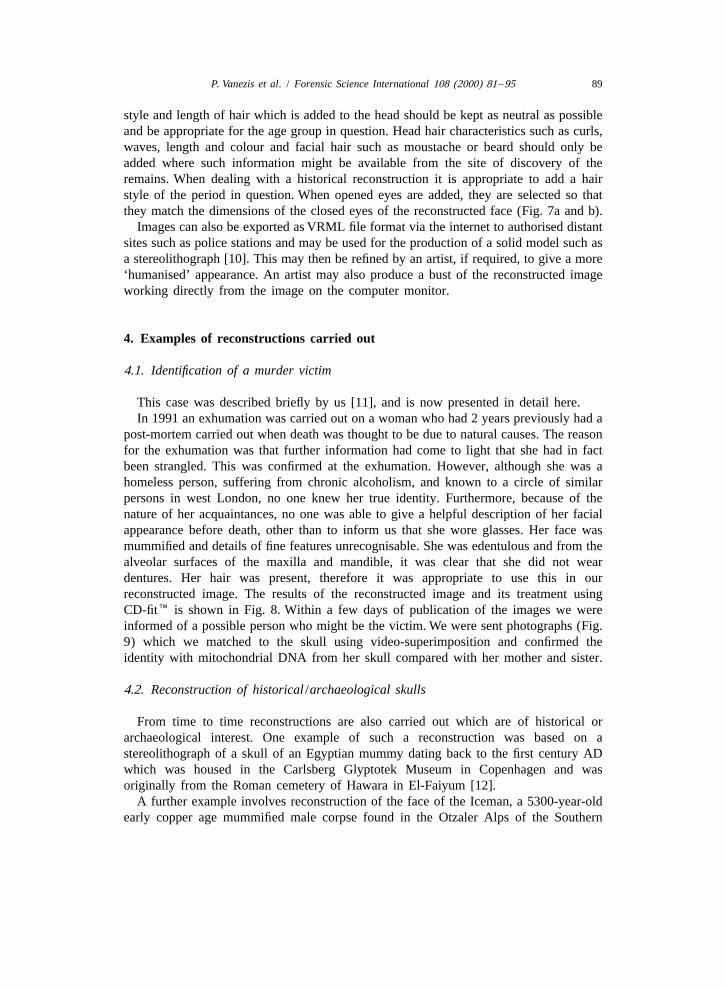
style and length of hair which is added to the head should be kept as neutral as possibleand be appropriate for the age group in question. Head hair characteristics such as curls,waves, length and colour and facial hair such as moustache or beard should only beadded where such information might be available from the site of discovery of theremains. When dealing with a historical reconstruction it is appropriate to add a hairstyle of the period in question. When opened eyes are added, they are selected so thatthey match the dimensions of the closed eyes of the reconstructed face (Fig. 7a and b).
Images can also be exported as VRML file format via the internet to authorised distantsites such as police stations and may be used for the production of a solid model such asa stereolithograph [10]. This may then be refined by an artist, if required, to give a more‘humanised’ appearance. An artist may also produce a bust of the reconstructed imageworking directly from the image on the computer monitor.
4. Examples of reconstructions carried out
4.1. Identification of a murder victim
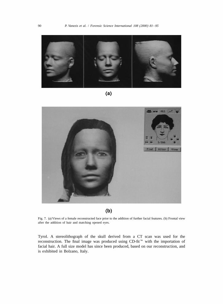
This case was described briefly by us [11], and is now presented in detail here.In 1991 an exhumation was carried out on a woman who had 2 years previously had a
post-mortem carried out when death was thought to be due to natural causes. The reasonfor the exhumation was that further information had come to light that she had in factbeen strangled. This was confirmed at the exhumation. However, although she was ahomeless person, suffering from chronic alcoholism, and known to a circle of similarpersons in west London, no one knew her true identity. Furthermore, because of thenature of her acquaintances, no one was able to give a helpful description of her facialappearance before death, other than to inform us that she wore glasses. Her face wasmummified and details of fine features unrecognisable. She was edentulous and from thealveolar surfaces of the maxilla and mandible, it was clear that she did not weardentures. Her hair was present, therefore it was appropriate to use this in ourreconstructed image. The results of the reconstructed image and its treatment usingCD-fitE is shown in Fig. 8. Within a few days of publication of the images we wereinformed of a possible person who might be the victim. We were sent photographs (Fig.9) which we matched to the skull using video-superimposition and confirmed theidentity with mitochondrial DNA from her skull compared with her mother and sister.
4.2. Reconstruction of historical /archaeological skulls
From time to time reconstructions are also carried out which are of historical orarchaeological interest. One example of such a reconstruction was based on astereolithograph of a skull of an Egyptian mummy dating back to the first century ADwhich was housed in the Carlsberg Glyptotek Museum in Copenhagen and wasoriginally from the Roman cemetery of Hawara in El-Faiyum [12].
A further example involves reconstruction of the face of the Iceman, a 5300-year-oldearly copper age mummified male corpse found in the Otzaler Alps of the Southern
90 P. Vanezis et al. / Forensic Science International 108 (2000) 81 –95
Fig. 7. (a) Views of a female reconstructed face prior to the addition of further facial features. (b) Frontal viewafter the addition of hair and matching opened eyes.
Tyrol. A stereolithograph of the skull derived from a CT scan was used for thereconstruction. The final image was produced using CD-fitE with the importation offacial hair. A full size model has since been produced, based on our reconstruction, andis exhibited in Bolzano, Italy.
P. Vanezis et al. / Forensic Science International 108 (2000) 81 –95 91
Fig. 8. Reconstructed image of murder victim.
4.3. Mass grave identifications
Computerised facial reconstruction using the earlier version of our system has beenemployed in the identification of victims murdered by the Pinochet regime in Santiago,Chile in 1973 [13]. Fourteen skulls from a mass grave containing 129 victims werereconstructed from plaster casts. The reconstructed images were successfully comparedwith photographs of suspected victims and results confirmed by superimposing skullcasts with the photographs independently by another laboratory. The author relied on theface shape, dominated by the underlying skull, to carry out the matches. No reliance wasplaced on the detail of individual facial features such as eyebrows, opened eyes, lips andears as these could not be predicted from the available information from the grave site.
5. Discussion
Three dimensional computer imaging of human anatomy for diagnostic, therapeuticand educational purposes has been in existence for a number of years with the

92 P. Vanezis et al. / Forensic Science International 108 (2000) 81 –95
Fig. 9. Photograph sent to us by family for skull-photo superimposition.
introduction of magnetic resonance imaging, computerised axial tomography and anumber of other imaging techniques. With regard to facial visualisation, this field hasbeen principally developed and successfully employed in craniofacial surgical planning[14–19].
The application of such technology for facial reconstruction from skulls for thepurpose of identification was developed in the late 1980s [20]. In essence, the principleof the technique is to ‘fit’ a three-dimensional facial image, selected from a database,over a skull image in order to produce the reconstructed face.
Other methods of computer reconstruction, such as the technique described by Tyrellet al. [21], are in the process of development. They employ Open Inventor software,developed by Silicon Graphics.
P. Vanezis et al. / Forensic Science International 108 (2000) 81 –95 93
Some promising preliminary work has been produced by another group [22] who basetheir reconstructions on the principle of deformable models. They scanned two pairs ofskulls with a CT scanner and computed three dimensional models of both skulls andtheir facial tissue. One set of skull / facial data was used as a reference and the second setto validate their method. They applied a global parametric transformation that turned thereference skull into the skull to be reconstructed. Their algorithm was based on salientlines of the skull called crest lines. Thus the crest lines of the reference skull werematched to the crest lines of the skull to be reconstructed. The algorithm was thenapplied to the reference face to obtain the reconstructed unknown face. The authorsacknowledge that their work could be greatly improved by the use of larger datasets tocover different categories of individuals and by more accurate registration of the skulland facial model.
Facial reconstruction utilising three dimensional computer graphics was an inevitabledevelopment from the manual sculpting methods with the arrival of computer technolo-gy. Yet do computerised techniques provide us with more accurate results? In ouroriginal publication [20], we demonstrated the feasibility of using this method ofreconstruction and hinted at future possibilities. Despite the clearly prototypic nature ofthe early reconstructed images, the principle behind the method of reconstructionremains a sound one.
Our present system allows more precise placement of the facial template on to theskull so that the underlying skull shape determines more accurately the facial shape ofthe reconstructed image. We are able to place skull and facial landmarks with greaterease, make adjustments where necessary and correct errors more rapidly and effectivelythan with our earlier version.
Whatever method of reconstruction is used, the central issue is whether the face is ofsufficient likeness to the original face and thus facilitates recognition. At the presenttime, the reasoning which governs the forensic investigating authority’s request for areconstruction, is simply that there is no other method of identifying the person andtherefore, despite the recognised limitations, it is worth trying. The reconstructionproduced should be employed as an aid to recognition and not be regarded, under anycircumstances, as a definitive means of identification. However, if the reconstructedimage is recognised as being that of a particular person, then positive identification canthen be achieved using comparative information such as dental records or DNAprofiling.
There are several factors that influence whether or not a reconstruction will lead to anidentification and thus be classed as a ‘success’.
• Publication of the images needs to reach those who know the deceased. Clearly,wider dissemination of the reconstructed image through the various mass media, willincrease the chances of identification.
• Relatives or others who know the deceased may, for various reasons, not wish tocome forward.
• The size of the population of missing persons is relevant to the success ofrecognition. If there are only a few missing persons in a small community, then the

94 P. Vanezis et al. / Forensic Science International 108 (2000) 81 –95
chances of success are much greater than where there is a large number of missingpersons to choose from in a large metropolis.
• Knowledge of the dead person in the community. Occasionally, someone disappears,who has no friends or relatives and consequently the community may not be awarethat he / she is missing. Furthermore, the person may have resided a long way fromthe area of discovery.
• The person may have disappeared as a child and is not found dead until later adultlife.
• The accuracy of the reconstruction. If the reconstruction is inexpertly produced, thenthis may not only diminish the chances of a recognition, but may lead to amisidentification.
Undoubtedly, the problem of assessing and improving the reliability of facialreconstructions needs to be addressed and further research carried out. It has to beconceded, however, that because of the complexity and diversity inherent in themorphology and spatial relationships of facial features, it is likely that, despite our bestefforts, the prediction of the true morphology of soft tissue features such as ears, nose,lips and eyes, will remain largely speculative — at least for the foreseeable future.
References
[1] J.P. Moss, A.D. Linney, S.R. Grindrod, C.A. Mosse, A laser scanning system for the measurement offacial surface morphology, Optics Lasers Eng. 10 (1989) 179–190.
[2] A.C. Tan, R. Richards, A.D. Linney, 3-D medical graphics — using the T800 transputer, in: Proceedingsthof the 8 OCCAM User Group Technical Meeting, 1988, pp. 83–89.
[3] J.S. Rhine, C.E. Moore, Facial reproduction tables of facial tissue thickness of American caucasoids inforensic anthropology, in: Maxwell Museum Technical Series 1, Maxwell Museum, Albuquerque, NewMexico, 1982.
[4] R.M. George, The lateral craniographic method of facial reconstruction, J. Forensic Sci. 32 (1987)1305–1330.
[5] R.M. George, Anatomical and artistic guidelines for forensic facial reconstruction, in: M.H. Iscan, R.P.Helmer (Eds.), Forensic Analysis of the Skull, Wiley-Liss, New York, 1993, pp. 215–227, Chapter 16.
[6] H. Peck, S. Peck, A concept of facial aesthetics, Angle Orthodont. 40 (1970) 284–318.[7] C.R. Goodall, Procrustes methods in the statistical analysis of shape (with discussion), J. R. Stat. Soc.
Series B 53 (1991) 285–339.[8] R.L. Hardy, Multiquadric equations of topography and other irregular surfaces, J. Geophys. Res. 76
(1971) 1906–1915.[9] K. Waters, D. Terzopoulos, Modelling and animating faces using scanned data, J. Visual. Graphics Image
Process. 24 (1991) 52–96.[10] H. Hjalgrim, N. Lynnerup, M. Liversage, A. Rosenklint, Stereolithography: potential applications in
anthropological studies, Am. J. Phys. Anthropol. 97 (1995) 329–333.[11] A.W. Sharom, P. Vanezis, R.C. Chapman, A. Gonzales, C. Blenkinsop, M.L. Rossi, Techniques in facial
identification: computer-aided facial reconstruction using a laser scanner and video superimposition, Int.J. Legal Med. 108 (1996) 194–200.
[12] N. Lynnerup, R. Neave, M. Vanezis, P. Vanezis, H. Hjalgrim, Skull reconstruction by stereolithography,thin: J.G. Clement, D.L. Thomas (Eds.), Let’s Face It! Proceedings of the 7 Scientific Meeting of the
International Association For Cranofacial Identification, Local Organising Committee of the IACI,Melbourne, 1997, pp. 11–14.

P. Vanezis et al. / Forensic Science International 108 (2000) 81 –95 95
[13] Gonzalez-Figueroa, An Evaluation of the Optical Laser Scanning System for Facial Reconstruction, Ph.D.thesis, University of Glasgow, 1998.
[14] D.C. Hemmy, D.J. David, G.T. Herman, Three-dimensional of craniofacial deformity using computedtomography, Neurosurgery 13 (1983) 534–541.
[15] M.W. Vannier, J.L. Marsh, J.O. Warren, Three dimensional CT reconstruction images for craniofacialsurgical planning and evaluation, Radiology 150 (1984) 179–184.
[16] S. Arridge, J.P. Moss, A.D. Linney, D.R. James, Three-dimensional digitisation of the face skull, J.Max.-fac. Surg. 13 (1985) 136–143.
¨[17] S.R. Arridge, Manipulation of volume data for surgical simulation, in: K.H. Hohne, H. Fuchs, S.M. Pizer(Eds.), 3D Imaging in Medicine, NATO ASI Series F 60, Springer-Verlag, Berlin, 1990, pp. 289–300.
[18] J.P. Moss, A.D. Linney, S.R. Grinrod, S.R. Arridge, J.S. Clifton, Three dimensional visualization of theface and skull using computerized tomography and laser scanning techniques, Eur. J. Orthodont. 9 (1987)247–253.
[19] J.P. Moss, A.D. Linney, S.R. Grinrod, S.R. Arridge, D. James, A computer system for the interactiveplanning and prediction of maxillo-facial surgery, Am. J. Orthodont. Dental-facial Orthopaed. 94 (1988)469–474.
[20] P. Vanezis, R.W. Blowes, A.D. Linney, A.C. Tan, R. Richards, R. Neave, Application of 3-D computergraphics for facial reconstruction and comparison with sculpting techniques, Forensic Sci. Int. 42 (1989)69–84.
[21] A.J. Tyrell, M.P. Evison, A.T. Chamberlain, M.A. Green, Forensic three-dimensional facial reconstruc-tion: historical review and contemporary developments, J. Forensic Sci. 42 (1997) 653–661.
´[22] G. Quatrehomme, S. Cotin, G. Subsol, H. Delingette, Y. Garidel, G. Grevin, M. Fidrich, P. Bailet, A.Ollier, A fully three-dimensional method for facial reconstruction based on deformable models, J.Forensic Sci. 42 (1997) 649–652.