facet test-beam experiment t501 a.k.a. cern - bba update after 2012 run
DESCRIPTION
FACET TEST-BEAM EXPERIMENT T501 a.k.a. CERN - BBA Update after 2012 run. E. Adli, University of Oslo With T501 : A. Latina, D . Schulte, G. D. Michele, J. Pfingster (CERN) In collaboration with F.J. Decker and N. Lipkowitz (SLAC ) Guest Starring at the late night show - PowerPoint PPT PresentationTRANSCRIPT
FACET TEST-BEAM EXPERIMENT T501a.k.a.
CERN-BBA
Update after 2012 run
E. Adli, University of OsloWith T501 :
A. Latina, D. Schulte, G. D. Michele, J. Pfingster (CERN)In collaboration with
F.J. Decker and N. Lipkowitz (SLAC)Guest Starring at the late night show
J.P. Delahaye (SLAC)
CLIC Project Meeting: 31 August, 2012
FACET
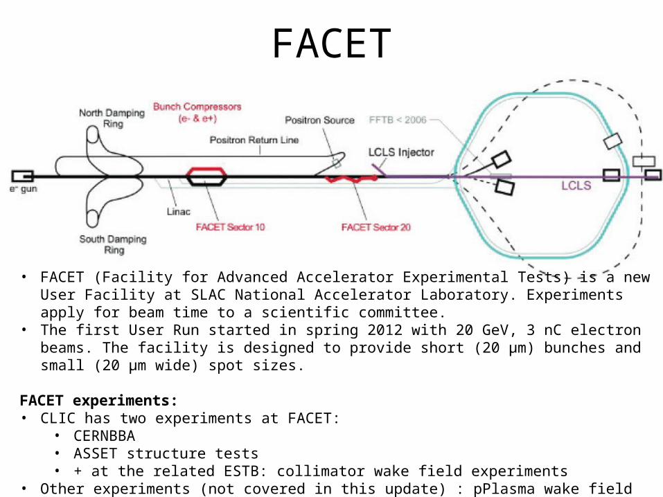
• FACET (Facility for Advanced Accelerator Experimental Tests) is a new User Facility at SLAC National Accelerator Laboratory. Experiments apply for beam time to a scientific committee.
• The first User Run started in spring 2012 with 20 GeV, 3 nC electron beams. The facility is designed to provide short (20 μm) bunches and small (20 μm wide) spot sizes.
FACET experiments:• CLIC has two experiments at FACET:
• CERNBBA• ASSET structure tests• + at the related ESTB: collimator wake field experiments
• Other experiments (not covered in this update) : pPlasma wake field acceleration, dielectric structure acceleration, Smith-Purcell radiation, magnetic switching, teraherz generation …. and more
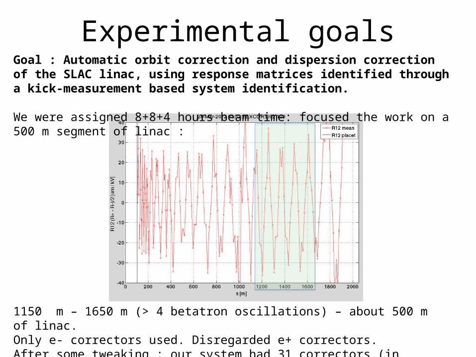
1150 m – 1650 m (> 4 betatron oscillations) – about 500 m of linac.Only e- correctors used. Disregarded e+ correctors.After some tweaking : our system had 31 correctors (in total, X and Y); 37 BPMs.
Experimental goalsGoal : Automatic orbit correction and dispersion correction of the SLAC linac, using response matrices identified through a kick-measurement based system identification.
We were assigned 8+8+4 hours beam time: focused the work on a 500 m segment of linac :
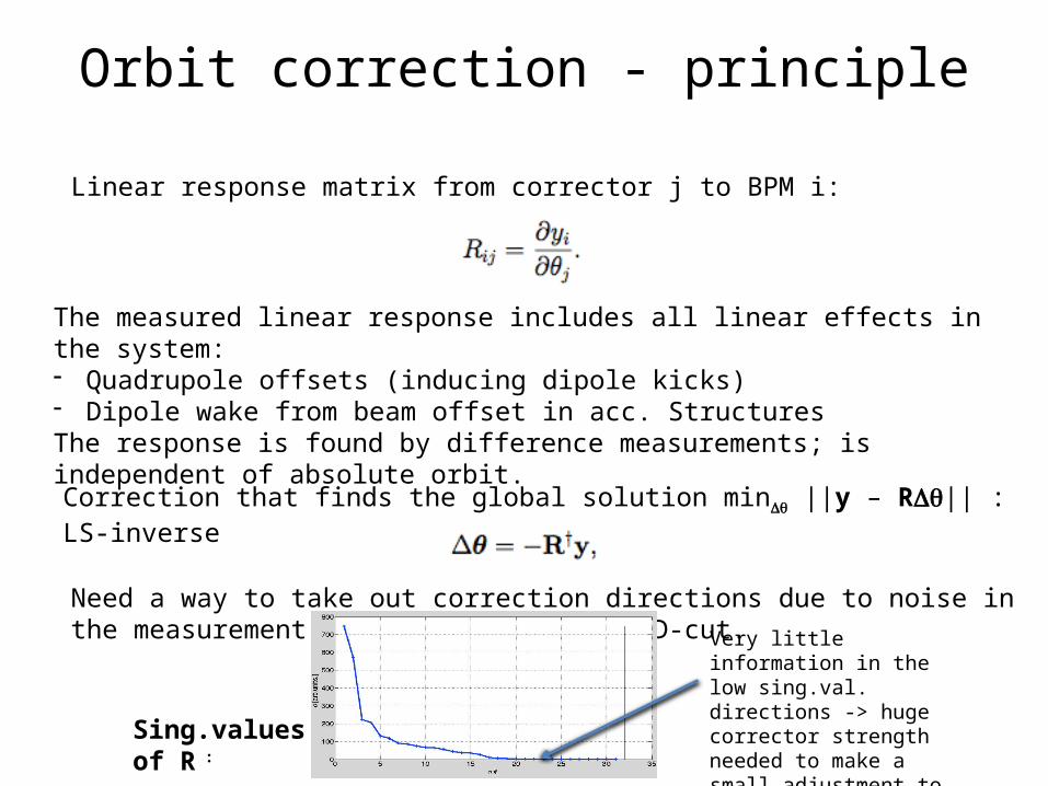
The measured linear response includes all linear effects in the system:- Quadrupole offsets (inducing dipole kicks)- Dipole wake from beam offset in acc. StructuresThe response is found by difference measurements; is independent of absolute orbit.
Linear response matrix from corrector j to BPM i:
Orbit correction - principle
Correction that finds the global solution minDq ||y – RDq|| : LS-inverse
Need a way to take out correction directions due to noise in the measurement. We use a straight SVD-cut. Very little information in the
low sing.val. directions -> huge corrector strength needed to make a small adjustment to correction -> ignore these directions.
Sing.values of R :

Response measurement
(Above) Identified Rxx response matrix for a section of the linac (17 correctors, 48 BPMs)
Rxx, Rxy, Ryx and Ryy. Some coupling is observed (some spikes can also be due to jitter during the measurement).
* Automatic response measurement procedure developed :- For each corrector do +/-, measure 100 samples (increase effective BPM res)- Iterate loop through correctors; second iteration uses amplitude of 1 mm- Result from each iteration is combined in a mathematically optimal way* Time: 2 hours for 33 correctors* Some coupling observed- Applied to the correction* Responses demonstrated to be validone shift later (24 hours later)

Orbit correction - results
2 iterations
Different example: basically we always converge to within ||X||/N ~ 10 um (here ||X|| is displayed)
Example to the top (||X||/N) after orbit correction from an arbitrary bump; induced via the response matrix.
Also feed-forward worked perfectly. Took less than one shift to reach this state, with the help of FJD and Nate. Declared success, and moved on to dispersion.
20120604_020134
20120602_015900
Each iteration: ~ 10 sec
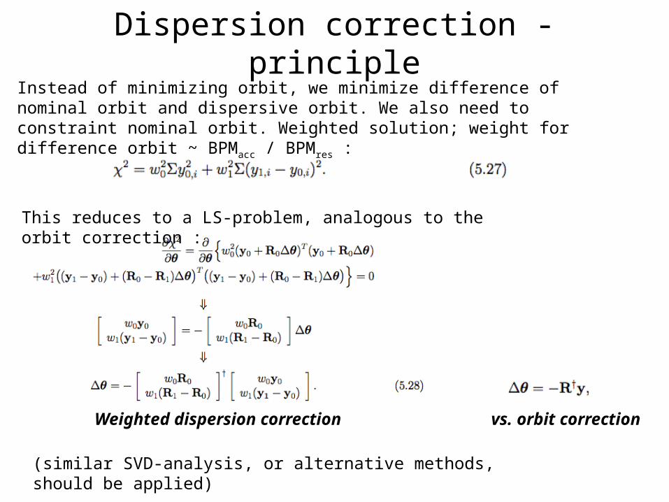
Dispersion correction - principleInstead of minimizing orbit, we minimize difference of nominal orbit and dispersive orbit. We also need to constraint nominal orbit. Weighted solution; weight for difference orbit ~ BPMacc / BPMres :
This reduces to a LS-problem, analogous to the orbit correction :
(similar SVD-analysis, or alternative methods, should be applied)
Weighted dispersion correction vs. orbit correction
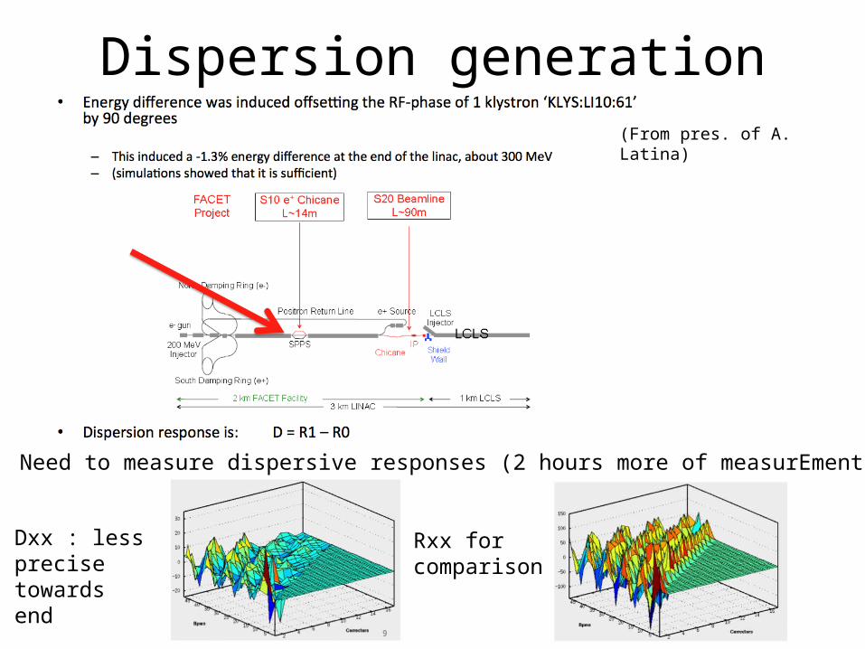
Dispersion generation(From pres. of A. Latina)
Need to measure dispersive responses (2 hours more of measurEment).
Dxx : less precise towards end
Rxx for comparison

Dispersion correction – results 1
4 iterationsWe started from the dispersion of the golden orbit (10-20 mm).
We had several results where the dispersion did not converge well.
As in this example : we start with a given dispersion, and end up with a significantly worse.
Moreover, the expected correction for next iteration is also significantly worse than what we started with.
-> was a mystery!
Each iteration: ~ 1 min

Dispersion correction – analysisA careful post-mortem of the above data showed that what happened : • drift upstream the machine changed the orbits slightly between iterations (not
unexpected)• we did not manage to go back to the better orbit we started with (unexpected) • the reason: the upstream drift induced a perturbation in the orbit that is not
correctable with our selection of correction; inside the null-space of the (total) R+
• we have 31 correctors (variables) and 148 constraints (37 BPMs x 2 x 2); large nullspace
• more correctors -> better performance
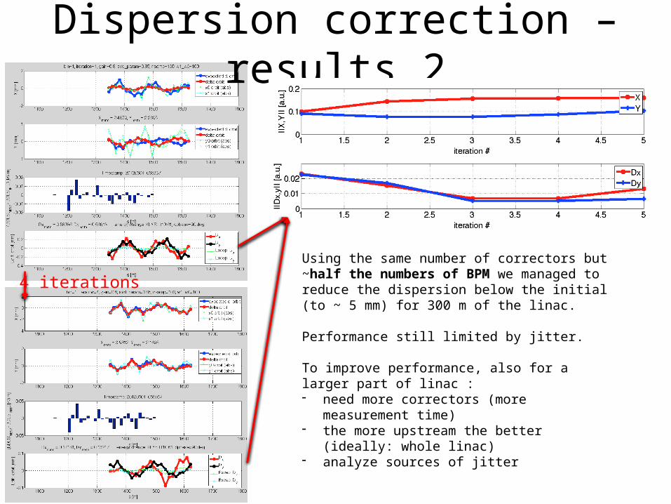
Dispersion correction – results 2
4 iterationsUsing the same number of correctors but ~half the numbers of BPM we managed to reduce the dispersion below the initial (to ~ 5 mm) for 300 m of the linac.
Performance still limited by jitter.
To improve performance, also for a larger part of linac :- need more correctors (more measurement time)- the more upstream the better (ideally: whole linac)- analyze sources of jitter

Summary• We were well received at SLAC and eventually given full freedom to
operate on the SLAC linac• Demonstrated automatic machine identification : about 3.5+3.5
minutes/corrector (nominal + dispersive) -> 4 hours for 33 correctors. Can possibly be optimized.– need factor ~4-8 more correctors for whole linac. Exactly how many to
be studies with simulations.• Demonstrated converged orbit correction on 500 m of linac from
arbitrary generated orbit bumps back to golden orbit, within ~ 10 um. Repeatable with day-old machine identification. Feed-forward to keep downstream machine in place worked perfectly.
• Demonstrated principle of dispersion correction, however, did not manage to improve the present dispersion over the whole 500 m test-section of the linac. Got improved results when reducing the number of BPMs per corrector. Ultimate performance sees limited by jitter.
• Progress of the experiment was much smoother when FACET physicists were present (FJD and Nate); not ideal to work alone during weekend owl shifts for this kind of experiment.

Future step
• Demonstrate a clear reduction in dispersion, over a larger section of the linac (> 500 m), by inducing dispersion bumps If necessary, and see a clear stable convergence
• Demonstrate a clear reduction in emittance by applying this dispersion correction
• Study new optics (weak lattice) to find a good number of correctors / BPMs and optimal performance. Study more carefully the amount of jitter and its effect.
• Requires more beam time; ideally in 12 hours blocks (larger responses).
• We plan to apply for more beam time in 2013
• We hope for the continued support and collaboration with FACET machine physicists

Updated proposal submitted to SAREC last week :
