face sheet /core disbond growth in … · face sheet/core disbond growth in honeycomb sandwich...
TRANSCRIPT
FACE SHEET/CORE DISBOND GROWTH IN HONEYCOMB SANDWICH PANELS SUBJECTED TO GROUND-AIR-GROUND PRESSURIZATION AND IN-PLANE LOADING
Zhi M. Chen
(University of California at San Diego, La Jolla, USA);
Ronald Krueger (National Institute of Aerospace, Hampton, VA, USA)
Martin Rinker (Rolls-Royce Deutschland Ltd & Co KG, Dahlewitz, Germany)
1. Introduction
Typical damage modes in light honeycomb sandwich structures include face sheet/core disbonding and core fracture, both of which can pose a threat to the structural integrity of a component. These damage modes are of particular interest to aviation certification authorities since several in-service occurrences, such as rudder structural failure and other control surface malfunctions, have been attributed to face sheet/core disbonding [1, 2]. Extensive studies have shown that face sheet/core disbonding and core fracture can lead to damage propagation caused by internal pressure changes in the core [3, 4, 5]. The increasing use of composite sandwich construction in aircraft applications makes it vitally important to understand the effect of ground-air-ground (GAG) cycles and conditions such as maneuver and gust loads on face sheet/core disbonding.
The objective of the present study was to use a fracture mechanics based approach developed earlier [3, 6] to evaluate the loading at the disbond front caused by ground-air-ground pressurization and in-plane loading. A honeycomb sandwich panel containing a circular disbond at one face sheet/core interface was modelled with three-dimensional (3D) solid finite elements. The disbond was modelled as a discrete discontinuity and the strain energy release rate along the disbond front was computed using the Virtual Crack Closure Technique (VCCT) [7, 8]. Special attention was paid to the pressure-deformation coupling which can decrease the pressure load within the disbonded sandwich section significantly when the structure is highly deformed. The
https://ntrs.nasa.gov/search.jsp?R=20160005994 2018-07-13T00:27:10+00:00Z
commercial finite element analysis software, Abaqus/Standard® [9], was used for the analyses. The recursive pressure-deformation coupling problem was solved by representing the entrapped air in the honeycomb cells as filled cavities in Abaqus/Standard®. The results show that disbond size, face sheet thickness and core thickness are important parameters that determine crack tip loading at the disbond front. Further, the pressure-deformation coupling was found to have an important load decreasing effect [6].
In this paper, a detailed problem description is provided first. Second, the analysis methodology is presented. The fracture mechanics approach used is described and the specifics of the finite element model, including the fluid-filled cavities, are introduced. Third, the initial model verification and validation are discussed. Fourth, the findings from a closely related earlier study [6] are summarized. These findings provided the basis for the current investigation. Fifth, an aircraft ascent scenario from 0 to 12192 m (0 to 40000 ft) is considered and the resulting crack tip loading at the disbond front is determined. In-plane loading to simulate maneuvers and gust conditions are also considered. Sixth, the results are shown for a curved panel, which was used to simulate potential fuselage applications. Finally, a brief summary of observations is presented and recommendations for improvement are provided.
2. Detailed Problem Description
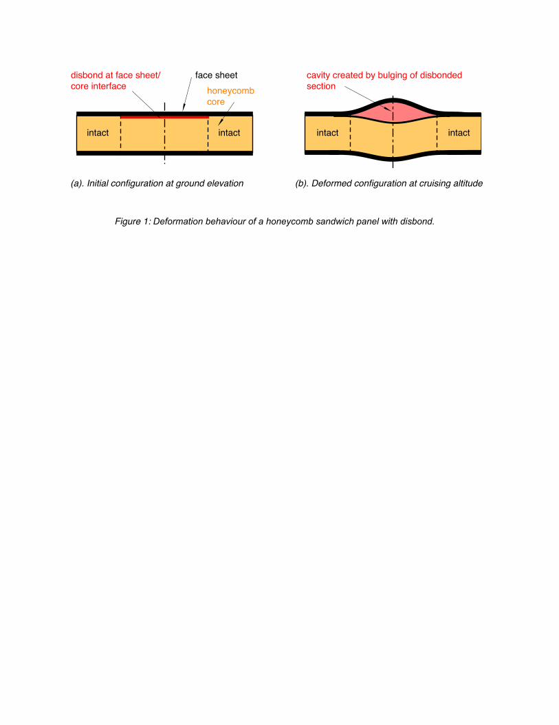
A flat sandwich panel, consisting of laminated composite face sheets and a honeycomb core with an initial circular disbond at the upper face sheet/core interface was considered, as shown in Figure 1. It is assumed that the sandwich panel is much larger than the disbonded section, which is completely surrounded by the intact part. The honeycomb core is assumed to be unvented. Air flow and rapid pressure equalization with the environment is prevented. Therefore, rapid pressure equalization inside the sandwich can only occur between the honeycomb cells in the disbonded section. Due to permeability, slow pressure equalization can also occur between the cell walls of the intact section and through the composite face sheets between the sandwich core and the environment [10, 11]. For this reason, the pressure is initially assumed equal inside and outside the sandwich and thus the sandwich structure is not loaded (and is undeformed) as shown in Figure 1(a).
When the ambient pressure decreases rapidly, for instance during the launch of a spacecraft or the ascent of an aircraft, the resulting pressure difference between the entrapped air and the ambient surrounding air causes the sandwich to expand. In the disbonded section, the thin face
FACE SHEET/CORE DISBOND GROWTH IN HONEYCOMB SANDWICH PANELS SUBJECTED TO GROUND-AIR-GROUND PRESSURIZATION AND IN-PLANE LOADING
sheets with low bending stiffness can easily be deformed by the pressure load and bulge the sandwich as shown in Figure 1(b). The out-of-plane deformation results in an increased volume, V, creating a cavity and a resulting decrease in internal pressure, p. At the same time, the decreasing ambient temperature cools the entrapped air, causing the honeycomb sandwich to shrink. This combined effect can be calculated using the ideal gas law
𝑝𝑉 = 𝑛𝑅𝑇 (1)
where T is the temperature of the gas, R = 8.314 J/(mol K) is the universal gas constant and n is the amount of substance of gas (also known as number of moles) [12]. For the face sheet/core disbond case, the amount of gas is the entrapped air inside the honeycomb cells. Bulging is considered negligible in the intact section. Hence, volume increase is only possible due to out-of-plane deformation of the core. Thus, the pressure change in the intact section is dominated mainly by the temperature change and can easily be calculated using equation (1). For the disbonded section, however, a coupled pressure-deformation problem has to be solved. Therefore, a non-linear finite element analysis was performed which coupled the ideal gas law for the air filled cavity with the deformation analysis of the sandwich. The overall goal of this work was to study the possibility of disbond growth in a partially disbonded, internally pressurized, honeycomb sandwich panel.
3. Analysis Methodology
3.1 Fracture Mechanics Approach
Two steps are required to identify, describe and address face sheet/core disbonding. First, a reliable test method to characterize the properties of the face sheet/core interface needs to be developed. Second, analysis methods are required to help assess the tendency of a structure to exhibit disbond growth. In monolithic laminates, a fracture mechanics approach is typically used, in which a critical strain energy release rate, Gc, or fracture toughness, is measured first, using simple specimens [13]. The measured fracture toughness is subsequently compared to computed values along the delamination front in a finite element model of the real structure. Propagation of the front is predicted to occur when the computed value exceeds the measured fracture toughness of the material [13]. A similar approach is proposed here, where Gc for face sheet/core disbond propagation from an existing disbond is measured using a sandwich composite specimen [14]. The Virtual Crack Closure Technique (VCCT) is used to calculate the energy
release rate along the disbond front based on the results obtained from a finite element analysis of the disbonded sandwich panel [3, 5].
3.2 Finite Element Modelling
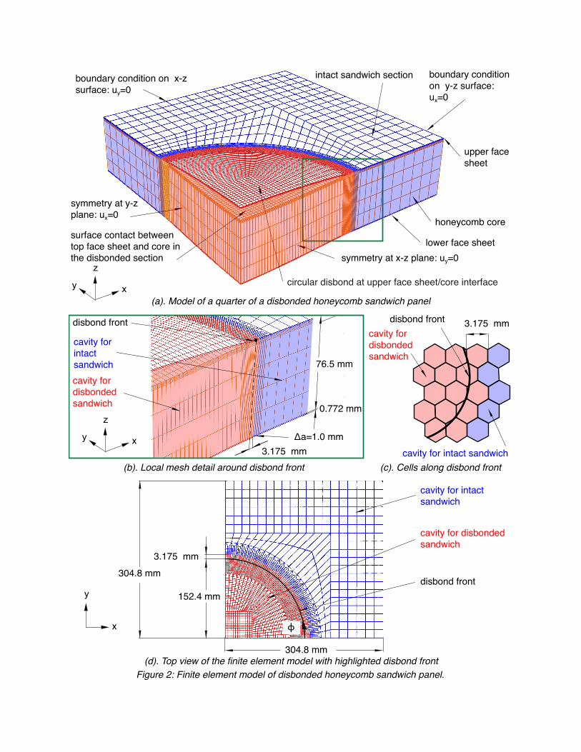
A typical 3D model of the flat panel used for the current study is shown in Figure 2. The most critical conditions identified for disbonding were chosen based on the results from an earlier study [6], which will be discussed later. Therefore, thin upper and lower face sheets (0.772 mm), thick honeycomb core (76.2 mm), and a large, circular disbond radius (152.4 mm) were selected for the current model. The total panel length and width were four times as large as the radius [6]. Due to the symmetry of the problem, a simple model of a quarter was used for most analyses to reduce computational time. The validity of this assumption was verified by comparing results obtained from the model of a quarter with those obtained from full models where the entire disbonded area and surrounding intact area had been included in the model, as will be discussed later. A fine mesh was used for the circular disbonded part since this area and the vicinity of the crack front were the main focus of this study. An element length of Δa=1.0 mm was used for the elements at the disbond front, as shown in the detail of Figure 2(b). A coarser mesh was used to model the intact part of the square model. Surface based contact was used to prevent the penetration of the disbonded sandwich parts.
For all analyses, the commercial finite element software Abaqus/Standard® was used [9]. Quadratic brick elements with 20 nodes (C3D20) were used to model the face sheets and the honeycomb core [9]. In accordance with the earlier study [6], it was assumed that both face sheets were made of CYCOM 5320PW plain weave fabric with a [45/0/90/-45] stacking sequence (quasi-isotropic layup). The material properties of the individual ply are listed in Table 1 and were based on the material qualification performed by the National Center for Advanced Materials Performance (NCAMP) [15]. The face sheets were modelled with one solid brick element through the thickness. A composite layered section was defined within each element and a different material orientation was assigned for each ply through the thickness [9]. Furthermore, it was assumed that the sandwich core was made of Hexcel HRH-10® honeycomb consisting of NOMEX® paper with 48 kg/m3 (3.0 lb/ft3) core density and 3.175 mm (1/8”) cell size [16]. The honeycomb material properties are listed in Table 1. To keep the model simple, the honeycomb cell structure was not explicitly modelled; rather, the core was assumed to be a homogeneous, orthotropic material. The core was modelled with seven
FACE SHEET/CORE DISBOND GROWTH IN HONEYCOMB SANDWICH PANELS SUBJECTED TO GROUND-AIR-GROUND PRESSURIZATION AND IN-PLANE LOADING
elements through the thickness as shown in Figure 2, using a finer mesh near the delaminated interface.
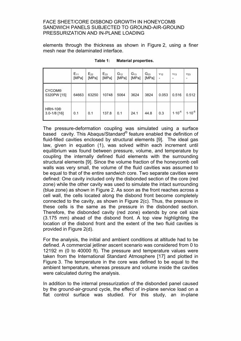
Table 1: Material properties.
E11 [MPa]
E22 [MPa]
E33 [MPa]
G12 [MPa]
G13 [MPa]
G23 [MPa]
ν12 -
ν13 -
ν23 -
CYCOM® 5320PW [15] 64663 63250 10748 5064 3624 3824 0.053 0.516 0.512
HRH-10® 3.0-1/8 [16] 0.1 0.1 137.8 0.1 24.1 44.8 0.3 1⋅10-6 1⋅10-6
The pressure-deformation coupling was simulated using a surface based cavity. This Abaqus/Standard® feature enabled the definition of fluid-filled cavities enclosed by structural elements [9]. The ideal gas law, given in equation (1), was solved within each increment until equilibrium was found between pressure, volume, and temperature by coupling the internally defined fluid elements with the surrounding structural elements [9]. Since the volume fraction of the honeycomb cell walls was very small, the volume of the fluid cavities was assumed to be equal to that of the entire sandwich core. Two separate cavities were defined: One cavity included only the disbonded section of the core (red zone) while the other cavity was used to simulate the intact surrounding (blue zone) as shown in Figure 2. As soon as the front reaches across a cell wall, the cells located along the disbond front become completely connected to the cavity, as shown in Figure 2(c). Thus, the pressure in these cells is the same as the pressure in the disbonded section. Therefore, the disbonded cavity (red zone) extends by one cell size (3.175 mm) ahead of the disbond front. A top view highlighting the location of the disbond front and the extent of the two fluid cavities is provided in Figure 2(d).
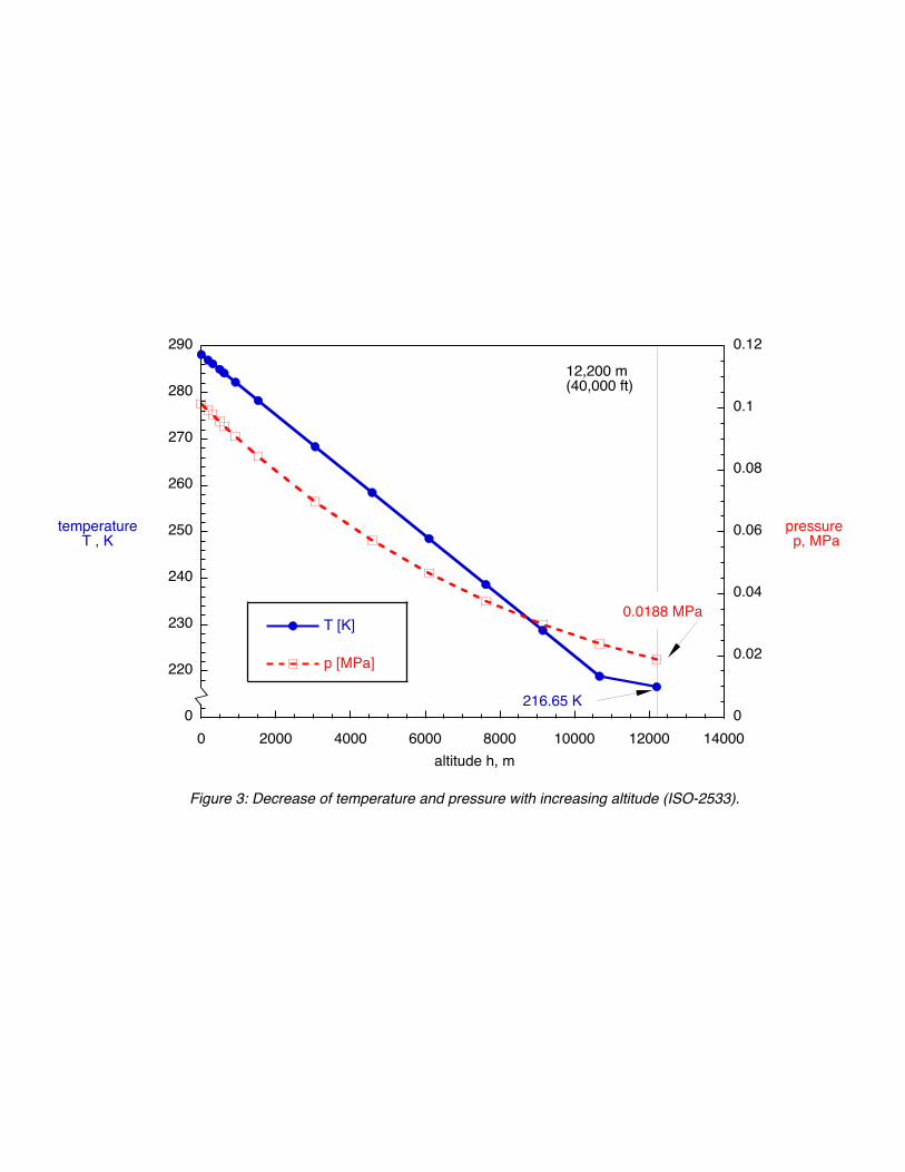
For the analysis, the initial and ambient conditions at altitude had to be defined. A commercial jetliner ascent scenario was considered from 0 to 12192 m (0 to 40000 ft). The pressure and temperature values were taken from the International Standard Atmosphere [17] and plotted in Figure 3. The temperature in the core was defined to be equal to the ambient temperature, whereas pressure and volume inside the cavities were calculated during the analysis.
In addition to the internal pressurization of the disbonded panel caused by the ground-air-ground cycle, the effect of in-plane service load on a flat control surface was studied. For this study, an in-plane
displacement was applied on the right face of the model as shown in Figure 4 to simulate a 0.2% strain condition. A compressive strain condition was chosen since it was believed that it would aggravate the condition along the crack front and thus increase the possibility of disbond growth.
Furthermore, the effect of the ground-air-ground pressurization was studied for a curved honeycomb sandwich panel with a constant radius, as opposed to a flat panel. The motivation was that honeycomb sandwich constructions may be used for cylindrical fuselage structures. A 3000 mm radius was chosen for this study, as shown for the model in Figure 5.
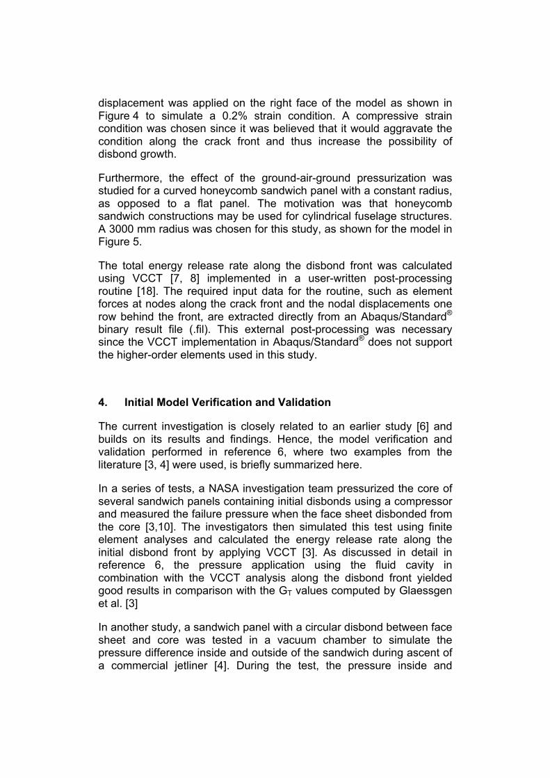
The total energy release rate along the disbond front was calculated using VCCT [7, 8] implemented in a user-written post-processing routine [18]. The required input data for the routine, such as element forces at nodes along the crack front and the nodal displacements one row behind the front, are extracted directly from an Abaqus/Standard® binary result file (.fil). This external post-processing was necessary since the VCCT implementation in Abaqus/Standard® does not support the higher-order elements used in this study.
4. Initial Model Verification and Validation
The current investigation is closely related to an earlier study [6] and builds on its results and findings. Hence, the model verification and validation performed in reference 6, where two examples from the literature [3, 4] were used, is briefly summarized here.
In a series of tests, a NASA investigation team pressurized the core of several sandwich panels containing initial disbonds using a compressor and measured the failure pressure when the face sheet disbonded from the core [3,10]. The investigators then simulated this test using finite element analyses and calculated the energy release rate along the initial disbond front by applying VCCT [3]. As discussed in detail in reference 6, the pressure application using the fluid cavity in combination with the VCCT analysis along the disbond front yielded good results in comparison with the GT values computed by Glaessgen et al. [3]
In another study, a sandwich panel with a circular disbond between face sheet and core was tested in a vacuum chamber to simulate the pressure difference inside and outside of the sandwich during ascent of a commercial jetliner [4]. During the test, the pressure inside and
FACE SHEET/CORE DISBOND GROWTH IN HONEYCOMB SANDWICH PANELS SUBJECTED TO GROUND-AIR-GROUND PRESSURIZATION AND IN-PLANE LOADING
outside of the sandwich was measured. To validate the current modelling technique and the solution of the pressure-deformation coupling problem by using the Abaqus/Standard® fluid cavity feature, the test was reanalysed. Using the modelling approach introduced in section 3, the pressure in the disbonded section was calculated. As discussed in detail in reference 6, the results were within 2% of the measured pressure and within about 1 % of the analysis results presented by Hilgers [4]. The good agreement confirmed that the suggested modelling technique is suitable for the analyses of internally pressurized honeycomb sandwich structures. Additional validation of the modelling approach, however, should also include a comparison of the local deformation field of the disbonded face sheet.
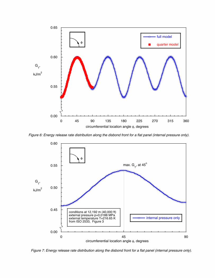
In the current study, models of a quarter of the panels, as shown in Figures 2, 4 and 5, were used for most of the analyses to reduce computational time. The validity of this assumption was confirmed by comparing results obtained from the model of a quarter with those obtained from a full model (not shown) where the entire disbonded area and intact area had been included in the model. The computed total energy release rate, GT, along the disbond front was plotted as a function of the circumferential location angle, Φ, as shown in Figure 6. `The energy release rate varies along the disbond front and reaches peak values at Φ=45°, 135°, 225° and 315°, local minima at Φ=90° and 270°, and absolute minima at Φ=0° (360°) and 180° (blue open circles and solid line). The results obtained from the model of a quarter (solid red squares) are in excellent agreement with the results from the full model. Thus, for the current configuration of a sandwich with a quasi-isotropic layup of the face sheets and an orthotropic core, the model of a quarter may be used. Computed results (not shown) for other face sheet layups, however, indicated that the symmetry is lost, although the panel and disbond geometry, as well as the loads, are still symmetric.
5. Analysis Results
The current investigation is closely related to an earlier study [6] and builds on its results and findings. Hence, a summary of the findings is provided here. During that study, a series of analyses were performed to investigate the influence of the disbond radius, the face sheet thickness, the core thickness and the core density on the crack tip loading along the disbond front.
The sandwich configuration with the largest disbond radius and the thinnest face sheets was identified as the most critical case. For this case, significant bulging occurs and the crack opening results in a
higher energy release rate along the front (higher crack tip loading). The core thickness was identified as a third important parameter. The pressure load, and consequently the crack front loading, are higher in sandwich configurations with thick cores. For the case investigated, the core density, however, did not affect the global deformation behaviour of the sandwich panel. Based on these results, the dimensions of the current configuration (shown in Figure 2) with thin face sheets (0.772 mm), thick core (76.2 mm), and large, circular disbond radius (152.4 mm) were chosen. Under this condition, the highest amount of air particles were trapped inside the disbond cavity. The large disbonded section and thin face sheet results in a low flexural rigidity which can cause significant bulging due to the internal pressurization. Thus, the disbond front would also experience the highest crack tip loading.
5.1 Analysis of a Flat Panel Under Internal Pressure, In-Plane and Combined Loading
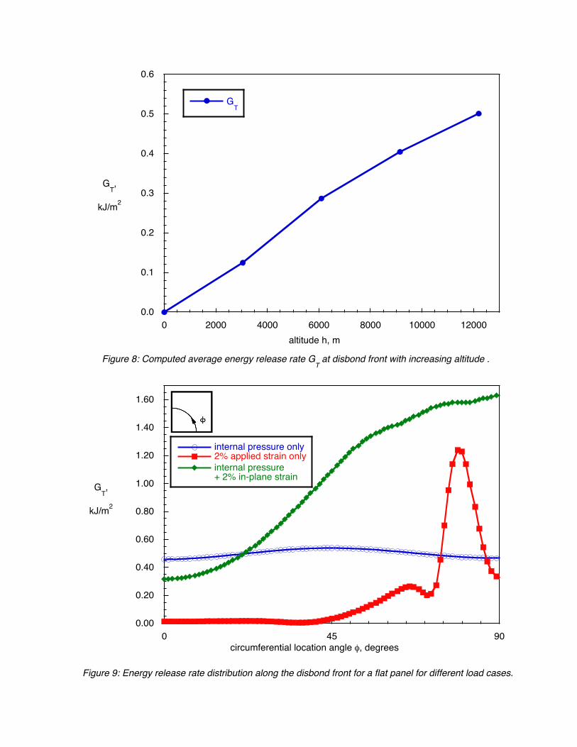
First, a load case was studied where the panel was only subjected to the conditions (pressure and temperature) at an altitude of 12192 m (40000 ft.). This analysis used the model shown in Figure 2. The computed total energy release rate, GT, along the disbond front was plotted as a function of the circumferential location angle, Φ, as shown in Figure 7. As discussed before (Figure 6), GT varies along the disbond front with minima at Φ=0° and Φ=90° and a peak value at Φ=45°. To study the effect of altitude, the averaged GT values along the entire front were computed for conditions at different altitudes. As mentioned earlier, both the ambient temperature and pressure decrease as the altitude increases from ground level to flight level (Figure 5). These changing ambient conditions affect the volume of the entrapped air in the honeycomb cells according to the ideal gas law. The decreasing ambient pressure creates a pressure difference between the entrapped air and the ambient air, causing the honeycomb sandwich to expand to equilibrate the difference. Simultaneously, the internal temperature drops due to the decrease in the ambient temperature, causing the air pocket to shrink. As a consequence, the computed GT values increased almost linearly, as shown in Figure 8. This indicated that there is an overall tendency for the entrapped air volume to expand with increasing altitude. The most critical case is at the cruising altitude of 12192 m (40000 ft.) where an aircraft would remain for most of the duration of the flight.
Second, a load case was studied where the panel was subjected only to an in-plane displacement to simulate a 0.2% compression strain, which might be induced by the service loads on a flat control surface. A
FACE SHEET/CORE DISBOND GROWTH IN HONEYCOMB SANDWICH PANELS SUBJECTED TO GROUND-AIR-GROUND PRESSURIZATION AND IN-PLANE LOADING
compressive strain condition was chosen since it was believed that it would aggravate the condition along the crack front and thus increase the possibility of disbond growth. For this analysis, the model and boundary conditions shown in Figure 4 were used. Under compression, the out-of-plane deformations observed for the disbonded zone differed from those seen for the pure pressure case shown in Figure 2a. Local contact was observed as shown in Figure 4. This contact behaviour is reflected in the distribution of the computed total energy release rate, GT, along the disbond front. In Figure 9, the distribution from the in-plane load case (solid red squares and solid red line) is compared to the result from the pressure-only load case discussed previously (open blue circles and solid blue line). Along the front where local contact was observed, GT is practically zero. An increase in GT occurs where the disbond opens (Φ=50-90°) and GT peaks where a large out-of-plane deformation is observed locally.
Third, a load case was studied combining the two load cases (pressure only and in-plane load only) where the panel was simultaneously subjected to the conditions (pressure and temperature) at an altitude of 12192 m (40000 ft.) and the in-plane displacement to simulate a 0.2% compression strain. The computed total energy release rate, GT, along the disbond front was added to the plot in Figure 9 (solid green diamonds and solid green line). As expected, the presence of the in-plane compressive strain aggravates the condition along the crack front and the GT values are significantly higher compared to the results from the pressure only case. Due to the non-linearity of the problem, the results for the combined load case cannot simply be obtained by superposition of the individual load cases.
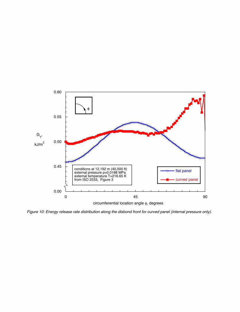
5.2 Analysis of a Curved Panel Under Internal Pressure Loading
Additionally, the effect of the ground-air-ground pressurization was studied for a curved honeycomb sandwich panel, as opposed to a flat panel. The motivation was that honeycomb sandwich constructions may be used for fuselage structures. A 3000 mm radius was chosen for this study, as shown for the model in Figure 5. In Figure 10, the distribution of the energy release rate obtained from the pressure only load case for the flat panel (open blue circles and solid blue line) is compared to the result for the same load case but obtained for the curved panel (solid red squares and solid red line). The results obtained for the cylindrical panel are slightly higher for Φ=0o. There is little variation of GT along a significant section of the disbond front (0o≤Φ≤60o). For Φ>60o GT increases until the Φ=90o location, where the strain energy spikes. The local deformation that causes this spike needs to be investigated
further. On average, however, the computed GT for this curved panel was higher compared to the results obtained from the analysis of the flat panel. This initial observation is somewhat unexpected since, prior to the analyses, it was believed that the curvature would alleviate the condition along the crack front and thus decrease the possibility of disbond growth. Additional analyses with different radii are required before a definite statement about the effect of panel curvature on the crack tip loading can be made.
6. Summary and Concluding Remarks
A study of a sandwich panel containing a circular disbond at the face sheet/core interface was presented. A fracture mechanics approach was used to evaluate the crack tip loading at the disbond front. For the current study, the strain energy release rate was computed using the Virtual Crack Closure Technique. Special attention was paid to the pressure-deformation coupling within the disbonded sandwich section, which was accomplished by using a finite element model that included special fluid-filled cavities to model the entrapped air. An initial model verification and validation performed in reference 6 showed that computed energy release rates along the front, and pressure values inside the disbond were in good agreement with published values obtained from the open literature. Findings from reference 6 provided the basis of the current investigation and led to the decision to model a sandwich panel with a large disbond, thin face sheet, and thick core which had been shown to be the critical configuration for disbond growth.
Pressure and temperature changes were based on an aircraft ascent scenario from 0 to 12192 m (0 to 40000 ft) and the resulting crack tip loading at the disbond front was determined. The effects of maneuvers and gust conditions were simulated by modelling in-plane loading. Additionally, potential applications for the aircraft fuselage were studied by modelling panels with curvature. The following observations were made:
• The computed averaged energy release rate values increased almost linearly with increasing altitude. Thus, the cruising altitude of 12192 m (40000 ft.) where an aircraft would remain for most of the duration of the flight, was identified as the most critical case.
• As expected, the presence of the in-plane compressive strain aggravated the condition along the crack front and the computed energy release rate values were significantly higher than the results from the pressure-only case.
FACE SHEET/CORE DISBOND GROWTH IN HONEYCOMB SANDWICH PANELS SUBJECTED TO GROUND-AIR-GROUND PRESSURIZATION AND IN-PLANE LOADING
• Due to the non-linearity of the analyses, the results for combined load cases cannot simply be obtained by superposition of the individual load cases.
• Computed energy release rate values along the disbond front in a curved panel with 3000 mm radius were locally, and on average, higher than the values computed for a flat panel subjected to the same conditions. This initial observation was somewhat unexpected since, prior to the analyses, it was believed that the curvature would alleviate the condition along the crack front and thus decrease the possibility of disbond growth.
Overall, the finite element analysis with fluid cavities performs well and is capable of capturing the pressure-deformation coupling in the disbonded section of the panel. Based on the current preliminary results, however, it is recommended that additional validation studies be performed. These studies should include a comparison of the computed local deformation field of the disbonded face sheet with far field measurements and a comparison of the computed pressure inside the cavity with measured values. Additionally, analyses of curved panels with different radii should be performed before a definite statement about the effect of panel curvature on the crack tip loading is made.
7. Acknowledgements
The analyses were performed at the Durability, Damage Tolerance and Reliability Branch at NASA Langley Research Center, Hampton, Virginia, USA while Zhi Chen was a participant in the Langley Aerospace Research Student Scholars (LARSS) program. Ronald Krueger was supported under contract NNL09AA00A and Martin Rinker was a visiting scientist at the National Institute of Aerospace (NIA).
8. References
[1] Air Accident Investigation Branch (1992). AAIB Bulletin 8/92 Ref: EW/A92/5/1: Air Accident Investigation, UK.
[2] Transportation Safety Board of Canada (2007). Aviation Investigation Report A05F0047: Minister of Public Works and Government Services Canada, 2007.
[3] Glaessgen, E.H., Reeder J.R., Sleight D.W., Wang J.T., Raju I.S. and Harris C.E. (2005). Debonding Failure of Sandwich-Composite Cryogenic Fuel Tank with Internal Core Pressure: J. Spacecraft and Rockets, vol. 42, no. 4, pp. 613-627.
[4] Hilgers, R. (2009). Substantiation of Damage Growth within Sandwich Structures: FAA Workshop for Composite Damage Tolerance & Maintenance, Tokyo, Japan.
[5] Goyal, V., Tuck-Lee, J.P., Rome, J., and Lundgren, E. (2014). Failure Analysis of Unvented Honeycomb Structures: 29th ASC Technical Conference, University of California at San Diego, La Jolla, CA.
[6] Rinker, M., Krueger, R, and Ratcliffe, J. (2013). Analysis of an Aircraft Honeycomb Sandwich Panel with Circular Facesheet/Core Disbond Subjected to Ground-Air Pressurization: NASA/CR-2013-217974.
[7] Rybicki, E.F. and Kanninen, M.F. (1977). A Finite Element Calculation of Stress Intensity Factors by a Modified Crack Closure Integral: Engineering Fracture Mechanics, vol. 9, no. 4, pp. 931-938.
[8] Krueger, R. (2004). Virtual Crack Closure Technique: History, Approach, and Applications: Applied Mechanics Reviews, vol. 57, no. 2, pp. 109-143.
[9] Abaqus/Standard® 6.12 Documentation (2012). Dassault Systemes Simulia Corporation, Providence, RI, USA.
[10] Goetz et al. (2000). Final Report of the X-33 Liquid Hydrogen Tank Test Investigation Team: National Aeronautics and Space Administration, Huntsville, AL, USA.
[11] Glass, D.E., Raman, V.V., Venkat, V.S. and Sankaran, S.N. (1999). Graphite/Epoxy Honeycomb Core Sandwich Permeability Under Mechanical Loads: Composite Structures, vol. 44, no. 4, pp. 253-261.
[12] Moran, J.M. and Shapiro, H.N. (2000). Fundamentals of Engineering Thermodynamics: Wiley, 4th Edition.
[13] Raju, I.S. and O'Brien, T.K. (2008). Fracture mechanics concepts, stress fields, strain energy release rates, delamination and growth
FACE SHEET/CORE DISBOND GROWTH IN HONEYCOMB SANDWICH PANELS SUBJECTED TO GROUND-AIR-GROUND PRESSURIZATION AND IN-PLANE LOADING
criteria: Delamination behaviour of composites, S. Sridharan, Ed.: Woodhead Publishing in Materials.
[14] Rinker, M., Ratcliffe, J.G., Adams, D., and Krueger, R. (2013). Characterizing Face sheet/Core Disbonding in Honeycomb Core Sandwich Structure: NASA/CR-2013-217959.
[15] National Center for Advanced Materials Performance (NCAMP), www.niar.wichita.edu/coe/ncamp.
[16] HexWebTM Honeycomb Attributes and Properties. Material Data Sheet, Hexcel Composites, 1999.
[17] ISO 2533 (1975). Standard Atmosphere: International Organization for Standardization.
[18] Krueger, R. and Goetze, D. (2006). Influence of Finite Element Software on Energy Release Rates Computed Using the Virtual Crack Closure Technique: NASA/CR-2006-214523.
cavity created by bulging of disbonded section
disbond at face sheet/core interface
(a). Initial configuration at ground elevation (b). Deformed configuration at cruising altitude
face sheethoneycomb core
intact intactintact intact
Figure 1: Deformation behaviour of a honeycomb sandwich panel with disbond.
circular disbond at upper face sheet/core interface
(a). Model of a quarter of a disbonded honeycomb sandwich panel
(b). Local mesh detail around disbond front
intact sandwich section
symmetry at y-z plane: ux=0
symmetry at x-z plane: uy=0lower face sheet
upper face sheet
honeycomb core
(d). Top view of the finite element model with highlighted disbond front
304.8 mm
304.8 mm
152.4 mmdisbond front
cavity for intact sandwich
cavity for disbonded sandwich
xy
z
x
y
cavity for intact sandwichcavity for disbonded sandwich
disbond front
xy
z
3.175 mm
ϕ
Figure 2: Finite element model of disbonded honeycomb sandwich panel.
boundary condition on y-z surface: ux=0
boundary condition on x-z surface: uy=0
surface contact between top face sheet and core in the disbonded section
0.772 mm
Δa=1.0 mm
76.5 mm
3.175 mm
(c). Cells along disbond front
disbond front 3.175 mm
cavity for intact sandwich
cavity for disbondedsandwich
0
220
230
240
250
260
270
280
290
0
0.02
0.04
0.06
0.08
0.1
0.12
0 2000 4000 6000 8000 10000 12000 14000
T [K]
p [MPa]
temperatureT , K
pressure p, MPa
altitude h, m
12,200 m(40,000 ft)
0.0188 MPa
216.65 K
Figure 3: Decrease of temperature and pressure with increasing altitude (ISO-2533).
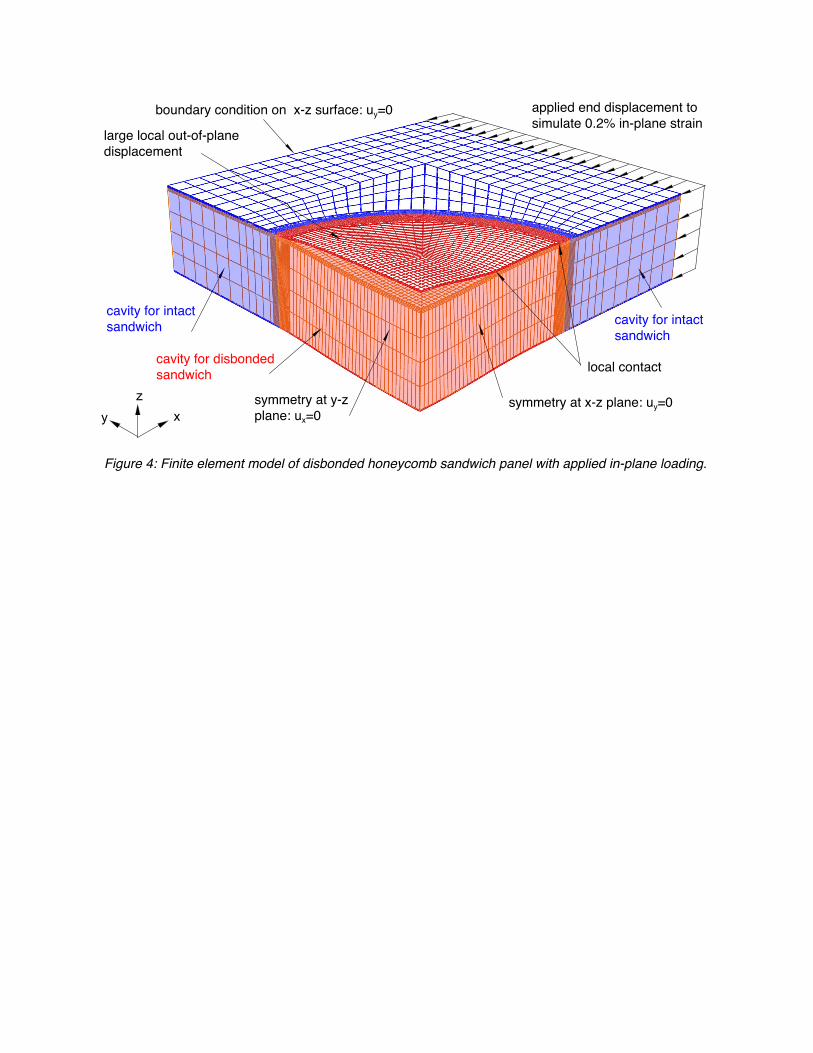
Figure 4: Finite element model of disbonded honeycomb sandwich panel with applied in-plane loading.
cavity for intact sandwich
cavity for intactsandwich
xyz
applied end displacement to simulate 0.2% in-plane strain
symmetry at y-z plane: ux=0
symmetry at x-z plane: uy=0
cavity for disbonded sandwich local contact
large local out-of-plane displacement
boundary condition on x-z surface: uy=0
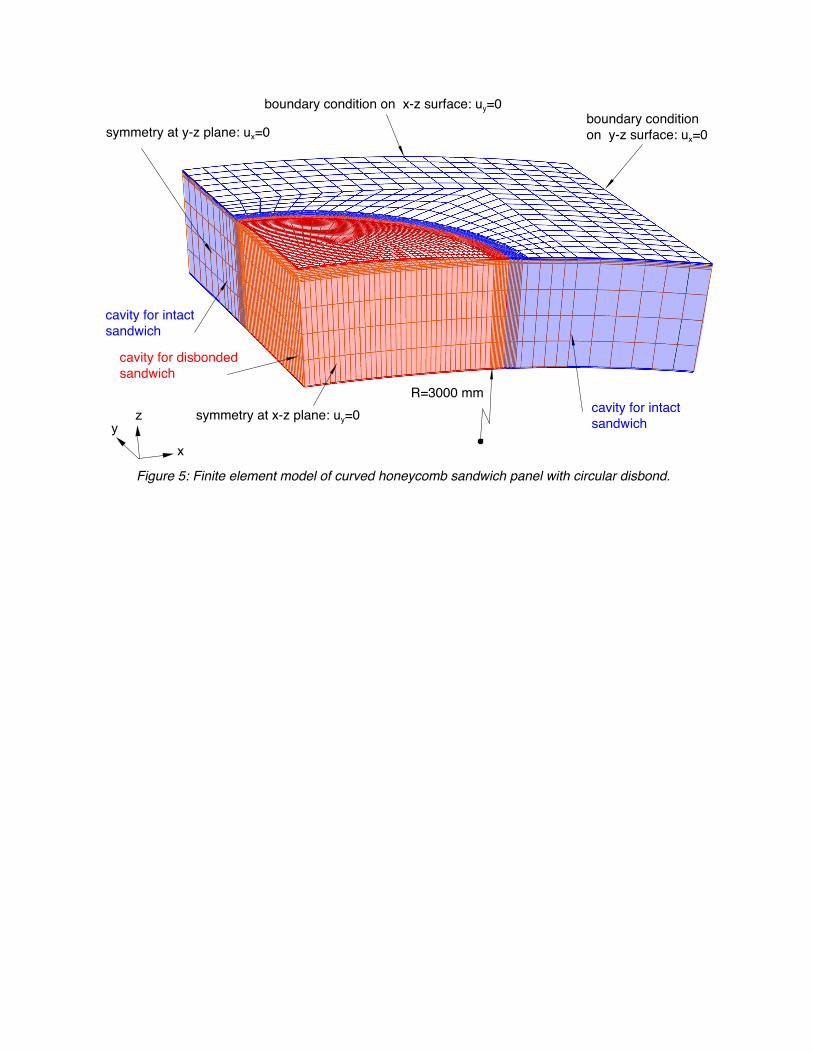
Figure 5: Finite element model of curved honeycomb sandwich panel with circular disbond.
cavity for intact sandwich
x
yz
cavity for intactsandwich
cavity for disbonded sandwich
R=3000 mm
boundary condition on x-z surface: uy=0boundary condition on y-z surface: ux=0symmetry at y-z plane: ux=0
symmetry at x-z plane: uy=0
0.00
0.45
0.50
0.55
0.60
0 45 90
internal pressure only
GT,
kJ/m2
circumferential location angle φ, degrees
Figure 7: Energy release rate distribution along the disbond front for a flat panel (internal pressure only).
conditions at 12,192 m (40,000 ft)external pressure p=0.0188 MPaexternal temperature T=216.65 Kfrom ISO 2533, Figure 3
max. GT, at 45o
0.00
0.55
0.60
0.65
0 45 90 135 180 225 270 315 360
full model
quarter model
GT,
kJ/m2
circumferential location angle φ, degrees
Figure 6: Energy release rate distribution along the disbond front for a flat panel (internal pressure only).
0.00
0.20
0.40
0.60
0.80
1.00
1.20
1.40
1.60
0 45 90
internal pressure only
internal pressure + 2% in-plane strain
2% applied strain only
GT,
kJ/m2
circumferential location angle φ, degrees
Figure 9: Energy release rate distribution along the disbond front for a flat panel for different load cases.
0.0
0.1
0.2
0.3
0.4
0.5
0.6
0 2000 4000 6000 8000 10000 12000
GT
GT,
kJ/m2
altitude h, m
Figure 8: Computed average energy release rate GT at disbond front with increasing altitude .
0.00
0.45
0.50
0.55
0.60
0 45 90
flat panel
curved panel
GT,
kJ/m2
circumferential location angle φ, degrees
Figure 10: Energy release rate distribution along the disbond front for curved panel (internal pressure only).
conditions at 12,192 m (40,000 ft)external pressure p=0.0188 MPaexternal temperature T=216.65 Kfrom ISO 2533, Figure 3