fabrication of fe3o4/sio2 core–shell nanoparticle monolayer as catalyst for carbon nanotube growth...
TRANSCRIPT

Thin Solid Films 537 (2013) 252–255
Contents lists available at SciVerse ScienceDirect
Thin Solid Films
j ourna l homepage: www.e lsev ie r .com/ locate / ts f
Fabrication of Fe3O4/SiO2 core–shell nanoparticle monolayer as catalyst for carbonnanotube growth using Langmuir–Blodgett technique
Masahito Kushida ⁎, Tetsuya Koide, Ippei Osada, Yoshiaki Imaizumi, Kouhei Kawasaki, Takehiro SugawaraGraduate School of Engineering, Chiba University, Chiba 263-8522, Japan
⁎ Corresponding author. Tel./fax: +81 43 290 3438.E-mail address: [email protected] (M. Kush
0040-6090/$ – see front matter © 2013 Elsevier B.V. Allhttp://dx.doi.org/10.1016/j.tsf.2013.04.031
a b s t r a c t
a r t i c l e i n f oArticle history:Received 5 June 2012Received in revised form 9 April 2013Accepted 10 April 2013Available online 24 April 2013
Keywords:Catalytic nanoparticlesCore–shellLangmuir–Blodgett filmsCarbon nanotube growthMolecular electronic devices
In this work, an approach of controllable distance of catalytic nanoparticles (NPs) shrouded in shell layer forcarbon nanotube (CNT) growth has been developed with the aid of the Langmuir–Blodgett (LB) technique. Co-agulation of core–shell NPs was controlled by the surface pressure of the LB technique. Scanning electronmicro-scope images show that core–shell NP LB filmwithout coagulation and vacancies was observed. The approach ofcore–shell NP LB film revealed in this work could potentially be applied in catalytic NPmonolayer formation andhigh activity of catalytic NPs for CNT growth.
© 2013 Elsevier B.V. All rights reserved.
1. Introduction
Langmuir–Blodgett (LB) technique [1] is an important method forpreparing oriented and multilayered ultrathin films for the formation[2–4] of molecular electronic devices. Hino et al. [5,6] reported thatpolyimide LB films sandwiched between Au and Al electrode were elec-tric transfer devices. LB filmswere prepared from amphiphilic moleculesas a popular brief. Hydrophilic groups of the molecules faced water sur-face and hydrophobic groupswere oriented to air. Themolecules formeda monolayer in air–water interface. LB films were not prepared from hy-drophobic molecules like an n-octadecane, but were prepared from hy-drophobic molecules mixed with amphiphilic molecules like a arachidicacid [7]. LB filmswere not prepared fromhydrophilic molecules, becausehydrophilic molecules blended in with subphase (water) of frequent in-gredient in LB techniques. LB films were prepared from materials withspecific gravity greater than water without ease. Imaizumi et al. [8,9]reported that giant carbon nanotube construction were synthesized bychemical vapor deposition techniques using iron (III) stearate as catalyst.
In general, catalytic metal nanoparticles (NPs) for carbon nanotube(CNT) growthwere formed on a substrate under two time frames as fol-lows. First, Fe of 1 or 2 nm thick film was deposited on a substrate byvacuum evaporation [10], or sputter techniques [11]. Second, the sub-strate was heated from 500 to 600 °C in a vacuum, after that, Fe of 1or 2 thick film was agglutinated, and then Fe NPs were formed fromthis film. In this way, grain size of Fe NPs was polydisperse and it wasdifficult to control a number of Fe NPs on substrate.
ida).
rights reserved.
On the other hand, LB technique probably provides the solution tothe problem in the vacuum process, Fe NP monolayer are preparedfrom monodisperse Fe NPs using LB technique, and it is easy to controla number of Fe NPs on a substrate, because the number of Fe NPs can bevaried by the surface pressure of LB technique. Surface of Fe NPs is cov-ered with protecting group for averting coagulation of NPs. Kuroishi etal. [12] and Guo et al. [13] reported that LB films were prepared fromiron oxide NPs covered with protecting group which end was hydro-phobic group like alkyl group.
LB technique provides a resolution of several important problems inthe formation of Fe or Fe3O4/SiO2 core–shell NP monolayer related tothe necessity of high catalytic activity for CNT growth, the NP size distri-bution and the risk of aggregated NPs. We investigate the formationof Fe3O4/SiO2 core–shell NP monolayer and the relationship betweenthe surface pressure, 2-D bulk modulus and the morphology of Fe orFe3O4/SiO2 core–shell NP monolayer.
2. Experimental details
2.1. Fe3O4 NP synthesis
Fe3O4 NPs were typically synthesized, which synthesis methodwas based by Xu et al. [14] with some modifications. First, 3 mmolof iron acetylacetonate, Fe(acac)3, was mixed with 10 mL of benzylether and 20 mL of oleylamine as protective layer. Second, the solu-tion was heated to 110 °C and dehydrated at this temperature for1 h under N2 atmosphere. And then the solution was quickly heatedto 300 °C at a heating rate of 25 °C/min, and aged at this temperaturefor 1 h. After the reaction, the solution was allowed to cool down toroom temperature. Third, the Fe3O4 NPs were extracted upon the

20 nm
a)
b)
Fig. 1. (a) TEM image and (b) particle size distribution of Fe3O4 NPs.
253M. Kushida et al. / Thin Solid Films 537 (2013) 252–255
addition of 50 mL of ethanol, followed by centrifuging. The Fe3O4 NPswere dispersed in cyclohexane.
2.2. Fe3O4/SiO2 core–shell NP synthesis
Fe3O4/SiO2 core–shell NPs were typically synthesized, which syn-thesis method was based by Lee et al. [15] with some modifications.Fe3O4 NP was retained at the center of silica shell with tunable thick-nesses from 10 to 30 nm. The silica shell deposition was performed inwater-in-oil microemulsions, and the SiO2 layer thickness could becontrolled simply by varying the ratio of the Fe3O4 NPs to the silicaprecursor. At first, 1.5 mL of Fe3O4 NPs dispersed in cyclohexane wasmixed with 8 mL of IgepalCO-520 (polyoxyethylene(5) nonylphenylether, Sigma-Aldrich) and 170 mL cyclohexane and stirred for 5 min.And then, the solutionwas injected into 1.4 mL of 28 wt% NH4OH aque-ous solution and stirred for 5 min. At last, the solution was added in0.5 mL or 1.5 mL of tetraethyl orthosilicate (TEOS, 96%, TCI) and stirredfor 72 h at 20 °C. The direct observation of formed NPs was performedby field emission scanning electron microscope (JEOL JSM-6330F) op-erating at 15 kV and transmission electron microscope (TEM, HITACHIH-7650) operating at 100 kV.
2.3. LB technique
A homemade LB trough was used for LB film deposition in a cleanroom of class 1000 at 25 °C [7]. A subphase used with deposited LBfilms was distilled water. Core–shell NPs were dispersed in 1-butanol.Core–shell NP monolayer transferred from a water surface onto aSiO2/Si substrate was observed, when an SiO2/Si substrate was pulledup. A layer number of Fe3O4/SiO2 core–shell NP LB film was one inthis study.
3. Results and discussion
3.1. NP size distribution
Fig. 1 (a) shows TEM image of Fe3O4 NPs deposited on a carbon-coated copper grid using cast method. Clear Fe3O4 NP arrangementwas observed without coagulation as shown in Fig. 1 (a). Fig. 1 (b)shows particle size distribution of Fe3O4 NPs determined from TEMimage of Fig. 1 (a) and other data (not shown), which shows thatthe particle size distributed in the range of 2.5–8.5 nm. As shown inFig. 1 (b), average Fe3O4 NP size was 5.8 nm and standard deviationof Fe3O4 NP size was 1.1 nm, respectively.
Fig. 2 (a) shows TEM image of Fe3O4/SiO2 core–shell NPs. Samplewas prepared by an addition of 0.5 mL of TEOS. The core–shell structureof Fe3O4/SiO2 core–shell NPs could be distinguished as having differentcontrasts for the core and for the shell, respectively. A few aggregationparticles of Fe3O4/SiO2 core–shell NPs were observed in the TEMimage. Fe3O4 NP was retained at the center of SiO2 shell structure, butmultiple Fe3O4 NPs were encapsulated into a SiO2 shell as shown inFig. 2 (a). Fig. 2 (b) shows particle size distribution of Fe3O4/SiO2
core–shell NPs determined from TEM image of Fig. 2 (a) and otherdata (not shown), which shows that the particle size distributed inthe range of 25–45 nm. As shown in Fig. 2 (b), average Fe3O4/SiO2
core–shell NP size was 34 nm and standard deviation of Fe3O4/SiO2
core–shell NP size was 3.6 nm, respectively.Fig. 2 (c) shows TEM image of Fe3O4/SiO2 core–shell NPs. Sample
was prepared by an addition of 1.5 mL of TEOS. Fe3O4 NP was retainedat the center of SiO2 shell structure, and one Fe3O4 NPwas encapsulatedinto one SiO2 shell as shown in Fig. 2 (c). A few SiO2 shell particleswithout Fe3O4 NPs were observed in the TEM image. Fig. 2 (d) showsparticle size distribution of Fe3O4/SiO2 core–shell NPs determinedfrom TEM image of Fig. 2 (c) and other data (not shown), whichshows that the particle size distributed in the range of 40–45 nm. Asshown in Fig. 2 (d), average Fe3O4/SiO2 core–shell NP size was 42 nm
and standard deviation of Fe3O4/SiO2 core–shell NP size was 1.3 nm,respectively.
The Fe3O4/SiO2 core–shell particle size increased as the addition ofTEOS increased during the coating step as shown in Fig. 2 (b) and (d).
3.2. π-A isotherm, 2-D bulk modulus, K
A line (a) in Fig. 3 shows surface pressure–area (π–A) isotherms forFe3O4/SiO2 core–shell NP monolayer. Fe3O4/SiO2 core–shell NP mono-layer was gaseous film-mode when core–shell NP area increased until50 nm2. Fe3O4/SiO2 core–shell NP monolayer was solid film-mode andcollapsed film-mode, when surface pressure increased from 0.0 to 35mN/m and that increased from 35 to 55 mN/m, respectively. A line(b) in Fig. 3 shows tangent line for max gradient of π-A isotherm (line(a)) at about 20mN/mof surface pressure. As shown in Fig. 3, a junctionpoint, A0,was intersectedwith line (a) andhorizontal axis. A0was a lim-ited NP area of Fe3O4/SiO2 core–shell NP, and about 42 nm2. Gradient ofsurface pressure–area isotherm changed at about 40 mN/m of surfacepressure. The results suggest that phase or structure of solid-statemembrane-mode for Fe3O4/SiO2 core–shell NP monolayer changesat about 40 mN/m of surface pressure. The condition of Fe3O4/SiO2
core–shell NP monolayer in air–water interface is discussed, two-dimensional (2-D) bulk modulus, K, is
K ¼ �A∂π∂A
� �T
ð1Þ
where A is area of one Fe3O4/SiO2 core–shell NP, π is surface pressure,and T is constant room temperature, respectively. A is defined by thearea of surface of subphase, which Fe3O4/SiO2 core–shell NPs were

100 nm
a)
100 nm
c)
b)
d)
Fig. 2. (a), (c) TEM image and (b), (d) particle size distribution of Fe3O4/SiO2 core–shell NPs. Samples were prepared by an addition of (a) 0.5 mL and (c) 1.5 mL of TEOS.
254 M. Kushida et al. / Thin Solid Films 537 (2013) 252–255
dropped on, divided by the number of these Fe3O4/SiO2 core–shellNPs. K is 2-D bulk modulus of Fe3O4/SiO2 core–shell NP monolayer inair–water interface. A line (c) in Fig. 3 shows 2-D bulk modulus, K,
0 20 40 600
20
40
60
0
200
400
Fe3O4/SiO2 core−shell
nanoparticle area (nm2)
Surf
ace
pres
sure
(m
N/m
)
2−D
bul
k m
odul
us (
mN
/m)
A0 = 42 nm2
(a)
(b)
(c)
Fig. 3. Surface pressure–area (π–A) isotherm and 2-D bulk modulus, K, for Fe3O4/SiO2
core–shell NP monolayer.
calculated using numerical differentiation method from π–A isotherm(line (a) in Fig. 3).
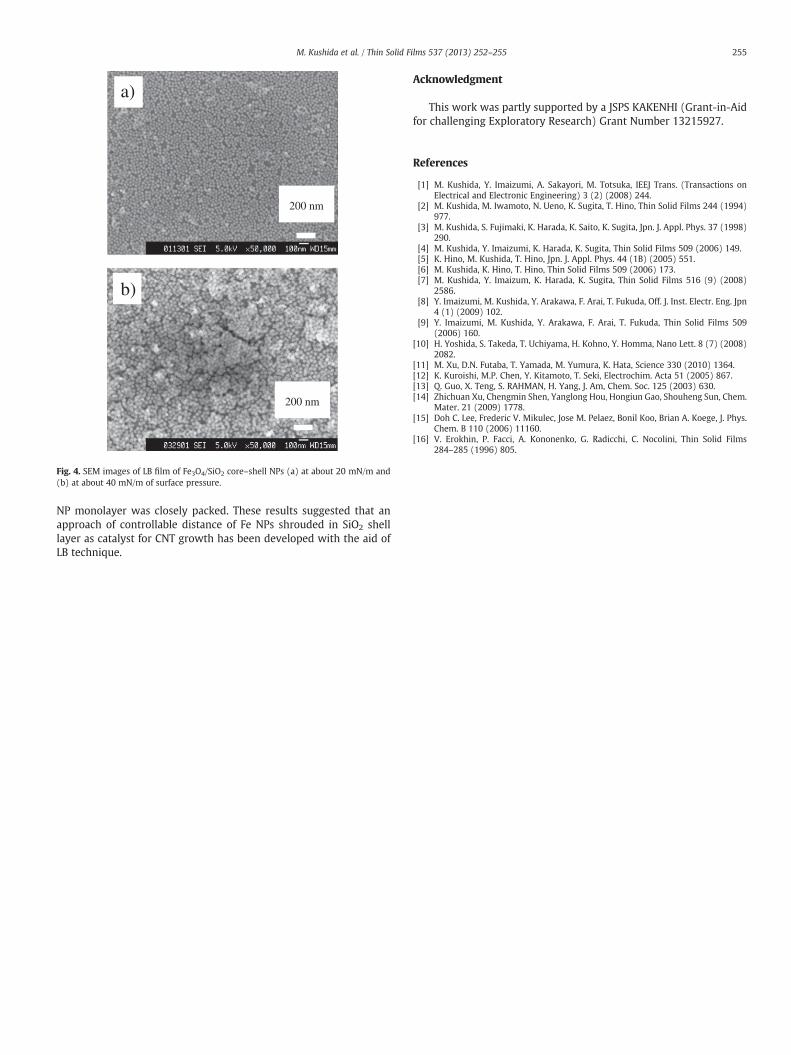
Fe3O4/SiO2 core–shell NP monolayer with vacancies was deposit-ed at 0.0 mN/m of surface pressure from 50 nm2 to 100 nm2 of NParea and 2-D bulk modulus, K, was about 0 mN/m. Fig. 4 (a) showsclear Fe3O4/SiO2 core–shell NPs were observed without coagulationand vacancies in LB film deposited on SiO2/Si substrate at about 20mN/m of surface pressure. As shown in Fig. 3, 2-D bulk modulus, K,was about 250 mN/m of local maximum value at 20 mN/m of surfacepressure. Fe3O4/SiO2 core–shell NP LB films were closely packed [16]at 20 mN/m of surface pressure, and were monolayer as shown inFig. 4 (a).
On the other hand, multilayer like Fe3O4/SiO2 core–shell NPs withcoagulation was observed in LB film deposited on SiO2/Si substrate asshown in Fig. 4 (b) and 2-D bulk modulus, K, was about 0.0 mN/m asshown in Fig. 3 when surface pressure increases from 35 to 55 mN/m.
4. Conclusion
Fe3O4 NPs and Fe3O4/SiO2 core–shell NPs as catalyst for CNTgrowth were synthesized. Almost Fe3O4 NP was retained at the centerof SiO2 shell structure. The thickness of SiO2 shell layer was changedbetween 34 nm and 42 nm. Fe3O4/SiO2 core–shell NP monolayerwithout coagulation and vacancies was deposited on SiO2/Si substrateusing LB technique and maximum of 2-D bulk modulus, K, was about250 mN/m at about 20 mN/m of surface pressure, and this core–shell
200 nm
a)
200 nm
b)
Fig. 4. SEM images of LB film of Fe3O4/SiO2 core–shell NPs (a) at about 20 mN/m and(b) at about 40 mN/m of surface pressure.
255M. Kushida et al. / Thin Solid Films 537 (2013) 252–255
NP monolayer was closely packed. These results suggested that anapproach of controllable distance of Fe NPs shrouded in SiO2 shelllayer as catalyst for CNT growth has been developed with the aid ofLB technique.
Acknowledgment
This work was partly supported by a JSPS KAKENHI (Grant-in-Aidfor challenging Exploratory Research) Grant Number 13215927.
References
[1] M. Kushida, Y. Imaizumi, A. Sakayori, M. Totsuka, IEEJ Trans. (Transactions onElectrical and Electronic Engineering) 3 (2) (2008) 244.
[2] M. Kushida, M. Iwamoto, N. Ueno, K. Sugita, T. Hino, Thin Solid Films 244 (1994)977.
[3] M. Kushida, S. Fujimaki, K. Harada, K. Saito, K. Sugita, Jpn. J. Appl. Phys. 37 (1998)290.
[4] M. Kushida, Y. Imaizumi, K. Harada, K. Sugita, Thin Solid Films 509 (2006) 149.[5] K. Hino, M. Kushida, T. Hino, Jpn. J. Appl. Phys. 44 (1B) (2005) 551.[6] M. Kushida, K. Hino, T. Hino, Thin Solid Films 509 (2006) 173.[7] M. Kushida, Y. Imaizum, K. Harada, K. Sugita, Thin Solid Films 516 (9) (2008)
2586.[8] Y. Imaizumi, M. Kushida, Y. Arakawa, F. Arai, T. Fukuda, Off. J. Inst. Electr. Eng. Jpn
4 (1) (2009) 102.[9] Y. Imaizumi, M. Kushida, Y. Arakawa, F. Arai, T. Fukuda, Thin Solid Films 509
(2006) 160.[10] H. Yoshida, S. Takeda, T. Uchiyama, H. Kohno, Y. Homma, Nano Lett. 8 (7) (2008)
2082.[11] M. Xu, D.N. Futaba, T. Yamada, M. Yumura, K. Hata, Science 330 (2010) 1364.[12] K. Kuroishi, M.P. Chen, Y. Kitamoto, T. Seki, Electrochim. Acta 51 (2005) 867.[13] Q. Guo, X. Teng, S. RAHMAN, H. Yang, J. Am, Chem. Soc. 125 (2003) 630.[14] Zhichuan Xu, Chengmin Shen, Yanglong Hou, Hongiun Gao, Shouheng Sun, Chem.
Mater. 21 (2009) 1778.[15] Doh C. Lee, Frederic V. Mikulec, Jose M. Pelaez, Bonil Koo, Brian A. Koege, J. Phys.
Chem. B 110 (2006) 11160.[16] V. Erokhin, P. Facci, A. Kononenko, G. Radicchi, C. Nocolini, Thin Solid Films
284–285 (1996) 805.