fabrication and three-point-bending behaviour of …
TRANSCRIPT
21st International Conference on Composite Materials
Xi’an, 20-25th August 2017
FABRICATION AND THREE-POINT-BENDING BEHAVIOUR OF
GLASS FIBER REINFORCED THERMOPLASTIC CURVED
CORRUGATED SANDWICH PANEL WITH INTERFACE
ENHANCEMENT
Bing Du1,2, Jingyan Tan1,2, Wenjun Wu1,2 and Liming Chen1,2*
1 College of Aerospace Engineering, Chongqing University, Chongqing 400030, China 2 Chongqing Key Laboratory of Heterogeneous Material Mechanics, Chongqing University,
Chongqing 400030, China
*E-mail: [email protected]
Keywords: Thermoplastic, Curved sandwich panel, Three-point-bending, Interface enhancement
ABSTRACT
Three-point-bending behavior of glass fiber reinforced polypropylene curved corrugated sandwich
panels taking account of the effects of core configurations and interface property were investigated by
experimental method. The curved axial corrugated sandwich panels (CACSP) and curved circular
corrugated sandwich panels (CCCSP) were fabricated by hot-press and adhesive bonding and also
compared with the curved solid panel (CSP) with the same weight. Interface enhancement was
implement by polypropylene glue stick insertion. The experiment results indicated that the
polypropylene glue stick reinforcement is an effective method for curved axial corrugated sandwich
panels. Compared with unenhanced ones, the peak load of polypropylene glue stick reinforced
(PPRGS) CACSP is almost 2 times and the maximum displacement before failure extends to 8 times.
1 INTRODUCTION
Composite sandwich structures haves wide use in many fields such as aerospace, navigation,
transporting and construction etc. for their excellent specific stiffness, strength and multi-functional
properties [1]. Apart from flat ones, curved sandwich panels are also widely used as skins of ships,
aerospace vehicles etc. Some studies of the curved sandwich panel with pyramidal truss core [2, 3],
honeycomb core [4], pyramidal kagome core [5] and foam core [6-9] have been done.
Bending stiffness and strength play a vital role in determining the structural response of composite
sandwich panels. Many studies about the bending behavior of flat composite sandwich panels with
lattice cores have been reported [10-16], but most of which are concerned with fiber reinforced
thermosetting composite. For fiber reinforced thermosetting composite sandwich panels subjected to
three-point-bending, skin fracture tends to render the brittle failure of sandwich panel and leads to that
the residual strength stays at a very low level comparing with the peak load [17, 18]. Schneider et al.
[16] manufactured thermoplastic corrugated sandwich beams made from SrPET (Self-reinforced PET)
with co-curing of core and face sheet. A ductile response after the peak load was found and meanwhile
the load-displacement curve showed softening till a plateau load over the half of peak load was
reached. This ductile response will be beneficial to the energy absorption capacity of thermoplastic
sandwich panel.
The connection within a sandwich system includes adhesive bonding, mechanical fastening or a
combination of both (known as hybrid bonding-fastening). Adhesive bonding is weight-saving and has
lower fabrication cost, improved damage tolerance etc. [19, 20] while mechanical fastening offers the
advantages of easier assembly and disassembly and insensitive to surface preparation and
environmental factors [21]. Hybrid bonding-fastening joint is a selective technique that integrates the
advantages of adhesive bonding and mechanical fastening and finds its wider application in many
industry fields [22]. Apart from the simple adhesive bonding used to fabricate composite sandwich
structures, many attempts have been made to enhance the adhesive bonding strength between face
sheet and lattice core. Xiong et al. [23] added aluminums frames between face sheets and core and
effectively enhanced the shear strength of composite lattice truss core. Fan et al. [24] fabricated

Bing Du, Jingyan Tan, Wenjun Wu and Liming Chen
corrugated lattice truss composite sandwich panels and greatly enhance the shear strength of lattice
sandwich panels without damaging the face sheet. Both of them enhance the interface strength by
enlarging the contact area.
However, to the knowledge of the authors, no research work about the bending behavior of curved
thermoplastic composite corrugated sandwich panel with lattice core has been reported. In present
paper, the three-point-bending tests were conducted to investigate the bending resistance and behavior
of glass fiber reinforced polypropylene (GFRPP) curved corrugated sandwich panels with two core
configurations namely axial and circular ones and different interface connection techniques namely
adhesive bonding and glue stick reinforcement. Firstly, the details of fabrication process and three-
point-bending tests of curved corrugated sandwich panels are presented. Then, the bending resistance
and failure modes of s and CCCSPs fabricated by adhesive bonding along with corresponding CSPs
are investigated. Next, polypropylene glue stick reinforcement is introduced to CACSP and
comparison is made between the reinforced ones and unreinforced ones. Finally, conclusions are
drawn.
2 FABRICATION AND THREE-POINT-BENDING TESTS
2.1 Fabrication
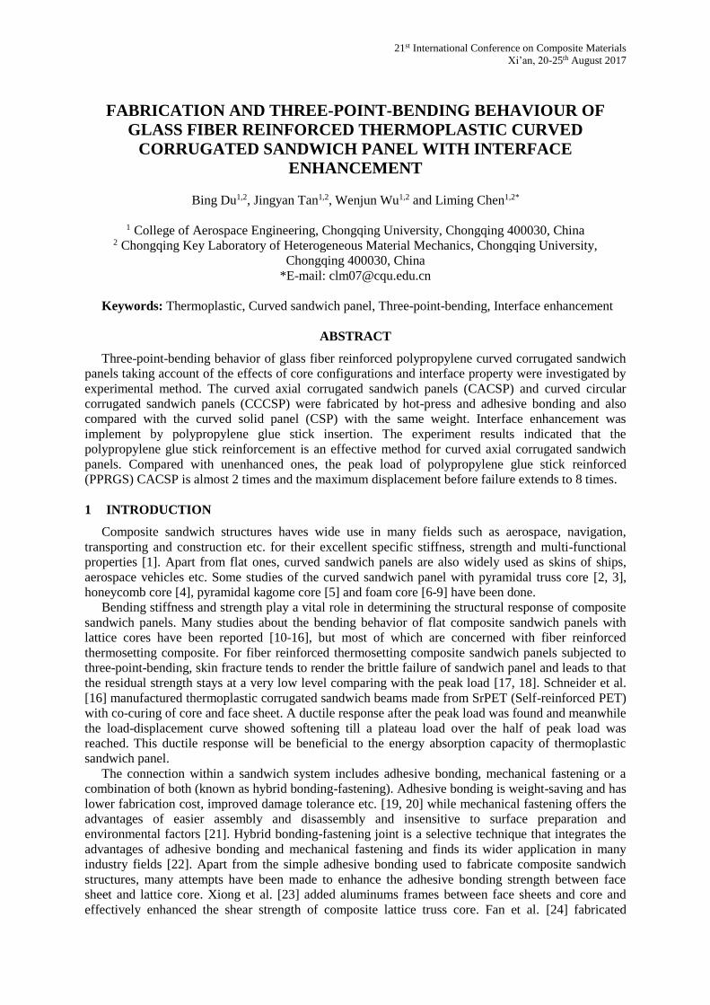
Curved face sheet and two kinds of corrugated cores namely axial and circular were fabricated by
hot press method. Both of counterparts were polished by sand paper and cleaned by ethyl alcohol, then
bonded by adhesive MS1937 (Tonsan Adhesive, Inc.) after careful surface treatment and cured for 3
days with pressure. The property of adhesive and preprep is listed in Table 1 and Table 2 respectively.
Afterwards, the curved sandwich panels were cut into final shape by CNC carving machine and the
schematic is shown in Fig. 1.
Property Value
Density 1.45 g/cm3
Tack free time (@25℃, RH50%) 5-20 min
Cure speed (@25℃, RH50%) 4 mm/24h
Elongation at break (GB/T528) >200%
Tensile strength (GB/T528) 3.0MPa
Shear strength (GB/T7124) 2.3MPa
Table 1: Adhesive property of MS1937 provided by Tonsan Adhesive, Inc..
Property Value
Density 1.5 g/cm3
Weight fraction of fibers 60%
Thickness 0.3 mm
Young’s modulus in longitudinal direction 28 GPa
Young’s modulus in transverse direction 3.2 GPa
In-plane shear modulus 946 MPa
In-plane Poisson’s ratio 0.064
Longitudinal tensile strength 750 MPa
Longitudinal compressive strength 160 MPa
Transverse tensile strength 15 MPa
Transverse compressive strength 50 MPa
Table 2: Property of GFRPP preprep provided by KINGFA Composites.
21st International Conference on Composite Materials
Xi’an, 20-25th August 2017
Figure 1: The fabrication of three kinds of curved panels.
The layup for both of face sheet and core is orthogonal as [0/90]3. For comparison, the CSP with
the same weight was also fabricated with orthogonal layup [0/90]11. It should be noted that local fiber
slip happened to the top layer whose direction was parallel to the circular direction during hot-pressing
for CCCSP. This can be avoided by rearranging the layup of unifiber prepregs to make the top and the
bottom layers with axial direction or used woven fiber prepregs. In this paper, we still used the same
layup for both CACSP and CCCSP for comparison.
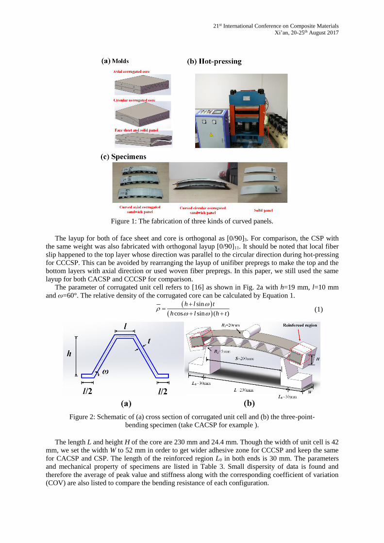
The parameter of corrugated unit cell refers to [16] as shown in Fig. 2a with h=19 mm, l=10 mm
and ω=60°. The relative density of the corrugated core can be calculated by Equation 1.
sin
cos sin ( )
h l t
h l h t
(1)
Figure 2: Schematic of (a) cross section of corrugated unit cell and (b) the three-point-
bending specimen (take CACSP for example ).
The length L and height H of the core are 230 mm and 24.4 mm. Though the width of unit cell is 42
mm, we set the width W to 52 mm in order to get wider adhesive zone for CCCSP and keep the same
for CACSP and CSP. The length of the reinforced region L0 in both ends is 30 mm. The parameters
and mechanical property of specimens are listed in Table 3. Small dispersity of data is found and
therefore the average of peak value and stiffness along with the corresponding coefficient of variation
(COV) are also listed to compare the bending resistance of each configuration.
Bing Du, Jingyan Tan, Wenjun Wu and Liming Chen
Specimen Weight[g] Relative
density
Peak
value[N]
Average peak
value[N]
(COV %)
Stiffness
[N/mm]
Average
stiffness
[N/mm]
(COV %)
CSP-1 144 / 2281 2559
(9.5)
70 80
(11.6) CSP-2 146 / 2736 87
CSP-3 150 / 2659 84
CACSP-1 164 0.136 489 512
(30.2)
143 127
(12.4) CACSP-2 153 0.138 370 112
CACSP-3 158 0.138 677 125
CCCSP-1 164 0.149 1420 1419
(0.1)
330 346
(6.6) CCCSP-2 160 0.156 1417 363
PPGSR
CACSP-1 163 0.112
1122
1013
(11.1)
96
88
(10.1)
PPGSR
CACSP-2 142 0.109
898 90
PPGSR
CACSP-3 164 0.101
1018 79
Table 3: The parameters and mechanical property of specimens
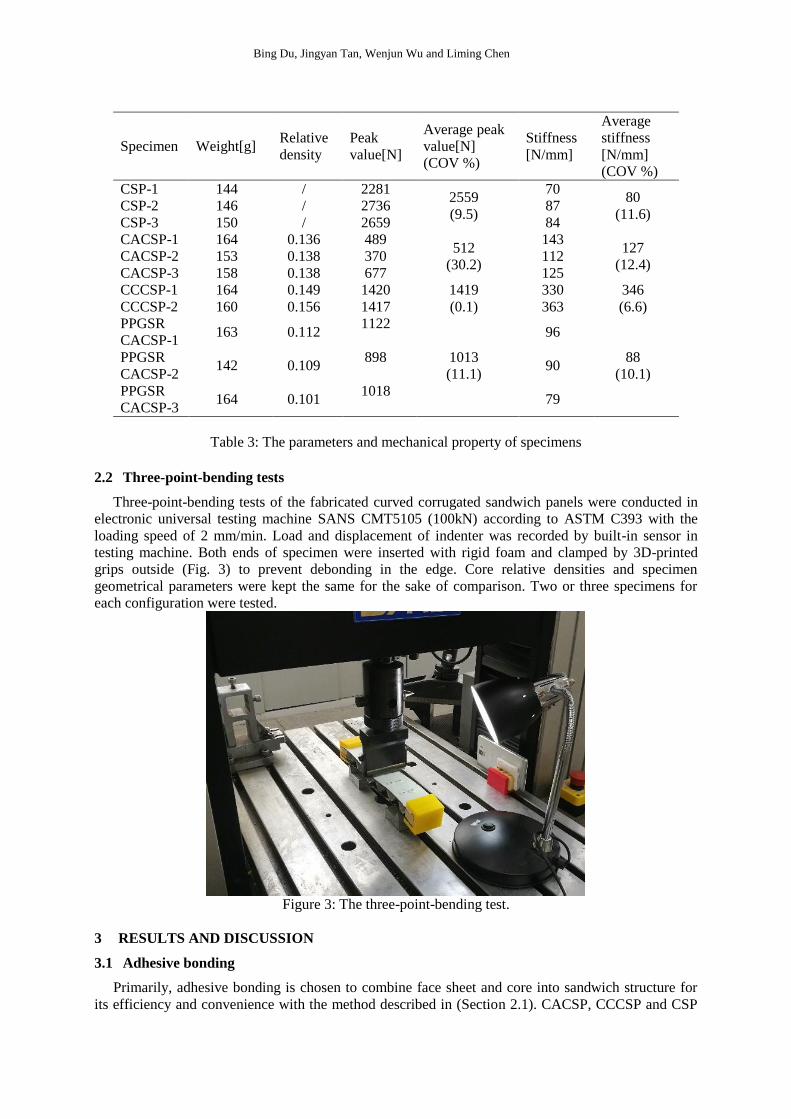
2.2 Three-point-bending tests
Three-point-bending tests of the fabricated curved corrugated sandwich panels were conducted in
electronic universal testing machine SANS CMT5105 (100kN) according to ASTM C393 with the
loading speed of 2 mm/min. Load and displacement of indenter was recorded by built-in sensor in
testing machine. Both ends of specimen were inserted with rigid foam and clamped by 3D-printed
grips outside (Fig. 3) to prevent debonding in the edge. Core relative densities and specimen
geometrical parameters were kept the same for the sake of comparison. Two or three specimens for
each configuration were tested.
Figure 3: The three-point-bending test.
3 RESULTS AND DISCUSSION
3.1 Adhesive bonding
Primarily, adhesive bonding is chosen to combine face sheet and core into sandwich structure for
its efficiency and convenience with the method described in (Section 2.1). CACSP, CCCSP and CSP

21st International Conference on Composite Materials
Xi’an, 20-25th August 2017
were tested and load versus displacement curves were listed in Fig. 4. The peak force and stiffness for
the above three configurations were listed in Table 3. For three CSP specimens cut from the same CSP
sample, one failed due to delamination within the panel with the peak force 2281 N while other two
failed due to fiber breaking in the center of panel with the peak force of 2736 N and 2659 N
respectively. Stiffness varied from 70 N/mm to 87 N/mm. Note that the second specimen showed
highest peak load and stiffness since it is in the center of sample where press and temperature are
relatively well-distributed. Failure modes of three CSP specimens were shown in Fig. 5.
Figure 4: The load versus displacement curves of three kinds of curved panels.
Figure 5: Failure modes of three CSP specimens.
For CACSP, similar relationship between load and displacement was found for three specimens—
an initial linear stage followed by a strength degradation stage resulted from progressive shearing
failure of adhesive as shown in Fig. 6 and 7. Sharp drops on curves appeared during degradation stage
where every drop represented for a debonding between face sheet and unit cell. After each drop, the
load rose gradually on account of face sheet bending till the next extreme load value. That debonding
behavior initiated from the inward one and propagated to outermost one along with the loading of

Bing Du, Jingyan Tan, Wenjun Wu and Liming Chen
upper pressure head resulting in the sidewise unit cell of axial corrugated core flipped instead of
giving firm supporting against the load (Fig. 7). The axial corrugated core can recover after unloading
with no visible damage which means the core hardly contribute much to the bending resistance of
CACSP.
Figure 6: The load versus displacement curves of CACSPs.
Figure 7: The deformation modes of CACSP-3 (numbers correspond to those in Fig. 6).

21st International Conference on Composite Materials
Xi’an, 20-25th August 2017
The peak force and stiffness for three CACSP specimens varied from 370 N to 677 N and 112
N/mm to 143 N/mm. Compared with CSP, stiffness of CACSP increased by 60% while the peak force
dropped nearly 80%. The face sheets are separated by core hence introducing higher cross sectional
moment of inertia for sandwich structure and meanwhile weakening the structural strength in local
loading condition due to material distribution. Hereby, CACSP is weaker but stiffer than CSP with the
same mass.
For CCCSP, the peak force rose to about 1419 N with an obvious crack in the middle of circular
core after which the force dropped down gradually till the local debonding took place resulting in a
cliffy fall as shown (Fig. 8 and 9). Inherent higher bending stiffness compared with axial corrugated
core makes it more strong against three-point-bending – 2.8 times in peak load and 2.7 times in
stiffness. Though peak force decreased by 45%, CCCSP is almost 4.5 times the stiffness of
corresponding CSP.
Figure 8: The load versus displacement curves of CCCSPs.
Figure 9: The deformation modes of CCCSP-1 (numbers correspond to those in Fig. 8).

Bing Du, Jingyan Tan, Wenjun Wu and Liming Chen
3.2 Interface enhancement
Debonding between face sheet and core is the dominant mechanism determining the failure of
fabricated CACSP. In that way, the CACSP only suffered from elastic deformation and still possessed
intact core which can recover after unloading and the maximum load was rather low.
To enhance the interface strength of CACSP for higher load-carrying property, a polypropylene
glue stick with a diameter of 5 mm was used as a pin into every contact area of face sheet and
corresponding part of unit cell to restrict the relative sliding. Firstly, a pre-fabricated hole was drilled
after which no visible crack is observed and the polypropylene stick was cut into desired segments.
Then, put the polypropylene segment into the hole and kept two ends of segment a bit out of the
structure. Finally, used electric soldering iron to melt the polypropylene glue segment and press on it
to form a hat-shaped polypropylene region. There are two polypropylene glue segment locating in the
center of circular direction and equally spaced in axial direction of every contact area. The drilling
process and prepared PPGSR CACSP specimens are shown in Fig. 10. Generally speaking, the inner
part of polypropylene glue segment helps restrict the circular sliding and the outer hat-shaped part
contributes to limit the separation of face sheet and core.
Figure 10: Process (a) drilling and (b) polypropylene glue stick reinforcement and (c)
prepared PPGSR CACSPs.
PPGSR CACSP showed a quiet extended “hardening” stage after the linear stage (Fig. 11).
Different with the sharp drop after linear stage caused by adhesive debonding of CACSP, drops with
small amplitude appeared from approximate 10 mm to 20 mm due to local debonding and its
propagation was found for PPGSR CACSP. Polypropylene glue segments played a vital role in
prohibiting interface debonding from spreading to the whole contact area between face sheet and
corresponding unit cell such that the shear force was transmitted to polypropylene glue segments. Note
that the shear strength is only 3 MPa of adhesive and 39 MPa of polypropylene. Accordingly, the
bending resistance both in load-carrying limit and maximum displacement before failure of CACSP
was much higher enhanced (Fig. 11), even corresponded to CSP in maximum displacement before
failure. It shown that sandwich effect became prominent after reinforcing while stiffness was slightly
lower than that of CACSP because of the drilling holes upon the face sheets.

21st International Conference on Composite Materials
Xi’an, 20-25th August 2017
Figure 11: The load versus displacement curves of PPGSR CACSPs along with those of
CACSPs.
The typical failure modes of PPGSR CACSPs, namely core crushing, global slip and face sheet
crushing, were listed in Fig. 12. For PPGSR CACSP specimen 1, sharp drop was also found at ~37
mm due to the crushing of central unit cell. Along with the loading, the load increased till another
abrupt drop was met due to the global slip between pressure head and specimen on account of hat-
shaped regions (Fig. 12b). Afterwards, the face sheet become the main load-carrying part and is
crushed in the end (Fig. 12c). For specimen 2, global slip and face sheet crushing appeared while only
global slip was found for specimen 3. Notably, no damage of polypropylene glue stick and area
surrounded is found
Figure 12: Typical failure modes of PPGSR CACSPs.

Bing Du, Jingyan Tan, Wenjun Wu and Liming Chen
Besides, PPGSR method was conducted on the tested CACSP with interface debonding to
distinguish the contribution of PPGSR method and adhesive bonding method. The load versus curve
and the deformation is not listed here for brevity. The peak load and stiffness are 849 N and 94 N/mm
respectively which are close to those average values of CACSPs namely 1013 N and 88 N/mm. It
indicated that PP glue stick is the determining factor for CACSP specimens subjected to three-point-
bending. Parametric study such as the material and spatial distribution of glue stick using finite
element analysis and analytical prediction concerning different failure modes will need conducting in
this vein.
4 CONCLUSIONS
Two kinds of curved corrugated sandwich panels with axial and circular cores along with solid
panels were fabricated by hot-pressing method. Three-point-bending testing was conducted to
investigate the effects of configurations and interface property on structural bending resistance and
deformation.
1) Among the three configurations, solid panel are found to possess the highest peak load as 5
times as curved axial corrugated sandwich panel and almost as 2 times as curved circular one. On the
contrary, the stiffness of solid panel is the lowest with the value of 80 N/mm while those of curved
corrugated sandwich panel with axial and circular cores are 127 N/mm and 346 N/mm respectively
due to higher cross sectional moment of inertia.
2) Adhesive bonding strength is a critical factor which limits the peak force of curved corrugated
sandwich panel subjected to three-point-loading especially for the axial ones. The curved axial
corrugated core merely suffered from recoverable deformation and remained almost intact after
unloading while local indentation appeared to the front face sheet. In that way, it is not a desirable
choice since not all material in sandwich panel contribute to resisting deformation and carrying load.
3) Polypropylene glue stick reinforcement is an effective method to enhance the interface
strength and further heighten the bending resistance of curved axial corrugated sandwich panel.
Polypropylene is the same material with matrix used in the curved structures above which makes it
possible to recycle the whole structure without other component different from original fiber and
matrix. Note that polypropylene is a widely used thermoplastic polymer with relatively low strength in
engineering fields. Other stronger thermoplastic polymer such as polyethylene terephthalate (PET),
polyoxymethylene (POM) and so on, can be candidates for reinforced stick if stronger material is used
for sandwich structure and better structural performance is expected.
4) After introducing polypropylene glue stick reinforcement, the resisting region before failure is
quite extended where load also remains at a higher level which is beneficial for the bending resistance
of curved axial corrugated sandwich panel. Though higher peak load value is reached for curved
circular corrugated sandwich panel compared with axial one, gradually collapse of structure is
observed after initial failure and the load stays in a low level. It can be reasonable choice to use glue
stick reinforcement method to improve structural performance in the latter stage of loading for curved
circular corrugated sandwich panel.
ACKNOWLEDGEMENTS
Supports from the National Natural Science Foundation of China (11572059, 11302270 and
11632004), Chongqing Natural Science Foundation (cstc2013jcyjA00030), Ph.D. Programs
Foundation of Ministry of Education of China (20130191120015) and State Key Lab for Strength and
Vibration of Mechanical Structures of Xi’an Jiaotong University (SV2015-KF-12) are gratefully
acknowledged.
REFERENCES
[1] H.N.G. Wadley, Multifunctional periodic cellular metals, Philosophical Transactions of The Royal
Society A: Mathematical, Physical and Engineering Materials, 364, 2006, pp. 31-68(doi:
10.1098/rsta.2005.1697).
[2] J.S. Yang, L. Ma, C.V. Mauricio, T.X. Huang, K.U. Schröder, R. Schmidt, L.Z. Wu, Influence of
manufacturing defects on modal properties of composite pyramidal truss-like core sandwich cylindrical

21st International Conference on Composite Materials
Xi’an, 20-25th August 2017
panels, Composites Science and Technology, 147, 2017, pp. 89-99(doi:
10.1016/j.compscitech.2017.05.007).
[3] J. Xiong, R. Ghosh, L. Ma, H. Ebrahimi, A.M.S. Hamouda, A. Vaziri and L.Z. Wu, Bending behavior of
lightweight sandwich-walled shells with pyramidal truss cores, Composite Structures, 116, 2014, pp.793-
804(doi: 10.1016/j.compstruct.2014.06.006).
[4] J. Klos, J.H. Robinson, R.D. Buehrle, Sound Transmission Through a Curved Honeycomb Composite
Panel, Proceedings of the 9th AIAA/CEAS Aeroacoustics Conference and Exhibit. Hillton Head, South
Carolina, 12-14 May 2003. #AIAA-2003-3157(doi: 10.2514/6.2003-3157).
[5] J.S. Hwang, T.G. Choi, D.Y. Lee, M.Y. Lyu, D.G. Lee, D.Y. Yang, Development of a bendable
pyramidal kagome structure and its structural characteristics, Composite Structures, 142, 2016, pp. 87-
95(doi: 10.1016/j.compstruct.2016.01.079).
[6] B.O. Baba, S. Thoppul, Experimental evaluation of the vibration behavior of flat and curved sandwich
composite beams with face/core debond, Composite Structures, 91, 2009, pp. 110-109(doi:
10.1016/j.compstruct.2009.04.037).
[7] B.O. Baba, S. Thoppul, R.F. Gibson, Experimental and Numerical Investigation of Free Vibrations of
Composite Sandwich Beams with Curvature and Debonds, Experimental Mechanics, 51, 2010, pp. 857-
868(doi: 10.1007/s11340-010-9388-5).
[8] B.O. Baba, Impact response of sandwich beams with various curvatures and debonds, Journal of
Sandwich Structures and Materials, 15, 2013, pp. 137-155(doi: 10.1177/1099636212460543).
[9] R.M. Guedes, A. Sá, Numerical analysis of singly curved shallow composite panels under three-point
bend load, Composite Structures, 83, 2008, pp. 212-220(doi: 10.1016/j.compstruct.200704.005).
[10] J. Xiong, L. Ma, S.D. Pan, L.Z. Wu, J. Papadopoulos, A. Vaziri, Shear and bending performance of
carbon fiber composite sandwich panels with pyramidal truss cores, Acta Materialia, 60, 2012, pp. 1455-
1466(doi: 10.1016/j.actamat.2011.11.028).
[11] J. Xiong, L. Ma, A. Stocchi, J.S. Yang, L.Z. Wu, S.D. Pan, Bending response of carbon fiber composite
sandwich beams with three dimensional honeycomb cores, Composite Structures, 108, 2014, pp. 234-
242(doi: 10.1016/ j.compstruct.2013.09.035).
[12] H.L. Fan, F.H. Meng, W. Yang, Sandwich panels with Kagome lattice cores reinforced by carbon fibers,
Composite Structures, 81, 2007, pp. 533-539(doi: 10.1016/j.compstruct.2006.09.011).
[13] H.L. Fan, L. Yang, F.F. Sun, D.N. Fang, Compression and bending performances of carbon fiber
reinforced lattice-core sandwich composites, Composites Part A: Applied Science and Manufacturing, 52,
2013, pp. 118-125(doi: 10.1016/j.compstruct.2013.04.013).
[14] F.N. Jin, H.L. Chen, L. Zhao, H.L. Fan, C.G. Cai, N. Kuang, Failure mechanisms of sandwich composites
with orthotropic integrated woven corrugated cores: Experiments, Composite Structures, 98, 2013, pp.
53-58(doi: 10.1016/j.compstruct.2012.09.056).
[15] G.D. Xu, F. Yang, T. Zeng, S. Cheng, Z.H. Wang, Bending behavior of graded corrugated truss core
composite sandwich beams, Composite Structures, 138, 2016, pp. 342-351(doi:
10.1016/j.compstruct.2015.11.057).
[16] C. Schneider, D. Zenkert, V.S. Deshpande, S. Kazemahvazi, Bending energy absorption of self-
reinforced poly(ethylene terephthalate) composite sandwich beams, Composite Structures, 140, 2016, pp.
582-589(doi: 10.1016/j.compstruct.2015.12.043).
[17] H.L. Fan, H.L. Chen, L. Zhao, J.N. Zhou, F.N. Jin, J.J. Zheng, N. Kuang, Flexural failure mechanisms of
three-dimensional woven textile sandwich panels: Experiments, Journal of Composite Materials, 48,
2014, pp. 609-620(doi: 10.1177/0021998313476326).
[18] H.L. Fan, Q. Zhou, W. Yang, J.J. Zheng, An experiment study on the failure mechanisms of woven
textile sandwich panels under quasi-static loading, Composites Part B: Engineering, 41, 2010, pp. 686-
692(doi: 10.1016/j.compsitesb.2010.07.004).
[19] L.F.M.D Silva, M.D. Banea, Adhesively bonded joints in composite materials: an overview, Proceedings
of the Institution of Mechanical Engineers, Part L: Journal of Materials: Design and Applications, 223,
2009, pp. 1-18(doi: 10.1243/14644207JMDA219).
[20] S. Budhe, M.D. Bane, S.D. Barros, L.F.M.D. Silva, An updated review of adhesively bonded joints in
composite materials, International Journal of Adhesion and Adhesives, 72, 2017, pp. 30-42(doi:
10.1016/j.ijadhadh.2016.10.010).

Bing Du, Jingyan Tan, Wenjun Wu and Liming Chen
[21] S.D. Thoppul, J. Finegan, R.F. Gibson, Mechanics of mechanically fastened joints in polymer–matrix
composite structures – A review, Composites Science and Technology, 69, 2009, pp. 301-329(doi:
10.1016 /j.compscitech.2008.09.037).
[22] K. Bodjona, L. Lessard, Hybrid bonded-fastened joints and their application in composite structures: A
general review, Journal of Reinforced Plastics and Composites, 35, 2016, pp. 764-781(doi:
10.1177/0731684415627296).
[23] Q.Q. Wu, L. Ma, L.Z. Wu, J. Xiong, A novel strengthening method for carbon fiber composite lattice
truss structures, Composite Structures, 153, 2016, pp. 585-592(doi: 10.1016/j.compstruct.2016.06.060).
[24] Y. Hu, W.X. Li, X.Y. An and H.L. Fan, Fabrication and mechanical behaviors of corrugated lattice truss
composite sandwich panels, Composites Science and Technology, 125, 2016, pp. 114-122(doi:
10.1016/j.compscitech.2016.02.003).