fabrication and characterization of …eprints.uthm.edu.my/9891/1/muhammad_luqman_mohd_napi.pdf ·...
TRANSCRIPT
FABRICATION AND CHARACTERIZATION OF
NANOSTRUCTURED FLUORINE DOPED TIN
OXIDE THIN FILM FOR DSSC BY
HYDROTHERMAL METHOD
MUHAMMAD LUQMAN BIN MOHD NAPI
UNIVERSITI TUN HUSSEIN ONN MALAYSIA

i
FABRICATION AND CHARACTERIZATION OF NANOSTRUCTURED
FLUORINE DOPED TIN OXIDE THIN FILM FOR DSSC BY
HYDROTHERMAL METHOD
MUHAMMAD LUQMAN BIN MOHD NAPI
A thesis submitted in
fulfillment of the requirement for the award of the
Degree of Master in Electrical Engineering
Faculty of Electrical and Electronic Engineering
Universiti Tun Hussein Onn Malaysia
January 2017

iii
To my beloved parents

iv
ACKNOWLEDGEMENTS
My most humble and sincere thanks to my supervisor Dr Mohd Khairul
Ahmad, Head of Solar Cell laboratory, MiNT-SRC, University Tun Husseein Onn
Malaysia for his advice and guidance me entire in this research work.
The entire team at MiNT-SRC with very special thanks especially to Pn
Faezahana and Miss Esri Hetti for their efforts and energy, all my samples
experiment were able to be characterized on time.
To the incredible labmates, I would like to thank Pn Sakinah, Pn Kamalia,
Asyikin Syasya, Fatin Izyani, Salina Mokhtar, Liyana and Kim Seng for all their
support on me. Last, I’m very gratefull to my family for their patience that always
supported me to finish this research.

v
LIST OF PUBLICATIONS
1 M. L. M. Napi, N. Nayan, M. K. Ahmad, F. I. M. Fazlee, N. K. A. Hamed, &
N. S. Khalid, “Fabrication of Flourine Doped Tin Oxide With Different
Volume Of Solvents On FTO Seed Layer by Hydrothermal Method”, Sains
Malaysiana, vol. 45, no. 8, pp. 1207-1211 (2016).
2 F. I. M Fazli, N. Nayan, M. K. Ahmad, M. L. M. Napi, N. K. A. Hamed & N.
S. Khalid, “Effect of Annealing Temperature on TiO2 Thin Films prepared by
Spray Pyrolysis Deposition Method”, Sains Malaysiana, vol. 45, no. 8,
pp.1197-1200 (2016).
3 N. K. A. Hamed, N. Nayan, M. K. Ahmad, N. S. Khalid, F. I. M. Fazli, & M.
L. M. Napi,“Influence of Hydrochloric Acid Volume on the growth of
Titanium Dioxide (TiO2) Nanostructures by Hydrothermal Method”, Sains
Malaysiana. (in review)
4 N. S. Khalid, N. Nayan, M. K. Ahmad. C. F. Soon, M. L. M. Napi, N. K. A.
Hamed, & F. I. M. Fazli, “Biocompatibility of TiO2 Nanorods and
Nanoparticles on HeLa cells”, Sains Malaysiana. (in review)
5 M. K. Ahmad, M. L. M. Napi, N. F. Izyani, C. F. Soon, N. Nafarizal, A. B.
Suriani, A. Mohamed, M. H. Mamat, M. F. Malek, M. Shimomura, & K.
Murakami, “A Facile Method for Synthesis of Nanorice Fluorine Doped Tin
Oxide for use in Dye-Sensitized Solar Cells”, Materials Letters. (in review)
6 M. L. M. Napi, M. F. Maarof, C. F. Soon, N. Nayan, F. I. M. Fazli, N. K. A.
Hamed, S. M. Mokhtar, N, K, Seng, M. K. Ahmad, A. B. Suriani, & A.
Mohamed, “Fabrication of Fluorine Doped Tin Oxide (FTO) Thin Films
Using Spray Pyrolysis Deposition Method For Transparent Conducting
Oxide”, ARPN Journal of Engineering and Applied Sciences (JEAS), Vol. 11,
no. 14, pp. 8800-8804 (2016).
vi
7 F. I. M. Fazli, A. N. Suhaimi, N. S. Khalid, N. K. A. Hamed, M. L. M.
Luqman, S. M. Mokhtar, N. K. Seng, N. Zainal, N. Nayan, S. C. Fhong, A.
B. Suriani & M. K. Ahamd, “The Effects Of Annealing Temperature On
Properties Of Aluminium-Doped Tin Oxide (Al/SnO2) Thin Films Deposited
By Spray Pyrolysis Deposition (SPD) Method”, ARPN Journal of
Engineering and Applied Sciences (JEAS), vol. 11, no. 14, pp. 8840-8845
(2016).
8 S. M. Mokhtar, M. K. Ahmad, N. M. A. N. Ismail, M. S. Mamat, F. I. M.
Fazli, N. K. A. Hamed, M. L. M. Napi, N. S. Khalid, N. K. Seng. N. Zainal,
S. C. Fhong, N. Nayan, & A. B. Suriani, “Fabrication Of Co/SnO2 On Glass
Substrate Using Spray Pyrolysis Deposition Technique With Variation Of
Annealing Temperature”, ARPN Journal of Engineering and Applied
Sciences (JEAS), vol. 11, no. 14, pp. 8873-8877 (2016).
9 M. L. M. Napi, N. K. Seng, & M. K. Ahmad, “Surface Morphology and
Electrical Properties of FTO (Fluorine Doped Tin Oxide) with Different
Precursor Solution for Transparent Conducting Oxide”, Applied Mechanics
and Materials, vols. 773-774, pp. 682-685, (2015).

vii
ABSTRACT
Nanostructured Fluorine Doped Tin Oxide (FTO) thin film has been
successfully synthesized on top of bare FTO layer substrates using hydrothermal
method. The performance of FTO thin film including conductivity and transparency
depend on the surface morphology and the properties of the material. Hydrothermal
method has proven to be a very good method for the fabrication of novel metal
oxides. Thus, a new nanostructured FTO thin film like nanorice has been fabricated
using one step hydrothermal method. FTO nanorice thin films were obtained from
the reaction of tin (iv) chloride (SnCl4), ammonium fluoride (NH4F), acetone,
deionized water and hydrochloric acid (HCl). The compound was prepared in an
autoclave at 150°C hydrothermal temperature for different reaction times of 5 hours,
10 hours, 15 hours, and 20 hours. FESEM studies on the surface morphologies of all
the samples showed that nanorice structure had formed to fully cover the bare FTO
substrate. Then, to further the optimization of FTO nanorice thin film, this research
focused on studying the effect of hydrothermal temperature on FTO nanorice thin
films. The experiments were conducted at 130°C, 140°C, 150°C, 160°C, and 170°C
of hydrothermal temperature in constant reaction time of 10 hours. Basically, there
were six properties studied; surface morphology, structural, element composition,
thickness measurement, electrical and optical properties. At the end of this research,
homogeneous FTO thin film has been successfully prepared. By controlling the
reaction time and hydrothermal temperature, a transparent FTO film with beyond
85% percentage of transmittance was developed. The FTO thin film produced at 10
hour reaction time and 150°C of hydrothermal temperature time gave the low sheet
resistance of 0.012 Ohm/sq with high transparency. The DSSC fabricated using the
optimized FTO film gave higher efficiency of 2.77% compared to commercial FTO
of 1.93%.

viii
ABSTRAK
Nanostruktur Fluorin Dop Stanum Oksida (FTO) tipisan nipis telah berjaya
disintesiskan di atas lapisan FTO substrat yang kosong menggunakan kaedah
hidroterma. Bagi prestasi FTO tipisan nipis yang meliputi kekonduksian dan
kelutsinaran bergantung pada morfologi permukaan dan juga sifat-sifat bahan
tersebut. Kaedah hidroterma telah terbukti menjadi satu kaedah yang sesuai untuk
pemfabrikasi logam oksida yang baharu. Demikian itu, satu jenis nanostruktur FTO
tipisan nipis seperti nanonasi telah berjaya difabrikasi menggunakan satu peringkat
kaedah hidroterma. FTO nanonasi tipisan nipis diperolehi daripada reaksi antara
timah (iv) klorida, ammonium fluoride, aseton, air ternyahion, dan asid hidroklorik.
Sebatian itu disediakan di dalam autoklaf di suhu hidroterma iaitu 150°C pada
tempoh masa tindak balas yang berbeza beza iaitu 5 jam, 10 jam, 15 jam dan 20 jam.
Penelitian FESEM menunjukkan bahawa ada perubahan atas permukaan morfologi
iaitu struktur nanonasi telah menutupi FTO substrat kosong. Seterusnya, untuk
mengoptimumkan lagi FTO nanonasi tipisan nipis, kajian ini telah memfokuskan
kepada kesan suhu hidroterma terhadap FTO nanonasi tipisan nipis. Eksperimen-
eksperimen telah dijalankan pada pelbagai suhu hidroterma iaitu 130°C, 140°C,
150°C, 160°C dan 170°C pada satu tempoh masa tindak balas yang tetap iaitu 10
jam. Secara asasnya, terdapat enam ciri yang diteliti; morfologi permukaan, struktur,
komposisi elemen, pengukuran ketebalan, sifat elektrik dan optik. Dipenghujung
kajian ini, FTO tipisan nipis yang homogen berjaya disediakan. Dengan mengawal
masa reaksi dan suhu hidroterma, FTO yang lutsinar telah dijayakan dengan melebihi
85% transmisinya. FTO tipisan nipis yang menggunakan 10 jam masa reaksi pada
150°C suhu hidroterma mempunyai rintangan keping yang rendah iaitu sebanyak
0.012 Ohm/sq dengan kelutsinaran yang tinggi. DSSC telah difabrikasi
menggunakan FTO nanonasi yang optimum ini dan memberikan kecekapan yang
tinggi iaitu 2.77% dibandingkan dengan komersial FTO iaitu 1.93%.

ix
TABLE OF CONTENTS
TITLE i
DECLARATION ii
DEDICATION iii
ACKNOWLEDGEMENT iv
LIST OF PUBLICATIONS v
ABSTRACT vii
ABSTRAK viii
TABLE OF CONTENTS ix
LIST OF FIGURES xii
LIST OF TABLES xv
LIST OF ABBREVIATION xvi
CHAPTER 1 INTRODUCTION
1.1 Introduction 1
1.2 Research background 2
1.3 Problem statements 4
1.4 Objectives 5
1.5 Scope 6
CHAPTER 2 LITERATURE REVIEW
2.1 Transparent conducting oxide 7
2.2 Fluorine doped tin oxide 10
2.2.1 Precursors for FTO films preparation 14
2.3 Hydrothermal method 15
2.4 Dye-Sensitized Solar Cell 16

x
2.4.1 Titanium dioxide 17
2.4.2 Dyes 19
2.4.3 Electrolytes 22
2.4.4 Counter electrode 23
2.5 Summary of literature review 24
CHAPTER 3 METHODOLOGY
3.1 Introduction 25
3.2 FTO fabrication process 27
3.3 Preparation of DSSC 30
3.4 Characterization of sample 32
3.4.1 Field emission scanning electron
microscopy (FESEM)
32
3.4.2 X-ray diffractometer (XRD) 35
3.4.3 Two point probe method 36
3.4.4 Energy-dispersive spectroscopy (EDX) 37
3.4.5 UV-VIS spectrophotometer 38
3.4.6 Surface profiler 39
3.4.7 Solar simulator 41
CHAPTER 4 RESULTS AND DISCUSSION
4.1 Effect of reaction time to the properties of the
nanostructured FTO films
42
4.1.1 Introduction 42
4.1.2 Surface morphology 43
4.1.3 Structural analysis 48
4.1.4 Element composition 49
4.1.5 Electrical properties 50
4.1.6 Optical properties 53
4.1.7 Summary 56

xi
4.2 Effect of hydrothermal temperature to the
properties of the nanostructured FTO films
57
4.2.1 Introduction 57
4.2.2 Surface morphology 57
4.2.3 Structural analysis 62
4.2.4 Element composition 63
4.2.5 Electrical properties 65
4.2.6 Optical properties 66
4.2.7 Summary 67
4.3 Power conversion efficiency measurement 68
CHAPTER 5 CONCLUSION AND FUTURE WORK
5.1 Conclusion 72
5.2 Future work 73
REFERENCES 74
VITAE 85

xii
LIST OF FIGURES
2.1 The application of TCO 9
2.2 Ball and stick of the structure of SnO2 11
2.3 The schematic drawing of the SnO2 films at early stage
formed by the SPD process
11
2.4 FESEM image of SnO2 nanoflower films 13
2.5 The DSSC working components 17
2.6 The structure bonding of rutile and anatase of TiO2 thin
films
18
27 Molecular structure of various of metal-complexes dye
with efficiency
20
2.8 Working mechanism of metal-free organic dye. Do and
Acc denote donor and acceptor, respectively.
21
2.9 Classification of electrolyte for DSSC 23
3.1 Flow chart of the methodology 26
3.2 Flow chart of the substrates cleaning 27
3.3 Precursor solution preparation 28
3.4 Schematic diagram of an autoclave and sample prepared 29
3.5 The autoclave containing substrates and precursor
solution are put in oven to conduct the hydrothermal
process
29
3.6 The process flow of TiO2 preparation on FTO nanorice
films. (a) Preparation of TiO2 solution (b) The TiO2
solution were sprayed on nanostructured FTO films (c)
The TiO2 fabricated on FTO nanorices are annealed at
450°C in 1 hour and (d) The sample allowed to cool in
room temperature
31
3.7 Picture of Field Emission Scanning Electron Microscope 32
3.8 Illustration of sample stage 33
3.9 (a) Specimen stage control panel, (b) Operation panel 34

xiii
3.10 Picture of X-ray diffractometer 35
3.11 Diagram of I-V measurement 36
3.12 EDX working components 37
3.13 Picture of UV-VIS spectrophotometer 38
3.14 Sample compartment of UV-Vis spectrophotometer 39
3.15 The schematic illustration of thickness measurement
using surface profiler (put in methodology)
40
3.16 Picture of surface profiler 40
3.17 Picture of Solar Simulator 41
4.1 FESEM images view of FTO films at x100k
magnification with different reaction time. (a) bare FTO
films, and FTO nanorice films obtained at reaction times
of (b) 5 hours, (c) 10 hours, (d) 15 hours and (e) 20 hours.
44
4.2 FESEM image view at x25k magnification of FTO with
different reaction time. (a) bare FTO substrate, and FTO
nanorice films obtained at reaction times of (b) 5 hours,
(c) 10 hours, (d) 15 hours and (e) 20 hours. (f) Cross-
sectional view of FESEM images of FTO nanorice films
obtained by hydrothermal method for 10 hours reaction
time.
46
4.3 Variation of the thickness of FTO films (mean and SE)
deposited at different reaction time.
47
4.4 XRD spectrum of FTO film deposited at (a) 5 hours, (b)
10 hours, (c) 15 hours, (d) 20 hours of reaction time
respectively and (e) bare FTO substrate
48
4.5 EDX spectrum of FTO films prepared at (a) 5 hours, (b)
10 hours, (c)15 hours and (d) 20 hours reaction time
50
4.6 The graph of sheet resistance for experiment conducted at
5, 10, 15 and 20 hours of reaction time.
52
4.7 The transmittance spectra of FTO films deposited at (a) 5
hours, (b) 10 hours, (c) 15 hours, (d) 20 hours of reaction
time respectively and (e) bare FTO substrate.
54

xiv
4.8 Schematic diagram of growth mechanism for FTO
nanorice films
54
4.9 FESEM image view at x100k magnification of FTO with
different hydrothermal temperature at (a) 130°C, (b)
140°C, (c) 150°C, (d) 160°C, and (e) 170°C
59
4.10 FESEM image view at x25k magnification of FTO with
different hydrothermal temperature (a) 130°C, (b) 140°C,
(c) 150°C, (d) 160°C, and (e) 170°C.
60
4.11 Variation of the thickness of FTO films with standard
error for the films deposited at different hydrothermal
temperature
61
4.12 XRD spectrum of FTO nanorice films at (a) 130°C (b)
140°C (c) 150°C (d) 160°C and (e) 170°C of
hydrothermal temperature
62
4.13 EDX spectrum of FTO nanorice film (a) 130°C (b)
140°C (c) 150°C (d) 160°C and (e) 170°C of
hydrothermal temperature
64
4.14 The graph of sheet resistance for experiment conducted at
130°C, 140°C, 150°C, 160°C and 170°C of hydrothermal
temperature.
66
4.15 Transmittance curves of the FTO nanorice films prepared
by varying the hydrothermal temperature (a) 130°C,
(b)140°C, (c) 150°C (d)160°C and (e) 170°C.
67
4.16 FESEM image of TiO2 nanoparticle (a) top view at 200k
magnification (b) cross section view at 5k magnification
68
4.17 The condition of the samples of FTO nanorice/TiO2
before and after immersion in dye for 15 hours.
69
4.18 I-V characteristics of DSSC using TCO of FTO
commercial film and FTO nanorice film
71

xv
LIST OF TABLES
2.1 History of processes for making transparent conductors 8
2.2 I-V measurement of DSSC based on various type of
natural dye
22
4.1 The resistivity and sheet resistance of FTO films prepared
on bare FTO substrate from different reaction time
52
4.2 The resistivity and sheet resistance of FTO films prepared
from different hydrothermal temperature
65
4.3 Comparision of open-circuit voltage (VOC), short-circuit
current density (JSC), Fill Factor and efficiency between
commercial FTO films and FTO nanorice film prepared
71

xvi
LIST OF ABBREVIATION
A - Cross sectional area
η - Efficiency
I - Current
k - Kilo
L - Length
ρ - Resistivity
R - Resistance
RS - Sheet resistance
t - Thickness
V - Voltage
DSSC - Dye sensitized solar cells
FTO - Flourine doped tin oxide
HCl - hydrochloric acid
SnCl4 - Tin (iv) chloride
TCO - Transpaerent conducting oxide
TiO2 - Titanium dioxide
UTHM - Universiti Tun Hussein Onn Malaysia
ZnO - Zinc Oxide

1
CHAPTER 1
INTRODUCTION
1.1 Introduction
The electrical energy generated from fossil fuels has become the major factor in the
development of civilization from day to day. The generated energy produced by
every country would affect the level of industrial and agricultural growth. Thus,
sustainable economy in one country depends on the energy that has been conserved
constantly. The high supplied of fossil fuels would contribute to the economic wealth
and the materials standards of a nation. However, the widely usage of fossil fuels
also would lead to the environmental and ecology changes [1]. As the increasing
energy demand, the environmental friendly alternatives, renewable and non-
conventional sources are being searched by many countries [2].
One of the potential sources of renewable energy is solar energy. Solar
energy is an effective energy and become an important source of energy because this
is the one of the energies that could be used after depletion of another source such as
fossil fuels. As solar cells have high commercialization, the variety of technologies
which used solar cells have been improved in the research of solar energy.
Solar cell is a photovoltaic device which is basically used to convert solar
radiation to electricity based on photosynthesis concept of sunlight. The solar cell is
very useful because of its ability to generate the electricity which have been
thoroughly discussed in several recent reports [3, 4]. One of the solar cell types is
Dye-Sensitized Solar Cell (DSSC) which comprises of five components. They are
transparent conducting oxide, semiconductor film, sensitizer adsorber onto the
surface of semiconductor, electrolyte and counter electrode [5].
Basically, there are three categories of solar cell. First and foremost is the
silicon based solar cell. This type of solar cell is the most popular but expensive due
to the high manufacturing cost and limited availability of silicon make to find

2
alternative material of solar cell. The second generation of solar cell is called thin
film solar cells, which is cheaper than the first generation. However the power
conversion efficiency of second solar cell is still low. The DSSC is the third
generation of solar technology. It provides effective charge separation that allows
electricity to be generated even though in low light condition. The first DSSC was
invented at 1991 based on artificial photosynthesis system to generate electricity [6].
Currently, DSSC is still in research phase to enhance its efficiency. The average
efficiency of this new type of solar cell is 15% [5, 7]. Overall DSSC is considered as
a low cost, simple and a promising technique to provide high performance of
electrical generation. Furthermore, the cost of manufacturing of this DSSC is much
lower compared to the first and second generations solar cell.
1.2 Research Background
Tin oxide (SnO2) is a n-type semiconductor with band-gap energy of 3.6eV. A thin
films of SnO2 is transparent in the visible region and reflecting in the high infrared
region [8]. The conductivity of the material is mainly attributed due to the oxygen
vacancies in the lattice whose structure is tetragonal and similar to the rutile structure
[9]. Conductivity of SnO2 can further be increased by doping it with element group
III, V, VI and VII of the periodic table; some of which are Ti, Sb, Te and F. Among
these elements, the most widely used dopant is flourine because of the fact that the
resultant flourine doped tin oxide (FTO) film is highly stable chemically and
thermally [10, 11]. FTO thin film has been used mainly for electronics devices. The
performance of FTO films can be increased with highly crystalline and larger surface
area [5]. According to above concept, FTO film with one-dimensional nanoparticle
size could give high surface areas for better electron mobility and less electron
recombination. It is known in the realm of nanoscience and nanotechnology that
nanorods, nanowires and nanotubes have special roles because of their
dimensionality. When the diameter of the nanorods, nanowires and nanotubes
become small, the physical and chemical properties of the one-dimensional
nanostructure are clearly different from those of crystalline solids or even two-
dimensional system.

3
FTO thin films is widely used in various fields of device making technologies
such as window layers in solar cells [12], gas sensor devices [13], substrates for
electrodeposition [14] and transparent contact in optoelectronics. One of the solar
cell type that used FTO thin films as TCO is the Dye-Sensitized Solar Cell (DSSC).
FTO film has been used to collect electrons from the sensitized dye. Enhancement in
surface area of FTO film will improve the electron collection of DSSC and the
efficiency of DSSC is also improved [5].
The application of FTO in various field of the technology is due to its
chemical and thermal stability along with the high optical transparency in the visible
range and high electrical conductivity [5]. FTO has been prepared by various
methods including chemical vapor deposition (CVD) [15], hydrothermal method
[16], pulsed laser deposition [17], rf sputtering, sol-gel and spray pyrolysis
deposition (SPD) [18]. Spray pyrolysis is widely used to prepare FTO films, owing
to its simplicity, low cost experimental apparatus set up, ready incorporatability of
various dopants, high growth rate and high mass production capability for large area
coatings [19]. Spray pyrolysis is a process in which a thin film of a required material
is deposited on to a hot surface by spraying a precursor solution on to it. However the
hydrothermal method posseses the great advantages for nanomaterials fabricating
such as the production of particles that are monodispersed that affect over their
morphology and grain size in addition to their chemical homogeneity with the
highest dispersibility [16]. The hydrothermal technique not only helps in processing
monodispersed and highly homogeneous nanoparticles, but also act as one of the
most attractive techniques for processing nano-hybrid and nanocomposite materials.
Several tin compounds such as tin (II) chloride dihydrate [20], tin (IV)
chloride pentahydrate [15], tetra(n-butyll)tin and di(n-butyl)tin(iv)diacetate
(DBTDA) [15] have been used as a tin element in the precursor solution for
preparing FTO films. Their preferred crystal growth orientation and crystal size
differ with the nature of the compounds used which in turn affect the optical and
electrical properties of the resulting thin films of FTO. Kaneko et al. [21] has used
DBTDA as tin compound for preparing the SnO2 film and they have studied the
initial growth mechanism of SnO2 formed and the thermal decomposition of DBTDA
[21, 22]. SnCl2 as tin precursor also has been used in fabrication of SnO2 layer via
hydrothermal method as been reported by Wang et al. [23]. The aligned TiO2
nanorods and nanoflower on FTO substrate using hydrothermal method at low

4
temperature as low as 150ºC were grew [24, 25]. It was believed that nanostructure
FTO could be grown using this method with additional processes. In this study, one
step process of hydrothermal method has been applied to grow nanostructured of
FTO thin film on the bare FTO substrates. In the one step process, precursors were
used to provide enough energy for the nanostructured FTO thin film grow
1.3 Problem Statements
There are still a lot of efforts needed to be done in enhancing the efficiency of DSSC.
Many researchers focused on the particular components of DSSC to enhance the
performance of the solar cell. One of the crucial DSSC components is transparent
conducting oxide (TCO) which is the first layer exposed to the sunlight. Since TCO
is a current collector, the fabrication of this material requires a substrate as a base
material for depositing a semiconductor and catalyst onto it.
TCO layer should be in high transparency and good conductivity to achieve
high efficiency of DSSC. Thus, Flourine-doped Tin Oxide (FTO) is found as one of
the attractive materials that is compatible to be applied as TCO layer which
contributes in enhancing the DSSC efficiency. The performance of FTO depends on
the nanostructure and properties of the material. There are a lot of type of
nanostructures such as nanoparticle [26], nanorod [27], nanoflower [23], nanowire
[28] and nanocactus [29]. The fabrication of those nanostructures are dependent on
the precursor material and thermodynamics of synthesis method [30]. The
hydrothermal method is one of the promising low cost methods to fabricate various
nanostructures. This method leads to the production of highly monodispersed
nanoparticles with controllable size and morphology. It also has high potential to
produce a new nanostructure of thin film [16].
Recently, the fabrication of SnO2 films was performed by Ming et al. [31] by
using SnO2 as seed layer on FTO substrate. In this report the double layer of novel
nanostructures had been successfully fabricated by using hydrothermal method in
which the first layer was SnO2 nanosheet films with 1 µm of thickness and second
layer was SnO2 hierarchical microspheres attached on nanosheets. The first synthesis
of double layer SnO2 film without SnO2 seed layer was performed by Wang et al.
[23] using direct growth from FTO substrates. This work was able to produce double

5
layer of SnO2 nanoflower on SnO2 nanosheets films. This formation was synthesized
by using SnCl2, NaF, and water as precursor solutions which applied as TCO in solar
cell. Overall of the problem related are:
a) The low efficiency of DSSC is caused by the low performance of FTO thin
films.
b) Nanostructures commercial FTO thin films have low light scattering effect.
The high scattering effect could enhance the possibility of light to interact
with dye.
c) The commercial FTO thin films have low electrical conductivity. Therefore,
the effectiveness of FTO thin films can be ensured by producing good
electrical conductivity with high transparency.
Thus, this work is focused on producing a new nanostructure of FTO films by
using hydrothermal method without the seed layer. This fabrication leads to the
performance of FTO films which comprise of two proposed nanostructures. First, the
new nanostructures with high surface area and a high transparency material above
85% that allows more sunlight absorption and good in conductivity. Second, the
deposited spherical nanostructures of thin films on the large surface area of
nanostructures. The bilayered thin film consists of FTO films with high surface area
as bottom layer is able to increase the dye loading capacity and boost the current
collector [31]. Another spherical FTO nanostructure film as top layer to enhance the
light scattering ability [32].
1.4 Objectives
The aim of the research is to prepare the nanostructured FTO films which have high
surface area and low sheet resistance by using hydrothermal process. To achieve this
goal, the following specific objectives are to be obtained
(a) To optimize the reaction times and temperatures of the hydrothermal method
for the growth of FTO films.

6
(b) To investigate the surface morphology, structural, optical and electrical
properties of the growth of FTO films.
(c) To apply FTO nanostructures in DSSC and measure the power conversion
efficiency of DSSC using nanostructured FTO films.
1.5 Scopes
The scope of the research focuses on the preparation of nanostructured fluorine
doped tin oxide thin film using hydrothermal process. The preparation of the FTO
thin film is optimized by performing three-time repetitive procedures for different
parameters of the deposition methods which are reaction time and hydrothermal
temperature. The surface area and the electrical properties of the thin films are
examined based on the morphology, structural, optical, and electrical properties.
Various properties of the thin films are characterized by using Field Emission
Scanning Electron Microscopy (FESEM) for studying the surface morphology, X-ray
diffraction (XRD) for examing the structural analysis, Energy-Dispersive X-Ray
Spectroscopy (EDX) for recording the element composition, UV-VIS
Spectrophotometer for measuring the transmittance percentage of thin film, surface
profiler for thickness measurement of thin film and two-point probe methods for
identifying the resistance, resistivity and sheet resistance of thin films. The best
fabricated FTO films using optimized parameters are assembled in DSSC compared
with commercial FTO in term of efficiency. The efficiency of DSSC is examined by
the solar simulator.

7
CHAPTER 2
LITERATURE REVIEW
2.1 Transparent Conducting Oxide
TCO is an important component in the DSSC that is exposed to the sunlight radiation
for energy absorbance processes. It comprised of current collecting properties that
were used to maximize the flow of current and reduced the resistivity of DSSC [33].
In DSSC, the TCO was used as the current collector component which required high
transparency as more than 80% for allowing the maximum sunlight radiated on
active area of the cell. The high electrical conductivity of the substrates also
contributed to increase efficiency of the charge transfer and reducing energy loss
[34]. Thus, the effectiveness of TCO could be ensured by producing high electrical
conductivity with high transparency.
The growth of the thin film could occur via three stages which were
formation of nuclei, crystal growth with preferred orientations, and further normal
crystal growth to the surface of the substrate [35]. There are several processes that
had been used in fabricating the transparent conducting oxide and also their
disadvantages. Firstly is spray pyrolysis deposition which is the easily to handle but
it is only possible to fabricate the one type of morphology which is nanoparticle [36],
meanwhile RF sputtering also only can fabricated small grain size that leads to
increase the resistivity [37]. Another method is chemical vapour deposition (CVD)
which has low deposition rate and the sample is easy to prone to the radiation
damage and vacuum chamber impurities [38, 39]. Next is sol gel method. This
method is very sensitive towards solvents and need to serve carefully to avoid from
sample cracking [40]. For inkjet printing, this technique is only able to produce
inhomogeneous films [41]. All the deposition techniques were summarized in Table
2.1.

8
Table 2.1: History of processes for making transparent conductors [42]
Materials and Process Reference
Ag by chemical-bath deposition Unknown Venetian
SnO2:Sb by spray pyrolysis J.M. Mochel , 1947
SnO2:Cl by spray pyrolysis H.A. McMaster 1947
SnO2:F by spray pyrolysis W.O.Lytle and A.E. Junge 1951
In2O3:Sn by spray pyrolysis J.M. Mochel , 1951
In2O3:Sn by sputtering L.Holland and G.Siddall, 1955
SnO2:Sb by CVD H.F. Dates and J.K. Davis, 1967
Cd2SnO4 by sputtering A.J. Nozik , 1974
Cd2SnO4 by spray pyrolysis A.J. Nozik and g Haacke 1976
SnO2:F by CVD R.G. Gordon , 1979
Tin by CVD S.R. Kurtz and R.G. Gordon, 1986
ZnO:In by spray pyrolysis S.Major , 1984
ZnO:Al by sputtering T.Minami, 1984
ZnO: In by sputtering S.N. Qui , 1987
ZnO:B by CVD P.S. Vijayakumar, 1988
ZnO:Ga by sputtering B.H. Choi, 1990
ZnO:F by CVD J.Hu and R.G. Gordon, 1991
ZnO:Al by CVD J.Hu and R.G. Gordon, 1992
ZnO:Ga by CVD J.Hu and R.G. Gordon , 1992
ZnO:In by CVD J.Hu and R.G. Gordon, 1993
Zn2SnO4 by sputtering H.Enoki , 1992
ZnSnO3 by sputtering T.Minami, 1994
Cd2SnO4 by pulsed laser deposition J.M. McGraw , 1995
Polymer and metals are two types of materials that also could be applied as
TCO. The metal used for fabrication of TCO such as stainless steel, tungsten and
titanium. Polymer has flexibility and low cost of fabrication [23]. But polymer
and metals also have their own disadvantages on the TCO application which were the
low efficiency and incompatibility of implementation respectively. The

9
incompatibility of using metal material includes high cost of fabrication and
corrosion due to physical contact with the electrolyte [32].
Based on TCO properties, it also has potential to be applied in various
application such as cold heat windows [43], antistatic coatings, polymer light
emitting diodes [44], organic light emitting diode [45], electromagnetic materials in
rear-view mirrors of automobile [46], solar cells [47], front electrodes in flat panel
displays [48], low emissivity window [42], electromagnetic shielding [48], and
invisible security circuits [42]. These applications have been summarized in Figure
2.1.
Figure 2.1: The applications of TCO
TCO application
Low
emissivity
window in
building
Solar cell Flat panel
display
Electro-
chromic
mirror
Defrosting
window
Oven
window
Static
dissipation Touch panel
control
Electro
magnetic
shielding
10
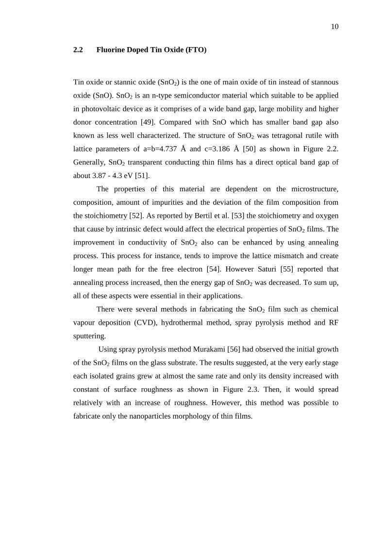
2.2 Fluorine Doped Tin Oxide (FTO)
Tin oxide or stannic oxide (SnO2) is the one of main oxide of tin instead of stannous
oxide (SnO). SnO2 is an n-type semiconductor material which suitable to be applied
in photovoltaic device as it comprises of a wide band gap, large mobility and higher
donor concentration [49]. Compared with SnO which has smaller band gap also
known as less well characterized. The structure of SnO2 was tetragonal rutile with
lattice parameters of a=b=4.737 Å and c=3.186 Å [50] as shown in Figure 2.2.
Generally, SnO2 transparent conducting thin films has a direct optical band gap of
about 3.87 - 4.3 eV [51].
The properties of this material are dependent on the microstructure,
composition, amount of impurities and the deviation of the film composition from
the stoichiometry [52]. As reported by Bertil et al. [53] the stoichiometry and oxygen
that cause by intrinsic defect would affect the electrical properties of SnO2 films. The
improvement in conductivity of SnO2 also can be enhanced by using annealing
process. This process for instance, tends to improve the lattice mismatch and create
longer mean path for the free electron [54]. However Saturi [55] reported that
annealing process increased, then the energy gap of SnO2 was decreased. To sum up,
all of these aspects were essential in their applications.
There were several methods in fabricating the SnO2 film such as chemical
vapour deposition (CVD), hydrothermal method, spray pyrolysis method and RF
sputtering.
Using spray pyrolysis method Murakami [56] had observed the initial growth
of the SnO2 films on the glass substrate. The results suggested, at the very early stage
each isolated grains grew at almost the same rate and only its density increased with
constant of surface roughness as shown in Figure 2.3. Then, it would spread
relatively with an increase of roughness. However, this method was possible to
fabricate only the nanoparticles morphology of thin films.

11
Figure 2.2: Ball and stick of the structure of SnO2
However, Liyanage et al. [57] had already improved the spray pyrolysis
deposition method (SPD) and it was able to get the FTO nanorod films with low
sheet resistance. The improved SPD was using horizontal technique of spray to keep
the low pressure during deposition process and maintaining a good percentage of
transmittance of FTO films.
Figure 2.3: The schematic drawing of the SnO2 film at early stage formed by
the SPD process [56]
The challenge for SnO2 films was having high resistivity due to the low
intrinsic carrier density and mobility. Thus, Mohalkar et al. [58] reported, for
enhancing the conductivity of SnO2, fluorine element which was from group 17 has
been introduced to be doped on host of SnO2. These non-stoichiometric films would
improve the conductivity which caused by double ionized vacancies serving as
donor. The fluorine was compatible with SnO2 as it has close ionic size as F-:1.33Å,
C
C
Oxygen
Tin
SnO2 island

12
O2-
:1.32Å, comparable bond energy with tin element (Sn) (Sn-O bond
31.05D°/kJmol-1
, Sn-F bond 26.75D°/kJ mol-1
), and low lattice coulomb forces.
Since the F- charge was half of the O
2- charge, the fluorine ions were able to occupy
the oxygen ions [59].
The grain size of FTO films was dependent on the deposition temperature,
time reaction, type of precursor and solvent that were been used [9]. Mohalkar et al.
[9] also investigated the effect of various solvents used for FTO films fabrication.
From various type of solvents used in FTO films fabrication it would able to get a
new morphology of FTO films without affecting the lattice parameter values.
However, Agness et al. [60] suggested different type of FTO film morphologies were
depend on the precursor and solvents pairs. From this pairing of precursor and
solvent, the obtained films layers have been classified into three categories which
were smooth, slightly faceted and faceted surfaces.
Another way of promoting the low resistivity was by adjusting the Sn/O ratio.
The increasing Sn/O ratio leads to create extra oxygen vacancies [61]. Then, at
certain concentration of Sn would able to get high surface area with low sheet
resistance. This concentration of precursor has important role to control the grain size
of FTO films.
On the other hand, preferred orientation of FTO film growth also influence
the electrical conductivity of FTO films as reported by Jian et al. [30]. Resistivity
increased with strengthening (110) preferred orientation and weakening (200)
preferred orientation. Then, by using hall effect measurement revealed the resistivity
was increased due to the decreasing of carrier mobility with the development of
(110) preferred orientation.
Studies on effect of annealing temperature and different type of tin precursors
were widely performed by many researchers to improve the performance of optical
properties of the thin films [55, 62]. The analyzed optical properties of FTO films
could be focused on four parameters which are refractive index, extinction
coefficient, absorption coefficient and energy gap value. As the annealing
temperature rise, the samples were demonstrated with high transmittance beyond
70% but decreased in energy gap value [55].
The FTO performance was related to their nanostructure. There were a lot of
nanostructures that could be grown such as nanoparticle [26], nanorod [27],
nanoflower [23], nanowire [28], and nanocactus [29]. There were several ways to

13
fabricate the FTO film such as spray pyrolysis [63], chemical vapour deposition [15],
rf sputtering [37] and hydrothermal method [64]. All of these nanostructures can be
classified in 0D, core-shell, 1D and 3D structures. The famous structure, used in
conventional FTO films was nanoparticle. Which offer high surface area and
maximum load of dye adsorption [65]. However, the existence of a lot of boundaries
in the FTO films layer increased the tendency of interfacial charge recombination
happened between photogenerated electrons and the positive elements in electrolyte.
Thus, an attempt from Law at el. [65] by employed 1D nanostructure could provide
direct pathway for electron transport. 1D nanostructure such as nanowire, nanorod
and nanobelt gave much faster for electron transport compared with conventional
nanoparticle films.
The recent research about nanostructure FTO films is focusing on 3D
nanostructures. 3D nanostructure provide high surface area and also has excellent
capability in achieving high light harvesting and charge transport [66]. 3D
nanostructures include of nanotetrapods, branched nanostructured from 1D structure
(nanoflower as shown in Figure 2.4, branched nanowire and dendritic nanowire),
mesh based 3D photoelectrode and spherical oxide aggregate [67].
Figure 2.4: FESEM image of SnO2 nanoflower films [68]
Instead of FTO, the antimony doped tin oxide (ATO) and indium doped tin
oxide (ITO) also have been applied as TCO materials for DSSC. As compared to
ITO and ATO, fluorine doped SnO2 has higher transparency in visible range and

14
possesses extraordinary high temperature resistance. In addition, FTO has strong
adhesion to glass and excellent chemical stability. FTO is more prefered for DSSC
due to it has low sheet resistance and high temperature stable [27, 34].
2.2.1 Precursors for FTO films preparation
Mineral salts or organometallic are made into tin precursors that which contributes in
manufacturing the DSSC. For group mineral salts, tin tetrachloride (SnCl4) was
commonly used. One of the major drawbacks in using the salt is it should be stored
in large quantities which will form HCl vapour when the SnCl4 is in contact with
ambient humidity [69] .
DBTDA is a chemical material from organometallic tin compounds that has
been used successfully to prepare high oriented SnO2 thin films on glass substrates
[70]. Organometallic compounds have been used as precursors of oxide thin films
because they are readily to decompose at or near the surface of the hot glass ribbon
[71]. The film obtained from DBTDA were polycrystalline and developed crystallites
without sharp edges provide large surface area [72]. The film crystallites do not have
sharp edges which were become an advantage for DSSC application as a transparent
and conducting electrode in a device [72].
DBTDA precursor were used in preparing thin films due to it compatible in
handling [72]. The thermal analysis for DBTDA solution shows the temperature
compatible between 320°C and 600°C, with 2.5% of the initial mass was condensed
[72]. Instead of DBTDA, there were other chemical compounds that could be used as
precursor that include tetra-n-butyltin (IV) (TBT), tri-n-butyltin acetate (TBTA),
monobutyltintrichloride (MBTC) , phenyltintrichloride (PTTC), tetravinyltin (TVT),
Tin (ll) Chloride (SnCl2), and Tin (lV) Chloride (SnCI4) [15, 70, 71, 73, 74]
Ammonium Fluoride (NH4F) was used to prepare fluorine element as it is
doped to SnO2. There were different molar ratio of precursor that have been used to
prepare F/Sn in stock solution and the most preferable were 1:2 and 1:3 [75, 76].
Several solvents were chosen to dissolve the chemical precursors which are 2
propanol, ethanol, methanol and water. These solvents should be suitable with the
type of tin precursor used, for example; DBTDA with 2-propanol [75] and
SnCl4 with acetone [57].

15
2.3 Hydrothermal method
One of the promising and cost effective methods to prepare a homogeneous thin film
is the hydrothermal method. The hydrothermal method is a liquid deposition process
which involves soft chemistry (bottom-up approach) and giving homogeneous thin
film assisted with stable temperature and pressure [25]. It also can be described as a
heterogeneous chemical reaction in a solvent above room temperature and at
pressures greater than 1 atm in a closed system [16].
In hydrothermal method, water is the reaction medium. Water is one of the
most important solvents in nature and has remarkable properties. It is a reaction
medium that operates under hydrothermal conditions which is totally different
compared to standard conditions. One of the biggest advantages of using water are
the environmental benefit, known as most cost effective solvent and acting as a
catalyst for the formation of desired materials. It is nontoxic, nonflammable,
noncarcinogenic, nonmutagenic and thermodynamically stable. Water is very volatile
as it is easier to be removed from the product.
The dispersity of particles can be improved by the hydrothermal method
without any calcination process. Besides, the hydrothermal process requires great
level of hydrothermal temperature in range of 120oC to 170
oC and consume time
around 10 hours [64]. Hydrothermal method usually have been performed under
certain temperature and reaction time as 150°C for 10 hours [25], 120-170°C for 10
hours [64] and 180°C for 72 hours [77].
The fabrication of TiO2 with high homogeneous crystalline product was
conducted using hydrothermal method by using low reaction temperature as less than
150°C. The low reaction temperature contributes on reducing in agglomeration
between particles, narrow particles size distribution, phase homogeneity, and
controlled particle morphology. It also provides a uniform composition, purity of the
product, monodispersed particles, control over the shape and size of the particles
[16].
One of the significant advantages is it has capability on hybridizing with
other process for instance [78-82]. Microwave, electrochemistry, ultrasound, mecho-
chemistry, optical radiation and hot-pressing are the alternative techniques that
concordant with hydrothermal method in enhancing reaction kinetics and increasing
ability to fabricate new materials. The hydrothermal synthesis has numerous benefits

16
over conventional and non-conventional techniques. The crucial assistance of
hydrothermal technology for nanomaterial processing is the production of particles
that are monodispersed with total control over their shape and size with highest
dispersibility of chemical homogeneity. Besides, various advanced nanomaterials
whether nanoparticles or nanocomposites comprised of metals, metal oxides,
silicates, sulphides, hydroxides, tungstates, titanates, carbon, zeolites, ceramics and
composite have been processed using hydrothermal technology [16].
The time variation of hydrothermal method was performed for the
nanoparticle ZnO growth based on increasing the reaction time from 5 to 50 hours
[16]. Byrapa & Adschiri [16] studied the effect of the formation of pure ZnO phase.
It was found that the formation of pure ZnO phase under such low temperature
condition required a minimum duration of 40 hours.
2.4 Dye-Sensitized Solar Cell
Dye-Sensitized Solar Cells (DSSC) is the third generation of photovoltaics. It was
introduced as a promising candidate to replace other type of solar cells due to cost
effectiveness and simplicity. This encouraged the academic and industrial
researchers for performing the investigations to enhance the efficiency of DSSC. As
a result, overall efficiency is as high as 15% as reported by Julian et al. [83]. These
investigations shown enhancement of the performance of each component of DSSC.
DSSC comprised of five basic components which were transparent
conducting oxide (TCO) [84], semiconductor oxide [85], dye adsorber [86],
electrolyte [87] and counter electrode [88]. The operation principles of DSSC are
divided in three stages such as absorption, separation and collection [89]. Absorption
is the process of light absorption by sensitizing dye molecule and proceeds to excited
sensitized state. Meanwhile, separation process is a process of injection of excited
electron into the conduction band of semiconductors oxide and the dye molecule
being oxidized. Third, the electron from the electrolyte is utilized to reduce the dye
molecule and make it stable again.
Figure 2.5 shows the schematic working of DSSC which is function because
of the interaction that happened between the working electrode (TCO) and counter
electrode. First, the light was transmitted through TCO into the inner part (titanium

17
oxide). TiO2 as the highway for the electron (electricity) flowing through the cell.
The nanostructures of titanium oxide films were coated by dye that was used to
convert photon into electron. Beside, between both electrodes, it has been filling with
an electrolyte to transfer electron from the counter electrode to the dye molecule. The
unstable dye after release excited electron would receive extra electron from
electrolyte to make it stable and function again. The counter electrode is generally
made of platinum receives the electron from the anode after powering whatever type
of cell then transfer to the electrolyte.
Figure 2.5: The DSSC working compenents
2.4.1 Titanium Dioxde
The central part of a DSSC device consists a thick nanoparticle film that provides a
large surface area for light-harvesting absorption molecules to attract the electron
from the excited dye. Metal oxides like titanium oxide (TiO2), zinc oxide (ZnO), tin
oxide (SnO2), niobium pentoxide (Nb2O5), tungsten trioxide (WO3), tantalum
pentoxide (Ta2O5), cadmium selenide (CdSe), cadmium tellurite (CdTe) and
cadmium sulfide (Cds) have been used as the semiconductor material in DSSC
device [90]. However, TiO2 is the most attractive semiconductor oxide in research
Gla
ss
FT
O
G
lass
Pt
Dye
TiO2
Electrolyte
Light
Counter electrode Working electrode

18
field which has been used at this part of DSSC due to its stability under extreme
condition. In DSSC, one of the TiO2 properties which lead to efficient injection of
electron is it consist of the conduction band edge that slightly lies below the excited
state energy level of many dye and it has better morphology compared to other [91].
High refractive index and dielectric constant of TiO2 also give advantage in light
absorption and preventing electron recombination in photovoltaic application [92,
93].
TiO2 consist of three crystalline phases which were rutile, anatase and
brookite. Anatase phase of TiO2 was from tetragonal structure type as shown in
Figure 2.6.
Figure 2.6: The structure bonding of rutile and anatase of TiO2 thin films [94]
This phase also has high stability at 0 K as compared to the rutile even the
energy between two phase is small [95]. Anatase TiO2 as a chemically stable
material due to high conduction band edge energy of 3.2eV and more prefer to be
used in DSSC than rutile TiO2 which has low band edge energy [96].

19
The rutile is stable in high temperature region, whereas anatase and brookite
was metastable phase and transformed to the rutile phase by annealing at high
temperature. The electron transport process in rutile was also slower when compared
to anatase due to the high packing density [97]. Beside, brookite TiO2 has larger cell
volume and more complicated than the two phase of TiO2 and it is not commonly
used in photovoltaic research [85].
There were a lot of findings which described the fabrication of anatase TiO2
pertaining to the variation of morphology such as nanoparticles, nanorod,
nanoflower, nanofiber, hollow sphere, and hollow semisphere. [98-100]. Overall,
nanoparticle TiO2 film has been considered as an ideal nanostructure semiconductor
in photovoltaic application based on improvement of the attaching geometry of the
dye on TiO2 surface due to the increment of surface quality which will led to faster
electron injection [92].
E. V. Premalal et al. [26] reported using nanoparticle of TiO2 would be able
to reach 6.48% of effiency of DSSC. It was small in grain size that consisted of high
surface area and made it possible for higher dye adsorbed at the surface of TiO2, for
boosting light harvesting and conversion of solar cell efficiency.
The fabrication of TiO2 almost similar to TCO fabrication such as
hydrothermal, spray pyrolysis deposition, electrochemical method, sol gel method
and chemical vapour deposition [101]. These methods fabricated different surface
morphology of TiO2.
2.4.2 Dyes
Dye adsorbtion was the most important part in DSSC. The function of dye adsorbed
is to convert the light (photon) and transfer the electron into conduction band in the
semiconductor material [102]. This molecular dye is chemically coated on the
surface of TiO2 before DSSC is prepared by immersing deposited TiO2 on FTO
surface in dye solution for 15 hours. The three groups of dyes are metal complex,
metal-free organic and natural dye. Among of these dyes, metal complex dyes have
high efficiency output [103].
Ruthenium (II)-polypyridyl complex was the metal complex dye group with
the most efficient dye due to its numerous advantageous features, such as good

20
N3
η=11.03%
N719
η=11.18%
Black Dye
η=11.1%
Z709
η=9.5%
absorption, long excited-state lifetime and highly efficient metal-to-ligand charge
transfer [103]. It consists of N3, N719, Z709 and black dye [87, 104, 105]. The
molecular structure of dyes are as shown in Figure 2.7 [106]. However, these metal-
complexes absorber are expensive materials that required a complicated preparation
technique.
Figure 2.7: Molecular structure of various of metal-complexes dye with efficiency
[106]
21
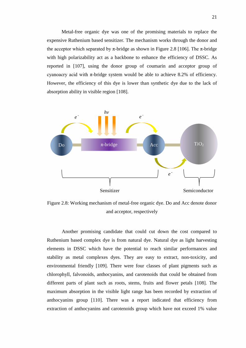
Metal-free organic dye was one of the promising materials to replace the
expensive Ruthenium based sensitizer. The mechanism works through the donor and
the acceptor which separated by π-bridge as shown in Figure 2.8 [106]. The π-bridge
with high polarizability act as a backbone to enhance the efficiency of DSSC. As
reported in [107], using the donor group of coumarin and acceptor group of
cyanoacry acid with π-bridge system would be able to achieve 8.2% of efficiency.
However, the efficiency of this dye is lower than synthetic dye due to the lack of
absorption ability in visible region [108].
Figure 2.8: Working mechanism of metal-free organic dye. Do and Acc denote donor
and acceptor, respectively
Another promising candidate that could cut down the cost compared to
Ruthenium based complex dye is from natural dye. Natural dye as light harvesting
elements in DSSC which have the potential to reach similar performances and
stability as metal complexes dyes. They are easy to extract, non-toxicity, and
environmental friendly [109]. There were four classes of plant pigments such as
chlorophyll, falvonoids, anthocyanins, and carotenoids that could be obtained from
different parts of plant such as roots, stems, fruits and flower petals [108]. The
maximum absorption in the visible light range has been recorded by extraction of
anthocyanins group [110]. There was a report indicated that efficiency from
extraction of anthocyanins and carotenoids group which have not exceed 1% value
π-bridge TiO2 Acc Do
hv e
- e -
e -
Sensitizer
Semiconductor
22
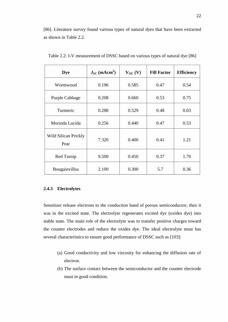
[86]. Literature survey found various types of natural dyes that have been extracted
as shown in Table 2.2.
Table 2.2: I-V measurement of DSSC based on various types of natural dye [86]
Dye JSC (mAcm2) VOC (V) Fill Factor Efficiency
Wormwood 0.196 0.585 0.47 0.54
Purple Cabbage 0.208 0.660 0.53 0.75
Turmeric 0.288 0.529 0.48 0.03
Morinda Lucida 0.256 0.440 0.47 0.53
Wild Silican Prickly
Pear 7.320 0.400 0.41 1.21
Red Turnip 9.500 0.450 0.37 1.70
Bougainvillea 2.100 0.300 5.7 0.36
2.4.3 Electrolytes
Sensitizer release electrons to the conduction band of porous semiconductor, then it
was in the excited state. The electrolyte regenerates excited dye (oxides dye) into
stable state. The main role of the electrolyte was to transfer positive charges toward
the counter electrodes and reduce the oxides dye. The ideal electrolyte must has
several characteristics to ensure good performance of DSSC such as [103]:
(a) Good conductivity and low viscosity for enhancing the diffusion rate of
electron.
(b) The surface contact between the semiconductor and the counter electrode
must in good condition.
23
(c) Not effecting the desorption of the sensitizer from oxidized surface and
the degradation of the sensitizer.
(d) It is not absorbing light in visible wavelength.
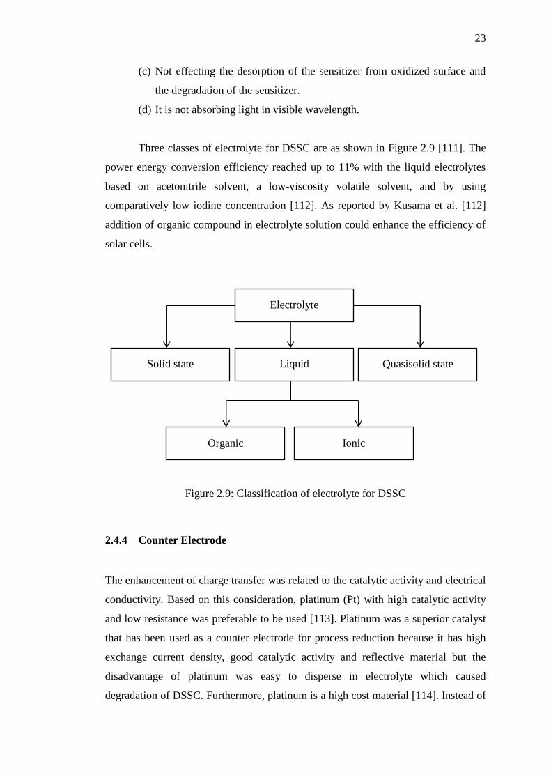
Three classes of electrolyte for DSSC are as shown in Figure 2.9 [111]. The
power energy conversion efficiency reached up to 11% with the liquid electrolytes
based on acetonitrile solvent, a low-viscosity volatile solvent, and by using
comparatively low iodine concentration [112]. As reported by Kusama et al. [112]
addition of organic compound in electrolyte solution could enhance the efficiency of
solar cells.
Figure 2.9: Classification of electrolyte for DSSC
2.4.4 Counter Electrode
The enhancement of charge transfer was related to the catalytic activity and electrical
conductivity. Based on this consideration, platinum (Pt) with high catalytic activity
and low resistance was preferable to be used [113]. Platinum was a superior catalyst
that has been used as a counter electrode for process reduction because it has high
exchange current density, good catalytic activity and reflective material but the
disadvantage of platinum was easy to disperse in electrolyte which caused
degradation of DSSC. Furthermore, platinum is a high cost material [114]. Instead of
Electrolyte
Liquid Solid state Quasisolid state
Organic Ionic

24
platinum, there were several materials like graphene and conductive polymer also
have been used as counter electrode even the efficiency for those material were much
lower compared to platinum but it would able to reduce the cost [88]. To overcome
the costing problem of platinum, Qi et al. [115] deposited polyaniline (conductive
polymer) on the stainless steel 304 (SS) for enhancing electrochemical activity. The
conductivity of the catalyst also has been improved by deposites polyaniline on the
graphitized polyimide carbon films thus exhibits the high open circuit-voltage and
efficiency of DSSC [114]. The counter electrode of DSSC should be of high
conductivity.
2.5 Summary of literature review
The hydrothermal process is an attractive method to growth the nanostructured FTO
films with high homogeneous. By forming the 3D structure of FTO films, it would
able to enhance its light scattering ability. Then, among chemical precusors, such as
SnCl4 and NH4F in molar ratio 1:3 provided high surface area and low resistivity of
thin films. This organic solvent (acetone) that has low viscosity produced a better
single crystal and increase the reaction in solution. To avoid the formation of
nanoparticle, the hydrothermal temperature must be exceeded 120°C. The irregular
nanoparticles were obtained when the reaction was carried out at low temperature
such as 120°C and below as discussed in Section 2.2.
74
REFERENCES
1. Bender, M.H., Potential conservation of biomass in the production of
synthetic organics. Resources, Conservation and Recycling, 2000. 30(1): p.
49-58.
2. Solangi, K., et al., A review on global solar energy policy. Renewable and
sustainable energy reviews, 2011. 15(4): p. 2149-2163.
3. Miles, R., Photovoltaic solar cells: Choice of materials and production
methods. Vacuum, 2006. 80(10): p. 1090-1097.
4. Jäger-Waldau, A., Photovoltaics and renewable energies in Europe.
Renewable and Sustainable Energy Reviews, 2007. 11(7): p. 1414-1437.
5. Nazeeruddin, M.K., E. Baranoff, and M. Grätzel, Dye-sensitized solar cells: a
brief overview. Solar Energy, 2011. 85(6): p. 1172-1178.
6. O’regan, B. and M. Grfitzeli, A low-cost, high-efficiency solar cell based on
dye-sensitized. Nature, 1991. 353(6346): p. 737-740.
7. Li, B., et al., Review of recent progress in solid-state dye-sensitized solar
cells. Solar Energy Materials and Solar Cells, 2006. 90(5): p. 549-573.
8. Kong, J., et al., Synthesis and properties of pure and antimony-doped tin
dioxide thin films fabricated by sol–gel technique on silicon wafer. Materials
Chemistry and Physics, 2009. 114(2): p. 854-859.
9. Moholkar, A., et al., Solvent-dependent growth of sprayed FTO thin films
with mat-like morphology. Solar Energy Materials and Solar Cells, 2008.
92(11): p. 1439-1444.
10. Ghafouri, V., M. Shariati, and A. Ebrahimzad, Photoluminescence
investigation of crystalline undoped ZnO nanostructures constructed by RF
sputtering. Scientia Iranica, 2012. 19(3): p. 934-942.
11. Yadav, A., et al., Effect of quantity of spraying solution on the properties of
spray deposited fluorine doped tin oxide thin films. Physica B: Condensed
Matter, 2009. 404(12): p. 1874-1877.
12. Chae, J., et al., Photovoltaic efficiency on dye-sensitized solar cells (DSSC)
assembled using Ga-incorporated TiO2 materials. Journal of industrial and
Engineering Chemistry, 2010. 16(6): p. 906-911.

75
13. Hossein-Babaei, F. and A. Amini, A breakthrough in gas diagnosis with a
temperature-modulated generic metal oxide gas sensor. Sensors and
Actuators B: Chemical, 2012. 166: p. 419-425.
14. Khelladi, M., et al., Early stages of cobalt electrodeposition on FTO and n-
type Si substrates in sulfate medium. Materials Chemistry and Physics, 2010.
122(2): p. 449-453.
15. Fang, T.-H. and W.-J. Chang, Effect of freon flow rate on tin oxide thin films
deposited by chemical vapor deposition. Applied surface science, 2003.
220(1): p. 175-180.
16. Byrappa, K. and T. Adschiri, Hydrothermal technology for nanotechnology.
Progress in Crystal Growth and Characterization of Materials, 2007. 53(2): p.
117-166.
17. Chen, Z., J. Lai, and C. Shek, Multifractal spectra of scanning electron
microscope images of SnO2 thin films prepared by pulsed laser deposition.
Physics Letters A, 2005. 345(1): p. 218-223.
18. Moholkar, A., et al., Effect of solvent ratio on the properties of highly
oriented sprayed fluorine-doped tin oxide thin films. Materials Letters, 2007.
61(14): p. 3030-3036.
19. Aouaj, M.A., et al., Comparative study of ITO and FTO thin films grown by
spray pyrolysis. Materials Research Bulletin, 2009. 44(7): p. 1458-1461.
20. Purushothaman, K., M. Dhanashankar, and G. Muralidharan, Preparation
and characterization of F doped SnO 2 films and electrochromic properties
of FTO/NiO films. Current Applied Physics, 2009. 9(1): p. 67-72.
21. Kaneko, S., et al., Thermal decomposition of di- n-butyltin (IV) diacetate as a
precursor for the spray pyrolysis deposition of oriented SnO2 thin films. Solid
state ionics, 2001. 141: p. 463-470.
22. Murakami, K., K. Nakajima, and S. Kaneko, Initial growth of SnO2 thin film
on the glass substrate deposited by the spray pyrolysis technique. Thin Solid
Films, 2007. 515(24): p. 8632-8636.
23. Wang, H., et al., Hierarchical growth of SnO2 nanostructured films on FTO
substrates: structural defects induced by Sn (II) self-doping and their effects
on optical and photoelectrochemical properties. Nanoscale, 2014. 6(11): p.
6084-6091.
24. Bin Ahmad, M.K. and K. Murakami, Application of Titanium Dioxide
Nanorods in DSC Using Hydrothermal Method. Advanced Materials
Research, 2011. 222: p. 24-27.

76
25. Ahmad, M.K.B., Low temperature and normal pressure growth of rutile-
phased TiO2 nanorods/nanoflowers for DSC application prepared by
hydrothermal method. Journal of Advanced Research in Physics, 2012. 3(2).
26. Premalal, E.V., et al., Development of Quality FTO Films by Spray Pyrolysis
for Dye-Sensitized Solar Cell. Electrochemistry, 2012. 80(9): p. 624-628.
27. Russo, B. and G. Cao, Fabrication and characterization of fluorine-doped
thin oxide thin films and nanorod arrays via spray pyrolysis. Applied Physics
A, 2008. 90(2): p. 311-315.
28. Johari, A., V. Rana, and M. Chander Bhatnagar, Synthesis, characterization
and ethanol sensing properties of tin oxide nanostructures. Nanomaterials
and Nanotechnology, 2011. 1(2): p. 49-54.
29. Pari, B., et al. Recent Advances in SnO2 Based Photo anode Materials for
Third Generation Photovoltaics. in Materials Science Forum. 2014. Trans
Tech Publ.
30. Wang, J.T., et al., Influence of preferred orientation on the electrical
conductivity of fluorine-doped tin oxide films. Scientific reports, 2014. 4.
31. Liu, M., et al., Hierarchical double-layered SnO2 film as a photoanode for
dye-sensitized solar cells. New Journal of Chemistry, 2013. 37(4): p. 1002-
1008.
32. Wang, Y.-F., et al., Facile fabrication of hierarchical SnO2 microspheres film
on transparent FTO glass. Inorganic chemistry, 2010. 49(4): p. 1679-1686.
33. Granqvist, C.G., Transparent conductors as solar energy materials: A
panoramic review. Solar energy materials and solar cells, 2007. 91(17): p.
1529-1598.
34. Lenzmann, F. and J. Kroon, Recent advances in dye-sensitized solar cells.
Advances in OptoElectronics, 2007. 2007.
35. Narayan, J. and B. Larson, Domain epitaxy: A unified paradigm for thin film
growth. Journal of Applied Physics, 2003. 93(1): p. 278-285.
36. Ravichandran, K. and P. Philominathan, Fabrication of antimony doped tin
oxide (ATO) films by an inexpensive, simplified spray technique using
perfume atomizer. Materials Letters, 2008. 62(17): p. 2980-2983.
37. Choi, B., et al., Optical and electrical properties of Ga2O3 doped ZnO films
prepared by rf sputtering. Thin Solid Films, 1990. 193: p. 712-720.
38. Cheng, A.-J., et al., Thermal chemical vapor deposition growth of zinc oxide
nanostructures for dye-sensitized solar cell fabrication. Applied Physics
Letters, 2008. 92(9): p. 092113.
77
39. Smith, A., et al., Relation between solution chemistry and morphology of
SnO2 based thin films deposited by a pyrosol process. Thin Solid Films, 1995.
266(1): p. 20-30.
40. Lee, S.-C., et al., Fabrication of tin oxide film by sol–gel method for
photovoltaic solar cell system. Solar energy materials and solar cells, 2003.
75(3): p. 481-487.
41. Samad, W.Z., et al., Structural, optical and electrical properties of fluorine
doped tin oxide thin films deposited using inkjet printing technique. Sains
Malaysiana, 2011. 40(3): p. 251-257.
42. Gordon, R.G., Criteria for choosing transparent conductors. MRS bulletin,
2000. 25(08): p. 52-57.
43. He, Y. and J. Kanicki, High-efficiency organic polymer light-emitting
heterostructure devices on flexible plastic substrates. Applied Physics
Letters, 2000. 76(6): p. 661-663.
44. Emons, T.T., J. Li, and L.F. Nazar, Synthesis and characterization of
mesoporous indium tin oxide possessing an electronically conductive
framework. Journal of the American Chemical Society, 2002. 124(29): p.
8516-8517.
45. Nakato, Y., K.i. Kai, and K. Kawabe, Improvement of characteristics of new-
type solar cells, having a "transparent conductor/thin Si02 layer with
ultrafine metal particles as conductive channels/n-Si" junction. Solar Energy
Materials and Solar Cells, 1995. 37(3-4): p. 323-335.
46. Hartnagel, H., et al., Semiconducting transparent thin films. 1995: Institute of
Physics Pub. Bristol, UK, Philadelphia, PA.
47. Badeker, K., Concerning the electricity conductibility and the thermoelectric
energy of several heavy metal bonds. Ann. Phys.(Leipzig), 1907. 22(4): p.
749-766.
48. Lampert, C.M., Heat mirror coatings for energy conserving windows. Solar
Energy Materials, 1981. 6(1): p. 1-41.
49. Jarzebski, Z. and J. Marton, Physical properties of SnO2 materials II.
Electrical properties. Journal of the electrochemical Society, 1976. 123(9): p.
299C-310C.
50. Dawar, A. and J. Joshi, Semiconducting transparent thin films: their
properties and applications. Journal of Materials Science, 1984. 19(1): p. 1-
23.
51. Narayanan, K., et al., Electrical characterization and type conversion in N+
irradiated CdS thin films prepared by chemical bath deposition. Materials
research bulletin, 1999. 34(10): p. 1729-1734.

78
52. Akgul, F.A., et al., Structural and electronic properties of SnO2. Journal of
Alloys and Compounds, 2013. 579: p. 50-56.
53. Stjerna, B., et al., Characterization of rf‐sputtered SnOx thin films by electron
microscopy, Hall‐effect measurement, and Mössbauer spectrometry. Journal
of applied physics, 1990. 68(12): p. 6241-6245.
54. Khan, A.F., et al., Effect of annealing on electrical resistivity of rf-magnetron
sputtered nanostructured SnO2 thin films. Applied Surface Science, 2009.
255(20): p. 8562-8565.
55. Baco, S., A. Chik, and F. Md Yassin, Study on optical properties of tin oxide
thin film at different annealing temperature. Journal of Science and
Technology, 2012. 4(1).
56. Murakami, K., K. Nakajima, and S. Kaneko, Initial growth of SnO2 thin film
on the glass substrate deposited by the spray pyrolysis technique. Thin Solid
Films, 2007. 515(24): p. 8632-8636.
57. Liyanage, D., et al., Ethylene Glycol Assisted Synthesis of Fluorine Doped
Tin Oxide Nanorods Using Improved Spray Pyrolysis Deposition Method.
Applied Physics Express, 2013. 6(8): p. 085501.
58. Moholkar, A., et al., Effect of fluorine doping on highly transparent
conductive spray deposited nanocrystalline tin oxide thin films. Applied
Surface Science, 2009. 255(23): p. 9358-9364.
59. Zhang, B., et al., The role of oxygen vacancy in fluorine-doped SnO2 films.
Physica B: Condensed Matter, 2011. 406(9): p. 1822-1826.
60. Smith, A., et al., Experimental survey of different precursor/solvent pairs for
the deposition of tin dioxide by pyrosol. Thin solid films, 1998. 315(1): p. 17-
21.
61. Bilgin, V., et al., Electrical, structural and surface properties of fluorine
doped tin oxide films. Applied Surface Science, 2010. 256(22): p. 6586-6591.
62. Dien, E., J. Laurent, and A. Smith, Comparison of optical and electrical
characteristics of SnO2 based thin films deposited by pyrosol from different
tin precursors. Journal of the European Ceramic Society, 1999. 19(6): p. 787-
789.
63. Kaneko, S., et al., Thermal decomposition of di-n-butyltin(IV) diacetate as a
precursor for the spray pyrolysis deposition of oriented SnO2 thin films. Solid
State Ionics, 2001. 141–142(0): p. 463-470.
64. Zhang, J. and L. Gao, Synthesis and characterization of antimony-doped tin
oxide (ATO) nanoparticles by a new hydrothermal method. Materials
chemistry and physics, 2004. 87(1): p. 10-13.

79
65. Law, M., et al., Nanowire dye-sensitized solar cells. Nature materials, 2005.
4(6): p. 455-459.
66. Chen, G.-Y., M.-W. Lee, and G.-J. Wang, Fabrication of dye-sensitized solar
cells with a 3D nanostructured electrode. International Journal of
Photoenergy, 2010. 2010.
67. Zhang, Q. and G. Cao, Nanostructured photoelectrodes for dye-sensitized
solar cells. Nano Today, 2011. 6(1): p. 91-109.
68. Wang, Y.-L., et al., Hydrothermal preparation and photoelectrochemical
performance of size-controlled SnO2 nanorod arrays. CrystEngComm, 2010.
12(12): p. 4024-4027.
69. Laurent, J.-M., et al., Morphology and physical properties of SnO2 based thin
films deposited by the pyrosol process from dibutyltindiacetate. Thin Solid
Films, 1997. 292(1): p. 145-149.
70. Murakami, K., I. Yagi, and S. Kaneko, Oriented growth of tin oxide thin films
on glass substrates by spray pyrolysis of organotin compounds. Journal of the
American Ceramic Society, 1996. 79(10): p. 2557-2562.
71. Zhao, H., et al., Effects of water on the structure and properties of F-doped
SnO2 films. Materials Letters, 2008. 62(8): p. 1294-1296.
72. Laurent, J.-M., et al., Morphology and physical properties of SnO2 based thin
films deposited by the pyrosol process from dibutyltindiacetate. Thin Solid
Films, 1997. 292(1): p. 145-149.
73. Patil, P., et al., Properties of spray deposited tin oxide thin films derived from
tri-n-butyltin acetate. Thin Solid Films, 2003. 437(1): p. 34-44.
74. Fukano, T. and T. Motohiro, Low-temperature growth of highly crystallized
transparent conductive fluorine-doped tin oxide films by intermittent spray
pyrolysis deposition. Solar energy materials and solar cells, 2004. 82(4): p.
567-575.
75. Premalal, E., et al., Preparation of high quality spray-deposited fluorine-
doped tin oxide thin films using dilute di (n-butyl) tin (iv) diacetate precursor
solutions. Thin Solid Films, 2012. 520(22): p. 6813-6817.
76. Moholkar, A., et al., Effect of concentration of SnCl4 on sprayed fluorine
doped tin oxide thin films. Journal of alloys and compounds, 2008. 455(1): p.
440-446.
77. Wu, S., et al., Preparation, characterization and electrical properties of
fluorine-doped tin dioxide nanocrystals. Journal of colloid and interface
science, 2010. 346(1): p. 12-16.

80
78. Byrappa, K. and M. Yoshimura, Handbook of hydrothermal technology.
2001: William Andrew.
79. Morey, G.W. and P. Niggli, The hydrothermal formation of silicates, a
review. Journal of the American Chemical Society, 1913. 35(9): p. 1086-
1130.
80. Lobachev, A., Crystallization processes under hydrothermal conditions.
1973.
81. Byrappa, K., Hydrothermal growth of crystals. International School on
Crystal Growth of Technologically Important Electronic Materials, 2003: p.
271.
82. Yoshimura, M. and H. Suda, Hydrothermal processing of hydroxyapatite:
past, present, and future. Hydroxyapatite and Related Compounds. Boca
Raton (EE. UU.): CRC Press Inc, 1994: p. 45-72.
83. Burschka, J., et al., Sequential deposition as a route to high-performance
perovskite-sensitized solar cells. Nature, 2013. 499(7458): p. 316-319.
84. Napi, M., et al. Surface Morphology and Electrical Properties of FTO
(Fluorine Doped Tin Oxide) with Different Precursor Solution for
Transparent Conducting Oxide. in Applied Mechanics and Materials. 2015.
Trans Tech Publ.
85. Thompson, T.L. and J.T. Yates, Surface science studies of the
photoactivation of TiO2 new photochemical processes. Chemical Reviews,
2006. 106(10): p. 4428-4453.
86. Calogero, G., et al., Efficient dye-sensitized solar cells using red turnip and
purple wild sicilian prickly pear fruits. International journal of molecular
sciences, 2010. 11(1): p. 254-267.
87. Chiba, Y., et al., Dye-sensitized solar cells with conversion efficiency of
11.1%. Japanese Journal of Applied Physics, 2006. 45(7L): p. L638.
88. Andrade, L., H.A. Ribeiro, and A. Mendes, Dye–Sensitized Solar Cells: An
Overview. Encyclopedia of Inorganic and Bioinorganic Chemistry, 2011.
89. Pari, B., et al. Recent Advances in SnO2 Based Photo anode Materials for
Third Generation Photovoltaics. in Materials Science Forum. 2014. Trans
Tech Publ.
90. Suhaimi, S., et al., Materials for Enhanced Dye-sensitized Solar Cell
Performance: Electrochemical Application. Int. J. Electrochem. Sci, 2015.
10: p. 2859-2871.
91. O'regan, B. and M. Grätzel, A low-cost, high-efficiency solar cell based on
dye-sensitized colloidal TiO2 films. nature, 1991. 353(6346): p. 737-740.

81
92. Gupta, S.M. and M. Tripathi, A review of TiO2 nanoparticles. Chinese
Science Bulletin, 2011. 56(16): p. 1639-1657.
93. Kay, A. and M. Grätzel, Low cost photovoltaic modules based on dye
sensitized nanocrystalline titanium dioxide and carbon powder. Solar Energy
Materials and Solar Cells, 1996. 44(1): p. 99-117.
94. Diebold, U., The surface science of titanium dioxide. Surface science reports,
2003. 48(5): p. 53-229.
95. Muscat, J., V. Swamy, and N.M. Harrison, First-principles calculations of
the phase stability of TiO2. Physical Review B, 2002. 65(22): p. 224112.
96. Wunderlich, W., et al., Electronic Properties Of Nano-Porous TiO2 and ZnO
Thin Films- Comparison Of Simulations And Experiments. Journal of
Ceramic Processing & Research, 2004. 5(4): p. 343-354.
97. Duong, T.-T., et al., Enhancing the efficiency of dye sensitized solar cells
with an SnO2 blocking layer grown by nanocluster deposition. Journal of
Alloys and Compounds, 2013. 561: p. 206-210.
98. Song, M.Y., et al., Electrospun TiO2 electrodes for dye-sensitized solar cells.
Nanotechnology, 2004. 15(12): p. 1861.
99. Adachi, M., et al., Highly efficient dye-sensitized solar cells with a titania
thin-film electrode composed of a network structure of single-crystal-like
TiO2 nanowires made by the “oriented attachment” mechanism. Journal of
the American Chemical Society, 2004. 126(45): p. 14943-14949.
100. Yang, S.-C., et al., Hollow TiO2 hemispheres obtained by colloidal
templating for application in dye-sensitized solar cells. Advanced Materials-
Deerfield Beach Then Weinheim, 2008. 20(5): p. 1059.
101. Shalini, S., et al., Review on natural dye sensitized solar cells: Operation,
materials and methods. Renewable and Sustainable Energy Reviews, 2015.
51: p. 1306-1325.
102. Kalyanasundaram, K. and M. Grätzel, Efficient dye-sensitized solar cells for
direct conversion of sunlight to electricity. Material Matters, 2009. 4(4): p.
88-90.
103. Mehmood, U., et al., Recent Advances in Dye Sensitized Solar Cells.
Advances in Materials Science and Engineering, 2014. 2014.
104. Grätzel, M., Conversion of sunlight to electric power by nanocrystalline dye-
sensitized solar cells. Journal of Photochemistry and Photobiology A:
Chemistry, 2004. 164(1): p. 3-14.

82
105. Nazeeruddin, M.K., et al., A swift dye uptake procedure for dye sensitized
solar cells. Chemical Communications, 2003(12): p. 1456-1457.
106. Mishra, A., M.K. Fischer, and P. Bäuerle, Metal‐free organic dyes for dye‐sensitized solar cells: From structure: Property relationships to design rules.
Angewandte Chemie International Edition, 2009. 48(14): p. 2474-2499.
107. Hara, K., et al., Oligothiophene-containing coumarin dyes for efficient dye-
sensitized solar cells. The Journal of Physical Chemistry B, 2005. 109(32): p.
15476-15482.
108. Hara, K., et al., Dye-sensitized nanocrystalline TiO2 solar cells based on
novel coumarin dyes. Solar Energy materials and Solar cells, 2003. 77(1): p.
89-103.
109. Hug, H., et al., Biophotovoltaics: natural pigments in dye-sensitized solar
cells. Applied Energy, 2014. 115: p. 216-225.
110. Narayan, M.R., Review: dye sensitized solar cells based on natural
photosensitizers. Renewable and Sustainable Energy Reviews, 2012. 16(1): p.
208-215.
111. Nogueira, A., C. Longo, and M.-A. De Paoli, Polymers in dye sensitized solar
cells: overview and perspectives. Coordination Chemistry Reviews, 2004.
248(13): p. 1455-1468.
112. Kusama, H. and H. Arakawa, Influence of pyrazole derivatives in I−/I3
− redox
electrolyte solution on Ru (II)-dye-sensitized TiO2 solar cell performance.
Solar energy materials and solar cells, 2005. 85(3): p. 333-344.
113. Li, P., et al., High-performance and low platinum loading Pt/Carbon black
counter electrode for dye-sensitized solar cells. Solar Energy, 2009. 83(6): p.
845-849.
114. Chen, J., et al., Polyaniline nanofiber/carbon film as flexible counter
electrodes in platinum-free dye-sensitized solar cells. Electrochimica Acta,
2011. 56(12): p. 4624-4630.
115. Qin, Q., J. Tao, and Y. Yang, Preparation and characterization of
polyaniline film on stainless steel by electrochemical polymerization as a
counter electrode of DSSC. Synthetic Metals, 2010. 160(11): p. 1167-1172.
116. SANDBORG, A., Energy Dispersive X-Ray Spectrometry--Eds
Instrumentation & Signal Detection, 2015, EDAX Training Course. sl:
EDAX INTERNATIONAL, INC.
117. Zhang, X.-t., et al., Al2O 3 coated nanoporous TiO2 electrode for solid-state
dye-sensitized solar cell. Solar energy materials and solar cells, 2003. 80(3):
p. 315-326.

83
118. Agashe, C. and S. Major, Effect of heavy doping in SnO2: F films. Journal of
materials science, 1996. 31(11): p. 2965-2969.
119. Wang, H., et al., Hydrothermal synthesis of hierarchical SnO2 microspheres
for gas sensing and lithium-ion batteries applications: Fluoride-mediated
formation of solid and hollow structures. Journal of Materials Chemistry,
2012. 22(5): p. 2140-2148.
120. Guneri, E., et al., Effect of deposition time on structural, electrical, and
optical properties of SnS thin films deposited by chemical bath deposition.
Applied Surface Science, 2010. 257(4): p. 1189-1195.
121. Huang, X., et al., Preparation of fluorine-doped tin oxide (SnO2: F) film on
polyethylene terephthalate (PET) substrate. Materials Letters, 2010. 64(15):
p. 1701-1703.
122. Martinez, A., et al., Physicochemical characteristics of fluorine doped tin
oxide films. Journal of Physics D: Applied Physics, 2006. 39(23): p. 5091.
123. Batzill, M. and U. Diebold, The surface and materials science of tin oxide.
Progress in surface science, 2005. 79(2): p. 47-154.
124. Xie, J., et al., Morphology control of ZnO particles via aqueous solution
route at low temperature. Materials Chemistry and Physics, 2009. 114(2): p.
943-947.
125. Huang, R., et al., Effect of hydrothermal temperature on structure and
photochromic properties of WO3 powder. Advanced Powder Technology,
2012. 23(2): p. 211-214.
126. Khuc, Q.T., et al., The influence of hydrothermal temperature on SnO2
nanorod formation. Advances in Natural Sciences: Nanoscience and
Nanotechnology, 2010. 1(2): p. 025010.
127. Apetz, R. and M.P. Bruggen, Transparent Alumina: A Light‐Scattering
Model. Journal of the American Ceramic Society, 2003. 86(3): p. 480-486.
128. Koo, H.J., et al., Nano‐embossed Hollow Spherical TiO2 as Bifunctional
Material for High‐Efficiency Dye‐Sensitized Solar Cells. Advanced Materials,
2008. 20(1): p. 195-199.
129. Zhang, Q., et al., Aggregation of ZnO Nanocrystallites for High Conversion
Efficiency in Dye‐Sensitized Solar Cells. Angewandte Chemie, 2008.
120(13): p. 2436-2440.
130. Ramasamy, E., et al., Nanocarbon counterelectrode for dye sensitized solar
cells. Applied Physics Letters, 2007. 90(17): p. 173103.

84
131. Qian, J., et al., TiO2 coated multilayered SnO2 hollow microspheres for dye‐sensitized solar cells. Advanced Materials, 2009. 21(36): p. 3663-3667.
132. Kim, Y.J., et al., Formation of Highly Efficient Dye‐Sensitized Solar Cells by
Hierarchical Pore Generation with Nanoporous TiO2 Spheres. Advanced
Materials, 2009. 21(36): p. 3668-3673.
133. Zhou, Y. and M. Antonietti, Synthesis of very small TiO2 nanocrystals in a
room-temperature ionic liquid and their self-assembly toward mesoporous
spherical aggregates. Journal of the American Chemical Society, 2003.
125(49): p. 14960-14961.