fabrication and characterization of 1-d alumina (al o
TRANSCRIPT

BULLETIN OF THE POLISH ACADEMY OF SCIENCESTECHNICAL SCIENCESVol. 55, No. 2, 2007
Fabrication and characterization of 1-D alumina (Al2O3)nanofibers in an electric field
A.-M. AZAD∗, M. NOIBI, and M. RAMACHANDRANDepartment of Chemical and Environmental Engineering, The University of Toledo, 3052 Nitschke Hall, 2801 W. Bancroft St.,
Toledo, OH 43606-3390, USA
Abstract. The technique of electrospinning was employed to fabricate uniform one-dimensional inorganic-organic compositenanofibers at room temperature from a solution containing equal volumes of aluminum 2, 4-pentanedionate in acetone andpolyvinylpyrrolidone in ethanol. Upon firing and sintering under carefully pre-selected time-temperature profiles (heating rate,temperature and soak time), high-purity and crystalline alumina nanofibers retaining the original morphological features presentin the as-spun composite (cermer) fibers were obtained. Tools such as laser Raman spectroscopy, scanning and transmissionelectron microscopy together with energy dispersive spectroscopy and selected area electron diffraction were employed to followthe systematic evolution of the ceramic phase and its morphological features in the as-spun and the fired fibers. X-ray diffractionwas used to identify the crystalline fate of the final product.
Key words: electrospinning, alumina nanofibers, electron microscopy, Raman spectroscopy, X-ray diffraction.
1. Introduction
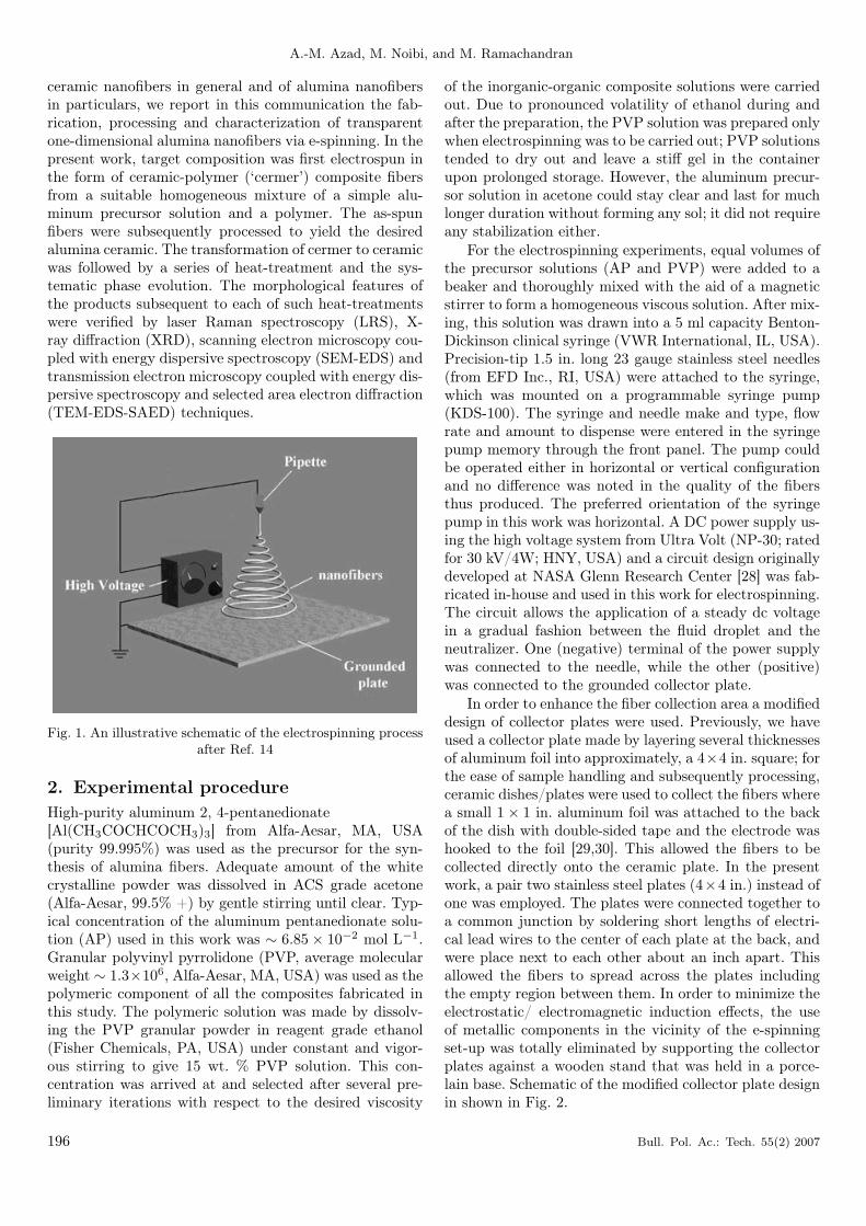
Recently, for the fabrication of nanostructures bottom-upapproaches have received increasing attention and elec-trospinning (e-spinning) is one of them. The technique ofe-spinning was discovered nearly 100 years ago [1] andhas been successfully used for making polymer nanofibersfor the past several decades [2–12]; the first US patentwas issued in 1934 [13]. As is well known, the techniqueof electrospinning uses external electrical forces to pro-duce novel polymeric fibers of diameters in the range of3–1000 nm, depending upon the strength of the appliedvoltage between a drop of the precursor solution (or melt)and the collecting surface. Electrospinning occurs whenthe electrical forces at the surface of the drop overcomethe surface tension. When this happens, the solution ormelt is ejected as an electrically charged jet and shootstowards the oppositely charged electrode. Upon reachingthe collector surface, it gets neutralized and collects as drynanofibers. Figure 1 shows the basic set-up and workingprinciple of this technique [14].
The possibility of extending the concept to ceramicsystems has opened a new era in nanoscale research dur-ing the past couple of years. It is possible to synthe-size these one-dimensional nanofibers in pure form or assuitable ceramic-polymer composites. It is also envisagedthat by controlling the jet orifice, one can control the di-ameter of the resulting nanofibrillar structures, therebymodifying their key properties such as structure, elastic-ity, strength and resistance to fracture, thermal and elec-trical conductivity, and optical characteristics, etc. [15–17]. Thus, it has seen a revival and its adaptation to
ceramic systems. Several papers and patents have sincebeen published and issued [16–23]. Sigmund et al. have re-cently reviewed the processing and structure relationshipsin the electrospun ceramic fibers [24]. Potential applica-tion of this technology includes biological membranes forimmobilized enzymes and catalysts, artificial blood ves-sels, anti-septic wound dressing materials, aerosol filters,to name a few. The possibility of extending the conceptto ceramic systems would open a new era in nanoscaleresearch. Examples of such novel nanocomposites wouldbe: piezoelectric-polymers, magnetic-polymers or opticalpolymers, depending upon the choice of the ceramic com-ponent of the composite. Furthermore, by establishingadequate processing protocols, it is possible to form ananofiber composite of two ceramics in a core-shell con-centric design [9,25]. Such nanocomposites would findimmense applications as lightweight, inexpensive, high-strength structural as well as multifunctional components.By using an orthogonal set up (electrospinning simultane-ously at right-angles), a matty design of a given ceramicor two ceramic nanofibers can also be fabricated; a pos-sible application of such a design would be the clothingmembranes for protection against fire, battlefield threatand environmental hazards.
Alumina (Al2O3) is a well-known material amongfunctional ceramics – in the area of catalysis, microelec-tronics and optics [26–27] – both in pure form as well asin combination with others. Its applications range frompure and transparent thin films as optical windows to par-ticulates, platelets and fibers as strengthening reinforce-ments in light-weight ultra-strong metal matrix compos-ites. Giving due cognizance to the potential application of
∗e-mail: [email protected]
195
A.-M. Azad, M. Noibi, and M. Ramachandran
ceramic nanofibers in general and of alumina nanofibersin particulars, we report in this communication the fab-rication, processing and characterization of transparentone-dimensional alumina nanofibers via e-spinning. In thepresent work, target composition was first electrospun inthe form of ceramic-polymer (‘cermer’) composite fibersfrom a suitable homogeneous mixture of a simple alu-minum precursor solution and a polymer. The as-spunfibers were subsequently processed to yield the desiredalumina ceramic. The transformation of cermer to ceramicwas followed by a series of heat-treatment and the sys-tematic phase evolution. The morphological features ofthe products subsequent to each of such heat-treatmentswere verified by laser Raman spectroscopy (LRS), X-ray diffraction (XRD), scanning electron microscopy cou-pled with energy dispersive spectroscopy (SEM-EDS) andtransmission electron microscopy coupled with energy dis-persive spectroscopy and selected area electron diffraction(TEM-EDS-SAED) techniques.
Fig. 1. An illustrative schematic of the electrospinning processafter Ref. 14
2. Experimental procedureHigh-purity aluminum 2, 4-pentanedionate[Al(CH3COCHCOCH3)3] from Alfa-Aesar, MA, USA(purity 99.995%) was used as the precursor for the syn-thesis of alumina fibers. Adequate amount of the whitecrystalline powder was dissolved in ACS grade acetone(Alfa-Aesar, 99.5% +) by gentle stirring until clear. Typ-ical concentration of the aluminum pentanedionate solu-tion (AP) used in this work was ∼ 6.85 × 10⁻² mol L−1.Granular polyvinyl pyrrolidone (PVP, average molecularweight ∼ 1.3×10⁶, Alfa-Aesar, MA, USA) was used as thepolymeric component of all the composites fabricated inthis study. The polymeric solution was made by dissolv-ing the PVP granular powder in reagent grade ethanol(Fisher Chemicals, PA, USA) under constant and vigor-ous stirring to give 15 wt. % PVP solution. This con-centration was arrived at and selected after several pre-liminary iterations with respect to the desired viscosity
of the inorganic-organic composite solutions were carriedout. Due to pronounced volatility of ethanol during andafter the preparation, the PVP solution was prepared onlywhen electrospinning was to be carried out; PVP solutionstended to dry out and leave a stiff gel in the containerupon prolonged storage. However, the aluminum precur-sor solution in acetone could stay clear and last for muchlonger duration without forming any sol; it did not requireany stabilization either.
For the electrospinning experiments, equal volumes ofthe precursor solutions (AP and PVP) were added to abeaker and thoroughly mixed with the aid of a magneticstirrer to form a homogeneous viscous solution. After mix-ing, this solution was drawn into a 5 ml capacity Benton-Dickinson clinical syringe (VWR International, IL, USA).Precision-tip 1.5 in. long 23 gauge stainless steel needles(from EFD Inc., RI, USA) were attached to the syringe,which was mounted on a programmable syringe pump(KDS-100). The syringe and needle make and type, flowrate and amount to dispense were entered in the syringepump memory through the front panel. The pump couldbe operated either in horizontal or vertical configurationand no difference was noted in the quality of the fibersthus produced. The preferred orientation of the syringepump in this work was horizontal. A DC power supply us-ing the high voltage system from Ultra Volt (NP-30; ratedfor 30 kV/4W; HNY, USA) and a circuit design originallydeveloped at NASA Glenn Research Center [28] was fab-ricated in-house and used in this work for electrospinning.The circuit allows the application of a steady dc voltagein a gradual fashion between the fluid droplet and theneutralizer. One (negative) terminal of the power supplywas connected to the needle, while the other (positive)was connected to the grounded collector plate.
In order to enhance the fiber collection area a modifieddesign of collector plates were used. Previously, we haveused a collector plate made by layering several thicknessesof aluminum foil into approximately, a 4×4 in. square; forthe ease of sample handling and subsequently processing,ceramic dishes/plates were used to collect the fibers wherea small 1 × 1 in. aluminum foil was attached to the backof the dish with double-sided tape and the electrode washooked to the foil [29,30]. This allowed the fibers to becollected directly onto the ceramic plate. In the presentwork, a pair two stainless steel plates (4×4 in.) instead ofone was employed. The plates were connected together toa common junction by soldering short lengths of electri-cal lead wires to the center of each plate at the back, andwere place next to each other about an inch apart. Thisallowed the fibers to spread across the plates includingthe empty region between them. In order to minimize theelectrostatic/ electromagnetic induction effects, the useof metallic components in the vicinity of the e-spinningset-up was totally eliminated by supporting the collectorplates against a wooden stand that was held in a porce-lain base. Schematic of the modified collector plate designin shown in Fig. 2.
196 Bull. Pol. Ac.: Tech. 55(2) 2007

Fabrication and characterization of 1-D alumina (Al2O3) nanofibers in an electric field
Fig. 2. A modified system of fiber collection adopted in thiswork
Using the power supply, a voltage of 7–9 kV was ap-plied between the needle and the collectors in order toinitiate the e-spinning. After the voltage was turned on,the syringe pump was started. The voltage was tweakedprecisely by adjusting the voltage knob in small steps inboth the directions until the fibers began to form steadilyand collect on the plates placed about 4 in. away fromthe tip of the needle. A flow rate of 0.03 ml/h was chosenand the cermer fibers were spun continuously with shortintermittent interruptions (lasting about 5 sec.) of the runfor the cleaning of clogged needle-tip from time to time.The process variables were optimized after considerablesimulation and several preliminary experiments. On anaverage, it took about 800h to spin ∼ 10 ml of the com-posite solution. Under optimized processing conditions,continuous and long fibers spun uniformly and collectedin the form of non-woven mat, which increased in volumewith time.
After spinning was complete, small amounts of the as-spun composite fibers were used for characterization byRaman spectroscopy and scanning electron microscopy.The remaining fibers were collected on zirconia cruciblesand fired at 1000, 1300 and 1500◦C for 1h in two stages.In order to retain these fibrillar artifacts in the processedceramic as well, firing in a carefully selected heating andcooling profile is warranted. Various batches of dry cer-mer fibers were first heated slowly at a ramp rate of1/2◦ min.−1 up to 500◦C (soak time, 1h) followed by asecond firing up to 1000, 1300 or 1500◦C for 1h at thesame heating rate of 1/2◦ min.−1. The second stage heat-treatment is meant to facilitate crystallization and consol-idation of the desired ceramic phase. The small heatingrates were chosen so as to ensure the removal of organiccomponents without destroying the nanofibrillar morpho-logical features in the end product and also to avoid thedisintegration of the alumina fibers; it is well known thatalumina exhibits rather poor thermal shock resistance,even in bulk. Fired samples were characterized by a hostof analytical techniques, such as, Raman spectroscopy,X-ray diffraction, scanning and transmission electron mi-croscopy, energy dispersive spectroscopy and selected areadiffraction.
3. Results and discussion
Figure 3 shows Al2O3-PVP composite fibers formed inreal-time on and between the twin collector plates witha taut cloth-like distribution, which could be peeled offrather easily for further processing, while Fig. 4 showsthe scanning electron micrographs (acquired on a PhilipsXL30 FEG SEM) of the same. Individual fibers possess-ing uniform morphological features with large aspect ratiocan be easily seen. Directionality endowed to the as-spunfibers under the influence of the imposed electric field isalso evident.
Fig. 3. Collection of the wafer-like non-woven mat of the as-spun Al2O3-PVP composite
Fig. 4. Morphological features of the as-spun AP-PVP fibers
The SEM pictures of the composite fibers fired instatic air environment for 1h each at 1000 and 1300◦Care shown in Figure 5 and 6, respectively. As can be read-ily seen, the fibrillar attributes observed in the as-spuncomposite are fully retained in the fired samples, with theexpected and considerable decrease in the fiber diameter.
Bull. Pol. Ac.: Tech. 55(2) 2007 197
A.-M. Azad, M. Noibi, and M. Ramachandran
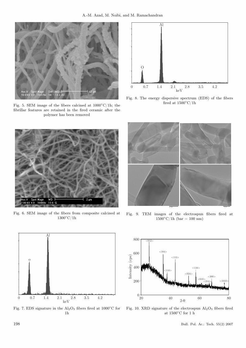
Fig. 5. SEM image of the fibers calcined at 1000◦C/1h; thefibrillar features are retained in the fired ceramic after the
polymer has been removed
Fig. 6. SEM image of the fibers from composite calcined at1300◦C/1h
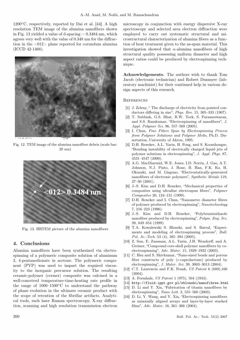
Fig. 7. EDS signature in the Al2O3 fibers fired at 1000◦C for1h
Fig. 8. The energy dispersive spectrum (EDS) of the fibersfired at 1500◦C/1h
Fig. 9. TEM images of the electrospun fibers fired at1500◦C/1h (bar = 100 nm)
Fig. 10. XRD signature of the electrospun Al2O3 fibers firedat 1500◦C for 1 h
198 Bull. Pol. Ac.: Tech. 55(2) 2007

Fabrication and characterization of 1-D alumina (Al2O3) nanofibers in an electric field
Fig. 11. SAED pattern of the electrospun fibers fired at 1500◦Cfor 1 h
It is also interesting to note that as the calcinationtemperature increased further, grain coalescence, inter-granular connectivity and interfibrillar cross-linking be-came increasing evident. The energy dispersive spectra ac-quired on the fibers fired at 1000◦C for 1h, shown in Fig. 7indicate the presence of aluminum and oxygen alone. Theelemental quantification (within the ( 3% permissible er-ror limit) performed by the standardless ZAF correctionmethod yields the average aluminum concentration to be43.76 wt. % (31.57 at. %) which is rather in large devia-tion from 52.93 wt. %, had the product been stoichiomet-ric alumina (Al2O3) after this heat-treatment.
It is well known that the formation and crystalliza-tion of aluminum oxide goes through a number of phasetransition schemes, one of which involves the formation ofboehmite phase, AlO(OH), particularly in the case of alu-minum hydroxide or other complex precursors. The mostaccepted pathway of dehydration followed by several se-quential transitions from a polymeric, partially disorderedstate to the crystalline α-alumina via a number of inter-mediates can be represented as [31,32]:AlO(OH) (Boehmite) → γ-Al2O3 → δ-Al2O3 → θ-Al2O3
→ α-Al2O3.The theoretical weight fraction of aluminum in
boehmite is 45%, which is in good agreement with that ob-tained from the EDS analysis of the fibers fired at 1000◦C.Thus, it is likely that at this stage, the aluminum pre-cursor in the AP-PVP composite is reduced to boehmiteinstead of the target phase, alumina.
On the other hand, the quantitative analysis of theEDS spectrum (shown in Fig. 8) of the fibers obtainedafter they were calcined at 1500◦C for 1h yielded a valueof 54.84 wt. % aluminum in the calcined fibers, therebyconfirming that fibers are indeed those of alumina.
At this juncture, it is natural to speculate the pres-ence of carbon as an impurity in the fired samples re-sulting from the degradation and carburization of PVPupon heat-treatment of the as-spun composite fibers. Itis, however, rather hard to detect carbon if formed, byXRD, especially if it is present as trace impurity, but it ispossible to identify it easily by Raman spectroscopy sincecarbon is strongly Raman active. The distinct D and Gpeaks of carbon are observed around 1332–1350 and 1560–1600 cm−1, respectively [33–35]. The laser Raman spec-troscopy (LSR) data collected in the wave numbers rangeof 1200 to 2000 cm−1 (LabRam, Jobin-Yvon Horiba Inc.,laser excitation wavelength = 633 nm) showed no Ramansignal characteristic of D or G peak for carbon in thespectrum collected on the fibers fired at 1500◦C for 1h.Thus, the carbon from the polymeric component as wellas from the organic precursor of aluminum is completelyeliminated during the heat-treatment adopted here. Fur-thermore, the Raman peaks of the fired fibers were foundto be identical to those obtained on commercial α-aluminapowder, and are well documented for the Al-O bonds inalumina specimen [37].
The transmission electron micrographs of the compos-ite fired at 1500◦C are shown in Fig. 9; on average thefibers are ∼ 150 nm across the diameter and are transpar-ent. The quantitative analysis of the TEM-EDS spectrumof these fibers yielded a value of 56.4 wt.% aluminum inthe calcined fibers, thereby confirming that fibers are in-deed those of alumina.
Figure 10 shows the room temperature XRD pattern(Philips, PW 3050/60 X’pert Pro) of the fibers fired at1500◦C, which conforms to that of α-alumina (ICDD card# 74-0323). The selected area electron diffraction (SAED)pattern shown in Fig. 11 also confirmed the evolved phaseto be α-alumina.
The XRD data was also used to compute the approxi-mate crystallite size in the using Scherrer equation [38–40]that relates the full-width of the most intense peak at thecenter of the maximum height (FWHM) and the diffrac-tion angle as follows:
s =Kλ
β1/2 cos θ
where s is the crystallite size (Å), λ, the wave length of theincident radiations, β1/2, the FWHM of the Bragg peak, θis the Bragg angle of diffraction of the selected peak; K isthe Scherrer constant whose value varies between 0.9 and1.2 depending upon the shape of the particle under con-sideration (spherical, cubic or otherwise) [41–43]; we useda value of 0.94 for K [36] in the Scherrer equation for thetwo most intense diffractions, viz., <104> and <113>,which yielded 2.5 nm as an average value for the crys-tallite size in the alumina fibers calcined at 1500◦C. TheTEM picture of the debris of the same fibers (Fig. 12)shows alumina grains to be in the size range of 3–5 nm;this is in contrast to the grain size up to 60 nm and 110 nmin the alumina-borate fibers calcined for 2h at 1000 and
Bull. Pol. Ac.: Tech. 55(2) 2007 199
A.-M. Azad, M. Noibi, and M. Ramachandran
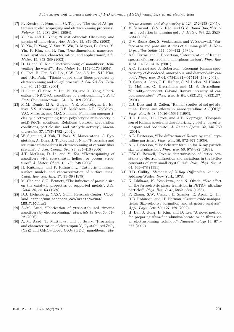
1200◦C, respectively, reported by Dai et al. [44]. A highresolution TEM image of the alumina nanofibers shownin Fig. 13 yielded a value of d-spacing = 0.3484 nm, whichagrees very well with the value of 0.348 nm for the diffrac-tion in the <012> plane reported for corundum alumina(ICCD 42-1468).
Fig. 12. TEM image of the alumina nanofiber debris (scale bar:20 nm)
Fig. 13. HRTEM picture of the alumina nanofibers
4. ConclusionsAlumina nanofibers have been synthesized via electro-spinning of a polymeric composite solution of aluminum2, 4-pentanedionate in acetone. The polymeric compo-nent (PVP) was used to impart the required viscos-ity to the inorganic precursor solution. The resultingceramic-polymer (cermer) composite was calcined in awell-conceived temperature-time-heating rate profile inthe range of 1000–1500◦C to understand the pathwayof phase evolution in the ultimate ceramic product withthe scope of retention of the fibrillar artifacts. Analyti-cal tools, such laser Raman spectroscopy, X-ray diffrac-tion, scanning and high resolution transmission electron
microscopy in conjunction with energy dispersive X-rayspectroscopy and selected area electron diffraction wereemployed to carry out systematic structural and mi-crostructural characterization of alumina fibers as a func-tion of heat treatment given to the as-spun material. Thisinvestigation showed that α-alumina nanofibers of highstructural quality possessing uniform diameter and highaspect ratios could be produced by electrospinning tech-nique.
Acknowledgements. The authors wish to thank TomJacob (electronic technician) and Robert Dunmyer (lab-oratory machinist) for their continued help in various de-sign aspects of this research.
References
[1] J. Zeleny, “ The discharge of electricity from pointed con-ductors differing in size”, Phys. Rev. 15, 305–333 (1907).
[2] T. Subbiah, G.S. Bhat, R.W. Tock, S. Parameswaran,and S.S. Ramkumar, “Electrospinning of nanofibers”, J.Appl. Polymer Sci. 96, 557–569 (2005).
[3] I. Chun, Fine Fibers Spun by Electrospinning Processfrom Polymer Solutions and Polymer Melts, Ph.D. Dis-sertation, University of Akron, 1995.
[4] D.H. Reneker, A.L. Yarin, H. Fong, and S. Koomhongse,“Bending instability of electrically charged liquid jets ofpolymer solutions in electrospinning”, J. Appl. Phys. 87,4531–4547 (2000).
[5] A.G. MacDiarmid, W.E. Jones, I.D. Norris, J. Gao, A.T.Johnson, N.J. Pinto, J. Hone, B. Han, F.K. Ko, H.Okuzaki, and M. Llaguno, “Electrostatically-generatednanofibers of electronic polymers”, Synthetic Metals 119,27–30 (2001).
[6] J.-S. Kim and D.H. Reneker, “Mechanical properties ofcomposites using ultrafine electrospun fibers”, PolymerComposites 20, 124–131 (1999).
[7] D.H. Reneker and I. Chun, “Nanometre diameter fibresof polymer produced by electrospinning”, Nanotechnology7, 216–223 (1996).
[8] J.-S. Kim and D.H. Reneker, “Polybenzimidazolenanofiber produced by electrospinning”, Polym. Eng. Sci.39, 849–854 (1999).
[9] T.A. Kowalewski S. Blonski, and S. Barral, “Experi-ments and modeling of electrospinning process”, Bull.Pol. Ac.:Tech. 53 (4), 385–394 (2005).
[10] Z. Sun, E. Zussman, A.L. Yarin, J.H. Wendorff, and A.Greiner, “Compound core-shell polymer nanofibers by co-electrospinning”, Adv. Mater. 15, 1929–1932 (2003).
[11] C. Hsu and S. Shivkumar, “Nano-sized beads and porousfiber constructs of poly (ε-caprolactone) produced byelectrospinning”, J. Mater. Sci. 39, 3003–3013 (2004).
[12] C.T. Laurencin and F.K. Frank, US Patent 6 (689),166(2004).
[13] A. Formhals, US Patent 1 (975), 504 (1934).[14] http://fluid.ippt.gov.pl/sblonski/nanofibres.html
[15] D. Li and Y. Xia, “Fabrication of titania nanofibers byelectrospinning”, Nano Lett. 3, 555–560 (2003).
[16] D. Li, Y. Wang, and Y. Xia, “Electrospinning nanofibersas uniaxially aligned arrays and layer-by-layer stackedfilms”, Adv. Mater. 16, 361–366 (2004).
200 Bull. Pol. Ac.: Tech. 55(2) 2007
Fabrication and characterization of 1-D alumina (Al2O3) nanofibers in an electric field
[17] R. Kessick, J. Fenn, and G. Tepper, “The use of AC po-tentials in electrospraying and electrospinning processes”,Polymer 45, 2981–2984 (2004).
[18] Y. Xia and P. Yang, “Guest editorial: Chemistry andphysics of nanowires”, Adv. Mater. 15, 351–352 (2003).
[19] Y. Xia, P. Yang, Y. Sun, Y. Wu, B. Mayers, B. Gates, Y.Yin, F. Kim, and H. Yan, “One-dimensional nanostruc-tures: synthesis, characterization, and applications”, Adv.Mater. 15, 353–389 (2003).
[20] D. Li and Y. Xia, “Electrospinning of nanofibers: Rein-venting the wheel?”, Adv. Mater. 16, 1151–1170 (2004).
[21] S. Choi, B. Chu, S.G. Lee, S.W. Lee, S.S. Im, S.H. Kim,and J.K. Park, “Titania-doped silica fibers prepared byelectrospinning and sol-gel process”, J. Sol-Gel Sci. Tech-nol. 30, 215–221 (2004).
[22] H. Guan, C. Shao, Y. Liu, N. Yu, and X. Yang, “Fabri-cation of NiCO2O4 nanofibers by electrospinning”, SolidState Communications 131, 107–109 (2004).
[23] M.M. Demir, M.A. Gulgan, Y.Z. Menceloglu, B. Er-man, S.S. Abramchuk, E.E. Makhaeva, A.R. Khokhlov,V.G. Mateeva, and M.G. Sulman, “Palladium nanoparti-cles by electrospinning from poly(acrylonitrile-co-acrylicacid)-PdCl2 solutions. Relations between preparationconditions, particle size, and catalytic activity”, Macro-molecules, 37, 1787–1792 (2004).
[24] W. Sigmund, J. Yuh, H. Park, V. Maneeratana, G. Pyr-giotakis, A. Daga, J. Taylor, and J. Nino, “Processing andstructure relationships in electrospinning of ceramic fibersystems”, J. Am. Ceram. Soc. 89, 395–410 (2006).
[25] J.T. McCann, D. Li, and Y. Xia, “Electrospinning ofnanofibers with core-sheath, hollow, or porous struc-tures”, J. Mater. Chem. 15, 735–738 (2005).
[26] H. Knözinger and P. Ratnasamy, “Catalytic aluminas:surface models and characterization of surface sites”,Catal. Rev. Sci. Eng. 17, 31–39 (1978).
[27] M. Che and C.O. Bennett, “The influence of particle sizeon the catalytic properties of supported metals”, Adv.Catal. 36, 55–63 (1989).
[28] D.J. Eichenberg, NASA Glenn Research Center, Cleve-land, http://www.nasatech.com/Briefs/Nov03/LEW17190.html
[29] A.-M. Azad, “Fabrication of yttria-stabilized zirconiananofibers by electrospinning,” Materials Letters, 60, 67–72 (2006).
[30] A.-M. Azad, T. Matthews, and J. Swary, “Processingand characterization of electrospun Y2O3-stabilized ZrO2
(YSZ) and Gd2O3-doped CeO2 (GDC) nanofibers,” Ma-
terials Science and Engineering B 123, 252–258 (2005).[31] V. Saraswati, G.V.N. Rao, and G.V. Rama Rao, “Struc-
tural evolution in alumina gel”, J. Mater. Sci. 22, 2529–2534 (1987).
[32] G.V. Rama Rao, S. Venkadesan, and V. Saraswati, “Sur-face area and pore size studies of alumina gels”, J. Non-Crystalline Solids 111, 103–112 (1989).
[33] A.C. Ferrari and J. Robertson, “Interpretation of Ramanspectra of disordered and amorphous carbon”, Phys. Rev.B 61, 14095–14107 (2001).
[34] A.C. Ferrari and J. Robertson, “Resonant Raman spec-troscopy of disordered, amorphous, and diamond-like car-bon”, Phys. Rev. B 64, 075414 (1)–075414 (13) (2001).
[35] R. Saito, A. Jorio, J. H. Hafner, C. M. Lieber, M. Hunter,T. McClure, G. Dresselhaus and M. S. Dresselhaus,“Chirality-dependent G-band Raman intensity of car-bon nanotubes”, Phys. Rev. B 64, 085312(1)–085312(7)(2001).
[36] C.J. Doss and R. Zallen, “Raman studies of sol-gel alu-mina: Finite size effects in nanocrystalline AlO(OH)”,Phys. Rev. B 48, 15626–15637 (1993).
[37] H.D. Ruan, R.L. Frost, and J.T. Kloprogge, “Compari-son of Raman spectra in characterizing gibbsite, bayerite,diaspore and boehmite”, J. Raman Spectr. 32, 745–750(2001).
[38] A.L. Patterson, “The diffraction of X-rays by small crys-talline particles”, Phys. Rev. 56, 972–977 (1939).
[39] A.L. Patterson, “The Scherrer formula for X-ray particlesize determination”, Phys. Rev. 56, 978–982 (1939).
[40] F.W.C. Boswell, “Precise determination of lattice con-stants by electron diffraction and variations in the latticeconstants of very small crystallites”, Proc. Phys. Soc. A64, 465–478 (1951).
[41] B.D. Cullity, Elements of X-Ray Diffraction, 2nd ed.,Addison-Wesley, New York, 1978.
[42] K. Ishikawa, K. Yoshikawa, and N. Okada, “Size effecton the ferroelectric phase transition in PbTiO3 ultrafineparticles”, Phys. Rev. B 37, 5852–5855 (1988).
[43] F. Zhang, S.W. Chan, J.E. Spanier, E. Apak, Q. Jin,R.D. Robinson, and I.P. Herman, “Cerium oxide nanopar-ticles: Size-selective formation and structure analysis”,Appl. Phys. Lett. 80, 127–129 (2002).
[44] H. Dai, J. Gong, H. Kim, and D. Lee, “A novel methodfor preparing ultra-fine alumina-borate oxide fibres viaan electrospinning technique”, Nanotechnology 13, 674–677 (2002).
Bull. Pol. Ac.: Tech. 55(2) 2007 201