fabrication and analysis of automated manual transmission
TRANSCRIPT

International Research Journal of Engineering and Technology (IRJET) e-ISSN: 2395-0056
Volume: 08 Issue: 04 | Apr 2021 www.irjet.net p-ISSN: 2395-0072
© 2021, IRJET | Impact Factor value: 7.529 | ISO 9001:2008 Certified Journal | Page 4072
Fabrication and Analysis of Automated Manual Transmission in Two
Wheelers
Ridhev P 1, Dhrupad M A2 , Athul M K3
1-3Department of Mechanical Engineering, TKM College of Engineering Kollam ---------------------------------------------------------------------***---------------------------------------------------------------------
Abstract - The increasing consumption of
petroleum products due to increased number of
vehicles has been a matter of great concern for the
country for the financial growth as well as
environmental pollution abatement. The situation
offers us a challenge as well as an opportunity to
bring out new technical ideas for both economic and
environmental benefits to the country. At present,
most of the vehicles on road use manual transmission
i.e. the driver has to shift the gear manually by
operating the clutch and thereby changing the speed
of the vehicle. But this is a very tiresome process
especially in heavy traffics and causes great
discomfort.
It is proposed to develop an electromechanical
system to be incorporated into the manual
transmission which is supposed to improve the fuel
efficiency. The system has both the options -manual
as well as automatic. This system uses micro-
controller (Arduino) to make the accurate decision
for gear shifting by sensing the torque required. This
project aims at developing a test rig to compare the
transmission efficiencies and thereby fuel
consumption of continuous variable transmission and
manual transmission. Utilizing the above results and
national statistics, one could estimate the total
savings in fuel consumption and thereby opening a
new path for pollution control.
Key Words:
1. INTRODUCTION
A transmission is an integral part of any vehicle.
The automotive industry started out with a manual
gearbox in which the clutch inputs and gear changes
were actuated by the driver. This means that the
driver has to physically couple and decouple the
transmission from the engine drive shaft.
With traditional manual transmissions, the driver
can shift the gear, by moving the shifter to the
appropriate position. A clutch must be disengaged
before the new gear is selected, to disengage the
running engine from the transmission, thus stopping
all torque transfer whereas the automated gear
transmission enables changing gear ratios
automatically as the vehicle moves, freeing the driver
from having to shift gears manually and to achieve
efficient driving. They are also beneficial in terms of
fuel economy and while meeting drivability and
performance goals, these savings become more
significant.
The goal our project is to transmit the gears in
bikes without the human interference as and when
necessary, especially in heavy traffic and to attain
efficient, safe and easy driving in cost effective way.
Microcontroller is the heart of the system which
handles all the sub devices connected across it.
2. AUTOMATION
Automation is the use of control system to control
a process replacing the human operators. It is a step
beyond mechanization, where human operators are
provided with the physical requirements of work. Automation is now often applied primarily to reduce
the human effort thereby to attain desired operation.
Another major shift in automation is the increased
emphasis on flexibility and convertibility in different
process. One safety issue with automation is that it is
often viewed as a way to minimize human error in the
system, increasing the degree and the levels of
automation also increase the error that is accidentally
created in automated systems.
3. LITERATURE SURVEY
In the present world of automobiles, gear shifting
system is manual and automatic. Gear shifting system
is important in automobile to vary the speed. This
gear shifting system reduces cost compared to
automatic gear shifting system and is flexible or
simple then manual gear shift system, and by
applying this system on automobile it is easier to

International Research Journal of Engineering and Technology (IRJET) e-ISSN: 2395-0056
Volume: 08 Issue: 04 | Apr 2021 www.irjet.net p-ISSN: 2395-0072
© 2021, IRJET | Impact Factor value: 7.529 | ISO 9001:2008 Certified Journal | Page 4073
drive. It also reduces the possibility of transmission
error of manual gear system.
The automatic transmission in automobiles is a
unit which supplies the power from the clutch to the
differential. These transmission systems help to
improve the economy and efficiency of the work
transfer. Some machines with limited speed ranges,
such as few forklifts and lawn movers only use torque
convertor. Besides the traditional automatic
transmission, there are also other types such as
continuous variable transmission, dual clutch
transmission, and automated manual transmission
system. Gear shifting strategy is the core of intelligent
control of any automatic transmission used in
modern vehicles. It directly influences the vehicle
performance; drivers feel and fuel economy
separately. The comparison between automated
manual transmission and automatic transmission
system is essential. Nowadays to facilitate and
simplify the process of driving the automatic
transmission control is connected to vehicles. There
are few types of the automatic transmission system
that provides high economic, dynamic, and excellent
performance and reduces the impact of human
factors on the control processes. Due to this the
driver is free from having to shift gears manually by
using the transmission computer to change the gears.
Automatic transmission, automated manual
transmission and intelligent gear shift schedules are
key systems to improve the benefits and performance
of a vehicle. The engineers are continuing to improve
the fuel economy, efficiencies, performance of the
gear transmission system. The CVTs have been used
in decades but the limited torque, reliability have
inhibited their growth. Torque convertor acts as
simple fluid coupling. These systems consist of
planetary gear train. The comparison between
automated manual transmission and automatic
transmission is also required for showing which is
better and suitable transmission for advance
technology.
3.1 AMT SYSTEM DESIGN
The AMT system makes use of three actuators for
automation of gear shifting and clutch actuation
process. Conventional transmission system with
actuator was used for AMT. Two more actuators were
used for shift and select actuation. A system control
device was developed to improve control, stability,
and robustness of system. The result showed a way
forward for cost effective solution for AMT. The
automated clutch is constituted by a standard dry
clutch controlled by an electro- hydraulic servo. The
clutch actuator is constituted by disks between the
flywheel and the clutch plate, whose surfaces are
covered with high-friction materials. The
electrohydraulic clutch actuator, which is driven by a
three-way spool servo valve applies pressure to
control the displacement of the clutch piston, which
pushes on the release bearing. The transmitted
torque can be thought as stick slip friction, while the
maximum transmissible torque (related to static
friction) is modulated by the normal force applied to
clutch disks. In a clutch actuator model focusing on
the hydraulic part and involving the release bearing
position as output variable has been developed. The
model is refined considering the relation between the
force applied to release bearing and the transmitted
clutch torque. When no external force is applied,
flywheel and clutch disks are pressed together by
Belville and pre-load springs and hence engine torque
can be transmitted. In order to release the clutch, the
hydraulic piston pushes the release bearing The
Belville spring, acting as a lever, reduces the normal
force applied to the clutch plates, thus separating
friction disks. The Belville spring acts both as a spring
and a lever with variable coupling ratio. Hence the
steady state piston force is related to the force
applied to the clutch plate by a nonlinear relation
dependent on the clutch piston displacement
3.2 AUTOMATIC GEAR SHIFTING STRATEGY
FOR MANUAL TRANS- MISSIONS
An automatic gear shifting strategy for Manual
Transmissions is based on two different criteria,
namely the engine working conditions and the driver’s
intention. The gear shifting strategy was designed by
taking into consideration the effects of these
parameters, with the application of a fuzzy control
method. The controller structure is formed in two
layers. In the first layer, two fuzzy inference modules
are used to determine the necessary outputs. In the
second layer a fuzzy inference module makes the
decision of shifting by up shift, downshift, or maintain
commands. The behavior of the fuzzy controller is
examined by making use of ADVISOR software. At
different driving conditions the controllers make
correct decisions for gear shifting accounting for the

International Research Journal of Engineering and Technology (IRJET) e-ISSN: 2395-0056
Volume: 08 Issue: 04 | Apr 2021 www.irjet.net p-ISSN: 2395-0072
© 2021, IRJET | Impact Factor value: 7.529 | ISO 9001:2008 Certified Journal | Page 4074
dynamic requirements of the vehicle. The controller
based on both the engine state and the driver’s
intention imitates unnecessary shifting that is present
when the intention is overlooked. A microchip is
designed in which a required speed in the form of a
step function is demanded for the vehicle on level or
sloping roads. Both strategies for the vehicle to reach
the maximum speed starting from rest allow the gear
shift to be made consecutively. Considerable differences
are observed between the two strategies in the
deceleration phase. The engine-state strategy is less
sensitive to downshift, taking even unnecessary upshift
decisions. The state intention strategy, however,
interprets the drivers intention correctly for decreasing
speed and utilizes engine brake torque to reduce the
vehicle speed in a shorter time.
Fig MT to AMT Conversion
A conversion from a MT to an AMT requires:
replacement of the clutch actuation mechanism
with an electrohydraulic / electrical actuator
replacement of the gear actuation mechanism with
an electrohydraulic / electric actuator
integration of an electronic control module
integration of input shaft speed sensor, clutch
position sensor, gear selection and engagement
position sensors, shift lever position sensor, fluid
pressure and temperature sensor (in case of an
electrohydraulic actuation system)
engine control software which allows torque
control during gearshift
4. HARDWARE DESCRIPTION 4.1 SENSORS USED IN THE AMT SYSTEM
In relation to driving safety, wheel speed sensors
are of particular importance and are used in various
applications in various vehicle systems. In driver
assistance systems such as ABS, TCS, ESP or ACC,
motor control units use these sensors to determine
the wheel speed. Due to this variety of applications,
wheel speed sensors make a direct contribution to
driving dynamics, driving safety, driving comfort and
reduced fuel consumption and emissions.
Figure : Wheel speed sensor
4.2 HALL EFFECT SENSOR (FOR THROTTLE POSITION)
A Hall Effect sensor is a transducer that varies its
output voltage in response to a magnetic field. Hall
Effect sensors are used for proximity switching,
positioning, speed detection, and current sensing
applications.
In its simplest form, the sensor operates as an analog
transducer, directly returning a voltage. With a known
magnetic field, its distance from the Hall plate can be
determined. Using groups of sensors, the relative
position of the magnet can be deduced.
International Research Journal of Engineering and Technology (IRJET) e-ISSN: 2395-0056
Volume: 08 Issue: 04 | Apr 2021 www.irjet.net p-ISSN: 2395-0072
© 2021, IRJET | Impact Factor value: 7.529 | ISO 9001:2008 Certified Journal | Page 4075
4.3 ARDUINO
The project is based on microcontroller board designs,
produced by several vendors, using various
microcontrollers. These systems provide sets of digital and
analog input/output (I/O) pins that can interface to various
expansion boards (termed shields) and other circuits. The
boards feature serial communication interfaces, including
Universal Serial Bus (USB) on some models, for loading
programs from personal computers. For programming the
microcontrollers, the Arduino project provides an Integrated
Development Environment (IDE) based on a programming
language named Processing, which also supports the
languages C and C++.
4.4 RELAY SWITCH (2 CHANNEL RELAY)
Relays are devices which allow low power circuits
to switch a relatively high current and voltage
ON/OFF. For a relay to operate a suitable pull-in and
holding current should be passed through its coil.
Generally, relay coils are designed to operate from a
particular voltage at 5Vor 12V.
The NPN transistor BC547 is used to control the
relay. The transistor is driven into saturation (turned
ON) when logic1 is written on the port pin thus
turning ON the relay. The relay is turned OFF by
writing logic 0 on the port pin.
Figure : 2 Channel 5V relay switch
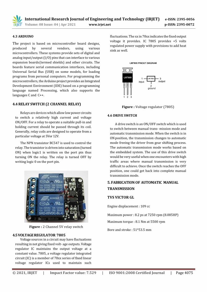
4.5 VOLTAGE REGULATOR 7805 Voltage sources in a circuit may have fluctuations
resulting in not giving fixed volt- age outputs. Voltage
regulator IC maintains the output voltage at a
constant value. 7805, a voltage regulator integrated
circuit (IC) is a member of 78xx series of fixed linear
voltage regulator ICs used to maintain such
fluctuations. The xx in 78xx indicates the fixed output
voltage it provides. IC 7805 provides +5 volts
regulated power supply with provisions to add heat
sink as well.
Figure : Voltage regulator (7805)
4.6 DRIVE SWITCH
A drive switch is an ON/OFF switch which is used
to switch between manual trans- mission mode and
automatic transmission mode. When the switch is in
ON position, the transmission changes to automatic
mode freeing the driver from gear shifting process.
The automatic transmission mode works based on
the embedded system. The use of this drive switch
would be very useful when one encounters with high
traffic areas where manual transmission is very
difficult to achieve. Once the switch reaches the OFF
position, one could get back into complete manual
transmission mode.
5. FABRICATION OF AUTOMATIC MANUAL
TRANSMISSION
TVS VICTOR GL
Engine displacement : 109 cc
Maximum power : 8.2 ps at 7250 rpm (8.085HP)
Maximum torque : 8.1 Nm at 5500 rpm
Bore and stroke : 51*53.5 mm

International Research Journal of Engineering and Technology (IRJET) e-ISSN: 2395-0056
Volume: 08 Issue: 04 | Apr 2021 www.irjet.net p-ISSN: 2395-0072
© 2021, IRJET | Impact Factor value: 7.529 | ISO 9001:2008 Certified Journal | Page 4076
Figure 4.1: TVS Victor GL Engine
Flow chart of the program
LOAD TEST FOR EFFICIENCY COMPARISON
• To develop a test rig for the comparison of the
transmission efficiencies of continuous
variable transmission, manual transmission
and automatic manual transmission.
• To find the most fuel efficient transmission.
• Performance analysis to study the effect of brake power on total fuel consumption, specific fuel consumption, brake thermal efficiency, indicated thermal efficiency and mechanical efficiency.
6. RESULTS AND DISCUSSIONS
6.1 COMPARISON OF TOTAL FUEL CONSUMPTION
The figure compares the total fuel consumption of
CVT, MT and AMT at varying percentage loads. The
TFC curves of three of the transmissions show a non-
uniform trend. In case of CVT, the consumption of fuel
increases with load reaching its maximum at about
80% load. But there is a sudden dip in the curve at
35% load.
It is observed that for both AMT and MT, the
maximum amount of fuel is consumed at the start of
loading followed by a sudden fall in the total fuel
consumption which may be due to the high starting
torque. But on comparison with MT, the fuel
consumption has slightly reduced in AMT
approximately by more than 1%.
Fig Total fuel consumption vs % Load 6.2 COMPARISON OF SPECIFIC FUEL CONSUMPTION
The figure compares the Specific Fuel
Consumption (SFC) of CVT, MT and AMT at varying
percentage loads. The value of specific fuel
consumption obtained for AMT is lesser than that of
MT.

International Research Journal of Engineering and Technology (IRJET) e-ISSN: 2395-0056
Volume: 08 Issue: 04 | Apr 2021 www.irjet.net p-ISSN: 2395-0072
© 2021, IRJET | Impact Factor value: 7.529 | ISO 9001:2008 Certified Journal | Page 4077
Sfc = TFC/pb Kg/hr-Kw
Fig Specific fuel consumption vs % Load
At no load condition, Pb = 0. Hence the SFC curve starts
from infinity. With the increase in load, the SFC value
initially tends to increase up to 15% load (approx.).
With further increase in load, the SFC value tends to
decrease for AMT and MT but this decrease is non-
uniform in case of CVT as the plot indicated above
moves in a zigzag manner. At approximately 80%
load, the SFC value of AMT and MT approaches to that
of the CVT. Thus, it can be concluded that CVT is more
fuel efficient than AMT which follows next and is lesser
for MT. The approximate percentage de- crease in SFC
of AMT compared to MT is 1.02%.Better SFC in CVT
over MT and AMT may be due to difference in their
engine displacement, year of make etc
6.3 COMPARISON OF BRAKE THERMAL EFFICIENCY
Brake thermal efficiency is the ratio of energy in
brake power to the input fuel energy in appropriate
units. The variation of brake thermal efficiencies of the
engines with CVT, AMT and MT are compared in figure .
From the test results it was observed that with the
increase in percentage load the brake thermal
efficiency increases. The brake thermal efficiency
increases gradually with load for both AMT and MT.
While comparing the brake thermal efficiencies of AMT
and MT, it is evident from the graph that AMT is much
more efficient than MT approximately by 1.22%. But in
case of CVT, the increase in efficiency with load is found
to show a non-uniform trend initially increasing and
then decreasing and again goes on increasing.
The maximum brake thermal efficiency is obtained at
about 35% load in CVT but in case of AMT and MT it is
attained at about 80% load. At the same time, it is
observed that the brake thermal efficiency of CVT is
always greater for varying loads followed by AMT and
then MT.
Better thermal efficiency in CVT over MT and AMT may
be due to difference in their engine displacement, year
of make etc
Fig Brake thermal efficiency vs % Load
CONCLUSIONS
AMT is an idea under incubation for the past few
years. It has been used in many four wheelers, but not
in two wheelers due to the bulk size of its
components. If AMT is needed to be brought in two
wheelers it is only possible through a fully electronic
control system consisting of actuators, sensors and
relay circuits. And in our system, we are just proud to
say that we have achieved it to a great extent. We are
successful in controlling the clutch and gear and its
shifting accordingly.
Moreover, using the load test for transmission
efficiency comparison, AMT is found to be much more
efficient than the MT in two wheelers at varying
loads. It has several advantages as it allows infinite
number of gear ratios, better response to changing
conditions and facilitates smoother ride. But AMT is
more costly than MT.
The present technologies are focused in
developing fuel efficient vehicles and this is an
important part of our work. With AMT, we can
achieve fast transmission between gears and speed

International Research Journal of Engineering and Technology (IRJET) e-ISSN: 2395-0056
Volume: 08 Issue: 04 | Apr 2021 www.irjet.net p-ISSN: 2395-0072
© 2021, IRJET | Impact Factor value: 7.529 | ISO 9001:2008 Certified Journal | Page 4078
change. This reduces the wastage of fuel during
slowing down of the vehicle, to change gear. Thus, fast
shifting of gears add on to increasing the mileage of
the vehicle, compared to the others.
REFERENCES [1] M. S. Kumbhar1, D. R Panchagade, A Literature Review
on Automated Manual Transmission (AMT) IJSRD- International Journal for Scientific Research &Development— Vol. 2, Issue 03, 2014, pp. 27-33.
[2] Makarand S Kumbhar, DhananjayPanchagade, Review and Efficiency eval- uation of Automated Manual Transmission (AMT), Proceedings of BLAZE- 2014 International Conference, Buldana, India.ISBN: 978-93-81188-43-9, March 13-14, 2014, pp. 7-12.
[3] D Simmer, The contribution of Transmission to vehicle fuel economy, AU- TOTECH, volume 34, 1995, pp.135-145.
[4] R. P. G. Heath and A. J. Child, Zeroshift Automated Manual Transmission (AMT), SAE Paper No. 2007-26-061, (2007), pp.693-696.
[5] Yoshinori Taguchi, Yoshitaka Soga, Akira Mineno, Development of an Auto- mated manual Transmission system Based on Robust Design, SAE Paper No. 2003-01- 0592, SAE World Congress, Detroit, Michigan, March 3-6, 2003
[6] B Mashadi, A Kazemkhani, R BaghaeiLakeh, An automatic gear-shifting strat- egy for manual transmissions, IMechE, Systems and Control Engineering, vol- ume 221 (2007), pp.757-758
[7] Magnus Pettersson and Lars Nielsen, Gear Shifting by Engine Control, IEEE transactions on control systems technology, volume 8 (2000), pp. 495-507
[8] P. SarathBabu, Analysis of Developing New Smart Systems in Automobile Transmissions The International Journal Of Science & Techno ledge (ISSN 2321 919X)
[9] RomeshMakwana, RajnishKatarne, International Journal Of Engineering Sci- ences & Research Technology, Analysis of Auto-Gear Shifting Mechanism on different Load Conditions ISSN: 2277-9655 Scientific Journal Impact Factor: 3.449ISRA), Impact Factor: 1.852.