f6 series 2-way, ansi class 150 butterfl y valve … · f6350-150shp 14” 6857 90 392 914 1646...
TRANSCRIPT

800-543-9038 USA 866-805-7089 CANADA 203-791-8396 LATIN AMERICA / CARIBBEAN
26
Technical DataService chilled, hot water, 60% glycol,
steam to 50 psiFlow characteristic modifi ed equal percentage, unidirectionalControllable fl ow range 82°Sizes 2” to 24"Type of end fi tting for use with ASME/class 125/150 fl angeMaterials
BodyDiscSeatShaftGland sealBushings
carbon steel full lug316 stainless steelRPTFE17-4 PH stainlessPTFEglass backed PTFE
Media temperature range -20°F to 400°F [-30°C to 204°C]Body pressure rating ANSI Class 150Close-off pressure 285 psiRangeability 100:1 (for 30 deg to 70 deg range)Maximum velocity 32 FPSLeakage bubble tight
• Bubble tight shut-off to ANSI Class 150 Standards• Long stem design allows for 2” insulation minimum• Valve Face-to-face dimensions comply with API 609 & MSS-SP-68• Designed to be installed between ASME/ANSI B16.5 Flanges• Completely assembled and tested, ready for installation
ApplicationThese valves are designed to meet the needs of HVAC and Commercial applications requiring positive shut-off for liquids at higher pressures andtemperatures. Typical applications include chiller isolation, cooling towerisolation, change-over systems, large air handler coil control, bypass andprocess control applications. The large Cv values provide for an economicalcontrol valve solution for larger fl ow applications.
Dead End ServiceUtilizes larger retainer ring set screws to allow the valve to be placed at the end ofthe line without a down stream fl ange in either fl ow direction while still holding full pressure.
MOD ON/OFFValve Size Cv 10° 20° 30° 40° 50° 60° 70° 80° 90°F650-150SHP 2” 102 1.50 6.10 14 26 39 56 77 99 102F665-150SHP 2½” 146 2.20 8.80 20 37 55 80 110 142 146F680-150SHP 3” 228 3.40 14 32 57 87 125 171 221 228F6100-150SHP 4” 451 6.80 27 63 114 171 248 338 437 451F6125-150SHP 5” 714 11 43 100 180 271 393 536 693 714F6150-150SHP 6” 1103 17 66 154 278 419 607 827 1070 1103F6200-150SHP 8” 2064 31 124 289 520 784 1135 1548 2002 2064F6250-150SHP 10” 3517 53 211 492 886 1336 1934 2638 3411 3517F6300-150SHP 12” 4837 73 290 677 1219 1838 2660 3628 4692 4837F6350-150SHP 14” 6857 90 392 914 1646 2481 3592 4898 6530 6857F6400-150SHP 16” 9287 132 531 1230 2229 3361 4865 6634 8845 9287F6450-150SHP 18” 11400 171 684 1596 3873 4332 6270 8550 11270 11400F6500-150SHP 20” 14420 207 828 1932 3478 5244 7590 10350 13800 14420F6600-150SHP 24” 22050 315 1260 2940 5292 7890 11550 15750 21000 22050
F6 Series 2-Way, ANSI Class 150 Butterfl y ValveReinforced Tefl on Seat, 316 Stainless Disc
2-way Valves Suitable Actuators
Valve Nominal
SizeType Non Fail-Safe
Fail-Safe
Spring Return Electronic
Cv 90°
Cv 60° Inches ANSI 150 2-way 150 300 150 300 150 300
102 56 2 F650-150SHP
GM S
erie
s
PR S
erie
s
GM S
erie
s
PR S
erie
s
AF S
erie
s
AF S
erie
s
GK S
erie
s
GK S
erie
s
146 80 2½ F665-150SHP
228 125 3 F680-150SHP
451 248 4 F6100-150SHP
714 392 5 F6125-150SHP
PKR PK
R
1103 607 6 F6150-150SHP
2064 1135 8 F6200-150SHP
SY S
erie
s (2
Yea
r War
rant
y)
SY (2
Yea
r War
rant
y)3517 1934 10 F6250-150SHP
4837 2660 12 F6300-150SHP
6857 3592 14* F6350-150SHP
9287 4865 16* F6400-150SHP
11400 6270 18* F6450-150SHP
14420 7590 20* F6500-150SHP
22050 11550 24* F6600-150SHP
O509
04 -
02/1
2 - S
ubje
ct to
cha
nge.
© B
elim
o Ai
rcon
trols
(USA
), In
c.

800-543-9038 USA 866-805-7089 CANADA 203-791-8396 LATIN AMERICA / CARIBBEAN
27
Maximum Dimensions (Inches)Valve Size Cv 90° A B C D(Max) BHC No. of Holes Lug Bolt Actuator Close-Off (PSI)F650-150SHP 2” 102 1.75 9.00 9.00 19.50 4.75 4 5/8-11 UNC
2*AF
150 Spring Return
F665-150SHP 2½” 146 1.88 9.00 9.00 20.00 5.50 4 5/8-11 UNC 150F680-150SHP 3” 228 1.92 9.00 9.00 20.50 6.00 4 5/8-11 UNC 150F6100-150SHP 4” 451 2.13 9.00 9.00 21.00 7.50 8 5/8-11 UNC 150F650-150SHP 2” 102 1.75 9.00 9.00 19.50 4.75 4 5/8-11 UNC
GK
285 Electronic Fail-Safe
F665-150SHP 2½” 146 1.88 9.00 9.00 20.00 5.50 4 5/8-11 UNC 285F680-150SHP 3” 228 1.92 9.00 9.00 20.50 6.00 4 5/8-11 UNC 285F6100-150SHP 4” 451 2.13 9.00 9.00 21.00 7.50 8 5/8-11 UNC 150F6100-150SHP 4” 451 2.13 9.00 9.00 21.00 7.50 8 5/8-11 UNC 2*GK 285F650-150SHP 2” 102 1.75 9.00 9.00 19.50 4.75 4 5/8-11 UNC
GM
285
Non-Spring ReturnElectronic Fail-Safe (K)
F665-150SHP 2½” 146 1.88 9.00 9.00 20.00 5.50 4 5/8-11 UNC 285F680-150SHP 3” 228 1.92 9.00 9.00 20.50 6.00 4 5/8-11 UNC 285F6100-150SHP 4” 451 2.13 9.00 9.00 21.00 7.50 8 5/8-11 UNC 150F6100-150SHP 4” 451 2.13 9.00 9.00 21.00 7.50 8 5/8-11 UNC 2*GM 285F650-150SHP 2” 102 1.75 10.00 15.00 14.00 4.75 4 5/8-11 UNC
PR/PK
285F665-150SHP 2½” 146 1.88 10.00 16.00 14.00 5.50 4 5/8-11 UNC 285F680-150SHP 3” 228 1.92 10.00 17.00 15.00 6.00 4 5/8-11 UNC 285F6100-150SHP 4” 451 2.13 10.00 18.00 16.00 7.50 8 5/8-11 UNC 285F6125-150SHP 5” 714 2.25 10.00 19.00 16.00 8.50 8 3/4-10 UNC 285F6150-150SHP 6” 1103 2.29 10.00 20.00 17.00 9.50 8 3/4-10 UNC 285F6200-150SHP 8” 2064 2.50 12.00 12.00 32.00 11.75 8 3/4-10 UNC SY4… 285F6250-150SHP 10” 3517 2.81 12.00 12.00 33.00 14.25 12 7/8-9 UNC SY4… 285
F6300-150SHP 12” 4837 3.23 12.00 12.00 35.00 17.00 12 7/8-9 UNCSY4… 150SY5… 285
F6350-150SHP 14” 6857 3.62 14.00 14.00 36.00 18.75 12 1-8 UNCSY5… 150
SY7…285150
F6400-150SHP 16” 9287 4.00 14.00 14.00 37.50 21.25 16 1-8 UNC SY8… 285
F6450-150SHP 18” 11400 4.50 14.00 14.00 42.25 22.75 16 1 1/8-8 UNCSY7… 150SY8… 285
F6500-150SHP 20” 14420 5.00 14.00 14.00 49.50 25.00 20 1 1/8-8 UNCSY8… 150SY10… 285
F6600-150SHP 24” 22050 6.06 14.00 14.00 56.25 29.50 20 1 1/4-8 UNC SY10… 150
F6 Series 2-Way, ANSI Class 150 Butterfl y ValveReinforced Tefl on Seat, 316 Stainless Disc
Dimension “A” does not include flange gaskets. (2 required per valve)
Application Notes1. Valves are rated at 285 psi differential pressure in the closed position
@ 100°F media temperature.2. Valves are furnished with lugs tapped for use between ANSI Class 125/150
fl anges conforming to ANSI B16.5 Standards.3. 2-way assemblies are furnished assembled, calibrated and tested, ready for
installation.4. Dimension “D” allows for actuator(s) removal without the need to remove the
valve from the pipe.5. Weather shields are available, dimensional data furnished upon request.6. Flange gaskets (2 required, not provided with valve) MUST be used between
valve and ANSI fl ange.7. Flange bolts are not included with the valve. These are furnished by others.
Dimensions
D
B C
A
BHCD1
02
SHP series valves have a preferred flow direction.
Pref
erre
dFlo
wra
te
A
C
B
D
O509
04 -
02/1
2 - S
ubje
ct to
cha
nge.
© B
elim
o Ai
rcon
trols
(USA
), In
c.

800-543-9038 USA 866-805-7089 CANADA 203-791-8396 LATIN AMERICA / CARIBBEAN
28
• Bubble tight shut-off to ANSI Class 150 Standards• Long stem design allows for 2” insulation minimum• Valve Face-to-face dimensions comply with API 609 & MSS-SP-68• Designed to be installed between ASME/ANSI B16.5 Flanges• Completely assembled and tested, ready for installation• Tees comply with ASME/ANSI B16.1 Class 125 Flanges
ApplicationThese valves are designed to meet the needs of HVAC and Commercial applications requiring positive shut-off for liquids at higher pressures andtemperatures. Typical applications include chiller isolation, cooling towerisolation, change-over systems, large air handler coil control, bypass andprocess control applications. The large Cv values provide for an economicalcontrol valve solution for larger fl ow applications.
Dead End ServiceUtilizes larger retainer ring set screws to allow the valve to be placed at the end ofthe line without a down stream fl ange in either fl ow direction while still holding full pressure.
MOD ON/OFFValve Size Cv 10° 20° 30° 40° 50° 60° 70° 80° 90°F750-150SHP 2” 102 1.50 6.10 14 26 39 56 77 99 102F765-150SHP 2½” 146 2.20 8.80 20 37 55 80 110 142 146F780-150SHP 3” 228 3.40 14 32 57 87 125 171 221 228
F7100-150SHP 4” 451 6.80 27 63 114 171 248 338 437 451F7125-150SHP 5” 714 11 43 100 180 271 393 536 693 714F7150-150SHP 6” 1103 17 66 154 278 419 607 827 1070 1103F7200-150SHP 8” 2064 31 124 289 520 784 1135 1548 2002 2064F7250-150SHP 10” 3517 53 211 492 886 1336 1934 2638 3411 3517F7300-150SHP 12” 4837 73 290 677 1219 1838 2660 3628 4692 4837F7350-150SHP 14” 6857 103 411 960 1728 2606 3592 5143 6651 6857F7400-150SHP 16” 9287 139 557 1300 2340 3529 4865 6965 9008 9287F7450-150SHP 18” 11400 171 684 1596 2873 4332 6270 8550 11058 11400
F7 Series 3-Way, ANSI Class 150 Butterfl y ValveReinforced Tefl on Seat, 316 Stainless Disc
Technical DataService chilled, hot water, 60% glycol,
steam to 50 psiFlow characteristic modifi ed equal percentage, unidirectionalControllable fl ow range 82°Sizes 2" to 18"Type of end fi tting for use with ASME/class 125/150 fl angesMaterials
BodyDiscSeatShaftGland sealBushings
carbon steel full lug316 stainless steelRPTFE17-4 PH stainlessPTFEglass backed PTFE
Media temperature range -20°F to 400°F [-30°C to 204°C]Body pressure rating ANSI Class 150 Close-off pressure 285 psiRangeability 100:1 (for 30 deg to 70 deg range)Maximum velocity 32 FPSLeakage bubble tight
3-way Valves Suitable Actuators
Valve Nominal
SizeType Non Fail-Safe Electronic
Fail-Safe
Cv 90°
Cv 60° Inches ANSI 150 3-way 150 300 150 300
2 F750-150SHP
GM S
erie
s
PR S
erie
s
GM
Serie
s
PR S
erie
s
GK S
erie
s
GK S
erie
s
2½ F765-150SHP 3 F780-150SHP
4 F7100-150SHP PKR
5 F7125-150SHP
SY S
erie
s (2
Yea
r War
rant
y)
SY S
erie
s (2
Yea
r War
rant
y)6 F7150-150SHP
8 F7200-150SHP
10 F7250-150SHP
12 F7300-150SHP
14* F7350-150SHP
16* F7400-150SHP
18* F7450-150SHP
O509
04 -
02/1
2 - S
ubje
ct to
cha
nge.
© B
elim
o Ai
rcon
trols
(USA
), In
c.
102146
228
451
714
1103
2064
3517
4837
6857
9287
11400
80
125
248
393
607
1135
1934
2660
3592
4865
6270
56

800-543-9038 USA 866-805-7089 CANADA 203-791-8396 LATIN AMERICA / CARIBBEAN
29
Maximum Dimensions (Inches)Valve Size Cv 90° A B C D(Max) BHC No. of Holes Lug Bolt Actuator Close-Off (PSI)F750-150SHP 2” 102 4.50 6.38 6.38 16.50 4.75 4 5/8-11 UNC
GK
150 Electronic Fail-Safe
F765-150SHP 2½” 146 5.00 6.88 6.88 17.00 5.50 4 5/8-11 UNC 150
F780-150SHP 3” 228 5.50 7.56 7.56 17.50 6.00 4 5/8-11 UNC 150
F750-150SHP 2” 102 4.50 6.38 6.38 16.50 4.75 4 5/8-11 UNC
2*GK
285
F765-150SHP 2½” 146 5.00 6.88 6.88 17.00 5.50 4 5/8-11 UNC 285
F780-150SHP 3” 228 5.50 7.56 7.56 17.50 6.00 4 5/8-11 UNC 285
F750-150SHP 2” 102 4.50 6.38 6.38 16.50 4.75 4 5/8-11 UNC
GM
150
Non-Spring ReturnElectronic Fail-Safe (K)
F765-150SHP 2½” 146 5.00 6.88 6.88 17.00 5.50 4 5/8-11 UNC 150F780-150SHP 3” 228 5.50 7.56 7.56 17.50 6.00 4 5/8-11 UNC 150F7100-150SHP 4” 451 6.50 8.63 8.63 18.00 7.50 8 5/8-11 UNC 150F750-150SHP 2” 102 4.50 6.38 6.38 16.50 4.75 4 5/8-11 UNC
2*GM285
F765-150SHP 2½” 146 5.00 6.88 6.88 17.00 5.50 4 5/8-11 UNC 285F780-150SHP 3” 228 5.50 7.56 7.56 17.50 6.00 4 5/8-11 UNC 285F750-150SHP 2” 102 4.50 6.38 6.38 14.00 4.75 4 5/8-11 UNC
PR/PK
285F765-150SHP 2½” 146 5.00 6.88 6.88 14.50 5.50 4 5/8-11 UNC 285F780-150SHP 3” 228 5.50 7.56 7.56 15.00 6.00 4 5/8-11 UNC 285F7100-150SHP 4” 451 6.50 8.63 8.63 16.00 7.50 8 5/8-11 UNC 285F7125-150SHP 5” 714 7.50 9.75 9.75 24.25 8.50 8 3/4-10 UNC
SY4…285
F7150-150SHP 6” 1103 8.00 10.25 10.25 24.75 9.50 8 3/4-10 UNC 285F7200-150SHP 8” 2064 9.00 11.50 11.50 32.00 11.75 8 3/4-10 UNC SY4… 150
F7250-150SHP 10” 3517 11.00 13.81 13.81 33.00 14.25 12 7/8-9 UNCSY4… 150SY5… 285
F7300-150SHP 12” 4837 12.00 15.81 15.81 35.00 17.00 12 7/8-9 UNCSY5… 150SY7… 285
F7350-150SHP 14” 6857 14.00 17.62 17.62 36.00 18.75 12 1-8 UNC SY7… 285
F7400-150SHP 16” 9287 15.00 19.00 19.00 37.50 21.25 16 1-8 UNCSY7… 150SY9… 285
F7450-150SHP 18” 11400 16.50 21.00 21.00 42.25 22.75 16 1 1/8-8 UNCSY8… 150SY10… 285
F7 Series 3-Way, ANSI Class 150 Butterfl y ValveReinforced Tefl on Seat, 316 Stainless Disc
Note: For tee confi guration, please refer to page 5.
Dimensions “A, B and C” do not include fl ange gaskets. (3 required per valve)
Application Notes1. Valves are rated at 285 psi differential pressure in the closed position
@ 100°F media temperature.2. Valves are furnished with lugs tapped for use between
ANSI Class 125/150 fl anges conforming to ANSI B16.5 Standards.3. 3-way assemblies are furnished assembled with Tee, calibrated and tested,
ready for installation. All 3-way assemblies require the customer to specifythe 3-way confi guration code prior to order entry to guarantee correct place-ment of valves and actuator(s) on the assembly.
4. Dimension “D” allows for actuator(s) removal without the need to removethe valve from the pipe.
5. Weather shields are available, dimensional data furnished upon request.6. Dual actuated valves have single actuators mounted on each valve shaft.7. Flange gaskets (3 required, not provided with valve) MUST be used between
valve and ANSI fl ange.8. Flange bolts are not included with the valve. These are furnished by others.
SHP series valves have a preferred flow direction.
Pref
erre
dFlo
wra
te
Dimensions
0
S
D
C
A B
D104
B,C
D
A
O509
04 -
02/1
2 - S
ubje
ct to
cha
nge.
© B
elim
o Ai
rcon
trols
(USA
), In
c.

800-543-9038 USA 866-805-7089 CANADA 203-791-8396 LATIN AMERICA / CARIBBEAN
43
Application:The SY actuators are NEMA 4X rated and designed to meetthe needs of HVAC and Commercial applications. Offered on Belimo standard and high performance valve series, theseactuators are available for on/off and modulating applications.Depending on the application, they are available in 24 VAC/VDC, 120 VAC and 230 VAC.
Technical Data
Electrical connection ½” conduit connector,screw terminals
Motor protection H Class insulation (SY-1), F Class (SY-2…5)
Gear train high alloy steel gear sets, self locking
Operating range (SY…-24) on/off, floating point(SY...24MFT) 2-10 VDC, 4-20 mA, 0-10 VDC
Sensitivity (SY…24MFT) 0.4 mA/200mV
Reversal hysteresis (SY…24MFT)1.0 mA/500mV
Feedback (SY…24MFT) 2-10 VDC
Angle of rotation 90°
Direction of rotation reversible
Position indication top mounted domed indicator
Internal humidity control resistive heating element
Auxiliary switches factory set for 5° and 85° change of stateSY1: (2) SPDT, min 1 mA, 24 VAC; max 3A, 250 VAC.SY4-12: (2) SPDT, min 1 mA, 24 VAC; max 5A, 250 VAC.
Ambient temperature -22°F to +150°F [-30°C to +65°C]
Humidity range up to 95%
Housing type IP67, NEMA 4X
Housing material die cast aluminum alloy
Agency listings ISO, CE, cCSAus
Power Supply 24 VAC/VDC 50/60Hz, single phase
Model Torque SpeedPower
Consumption
Duty Cycle
Override WeightOn/Off MFT
SY4-24(MFT) 400Nm/3560 in-lbs 16s 6.0A 30% 75% Hand Wheel 22kg/48.5 lb.
SY5-24(MFT) 500Nm/4450 in-lbs 22s 6.5A 30% 75% Hand Wheel 22kg/48.5 lb.
SY...24V Series Non-Spring Return ActuatorTechnical Data - 24 VAC
O509
04 -
02/1
2 - S
ubje
ct to
cha
nge.
© B
elim
o Ai
rcon
trols
(USA
), In
c.

800-543-9038 USA 866-805-7089 CANADA 203-791-8396 LATIN AMERICA / CARIBBEAN
44
Application:The SY actuators are NEMA 4X rated and designed to meetthe needs of HVAC and Commercial applications. Offered on Belimo standard and high performance valve series, theseactuators are available for on/off and modulating applications.Depending on the application, they are available in 24 VAC/VDC, 120 VAC and 230 VAC.
Technical Data
Electrical connection ½” conduit connector, screw terminals
Motor protection H Class insulation (SY-1), F Class (SY-2…12)
Gear train high alloy steel gear sets,self locking
Operating range (SY…-110) on/off, floating point(SY...120MFT) 2-10 VDC, 4-20 mA, 0-10 VDC
Sensitivity (SY…120MFT) 0.4 mA/200mV
Reversal hysteresis (SY…120MFT) 1.0 mA/500mV
Feedback (SY…120MFT) 2-10 VDC
Angle of rotation 90°
Direction of rotation reversible
Position indication top mounted domed indicator
Internal humidity control resistive heating element
Auxiliary switches factory set for 5° and 85° change of stateSY1: (2) SPDT, min 1 mA, 24 VAC; max 3A, 250 VAC.SY4-12: (2) SPDT, min 1 mA, 24 VAC; max 5A, 250 VAC.
Ambient temperature -22°F to +150°F [-30°C to +65°C]
Humidity range up to 95%
Housing type IP67, NEMA 4X
Housing material die cast aluminum alloy
Agency listings ISO, CE, cCSAus
Note: Leakage current is possible (<3.5 mA).Connect ground before applying voltage.
Power Supply 120 VAC 50/60Hz, single phase
Model TorqueSpeed 60Hz
Speed 50Hz
Power Consumption
Duty Cycle
Override WeightOn/Off Proportional
SY4-120(MFT) 400Nm/3560 in-lbs 16s 18s 1.3A 30% 75% Hand Wheel 22kg/48.5 lb.
SY5-120(MFT) 500Nm/4450 in-lbs 22s 25s 1.5A 30% 75% Hand Wheel 22kg/48.5 lb.
SY6-120(MFT) 650Nm/5785 in-lbs 28s 31s 1.8A 30% 75% Hand Wheel 22kg/48.5 lb.
SY7-120(MFT) 1000Nm/8900 in-lbs 46s 55s 3.2A 30% 75% Hand Wheel 36kg/79.5 lb.
SY8-120(MFT) 1500Nm/13350 in-lbs 46s 55s 4.0A 30% 75% Hand Wheel 36kg/79.5 lb.
SY9-120(MFT) 2000Nm/17800 in-lbs 58s 70s 3.2A 30% 50% Hand Wheel 56kg/123.5 lb.
SY10-120(MFT) 2500Nm/22250 in-lbs 58s 70s 4.0A 30% 50% Hand Wheel 56kg/123.5 lb.
SY11-120(MFT) 3000Nm/26700 in-lbs 58s 70s 3.0A 30% 50% Hand Wheel 56kg/123.5 lb.
SY12-120(MFT) 3500Nm/31150 in-lbs 58s 70s 4.0A 30% 50% Hand Wheel 56kg/123.5 lb.
SY...120V Series Non-Spring Return ActuatorTechnical Data - 120 VAC
O509
04 -
02/1
2 - S
ubje
ct to
cha
nge.
© B
elim
o Ai
rcon
trols
(USA
), In
c.

800-543-9038 USA 866-805-7089 CANADA 203-791-8396 LATIN AMERICA / CARIBBEAN
45
Application:The SY actuators are NEMA 4X rated and designed to meet the needs of HVAC and Commercial applications. Offered on Belimo standard and high performance valve series, theseactuators are available for on/off and modulating applications.Depending on the application, they are available in 24 VAC/VDC, 120 VAC and 230 VAC.
Power Supply 230 VAC 50/60Hz, single phase
Model Torque Speed 60Hz
Speed 50Hz
Power Consumption
Duty Cycle
Override WeightOn/Off MFT
SY4-230(MFT) 400Nm/3560 in-lbs 16s 18s 0.6A 30% 75% Hand Wheel 22kg/48.5 lb.
SY5-230(MFT) 500Nm/4450 in-lbs 22s 25s 0.7A 30% 75% Hand Wheel 22kg/48.5 lb.
SY6-230(MFT) 650Nm/5785 in-lbs 28s 31s 0.8A 30% 75% Hand Wheel 22kg/48.5 lb.
SY7-230(MFT) 1000Nm/8900 in-lbs 46s 55s 1.6A 30% 75% Hand Wheel 36kg/79.5 lb.
SY8-230(MFT) 1500Nm/13350 in-lbs 46s 55s 2.0A 30% 75% Hand Wheel 36kg/79.5 lb.
SY9-230(MFT) 2000Nm/17800 in-lbs 58s 70s 1.6A 30% 50% Hand Wheel 56kg/123.5 lb.
SY10-230(MFT) 2500Nm/22250 in-lbs 58s 70s 2.0A 30% 50% Hand Wheel 56kg/123.5 lb.
SY11-230(MFT) 3000Nm/26700 in-lbs 58s 70s 1.6A 30% 50% Hand Wheel 56kg/123.5 lb.
SY12-230(MFT) 3500Nm/31150 in-lbs 58s 70s 2.2A 30% 50% Hand Wheel 56kg/123.5 lb.
Technical Data
Electrical connection ½” conduit connector, screw terminals
Overload protection thermally protected 135°C cut-out
Motor protection H Class insulation (SY-1), F Class (SY-2…12)
Gear train high alloy steel gear sets,self locking
Operating range (SY…-220) on/off, floating point(SY...230MFT) 2-10 VDC, 4-20 mA, 0-10 VDC
Sensitivity (SY…230MFT) 0.4 mA/200mV
Reversal hysteresis (SY…230MFT) 1.0 mA/500mV
Feedback (SY…230MFT) 2-10 VDC
Angle of rotation 90°
Direction of rotation reversible
Position indication top mounted domed indicator
Internal humidity control resistive heating element
Auxiliary switches factory set for 5° and 85° change of stateSY1: (2) SPDT, min 1 mA, 24 VAC; max 3A, 250 VAC.SY4-12: (2) SPDT, min 1 mA, 24 VAC; max 5A, 250 VAC.
Ambient temperature -22°F to +150°F [-30°C to +65°C]
Humidity range up to 95%
Housing type IP67, NEMA 4X
Housing material die cast aluminum a lloy
Agency listings ISO, CE, cCSAus
SY...230V Series Non-Spring Return ActuatorTechnical Data - 230 VAC
O509
04 -
02/1
2 - S
ubje
ct to
cha
nge.
© B
elim
o Ai
rcon
trols
(USA
), In
c.

800-543-9038 USA 866-805-7089 CANADA 203-791-8396 LATIN AMERICA / CARIBBEAN
46
D
A
BC
A
A
B
BC
C
D
D
SY-9~12...
SY-7~8...
SY-2~6...
MODEL DIM A (MAX)Add to Dim A for
cover removal DIM B DIM C (MAX) DIM D
Inches [mm] Inches [mm] Inches [mm] Inches [mm] Inches [mm]
SY4~6 12.40 [315] 8.86 [225] 9.21 [234] 14.96 [380] 11.81 [300]
SY7~8 16.54 [420] 8.86 [225] 9.21 [234] 17.72 [450] 13.39 [340]
SY9~12 23.23 [590] 8.86 [225] 10.24 [260] 18.50 [470] 13.78 [350]
SY... Series Non-Spring Return ActuatorDimensions
O509
04 -
02/1
2 - S
ubje
ct to
cha
nge.
© B
elim
o Ai
rcon
trols
(USA
), In
c.

800-543-9038 USA 866-805-7089 CANADA 203-791-8396 LATIN AMERICA / CARIBBEAN
47
Butterfly Valve Actuators
Power Supply 24 VAC/VDC Single Phase
Model # Torque Speed50 Hz/60 Hz
Current Draw(50 Hz)
Current Draw(60 Hz)
W (50 Hz)
W (60 Hz)
VA(50 Hz)
VA(60 Hz) Override Weight
PRBUP-3-T* 1400 in-lbs/ 160 Nm 35 seconds 0.8 A 0.8 A 20 20 20 20 Manual override crank 5.8 kg/12.8 lbs.
PRXUP-3-T* 1400 in-lbs/ 160 Nm 35, 30-120 seconds 0.8 A 0.8 A 20 20 20 20 Manual override crank 5.8 kg/12.8 lbs.
SY4-24 3540 in-lbs/ 400 Nm 30 seconds 9.5 A 9.5 A 208 212 228 228 Hand wheel 22 kg/48.5 lbs.
SY5-24 4430 in-lbs/ 500 Nm 35 seconds 9.3 A 9.4 A 178 168 223 227 Hand wheel 22 kg/48.5 lbs.
Power Supply 120 VAC Single Phase
Model # Torque Speed 50 Hz Speed 60 Hz Current Draw(50 Hz)
Current Draw(60 Hz)
W (50 Hz)
W(60 Hz)
VA(50 Hz)
VA(60 Hz) Override Weight
PRBUP-3-T* 1400 in-lbs/ 160 Nm 35 seconds 35 seconds 0.2 A 0.2 A 18 18 23 23 Manual override crank 5.8 kg/12.8 lbs.
PRXUP-3-T* 1400 in-lbs/ 160 Nm 35, 30-120 seconds
35, 30-120 seconds 0.2 A 0.2 A 18 18 23 23 Manual override crank 5.8 kg/12.8 lbs.
SY4-110 3540 in-lbs/ 400 Nm 21 seconds 18 seconds 2.2 A 1.8 A 240 196 264 216 Hand wheel 22 kg/48.5 lbs.
SY5-110 4430 in-lbs/ 500 Nm 29 seconds 25 seconds 2.2 A 1.8 A 242 193 264 216 Hand wheel 22 kg/48.5 lbs.
SY6-110 5750 in-lbs/ 650 Nm 37 seconds 32 seconds 2.2 A 1.8 A 247 198 264 216 Hand wheel 22 kg/48.5 lbs.
SY7-110 8850 in-lbs/ 1000 Nm 59 seconds 49 seconds 6.4 A 3.5 A 670 385 768 420 Hand wheel 36 kg/79.5 lbs.
SY8-110 13280 in-lbs/ 1500 Nm 60 seconds 50 seconds 8.2 A 4.8 A 847 514 984 576 Hand wheel 36 kg/79.5 lbs.
SY9-110 17700 in-lbs/ 2000 Nm 68 seconds 57 seconds 2.7 A 2.8 A 304 311 324 336 Hand wheel 72 kg/176.4 lbs.
SY10-110 22130 in-lbs/ 2500 Nm 75 seconds 62 seconds 2.8 A 2.9 A 318 335 336 348 Hand wheel 72 kg/176.4 lbs.
SY11-110 26550 in-lbs/ 3000 Nm 78 seconds 69 seconds 3.3 A 3.6 A 365 387 396 432 Hand wheel 72 kg/176.4 lbs.
SY12-110 30980 in-lbs/ 3500 Nm 72 seconds 60 seconds 3.7 A 3.8 A 415 422 444 456 Hand wheel 72 kg/176.4 lbs.
Power Supply 230 VAC Single Phase
Model # Torque Speed 50 Hz Speed 60 Hz Current Draw(50 Hz)
Current Draw(60 Hz)
W (50 Hz)
W(60 Hz)
VA(50 Hz)
VA(60 Hz) Override Weight
PRBUP-3-T* 1400 in-lbs/ 160 Nm 35 sec. 35 sec. 0.2 A 0.2 A 20 20 52 52 Manual override crank 5.8 kg/12.8 lbs.
PRXUP-3-T* 1400 in-lbs/ 160 Nm 35, 30-120 sec. 35, 30-120 sec. 0.2 A 0.2 A 20 20 52 52 Manual override crank 5.8 kg/12.8 lbs.
SY4-220 3540 in-lbs/ 400 Nm 21 seconds 18 seconds 1.1 A 0.9 A 221 180 253 207 Hand wheel 22 kg/48.5 lbs.
SY5-220 4430 in-lbs/ 500 Nm 29 seconds 25 seconds 1.1 A 0.9 A 216 179 253 207 Hand wheel 22 kg/48.5 lbs.
SY6-220 5750 in-lbs/ 650 Nm 38 seconds 31 seconds 1.0 A 0.9 A 193 177 230 207 Hand wheel 22 kg/48.5 lbs.
SY7-220 8850 in-lbs/ 1000 Nm 58 seconds 48 seconds 1.8 A 1.4 A 381 290 414 322 Hand wheel 36 kg/79.5 lbs.
SY8-220 13280 in-lbs/ 1500 Nm 59 seconds 49 seconds 1.9 A 1.4 A 428 294 437 322 Hand wheel 36 kg/79.5 lbs.
SY9-220 17700 in-lbs/ 2000 Nm 68 seconds 57 seconds 1.6 A 2.4 A 356 509 368 552 Hand wheel 72 kg/176.4 lbs.
SY10-220 22130 in-lbs/ 2500 Nm 73 seconds 62 seconds 1.7 A 2.5 A 377 531 391 579 Hand wheel 72 kg/176.4 lbs.
SY11-220 26550 in-lbs/ 3000 Nm 46 seconds 64 seconds 1.8 A 2.5 A 397 547 414 579 Hand wheel 72 kg/176.4 lbs.
SY12-220 30980 in-lbs/ 3500 Nm 74 seconds 61 seconds 1.8 A 2.4 A 409 505 414 552 Hand wheel 72 kg/176.4 lbs.
*-200 and -250 versions have the same ratings.
O509
04 -
02/1
2 - S
ubje
ct to
cha
nge.
© B
elim
o Ai
rcon
trols
(USA
), In
c.

800-543-9038 USA 866-805-7089 CANADA 203-791-8396 LATIN AMERICA / CARIBBEAN
48
Butterfly Valve Actuators
Power Supply 24 VAC/VDC Single Phase
Model # Torque Speed50 Hz/60 Hz
Current Draw(50 Hz)
Current Draw(60 Hz)
W(50 Hz)
W (60 Hz)
VA(50 Hz)
VA(60 Hz) Override Weight
PRXUP-MFT-T* 1400 in-lbs/160 Nm 30-120 sec. 0.9 A 0.9 A 20 20 20 20 Manual override crank 5.8 kg/12.8 lbs.
PKRXUP-MFT-T* 1400 in-lbs/160 Nm 30-120 sec. 2.2 A 2.2 A 52 52 55 55 Manual override crank 6.4 kg/14.1 lbs.
SY4-24MFT 3540 in-lbs/ 400 Nm 23 seconds 11.0 A 11.0 A 254 251 264 264 Hand wheel 22 kg/48.5 lbs.
SY5-24MFT 4430 in-lbs/ 500 Nm 30 seconds 10.2 A 10.2 A 232 230 245 245 Hand wheel 22 kg/48.5 lbs.
Power Supply 120 VAC Single Phase
Model # Torque Speed 50 Hz
Speed 60 Hz
Current Draw(50 Hz)
Current Draw(60 Hz)
W (50 Hz)
W(60 Hz)
VA(50 Hz)
VA (60 Hz) Override Weight
PRXUP-MFT-T* 1400 in-lbs/160 Nm 30-120 sec. 30-120 sec. 0.2 A 0.2 A 18 18 23 23 Manual override crank 5.8 kg/12.8 lbs.
PKRXUP-MFT-T* 1400 in-lbs/160 Nm 30-120 sec. 30-120 sec. 0.3 A 0.3 A 40 40 43 43 Manual override crank 6.4 kg/14.1 lbs.
SY4-120MFT 3540 in-lbs/ 400 Nm 16 seconds 17 seconds 2.3 A 2.4 A 258 256 276 288 Hand wheel 22 kg/48.5 lbs.
SY5-120MFT 4430 in-lbs/ 500 Nm 21 seconds 21 seconds 2.3 A 2.3 A 216 208 276 276 Hand wheel 22 kg/48.5 lbs.
SY6-120MFT 5750 in-lbs/ 650 Nm 28 seconds 29 seconds 2.2 A 2.2 A 240 236 264 264 Hand wheel 22 kg/48.5 lbs.
SY7-120MFT 8850 in-lbs/ 1000 Nm 41 seconds 44 seconds 1.8 A 1.7 A 198 192 216 204 Hand wheel 36 kg/79.5 lbs.
SY8-120MFT 13280 in-lbs/ 1500 Nm 48 seconds 48 seconds 2.6 A 2.6 A 275 266 312 312 Hand wheel 36 kg/79.5 lbs.
SY9-120MFT 17700 in-lbs/ 2000 Nm 47 seconds 47 seconds 3.6 A 3.4 A 397 382 432 408 Hand wheel 72 kg/176.4 lbs.
SY10-120MFT 22130 in-lbs/ 2500 Nm 52 seconds 51 seconds 4.0 A 4.0 A 450 445 480 480 Hand wheel 72 kg/176.4 lbs.
SY11-120MFT 26550 in-lbs/ 3000 Nm 55 seconds 56 seconds 3.1 A 3.0 A 332 318 372 360 Hand wheel 72 kg/176.4 lbs.
SY12-120MFT 30980 in-lbs/ 3500 Nm 61 seconds 62 seconds 3.6 A 3.4 A 386 368 432 408 Hand wheel 72 kg/176.4 lbs.
Power Supply 230 VAC Single Phase
Model # Torque Speed 50 Hz
Speed60 Hz
Current Draw(50 Hz)
Current Draw(60 Hz)
W (50 Hz)
W (60 Hz)
VA(50 Hz)
VA(60 Hz) Override Weight
PRXUP-MFT-T* 1400 in-lbs/160 Nm 30-120 sec. 30-120 sec. 0.1 A 0.1 A 20 20 52 52 Manual override crank 5.8 kg/12.8 lbs.
PKRXUP-MFT-T* 1400 in-lbs/160 Nm 30-120 sec. 30-120 sec. 0.2 A 0.2 A 40 40 68 68 Manual override crank 6.4 kg/14.1 lbs.
SY4-230MFT 3540 in-lbs/ 400 Nm 16 seconds 17 seconds 1.1 A 1.1 A 222 217 253 253 Hand wheel 22 kg/48.5 lbs.
SY5-230MFT 4430 in-lbs/ 500 Nm 22 seconds 22 seconds 1.1 A 1.0 A 211 200 253 230 Hand wheel 22 kg/48.5 lbs.
SY6-230MFT 5750 in-lbs/ 650 Nm 32 seconds 32 seconds 1.1 A 1.1 A 236 232 253 253 Hand wheel 22 kg/48.5 lbs.
SY7-230MFT 8850 in-lbs/ 1000 Nm 44 seconds 44 seconds 0.9 A 0.8 A 167 157 207 184 Hand wheel 36 kg/79.5 lbs.
SY8-230MFT 13280 in-lbs/ 1500 Nm 55 seconds 57 seconds 1.3 A 1.4 A 288 286 299 322 Hand wheel 36 kg/79.5 lbs.
SY9-230MFT 17700 in-lbs/ 2000 Nm 61 seconds 61 seconds 1.1 A 1.1 A 240 233 253 253 Hand wheel 72 kg/176.4 lbs.
SY10-230MFT 22130 in-lbs/ 2500 Nm 72 seconds 70 seconds 1.4 A 1.4 A 277 284 322 322 Hand wheel 72 kg/176.4 lbs.
SY11-230MFT 26550 in-lbs/ 3000 Nm 44 seconds 48 seconds 2.0 A 1.9 A 376 363 460 437 Hand wheel 72 kg/176.4 lbs.
SY12-230MFT 30980 in-lbs/ 3500 Nm 47 seconds 51 seconds 2.2 A 2.0 A 490 456 506 460 Hand wheel 72 kg/176.4 lbs.
*-200 and -250 versions have the same ratings.
O509
04 -
02/1
2 - S
ubje
ct to
cha
nge.
© B
elim
o Ai
rcon
trols
(USA
), In
c.

800-543-9038 USA 866-805-7089 CANADA 203-791-8396 LATIN AMERICA / CARIBBEAN
52
SY Actuator Wiring Diagram, SY1…5-24V – On/Off SY1…12-120V or 230V On/Off
Observe class 1 and class 2 wiring restrictions.
Transformer sizing = SY actuator draw X 1.25 (safety margin)(Ex. SY2-24 requires 3.0A x 1.25 = 3.75A, 3.75A X 24 VAC = 90VA Transformer).
Indicates an action or condition that may cause irreversible damage to the actuator(s) or associated equipment.
Equipment damage!Power consumption and input impedance must be observed.
CAUTIONIndicates a potentially hazardous situation which, if not avoided, may result in minor or moderate injury. It may also be used to alert against unsafe practices.
Warnings and Cautions appear at appropriate sections throughout this manual. Read these carefully.
Hazard Identification INSTALLATION NOTES
NOTES SY1…5-24
Each actuator should be powered by a single, isolated control transformer.
• Isolation relays must be used in parallel connection of multiple actuators using a common control signal input.• "H" cannot be connected to terminal #3 and #4 simultaneously.
24V AC/DC Transformer
Line Volts
Open
Close
G Ground
1 Common
3 Open
4 Closed
5
6
7
G Ground
1 Common
3 Open
4 Closed
5
6
7 HTR
A
B
C
D
E
F
LS3
A-C (Open Indication)
LS4
D-F (Closed Indication)
Contact Rating: 5A 250 VAC Max.
SY2…5-24
120V or 230V AC/DCG
Open
Close
G
N L1
H L2
HTR
A
B
C
D
E
F
LS3
A-C (Open Indication)
LS4
D-F (Closed Indication)
Contact Rating: 5A 250 VAC Max.
SY2…12-120V or 230V
NOTES SY1…12-120V or 230V
• Caution: Power Supply Voltage• Isolation relays must be used in parallel connection of multiple actuators using a common control signal input.• "H" (L2) cannot be connected to terminal #3 and #4 simultaneously.
SY1-24
A
B
C
E
F
Contact Rating: 5A 125 VAC Max. 3A 250 VAC Max.
A-B (Open Indication)
LS4
LS3
A-E (Closed Indication)
SY1-110 (220)
A
B
C
E
F
Contact Rating: 5A 125 VAC Max. 3A 250 VAC Max.
A-B (Open Indication)
LS4
LS3
A-E (Closed Indication)
SY1 Contact Arrangements
33
33
W54
6_12
Wiring for Control Valves On/Off, 24V, 120/230V
O509
04 -
02/1
2 - S
ubje
ct to
cha
nge.
© B
elim
o Ai
rcon
trols
(USA
), In
c.

800-543-9038 USA 866-805-7089 CANADA 203-791-8396 LATIN AMERICA / CARIBBEAN
54
Each actuator should be powered by a single, isolated control transformer.
"–" wiring to a common is prohibited.
Actuator: SY2…5-24MFT SY2...12-120MFT SY2...12-230MFT
Indicates an action or condition that may cause irreversible damage to the actuator(s) or associated equipment.
CAUTIONIndicates a potentially hazardous situation which, if not avoided, may result in minor or moderate injury. It may also be used to alert against unsafe practices.
this manual. Read these carefully.
Hazard Identification
33
INSTALLATION NOTES
Use of feedback is optional.
APPLICATION NOTES
34
36
Ground shielded wire at control panel chassis. Tape back ground at actuator.
NOTES SY2...5-24MFT NOTES SY2...12-120MFT (230MFT)
Caution:
SY2...5-24MFT
SY2...12-120MFT(230MFT)
A
B
C
E
F
LS4
LS3
1
Y
U5
C1
2
C2
B
A
1
9
8
10
3
2
/-
~/+
Internal Use Only
Internal Use Only
Internal Use Only
Not Used -
Control Signal
Not Used -
Internal Use Only
Internal Use Only
Internal Use Only
Internal Use Only
Power Supply Com
Power Supply Hot 24V AC/DC
Internal Use Only
Feedback
Control Signal (-)
Feedback Signal (+)
Feedback Signal (-)
33
Control Signal (+)
SYx-24MFT
Address
Adaption
PC ToolService Jack
G PE
Y1Y2
3436
Power Supply Com – 120v (N) / 230v (L1)
Power Supply Hot – 120v (H) / 230v (L2)
1
Y
U5
C1
2
C2
B
A
1
9
8
10
3
2
Internal Use Only
Internal Use Only
Internal Use Only
Not Used -
Control Signal
Not Used -
Internal Use Only
Internal Use Only
Internal Use Only
Internal Use Only
Internal Use Only
Feedback
Control Signal (-)
Feedback Signal (+)
Feedback Signal (-)
Control Signal (+)
SYx-230MFT
Address Adaption
PC ToolService Jack
SYx-120MFT
LN
G PE
Y1
Y2
3436
W54
7_2_
11Wiring for Control ValvesProportional, 24V, 120/230V
O509
04 -
02/1
2 - S
ubje
ct to
cha
nge.
© B
elim
o Ai
rcon
trols
(USA
), In
c.

800-543-9038 USA 866-805-7089 CANADA 203-791-8396 LATIN AMERICA / CARIBBEAN
55
SY Actuator Wiring Diagram, SY1…5-24 – Multiple Wiring SY1…12-110 (220) – Multiple Wiring
Observe class 1 and class 2 wiring restrictions.
Transformer sizing = SY actuator draw X 1.25 (safety margin)(Ex. SY2-24 requires 3.0A x 1.25 = 3.75A, 3.75A X 24 VAC = 90VA Transformer).
Indicates an action or condition that may cause irreversible damage to the actuator(s) or associated equipment.
Equipment damage!Power consumption and input impedance must be observed.
Isolation relays are required in parallel applications.The reason parallel applications need isolation relays is that the motor uses two sets of windings, one for each direction. When one is energized to turn the actuator in a specific direction a voltage is generated in the other due to the magnetic field created from the first. It’s called back EMF.This is OK with one actuator because the voltage generated in the second winding isn’t connected to anything so there is no flow; it has no magnetic effect on the motor.On parallel applications without isolation, this EMF voltage energizes the winding it is connected to on the other actuators in the system, the actuators are then trying to turn in both directions at once. The EMF voltage is always less than the supply voltage due to the resistance of the windings, so while the actuator still turns in the commanded direction, the drag from the otherreduces the torque output and causes overheating.
CAUTIONIndicates a potentially hazardous situation which, if not avoided, may result in minor or moderate injury. It may also be used to alert against unsafe practices.
Warnings and Cautions appear at appropriate sections throughout this manual. Read these carefully.
Hazard Identification INSTALLATION NOTES
G Ground
1 Common
3 Open
4 Closed
5 6 7 HTR
A
B
C
D
E
F
LS3
A-C (Open Indication)
LS4
D-F (Closed Indication)
Contact Rating: 5A 250 VAC Max.
G Ground
1 Common
3 Open
4 Closed
5
6
7 HTR
A
B
C
D
E
F
LS3
A-C (Open Indication)
LS4
D-F (Closed Indication)
Contact Rating: 5A 250 VAC Max.
SY2…12-110 (220)
SY2…12-110 (220)
Open
Close K1-B
K1-A
Actuator A
Actuator B120 or 230 VAC
N L1
H L2
NOTES• Caution: Power Supply Voltage.• Isolation relays must be used in parallel connection of multiple actuators using a common control signal input. Should be DPDT.• "H" (L2) cannot be connected to terminal #3 and #4 simultaneously.• Required: Terminal #7 needs to be field wired to enable heater circuit.
SY1 -24
A
B
C
E
F
Contact Rating: 5A 125 VAC Max. 3A 250 VAC Max.
A-B (Open Indication)
LS4
LS3
A-E (Closed Indication)
SY1-110 (220)
A
B
C
E
F
Contact Rating: 5A 125 VAC Max. 3A 250 VAC Max.
A-B (Open Indication)
LS4
LS3
A-E (Closed Indication)
SY1 Contact Arrangements
G
G
K1
W54
9_11
24V AC Transformer
Line Voltage
G Ground
1 Common
3 Open
4 Closed 5 6
7 HTR
A
B
C
D
E
F
LS3
A-C (Open Indication)
LS4
D-F (Closed Indication)
Contact Rating: 5A 250 VAC Max.
SY2…5-24
G Ground
1 Common
3 Open
4 Closed
5
6
7 HTR
A
B
C
D
E
F
LS3
A-C (Open Indication)
LS4
D-F (Closed Indication)
Contact Rating: 5A 250 VAC Max.
SY2…5-24
K1Open
Close K1-B
K1-A
Actuator A
Actuator BG
G
*
*
Wiring for Control ValvesOn/Off, 24V, 110/120/230V
O509
04 -
02/1
2 - S
ubje
ct to
cha
nge.
© B
elim
o Ai
rcon
trols
(USA
), In
c.

800-543-9038 USA 866-805-7089 CANADA 203-791-8396 LATIN AMERICA / CARIBBEAN
57
Actuators: SY2...5-24MFT
Indicates an action or condition that may cause irreversible damage to the actuator(s) or associated equipment.
CAUTIONIndicates a potentially hazardous situation which, if not avoided, may result in minor or moderate injury. It may also be used to alert against unsafe practices.
Warnings and Cautions appear at appropriate sections throughout this manual. Read these carefully.
Hazard Identification
A
B
C
D
E
F
LS3
A-C (Open Indication)
LS4
D-F (Closed Indication)
Contact Rating: 5A 250 VAC Max.
SY2…5-24MFT
Observe class 1 and class 2 wiring restrictions.
Transformer sizing = SY actuator draw X 1.25 (safety margin)(Ex. SY2-24 requires 3.0A x 1.25 = 3.75A, 3.75A X 24 VAC = 90VA Transformer).
INSTALLATION NOTES
Use of feedback is optional.
APPLICATION NOTES
Recommended twisted shielded pair for control wiring. Ground shielded wire at control panel chassis. Tape back ground at actuator.
NOTES SY2...5-24MFT Each actuator should be powered by a single, isolated control transformer.
1
Y
U5
C1
2
C2
B
A
1
9
8
10
3
2
/-
~/+
Internal Use Only
Internal Use Only
Internal Use Only
Not Used -
Not Used -
Internal Use Only
Internal Use Only
Internal Use Only
Internal Use Only
Power Supply Com
Power Supply Hot 24V AC/DC
Internal Use Only
Feedback
Control Signal (-)
Feedback Signal (+)
Feedback Signal (-)
Control Signal (+)
SYx-24MFT
PC ToolService Jack
1
Y
U5
C1
2
C2
B
A
1
9
8
10
3
2
/-
~/+
Internal Use Only
Internal Use Only
Internal Use Only
Not Used -
Control Signal
Not Used -
Internal Use Only
Internal Use Only
Internal Use Only
Internal Use Only
Power Supply Com
Power Supply Hot 24V AC/DC
Internal Use Only
Feedback
Control Signal (-)
Feedback Signal (+)
Feedback Signal (-)
Control Signal (+)
SYx-24MFT
PC ToolService Jack
G PE
G PE
Actuator B
Actuator A
Address
Adaption
Y1 Y2
Address
Adaption
Y1 Y2
33
35
36
33
35
36
33
3536
W55
0_2_
11
Equipment damage!Power consumption and input impedance must be observed.
Isolation relays are required in parallel applications.The reason parallel applications need isolation relays is that the motor uses two sets of windings, one for each direction. When one is energized to turn the actuator in a specific direction a voltage is generated in the other due to the magnetic field created from the first. It’s called back EMF.This is OK with one actuator because the voltage generated in the second winding isn’t connected to anything so there is no flow; it has no magnetic effect on the motor.On parallel applications without isolation, this EMF voltage energizes the winding it is connected to on the other actuators in the system, the actuators are then trying to turn in both directions at once. The EMF voltage is always less than the supply voltage due to the resistance of the windings, so while the actuator still turns in the commanded direction, the drag from the other reduces the torque output and causes overheating.
Wiring for Control ValvesProportional, Multiple Wiring, 24V
O509
04 -
02/1
2 - S
ubje
ct to
cha
nge.
© B
elim
o Ai
rcon
trols
(USA
), In
c.

800-543-9038 USA 866-805-7089 CANADA 203-791-8396 LATIN AMERICA / CARIBBEAN
59
Indicates an action or condition that may cause irreversible damage to the actuator(s) or associated equipment.
Equipment damage!Power consumption and input impedance must be observed.
CAUTIONIndicates a potentially hazardous situation which, if not avoided, may result in minor or moderate injury. It may also be used to alert against unsafe practices.
Warnings and Cautions appear at appropriate sections throughout this manual. Read these carefully.
Hazard Identification
A
B
C
D
E
F
LS3
A-C (Open Indication)
LS4
D-F (Closed Indication)
Contact Rating: 5A 250 VAC Max.
SY2...12-120MFT
SY2...12-230MFT
Actuators: SY2...12-120MFT SY2...12-230MFT
NOTES SY2...12-120MFT (230MFT)• Caution: Power supply voltage.
Use of feedback is optional.
APPLICATION NOTES
Recommended twisted shielded pair for control wiring. Ground shielded wire at control panel chassis. Tape back ground at actuator.
Observe class 1 and class 2 wiring restrictions.
INSTALLATION NOTES
Power Supply Com – 120 VAC (N) / 230 VAC (L1)
Power Supply Hot – 120 VAC (H) / 230 VAC (L2)
1
Y
U5
C1
2
C2
B
A
1
9
8
10
3
2
Internal Use Only
Internal Use Only
Internal Use Only
Not Used -
Not Used -
Internal Use Only
Internal Use Only
Internal Use Only
Internal Use Only
Internal Use Only
Feedback
Control Signal (-)
Feedback Signal (+)
Feedback Signal (-)
Control Signal (+)
SYx-230MFT
Address Adaption
PC ToolService Jack
SYx-120MFT
LN
Power Supply Com – 120 VAC (N) / 230 VAC (L1)
Power Supply Hot – 120 VAC (H) / 230 VAC (L2)
1
Y
U5
C1
2
C2
B
A
1
9
8
10
3
2
Internal Use Only
Internal Use Only
Internal Use Only
Not Used -
Control Signal
Not Used -
Internal Use Only
Internal Use Only
Internal Use Only
Internal Use Only
Internal Use Only
Feedback
Control Signal (-)
Feedback Signal (+)
Feedback Signal (-)
Control Signal (+)
SYx-230MFT
Address Adaption
PC ToolService Jack
SYx-120MFT
LN
G PE
G PE
Actuator A
Actuator B
Y1
Y2
Y1
Y2
35
36
35
36
36
35
W55
2_2
Isolation relays are required in parallel applications.The reason parallel applications need isolation relays is that the motor uses two sets of windings, one for each direction. When one is energized to turn the actuator in a specific direction avoltage is generated in the other due to the magnetic field created from the first. It’s called back EMF.This is OK with one actuator because the voltage generated in the second winding isn’t connected to anything so there is no flow; it has no magnetic effect on the motor.On parallel applications without isolation, this EMF voltage energizes the winding it is connected to on the other actuators in the system, the actuators are then trying to turn in both directions at once. The EMF voltage is always less than the supply voltage due to the resistance of the windings, so while the actuator still turns in the commanded direction, the drag from the other reduces the torque output and causes overheating.
Wiring for Control ValvesProportional, Multiple Wiring, 120/230V
O509
04 -
02/1
2 - S
ubje
ct to
cha
nge.
© B
elim
o Ai
rcon
trols
(USA
), In
c.

800-543-9038 USA 866-805-7089 CANADA 203-791-8396 LATIN AMERICA / CARIBBEAN
60
ModelsAFBUP-X1AFBUP-S-X1AFXUP-X1AFXUP-S-X1
AFBUP(-S)-X1, AFXUP(-S)-X1 Actuators, On/Off
Technical DataPower supply 24...240 VAC -20% / +10%, 50/60 Hz
24...125 VDC ±10%
Power consumption running 7 W
holding 3.5 W
Transformer sizing 7 VA @ 24 VAC (class 2 power source)8.5 VA @ 120 VAC18 VA @ 240 VAC
Electrical connectionAFBUP... 3 ft, 18 GA appliance cable, 1/2" conduit connector
-S models: Two 3 ft, 18 gauge appliance cables with 1/2” conduit connectors
AFXUP... 3 ft [1m], 10 ft [3m] or 16 ft [5m] 18 GA appliancecable, with or without 1/2” conduit connector-S models: Two 3 ft [1m], 10 ft [3m] or16 ft [5m] appliance cables with or without 1/2" conduitconnectors
Overload protection Electronic throughout 0 to 95° rotationControl On/OffTorque 180 in-lb [20 Nm] minimumDirection of rotation spring reversible with CW/CCW mountingMechanical angle of rotation 95° (adjustable with mechanical end stop, 35° to 95°)Running time motor < 75 sec
spring 20 sec @ -4°F to 122°F [-20°C to 50°C];< 60 sec @ -22°F [-30°C]
Position indication visual indicator, 0° to 95°(0° is full spring return position)
Manual override 5 mm hex crank (³⁄₁₆" Allen), suppliedHumidity max. 95% RH non-condensingAmbient temperature -22°F to 122°F [-30°C to 50°C]Storage temperature -40°F to 176°F [-40°C to 80°C]Housing Nema 2, IP54, Enclosure Type2Housing material Zinc coated metal and plastic casingAgency listings † cULus acc. to UL60730-1A/-2-14,
CAN/CSA E60730-1:02, CE acc. to2004/108/EC & 2006/95/EC
Noise level <50dB(A) motor @ 75 seconds≤62dB(A) spring return
Servicing maintenance freeQuality standard ISO 9001Weight 4.6 lbs (2.1 kg), 4.9 lbs (2.25 kg) with switches† Rated Impulse Voltage 4kV, Type of action 1.AA (1.AA.B for -S version), Control Pollution Degree 3.
AFBUP-S-X1, AFXUP-S-X1
Auxiliary switches 2 x SPDT 3A (0.5A) @ 250 VAC, UL Approvedone set at +10°, one adjustable 10° to 90°
O509
04 -
02/1
2 - S
ubje
ct to
cha
nge.
© B
elim
o Ai
rcon
trols
(USA
), In
c.

800-543-9038 USA 866-805-7089 CANADA 203-791-8396 LATIN AMERICA / CARIBBEAN
61
Wiring Diagrams
1 Provide overload protection and disconnect as required.
2 CAUTION Equipment Damage!Actuators may be connected in parallel.Power consumption and input impedance must be observed.
3 No ground connection is required.
4For end position indication, interlock control, fan startup, etc.,AFBUP-S-X1 and AFXUP-S-X1 incorporates two built-in auxiliary switches: 2 x SPDT, 3A (0.5A) @250 VAC, UL Approved, one switch is fi xed at +10°,one is adjustable 10° to 90°.
Meets cULus requirements without the need of an electrical ground con-nection.
WARNING Live Electrical Components!G During installation, testing, servicing and troubleshooting of this product, it may be
necessary to work with live electrical components. Have a qualifi ed licensed electrician or otherindividual who has been properly trained in handling live electrical components perform these tasks. Failure to follow all electrical safety precautions when exposed to live electrical compo-nents could result in death or serious injury.
AFBUP, AFBUP-SAFXUP, AFBUP-S
W06
6_AF
B(X)
UP
On/Off wiring for AFBUP-X1, AFXUP-X1
Wht
Blk
AFBUP-SAFXUP-S
W06
7_AF
B(X)
UP-S
Auxiliary Switches for AFBUP-S-X1, AFXUP-S-X1
AFBUP(-S)-X1, AFXUP(-S)-X1 Actuators, On/OffO5
0904
- 02
/12
- Sub
ject
to c
hang
e. ©
Bel
imo
Airc
ontro
ls (U
SA),
Inc.

800-543-9038 USA 866-805-7089 CANADA 203-791-8396 LATIN AMERICA / CARIBBEAN
62
AF Actuators, Multi-Function Technology
ModelsAFX24-MFT-X1AFX24-MFT-S-X1 w/built-in Aux. Switches2*AFX24-MFT-X12*AFX24-MFT-S-X1Technical Data
Power supply 24 VAC, +/- 20%, 50/60 Hz24 VDC, +20% / -10%
Power running 7.5 Wconsumption holding 3 WTransformer sizing 10 VA (Class 2 power source)Electrical connection
AFX... 3 ft [1m] default, 10 ft [3m] or 16 ft [5m] 18 GA appliance or plenum cables, with or without 1/2” conduitconnector-S models: two 3 ft [1m] default, 10 ft [3m] or 16 ft [5m] appliance cables with or without 1/2" conduitconnectors
Overload protection electronic throughout 0 to 95° rotationOperating range Y* 2 to 10 VDC, 4 to 20 mA (default)
variable (VDC, PWM, floating point, on/off)Input impedance 100 kΩ for 2 to 10 VDC (0.1 mA)
500 Ω for 4 to 20 mA 1500 Ω for PWM, floating point and on/off control
Feedback output U* 2 to 10 VDC, 0.5 mA maxTorque minimum 180 in-lb (20 Nm)Direction of spring reversible with cw/ccw mountingrotation* motor reversible with built-in switchMechanicalangle of rotation*
95° (adjustable with mechanical end stop, 35° to 95°)
Running time spring <20 sec @ -4°F to 122°F [-20° C to 50° C];<60 sec @ -22°F [-30° C]
motor* 150 seconds (default), variable (70 to 220 seconds)Angle of rotationadaptation
off (default)
Override control* min position = 0%mid. position = 50%max. position = 100%
Position indication visual indicator, 0° to 95°(0° is spring return position)
Manual override 5 mm hex crank (³⁄₁₆" Allen), suppliedHumidity max. 95% RH, non-condensingAmbient temperature -22 to 122° F (-30 to 50° C)Storage temperature -40 to 176° F (-40 to 80° C)Housing NEMA 2, IP54, Enclosure Type 2Housing material zinc coated metal and plastic casingNoise level ≤40dB(A) motor @ 150 seconds, run time dependent
≤62dB(A) spring returnAgency listings † cULus acc. to UL60730-1A/-2-14, CAN/CSA E60730-
1:02, CE acc. to 2004/108/EC & 2006/95/ECQuality standard ISO 9001Servicing maintenance freeWeight 4.6 lbs. (1.9 kg), 4.9 lbs. (2 kg) with switch* Variable when configured with MFT options
† Rated Impulse Voltage 800V, Type of action 1.AA (1.AA.B for -S version), Control Pollution Degree 3.
Programmed for 70 sec motor run time. At 150 sec motor run time, transformer sizingis 8.5 VA and power consumption is 6 W running / 3 W holding.i
AFX24-MFT-S-X1
Auxiliary switches 2 x SPDT 3A (0.5A) @ 250 VAC, UL approvedone set at +10°, one adjustable 10° to 90°
O509
04 -
02/1
2 - S
ubje
ct to
cha
nge.
© B
elim
o Ai
rcon
trols
(USA
), In
c.

800-543-9038 USA 866-805-7089 CANADA 203-791-8396 LATIN AMERICA / CARIBBEAN
63
Wiring Diagrams
3 Actuators may also be powered by 24 VDC.
4IN4004 or IN4007 diode (IN4007 supplied, Belimo part number 40155).
5 Triac A and B can also be contact closures.
6Control signal may be pulsed from either the Hot (Source) orCommon (Sink) 24 VAC line.
7Position feedback cannot be used with Triac sink controller.The actuators internal common reference is not compatible.
The ZG-R01 500 Ω resistor converts the 4 to 20 mA control signal to2 to 10 VDC, up to 2 actuators may be connected in parallel.Meets cULus or UL and CSA requirements without theneed of an electrical ground connection.
WARNING Live Electrical Components!During installation, testing, servicing and troubleshooting of this product, it may
be necessary to work with live electrical components. Have a qualifi ed licensed electricianor other individual who has been properly trained in handling live electrical componentsperform these tasks. Failure to follow all electrical safety precautions when exposed to live electrical components could result in death or serious injury.
AF Actuators, Multi-Function Technology
W39
9_Bu
tterfl
y
VDC/4-20 mA
W39
9_Bu
tterfl
y
PWMM
W39
9_Bu
tterfl
y
On/Off controlOff l
W39
9_Bu
tterfl
yFloating Point control
AFB24-MFT-SAFX24-MFT-S
Auxiliary Switches for AFX24-MFT-S-X1
W60
0_AF
B_AF
X
1AFX24-MFT-S-X1
Blk (1) Common
Red (2) + Hot
Wht (3) Y Input, 2 to 10 V
Org (5) U Output 2 to 10 V
CCW CW
Master
CCW CW
Slave
24 VAC Transformer
Line Volts
Control Signal 2 to 10 VDC
(–)(+)
3
5
Blk (1) Common
Red (2) + Hot
Wht (3) Y Input, 2 to 10 V
Org (5) U
5
Mas
ter_
Slav
e
Master/Slave
O509
04 -
02/1
2 - S
ubje
ct to
cha
nge.
© B
elim
o Ai
rcon
trols
(USA
), In
c.

800-543-9038 USA 866-805-7089 CANADA 203-791-8396 LATIN AMERICA / CARIBBEAN
64
ModelsDKRX24-3-T w/terminal blockDKRX24-3-T N4 w/terminal blockDKRB24-3-T N4H w/heater
Technical DataControl on/off, fl oating pointPower supply 24 VAC ± 20/-10% 50/60 HzPower consumption running 12W / heater 33W
holding 3WTransformer sizing 21 VA (class 2 power source) / heater 36 VAElectrical connection screw terminal (for 22 to 12 AWG wire)Overload protection electronic throughout 0° to 90° rotationInput impedance 100 Ω at control input
1500 Ω fl oating pointAngle of rotation 90°Position indication visual pointer (N4)Manual override internal push button (UL Type 4)
external push buttom (UL Type 2)Running time 150 seconds (default)Fail-Safe 35 secondsHumidity 5 to 100% RH (UL Type 4)
5 to 95% RH non condensation (UL Type 2)Ambient temperature -22°F to 122°F [-30°C to 50°C]Storage temperature -40°F to 176°F [-40°C to 80°C]Housing type UL Type 4/NEMA 4/IP66
UL Type 2/NEMA 2/IP54Housing material PolycarbonateAgency listings cULus according to UL 60730-1A, UL 60730-
2-14 and CAN/CSA E60730-1;Certifi ed to IEC/EN 60730-1 and IEC/EN 60730-2-14
EMC CE according to 2004/108/ECQuality standard ISO 9001Servicing maintenance free
DKRX24-3-T, DKRX(B)24-3-T N4(H)NEMA 2/NEMA 4 Actuators, On/Off, Floating Point
O509
04 -
02/1
2 - S
ubje
ct to
cha
nge.
© B
elim
o Ai
rcon
trols
(USA
), In
c.

800-543-9038 USA 866-805-7089 CANADA 203-791-8396 LATIN AMERICA / CARIBBEAN
65
DKRX24-3-T, DKRX(B)24-3-T N4(H)NEMA 2/NEMA 4 Actuators, On/Off, Floating Point
On/Off controlOff l
W39
9_10
Floating Point control
Wiring Diagrams
1 Provide overload protection and disconnect as required.
2 CAUTION Equipment Damage!NActuators may be connected in parallel if not mechanically mounted to the same shaft. Power consumption and input impedance must beobserved.
4Position feedback cannot be used with Triac sink controller.The actuator internal common reference is not compatible.
5Control signal may be pulsed from either the Hot (source)or the Common (sink) 24 VAC line.
8Contact closures A & B also can be triacs.A & B should both be closed for triac source and open for triac sink.
9For triac sink the common connection from the actuatormust be connected to the hot connection of the controller.
Meets UL requirements without the need of an electrical ground connection.
WARNING Live Electrical Components!GDuring installation, testing, servicing and troubleshooting of this product, it may be necessary to work with live electrical components. Have a qualifi ed licensedelectrician or other individual who has been properly trained in handling live electrical components perform these tasks. Failure to follow all electrical safetyprecautions when exposed to live electrical components could result in death or serious injury.
Electrical Installation
Wiring diagram
YU
1 32 5
– +
T ~
Cable colors:1 = black2 = red3 = white5 = orange
Cable lengths
Y U
1 32 5
T ~
A
C
L1
L2
Ltot
A = ActuatorC = Control unitL1 = Belimo connecting cable, 1 m (4 x 0.75 mm2)L2 = Customer cableLtot = Maximum cable length
Cross sectionL2T /
~Max. cable length
Ltot =t L1 + L2
Example for DC
AC DC0.75 mm2 <30 m <5 m 1 m (L1) + 4 m (L2)
1.00 mm2 <40 m <8 m 1 m (L1) + 7 m (L2)
1.50 mm2 <70 m <12 m 1 m (L1) + 11 m (L2)
2.50 mm2 <100 m <20 m 1 m (L1) + 19 m (L2)
LN
Y U
T
1 32 5
A
CAACA 24 VVV
ACCC 230 VV
L1
A = ActuatorC = Control unitL1 = Belimo connecting cable, 1 m (4 x 0.75 mm2mm )
Note• Connect via safety isolation transformer.• Parallel connection of other actuators possible.
Note performance data for supply.
! DC 0 ... 10 V
DC 2 ... 10 V
NoteWhen several actuators are connected in parallel, the maximum cable length must be divided by thenumber of actuators.
NoteThere are no special restrictions on installation if the supply and data cable are routed separately.
...3
O509
04 -
02/1
2 - S
ubje
ct to
cha
nge.
© B
elim
o Ai
rcon
trols
(USA
), In
c.

800-543-9038 USA 866-805-7089 CANADA 203-791-8396 LATIN AMERICA / CARIBBEAN
66
ModelsDKRX24-MFT-T w/terminal blockDKRX24-MFT-T N4 w/terminal blockDKRB24-MFT-T N4H w/heater
Technical DataControl 2 to 10 VDC, 4 to 20 mA (default)
variable (VDC, fl oating point, on/off)Power supply 24 VAC ± 20% 50/60 Hz
24 VDC ± 10%Power consumption running 12 W / heater 33W
holding 3 W Transformer sizing 21 VA (class 2 power source) / heater 36 VAElectrical connection screw terminal (for 22 to 12 AWG wire)Overload protection electronic throughout 0° to 90° rotationInput impedance 100 kΩ (0.1 mA)
500 Ω1500 Ω (fl oating point, on/off)
Angle of rotation 90°electronically variable
Position indication visual pointer (N4)Manual override internal push button (UL Type 4)
external push buttom (UL Type 2)Running time 150 seconds (default)
variable (75 to 290 seconds)Fail-Safe 35 secondsHumidity 5 to 100% RH (UL Type 4)
5 to 95% RH non condensation (UL Type 2)Ambient temperature -22°F to 122°F [-30°C to 50°C]Storage temperature -40°F to 176°F [-40°C to 80°C]Housing type UL Type 4/NEMA 4/IP66
UL Type 2/NEMA 2/IP54Housing material PolycarbonateAgency listings cULus according to UL 60730-1A, UL 60730-
2-14 and CAN/CSA E60730-1;Certifi ed to IEC/EN 60730-1 and IEC/EN 60730-2-14
EMC CE according to 2004/108/ECQuality standard ISO 9001Servicing maintenance free
DKRX24-MFT-T, DKRX(B)24-MFT-T N4(H)NEMA 2/NEMA 4 Actuators, Multi-Function Technology
O509
04 -
02/1
2 - S
ubje
ct to
cha
nge.
© B
elim
o Ai
rcon
trols
(USA
), In
c.

800-543-9038 USA 866-805-7089 CANADA 203-791-8396 LATIN AMERICA / CARIBBEAN
67
DKRX24-MFT-T, DKRX(B)24-MFT-T N4(H) NEMA 2/NEMA 4 Actuators, Multi-Function Technology
W53
8
VDC/4-20 mA
W53
8
On/Off control
CCW CW
Line
Volts
(–) (+)
24 VAC Transformer
Blk (1) – Common
Red (2) + Hot
Wht (3) Y1 Input
(5) U Output 2 to 10V
A
B
2
9
8
10
12
Feedback Signal 2 to 10 VDC
5
Floating Point control
Wiring Diagrams
2 CAUTION Equipment damage!Actuators may be connected in parallel.Power consumption and input impedance must be observed.
3 Actuators may also be powered by 24 VDC.
5Actuators with plenum rated cable do not have numbers on wires; use color codes instead. Actuators with appliance cables are numbered.
8Control signal may be pulsed from either the Hot (source)or the Common (sink) 24 VAC line.
9Contact closures A & B also can be triacs.A& B should both be closed for triac source and open for triac sink.
10
For triac sink the Common connection from the actuator must be connected to the Hot connection of the controller. Position feedbackcannot be used with a Triac sink controller. The actuator internal common reference is not compatible.
12 IN4004 or IN4007 diode. (IN4007 supplied, Belimo part number 40155).
The ZG-R01 500 Ω resistor converts the 4 to 20 mA control signal to2 to 10 VDC, up to 2 actuators may be connected in parallel.
WARNING Live Electrical Components! During installation, testing, servicing and troubleshooting of this product,
it may be necessary to work with live electrical components. Have a qualifi ed li-censed electrician or other individual who has been properly trained in handlinglive electrical components perform these tasks. Failure to follow all electricalsafety precautions when exposed to live electrical components could result indeath or serious injury.
O509
04 -
02/1
2 - S
ubje
ct to
cha
nge.
© B
elim
o Ai
rcon
trols
(USA
), In
c.

800-543-9038 USA 866-805-7089 CANADA 203-791-8396 LATIN AMERICA / CARIBBEAN
68
ModelsDRCX24-3-T w/terminal blockDRCX24-3-T N4 w/terminal blockDRCB24-3-T N4H w/heater
Technical DataControl on/off, fl oating pointPower supply 24 VAC ± 20/-10% 50/60 Hz
24 VDC ± 10%Power consumption running 9W / heater 29W
holding 2WTransformer sizing 12 VA (class 2 power source) / heater 27 VAElectrical connection screw terminal (for 22 to 12 AWG wire)Overload protection electronic throughout 0° to 90° rotationInput impedance 1000 Ω at control inputAngle of rotation 90°Position indication visual pointerManual override internal push button (UL Type 4)
external push buttom (UL Type 2)Running time 35 seconds (default)Humidity 5 to 100% RH (UL Type 4)
5 to 95% RH non condensation (UL Type 2)Ambient temperature -22°F to 122°F [-30°C to 50°C]Storage temperature -40°F to 176°F [-40°C to 80°C]Housing type UL Type 4/NEMA 4/IP66
UL Type 2/NEMA 2/IP54Housing material PolycarbonateAgency listings cULus according to UL 60730-1A, UL 60730-
2-14 and CAN/CSA E60730-1;Certifi ed to IEC/EN 60730-1 and IEC/EN 60730-2-14
EMC CE according to 2004/108/ECQuality standard ISO 9001
DRCX24-3-T, DRCX(B)24-3-T N4(H) NEMA 2/NEMA 4 Actuators, On/Off, Floating Point
O509
04 -
02/1
2 - S
ubje
ct to
cha
nge.
© B
elim
o Ai
rcon
trols
(USA
), In
c.

800-543-9038 USA 866-805-7089 CANADA 203-791-8396 LATIN AMERICA / CARIBBEAN
69
DRCX24-3-T, DRCX(B)24-3-T N4(H) NEMA 2/NEMA 4 Actuators, On/Off, Floating Point
Wiring Diagrams
2 CAUTION Equipment damage!Actuators may be connected in parallel.Power consumption and input impedance must be observed.
4 Actuators may also be powered by 24 VDC.
5Actuators with plenum rated cable do not have numbers on wires; use color codes instead. Actuators with appliance cables are numbered.
8Control signal may be pulsed from either the Hot (Source) or Common (Sink) 24 VAC line.
9Contact closures A & B also can be triacs. A & B should both be closed for triac source and open for triac sink.
10
For triac sink the Common connection from the actuator must be connected to the Hot connection of the controller. Position feedbackcannot be used with a Triac sink controller. The actuator internal common reference is not compatible.
Meets cULus or UL and CSA requirements without theneed of an electrical ground connection.
WARNING Live Electrical Components! During installation, testing, servicing and troubleshooting of this product,
it may be necessary to work with live electrical components. Have a qualifi ed li-censed electrician or other individual who has been properly trained in handlinglive electrical components perform these tasks. Failure to follow all electricalsafety precautions when exposed to live electrical components could result indeath or serious injury.
WARNING Mechanical Precautions The mechanical end stops cannot be moved or repositioned. Doing so
will adversely effect the operation of the valve.The directional switch cannot be moved. Maintain Factory Settings
424 VAC Transformer
a opena closed
The indication of direction is valid for switch position 1.
Blk (1) Common
Red (2) +
Wht (3) +
ARB24-3
a
Line Volts
–
1 0
W40
9
On/Off Control
xxx-
xxxx
Floating Point, AC Only
DRCB24-3
DRCB24-3
O509
04 -
02/1
2 - S
ubje
ct to
cha
nge.
© B
elim
o Ai
rcon
trols
(USA
), In
c.

800-543-9038 USA 866-805-7089 CANADA 203-791-8396 LATIN AMERICA / CARIBBEAN
70
ModelsDRX24-MFT-T w/terminal blockDRX24-MFT-T N4 w/terminal blockDRCX24-MFT-T w/terminal blockDRCX24-MFT-T N4 w/terminal blockDRCB24-MFT-T N4H w/heater
Technical DataControl 2 to 10 VDC, 4 to 20 mA (default)
variable (VDC, fl oating point, on/off)Power supply 24 VAC ± 20% 50/60 Hz
24 VDC ± 10%Power consumption running 6.5 W / heater 27W
holding 2.5 W Transformer sizing 9.5 VA (class 2 power source) / heater 25 VAElectrical connection screw terminal (for 22 to 12 AWG wire)Overload protection electronic throughout 0° to 90° rotationInput impedance 100 kΩ for 2 to 10 VDC (0.1 mA)
500 Ω for 4 to 20 mA 1000 Ω for fl oating point and on-off control
Angle of rotation 90°electronically variable
Position indication visual pointerManual override internal push button (UL Type 4)
external push buttom (UL Type 2)Running time DRX... 150 seconds DRCX... 35 secondsHumidity 5 to 100% RH (UL Type 4)
5 to 95% RH non condensation (UL Type 2)Ambient temperature -22°F to 122°F [-30°C to 50°C]Storage temperature -40°F to 176°F [-40°C to 80°C]Housing type UL Type 4/NEMA 4/IP66
UL Type 2/NEMA 2/IP54Housing material PolycarbonateAgency listings cULus according to UL 60730-1A, UL 60730-
2-14 and CAN/CSA E60730-1;Certifi ed to IEC/EN 60730-1 and IEC/EN 60730-2-14"
EMC CE according to 2004/108/ECQuality standard ISO 9001
DRX24-MFT-T, DRX24-MFT-T N4, DRCX24-MFT-T, DRCX(B)24-MFT-T N4(H) NEMA 2/NEMA 4 Actuators, Multi-Function Technology
O509
04 -
02/1
2 - S
ubje
ct to
cha
nge.
© B
elim
o Ai
rcon
trols
(USA
), In
c.

800-543-9038 USA 866-805-7089 CANADA 203-791-8396 LATIN AMERICA / CARIBBEAN
71
Wiring Diagrams
2 CAUTION Equipment damage!Actuators may be connected in parallel.Power consumption and input impedance must be observed.
3 Actuators may also be powered by 24 VDC.
5Actuators with plenum rated cable do not have numbers on wires; use color codes instead. Actuators with appliance cables are numbered.
8Control signal may be pulsed from either the Hot (source)or the Common (sink) 24 VAC line.
9Contact closures A & B also can be triacs.A& B should both be closed for triac source and open for triac sink.
10
For triac sink the Common connection from the actuator must be connected to the Hot connection of the controller. Position feedbackcannot be used with a Triac sink controller. The actuator internal common reference is not compatible.
12 IN4004 or IN4007 diode. (IN4007 supplied, Belimo part number 40155).
The ZG-R01 500 Ω resistor converts the 4 to 20 mA control signal to2 to 10 VDC, up to 2 actuators may be connected in parallel.
WARNING Live Electrical Components!During installation, testing, servicing and troubleshooting of this product,
it may be necessary to work with live electrical components. Have a qualifi ed li-censed electrician or other individual who has been properly trained in handlinglive electrical components perform these tasks. Failure to follow all electricalsafety precautions when exposed to live electrical components could result indeath or serious injury.
DRX24-MFT-T, DRX24-MFT-T N4, DRCX24-MFT-T, DRCX(B)24-MFT-T N4(H)NEMA 2/NEMA 4 Actuators, Multi-Function Technology
WARNING Mechanical Precautions The mechanical end stops cannot be moved or repositioned. Doing so
will adversely effect the operation of the valve.The directional switch cannot be moved. Maintain Factory Settings
W53
8
On/Off Control
CCW CW
Line
Volts
(–) (+)
24 VAC Transformer
Blk (1) – Common
Red (2) + Hot
Wht (3) Y1 Input
(5) U Output 2 to 10V
A
B
2
9
8
10
12
Feedback Signal 2 to 10 VDC
5
Floating Point, AC Only
W53
8
VDC/4-20 mA
...MFT
O509
04 -
02/1
2 - S
ubje
ct to
cha
nge.
© B
elim
o Ai
rcon
trols
(USA
), In
c.

800-543-9038 USA 866-805-7089 CANADA 203-791-8396 LATIN AMERICA / CARIBBEAN
72
GK Actuators, On/Off, Floating Point
Technical DataPower supply 24VAC ±20% 50/60HzPower consumption 12W (3W)Transformer sizing 21VA (class 2 power source)Electrical connection 18 GA plenum rated cable
½" conduit connectorprotected NEMA 2 (IP54)3 ft [1m] 10 ft [3m] 16 ft [5m]
Overload protection electronic throughout 0 to 95 rotationOperation range Y on/off, fl oating pointInput impedance 100kΩ (0.1 mA), 500Ω
1500Ω (fl oating point, on/off)Feedback output U 2 to 10VDC, 0.5mA max, VDC variableAngle of rotation max. 95°, adjustable with mechanical stop
electronically variableDirection of rotation reversible with switch Fail-safe position adjustable with dial or tool 0 to 100% in 10%
incrementsPosition indication refl ective visual indicator (snap-on)Manual override external push buttonRunning time normal operation
fail-safe150 seconds (default), variable 90 to 150 seconds35 seconds
Humidity 5 to 95% RH non-condensing (EN 60730-1)Ambient temperature -22°F to +122°F [-30°C to +50°C]Storage temperature -40°F to +176°F [-40°C to +80°C]Housing NEMA2, IP54, UL enclosure type 2Housing material UL94-5VAAgency list cULus acc. to UL 60730-1A/-2-14
CAN/CSA E60730-1:02CE acc. to 2004/108/EEC and 2006/95/EC
Noise level < 45dB(A)Servicing maintenance freeQuality standard ISO 9001
ModelsGKRB24-3-X1GKRB24-3-5 GKB24-3-X1
O509
04 -
02/1
2 - S
ubje
ct to
cha
nge.
© B
elim
o Ai
rcon
trols
(USA
), In
c.

800-543-9038 USA 866-805-7089 CANADA 203-791-8396 LATIN AMERICA / CARIBBEAN
73
GK Actuators, On/Off, Floating Point
124 VAC Transformer (AC Only)
Blk (1) Common
Red (2) + Hot
Wht (3) +
LineVolts
–
5
GK
Y input1
Pnk (4)
W23
6_13
On/Off control
xxx-
xxxx
Floating Point control
Wiring Diagrams
1 Provide overload protection and disconnect as required.
3 Actuators may also be powered by 24 VDC.
4Position feedback cannot be used with Triac sink controller.The actuator internal common reference is not compatible.
5Control signal may be pulsed from either the Hot (source)or the Common (sink) 24 VAC line.
8Contact closures A & B also can be triacs.A & B should both be closed for triac source and open for triac sink.
9For triac sink the common connection from the actuatormust be connected to the hot connection of the controller.
Meets UL requirements without the need of an electrical ground connection.
WARNING Live Electrical Components!GDuring installation, testing, servicing and troubleshooting of this product, it may be necessary to work with live electrical components. Have a qualifi edlicensed electrician or other individual who has been properly trained in handling live electrical components perform these tasks. Failure to follow all electrical safety precautions when exposed to live electrical components could result in death or serious injury.
NOTE: Wiring diagrams shown are for single actuatormounted solutions
Electrical Installation
Wiring diagram
YU
1 32 5
– +
T ~
Cable colors:1 = black2 = red3 = white5 = orange
Cable lengths
Y U
1 32 5
T ~
A
C
L1
L2
Ltot
A = ActuatorC = Control unitL1 = Belimo connecting cable, 1 m (4 x 0.75 mm2)L2 = Customer cableLtot = Maximum cable length
Cross sectionL2T /
~
Max. cable lengthLtot = t L1 + L2
Example for DC
AC DC0.75 mm2 <30 m <5 m 1 m (L1) + 4 m (L2)
1.00 mm2 <40 m <8 m 1 m (L1) + 7 m (L2)
1.50 mm2 <70 m <12 m 1 m (L1) + 11 m (L2)
2.50 mm2 <100 m <20 m 1 m (L1) + 19 m (L2)
LN
Y U
T
1 32 5
A
CAACA 24 VVV
ACCC 230 VV
L1
A = ActuatorC = Control unitL1 = Belimo connecting cable, 1 m (4 x 0.75 mm2mm )
Note• Connect via safety isolation transformer.• Parallel connection of other actuators possible.
Note performance data for supply.
! DC 0 ... 10 V
DC 2 ... 10 V
NoteWhen several actuators are connected in parallel,the maximum cable length must be divided by thenumber of actuators.
NoteThere are no special restrictions on installation if the supply and data cable are routed separately.
O509
04 -
02/1
2 - S
ubje
ct to
cha
nge.
© B
elim
o Ai
rcon
trols
(USA
), In
c.

800-543-9038 USA 866-805-7089 CANADA 203-791-8396 LATIN AMERICA / CARIBBEAN
74
GK Actuators, Multi-Function Technology
Technical Data GKX24-MFT-X1Power supply 24VAC ±20% 50/60Hz
24VDC ±10%Power consumption 12W (3W)Transformer sizing 21VA (class 2 power source)Electrical connection 18 GA plenum rated cable
½" conduit connectorprotected NEMA 2 (IP54)3 ft [1m] 10 ft [3m] 16 ft [5m]
Overload protection electronic throughout 0 to 95 rotationOperation range Y 2 to 10 VDC, 4 to 20mA (default)
variable (VDC,PWM, fl oating point, on/off)Input impedance 100 kΩ (0.1 mA), 500 Ω
1500 Ω (PWM, fl oating point, on/off)Feedback output U 2 to 10VDC, 0.5mA max, VDC variableAngle of rotation max. 95°, adjustable with mechanical stop
electronically variableDirection of rotation reversible with switch Fail-safe position adjustable with dial or tool 0 to 100% in 10%
incrementsPosition indication refl ective visual indicator (snap-on)Manual override external push buttonRunning time normal operation
fail-safe95 seconds (default), variable 90 to 150 seconds35 seconds
Humidity 5 to 95% RH non-condensing (EN 60730-1)Ambient temperature -22°F to +122°F [-30°C to +50°C]Storage temperature -40°F to +176°F [-40°C to +80°C]Housing NEMA2, IP54, UL enclosure type 2Housing material UL94-5VAAgency list cULus acc. to UL 60730-1A/-2-14
CAN/CSA E60730-1:02CE acc. to 2004/108/EEC and 2006/95/EC
Noise level < 45dB(A)Servicing maintenance freeQuality standard ISO 9001
Note: GKR Actuators are on 2-way valves GKX Actuators are on 3-way valves
ModelsGKRX24-MFT-X1 GKX24-MFT-X1
O509
04 -
02/1
2 - S
ubje
ct to
cha
nge.
© B
elim
o Ai
rcon
trols
(USA
), In
c.

800-543-9038 USA 866-805-7089 CANADA 203-791-8396 LATIN AMERICA / CARIBBEAN
75
GK Actuators, Multi-Function Technology
WARNING Live Electrical Components!GDuring installation, testing, servicing and troubleshooting of this product, itmay be necessary to work with live electrical components. Have a qualifi ed licensed electrician or other individual who has been properly trained inhandling live electrical components perform these tasks. Failure to follow allelectrical safety precautions when exposed to live electrical components couldresult in death or serious injury.
W39
9_Bu
tterfl
y
VDC/4-20 mA
W39
9_Bu
tterfl
y
PWMM
W39
9_Bu
tterfl
y
On/Off controlOff l
W39
9_Bu
tterfl
y
Floating Point control
Wiring Diagrams
1 Provide overload protection and disconnect as required.
3 Actuators may also be powered by 24 VDC.
4Position feedback cannot be used with Triac sink controller.The actuator internal common reference is not compatible.
5Control signal may be pulsed from either the Hot (source)or the Common (sink) 24 VAC line.
8Contact closures A & B also can be triacs.A & B should both be closed for triac source and open for triac sink.
9For triac sink the common connection from the actuatormust be connected to the hot connection of the controller.
Meets UL requirements without the need of an electrical ground connection.
The ZG-R01 500 Ω resistor may be used.
NOTE: Wiring diagrams shown are for single actuator mounted solutions
O509
04 -
02/1
2 - S
ubje
ct to
cha
nge.
© B
elim
o Ai
rcon
trols
(USA
), In
c.
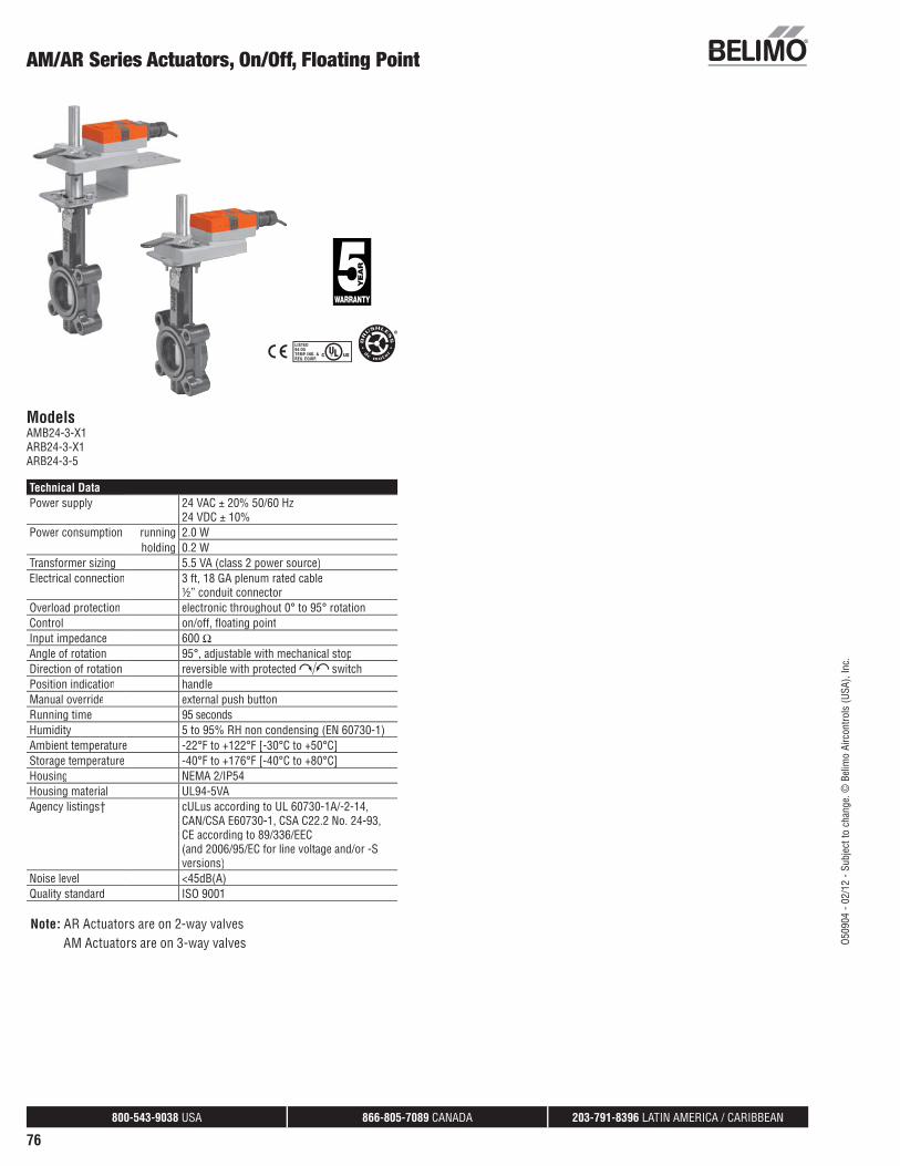
800-543-9038 USA 866-805-7089 CANADA 203-791-8396 LATIN AMERICA / CARIBBEAN
76
AM/AR Series Actuators, On/Off, Floating Point
ModelsAMB24-3-X1ARB24-3-X1ARB24-3-5
Technical DataPower supply 24 VAC ± 20% 50/60 Hz
24 VDC ± 10%Power consumption running 2.0 W
holding 0.2 WTransformer sizing 5.5 VA (class 2 power source)Electrical connection 3 ft, 18 GA plenum rated cable
½” conduit connectorOverload protection electronic throughout 0° to 95° rotationControl on/off, fl oating pointInput impedance 600 ΩAngle of rotation 95°, adjustable with mechanical stopDirection of rotation reversible with protected switchPosition indication handleManual override external push buttonRunning time 95 secondsHumidity 5 to 95% RH non condensing (EN 60730-1)Ambient temperature -22°F to +122°F [-30°C to +50°C]Storage temperature -40°F to +176°F [-40°C to +80°C]Housing NEMA 2/IP54Housing material UL94-5VAAgency listings† cULus according to UL 60730-1A/-2-14,
CAN/CSA E60730-1, CSA C22.2 No. 24-93,CE according to 89/336/EEC(and 2006/95/EC for line voltage and/or -S versions)
Noise level <45dB(A)Quality standard ISO 9001
Note: AR Actuators are on 2-way valves AM Actuators are on 3-way valves O5
0904
- 02
/12
- Sub
ject
to c
hang
e. ©
Bel
imo
Airc
ontro
ls (U
SA),
Inc.

800-543-9038 USA 866-805-7089 CANADA 203-791-8396 LATIN AMERICA / CARIBBEAN
77
Wiring Diagrams
2 CAUTION Equipment damage!Actuators may be connected in parallel.Power consumption and input impedance must be observed.
4 Actuators may also be powered by 24 VDC.
Meets cULus or UL and CSA requirements without theneed of an electrical ground connection.
WARNING Live Electrical Components! During installation, testing, servicing and troubleshooting of this product, it may
be necessary to work with live electrical components. Have a qualifi ed licensed electricianor other individual who has been properly trained in handling live electrical componentsperform these tasks. Failure to follow all electrical safety precautions when exposed to liveelectrical components could result in death or serious injury.
AM/AR Series Actuators, On/Off, Floating Point
j y
2 3 524 VAC Transformer
a opena closed
Blk (1) Common
Red (2) +
Wht (3) +a
LineVolts
The indication of direction is valid for switch position 1. AMB24-3-X1
1 0
W55
7_10
On/Off control
24 VAC Transformer
Blk (1) Common
Red (2) +
Wht (3) +
LineVolts
The indication of direction is valid for switch position 1.
2 3 5
AMB24-3-X1
1 0
W55
7_10
Floating Point or On/Off control
O509
04 -
02/1
2 - S
ubje
ct to
cha
nge.
© B
elim
o Ai
rcon
trols
(USA
), In
c.

800-543-9038 USA 866-805-7089 CANADA 203-791-8396 LATIN AMERICA / CARIBBEAN
78
ModelsAMX24-MFT-X1ARX24-MFT-X1ARB24-MFT-5
Technical DataPower supply 24 VAC ± 20% 50/60 Hz
24 VDC ± 10%Power consumption
running 4 Wholding 1.25 W
Transformer sizing 6 VA (class 2 power source)Electrical connection 3 ft [1m], 10 ft [3m], 16 ft [5m]
18 GA plenum rated cable½” conduit connector
Overload protection electronic throughout 0° to 95° rotationOperating range Y 2 to 10 VDC, 4 to 20 mA (default)
variable (VDC, PWM, fl oating point, on/off)Input impedance 100k Ω (0.1 mA), 500 Ω
1500 Ω (PWM, fl oating point, on/off)Feedback output U 2 to 10 VDC, 0.5 mA max
VDC variableAngle of rotation 95° electronically variableDirection of rotation reversible with protected switchPosition indication handleManual override external push buttonRunning time 150 seconds (default)
variable (90 to 350 secs)Humidity 5 to 95% RH non condensing
(EN 60730-1)Ambient temperature -22°F to +122°F [-30°C to +50°C]Storage temperature -40°F to +176°F [-40°C to +80°C]Housing NEMA 2/IP54Housing material UL94-5VAAgency listings† cULus according to UL60730-1A/-2-14,
CAN/CSA E60730-1, CSA C22.2 No. 24-93,CE according to 89/336/EEC
Noise level <45dB(A)Quality standard ISO 9001† Rated impulse voltage 4kV, Control pollution degree 3, Type of action 1
AM/AR Series Actuators, Multi-Function Technology
O509
04 -
02/1
2 - S
ubje
ct to
cha
nge.
© B
elim
o Ai
rcon
trols
(USA
), In
c.

800-543-9038 USA 866-805-7089 CANADA 203-791-8396 LATIN AMERICA / CARIBBEAN
79
Wiring Diagrams
3 Actuators may also be powered by 24 VDC.
4Position feedback cannot be used with Triac sink controller.The actuator internal common reference is not compatible.
6Control signal may be pulsed from either the Hot (source)or the Common (sink) 24 VAC line.
8Contact closures A & B also can be triacs.A& B should both be closed for triac source and open for triac sink.
9For triac sink the common connection from the actuatormust be connected to the hot connection.
The ZG-R01 500 Ω resistor converts the 4 to 20 mA control signal to2 to 10 VDC, up to 2 actuators may be connected in parallel.
WARNING Live Electrical Components! During installation, testing, servicing and troubleshooting of this product, it may
be necessary to work with live electrical components. Have a qualifi ed licensed electricianor other individual who has been properly trained in handling live electrical componentsperform these tasks. Failure to follow all electrical safety precautions when exposed to live electrical components could result in death or serious injury.
AM/AR Series Actuators, Multi-Function Technology
Blk (1) Common
Red (2) Hot
Wht (3) Y Input
Org (5) U Output
LineVolts
24 VAC/DC Transformer
aPosition
Feedback VDC (+)
(–)
3
W55
8_Bu
tterf
ly
Two Position
CCW
CW
A B 5
CCW
CW
A B 5
Direction of rotation switch
LineVolts
2 to 10 VDCFeedback Signal
24 VAC Transformer
Blk (1) Common –
Red (2) Hot +
Wht (3) Y1 Input
Org (5) U Output 2 to 10V
Pnk (4) Y2 Input 8
3
A
B
9
10
11
W55
8_Bu
tterf
ly
Floating Point
7
Blk (1) Common
Red (2) + Hot
Wht (3) Y1 Input, 2 to 10V
Org (5) U Output, 2 to 10V
4 to 20 mAor
2 to 10 VDC
Control Signal
LineVolts
24 VAC Transformer
(+) (–)
Ω500Ω1/4 watt
3 5
CCW CW
W55
8_Bu
tterf
ly
VDC/4-20 mA
Blk (1) Common
Red (2) + Hot
Wht (3) Y Input
Org (5) U Output
LineVolts
24 VAC Transformer (AC only)
(+)
(–)
8
Position
Feedback VDC
W55
8_Bu
tterf
ly
PWM
O509
04 -
02/1
2 - S
ubje
ct to
cha
nge.
© B
elim
o Ai
rcon
trols
(USA
), In
c.

800-543-9038 USA 866-805-7089 CANADA 203-791-8396 LATIN AMERICA / CARIBBEAN
80
GM/GR Actuators, On/Off, Floating Point
ModelsGMB24-3-X1GRB24-3-X1GRB24-3-5GRB24-3-7
Technical DataPower supply 24 VAC ± 20% 50/60 Hz
24 VDC ± 10%Power consumption running 4.0 W
holding 2 WTransformer sizing 6 VA (class 2 power source)Electrical connection 3 ft, 18 GA appliance cable,
1/2” conduit connectorOverload protection electronic throughout 0 to 95° rotationControl signal On/Off, Floating PointInput impedance 600 ΩAngle of rotation mechanically limited to 95°Direction of rotation reversible with switch A/BPosition indication 0 to 1 and reversible indicatorRunning time 150 sec.Humidity 5 to 95% RH non-condensingAmbient temperature -22°F to 122°F [-30°C to 50°C]Storage temperature -40°F to 176°F [-40°C to 80°C]Housing NEMA 2/IP54Housing material UL94-5VA (fl ammability rating)Agency listings cULus according to UL60730-1A/-2-14,
CAN/CSA E60730-1, CSA C22.2 No.24-93,CE according to 89/336/EEC
Noise level max. 45 dB (A)Servicing maintenance freeQuality standard ISO 9001
Note: GR Actuators are on 2-way valves GM Actuators are on 3-way valves
O509
04 -
02/1
2 - S
ubje
ct to
cha
nge.
© B
elim
o Ai
rcon
trols
(USA
), In
c.
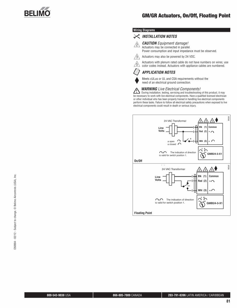
800-543-9038 USA 866-805-7089 CANADA 203-791-8396 LATIN AMERICA / CARIBBEAN
81
Wiring Diagrams
2 CAUTION Equipment damage!Actuators may be connected in parallel.Power consumption and input impedance must be observed.
3 Actuators may also be powered by 24 VDC.
5Actuators with plenum rated cable do not have numbers on wires; use color codes instead. Actuators with appliance cables are numbered.
Meets cULus or UL and CSA requirements without theneed of an electrical ground connection.
WARNING Live Electrical Components! During installation, testing, servicing and troubleshooting of this product, it may
be necessary to work with live electrical components. Have a qualifi ed licensed electricianor other individual who has been properly trained in handling live electrical componentsperform these tasks. Failure to follow all electrical safety precautions when exposed to liveelectrical components could result in death or serious injury.
GM/GR Actuators, On/Off, Floating Point
2 3 524 VAC Transformer
a opena closed
Blk (1) Common
Red (2) +
Wht (3) +a
LineVolts
The indication of direction is valid for switch position 1.
GMB24-3-X1
1 0
W55
9
On/Offj y
24 VAC Transformer
Blk (1) Common
Red (2) +
Wht (3) +
LineVolts
The indication of direction is valid for switch position 1.
2 3 5
GMB24-3-X1
1 0
W55
9
Floating Point
O509
04 -
02/1
2 - S
ubje
ct to
cha
nge.
© B
elim
o Ai
rcon
trols
(USA
), In
c.

800-543-9038 USA 866-805-7089 CANADA 203-791-8396 LATIN AMERICA / CARIBBEAN
82
ModelsGMX24-MFT-X1GRX24-MFT-X1GRB24-MFT-5GRX24-MFT-7
Technical DataPower supply 24 VAC ± 20% 50/60 Hz
24 VDC ± 10%Power consumption running 4.5 W
holding 2 WTransformer sizing 7 VA (class 2 power source)Electrical connection 3 ft, 18 GA appliance cable,
1/2” conduit connectorOverload protection electronic throughout 0 to 95° rotationControl signal 2 to 10 VDC, 4 to 20 mA
(with 500 Ω, 1/4 W resistor) ZG-R01Input impedance 100 k Ω for 2 to 10 VDC (0.1 mA)
500 Ω for 4 to 20 mA750 Ω for PWM1500 Ω for on/off and fl oating point
Angle of rotation mechanically limited to 95°Direction of rotation reversible with switch A/BPosition indication 0 to 1 and reversible indicatorRunning time 150 secondsHumidity 5 to 95% RH non-condensingAmbient temperature -22°F to 122°F [-30°C to 50°C]Storage temperature -40°F to 176°F [-40°C to 80°C]Housing NEMA 2/IP54Housing material UL94-5VA (fl ammability rating)Agency listings cULus according to UL60730-1A/-2-14,
CAN/CSA E60730-1, CSA C22.2 No.24-93,CE according to 89/336/EEC
Noise level max. 45 dB(A)Servicing maintenance freeQuality standard ISO 9001
GM/GR Actuators, Multi-Function Technology
O509
04 -
02/1
2 - S
ubje
ct to
cha
nge.
© B
elim
o Ai
rcon
trols
(USA
), In
c.

800-543-9038 USA 866-805-7089 CANADA 203-791-8396 LATIN AMERICA / CARIBBEAN
83
Wiring Diagrams
3 Actuators may also be powered by 24 VDC.
5Actuators with plenum rated cable do not have numbers on wires; use color coded instead. Actuators with appliance rated cable use numbers.
8Control signal may be pulsed from either the Hot (Source) orCommon (Sink) 24 VAC line.
10For triac sink the Common connection from the actuator must be connected to the Hot connection of the controller.
Meets cULus or UL and CSA requirements without theneed of an electrical ground connection.
9Contact closures A & B also can be triacs. A & B should both be closed for triac source and open for triac sink.
11Position feedback cannot be used with a Triac sink controller. The actuator internal common reference is not compatible.
WARNING Live Electrical Components! During installation, testing, servicing and troubleshooting of this product, it may
be necessary to work with live electrical components. Have a qualifi ed licensed electricianor other individual who has been properly trained in handling live electrical componentsperform these tasks. Failure to follow all electrical safety precautions when exposed to live electrical components could result in death or serious injury.
GM/GR Actuators, Multi-Function Technology
7
Blk (1) Common
Red (2) + Hot
Wht (3) Y1 Input, 2 to 10V
Org (5) U Output, 2 to 10V
4 to 20 mAor
2 to 10 VDC
Control Signal
LineVolts
24 VAC Transformer
(+) (–)
Ω500Ω1/4 watt
3 5
CCW CW
W54
5_No
_2
VDC/4-20 mA
Blk (1) Common
Red (2) Hot
Wht (3) Y Input
Org (5) U Output
LineVolts
24 VAC/DC Transformer
aPosition
Feedback VDC (+)
(–)
3
W54
5_No
_2
Two Position
CCW
CW
A B 5
CCW
CW
A B 5
Direction of rotation switch
LineVolts
2 to 10 VDCFeedback Signal
24 VAC Transformer
Blk (1) Common –
Red (2) Hot +
Wht (3) Y1 Input
Org (5) U Output 2 to 10V
Pnk (4) Y2 Input 8
3
A
B
9
10
11
W54
5_No
_2
Floating Point
Blk (1) Common
Red (2) + Hot
Wht (3) Y Input
Org (5) U Output
LineVolts
24 VAC Transformer (AC only)
(+)
(–)
8
Position
Feedback VDC
W54
5_No
_2PWM
Blk (1) Common
Red (2) + Hot
Wht (3) Y Input, 2 to 10 V
Org (5) U Output 2 to 10 V
CCW CW
Master
CCW CW
Slave
24 VAC Transformer
Line Volts
Control Signal 2 to 10 VDC
(–)(+)
3
5
Blk (1) Common
Red (2) + Hot
Wht (3) Y Input, 2 to 10 V
Org (5) U
5
Mas
ter_
Slav
e
Master/Slave
O509
04 -
02/1
2 - S
ubje
ct to
cha
nge.
© B
elim
o Ai
rcon
trols
(USA
), In
c.

800-543-9038 USA 866-805-7089 CANADA 203-791-8396 LATIN AMERICA / CARIBBEAN
84
ModelsGRCX24-3-T N4 w/terminal blockGRCB24-3-T N4H w/heater
Technical DataControl on/off, fl oating pointPower supply 24 VAC ± 20% 50/60 Hz
24 VDC ± 10%Power consumption running 8W / heater 29W
holding 2.5WTransformer sizing 11 VA (class 2 power source) / heater 26 VAElectrical connection screw terminal (for 22 to 12 AWG wire)Overload protection electronic throughout 0° to 90° rotationInput impedance 1000 Ω at control inputAngle of rotation 90°, adjustable with mechanical stopPosition indication visual pointerManual override internal push button (UL Type 4)Running time 35 seconds (default)Humidity 5 to 100% RH (UL Type 4)Ambient temperature -22°F to 122°F [-30°C to 50°C]Storage temperature -40°F to 176°F [-40°C to 80°C]Housing type UL Type 4/NEMA 4/IP66Housing material PolycarbonateAgency listings cULus according to UL 60730-1A, UL 60730-
2-14 and CAN/CSA E60730-1;Certifi ed to IEC/EN 60730-1 and IEC/EN 60730-2-14
EMC CE according to 2004/108/ECQuality standard ISO 9001
GRCX(B)24-3-T N4(H) NEMA 4 Actuators, On/Off, Floating Point
O509
04 -
02/1
2 - S
ubje
ct to
cha
nge.
© B
elim
o Ai
rcon
trols
(USA
), In
c.

800-543-9038 USA 866-805-7089 CANADA 203-791-8396 LATIN AMERICA / CARIBBEAN
85
GRCX(B)24-3-T N4(H) NEMA 4 Actuators, On/Off, Floating Point
Wiring Diagrams
2 CAUTION Equipment damage!Actuators may be connected in parallel.Power consumption and input impedance must be observed.
4 Actuators may also be powered by 24 VDC.
5Actuators with plenum rated cable do not have numbers on wires; use color codes instead. Actuators with appliance cables are numbered.
Meets cULus or UL and CSA requirements without theneed of an electrical ground connection. Use suitable fl exible metallicconduit or its equivalent with the conduit fi tting.
WARNING Live Electrical Components! During installation, testing, servicing and troubleshooting of this product,
it may be necessary to work with live electrical components. Have a qualifi ed li-censed electrician or other individual who has been properly trained in handlinglive electrical components perform these tasks. Failure to follow all electricalsafety precautions when exposed to live electrical components could result indeath or serious injury.
WARNING Mechanical Precautions The mechanical end stops cannot be moved or repositioned. Doing so
will adversely effect the operation of the valve.The directional switch cannot be moved. Maintain Factory Settings
On/Off Control
W39
9_10
Floating Point, AC Only
GRB24-3
GRB24-3
O509
04 -
02/1
2 - S
ubje
ct to
cha
nge.
© B
elim
o Ai
rcon
trols
(USA
), In
c.

800-543-9038 USA 866-805-7089 CANADA 203-791-8396 LATIN AMERICA / CARIBBEAN
86
ModelsGRX24-MFT-T N4 w/terminal blockGRB24-MFT-T N4H w/heater
Technical DataControl 2 to 10 VDC, 4 to 20 mA (default)
variable (VDC, fl oating point, on/off)Power supply 24 VAC ± 20% 50/60 Hz
24 VDC ± 10%Power consumption running 8 W / heater 29W
holding 2.5 W Transformer sizing 11 VA (class 2 power source) / heater 24 VAElectrical connection screw terminal (for 22 to 12 AWG wire)Overload protection electronic throughout 0° to 90° rotationInput impedance 100 kΩ for 2 to 10 VDC (0.1 mA)
500 Ω for 4 to 20 mA 1000 Ω for fl oating point and on-off control
Angle of rotation 90°, adjustable with mechanical stopelectronically variable
Position indication visual pointerManual override internal push button (UL Type 4)Running time 150 seconds (default)
variable (75 to 290 seconds)Humidity 5 to 100% RH (UL Type 4)Ambient temperature -22°F to 122°F [-30°C to 50°C]Storage temperature -40°F to 176°F [-40°C to 80°C]Housing type UL Type 4/NEMA 4/IP66Housing material PolycarbonateAgency listings cULus according to UL 60730-1A, UL 60730-
2-14 and CAN/CSA E60730-1;Certifi ed to IEC/EN 60730-1 and IEC/EN 60730-2-14
EMC CE according to 2004/108/ECQuality standard ISO 9001
GRX(B)24-MFT-T N4(H) NEMA 4 Actuators, Multi-Function Technology
O509
04 -
02/1
2 - S
ubje
ct to
cha
nge.
© B
elim
o Ai
rcon
trols
(USA
), In
c.

800-543-9038 USA 866-805-7089 CANADA 203-791-8396 LATIN AMERICA / CARIBBEAN
87
Wiring Diagrams
2 CAUTION Equipment damage!Actuators may be connected in parallel.Power consumption and input impedance must be observed.
3 Actuators may also be powered by 24 VDC.
5Actuators with plenum rated cable do not have numbers on wires; use color codes instead. Actuators with appliance cables are numbered.
8Control signal may be pulsed from either the Hot (source)or the Common (sink) 24 VAC line.
9Contact closures A & B also can be triacs.A& B should both be closed for triac source and open for triac sink.
10
For triac sink the Common connection from the actuator must be connected to the Hot connection of the controller. Position feedbackcannot be used with a Triac sink controller. The actuator internal common reference is not compatible.
12 IN4004 or IN4007 diode. (IN4007 supplied, Belimo part number 40155).
The ZG-R01 500 Ω resistor converts the 4 to 20 mA control signal to2 to 10 VDC, up to 2 actuators may be connected in parallel.
WARNING Live Electrical Components! During installation, testing, servicing and troubleshooting of this product,
it may be necessary to work with live electrical components. Have a qualifi ed li-censed electrician or other individual who has been properly trained in handlinglive electrical components perform these tasks. Failure to follow all electricalsafety precautions when exposed to live electrical components could result indeath or serious injury.
WARNING Mechanical Precautions The mechanical end stops cannot be moved or repositioned. Doing so
will adversely effect the operation of the valve.The directional switch cannot be moved. Maintain Factory Settings
GRX(B)24-MFT-T N4(H) NEMA 4 Actuators, Multi-Function Technology
W53
8
On/Off control
CCW CW
Line
Volts
(–) (+)
24 VAC Transformer
Blk (1) – Common
Red (2) + Hot
Wht (3) Y1 Input
(5) U Output 2 to 10V
A
B
2
9
8
10
12
Feedback Signal 2 to 10 VDC
5
Floating Point
W53
8
VDC/4-20 mA
...MFT...MFT
O509
04 -
02/1
2 - S
ubje
ct to
cha
nge.
© B
elim
o Ai
rcon
trols
(USA
), In
c.

800-543-9038 USA 866-805-7089 CANADA 203-791-8396 LATIN AMERICA / CARIBBEAN
88
ModelsGMCX24-3-T-X1 N4 w/terminal blockGMCB24-3-T-X1 N4H w/heater
Technical DataControl on/off, fl oating pointPower supply 24 VAC ± 20% 50/60 Hz
24 VDC ± 10%Power consumption running 8W / heater 28W
holding 2.5WTransformer sizing 11 VA (class 2 power source) / heater 26 VAElectrical connection screw terminal (for 22 to 12 AWG wire)Overload protection electronic throughout 0° to 95° rotationInput impedance 1000 Ω at control inputAngle of rotation 95°, adjustable with mechanical stop
electronically variableDirection of rotation reversible withPosition indication visual pointerManual override internal push button (UL Type 4)Running time 35 seconds (default)Humidity 5 to 100% RH (UL Type 4)Ambient temperature -22°F to 122°F [-30°C to 50°C]Storage temperature -40°F to 176°F [-40°C to 80°C]Housing type UL Type 4/NEMA 4/IP66Housing material PolycarbonateAgency listings cULus according to UL 60730-1A, UL
60730-2-14 and CAN/CSA E60730-1;Certifi ed to IEC/EN 60730-1 and IEC/EN 60730-2-14
EMC CE according to 2004/108/ECQuality standard ISO 9001
GMCX(B)24-3-T-X1 N4(H) NEMA 4 Actuators, On/Off, Floating Point
O509
04 -
02/1
2 - S
ubje
ct to
cha
nge.
© B
elim
o Ai
rcon
trols
(USA
), In
c.

800-543-9038 USA 866-805-7089 CANADA 203-791-8396 LATIN AMERICA / CARIBBEAN
89
GMCX(B)24-3-T-X1 N4(H) NEMA 4 Actuators, On/Off, Floating Point
Wiring Diagrams
2 CAUTION Equipment damage!Actuators may be connected in parallel.Power consumption and input impedance must be observed.
3 Actuators may also be powered by 24 VDC.
5Actuators with plenum rated cable do not have numbers on wires; use color codes instead. Actuators with appliance cables are numbered.
Meets cULus or UL and CSA requirements without theneed of an electrical ground connection.
WARNING Live Electrical Components! During installation, testing, servicing and troubleshooting of this product,
it may be necessary to work with live electrical components. Have a qualifi ed li-censed electrician or other individual who has been properly trained in handlinglive electrical components perform these tasks. Failure to follow all electricalsafety precautions when exposed to live electrical components could result indeath or serious injury.
2 3 524 VAC Transformer
a opena closed
Blk (1) Common
Red (2) +
Wht (3) +a
LineVolts
The indication of direction is valid for switch position 1.
GMB24-3-X1
1 0
W55
9
On/Offj y
24 VAC Transformer
Blk (1) Common
Red (2) +
Wht (3) +
LineVolts
The indication of direction is valid for switch position 1.
2 3 5
GMB24-3-X1
1 0
W55
9
Floating Point
O509
04 -
02/1
2 - S
ubje
ct to
cha
nge.
© B
elim
o Ai
rcon
trols
(USA
), In
c.

800-543-9038 USA 866-805-7089 CANADA 203-791-8396 LATIN AMERICA / CARIBBEAN
90
ModelsGMX24-MFT-T-X1 N4 w/terminal blockGMB24-MFT-T-X1 N4H w/heater
Technical DataControl 2 to 10 VDC, 4 to 20 mA (default)
variable (VDC, fl oating point, on/off)Power supply 24 VAC ± 20% 50/60 Hz
24 VDC ± 10%Power consumption running 8 W / heater 29W
holding 2.5 W Transformer sizing 11 VA (class 2 power source) / heater 26 VAElectrical connection screw terminal (for 22 to 12 AWG wire)Overload protection electronic throughout 0° to 95° rotationInput impedance 100 kΩ for 2 to 10 VDC (0.1 mA)
500 Ω for 4 to 20 mA 1000 Ω for fl oating point and on-off control
Angle of rotation 95°, adjustable with mechanical stopelectronically variable
Direction of rotation reversible withPosition indication visual pointerManual override internal push button (UL Type 4)Running time 150 seconds (default)
variable (75 to 290 seconds)Humidity 5 to 100% RH (UL Type 4)Ambient temperature -22°F to 122°F [-30°C to 50°C]Storage temperature -40°F to 176°F [-40°C to 80°C]Housing type UL Type 4/NEMA 4/IP66Housing material PolycarbonateAgency listings cULus according to UL 60730-1A, UL
60730-2-14 and CAN/CSA E60730-1;Certifi ed to IEC/EN 60730-1 and IEC/EN 60730-2-14
EMC CE according to 2004/108/ECQuality standard ISO 9001
GMX(B)24-MFT-T N4(H) NEMA 4 Actuators, Multi-Function Technology
O509
04 -
02/1
2 - S
ubje
ct to
cha
nge.
© B
elim
o Ai
rcon
trols
(USA
), In
c.

800-543-9038 USA 866-805-7089 CANADA 203-791-8396 LATIN AMERICA / CARIBBEAN
91
Wiring Diagrams
1 Provide overload protection and disconnect as required.
2 CAUTION Equipment Damage!NActuators may be connected in parallel if not mechanically mounted to the same shaft. Power consumption and input impedance must beobserved.
3 Actuators may also be powered by 24 VDC.
4Position feedback cannot be used with Triac sink controller.The actuator internal common reference is not compatible.
5Control signal may be pulsed from either the Hot (source)or the Common (sink) 24 VAC line.
GMX(B)24-MFT-T N4(H) NEMA 4 Actuators, Multi-Function Technology
8Contact closures A & B also can be triacs.A & B should both be closed for triac source and open for triac sink.
9For triac sink the common connection from the actuatormust be connected to the hot connection of the controller.
The ZG-R01 500 Ω resistor may be used.
WARNING Live Electrical Components! During installation, testing, servicing and troubleshooting of this product,
it may be necessary to work with live electrical components. Have a qualifi ed li-censed electrician or other individual who has been properly trained in handlinglive electrical components perform these tasks. Failure to follow all electricalsafety precautions when exposed to live electrical components could result indeath or serious injury.
C
W39
9_08
VDC/4-20 mA
W39
9_08
PWM
W39
9_08
On/Off control
W39
9_08
Floating Point controlroANADAANADA
Blk (1) Common
Red (2) + Hot
Wht (3) Y Input, 2 to 10 V
Org (5) U Output 2 to 10 V
CCW CW
Master
CCW CW
Slave
24 VAC Transformer
Line Volts
Control Signal 2 to 10 VDC
(–)(+)
3
5
Blk (1) Common
Red (2) + Hot
Wht (3) Y Input, 2 to 10 V
Org (5) U
5
Mas
ter_
Slav
e
Master/Slave
O509
04 -
02/1
2 - S
ubje
ct to
cha
nge.
© B
elim
o Ai
rcon
trols
(USA
), In
c.

Technical Data 307810
Power Supply 24...240 VAC, -20% / +10%, 50/60 Hz, 24...125 VDC, -20% / +10%
Power Consumption Running 20 W @ 24 V, 18 W @ 120 V, 20 W @ 230 VPower Consumption Holding 3.5 W @ 24 V, 4 W @ 120 V, 6 W @ 230 VTransformer Sizing 20 VA @ 24 VAC/DC (class 2 power source), 23
VA @ 120 VAC/DC, 52 VA @ 230 VACElectrical Connection terminal blockOverload Protection electronic thoughout 0° to 90° rotationOperating Range Y 2 to 10 VDC, 4 to 20 mA variable (VDC, floating
point, on/off)Input Impedance 100 k Ω for 2 to 10 VDC (0.1 mA), 500 Ω for 4
to 20 mA, 1500 Ω for On/OffFeedback Output U 2 to 10 VDC, 0.5 mA max, VDC variableAngle of Rotation 90°Torque motor Min. 1400 in-lbs [160 Nm]Direction of Rotation (Motor) reversible with appPosition Indication integral pointer and bottom mounted reflective
indicatorsManual Override 7 mm hex crank, suppliedRunning Time (Motor) 35 secAmbient Humidity 5 to 100% RH (UL Type 4)Ambient Temperature Range -22°F to 122°F [-30°C to 50°C]Storage Temperature Range -40°F to 176°F [-40°C to 80°C]Housing NEMA 4X, IP66/67, UL Enclosure Type 4Housing Material Aluminum die cast and plastic casingAgency Listings† cULus acc. to UL60730-1A/-2-14, CAN/CSA
E60730-1:02, CE acc. to 2004/108/EC and 2006/95/EC
Noise Level (Motor) 68 dB (A) Servicing maintenance freeQuality Standard ISO 9001Weight 12.8 lbs [5.8kg]Auxiliary switch 2 x SPDT, 3A resistive (0.5A inductive) @ 250
VAC, one set at 10°, one adjustable 0° to 90°Communication BACnet MS/TPPassive Sensor Inputs 2 (PT1000) (NI1000) (NTC)
ApplicationPR Series valve actuators are designed with an integrated linkage and visual position indicators. For outdoor applications, the installed valve must be mounted with the actuator at or above horizontal. For indoor applications the actuator can be in any location including directly under the valve.
OperationThe PR series actuator provides 90° of rotation and a visual indicator shows the position of the valve. The PR Series actuator uses a low power consumption brushless DC motor and is electronically protected against overload. A universal power supply is furnished to connect supply voltage in the range of 24-240 VAC and 24-125 VDC. Included is a smart heater with thermostat to eliminate condensation. Two auxiliary switches are provided; one set at 10° open and the other is field adjustable. Running time is field adjustable from 30-120 seconds by using the Near Field Communication (NFC) app and a smart phone.
†Use 60°C/75°C copper wire size range 12-28 AWG, stranded or solid. Use flexible metal conduit. Push the listed conduit fitting device over the actuator’s cable to butt against the enclosure. Screw in conduit connector. Jacket the actuators input wiring with listed flexible conduit. Properly terminate the conduit in a suitable junction box. Rated impulse Voltage 4000V. Type of action 1. Control pollution degree 3.
PRBUP-MFT-TModulating, Non-Spring Return, 24-240 V, NEMA 4X with BACnet
800-543-9038 USA 866-805-7089 CANADA 203-791-8396 LATIN AMERICA / CARIBBEAN
Date
cre
ated
, 11/
29/2
017
- Sub
ject
to c
hang
e. ©
Bel
imo
Airc
ontro
ls (U
SA),
Inc.

Wiring DiagramsMeets cULus requirements without the need of an electrical ground connection.
UP Universal Power Supply (UP) models can be supplied with 24 VAC up to 240 VAC, or 24 VDC up to 240 VDC.
Disconnect power.
Provide overload protection and disconnect as required.
Two built-in auxiliary switches (2x SPDT), for end position indication, interlock control, fan startup, etc.
Only connect common to negative (-) leg of control circuits.
46Actuators may be controlled in parallel. Current draw and input impedance must be observed.
! WARNING! LIVE ELECTRICAL COMPONENTS!During installation, testing, servicing and troubleshooting of this product, it may be necessary to work with live electrical components. Have a qualified licensed electrician or other individual who has been properly trained in handling live electrical components perform these tasks. Failure to follow all electrical safety precautions when exposed to live electrical components could result in death or serious injury.
N
L
Y1
Y2
Common
+ Hot
Input CCW (open)
Input CW (close)
24 to 240 VAC or
24 to 125 VDC
1UP 461!
On/Off
N
L
Y1
Y2
1UP 46!
Common
+ Hot
Input CCW (open)
Input CW (close)
24 to 240 VAC or
24 to 125 VDC
Floating Point
N
L
Y1
Y2
N
5UP 4624 to 240 VAC
or 24 to 125 VDC
-
+
Y3
U5
Com -
24 VDC Out (max 5mA)
Y3 0 - 10 VDC, 4-20 mA
U5/MP 0 - 10 VDC
1
Modulating
N
L
Y1
Y2
N
24 to 240 VACor
24 to 125 VDC
Com
D +
D -
Com
Bacnet D +
D -
BACnet
PRBUP-MFT-TModulating, Non-Spring Return, 24-240 V, NEMA 4X with BACnet
800-543-9038 USA 866-805-7089 CANADA 203-791-8396 LATIN AMERICA / CARIBBEAN
Date
cre
ated
, 11/
29/2
017
- Sub
ject
to c
hang
e. ©
Bel
imo
Airc
ontro
ls (U
SA),
Inc.

T1 Com
T1
T2 Com
T2
Temperature Sensors
0˚ to 90˚ default 85˚
41
Auxiliary Switches
PRBUP-MFT-TModulating, Non-Spring Return, 24-240 V, NEMA 4X with BACnet
800-543-9038 USA 866-805-7089 CANADA 203-791-8396 LATIN AMERICA / CARIBBEAN
Date
cre
ated
, 11/
29/2
017
- Sub
ject
to c
hang
e. ©
Bel
imo
Airc
ontro
ls (U
SA),
Inc.

Technical Data 287804
Power Supply 24...240 VAC, -20% / +10%, 50/60 Hz, 24...125 VDC, -20% / +10%
Power Consumption Running 20 W @ 24 V, 18 W @ 120 V, 20 W @ 230 VPower Consumption Holding 3.5 W @ 24 V, 4 W @ 120 V, 6 W @ 230 VTransformer Sizing 20 VA @ 24 VAC/DC (class 2 power source), 23
VA @ 120 VAC/DC, 52 VA @ 230 VACElectrical Connection terminal blockOverload Protection electronic thoughout 0° to 90° rotationInput Impedance 1000 ΩAngle of Rotation 90°Position Indication integral pointer and bottom mounted reflective
indicatorsManual Override 7 mm hex crank, suppliedRunning Time (Motor) 35 secAmbient Humidity 5 to 100% RH (UL Type 4)Ambient Temperature Range -22°F to 122°F [-30°C to 50°C]Housing NEMA 4X, IP66/67, UL Enclosure Type 4XHousing Material aluminum die cast polycarbonate coverAgency Listings† cULus acc. to UL60730-1A/-2-14, CAN/CSA
E60730-1:02, CE acc. to 2004/108/EC and 2006/95/EC
Noise Level (Motor) 68 dB (A) Servicing maintenance freeQuality Standard ISO 9001Weight 12.8 lbs [5.8kg]Auxiliary switch 2 x SPDT, 3A resistive (0.5A inductive) @ 250
VAC, one set at 10°, one adjustable 0° to 90°
ApplicationPR Series valve actuators are designed with an integrated linkage and visual position indicators. For outdoor applications, the installed valve must be mounted with the actuator at or above horizontal. For indoor applications the actuator can be in any location including directly under the valve.
OperationThe PR series actuator provides 90° of rotation and a visual indicator shows the position of the valve. The PR Series actuator uses a low power consumption brushless DC motor and is electronically protected against overload. A universal power supply is furnished to connect supply voltage in the range of 24-240 VAC and 24-125 VDC. Included is a smart heater with thermostat to eliminate condensation. Two auxiliary switches are provided; one set at 10° open and the other is field adjustable. Running time is field adjustable from 30-120 seconds by using the Near Field Communication (NFC) app and a smart phone.
†Use 60°C/75°C copper wire size range 12-28 AWG, stranded or solid. Use flexible metal conduit. Push the listed conduit fitting device over the actuator’s cable to butt against the enclosure. Screw in conduit connector. Jacket the actuators input wiring with listed flexible conduit. Properly terminate the conduit in a suitable junction box. Rated impulse Voltage 4000V. Type of action 1. Control pollution degree 3.
PRXUP-3-TOn/Off, Floating Point, Non-Spring Return, 24-240 V, NEMA 4X
800-543-9038 USA 866-805-7089 CANADA 203-791-8396 LATIN AMERICA / CARIBBEAN
Date
cre
ated
, 11/
29/2
017
- Sub
ject
to c
hang
e. ©
Bel
imo
Airc
ontro
ls (U
SA),
Inc.

Wiring DiagramsMeets cULus requirements without the need of an electrical ground connection.
UP Universal Power Supply (UP) models can be supplied with 24 VAC up to 240 VAC, or 24 VDC up to 125 VDC.
Disconnect power.
Provide overload protection and disconnect as required.
Two built-in auxiliary switches (2x SPDT), for end position indication, interlock control, fan startup, etc.
46Actuators may be controlled in parallel. Current draw and input impedance must be observed.
! WARNING! LIVE ELECTRICAL COMPONENTS!During installation, testing, servicing and troubleshooting of this product, it may be necessary to work with live electrical components. Have a qualified licensed electrician or other individual who has been properly trained in handling live electrical components perform these tasks. Failure to follow all electrical safety precautions when exposed to live electrical components could result in death or serious injury.
N
L
Y1
Y2
Common
+ Hot
Input CCW (open)
Input CW (close)
24 to 240 VAC or
24 to 125 VDC
1UP 461!
On/Off
N
L
Y1
Y2
1UP 46!
Common
+ Hot
Input CCW (open)
Input CW (close)
24 to 240 VAC or
24 to 125 VDC
Floating Point
0˚ to 90˚ default 85˚
41
Auxiliary Switches
PRXUP-3-TOn/Off, Floating Point, Non-Spring Return, 24-240 V, NEMA 4X
800-543-9038 USA 866-805-7089 CANADA 203-791-8396 LATIN AMERICA / CARIBBEAN
Date
cre
ated
, 11/
29/2
017
- Sub
ject
to c
hang
e. ©
Bel
imo
Airc
ontro
ls (U
SA),
Inc.

Technical Data 286809
Power Supply 24...240 VAC, -20% / +10%, 50/60 Hz, 24...125 VDC, -20% / +10%
Power Consumption Running 20 W @ 24 V, 18 W @ 120 V, 20 W @ 230 VPower Consumption Holding 3.5 W @ 24 V, 4 W @ 120 V, 6 W @ 230 VTransformer Sizing 20 VA @ 24 VAC/DC (class 2 power source), 23
VA @ 120 VAC/DC, 52 VA @ 230 VACElectrical Connection terminal blockOverload Protection electronic thoughout 0° to 90° rotationOperating Range Y 2 to 10 VDC, 4 to 20 mA variable (VDC, floating
point, on/off)Input Impedance 100 k Ω for 2 to 10 VDC (0.1 mA), 500 Ω for 4
to 20 mA, 1500 Ω for On/OffFeedback Output U 2 to 10 VDC, 0.5 mA max, VDC variableAngle of Rotation 90°Torque motor Min. 1400 in-lbs [160 Nm]Direction of Rotation (Motor) reversible with appPosition Indication integral pointer and bottom mounted reflective
indicatorsManual Override 7 mm hex crank, suppliedRunning Time (Motor) 35 secAmbient Humidity 5 to 100% RH (UL Type 4)Ambient Temperature Range -22°F to 122°F [-30°C to 50°C]Storage Temperature Range -40°F to 176°F [-40°C to 80°C]Housing NEMA 4X, IP66/67, UL Enclosure Type 4Housing Material Aluminum die cast and plastic casingAgency Listings† cULus acc. to UL60730-1A/-2-14, CAN/CSA
E60730-1:02, CE acc. to 2004/108/EC and 2006/95/EC
Noise Level (Motor) 68 dB (A) Servicing maintenance freeQuality Standard ISO 9001Weight 12.8 lbs [5.8kg]Auxiliary switch 2 x SPDT, 3A resistive (0.5A inductive) @ 250
VAC, one set at 10°, one adjustable 0° to 90°Communication BACnet MS/TPPassive Sensor Inputs 2 (PT1000) (NI1000) (NTC)
ApplicationPR Series valve actuators are designed with an integrated linkage and visual position indicators. For outdoor applications, the installed valve must be mounted with the actuator at or above horizontal. For indoor applications the actuator can be in any location including directly under the valve.
OperationThe PR series actuator provides 90° of rotation and a visual indicator shows the position of the valve. The PR Series actuator uses a low power consumption brushless DC motor and is electronically protected against overload. A universal power supply is furnished to connect supply voltage in the range of 24-240 VAC and 24-125 VDC. Included is a smart heater with thermostat to eliminate condensation. Two auxiliary switches are provided; one set at 10° open and the other is field adjustable. Running time is field adjustable from 30-120 seconds by using the Near Field Communication (NFC) app and a smart phone.
†Use 60°C/75°C copper wire size range 12-28 AWG, stranded or solid. Use flexible metal conduit. Push the listed conduit fitting device over the actuator’s cable to butt against the enclosure. Screw in conduit connector. Jacket the actuators input wiring with listed flexible conduit. Properly terminate the conduit in a suitable junction box. Rated impulse Voltage 4000V. Type of action 1. Control pollution degree 3.
PRXUP-MFT-TModulating, Non-Spring Return, 24-240 V, NEMA 4X with BACnet
800-543-9038 USA 866-805-7089 CANADA 203-791-8396 LATIN AMERICA / CARIBBEAN
Date
cre
ated
, 11/
29/2
017
- Sub
ject
to c
hang
e. ©
Bel
imo
Airc
ontro
ls (U
SA),
Inc.
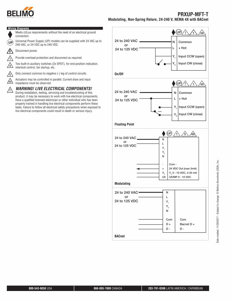
Wiring DiagramsMeets cULus requirements without the need of an electrical ground connection.
UP Universal Power Supply (UP) models can be supplied with 24 VAC up to 240 VAC, or 24 VDC up to 240 VDC.
Disconnect power.
Provide overload protection and disconnect as required.
Two built-in auxiliary switches (2x SPDT), for end position indication, interlock control, fan startup, etc.
Only connect common to negative (-) leg of control circuits.
46Actuators may be controlled in parallel. Current draw and input impedance must be observed.
! WARNING! LIVE ELECTRICAL COMPONENTS!During installation, testing, servicing and troubleshooting of this product, it may be necessary to work with live electrical components. Have a qualified licensed electrician or other individual who has been properly trained in handling live electrical components perform these tasks. Failure to follow all electrical safety precautions when exposed to live electrical components could result in death or serious injury.
N
L
Y1
Y2
Common
+ Hot
Input CCW (open)
Input CW (close)
24 to 240 VAC or
24 to 125 VDC
1UP 461!
On/Off
N
L
Y1
Y2
1UP 46!
Common
+ Hot
Input CCW (open)
Input CW (close)
24 to 240 VAC or
24 to 125 VDC
Floating Point
N
L
Y1
Y2
N
5UP 4624 to 240 VAC
or 24 to 125 VDC
-
+
Y3
U5
Com -
24 VDC Out (max 5mA)
Y3 0 - 10 VDC, 4-20 mA
U5/MP 0 - 10 VDC
1
Modulating
N
L
Y1
Y2
N
24 to 240 VACor
24 to 125 VDC
Com
D +
D -
Com
Bacnet D +
D -
BACnet
PRXUP-MFT-TModulating, Non-Spring Return, 24-240 V, NEMA 4X with BACnet
800-543-9038 USA 866-805-7089 CANADA 203-791-8396 LATIN AMERICA / CARIBBEAN
Date
cre
ated
, 11/
29/2
017
- Sub
ject
to c
hang
e. ©
Bel
imo
Airc
ontro
ls (U
SA),
Inc.

T1 Com
T1
T2 Com
T2
Temperature Sensors
0˚ to 90˚ default 85˚
41
Auxiliary Switches
PRXUP-MFT-TModulating, Non-Spring Return, 24-240 V, NEMA 4X with BACnet
800-543-9038 USA 866-805-7089 CANADA 203-791-8396 LATIN AMERICA / CARIBBEAN
Date
cre
ated
, 11/
29/2
017
- Sub
ject
to c
hang
e. ©
Bel
imo
Airc
ontro
ls (U
SA),
Inc.
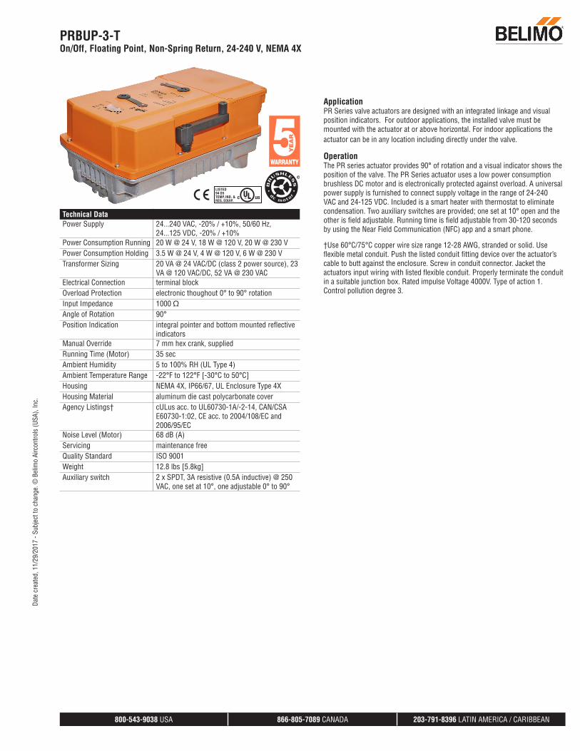
Technical Data 286808
Power Supply 24...240 VAC, -20% / +10%, 50/60 Hz, 24...125 VDC, -20% / +10%
Power Consumption Running 20 W @ 24 V, 18 W @ 120 V, 20 W @ 230 VPower Consumption Holding 3.5 W @ 24 V, 4 W @ 120 V, 6 W @ 230 VTransformer Sizing 20 VA @ 24 VAC/DC (class 2 power source), 23
VA @ 120 VAC/DC, 52 VA @ 230 VACElectrical Connection terminal blockOverload Protection electronic thoughout 0° to 90° rotationInput Impedance 1000 ΩAngle of Rotation 90°Position Indication integral pointer and bottom mounted reflective
indicatorsManual Override 7 mm hex crank, suppliedRunning Time (Motor) 35 secAmbient Humidity 5 to 100% RH (UL Type 4)Ambient Temperature Range -22°F to 122°F [-30°C to 50°C]Housing NEMA 4X, IP66/67, UL Enclosure Type 4XHousing Material aluminum die cast polycarbonate coverAgency Listings† cULus acc. to UL60730-1A/-2-14, CAN/CSA
E60730-1:02, CE acc. to 2004/108/EC and 2006/95/EC
Noise Level (Motor) 68 dB (A) Servicing maintenance freeQuality Standard ISO 9001Weight 12.8 lbs [5.8kg]Auxiliary switch 2 x SPDT, 3A resistive (0.5A inductive) @ 250
VAC, one set at 10°, one adjustable 0° to 90°
ApplicationPR Series valve actuators are designed with an integrated linkage and visual position indicators. For outdoor applications, the installed valve must be mounted with the actuator at or above horizontal. For indoor applications the actuator can be in any location including directly under the valve.
OperationThe PR series actuator provides 90° of rotation and a visual indicator shows the position of the valve. The PR Series actuator uses a low power consumption brushless DC motor and is electronically protected against overload. A universal power supply is furnished to connect supply voltage in the range of 24-240 VAC and 24-125 VDC. Included is a smart heater with thermostat to eliminate condensation. Two auxiliary switches are provided; one set at 10° open and the other is field adjustable. Running time is field adjustable from 30-120 seconds by using the Near Field Communication (NFC) app and a smart phone.
†Use 60°C/75°C copper wire size range 12-28 AWG, stranded or solid. Use flexible metal conduit. Push the listed conduit fitting device over the actuator’s cable to butt against the enclosure. Screw in conduit connector. Jacket the actuators input wiring with listed flexible conduit. Properly terminate the conduit in a suitable junction box. Rated impulse Voltage 4000V. Type of action 1. Control pollution degree 3.
PRBUP-3-TOn/Off, Floating Point, Non-Spring Return, 24-240 V, NEMA 4X
800-543-9038 USA 866-805-7089 CANADA 203-791-8396 LATIN AMERICA / CARIBBEAN
Date
cre
ated
, 11/
29/2
017
- Sub
ject
to c
hang
e. ©
Bel
imo
Airc
ontro
ls (U
SA),
Inc.

Wiring DiagramsMeets cULus requirements without the need of an electrical ground connection.
UP Universal Power Supply (UP) models can be supplied with 24 VAC up to 240 VAC, or 24 VDC up to 125 VDC.
Disconnect power.
Provide overload protection and disconnect as required.
Two built-in auxiliary switches (2x SPDT), for end position indication, interlock control, fan startup, etc.
46Actuators may be controlled in parallel. Current draw and input impedance must be observed.
! WARNING! LIVE ELECTRICAL COMPONENTS!During installation, testing, servicing and troubleshooting of this product, it may be necessary to work with live electrical components. Have a qualified licensed electrician or other individual who has been properly trained in handling live electrical components perform these tasks. Failure to follow all electrical safety precautions when exposed to live electrical components could result in death or serious injury.
N
L
Y1
Y2
Common
+ Hot
Input CCW (open)
Input CW (close)
24 to 240 VAC or
24 to 125 VDC
1UP 461!
On/Off
N
L
Y1
Y2
1UP 46!
Common
+ Hot
Input CCW (open)
Input CW (close)
24 to 240 VAC or
24 to 125 VDC
Floating Point
0˚ to 90˚ default 85˚
41
Auxiliary Switches
PRBUP-3-TOn/Off, Floating Point, Non-Spring Return, 24-240 V, NEMA 4X
800-543-9038 USA 866-805-7089 CANADA 203-791-8396 LATIN AMERICA / CARIBBEAN
Date
cre
ated
, 11/
29/2
017
- Sub
ject
to c
hang
e. ©
Bel
imo
Airc
ontro
ls (U
SA),
Inc.

Technical Data 303843
Power Supply 100-240 VAC ± 20%, 50/60 HzPower Consumption Running 4 W Power Consumption Holding 2 W Transformer Sizing 7 VA @ 24 VAC (class 2 power source)Electrical Connection 18 GA applicance rated cable with 1/2” conduit
connector protected NEMA 2 (IP54) 3 ft [1m] 10 ft [3m] and 16 ft [5m]
Overload Protection electronic throughout 0° to 95° rotationInput Impedance 600 ΩAngle of Rotation 90°, adjustable with mechanical stopDirection of Rotation (Motor) reversible with built-in switchManual Override external push buttonRunning Time (Motor) 150 secHumidity 5 to 95% RH non-condensingAmbient Temperature Range -22°F to +122°F [-30°C to +50°C]Storage Temperature Range -40°F to +176°F [-40°C to +80°C]Housing NEMA 2, IP42, UL enclosure type 2Housing Material UL94-5VAAgency Listings† cULus acc. to UL60730-1A/-2-14, CAN/CSA
E60730-1:02, CE acc. to 2004/108/EC and 2006/95/EC
Noise Level (Motor) <45 dB (A) Servicing maintenance freeQuality Standard ISO 9001Weight 3.5 lb [1.6 kg]
†Rated Impulse Voltage 800V, Type of action 1.AA, Control Pollution Degree 3
GRB120-3-5-14On/Off Floating Point, Non-Spring Return, 110 V
800-543-9038 USA 866-805-7089 CANADA 203-791-8396 LATIN AMERICA / CARIBBEAN
Date
cre
ated
, 09/
01/2
016
- Sub
ject
to c
hang
e. ©
Bel
imo
Airc
ontro
ls (U
SA),
Inc.

Wiring Diagrams
INSTALLATION NOTES
A Actuators with appliance cables are numbered.
Provide overload protection and disconnect as required.
Actuators may be connected in parallel if not mechanically linked. Power consumption and input impedance must be observed.
Meets cULus requirements without the need of an electrical ground connection.
! WARNING! LIVE ELECTRICAL COMPONENTS!During installation, testing, servicing and troubleshooting of this product, it may be necessary to work with live electrical components. Have a qualified licensed electrician or other individual who has been properly trained in handling live electrical components perform these tasks. Failure to follow all electrical safety precautions when exposed to live electrical components could result in death or serious injury.
Blu (1) Common
Brn (2) Load
Wht (3) Load
N
L
Line Wht
Volts Blk
A 1 11
On/Off 100 to 240 VAC
Blu (1) Common
Brn (2) Load
Wht (3) Load
Wht N
Blk L
LineVolts
A 1 11
Floating Point 100 to 240 VAC
GRB120-3-5-14On/Off Floating Point, Non-Spring Return, 110 V
800-543-9038 USA 866-805-7089 CANADA 203-791-8396 LATIN AMERICA / CARIBBEAN
Date
cre
ated
, 09/
01/2
016
- Sub
ject
to c
hang
e. ©
Bel
imo
Airc
ontro
ls (U
SA),
Inc.