f2000ex easy 02-24-00 ata 24 – electrical power …€¦ · · 2012-06-27gpu then it is...
TRANSCRIPT

F2000EX EASY 02-24-00
CODDE 1 PAGE 1 / 2
DGT94085
ATA 24 – ELECTRICAL POWER TABLE OF CONTENTS
ISSUE 3
DASSAULT AVIATION Proprietary Data
02-24 ATA 24 – ELECTRICAL POWER
02-24-00 TABLE OF CONTENTS
02-24-05 GENERAL
Introduction Sources Equipment location
02-24-10 DESCRIPTION
Generation Distribution Operation
02-24-15 CONTROL AND INDICATION
Control Indication
02-24-20 SYSTEM PROTECTION
Introduction Batteries Generators and APU Circuit breakers
02-24-25 NORMAL OPERATION
Introduction Ground operation with GPU plugged (MINI LOAD MASTER ON) Ground operation with APU operating (LH AV, RH AV and MINI LOAD MASTER ON) Normal flight operation
02-24-30 ABNORMAL OPERATION
Introduction BUS tieding and untieding policy Erroneous indication Battery 1 overheat GEN 2 failure CAS messages

02-24-00 F2000EX EASY
PAGE 2 / 2 CODDE 1
ISSUE 3
ATA 24 – ELECTRICAL POWER TABLE OF CONTENTS
DGT94085
DASSAULT AVIATION Proprietary Data
INTENTIONALLY LEFT BLANK

F2000EX EASY 02-24-05
CODDE 1 PAGE 1 / 4
DGT94085
ATA 24 – ELECTRICAL POWER GENERAL
ISSUE 3
DASSAULT AVIATION Proprietary Data
INTRODUCTION
The F2000EX EASy uses DC power for control, operation and indication of the various systems installed in the airplane.
The electrical power supply system consists of a 28 VDC on-board generation system designed to minimize electrical fluctuation and power interruption. It supplies, controls and distributes DC power to the on-board electrical equipment through three main buses (LH, ESS and RH buses).
Most of the avionics equipment is master switched on these respective buses: LH AV MASTER, MINI LOAD MASTER and RH AV MASTER.
The Median (MD) bus is used for liaison purpose.
The system is powered by two engine-driven generators and two batteries.
It can also be supplied by an Auxiliary Power Unit (APU) driven generator.
On ground, it can be supplied by an external DC Ground Power Unit (GPU).

02-24-05 F2000EX EASY
PAGE 2 / 4 CODDE 1
ISSUE 3
ATA 24 – ELECTRICAL POWER GENERAL
DGT94085
DASSAULT AVIATION Proprietary Data
DC supplyoverhead panel
Master switchesCircuit breakersoverhead panel
ELEC, STATand TESTsynoptics
CAS windows
FIGURE 02-24-05-00 FLIGHT DECK OVERVIEW

F2000EX EASY 02-24-05
CODDE 1 PAGE 3 / 4
DGT94085
ATA 24 – ELECTRICAL POWER GENERAL
ISSUE 3
DASSAULT AVIATION Proprietary Data
SOURCES
DC SOURCES AC SOURCES
INTERNAL
- two 36 Ah batteries
- two 12 kW engine-driven generators
- one 9 kW (300 A) APU-driven starter generator
- 1 Secondary Flight Display (SFD) battery: HORIZ BAT
- 1 auxiliary battery: AUX BAT (option)
- 3 batteries for the emergency lighting system
- 4 buffer batteries for LH DU, UP DU, MAU1 and MAU2.
- 4 NIC batteries, one batterie per NIC/PROC module of each channel of MAU.
- equipment requiring alternating current is equipped with built-in inverters
- passenger convenience items can be powered by inverters on a dedicated network
EXTERNAL - Ground Power Unit (GPU)

02-24-05 F2000EX EASY
PAGE 4 / 4 CODDE 1
ISSUE 3
ATA 24 – ELECTRICAL POWER GENERAL
DGT94085
DASSAULT AVIATION Proprietary Data
EQUIPMENT LOCATION
FIGURE 02-24-05-01 EQUIPMENT LOCATION

F2000EX EASY 02-24-10
CODDE 1 PAGE 1 / 10
DGT94085
ATA 24 – ELECTRICAL POWER DESCRIPTION
ISSUE 3
DASSAULT AVIATION Proprietary Data
GENERATION
MAIN BATTERIES
On ground, two 24 V (36 Ah) Ni-Cad batteries provide the primary source of DC power to the entire distribution system prior to APU starting. The BAT 1 supplies electrical power for starting the APU. As soon as one generator is connected, batteries are reloading and flatten generator electrical spikes. They are also capable of an emergency in-flight source of power for a limited period if all engine-driven generators fail. In that case, battery autonomy would be around 78 min (including 5 troubleshooting minutes) with maximum load shedding. The batteries are located in the forward servicing compartment accessible through the forward servicing compartment door. The batteries are ventilated, on the ground, by a battery-powered blower and by aerodynamic air flow in flight. During ground operation, the battery blower is operational when the BAT 1 switch is on.
NOTE
Very low-charged batteries cannot be connected to the buses, as their contactors need at least 18 VDC to close.
OTHER BATTERIES
Three batteries supply the emergency lights. One HORIZ BAT battery supplies Secondary Flight Display (SFD) in case of loss of LH bus for approximately 2 h 40 min. One AUX BAT battery when installed, may supply dedicated equipment. Four MAU-DU BAT buffer batteries supply the LH DU, UP DU, MAU1 and MAU2 so as to prevent them from dimming when the APU starts due to voltage drop . One of these supplies the Centralized Maintenance Computer (CMC) during shutdown. Four NIC batteries supply the NIC/PROC module of each chanel of MAU. Except for the batteries of emergency lights and NIC/PROC module, all battery voltages are monitored and indicated in the TEST synoptic page. The batteries of emergency lights can be checked by a three-position OFF-ON-ARM EMERG LIGHTS switch located on the overhead panel.

02-24-10 F2000EX EASY
PAGE 2 / 10 CODDE 1
ISSUE 3
ATA 24 – ELECTRICAL POWER DESCRIPTION
DGT94085
DASSAULT AVIATION Proprietary Data
ENGINE-DRIVEN GENERATORS
Engine-driven rectifier alternators are driven by the accessory gear box of each engine. A shear shaft in the generator prevents damages to the accessory gearbox in case of generator seizure. A damper in the generator shaft prevents from vibrations. They are rated at 12 kW and regulated at 28.5 VDC by their associated Generator Control Unit (GCU).
APU GENERATOR
The Auxiliary Power Unit (APU) is equipped with a starter-generator. On ground, it is capable of power the entire DC electrical system, in addition to charging batteries. It is rated at 9 kW and regulated at 28.5 VDC by its associated GCU.
ENGINE-DRIVEN GCU
The two Generator Control Units (GCU) provide current and voltage control and protection for their associated generator:
- Control: the GCU regulates the voltage at 28.5 VDC. It monitors the output current in order to comply with peak power protection (above 400 A). It also provides generator output control in order to balance the voltage between several generators, when connected in parallel.
- Protection: the GCU automatically disconnects its associated generator after debounce when the electric load limit is reached or overvoltage.
APU-DRIVEN GCU
The APU Generator Control Units (GCU) provides current and voltage control and protection for its associated generator:
- Control: the GCU regulates the voltage at 28.5 VDC and monitors the output current to 300 A, with a maximum of 350 A for one minute. It also provides generator output control in order to balance the voltage between several generators, when connected in parallel.
- Protection: the GCU automatically disconnects the generator when the electric load limit is reached or overvoltage.
It also controls APU start sequence.
F2000EX EASY 02-24-10
CODDE 1 PAGE 3 / 10
DGT94085
ATA 24 – ELECTRICAL POWER DESCRIPTION
ISSUE 3
DASSAULT AVIATION Proprietary Data
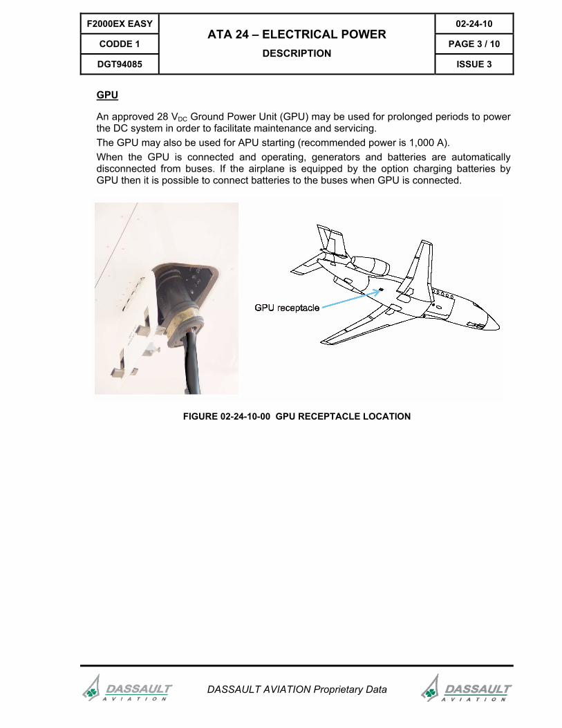
GPU
An approved 28 VDC Ground Power Unit (GPU) may be used for prolonged periods to power the DC system in order to facilitate maintenance and servicing. The GPU may also be used for APU starting (recommended power is 1,000 A). When the GPU is connected and operating, generators and batteries are automatically disconnected from buses. If the airplane is equipped by the option charging batteries by GPU then it is possible to connect batteries to the buses when GPU is connected.
FIGURE 02-24-10-00 GPU RECEPTACLE LOCATION

02-24-10 F2000EX EASY
PAGE 4 / 10 CODDE 1
ISSUE 3
ATA 24 – ELECTRICAL POWER DESCRIPTION
DGT94085
DASSAULT AVIATION Proprietary Data
DISTRIBUTION
GENERAL
DC power distribution is separated into three independent buses, allowing redundantly powered systems to continue to safely operate if one bus fails. The distribution system consists of 5 distinct buses:
- battery bus, - ESSential bus (A5, ESS), - MD bus (connects battery 2 to RH or ESS buses), - LH bus (A1, A2, A3, CABIN), - RH bus (B1, B2, B3, GALLEY).
FIGURE 02-24-10-01 ELECTRICAL SYSTEM DIAGRAM

F2000EX EASY 02-24-10
CODDE 1 PAGE 5 / 10
DGT94085
ATA 24 – ELECTRICAL POWER DESCRIPTION
ISSUE 3
DASSAULT AVIATION Proprietary Data
The battery bus is powered as soon as the battery 1 is installed and plugged in. Regardless of battery switch position, the battery bus provides electrical power directly to:
- the fueling panel, - the emergency slat control circuit, - the APU starter circuit, - the engine FIRE extinguishers secondary discharge, - the fuel shut-off valves, - LIGHT 1 and LIGHT 2, main access door, available if at least one of the five trip
magnetic switches is selected to on. Most of the avionics equipment is connected to the main buses through master-switches located on the overhead panel:
FIGURE 02-24-10-02 OVERHEAD PANEL

02-24-10 F2000EX EASY
PAGE 6 / 10 CODDE 1
ISSUE 3
ATA 24 – ELECTRICAL POWER DESCRIPTION
DGT94085
DASSAULT AVIATION Proprietary Data
LH BUS ESS BUS RH BUS
- ACP 3
- Data loader
- LSS (option)
- RAD ALT 1
- TCAS
- Weather Radar
- ADF 1
- ADM 1
- ATC 1
- CCD LH (one channel)
- CCD RH (one channel)
- DME 1
- GP LH
- LH DU
- MAU 2 channel B
- MKB LH
- UP DU
- VOR 1
- ADF 2
- ADM 2
- ATC 2
- AFCS channels A+B
- AP servomotors
- CCD LH (one channel)
- CCD RH (one channel)
- DME 2
- GP RH
- LW DU
- MAU 1 channel B
- MAU 2 channel A
- MKB RH
- RAD ALT 2
- RH DU
- VHF 3 (option)
- VOR 2
- Yaw Damper
F2000EX EASY 02-24-10
CODDE 1 PAGE 7 / 10
DGT94085
ATA 24 – ELECTRICAL POWER DESCRIPTION
ISSUE 3
DASSAULT AVIATION Proprietary Data
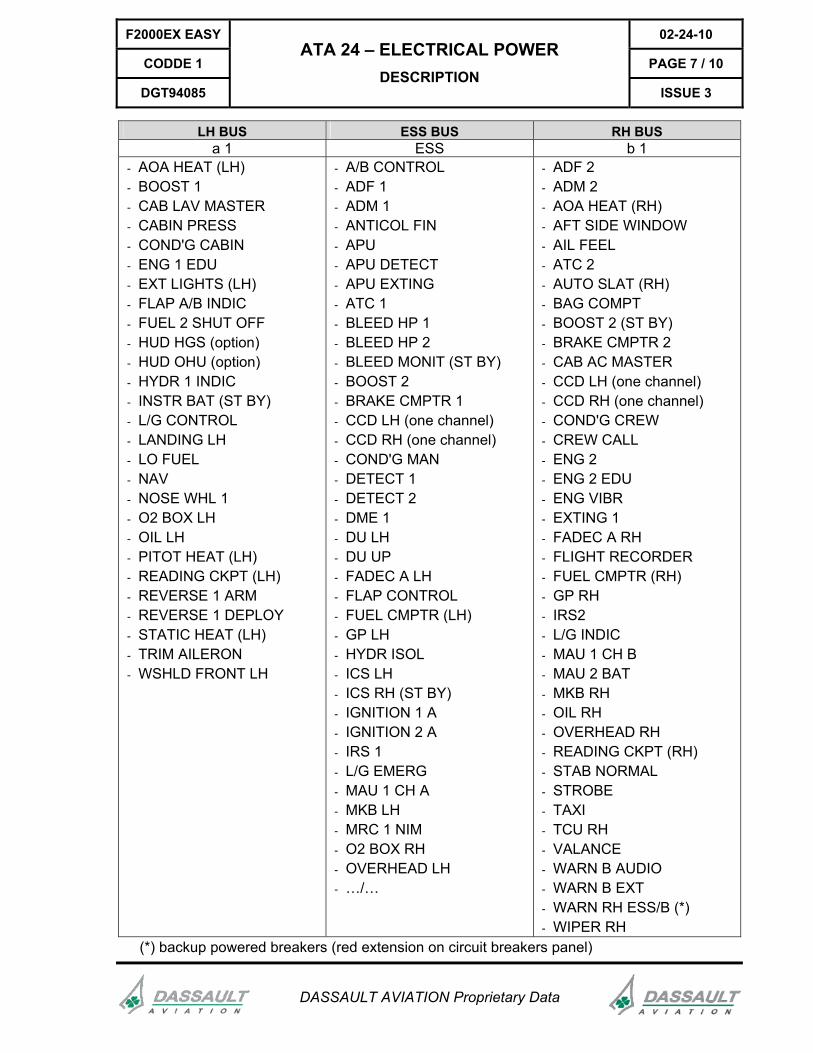
LH BUS ESS BUS RH BUS a 1 ESS b 1
- AOA HEAT (LH) - BOOST 1 - CAB LAV MASTER - CABIN PRESS - COND'G CABIN - ENG 1 EDU - EXT LIGHTS (LH) - FLAP A/B INDIC - FUEL 2 SHUT OFF - HUD HGS (option) - HUD OHU (option) - HYDR 1 INDIC - INSTR BAT (ST BY) - L/G CONTROL - LANDING LH - LO FUEL - NAV - NOSE WHL 1 - O2 BOX LH - OIL LH - PITOT HEAT (LH) - READING CKPT (LH) - REVERSE 1 ARM - REVERSE 1 DEPLOY - STATIC HEAT (LH) - TRIM AILERON - WSHLD FRONT LH
- A/B CONTROL - ADF 1 - ADM 1 - ANTICOL FIN - APU - APU DETECT - APU EXTING - ATC 1 - BLEED HP 1 - BLEED HP 2 - BLEED MONIT (ST BY) - BOOST 2 - BRAKE CMPTR 1 - CCD LH (one channel) - CCD RH (one channel) - COND'G MAN - DETECT 1 - DETECT 2 - DME 1 - DU LH - DU UP - FADEC A LH - FLAP CONTROL - FUEL CMPTR (LH) - GP LH - HYDR ISOL - ICS LH - ICS RH (ST BY) - IGNITION 1 A - IGNITION 2 A - IRS 1 - L/G EMERG - MAU 1 CH A - MKB LH - MRC 1 NIM - O2 BOX RH - OVERHEAD LH - …/…
- ADF 2 - ADM 2 - AOA HEAT (RH) - AFT SIDE WINDOW - AIL FEEL - ATC 2 - AUTO SLAT (RH) - BAG COMPT - BOOST 2 (ST BY) - BRAKE CMPTR 2 - CAB AC MASTER - CCD LH (one channel) - CCD RH (one channel) - COND'G CREW - CREW CALL - ENG 2 - ENG 2 EDU - ENG VIBR - EXTING 1 - FADEC A RH - FLIGHT RECORDER - FUEL CMPTR (RH) - GP RH - IRS2 - L/G INDIC - MAU 1 CH B - MAU 2 BAT - MKB RH - OIL RH - OVERHEAD RH - READING CKPT (RH) - STAB NORMAL - STROBE - TAXI - TCU RH - VALANCE - WARN B AUDIO - WARN B EXT - WARN RH ESS/B (*) - WIPER RH
(*) backup powered breakers (red extension on circuit breakers panel)
02-24-10 F2000EX EASY
PAGE 8 / 10 CODDE 1
ISSUE 3
ATA 24 – ELECTRICAL POWER DESCRIPTION
DGT94085
DASSAULT AVIATION Proprietary Data
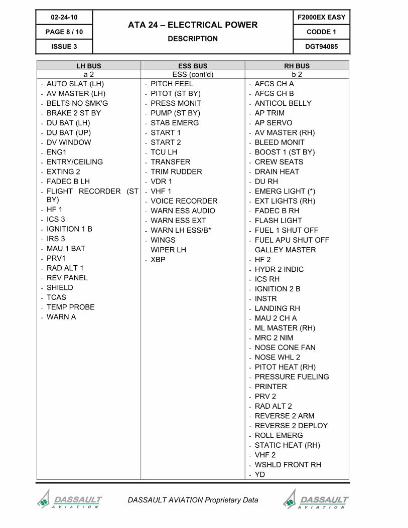
LH BUS ESS BUS RH BUS a 2 ESS (cont'd) b 2
- AUTO SLAT (LH) - AV MASTER (LH) - BELTS NO SMK'G - BRAKE 2 ST BY - DU BAT (LH) - DU BAT (UP) - DV WINDOW - ENG1 - ENTRY/CEILING - EXTING 2 - FADEC B LH - FLIGHT RECORDER (ST
BY) - HF 1 - ICS 3 - IGNITION 1 B - IRS 3 - MAU 1 BAT - PRV1 - RAD ALT 1 - REV PANEL - SHIELD - TCAS - TEMP PROBE - WARN A
- PITCH FEEL - PITOT (ST BY) - PRESS MONIT - PUMP (ST BY) - STAB EMERG - START 1 - START 2 - TCU LH - TRANSFER - TRIM RUDDER - VDR 1 - VHF 1 - VOICE RECORDER - WARN ESS AUDIO - WARN ESS EXT - WARN LH ESS/B* - WINGS - WIPER LH - XBP
- AFCS CH A - AFCS CH B - ANTICOL BELLY - AP TRIM - AP SERVO - AV MASTER (RH) - BLEED MONIT - BOOST 1 (ST BY) - CREW SEATS - DRAIN HEAT - DU RH - EMERG LIGHT (*) - EXT LIGHTS (RH) - FADEC B RH - FLASH LIGHT - FUEL 1 SHUT OFF - FUEL APU SHUT OFF - GALLEY MASTER - HF 2 - HYDR 2 INDIC - ICS RH - IGNITION 2 B - INSTR - LANDING RH - MAU 2 CH A - ML MASTER (RH) - MRC 2 NIM - NOSE CONE FAN - NOSE WHL 2 - PITOT HEAT (RH) - PRESSURE FUELING - PRINTER - PRV 2 - RAD ALT 2 - REVERSE 2 ARM - REVERSE 2 DEPLOY - ROLL EMERG - STATIC HEAT (RH) - VHF 2 - WSHLD FRONT RH - YD

F2000EX EASY 02-24-10
CODDE 1 PAGE 9 / 10
DGT94085
ATA 24 – ELECTRICAL POWER DESCRIPTION
ISSUE 3
DASSAULT AVIATION Proprietary Data
LH BUS ESS BUS RH BUS a 3 a 5 b 3
- WINDSHIELD (LH) - ST-BY PUMP - WINDSHIELD (RH)
a 4
- AC SYSTEM (option)
No breakers are connected to MD bus.
OPERATION
ON GROUND
When GPU is connected, all buses are automatically tied. RH and LH buses could be untied by selecting LH or RH ISOL pushbutton.
NORMAL FLIGHT
The bus tied rotary switch is in vertical position, ESS and MD buses are untied. RH and LH ISOL pushbuttons are set to tied (status light unlighted), LH bus is tied to ESS bus, RH buses tied to MD bus.
ABNORMAL CONDITIONS
In case of one generator failure, the battery supplies that bus.

02-24-10 F2000EX EASY
PAGE 10 / 10 CODDE 1
ISSUE 3
ATA 24 – ELECTRICAL POWER DESCRIPTION
DGT94085
DASSAULT AVIATION Proprietary Data
INTENTIONALLY LEFT BLANK

F2000EX EASY 02-24-15
CODDE 1 PAGE 1 / 12
DGT94085
ATA 24 – ELECTRICAL POWER CONTROL AND INDICATION
ISSUE 3
DASSAULT AVIATION Proprietary Data
CONTROL
FIGURE 02-24-15-00 OVERHEAD PANEL DURING NORMAL FLIGHT CONFIGURATION
SYNTHETIC TABLE
TO ACTIVATE CONTROL FUNCTION
TO DEACTIVATESYNOPTIC
On: contactor is closed
two-position trip magnetic
switch
Connected
Off: contactor is open and
engine stopped or GPU is On
two-position trip magnetic
switch
- GEN 1 connects generator 1 to the LH bus
- GEN 2 connects generator 2 to the RH bus
- trip automatically to down position when the GCU detects an anomaly (over voltage, over current)
- act as reset switches when the fault is cleared (only one reset attempt is allowed)
Disconnected
Abnormal situation:
contactor is open and engine is running and
there is no GPU
GEN1

02-24-15 F2000EX EASY
PAGE 2 / 12 CODDE 1
ISSUE 3
ATA 24 – ELECTRICAL POWER CONTROL AND INDICATION
DGT94085
DASSAULT AVIATION Proprietary Data
TO ACTIVATE
CONTROL FUNCTION TO DEACTIVATE
SYNOPTIC
- BAT 1 connects battery 1 to the ESS bus
Contactor closed and GPU is off
(except GPU-powered APU
starting)
BAT1
NOTE
Battery 1 supplies the battery bus whatever battery switch position
Contactor open and GPU is on (except during APU starting)
Connected
Abnormal situation:
contactor open without GPU
Abnormal situation:
contactor is closed and GPU is on
two-position trip magnetic
switch
two-position trip magnetic
switch
- BAT 2 connects battery 2 to the MD bus
- trip automatically to down position when the system detects an anomaly (high reverse current)
- act as reset switches when the fault is cleared
Disconnected
Abnormal situation:
overheating BAT1

F2000EX EASY 02-24-15
CODDE 1 PAGE 3 / 12
DGT94085
ATA 24 – ELECTRICAL POWER CONTROL AND INDICATION
ISSUE 3
DASSAULT AVIATION Proprietary Data
TO ACTIVATE
CONTROL FUNCTION TO DEACTIVATE
SYNOPTIC
contactor closed
(below
35,500 ft)
Connected
contactor closed
(above
35,500 ft)
contactor open (APU stopped or GPU is on)
two-position trip magnetic
switch
- connects the APU generator to the ESS bus
- trips automatically to down position when the GCU detects an over-voltage,
- acts as a reset switch when the fault is cleared (only one reset attempt is allowed)
Disconnected
Abnormal situation:
contactor open with APU
running and no GPU
Push On
On: airplane powered by
GPU on ground
light
pushbutton
ON GROUND ONLY:
- disconnects the batteries from their respective buses, independently from BAT magnetic switch position
- ties up all buses whatever BUS TIED rotary switch position
- allows GPU to supply all buses
Push Off
Off: airplane not powered by
GPU

02-24-15 F2000EX EASY
PAGE 4 / 12 CODDE 1
ISSUE 3
ATA 24 – ELECTRICAL POWER CONTROL AND INDICATION
DGT94085
DASSAULT AVIATION Proprietary Data
TO ACTIVATE
CONTROL FUNCTION TO DEACTIVATE
SYNOPTIC
Contactor
normally tied
Turn horizontally
Abnormally untied (rotary switch horizontal or
EXT POWER pushed on)
Contactor
normally untied
BUS TIED
rotary switch
- ties up ESS (left side) and MD (right side) buses
Turn
vertically
Abnormally tied (rotary switch
vertical with no GPU)
Contactor
closed
Push on Contactor
abnormally isolated
Contactor
normally isolated
- isolates LH bus from ESS bus or RH bus from MD bus
Push off
Contactor abnormally closed

F2000EX EASY 02-24-15
CODDE 1 PAGE 5 / 12
DGT94085
ATA 24 – ELECTRICAL POWER CONTROL AND INDICATION
ISSUE 3
DASSAULT AVIATION Proprietary Data
TO ACTIVATE CONTROL FUNCTION
TO DEACTIVATE SYNOPTIC
Push on (connected)
- sheds cabin optional equipment load from the LH bus
Push off (shed)
No specific indication on the ELEC synoptic
Push on (connected)
- supplies power to LH AV equipment
Push off (shed)
No specific indication on the ELEC synoptic
Push on (connected)
- supplies power to MINI LOAD equipment
Push off (shed)
No specific indication on the ELEC synoptic
Push on (connected)
- supplies power to RH AV equipment
Push off (shed)
No specific indication on the ELEC synoptic

02-24-15 F2000EX EASY
PAGE 6 / 12 CODDE 1
ISSUE 3
ATA 24 – ELECTRICAL POWER CONTROL AND INDICATION
DGT94085
DASSAULT AVIATION Proprietary Data
TO ACTIVATE
CONTROL FUNCTION TO DEACTIVATE
SYNOPTIC
Push on (connected)
- sheds galley equipment load from the RH bus
Push off (shed)
No specific indication on the ELEC synoptic
Switch
ARM
(in flight normal
position)
Switch
ON
(test position)
switch
- ON: Illuminates EMERG lights and checks their three batteries
Switch
OFF
No specific indication on the ELEC synoptic

F2000EX EASY 02-24-15
CODDE 1 PAGE 7 / 12
DGT94085
ATA 24 – ELECTRICAL POWER CONTROL AND INDICATION
ISSUE 3
DASSAULT AVIATION Proprietary Data
INDICATION
Electrical system indications are displayed on two pages on the MDU:
- ELEC synoptic,
- STAT synoptic.
FIGURE 02-24-15-01 ELECTRICAL SYNOPTIC

02-24-15 F2000EX EASY
PAGE 8 / 12 CODDE 1
ISSUE 3
ATA 24 – ELECTRICAL POWER CONTROL AND INDICATION
DGT94085
DASSAULT AVIATION Proprietary Data
EXAMPLES OF BATTERY TEMPERATURE INDICATION
Warm temperature:indication displayed
on amber background
Invalid dataHot temperature:indication displayedon red background
FIGURE 02-24-15-02 BATTERY TEMPERATURE INDICATION
For each battery, temperature indication is given by the pointer position on an analog scale and by digital readout. When the airplane is not equipped with temperature control (lead acid batteries), none of the above symbols and indication are displayed (option). The scale is colored in white below 49°C, in amber between 49°C and 71°C and in red above 71°C.
EXAMPLES OF BATTERY AMMETER
Normal valuesdisplayed in green
Abnormal valuesdisplayed in amber
Invalid data
FIGURE 02-24-15-03 BATTERY AMMETER
For each battery, current indication is given by the pointer position on an analog scale and by digital readout. The scale is colored in amber below – 300 A and, when APU is not starting, above + 45 A ; otherwise in white.
NOTE
A negative current designates a charging current.

F2000EX EASY 02-24-15
CODDE 1 PAGE 9 / 12
DGT94085
ATA 24 – ELECTRICAL POWER CONTROL AND INDICATION
ISSUE 3
DASSAULT AVIATION Proprietary Data
EXAMPLES OF DC GENERATOR AMMETER
Normal valuesdisplayed in green
Abnormal valuesdisplayed in amber
Invalid data
FIGURE 02-24-15-04 DC GENERATOR AMMETER
NOTE
For any generator or battery, 0 A is displayed on synoptic ammeters when actual current is between - 10 A and + 10 A.
Current indication is displayed by the pointer position on an analog scale and by digital readout. For both engine-driven generators, indication is permanent and the scale is colored in amber:
- on ground, above 300 A, - in flight, above 400 A.
For the APU generator, the ammeter is displayed in grey when the APU MASTER pushbutton is ON. Then, above 99% APU N1, the colored indication is displayed. Amber limitations are displayed:
- up to 10,000 ft, above 300 A, - between 10,000 ft and 25,000 ft, above 250 A, - above 25,000 ft, above 200 A.

02-24-15 F2000EX EASY
PAGE 10 / 12 CODDE 1
ISSUE 3
ATA 24 – ELECTRICAL POWER CONTROL AND INDICATION
DGT94085
DASSAULT AVIATION Proprietary Data
EXTERNAL POWER AMMETER
Normal valuesdisplayed in green
Abnormal valuesdisplayed in amber
Invalid data
FIGURE 02-24-15-05 DC EXTERNAL POWER AMMETER
For the external power ammeter, current indication is displayed on a digital readout when, on ground, EXT POWER light pushbutton is pushed on. The green display turns amber if current exceeds 300 A, except during GPU-powered APU starting (thresholds are modified with GPU batteries charging option).
STARTING PHASE
White START is placed under the APU ammeter during APU start. Amber START is placed under the APU in case of abnormal electric power supply.
FIGURE 02-24-15-06 STARTING PHASE
During the APU starting phase, the battery color code of the ELEC synoptic is specific:
- , BAT 1 contactor opens during APU start, whenever another electrical power is connected to buses (though contactor is open, ammeter deviates during APU start) and GPU is not connected. The symbol turns amber to indicate abnormal closed contactor.

F2000EX EASY 02-24-15
CODDE 1 PAGE 11 / 12
DGT94085
ATA 24 – ELECTRICAL POWER CONTROL AND INDICATION
ISSUE 3
DASSAULT AVIATION Proprietary Data
- BAT1 , BAT 1 contactor closes if none electrical power is connected or during GPU assisted APU start. The symbol turns amber to indicate abnormal open contactor.
- , BAT 2 contactor opens during APU start. The symbol turns amber to indicate abnormal closed contactor.
EXAMPLES OF LH AND RH BUSES VOLTMETER
Normal valuesdisplayed in green
Abnormal valuesdisplayed in amber
Invalid data
FIGURE 02-24-15-07 BUSES VOLTMETER
LH and RH buses are permanently monitored through two voltmeters displayed in the synoptic page. The ESS bus voltmeter is displayed when essential and LH buses are untied. The MD bus voltmeter is displayed when MD bus (and its battery 2) is isolated from both ESS and RH buses. When a generator supplies the bus, the range of the analog scale is colored in amber below 25 V and above 30 V. This range is different in case of other electric configuration (bus supplied by batteries only, APU starting, …).
NOTE
Electrical information is also available on the STAT synoptic.

02-24-15 F2000EX EASY
PAGE 12 / 12 CODDE 1
ISSUE 3
ATA 24 – ELECTRICAL POWER CONTROL AND INDICATION
DGT94085
DASSAULT AVIATION Proprietary Data
STATUS SYNOPTIC
System failure area Failure consequence area
Buses voltageandgeneratorscurrentindications
FIGURE 02-24-15-08 STATUS SYNOPTIC
TEST SYNOPTIC
FIGURE 02-24-15-09 TEST SYNOPTIC
To check MAU / DU BAT or HORIZ BAT, ..., place the CCD cursor on the respective soft key and keep the <enter> button pressed to have indications displayed. Normal values appear in green while too low or too high values appear in amber.

F2000EX EASY 02-24-20
CODDE 1 PAGE 1 / 4
DGT94085
ATA 24 – ELECTRICAL POWER SYSTEM PROTECTION
ISSUE 3
DASSAULT AVIATION Proprietary Data
INTRODUCTION
Feeder cables are protected by current fuses located inside the two main electrical boxes.
Circuit protection is provided by conventional trip-free circuit breakers located on the circuit breakers panel.
The circuit breakers panel is divided into different sections. Each section, delimited by different colored frames, corresponds to airplane major systems.
In case of failure of one engine-driven generator, certain items, not essential for the flight, are automatically load-shed.
The auto load-shed system is disabled when the airplane is on the ground, allowing normal operation of all cabin facilities.
The BUS TIED rotary switch normal flight position is vertical, isolating left side buses from right ones. In case of overvoltage or short-circuit on one side, the other side is not affected.
The ESS and MD buses can be temporary tied, for ground operations with no engine-driven generator assistance for example.
When ESS and MD buses are tied, the contactor provides protection between them in case of overload on one side.
BATTERIES
The batteries are protected against excessive load by a trip magnetic switch, which opens and disconnects the battery when the charging (reverse) current exceeds 330 A for more than 3 sec.
The BAT magnetic switch trips off and BAT .. CAS message appears.
NOTE
Only two reset attempts permitted.
Batteries are ventilated on ground and in flight to protect them (hydrogen accumulation, heating). On ground, the ventilation by an electrical blower is operational when the BAT 1 trip magnetic switch is up and the position of the EXT POWER pushbutton is off. In flight, ventilation is provided by the effect of dynamic air flowing through a venting duct and blowing on the batteries.

02-24-20 F2000EX EASY
PAGE 2 / 4 CODDE 1
ISSUE 3
ATA 24 – ELECTRICAL POWER SYSTEM PROTECTION
DGT94085
DASSAULT AVIATION Proprietary Data
GENERATORS AND APU
The engine-driven generators and the APU are each monitored by a GCU.
Main protections are:
- voltage control (at 28.5 VDC) and protection,
- electric load protection,
- reverse current, ...
The magnetic switch may trip off the corresponding generator.
GEN .. CAS message will appear.
CIRCUIT BREAKERS
FIGURE 02-24-20-00 CIRCUIT BREAKERS PANEL

F2000EX EASY 02-24-20
CODDE 1 PAGE 3 / 4
DGT94085
ATA 24 – ELECTRICAL POWER SYSTEM PROTECTION
ISSUE 3
DASSAULT AVIATION Proprietary Data
CIRCUIT BREAKER COLOR CODE
ESS BUS
A1 and A2 BUS
B1 and B2 BUS
EMERG LIGHTS WARNING RH ESS / B WARNING LH ESS / B
To be pulled if all generators fail
NOTE
Red breakers are backup powered by another bus.

02-24-20 F2000EX EASY
PAGE 4 / 4 CODDE 1
ISSUE 3
ATA 24 – ELECTRICAL POWER SYSTEM PROTECTION
DGT94085
DASSAULT AVIATION Proprietary Data
INTENTIONALLY LEFT BLANK

F2000EX EASY 02-24-25
CODDE 1 PAGE 1 / 6
DGT94085
ATA 24 – ELECTRICAL POWER NORMAL OPERATION
ISSUE 3
DASSAULT AVIATION Proprietary Data
INTRODUCTION
In the following, typical ground and in-flight situations have been selected to help the crew to understand the symbols provided in the various panels and displays.

02-24-25 F2000EX EASY
PAGE 2 / 6 CODDE 1
ISSUE 3
ATA 24 – ELECTRICAL POWER NORMAL OPERATION
DGT94085
DASSAULT AVIATION Proprietary Data
GROUND OPERATION WITH GPU PLUGGED (MINI LOAD MASTER ON)
FIGURE 02-24-25-00 OVERHEAD PANEL DURING GPU OPERATION

F2000EX EASY 02-24-25
CODDE 1 PAGE 3 / 6
DGT94085
ATA 24 – ELECTRICAL POWER NORMAL OPERATION
ISSUE 3
DASSAULT AVIATION Proprietary Data
FIGURE 02-24-25-01 ELECTRICAL SYNOPTIC DURING GPU OPERATION
ACTION RESULT
Plug in the GPU which is not running. No result
Turn on GPU (at 28 VDC)
Push on EXT PWR light pushbutton
- green light on
- all MASTER: OFF lights on
Push on MINI LOAD MASTER
- MINI LOAD MASTER: OFF light off
- GPU ON: BUS TIED CAS message
- symbol
- all GEN and BAT isolated (grey synoptic symbols)
- BUS TIED amber indication
- LH and RH buses voltage indications

02-24-25 F2000EX EASY
PAGE 4 / 6 CODDE 1
ISSUE 3
ATA 24 – ELECTRICAL POWER NORMAL OPERATION
DGT94085
DASSAULT AVIATION Proprietary Data
GROUND OPERATION WITH APU OPERATING (LH AV, RH AV AND MINI LOAD MASTER ON)
FIGURE 02-24-25-02 OVERHEAD PANEL DURING APU OPERATION

F2000EX EASY 02-24-25
CODDE 1 PAGE 5 / 6
DGT94085
ATA 24 – ELECTRICAL POWER NORMAL OPERATION
ISSUE 3
DASSAULT AVIATION Proprietary Data
FIGURE 02-24-25-03 ELECTRICAL SYNOPTIC DURING APU OPERATION
ACTION RESULT
BAT overhead panel trip magnetic switches up position No result
MINI LOAD MASTER overhead panel pushbutton pushed on
- BAT symbols in green
- LH and RH buses voltage indications
- GEN in stand-by + symbol in grey
BUS TIED rotary switch in horizontal position
- BUS TIED contactor symbol in green, closed
- BUS TIED amber indication on the ELEC synoptic
APU starting procedure - APU synoptic symbol in green when
connected to ESS bus
LH and RH AV MASTER overhead panel pushbuttons pushed on
- LH and RH AV MASTER: OFF lights off

02-24-25 F2000EX EASY
PAGE 6 / 6 CODDE 1
ISSUE 3
ATA 24 – ELECTRICAL POWER NORMAL OPERATION
DGT94085
DASSAULT AVIATION Proprietary Data
NORMAL FLIGHT OPERATION
FIGURE 02-24-25-04 OVERHEAD PANEL DURING NORMAL FLIGHT OPERATION
FIGURE 02-24-25-05 ELECTRICAL SYNOPTIC DURING NORMAL FLIGHT OPERATION

F2000EX EASY 02-24-30
CODDE 1 PAGE 1 / 10
DGT94085
ATA 24 – ELECTRICAL POWER ABNORMAL OPERATION
ISSUE 3
DASSAULT AVIATION Proprietary Data
INTRODUCTION
In the following, typical abnormal situations have been selected to help the crew to understand the symbols provided in the various panels and displays.
BUS TIEDING AND UNTIEDING POLICY
NORMAL FLIGHT CONDITION
FIGURE 02-24-30-00 NORMAL FLIGHT CONDITION
- GEN 1 and BAT 1 supply LH and ESS coupled buses, - GEN 2 and BAT 2 supply RH and MD coupled buses.
GENERATOR FAILURE
- At GEN 1 failure (or engine 1), LH bus is maintained coupled to ESS bus, - All the equipment supplied by LH bus and ESS bus are available.
FIGURE 02-24-30-01 GENERATOR FAILURE WITH SLATS EXTENDED
the ESS and MD buses must be tied via the bus tied rotary switch.
FIGURE 02-24-30-02 BUS TIED
- GEN 2, BAT 1 and BAT 2 (eventually APU as required) supply the four buses.

02-24-30 F2000EX EASY
PAGE 2 / 10 CODDE 1
ISSUE 3
ATA 24 – ELECTRICAL POWER ABNORMAL OPERATION
DGT94085
DASSAULT AVIATION Proprietary Data
SECOND GENERATOR FAILURE
FIGURE 02-24-30-03 ONE GEN FAILED
At second generator failure : - LH bus is automatically isolated from ESS bus, :
o LH ISOL status light displayed, - RH bus is automatically isolated from MD bus:
o RH ISOL status light displayed.
FIGURE 02-24-30-04 SECOND GENERATOR FAILURE
BAT 1 and BAT 2 (eventually APU as required) supply ESS and MD buses.
BATTERY 1 OVERHEAT
ABNORMAL STATUS
FIGURE 02-24-30-05 OVERHEAD PANEL DURING BAT 1 OVERHEAT

F2000EX EASY 02-24-30
CODDE 1 PAGE 3 / 10
DGT94085
ATA 24 – ELECTRICAL POWER ABNORMAL OPERATION
ISSUE 3
DASSAULT AVIATION Proprietary Data
FIGURE 02-24-30-06 ELECTRICAL SYNOPTIC DURING BAT 1 OVERHEAT
CONTEXT RESULT
- Battery 1 overheat
- HOT BAT 1 CAS message
Battery temperature > 71.1°C (160°F)
- MASTER
WARNING light on
- ELEC synoptic: BAT 1 symbol in red +
BAT 1 temperature indication in red

02-24-30 F2000EX EASY
PAGE 4 / 10 CODDE 1
ISSUE 3
ATA 24 – ELECTRICAL POWER ABNORMAL OPERATION
DGT94085
DASSAULT AVIATION Proprietary Data
AFTER PROCEDURE COMPLETE
FIGURE 02-24-30-07 OVERHEAD PANEL AFTER BAT 1 SWITCHED OFF
F2000EX EASY 02-24-30
CODDE 1 PAGE 5 / 10
DGT94085
ATA 24 – ELECTRICAL POWER ABNORMAL OPERATION
ISSUE 3
DASSAULT AVIATION Proprietary Data
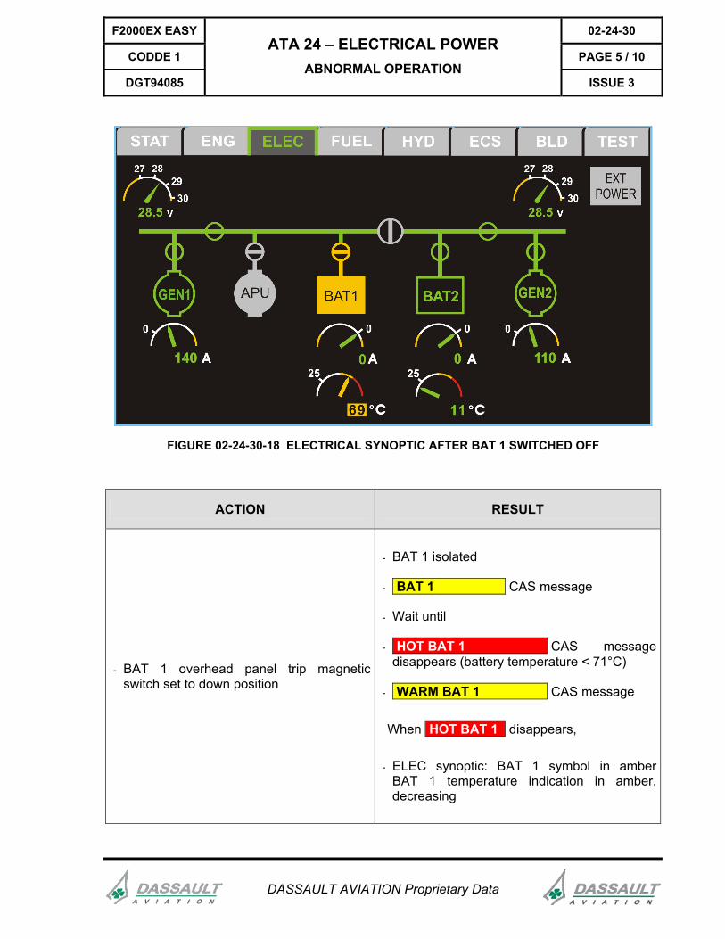
FIGURE 02-24-30-18 ELECTRICAL SYNOPTIC AFTER BAT 1 SWITCHED OFF
ACTION RESULT
- BAT 1 overhead panel trip magnetic switch set to down position
- BAT 1 isolated
- BAT 1 CAS message
- Wait until
- HOT BAT 1 CAS message disappears (battery temperature < 71°C)
- WARM BAT 1 CAS message
When HOT BAT 1 disappears,
- ELEC synoptic: BAT 1 symbol in amberBAT 1 temperature indication in amber, decreasing

02-24-30 F2000EX EASY
PAGE 6 / 10 CODDE 1
ISSUE 3
ATA 24 – ELECTRICAL POWER ABNORMAL OPERATION
DGT94085
DASSAULT AVIATION Proprietary Data
GEN 2 FAILURE
ABNORMAL STATUS
FIGURE 02-24-30-08 OVERHEAD PANEL DURING GEN 2 FAILURE
F2000EX EASY 02-24-30
CODDE 1 PAGE 7 / 10
DGT94085
ATA 24 – ELECTRICAL POWER ABNORMAL OPERATION
ISSUE 3
DASSAULT AVIATION Proprietary Data
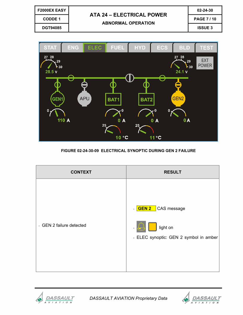
FIGURE 02-24-30-09 ELECTRICAL SYNOPTIC DURING GEN 2 FAILURE
CONTEXT RESULT
- GEN 2 failure detected
- GEN 2 CAS message
- light on
- ELEC synoptic: GEN 2 symbol in amber

02-24-30 F2000EX EASY
PAGE 8 / 10 CODDE 1
ISSUE 3
ATA 24 – ELECTRICAL POWER ABNORMAL OPERATION
DGT94085
DASSAULT AVIATION Proprietary Data
AFTER PROCEDURE COMPLETE
FIGURE 02-24-30-10 OVERHEAD PANEL WITH GEN 2 SWITCHED OFF AND BUS TIED

F2000EX EASY 02-24-30
CODDE 1 PAGE 9 / 10
DGT94085
ATA 24 – ELECTRICAL POWER ABNORMAL OPERATION
ISSUE 3
DASSAULT AVIATION Proprietary Data
FIGURE 02-24-30-11 ELECTRICAL SYNOPTIC WITH GEN 2 SWITCH TRIPPED OFF AND BUS TIED ON
ACTION RESULT
- GEN 2 overhead panel trip magnetic switch set to down position
- BUS TIED rotary switch set to tied position (horizontal position) - symbol on ELEC synoptic
- RH ISOL pushbutton depressed - symbol on ELEC synoptic
- RH ISOL status light off
- BUS RH TIED and GEN 2 CAS messages

02-24-30 F2000EX EASY
PAGE 10 / 10 CODDE 1
ISSUE 3
ATA 24 – ELECTRICAL POWER ABNORMAL OPERATION
DGT94085
DASSAULT AVIATION Proprietary Data
CAS MESSAGES
CAS MESSAGE DEFINITION
2 GEN’S FAIL The two electrical generator connections have failed and at least one engine is running
HOT BAT .. Temperature of one battery above 71°C (160°F)
APU GEN APU generator not connected with APU running
BAT .. Battery (1/2) contactor open (except during APU starting or GPU power supply)
BAT .. TEMP INOP Battery (1/2) temperature probe inoperative (on ground)
BUS ESSENTIAL LOW VOLTAGE Low voltage on essential bus
BUS ESSENTIAL OVERVOLTAGE Overvoltage on essential bus
BUS XX ISOL (LH/RH) ISOL bus contactor is open
BUS XX LOW VOLTAGE (LH/RH) bus voltage lower than 24 V with one generator connected
BUS XX OVERVOLTAGE (LH/RH) bus voltage above 32 V
BUS RH TIED BUS TIED contactor is tied while rotary switch is turned to untied, without GPU, RH ISOL is not pushed to ISOL
GEN .. One generator failed to connect though its engine is running, without GPU
OVHD BACKUP PWR LH+RH FAIL (LH/RH) backup power supply in overhead panel not operative on ground
STARTER APU APU on and its starter still active
WARM BAT .. Battery (1/2) temperature between 49°C (120°F) and 71°C
APU GEN FAIL On ground, APU contactor failed to open
BAT .. TEMP INOP Battery (1/2) temperature measurement invalid
BUS RH TIED BUS TIED contactor is tied with rotary switch turned to tied, without GPU, RH ISOL is not pushed to ISOL
GEN .. FAIL On ground, GEN (1/2) contactor failed to open without engine running or with GPU on
GPU ON: BUS TIED Airplane powered by GPU and bus tied is automatically tied.
OVHD BACKUP PWR XX FAIL (LH/RH) backup power supply for overhead panel fails