f1236720 dupont engineering polymers general design principles module i
TRANSCRIPT
7/23/2019 f1236720 DuPont Engineering Polymers General Design Principles Module I
http://slidepdf.com/reader/full/f1236720-dupont-engineering-polymers-general-design-principles-module-i 1/155
DuPont ™
Engineering Polymers
General Design Principles – Module I
® DuPont registered trademarks of E.I. du Pont de Nemours and Company
DuPont and The miracles of science ™ are trademarks of E.I. du Pont de Nemours and Company

7/23/2019 f1236720 DuPont Engineering Polymers General Design Principles Module I
http://slidepdf.com/reader/full/f1236720-dupont-engineering-polymers-general-design-principles-module-i 2/155
7/23/2019 f1236720 DuPont Engineering Polymers General Design Principles Module I
http://slidepdf.com/reader/full/f1236720-dupont-engineering-polymers-general-design-principles-module-i 3/155
Table of Contents1 General Page
Defining the End-Use Requirements . . . . . . . . . . . . . . 3Design Check List . . . . . . . . . . . . . . . . . . . . . . . . . . . . . 4Prototyping the Design . . . . . . . . . . . . . . . . . . . . . . . . . 5Computer Simulations . . . . . . . . . . . . . . . . . . . . . . . . . 5Testing the Design . . . . . . . . . . . . . . . . . . . . . . . . . . . . 6Writing Meaningful Specifications . . . . . . . . . . . . . . . . 6
2 Injection MouldingThe Process and Equipment . . . . . . . . . . . . . . . . . . . . . 7Trouble Shooting Guide for Moulding Problems . . . . . 8
3 Moulding ConsiderationsUniform Walls . . . . . . . . . . . . . . . . . . . . . . . . . . . . . . . . 11Configurations . . . . . . . . . . . . . . . . . . . . . . . . . . . . . . . 11Draft and Knock-Out Pins . . . . . . . . . . . . . . . . . . . . . . 12Fillets and Radii . . . . . . . . . . . . . . . . . . . . . . . . . . . . . . 12
Bosses . . . . . . . . . . . . . . . . . . . . . . . . . . . . . . . . . . . . . . 13Ribbing . . . . . . . . . . . . . . . . . . . . . . . . . . . . . . . . . . . . . 13Holes and Coring . . . . . . . . . . . . . . . . . . . . . . . . . . . . . 13Threads . . . . . . . . . . . . . . . . . . . . . . . . . . . . . . . . . . . . . 15Undercuts . . . . . . . . . . . . . . . . . . . . . . . . . . . . . . . . . . . 16Moulded-in Inserts . . . . . . . . . . . . . . . . . . . . . . . . . . . . 17Tolerances . . . . . . . . . . . . . . . . . . . . . . . . . . . . . . . . . . . 18Shrinkage and Warpage . . . . . . . . . . . . . . . . . . . . . . . . 19
4 Structural Design FormulaeShort Term Loads . . . . . . . . . . . . . . . . . . . . . . . . . . . . . 21Modulus for Isotropic Materials . . . . . . . . . . . . . . . . . . 22Orthotropic Material . . . . . . . . . . . . . . . . . . . . . . . . . . . 23Other Loads . . . . . . . . . . . . . . . . . . . . . . . . . . . . . . . . . 23Long Term Loads . . . . . . . . . . . . . . . . . . . . . . . . . . . . . 24
Ribs and Strengthening Members . . . . . . . . . . . . . . . . . 27Structural Design Formulae . . . . . . . . . . . . . . . . . . . . . 33
5 Design ExamplesRedesigning the Wheel . . . . . . . . . . . . . . . . . . . . . . . . 45Chair Seats Reevaluated . . . . . . . . . . . . . . . . . . . . . . . 48Wheelbarrow Frame – a Potential Design . . . . . . . . . . 48
6 Springs and Living HingesDesign of Living Hinges . . . . . . . . . . . . . . . . . . . . . . . 50
7 BearingsShaft Hardness and Finish . . . . . . . . . . . . . . . . . . . . . . 51Bearing Surface . . . . . . . . . . . . . . . . . . . . . . . . . . . . . . 51Accuracy . . . . . . . . . . . . . . . . . . . . . . . . . . . . . . . . . . . . 52Bearing Clearance . . . . . . . . . . . . . . . . . . . . . . . . . . . . . 53
Lubrication . . . . . . . . . . . . . . . . . . . . . . . . . . . . . . . . . . 53Protection Against Dirt Penetration . . . . . . . . . . . . . . . 53Thermal Conditions . . . . . . . . . . . . . . . . . . . . . . . . . . . 54Calculation of Bearings . . . . . . . . . . . . . . . . . . . . . . . . 54Design Examples . . . . . . . . . . . . . . . . . . . . . . . . . . . . . 56Testing Guidelines . . . . . . . . . . . . . . . . . . . . . . . . . . . . 57
8 GearsGears Design . . . . . . . . . . . . . . . . . . . . . . . . . . . . . . . . . 59Designing for Stall Torque . . . . . . . . . . . . . . . . . . . . . . 61Gear Proportions . . . . . . . . . . . . . . . . . . . . . . . . . . . . . . 61Accuracy and Tolerance Limits . . . . . . . . . . . . . . . . . . 63Backlash and Centre Distances . . . . . . . . . . . . . . . . . . . 64Mating Material . . . . . . . . . . . . . . . . . . . . . . . . . . . . . . 65Lubrication . . . . . . . . . . . . . . . . . . . . . . . . . . . . . . . . . . 66
Testing Machined Prototypes . . . . . . . . . . . . . . . . . . . . 66Prototype Testing . . . . . . . . . . . . . . . . . . . . . . . . . . . . . 66Helical Gear Design . . . . . . . . . . . . . . . . . . . . . . . . . . . 66Worm Gear Design . . . . . . . . . . . . . . . . . . . . . . . . . . . . 67Mating Material . . . . . . . . . . . . . . . . . . . . . . . . . . . . . . 70
8 Gears (continued)Bevel Gear Design . . . . . . . . . . . . . . . . . . . . . . . . . . . . 70Fillet Radius . . . . . . . . . . . . . . . . . . . . . . . . . . . . . . . . . 70
Methods of Fastening . . . . . . . . . . . . . . . . . . . . . . . . . . 70Combined Functions – Design Examples . . . . . . . . . . . 71When to Use DELRIN® or ZYTEL® . . . . . . . . . . . . . . . . . 73
9 Assembly Techniques – Category IMechanical Fasteners . . . . . . . . . . . . . . . . . . . . . . . . . 75Plastic Threads . . . . . . . . . . . . . . . . . . . . . . . . . . . . . . 78Press Fittings . . . . . . . . . . . . . . . . . . . . . . . . . . . . . . . . 81Snap-Fits . . . . . . . . . . . . . . . . . . . . . . . . . . . . . . . . . . . 83Hub Joints . . . . . . . . . . . . . . . . . . . . . . . . . . . . . . . . . . 87
10 Assembly Techniques - Category IISPIN WELDING . . . . . . . . . . . . . . . . . . . . . . . . . . . . 91Practical Methods . . . . . . . . . . . . . . . . . . . . . . . . . . . . 91
Pivot Welding . . . . . . . . . . . . . . . . . . . . . . . . . . . . . . . 91Inertia Welding . . . . . . . . . . . . . . . . . . . . . . . . . . . . . . 94Machines for Inertia Welding . . . . . . . . . . . . . . . . . . . 96Jigs (Holding Devices) . . . . . . . . . . . . . . . . . . . . . . . . 98Joint Profiles . . . . . . . . . . . . . . . . . . . . . . . . . . . . . . . . 101Calculations for Tools and Machines . . . . . . . . . . . . . 102Graphical Determination of Parameters . . . . . . . . . . . 103Quality Control of Welded Parts . . . . . . . . . . . . . . . . . 104Welding Double Joints . . . . . . . . . . . . . . . . . . . . . . . . 106Welding Reinforced and Dissimilar Plastics . . . . . . . . 107Spin Welding Soft Plastics and Elastomers . . . . . . . . . 107
ULTRASONIC WELDING . . . . . . . . . . . . . . . . . . . . 111Ultrasonic Welding Process . . . . . . . . . . . . . . . . . . . . 111Welding Equipment . . . . . . . . . . . . . . . . . . . . . . . . . . . 112
Part Design Considerations . . . . . . . . . . . . . . . . . . . . . 115Ultrasonic Welding Variables . . . . . . . . . . . . . . . . . . . 119Guide to Equipment Operation . . . . . . . . . . . . . . . . . . 120Welding Performance . . . . . . . . . . . . . . . . . . . . . . . . . 121Other Ultrasonic Joining Techniques . . . . . . . . . . . . . 123Safety . . . . . . . . . . . . . . . . . . . . . . . . . . . . . . . . . . . . . 125
VIBRATION WELDING . . . . . . . . . . . . . . . . . . . . . . 126Basic Principles . . . . . . . . . . . . . . . . . . . . . . . . . . . . . 126Definition of Motion Centre . . . . . . . . . . . . . . . . . . . . 126Arrangements for Producing Vibrations . . . . . . . . . . . 127Welding Conditions . . . . . . . . . . . . . . . . . . . . . . . . . . 128Joint Design . . . . . . . . . . . . . . . . . . . . . . . . . . . . . . . . 129Test Results on Angular Welded Butt Joints . . . . . . . . 130Joint Strength versus Welded Surface . . . . . . . . . . . . . 130Joint Strength versus Specific Welded Pressure . . . . . 131Design Examples . . . . . . . . . . . . . . . . . . . . . . . . . . . . 131Comparison with other Welding Techniques . . . . . . . 132Design for Vibration Welded Parts . . . . . . . . . . . . . . . 133
HOT PLATE WELDING . . . . . . . . . . . . . . . . . . . . . . 135
TRANSMISSION LASER WELDING . . . . . . . . . . . 138
RIVETING . . . . . . . . . . . . . . . . . . . . . . . . . . . . . . . . . 142
11 Machining, Cutting, FinishingSafety Precautions . . . . . . . . . . . . . . . . . . . . . . . . . . . 145Machining HYTREL® . . . . . . . . . . . . . . . . . . . . . . . . . . 145Machining and Cutting of DELRIN® . . . . . . . . . . . . . . . 147
Finishing of DELRIN® . . . . . . . . . . . . . . . . . . . . . . . . . 148Annealing of DELRIN® . . . . . . . . . . . . . . . . . . . . . . . . . 148Machining and Cutting of ZYTEL® . . . . . . . . . . . . . . . . 149Finishing of ZYTEL® . . . . . . . . . . . . . . . . . . . . . . . . . . 151Annealing of ZYTEL® . . . . . . . . . . . . . . . . . . . . . . . . . . 152
1
DuPont Engineering Polymers – General Design Principles

7/23/2019 f1236720 DuPont Engineering Polymers General Design Principles Module I
http://slidepdf.com/reader/full/f1236720-dupont-engineering-polymers-general-design-principles-module-i 4/155
7/23/2019 f1236720 DuPont Engineering Polymers General Design Principles Module I
http://slidepdf.com/reader/full/f1236720-dupont-engineering-polymers-general-design-principles-module-i 5/155
1 – General
Introduction
This handbook is to be used in conjunction with the prod-
uct data for specific DuPont Engineering Thermoplastic
resins – DELRIN® acetal resins, ZYTEL® nylon resins inclu-ding glass reinforced, MINLON® engineering thermoplastic
resins and CRASTIN® (PBT) and RYNITE® (PET) thermo-
plastic polyester resins. Designers new to plastics design
must consider carefully the aspects of plastic propertieswhich differ from those of metals: specifically, the effect
of environment on properties, and the effect of long term
loading.
Property data for plastics are obtained from physical tests
run under laboratory conditions, and are presented in a
similar manner as for metals. Test samples are moulded ina highly polished mould cavity under optimum moulding
conditions. Tests are run under ASTM and /or ISO condi-
tions at prescribed tensile rates, moisture levels, tempera-
tures, etc. The values shown are representative, and, itshould be recognized that the plastic part being designed
will not be moulded or stressed exactly as the test samples.
The following aspects affect, for instance, the strength and
toughness of a plastic part:
• Part thickness and shape
• Rate and duration of load
• Direction of fibre orientation
• Weld lines• Surface defects
• Moulding parameters
The designer must also have information regarding the
effect of heat, moisture, sunlight, chemicals and stress.
In plastic design, therefore, it is important to understand
the application thoroughly, use reference informationwhich most closely parallels the application, prototype
the part and test it in the end-use application.
The purpose of this handbook is to provide the designer
with the information necessary to create good designswith the best materials in terms of factors, such as: envi-
ronment, process, design and end use effects. The objec-tive is to obtain a cost effective and functional part design
that can be achieved in the shortest possible time.
This information allows parts to be designed with a mini-
mum weight and, at the same time, with a maximum
of possibilities for disassembly and recycling, so that theimpact on the environment can be reduced.
A good design reduces the processing cost, assemblycost, production waste in the form of rejects parts, sprues
and runners and end-use waste of the whole device pro-duced, through avoidance of early failure of the device.
® DuPont registered trademarks of E.I. du Pont de Nemours and Company
Defining the End-Use Requirements
The most important first step in designing a plastic part
is to define properly and completely the environment in
which the part will operate. Properties of plastic materialsusually are substantially altered by temperature changes,chemicals and applied stress. These environmental effects
must be defined on the basis of both short and long term,
depending of course on the application. Time under stress
and environment is all-important in determining the extentto which properties, and thus the performance of the part
will be affected. If a part is to be subject to temperature
changes in the end-use, it is not enough to define the
maximum temperature to which the part will be exposed.The total time the part will be at that temperature during
the design life of the device must also be calculated. The
same applies to stress resulting from the applied load.If the stress is applied intermittently, the time it is appliedand the frequency of occurrence is very important. Plastic
materials are subject to creep under applied stress and the
creep rate is accelerated with increasing temperature.
If loading is intermittent, the plastic part will recover tosome extent, depending upon the stress level, the duration
of time the stress is applied, the length of time the stress
is removed or reduced, and the temperature during each
time period. The effect of chemicals, lubricants, etc, islikewise time and stress dependent. Some materials may
not be affected in the unstressed state, but will stress crack
when stressed and exposed to the same reagent over aperiod of time. DuPont engineering thermoplastic resins
are particularly resistant to this phenomena.
The following checklist can be used as a guide.
3

7/23/2019 f1236720 DuPont Engineering Polymers General Design Principles Module I
http://slidepdf.com/reader/full/f1236720-dupont-engineering-polymers-general-design-principles-module-i 6/155
Design Check List
Part Name
Company
Print No.
Job No.
A. PART FUNCTION
B. OPERATING CONDITIONS
Operating temperature
Service life (HRS)
Applied load (N, Torque, etc., – describe fully
on reverse side)
Time on
Duration of load
Time off
Other (Impact, Shock, Stall, etc.)
C. ENVIRONMENT Chemical Moisture
Ambient temp. while device not operating Sunlight direct Indirect
Waste disposal dispositions Production waste End-use waste
D. DESIGN REQUIREMENTS
Factor of safety Max. deflection/Sag
Tolerances Assembly method
Finish / Decorating Agency / Code approvals
Disassembly after service life Recyclability
E. PERFORMANCE TESTING – If there is an existing performance specification for the part and/or device, includecopy. If not, describe any known requirements not covered above
F. APPROVALS Regulation Classification
Food, automotive, military, aerospace, electrical
G. OTHER
Describe here and on the reverse side, any additional information which will assist in understanding completely the
function of the part, the conditions under which it must operate and the mechanical and environmental stresses and
abuse the part must withstand. Also add any comments which will help to clarify the above information
NORMAL MAX. MIN.
4
7/23/2019 f1236720 DuPont Engineering Polymers General Design Principles Module I
http://slidepdf.com/reader/full/f1236720-dupont-engineering-polymers-general-design-principles-module-i 7/155
5
Prototyping the Design
In order to move a part from the design stage to commer-
cial reality, it is usually necessary to build prototype parts
for testing and modification. The preferred method formaking prototypes is to simulate as closely as practical
the same process by which the parts will be made in com-
mercial production. Most engineering plastic parts aremade in commercial production via the injection mould-ing process, thus, the prototypes should be made using a
single cavity prototype mould or a test cavity mounted in
the production mould base. The reasons for this are sound,
and it is important that they be clearly understood.The discussion that follows will describe the various
methods used for making prototypes, together with their
advantages and disadvantages.
Machining from Rod or Slab Stock
This method is commonly used where the design is very
tentative and a small number of prototypes are required,and where relatively simple part geometry is involved.
Machining of complex shapes, particularly where morethan one prototype is required, can be very expensive.
Machined parts can be used to assist in developing a more
firm design, or even for limited testing, but should never
be used for final evaluation prior to commercialization.
The reasons are as follows:
– Properties such as strength, toughness and elongation
may be lower than that of the moulded part because
of machine tool marks on the sample part.
– Strength and stiffness properties may be higher than the
moulded part due to the higher degree of crystallinityfound in rod or slab stock.
– If fibre reinforced resin is required, the important effects
of fibre orientation can be totally misleading.
– Surface characteristics such as knockout pin marks, gate
marks and the amorphous surface structure found in
moulded parts will not be represented in the machined
part.
– The effect of weld and knit lines in moulded parts
can-not be studied.
– Dimensional stability may be misleading due to gross
differences in internal stresses.
– Voids commonly found in the centre of rod and slab
stock can reduce part strength. By the same token,the effect of voids sometimes present in heavy sections
of a moulded part cannot be evaluated.
– There is a limited selection of resins available in rod
or slab stock.
Die Casting Tool
If a die casting tool exists, it can usually be modified forinjection moulding of prototypes. Use of such a tool may
eliminate the need for a prototype tool and provide a num-
ber of parts for preliminary testing at low cost. However,
this method may be of limited value since the tool was
designed for die cast metal, not for plastics. Therefore,the walls and ribbing will not be optimized; gates are usu-
ally oversized and poorly located for plastics moulding;
and finally the mould is not equipped for cooling plasticparts. Commercialization should always be preceded by
testing of injection moulded parts designed around the
material of choice.
Prototype Tool
Prototype moulds made of easy-to-machine or cheap mate-
rials like aluminium, brass, kirksite, etc. can produce parts
useful for non-functional prototypes. As the right moulding
conditions demanded by the material and the part geometrycannot be employed in most cases (mould temperature and
pressure especially), such low-cost moulds cannot produce
parts that could be evaluated under operational conditions.
Preproduction Tool
The best approach for design developments of precision
parts is the construction of a steel preproduction tool.
This can be a single cavity mould, or a single cavity in
a multi-cavity mould base. The cavity will have been ma-chine finished but not hardened, and therefore some alter-
ations can still be made. It will have the same cooling as
the production tool so that any problems related to warp-age and shrinkage can be studied. With the proper knock-out pins, the mould can be cycled as though on a produc-
tion line so that cycle times can be established. And most
important, these parts can be tested for strength, impact,
abrasion and other physical properties, as well as in theactual or simulated end-use environment.
Computer Simulations
Cost of prototyping often can be reduced significantlyby carrying out computer simulations. As for cutting
the mould computer models are already required, thesemodels may be used also to derive finite element models,
which on their turn can be used for:
– Simulation of the injection moulding process, giving
information about required injection pressure, clampingforce, melt temperatures in the cavity, location of weld
lines, air traps and more.
– Simulation of the behaviour of the part due to mechani-
cal loads, giving information about deformations of -
and stresses in the part.
The value of simulation studies is highest if they are car-
ried out in an early stage of the design process, so thatunnecessary, expensive mistakes can be avoided and thenumber of required prototypes can be kept to a minimum.
7/23/2019 f1236720 DuPont Engineering Polymers General Design Principles Module I
http://slidepdf.com/reader/full/f1236720-dupont-engineering-polymers-general-design-principles-module-i 8/155
Testing the Design
Every design should be thoroughly tested while still in
the development stage. Early detection of design flaws
or faulty assumptions will save time, labour, and material.
– Actual end-use testing is the best development of the
prototype part. All performance requirements areencountered here, and a completed evaluation of the
design can be made.
– Simulated service tests can be carried out. The value
of such tests depends on how closely end-use conditions
are duplicated. For example, an automobile engine part
might be given temperature, vibration and hydrocarbonresistance tests; a luggage fixture might be subjected
to abrasion and impact tests; and an electronics compo-
nent might undergo tests for electrical and thermal
insulation.
– Field testing is indispensible. However, long term field
or end-use testing to evaluate the important effects of time under load and at temperature is sometimes im-
practical or uneconomical. Accelerated test programs
permit long-term performance predictions based upon
short term ‘‘severe’’ tests ; but discretion is necessary.The relationship between long vs short term accelerated
testing is not always known. Your DuPont representative
should always be consulted when accelerated testing is
contemplated.
Writing Meaningful Specifications
A specification is intended to satisfy functional, aesthetic
and economic requirements by controlling variations in
the final product. The part must meet the complete setof requirements as prescribed in the specifications.
The designers’ specifications should include:– Material brand name and grade, and generic name
(e.g. ZYTEL® 101, 66 nylon)
– Surface finish
– Parting line location desired
– Flash limitations
– Permissible gating and weld line areas (away fromcritical stress points)
– Locations where voids are intolerable
– Allowable warpage
– Tolerances– Colour
– Decorating considerations and
– Performance considerations
Further usefull information is given in the “Design Check
List”, on page 4.
6
7/23/2019 f1236720 DuPont Engineering Polymers General Design Principles Module I
http://slidepdf.com/reader/full/f1236720-dupont-engineering-polymers-general-design-principles-module-i 9/155
2 – Injection Moulding
The Process and Equipment
Because most engineering thermoplastic parts are fabricated
by injection moulding, it is important for the designer
to understand the moulding process, its capabilities andits limitations.
The basic process is very simple. Thermoplastic resins
such as DELRIN® acetal resins, CRASTIN® and RYNITE®
thermoplastic polyester resins, or ZYTEL® nylon resins,
supplied in pellet form, are dried when necessary, melted,
injected into a mould under pressure and allowed to cool.
The mould is then opened, the parts removed, the mould
closed and the cycle is repeated.
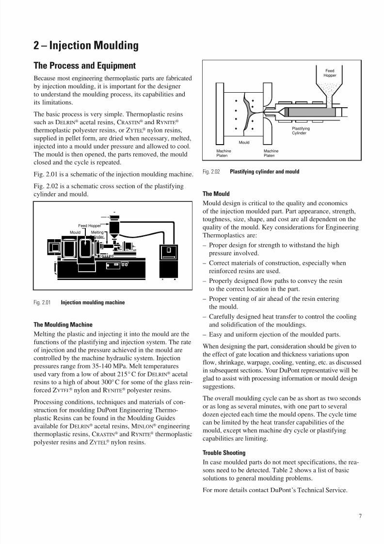
Fig. 2.01 is a schematic of the injection moulding machine.
Fig. 2.02 is a schematic cross section of the plastifying
cylinder and mould.
Fig. 2.01 Injection moulding machine
The Moulding Machine
Melting the plastic and injecting it into the mould are the
functions of the plastifying and injection system. The rateof injection and the pressure achieved in the mould are
controlled by the machine hydraulic system. Injection
pressures range from 35-140 MPa. Melt temperatures
used vary from a low of about 215° C for DELRIN® acetal
resins to a high of about 300°C for some of the glass rein-forced ZYTEL® nylon and RYNITE® polyester resins.
Processing conditions, techniques and materials of con-
struction for moulding DuPont Engineering Thermo-
plastic Resins can be found in the Moulding Guides
available for DELRIN® acetal resins, MINLON® engineeringthermoplastic resins, CRASTIN® and RYNITE® thermoplastic
polyester resins and ZYTEL® nylon resins.
Fig. 2.02 Plastifying cylinder and mould
The Mould
Mould design is critical to the quality and economics
of the injection moulded part. Part appearance, strength,toughness, size, shape, and cost are all dependent on the
quality of the mould. Key considerations for Engineering
Thermoplastics are:
– Proper design for strength to withstand the high
pressure involved.
– Correct materials of construction, especially when
reinforced resins are used.
– Properly designed flow paths to convey the resin
to the correct location in the part.
– Proper venting of air ahead of the resin entering
the mould.
– Carefully designed heat transfer to control the cooling
and solidification of the mouldings.
– Easy and uniform ejection of the moulded parts.
When designing the part, consideration should be given to
the effect of gate location and thickness variations upon
flow, shrinkage, warpage, cooling, venting, etc. as discussedin subsequent sections. Your DuPont representative will be
glad to assist with processing information or mould designsuggestions.
The overall moulding cycle can be as short as two seconds
or as long as several minutes, with one part to several
dozen ejected each time the mould opens. The cycle timecan be limited by the heat transfer capabilities of the
mould, except when machine dry cycle or plastifying
capabilities are limiting.
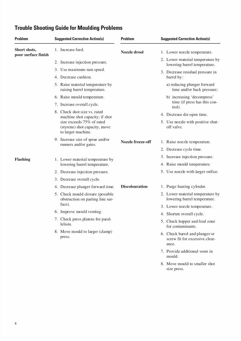
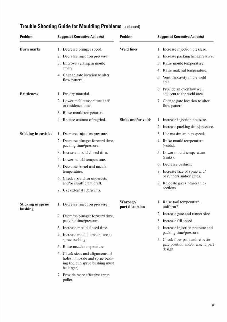
Trouble Shooting
In case moulded parts do not meet specifications, the rea-
sons need to be detected. Table 2 shows a list of basic
solutions to general moulding problems.
For more details contact DuPont’s Technical Service.
7
Feed Hopper
Mould MeltingCylinder
MachinePlaten
MachinePlaten
PlastifyingCylinder
Mould
FeedHopper
7/23/2019 f1236720 DuPont Engineering Polymers General Design Principles Module I
http://slidepdf.com/reader/full/f1236720-dupont-engineering-polymers-general-design-principles-module-i 10/155
Problem Suggested Corrective Action(s)
Short shots, 1. Increase feed.
poor surface finish
2. Increase injection pressure.
3. Use maximum ram speed.
4. Decrease cushion.
5. Raise material temperature by
raising barrel temperature.
6. Raise mould temperature.
7. Increase overall cycle.
8. Check shot size vs. rated
machine shot capacity; if shot
size exceeds 75% of rated
(styrene) shot capacity, moveto larger machine.
9. Increase size of sprue and/orrunners and/or gates.
Flashing 1. Lower material temperature by
lowering barrel temperature.
2. Decrease injection pressure.
3. Decrease overall cycle.
4. Decrease plunger forward time.
5. Check mould closure (possible
obstruction on parting line sur-
face).
6. Improve mould venting.
7. Check press platens for paral-
lelism.
8. Move mould to larger (clamp)
press.
Problem Suggested Corrective Action(s)
Nozzle drool 1. Lower nozzle temperature.
2. Lower material temperature bylowering barrel temperature.
3. Decrease residual pressure in
barrel by:
a) reducing plunger forward
time and/or back pressure;
b) increasing ‘decompress’
time (if press has this con-trol).
4. Decrease die open time.
5. Use nozzle with positive shut-
off valve.
Nozzle freeze-off 1. Raise nozzle temperature.
2. Decrease cycle time.
3. Increase injection pressure.
4. Raise mould temperature.
5. Use nozzle with larger orifice.
Discolouration 1. Purge heating cylinder.
2. Lower material temperature bylowering barrel temperature.
3. Lower nozzle temperature.
4. Shorten overall cycle.
5. Check hopper and feed zone
for contaminants.
6. Check barrel and plunger or
screw fit for excessive clear-ance.
7. Provide additional vents in
mould.
8. Move mould to smaller shotsize press.
8
Trouble Shooting Guide for Moulding Problems
7/23/2019 f1236720 DuPont Engineering Polymers General Design Principles Module I
http://slidepdf.com/reader/full/f1236720-dupont-engineering-polymers-general-design-principles-module-i 11/155
Problem Suggested Corrective Action(s)
Burn marks 1. Decrease plunger speed.
2. Decrease injection pressure.
3. Improve venting in mould
cavity.
4. Change gate location to alter
flow pattern.
Brittleness 1. Pre-dry material.
2. Lower melt temperature and/ or residence time.
3. Raise mould temperature.
4. Reduce amount of regrind.
Sticking in cavities 1. Decrease injection pressure.
2. Decrease plunger forward time,
packing time/pressure.
3. Increase mould closed time.
4. Lower mould temperature.
5. Decrease barrel and nozzle
temperature.
6. Check mould for undercuts
and/or insufficient draft.
7. Use external lubricants.
Sticking in sprue 1. Decrease injection pressure.
bushing
2. Decrease plunger forward time,
packing time/pressure.
3. Increase mould closed time.
4. Increase mould temperature at
sprue bushing.
5. Raise nozzle temperature.
6. Check sizes and alignments of holes in nozzle and sprue bush-
ing (hole in sprue bushing must
be larger).
7. Provide more effective sprue
puller.
Problem Suggested Corrective Action(s)
Weld lines 1. Increase injection pressure.
2. Increase packing time/pressure.
3. Raise mould temperature.
4. Raise material temperature.
5. Vent the cavity in the weldarea.
6. Provide an overflow welladjacent to the weld area.
7. Change gate location to alterflow pattern.
Sinks and/or voids 1. Increase injection pressure.
2. Increase packing time/pressure.
3. Use maximum ram speed.
4. Raise mould temperature
(voids).
5. Lower mould temperature
(sinks).
6. Decrease cushion.
7. Increase size of sprue and/ or runners and/or gates.
8. Relocate gates nearer thicksections.
Warpage/ 1. Raise tool temperature,part distortion uniform?
2. Increase gate and runner size.
3. Increase fill speed.
4. Increase injection pressure and
packing time/pressure.
5. Check flow path and relocate
gate position and/or amend part
design.
9
Trouble Shooting Guide for Moulding Problems (continued)

7/23/2019 f1236720 DuPont Engineering Polymers General Design Principles Module I
http://slidepdf.com/reader/full/f1236720-dupont-engineering-polymers-general-design-principles-module-i 12/155
Problem Suggested Corrective Action(s)
Poor dimensional 1. Set uniform cycle times.control 2. Maintain uniform feed and
cushion from cycle to cycle.
3. Fill mould as rapidly as
possible.
4. Check machine hydraulic and
electrical systems for erratic
performance.
5. Increase gate size.
6. Balance cavities for uniform
flow.
7. Reduce number of cavities.
10
Trouble Shooting Guide for Moulding Problems (continued)
7/23/2019 f1236720 DuPont Engineering Polymers General Design Principles Module I
http://slidepdf.com/reader/full/f1236720-dupont-engineering-polymers-general-design-principles-module-i 13/155
3 – Moulding Considerations
Uniform Walls
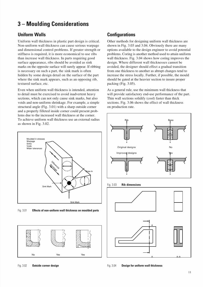
Uniform wall thickness in plastic part design is critical.
Non-uniform wall thickness can cause serious warpage
and dimensional control problems. If greater strength orstiffness is required, it is more economical to use ribsthan increase wall thickness. In parts requiring good
surface appearance, ribs should be avoided as sink
marks on the opposite surface will surely appear. If ribbing
is necessary on such a part, the sink mark is oftenhidden by some design detail on the surface of the part
where the sink mark appears, such as an opposing rib,
textured surface, etc.
Even when uniform wall thickness is intended, attention
to detail must be exercised to avoid inadvertent heavysections, which can not only cause sink marks, but also
voids and non-uniform shrinkage. For example, a simple
structural angle (Fig. 3.01) with a sharp outside corner
and a properly filleted inside corner could present prob-lems due to the increased wall thickness at the corner.
To achieve uniform wall thickness use an external radius
as shown in Fig. 3.02.
Configurations
Other methods for designing uniform wall thickness are
shown in Fig. 3.03 and 3.04. Obviously there are many
options available to the design engineer to avoid potentialproblems. Coring is another method used to attain uniformwall thickness. Fig. 3.04 shows how coring improves the
design. Where different wall thicknesses cannot be
avoided, the designer should effect a gradual transition
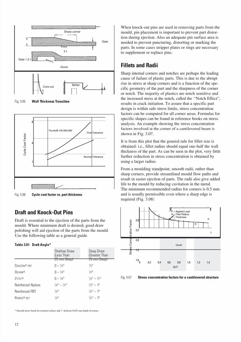
from one thickness to another as abrupt changes tend toincrease the stress locally. Further, if possible, the mould
should be gated at the heavier section to insure proper
packing (Fig. 3.05).
As a general rule, use the minimum wall thickness that
will provide satisfactory end-use performance of the part.Thin wall sections solidify (cool) faster than thick
sections. Fig. 3.06 shows the effect of wall thickness
on production rate.
11
Sink Mark
D i f f e r e n c i a l
S h r i n k a g e
Sink Mark
Draw-In
Moulded in stressesWarpageSinksVoidsWider tolerances
A
A A–ANo Yes Yes
Fig. 3.03 Rib dimensions
Fig. 3.04 Design for uniform wall thickness
Fig. 3.01 Effects of non-uniform wall thickness on moulded parts
Fig. 3.02 Outside corner design
Rib Boss
Original designs No
Improved designs Yes
7/23/2019 f1236720 DuPont Engineering Polymers General Design Principles Module I
http://slidepdf.com/reader/full/f1236720-dupont-engineering-polymers-general-design-principles-module-i 14/155
Fig. 3.05 Wall Thickness Transition
Fig. 3.06 Cycle cost factor vs. part thickness
Draft and Knock-Out Pins
Draft is essential to the ejection of the parts from the
mould. Where minimum draft is desired, good draw
polishing will aid ejection of the parts from the mould.
Use the following table as a general guide.
* Smooth luster finish for textured surface add 1° draft per 0,025 mm depth of texture.
When knock-out pins are used in removing parts from the
mould, pin placement is important to prevent part distor-
tion during ejection. Also an adequate pin surface area is
needed to prevent puncturing, distorting or marking the
parts. In some cases stripper plates or rings are necessary
to supplement or replace pins.
Fillets and Radii
Sharp internal corners and notches are perhaps the leadingcause of failure of plastic parts. This is due to the abrupt
rise in stress at sharp corners and is a function of the spe-
cific geometry of the part and the sharpness of the corner
or notch. The majority of plastics are notch sensitive andthe increased stress at the notch, called the ‘‘Notch Effect’’,
results in crack initiation. To assure that a specific part
design is within safe stress limits, stress concentration
factors can be computed for all corner areas. Formulas for
specific shapes can be found in reference books on stressanalysis. An example showing the stress concentration
factors involved at the corner of a cantilevered beam is
shown in Fig. 3.07.
It is from this plot that the general rule for fillet size is
obtained: i.e., fillet radius should equal one-half the wallthickness of the part. As can be seen in the plot, very little
further reduction in stress concentration is obtained by
using a larger radius.
From a moulding standpoint, smooth radii, rather than
sharp corners, provide streamlined mould flow paths and
result in easier ejection of parts. The radii also give addedlife to the mould by reducing cavitation in the metal.
The minimum recommended radius for corners is 0,5 mm
and is usually permissible even where a sharp edge is
required (Fig. 3.08)
Fig. 3.07 Stress concentration factors for a cantilevered structure
Part Thickness (mm)
C y c l e C o s t F a c t o r
1 6
1
4
8
DELRIN ® 100,500,900Fine Tolerance
Normal Tolerance
R/T
S t r e s s - C o n c e n t r a t i o n F a c t o r
0,2 0,4 0,6 0,8 1,0 1,2 1,40
1,5
2,0
2,5
3,0
1,0
Usual
T
P
P = Applied LoadR = Fillet RadiusT = Thickness
R
Sharp corner
Poor
BetterCore out
Gate 1,5 t
3 t
Gate
Good
12
Table 3.01 Draft Angle*
Shallow Draw Deep Draw(Less Than (Greater Than25 mm Deep) 25 mm Deep)
CRASTIN® PBT 0 – 1 ⁄ 4° 1 ⁄ 2°
DELRIN® 0 – 1 ⁄ 4° 1 ⁄ 2°
ZYTEL® 0 – 1 ⁄ 8° 1 ⁄ 4° – 1 ⁄ 2°
Reinforced Nylons 1 ⁄ 4° – 1 ⁄ 2° 1 ⁄ 2° – 1°
Reinforced PBT 1 ⁄ 2° 1 ⁄ 2° – 1°
RYNITE
®
PET
1
⁄ 2°
1
⁄ 2° – 1°
7/23/2019 f1236720 DuPont Engineering Polymers General Design Principles Module I
http://slidepdf.com/reader/full/f1236720-dupont-engineering-polymers-general-design-principles-module-i 15/155
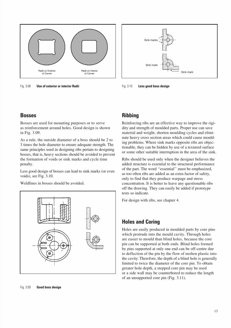
Fig. 3.08 Use of exterior or interior Radii
BossesBosses are used for mounting purposes or to serve
as reinforcement around holes. Good design is shownin Fig. 3.09.
As a rule, the outside diameter of a boss should be 2 to3 times the hole diameter to ensure adequate strength. The
same principles used in designing ribs pertain to designing
bosses, that is, heavy sections should be avoided to prevent
the formation of voids or sink marks and cycle timepenalty.
Less good design of bosses can lead to sink marks (or evenvoids), see Fig. 3.10.
Weldlines in bosses should be avoided.
Fig. 3.09 Good boss design
Fig. 3.10 Less good boss design
RibbingReinforcing ribs are an effective way to improve the rigi-
dity and strength of moulded parts. Proper use can savematerial and weight, shorten moulding cycles and elimi-
nate heavy cross section areas which could cause mould-
ing problems. Where sink marks opposite ribs are objec-
tionable, they can be hidden by use of a textured surfaceor some other suitable interruption in the area of the sink.
Ribs should be used only when the designer believes theadded structure is essential to the structural performance
of the part. The word ‘‘essential’’ must be emphasized,
as too often ribs are added as an extra factor of safety,only to find that they produce warpage and stressconcentration. It is better to leave any questionable ribs
off the drawing. They can easily be added if prototype
tests so indicate.
For design with ribs, see chapter 4.
Holes and Coring
Holes are easily produced in moulded parts by core pinswhich protrude into the mould cavity. Through holesare easier to mould than blind holes, because the core
pin can be supported at both ends. Blind holes formed
by pins supported at only one end can be off-centre due
to deflection of the pin by the flow of molten plastic intothe cavity. Therefore, the depth of a blind hole is generally
limited to twice the diameter of the core pin. To obtain
greater hole depth, a stepped core pin may be used
or a side wall may be counterbored to reduce the lengthof an unsupported core pin (Fig. 3.11).
13
Radii on Exteriorof Corner
Radii on Interiorof Corner
Sink marks
Sink mark
Sink mark

7/23/2019 f1236720 DuPont Engineering Polymers General Design Principles Module I
http://slidepdf.com/reader/full/f1236720-dupont-engineering-polymers-general-design-principles-module-i 16/155
Holes with an axis which runs perpendicular to themould-opening direction require retractable core pins or
split tools. In some designs this can be avoided by placing
holes in walls perpendicular to the parting line, using
steps or extreme taper in the wall (Fig. 3.12). Core pinsshould be polished and draft added to improve ejection.
Where weld lines caused by flow of melt around corepins is objectionable from strength or appearance stand-
point, holes may be spotted or partially cored to facilitate
subsequent drilling as shown in Fig. 3.13.
The guide below, referring to Figure 3.14, will aid in
eliminating part cracking or tear out of the plastic parts.
d = diameter
b ≥ d
c ≥ d
D ≥ d
t = thicknessFor a blind hole, thickness of the bottom should be no
less than 1 ⁄ 6 the hole diameter in order to eliminate
bulging (Fig. 3.15 A). Fig. 3.15 B shows a better design
in which the wall thickness is uniform throughout andthere are no sharp corners where stress concentrations
could develop.
Fig. 3.11 Blind hole with stepped core pin, counterboring
Fig. 3.12 Avoiding side cores by special parting line design
Fig. 3.13 Drilled holes
14
Stepped hole
Counterboring
Hole perpendicular
to parting line
Section A-A
Plastic part
Core
Cavity
Plastic part
Gate
Weld
lines
A B
Drilled
HolesMould section
Plastic part
Moulded
in spot
SpotSpot
UndercutPlastic
partSection A-A
Spot moulded
parallel to
the draw
Spot moulded
perpendicular
to the draw
2/3 D D
A
A
A

7/23/2019 f1236720 DuPont Engineering Polymers General Design Principles Module I
http://slidepdf.com/reader/full/f1236720-dupont-engineering-polymers-general-design-principles-module-i 17/155
Fig. 3.14 Hole design
Fig. 3.15 Blind holes
Threads
When required, external and internal threads can be auto-
matically moulded into the part, eliminating the need for
mechanical thread-forming operations.
External ThreadsParts with external threads can be moulded in two ways.
The least expensive way is to locate the parting line on
the centreline of the thread, Fig. 3.16. It should be consid-ered however that it is generally not possible to avoid an
undercut in the parting line. This should lead to deforma-
tion of the thread on ejection. If this is not acceptable, or
the axis of the thread is in the direction of mould-opening,the alternative is to equip the mould with an external,
thread-unscrewing device.
Fig. 3.16 Moulding external threads without side core
Internal Threads
Internal threads are moulded in parts by using automatic
unscrewing devices or collapsible cores to produce partialthreads. A third method is to use hand-loaded threaded
inserts that are removed from the mould with the part.
Stripped Threads
When threaded parts are to be stripped from the mould,
the thread must be of the roll or round type. The normal
configuration is shown in Fig. 3.17 where R = 0,33 pitch.
Requirements for thread stripping are similar to those forundercuts. Threaded parts with a ratio of diameter to wall
thickness greater than 20 to 1 should be able to be strip-
ped from a mould. Fig. 3.18 and 3.19 show the method of
ejection from the mould.
Fig. 3.17 Stripping of roll-type thread
Fig. 3.18 Mould-ejection of rounded thread-form undercuts – male
Stripperplate orsleeve
Female tool
Pitch
R
Fixed threadedmale core
Depth of thread = R
Clearance between stripperand apex of thread = 1 / 2 R
15
A A D
1/6 D
Min.
A B
Section A-A
d
C
t
d
Hole design
t
D
c
b
Split mould
External
moulded thread
Case 2: Moulded part with external thread;
mould open, part in female cavity
Ejection
Ejector
pinFixed core pin
Moulded part
Female cavity
Source: Injection-Mould Design Fundamentals,
A. B. Glanville and E. N. Denton, Machinery Publishing Co., London 1965
7/23/2019 f1236720 DuPont Engineering Polymers General Design Principles Module I
http://slidepdf.com/reader/full/f1236720-dupont-engineering-polymers-general-design-principles-module-i 18/155
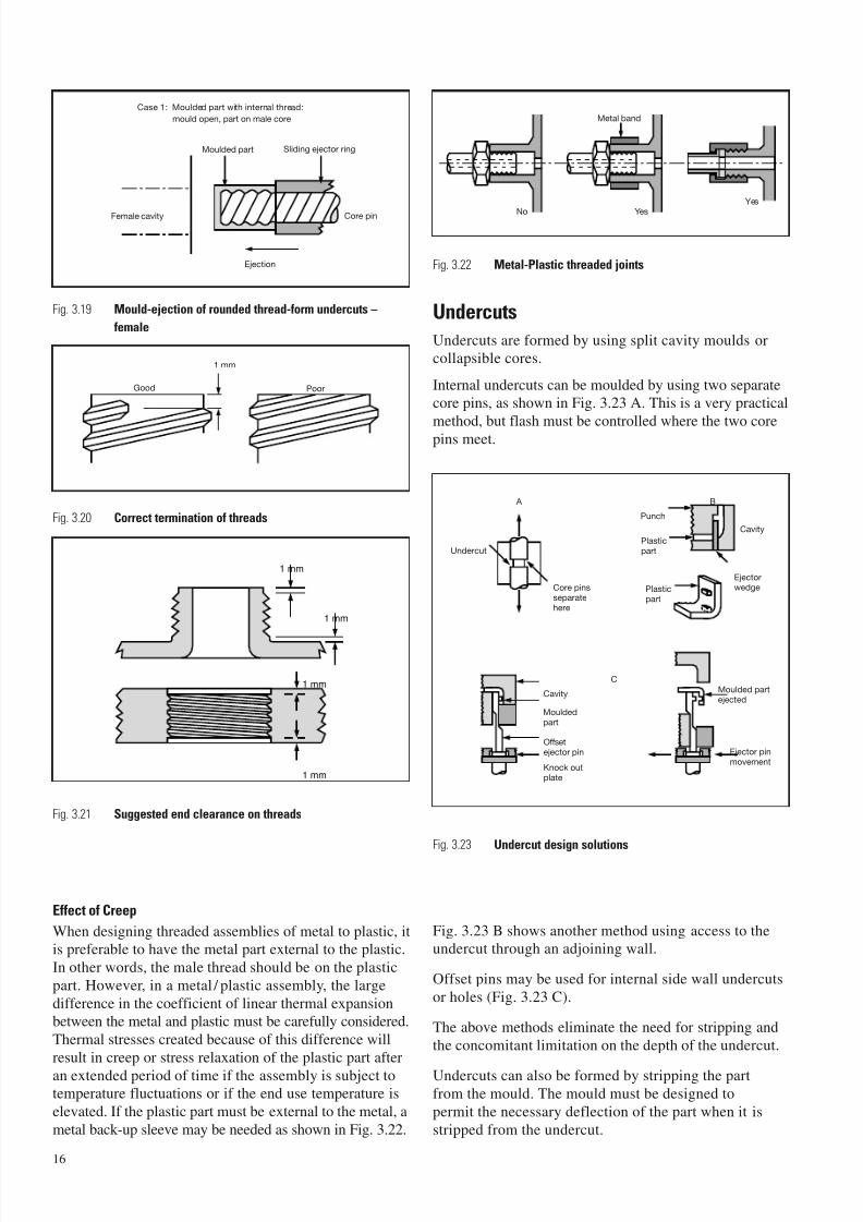
Effect of Creep
When designing threaded assemblies of metal to plastic, itis preferable to have the metal part external to the plastic.
In other words, the male thread should be on the plastic
part. However, in a metal / plastic assembly, the large
difference in the coefficient of linear thermal expansionbetween the metal and plastic must be carefully considered.
Thermal stresses created because of this difference will
result in creep or stress relaxation of the plastic part after
an extended period of time if the assembly is subject totemperature fluctuations or if the end use temperature is
elevated. If the plastic part must be external to the metal, a
metal back-up sleeve may be needed as shown in Fig. 3.22.
Fig. 3.22 Metal-Plastic threaded joints
Undercuts
Undercuts are formed by using split cavity moulds orcollapsible cores.
Internal undercuts can be moulded by using two separatecore pins, as shown in Fig. 3.23 A. This is a very practical
method, but flash must be controlled where the two corepins meet.
Fig. 3.23 Undercut design solutions
Fig. 3.23 B shows another method using access to theundercut through an adjoining wall.
Offset pins may be used for internal side wall undercuts
or holes (Fig. 3.23 C).
The above methods eliminate the need for stripping and
the concomitant limitation on the depth of the undercut.
Undercuts can also be formed by stripping the partfrom the mould. The mould must be designed to
permit the necessary deflection of the part when it is
stripped from the undercut.
16
Case 1: Moulded part with internal thread:
mould open, part on male core
Female cavity
Ejection
Moulded part Sliding ejector ring
Core pin
Good
1 mm
Poor
1 mm
1 mm
1 mm
1 mm
No Yes
Metal band
Yes
A B
Undercut
Core pinsseparatehere
Plasticpart
Plasticpart
Punch
Cavity
Ejectorwedge
Cavity
Mouldedpart
Offsetejector pin
Knock outplate
C
Moulded partejected
Ejector pinmovement
Fig. 3.19 Mould-ejection of rounded thread-form undercuts –
female
Fig. 3.20 Correct termination of threads
Fig. 3.21 Suggested end clearance on threads
7/23/2019 f1236720 DuPont Engineering Polymers General Design Principles Module I
http://slidepdf.com/reader/full/f1236720-dupont-engineering-polymers-general-design-principles-module-i 19/155
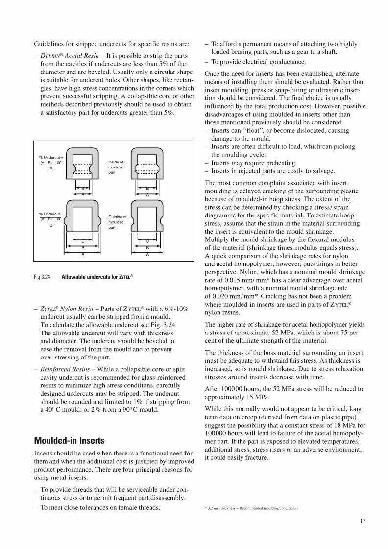
Guidelines for stripped undercuts for specific resins are:
– D ELRIN ® Acetal Resin – It is possible to strip the partsfrom the cavities if undercuts are less than 5% of the
diameter and are beveled. Usually only a circular shape
is suitable for undercut holes. Other shapes, like rectan-
gles, have high stress concentrations in the corners which
prevent successful stripping. A collapsible core or othermethods described previously should be used to obtain
a satisfactory part for undercuts greater than 5%.
Fig 3.24 Allowable undercuts for ZYTEL®
– Z YTEL® Nylon Resin – Parts of ZYTEL® with a 6%-10%undercut usually can be stripped from a mould.
To calculate the allowable undercut see Fig. 3.24.
The allowable undercut will vary with thickness
and diameter. The undercut should be beveled toease the removal from the mould and to prevent
over-stressing of the part.
– Reinforced Resins – While a collapsible core or split
cavity undercut is recommended for glass-reinforced
resins to minimize high stress conditions, carefullydesigned undercuts may be stripped. The undercutshould be rounded and limited to 1% if stripping from
a 40° C mould; or 2% from a 90°C mould.
Moulded-in Inserts
Inserts should be used when there is a functional need for
them and when the additional cost is justified by improved
product performance. There are four principal reasons for
using metal inserts:– To provide threads that will be serviceable under con-
tinuous stress or to permit frequent part disassembly.
– To meet close tolerances on female threads.
– To afford a permanent means of attaching two highlyloaded bearing parts, such as a gear to a shaft.
– To provide electrical conductance.
Once the need for inserts has been established, alternatemeans of installing them should be evaluated. Rather than
insert moulding, press or snap-fitting or ultrasonic inser-
tion should be considered. The final choice is usuallyinfluenced by the total production cost. However, possibledisadvantages of using moulded-in inserts other than
those mentioned previously should be considered:
– Inserts can ‘‘float’’, or become dislocated, causing
damage to the mould.
– Inserts are often difficult to load, which can prolong
the moulding cycle.
– Inserts may require preheating.
– Inserts in rejected parts are costly to salvage.
The most common complaint associated with insert
moulding is delayed cracking of the surrounding plasticbecause of moulded-in hoop stress. The extent of the
stress can be determined by checking a stress/ strain
diagramme for the specific material. To estimate hoop
stress, assume that the strain in the material surroundingthe insert is equivalent to the mould shrinkage.
Multiply the mould shrinkage by the flexural modulus
of the material (shrinkage times modulus equals stress).
A quick comparison of the shrinkage rates for nylonand acetal homopolymer, however, puts things in better
perspective. Nylon, which has a nominal mould shrinkage
rate of 0,015 mm/ mm* has a clear advantage over acetal
homopolymer, with a nominal mould shrinkage rateof 0,020 mm/ mm*. Cracking has not been a problem
where moulded-in inserts are used in parts of ZYTEL®
nylon resins.
The higher rate of shrinkage for acetal homopolymer yields
a stress of approximate 52 MPa, which is about 75 per
cent of the ultimate strength of the material.
The thickness of the boss material surrounding an insert
must be adequate to withstand this stress. As thickness isincreased, so is mould shrinkage. Due to stress relaxation
stresses around inserts decrease with time.
After 100000 hours, the 52 MPa stress will be reduced to
approximately 15 MPa.
While this normally would not appear to be critical, long
term data on creep (derived from data on plastic pipe)
suggest the possibility that a constant stress of 18 MPa for
100000 hours will lead to failure of the acetal homopoly-mer part. If the part is exposed to elevated temperatures,
additional stress, stress risers or an adverse environment,
it could easily fracture.
* 3,2 mm thickness – Recommended moulding conditions.
17
B
A
B
A
C
B
A
C
B
A
% Undercut =
(A – B) · 100
B
% Undercut =
(A – B) · 100
C
Outside of
moulded
part
Inside of
moulded
part
7/23/2019 f1236720 DuPont Engineering Polymers General Design Principles Module I
http://slidepdf.com/reader/full/f1236720-dupont-engineering-polymers-general-design-principles-module-i 20/155
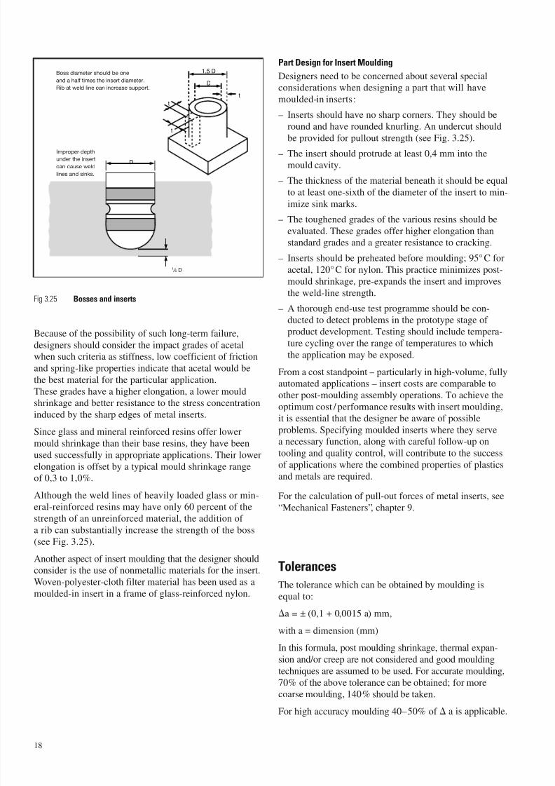
Fig 3.25 Bosses and inserts
Because of the possibility of such long-term failure,
designers should consider the impact grades of acetalwhen such criteria as stiffness, low coefficient of friction
and spring-like properties indicate that acetal would be
the best material for the particular application.
These grades have a higher elongation, a lower mouldshrinkage and better resistance to the stress concentration
induced by the sharp edges of metal inserts.
Since glass and mineral reinforced resins offer lower
mould shrinkage than their base resins, they have been
used successfully in appropriate applications. Their lower
elongation is offset by a typical mould shrinkage rangeof 0,3 to 1,0%.
Although the weld lines of heavily loaded glass or min-eral-reinforced resins may have only 60 percent of the
strength of an unreinforced material, the addition of
a rib can substantially increase the strength of the boss
(see Fig. 3.25).
Another aspect of insert moulding that the designer shouldconsider is the use of nonmetallic materials for the insert.
Woven-polyester-cloth filter material has been used as a
moulded-in insert in a frame of glass-reinforced nylon.
Part Design for Insert Moulding
Designers need to be concerned about several specialconsiderations when designing a part that will have
moulded-in inserts:
– Inserts should have no sharp corners. They should be
round and have rounded knurling. An undercut should
be provided for pullout strength (see Fig. 3.25).
– The insert should protrude at least 0,4 mm into themould cavity.
– The thickness of the material beneath it should be equal
to at least one-sixth of the diameter of the insert to min-
imize sink marks.
– The toughened grades of the various resins should be
evaluated. These grades offer higher elongation thanstandard grades and a greater resistance to cracking.
– Inserts should be preheated before moulding; 95°C for
acetal, 120°C for nylon. This practice minimizes post-
mould shrinkage, pre-expands the insert and improves
the weld-line strength.
– A thorough end-use test programme should be con-ducted to detect problems in the prototype stage of
product development. Testing should include tempera-
ture cycling over the range of temperatures to which
the application may be exposed.
From a cost standpoint – particularly in high-volume, fully
automated applications – insert costs are comparable toother post-moulding assembly operations. To achieve the
optimum cost / performance results with insert moulding,
it is essential that the designer be aware of possible
problems. Specifying moulded inserts where they servea necessary function, along with careful follow-up on
tooling and quality control, will contribute to the success
of applications where the combined properties of plastics
and metals are required.
For the calculation of pull-out forces of metal inserts, see
“Mechanical Fasteners”, chapter 9.
Tolerances
The tolerance which can be obtained by moulding is
equal to:
a = ± (0,1 + 0,0015 a) mm,
with a = dimension (mm)
In this formula, post moulding shrinkage, thermal expan-
sion and/or creep are not considered and good moulding
techniques are assumed to be used. For accurate moulding,
70% of the above tolerance can be obtained; for morecoarse moulding, 140% should be taken.
For high accuracy moulding 40–50% of a is applicable.
18
D
1,5 D
D
t
t
t
Boss diameter should be one
and a half times the insert diameter.
Rib at weld line can increase support.
Improper depth
under the insert
can cause weld
lines and sinks.
1 ⁄ 6 D
7/23/2019 f1236720 DuPont Engineering Polymers General Design Principles Module I
http://slidepdf.com/reader/full/f1236720-dupont-engineering-polymers-general-design-principles-module-i 21/155
Shrinkage and Warpage
When plastic material is injected into a cavity, it starts to
cool down, whereby its volume decreases. A measure for
this volume decrease is given by the difference betweenmelt density and solid density. As cooling rates in the
cavity are very high and non-uniform, the frozen material
will also incorporate internal stresses. These stresses mayrelieve after ejection from the cavity, which process can beaccelerated by keeping the part at elevated temperatures.
Shrinkage can be defined by the following formula:
S = (D - d) / D (× 100%).
D = dimension of mould cavity.
d = dimension of moulded part.
Shrinkage is usually not isotropic; it is direction depen-
dant, in particular for glass-fibre reinforced materials.To be distinguished are:
– shrinkage in flow direction;
– shrinkage normal to flow;
– shrinkage in thickness direction.
The sum of these three shrinkages must be equal to the
volumetric shrinkage of a material, which can be obtainedfrom the difference between melt density and solid den-
sity, or from pVT-diagrams.
Besides on material, shrinkage is further dependant on
processing conditions, (such as injection-speed, hold-pressure, hold-pressure time, runner/gate-dimensions and
mould temperature), on part shape, (during injection the
flow-direction may change) and part thickness, (thicker
parts have usually a thicker central layer with less orienta-tion).
The shrinkage contribution caused by stress relieve afterejection from the mould is called Post Mould Shrinkage.
Warpage is caused by internal stresses, which on their turnare the result of anisotropic shrinkage properties and non-
uniform shrinkages.
Anisotropic shrinkage properties are mainly defined bythe presence of reinforcements with high aspect ratios,
(short glass fibres: ratio = 20), but also by different elastic
behaviour of stretched cristals during filling, (residual
stresses).
Non-uniform shrinkages can be the result of :
– anisotropic shrinkage;
– non-uniform thickness;
– non-uniform orientation;
– non-uniform mould temperatures;
– non-uniform hold-pressure (time).
Computer simulations have been developed to predict
shrinkage and warpage. The reliability of the results of these predictions is increasing, particularly for parts made
out of glass-fibre reinforced materials, as to day also meth-
ods are available to include shrinkage over the thickness,
in which DuPont plays an important role.
Still one should be aware that it is very difficult to guar-
antee good results in all cases, as for instance the anisotropic
shrinkage properties of a glass fibre reinforced materialeasily can be influenced by the screw and nozzle of an
injection moulding machine, as well as by narrow gates.
At these locations significant breakage of fibres may
occur, thus affecting the anisotropic properties.
19

7/23/2019 f1236720 DuPont Engineering Polymers General Design Principles Module I
http://slidepdf.com/reader/full/f1236720-dupont-engineering-polymers-general-design-principles-module-i 22/155
20
7/23/2019 f1236720 DuPont Engineering Polymers General Design Principles Module I
http://slidepdf.com/reader/full/f1236720-dupont-engineering-polymers-general-design-principles-module-i 23/155
4 – Structural Design Formulae
Short Term Loads
If a plastic part is subjected to a load for only a short time
(10-20 minutes) and the part is not stressed beyond its
elastic limit, then classical design formulae found in engi-
neering texts as reprinted here can be used with sufficient
accuracy. These formulae are based on Hooke’s Law
which states that in the elastic region the part will recover
to its original shape after stressing, and that stress is pro-
portional to strain.
Tensile Stress – Short Term
Hooke’s law is expressed as:
=
Ewhere:
= strain (%/100) =
= stress (MPa), defined as =
= modulus of elasticity (MPa)
F = total force (N)
A = total area (mm2)
l = length of member (mm)
l = elongation (mm)
Bending Stress
In bending, the maximum stress is calculated from:
b =My
=M
I Z
where:
b = bending stress (MPa)
M = bending moment (Nmm)
I = moment of inertia (mm4)
y = distance from neutral axis to extreme outerfibre (mm)
Z = = section modulus (mm3)
The I and y values for some typical cross-sections are
shown in Table 4.01.
Beams
Various beam loading conditions are shown in Table 4.02.
Beams in Torsion
When a plastic part is subjected to a twisting moment, itis considered to have failed when the shear strength of the
part is exceeded.
The basic formula for torsional stress is: =MTr
K
where:
= Shear stress (MPa)
MT = Twisting Moment (N · mm)
r = Distance to centre of rotation (mm)
K = Torsional Constant (mm4)
Formulae for sections in torsion are given in Table 4.03.
To determine , angle of twist of the part whose lengthis l , the equation shown below is used:
=MTl
KG
where:
= angle of twist (radians)
K = Torsional Constant (mm4)
l = length of member (mm)
G = modulus in shear (MPa)
To approximate G, the shear modulus, use the equation,
G =E
(for isotropic materials)2 (1+)
where:E = Modulus (MPa)
= Poisson’s Ratio; generally for plastics:
E < 500: = 0,45
500 < E < 2500: = 0,40
E > 2500: = 0,35
Tubing and Pressure Vessels
Internal pressure in a tube, pipe or pressure vessel creates
three types of stresses in the part: Hoop, meridional andradial. See Table 4.04.
Buckling of Columns, Rings and Arches
The stress level of a short column in compression is
calculated from the equation,
c =FA
The mode of failure in short columns is compressive
failure by crushing. As the length of the column
increases, however, this simple equation becomesinvalid as the column approaches a buckling mode
of failure. To determine if buckling will be a factor,
consider a thin column of length l , having frictionlessrounded ends and loaded by force F. As F increases, thecolumn will shorten in accordance with Hooke’s Law.
F can be increased until a critical value of FC is reached.
21
Iy
l
l F
A
7/23/2019 f1236720 DuPont Engineering Polymers General Design Principles Module I
http://slidepdf.com/reader/full/f1236720-dupont-engineering-polymers-general-design-principles-module-i 24/155
Any load above FC will cause the column to buckle.
In equation form:
FC =2 Et I
l 2
In this formula, which is called the Euler Formula for
round ended columns:
Et = Tangent modulus at stress C
I = moment of inertia of cross section.
A safety factor of 3 to 4 should be applied.
Thus, if the value for FC is less than the allowable
load under pure compression, the buckling formula
should be used.
If the end conditions are altered from the round ends, as
is the case with most plastic parts, then the critical loadis also altered. See Table 4.05 for additional end effect
conditions for columns.
Flat Plates
Flat plates are another standard shape found in plastic partdesign. Their analysis can be useful in the design of such
products as pump housings and valves.
A few of the most commonly used geometrics are shown
in Table 4.06.
Arbitrary Structures
A lot of injection moulded parts have a shape which
cannot be compared with one of the structures from
Tables 4.01 to 4.06.
Deformations of, and stresses in these parts, can be
analysed by using the Finite Element method.
For recommended material properties, mesh to be used,
simulation of loads and boundary conditions, and assess-
ment of results, DuPont’s Engineering Polymers Techni-cal Service can provide assistance.
Equivalent Stress / Allowable Stress
Tensile and bending stresses are always pependicular
(normal) to a considered cross section, while shear stressesact in the cross-sectional plane. At a given location there
are often multiple stress components acting at the same
time. To express the “danger” of such a multiaxial stress
state by only one number, “equivalent stresses” are used.A widely known formula to calculate the equivalent
stress in isotropic materials is the “Von Mises” criterium
(two-dimensional):
eq, VonMises = x2 + y
2 – x y + 3xy
with: x, y: normal stress
xy: shear stress
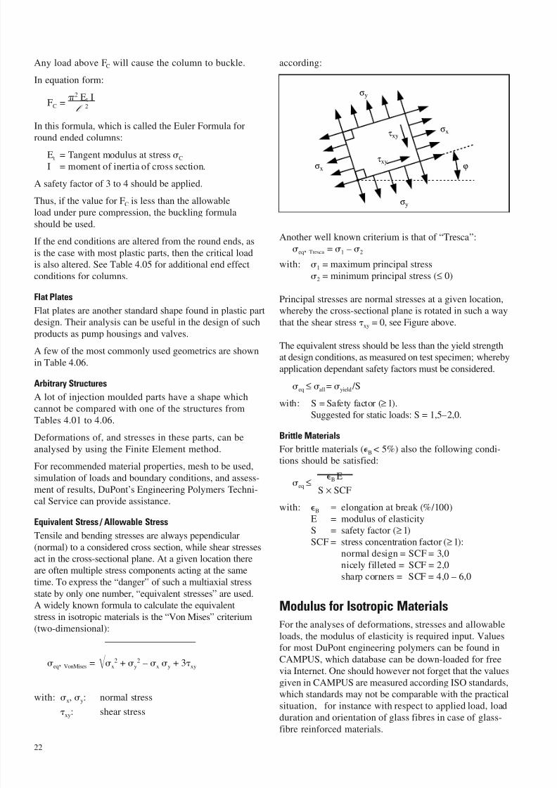
according:
Another well known criterium is that of “Tresca”:
eq, Tresca = 1 – 2
with: 1 = maximum principal stress
2 = minimum principal stress (≤ 0)
Principal stresses are normal stresses at a given location,whereby the cross-sectional plane is rotated in such a way
that the shear stress xy = 0, see Figure above.
The equivalent stress should be less than the yield strengthat design conditions, as measured on test specimen; whereby
application dependant safety factors must be considered.
eq ≤ all= yield /S
with: S = Safety factor (≥ 1).
Suggested for static loads: S = 1,5–2,0.
Brittle Materials
For brittle materials (B < 5%) also the following condi-tions should be satisfied:
eq ≤B E
S × SCF
with: B = elongation at break (%/100)E = modulus of elasticityS = safety factor (≥ 1)SCF = stress concentration factor (≥ 1):
normal design = SCF = 3,0nicely filleted = SCF = 2,0sharp corners = SCF = 4,0 – 6,0
Modulus for Isotropic Materials
For the analyses of deformations, stresses and allowable
loads, the modulus of elasticity is required input. Valuesfor most DuPont engineering polymers can be found in
CAMPUS, which database can be down-loaded for free
via Internet. One should however not forget that the values
given in CAMPUS are measured according ISO standards,
which standards may not be comparable with the practicalsituation, for instance with respect to applied load, load
duration and orientation of glass fibres in case of glass-
fibre reinforced materials.
22
τxy
τxy
σy
σx
σx
ϕ
σy
7/23/2019 f1236720 DuPont Engineering Polymers General Design Principles Module I
http://slidepdf.com/reader/full/f1236720-dupont-engineering-polymers-general-design-principles-module-i 25/155
The following guidelines should lead to more preciseresults when analyses are carried out with isotropic
material properties:
– Static analysis,
use stress-strain curve at design temperature,
– non reinforced materials:
use appearant modulus at 1% strain.– reinforced materials:
define appearant modulus at 0,5% strain,
use 90% of appearant modulus for highly oriented
fibres;
use 80% of appearant modulus for good orientedfibres;
use 50% of appearant modulus for poorly oriented
fibres.
The appearant modulus is defined by the slope of the
line, connecting the origin off the stress-strain curve
with a point at a given strain:Eapp = σ0 / ε0, see also Fig 4.01.
For polyamides the stress-strain curves at 50 RH
(conditioned) should be selected.
Corrections for creep are applicable for load durations
longer than 0,5 hour, see also paragraph “Long Term
Loads”. Then, instead of the standard stress-strain curve,an isochronous stress strain-curve at the design tem-
perature and for the applicable time should be used.
– Dynamic analysis,
use Dynamic Mechanical Analyser measurements,
– non reinforced materials:
use value at design temperature.
– reinforced materials:
use 85 % of value at design temperature.
Orthotropic Materials
Glass fibre reinforced plastics have properties (modulus of
elasticity, coefficient of linear thermal expansion, tensile
strength), which are significantly different for in-flow and
transverse to flow directions. Analyses with orthotropic(anisotropic) materials is in general only possible with the
finite element method. In this approach, a flow analysis is
included to calculate the material orientations of the ele-ments. Formulae to calculate the equivalent stresses in
othotropic materials exist, but are complicated. A more
simple (but still good enough) approach is to adjust the
allowable stress (tensile / S), to a value applicable for thegiven orientation.
Other Loads
Fatigue Resistance
When materials are stressed cyclically they tend to fail
at levels of stress below their ultimate tensile strength.
The phenomenon is termed ‘‘fatigue failure’’.
Fatigue resistance data (in air) for injection mouldedmaterial samples are shown in the product modules.
These data were obtained by stressing the samples at aconstant level at 1800 cpm and observing the number of
cycles to failure at each testing load on a Sonntag-Univer-
sal testing machine.
Experiment has shown that the frequency of loading
has no effect on the number of cycles to failure at a given
level of stress, below frequencies of 1800 cpm.However, it is probable that at higher frequencies internal
generation of heat within the specimen may cause more
rapid failure.
Impact Resistance
End-use applications of materials can be divided into two
categories.
– Applications where the part must withstand impact
loadings on only a few occasions during its life.
– Applications where the part must withstand repeated
impact loadings throughout its life.
Materials considered to have good impact strength vary
widely in their ability to withstand repeated impact.Where an application subject to repeated impact is
involved, the designer should seek specific data before
making a material selection. Such data can be found in the
product modules for DELRIN® resin and ZYTEL® resin,both of which demonstrate excellent resistance to repeated
impact.
The energy of an impact must either be absorbed or trans-
mitted by a part, otherwise mechanical failure will occur.
Two approaches can be used to increase the impact resis-
tance of a part by design:
– Increase the area of load application to reduce stresslevel.
– Dissipate shock energy by designing the part to deflect
under load.
Designing flexibility into the part significantly increases
the volume over which impact energy is absorbed.
Thus the internal forces required to resist the impact are
greatly reduced.
23
7/23/2019 f1236720 DuPont Engineering Polymers General Design Principles Module I
http://slidepdf.com/reader/full/f1236720-dupont-engineering-polymers-general-design-principles-module-i 26/155
It should be emphasized that structural design for impact
loading is usually a very complex and often empirical
exercice. Since there are specific formulations of
engineering materials available for impact applications,
the designer should work around the properties of
these materials during the initial drawing stage, and
make a final selection via parts from a prototype tool
which have been rigorously tested under actual end-use
conditions.
Thermal Expansion and Stress
The effects of thermal expansion should not be overlooked
in designing with thermoplastics.
For unreinforced plastic materials, the thermal expansion
coefficient may be six to eight times higher than the coef-
ficient of most metals. This differential must be taken into
account when the plastic part is to function in conjunction
with a metal part. It need not be a problem if proper
allowances are made for clearances, fits, etc.
For example, if a uniform straight bar is subjected to a
temperature change T, and the ends are not constrained,
the change in length can be calculated from:
L = T × × L
where:
L = change in length (mm)
T = change in temperature (°C)
= thermal expansion coefficient (mm/mm°C)
L = original length (mm)
If the ends are constrained, the stress developed is:
= T × × E
where:
= compressive stress (MPa)
E = modulus (MPa)
The thermal stresses in a plate, constrained in two direc-tions are:
= T × × E / (1 – )
where: = Poissons ratio
When a plastic part is constrained by metal, the effect of stress relaxation as the temperature varies must be consid-
ered, since the stiffer metal part will prevent the plastic
part from expanding or contracting, as the case may be.
Long Term Loads
Plastic materials under load will undergo an initial
deformation the instant the load is applied and willcontinue to deform at a slower rate with continued
application of the load. This additional deformationwith time is called ‘‘creep’’.
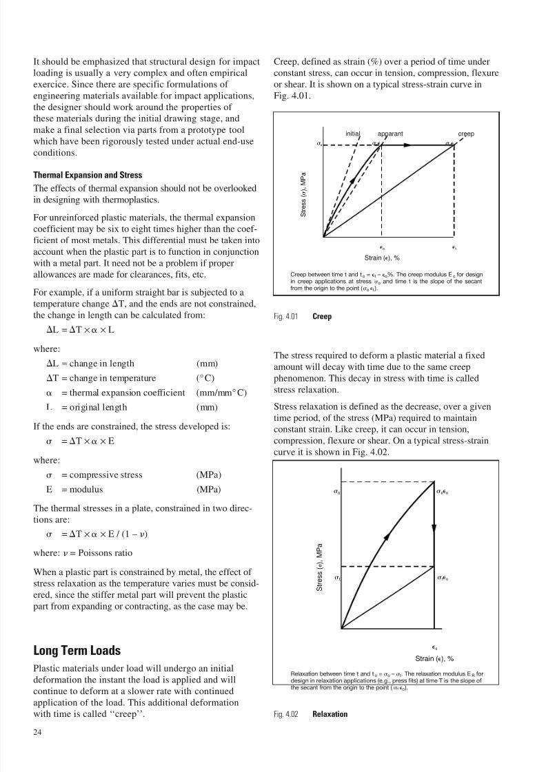
Creep, defined as strain (%) over a period of time underconstant stress, can occur in tension, compression, flexure
or shear. It is shown on a typical stress-strain curve in
Fig. 4.01.
Fig. 4.01 Creep
The stress required to deform a plastic material a fixed
amount will decay with time due to the same creep
phenomenon. This decay in stress with time is called
stress relaxation.
Stress relaxation is defined as the decrease, over a giventime period, of the stress (MPa) required to maintainconstant strain. Like creep, it can occur in tension,
compression, flexure or shear. On a typical stress-strain
curve it is shown in Fig. 4.02.
Fig. 4.02 Relaxation
24
o t
o oo o t
Strain (), %
S t r e s s ( ) , M P a
initial apparant creep
Creep between time t and to = t – o%. The creep modulus Ec for designin creep applications at stress o and time t is the slope of the secantfrom the origin to the point ( o t ).
o
o
t
oo
to
Strain (), %
S t r e s s ( σ ) , M P a
Relaxation between time t and to =
o –
t. The relaxation modulus ER fordesign in relaxation applications (e.g., press fits) at time T is the slope ofthe secant from the origin to the point ( t o ).
7/23/2019 f1236720 DuPont Engineering Polymers General Design Principles Module I
http://slidepdf.com/reader/full/f1236720-dupont-engineering-polymers-general-design-principles-module-i 27/155
Laboratory experiments with injection moulded specimenshave shown that for stresses below about 1 ⁄ 3 of the ultimate
tensile strength of the material at any temperature, the
secant moduli in creep and relaxation at any time of load-ing may be considered similar for engineering purposes.
Furthermore, under these conditions, the secant moduli in
creep and relaxation in tension, compression and flexure
are approximately equal.
A typical problem using creep data found in the properties
sections is shown below:
Cylinder under Pressure
Example 1 : A Pressure Vessel Under Long Term Loading
As previously noted, it is essential for the designer
to itemise the end-use requirements and environment
of a part before attempting to determine its geometry.
This is particularly true of a pressure vessel, where
safety is such a critical factor. In this example, we willdetermine the side wall thickness of a gas container
which must meet these requirements:
a) retain pressure of 0,7 MPa;
b) for 10 years;
c) at 65° C.
The inside radius of the cylinder is 9 mm and the length
is 50 mm. Because the part will be under pressure fora long period of time, one cannot safely use short-term
stress-strain data but should refer to creep data or,
preferably, longterm burst data from actual pressure
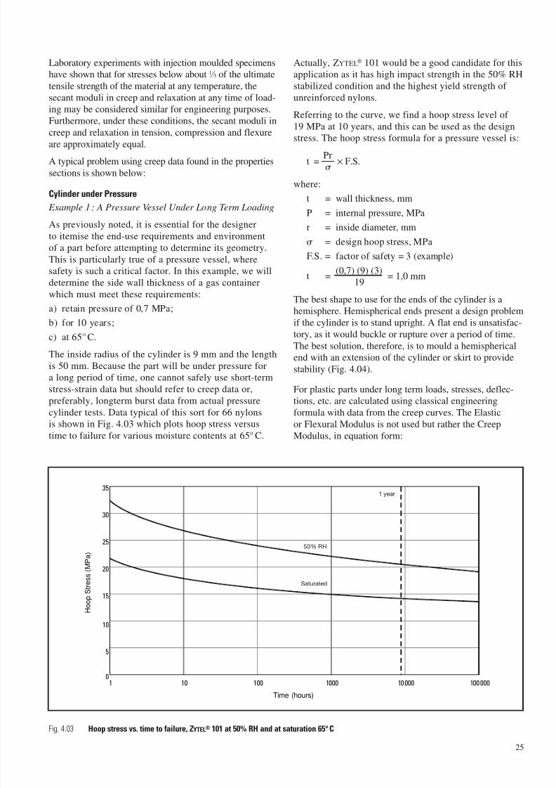
cylinder tests. Data typical of this sort for 66 nylonsis shown in Fig. 4.03 which plots hoop stress versus
time to failure for various moisture contents at 65° C.
Actually, ZYTEL® 101 would be a good candidate for thisapplication as it has high impact strength in the 50% RH
stabilized condition and the highest yield strength of
unreinforced nylons.
Referring to the curve, we find a hoop stress level of
19 MPa at 10 years, and this can be used as the design
stress. The hoop stress formula for a pressure vessel is:
t =Pr
× F.S.
where:
t = wall thickness, mm
P = internal pressure, MPa
r = inside diameter, mm
= design hoop stress, MPa
F.S. = factor of safety = 3 (example)
t =(0,7) (9) (3)
= 1,0 mm19
The best shape to use for the ends of the cylinder is ahemisphere. Hemispherical ends present a design problem
if the cylinder is to stand upright. A flat end is unsatisfac-
tory, as it would buckle or rupture over a period of time.
The best solution, therefore, is to mould a hemisphericalend with an extension of the cylinder or skirt to provide
stability (Fig. 4.04).
For plastic parts under long term loads, stresses, deflec-tions, etc. are calculated using classical engineering
formula with data from the creep curves. The Elasticor Flexural Modulus is not used but rather the Creep
Modulus, in equation form:
25
Fig. 4.03 Hoop stress vs. time to failure, ZYTEL® 101 at 50% RH and at saturation 65°C
10010 1000 10 000 100 0001
5
0
15
10
20
25
30
35
Time (hours)
H o o p S t r e s s ( M P a )
1 year
50% RH
Saturated
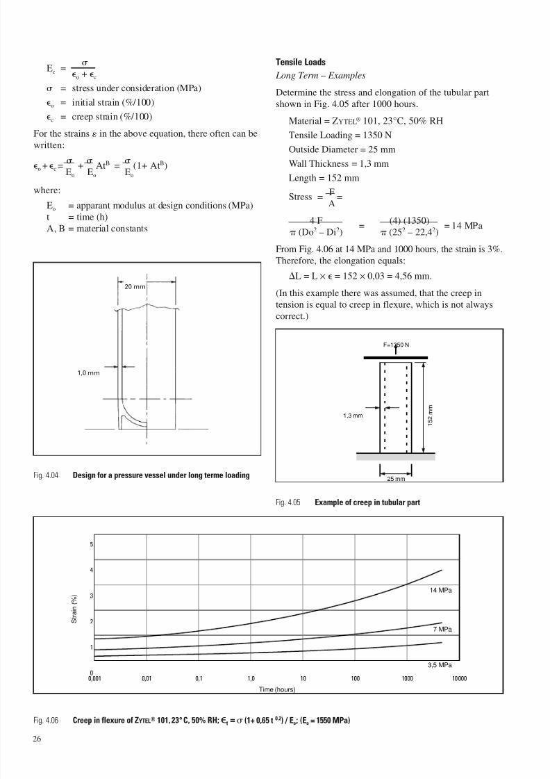
7/23/2019 f1236720 DuPont Engineering Polymers General Design Principles Module I
http://slidepdf.com/reader/full/f1236720-dupont-engineering-polymers-general-design-principles-module-i 28/155
Ec =
o + c
= stress under consideration (MPa)
o = initial strain (%/100)
c = creep strain (%/100)
For the strains in the above equation, there often can bewritten:
o + c =
+
AtB =
(1+ AtB)Eo Eo Eo
where:
Eo = apparant modulus at design conditions (MPa)
t = time (h)
A, B = material constants
Tensile Loads
Long Term – Examples
Determine the stress and elongation of the tubular part
shown in Fig. 4.05 after 1000 hours.
Material = ZYTEL® 101, 23°C, 50% RH
Tensile Loading = 1350 NOutside Diameter = 25 mm
Wall Thickness = 1,3 mm
Length = 152 mm
Stress =F
=A
4 F=
(4) (1350)= 14 MPa
(Do2 – Di2) (252 – 22,42)
From Fig. 4.06 at 14 MPa and 1000 hours, the strain is 3%.
Therefore, the elongation equals:
L = L × = 152 × 0,03 = 4,56 mm.
(In this example there was assumed, that the creep in
tension is equal to creep in flexure, which is not always
correct.)
26
Fig. 4.06 Creep in flexure of ZYTEL® 101, 23°C, 50% RH; t = (1+ 0,65 t 0.2) / Eo; (Eo = 1550 MPa)
25 mm
F=1350 N
1,3 mm
1 5 2 m m
0,10,01 101,0 1000 100001000,001
2
3
4
5
0
1
14 MPa
7 MPa
3,5 MPa
Time (hours)
S t r a i n ( % )
20 mm
1,0 mm
Fig. 4.04 Design for a pressure vessel under long terme loading
Fig. 4.05 Example of creep in tubular part
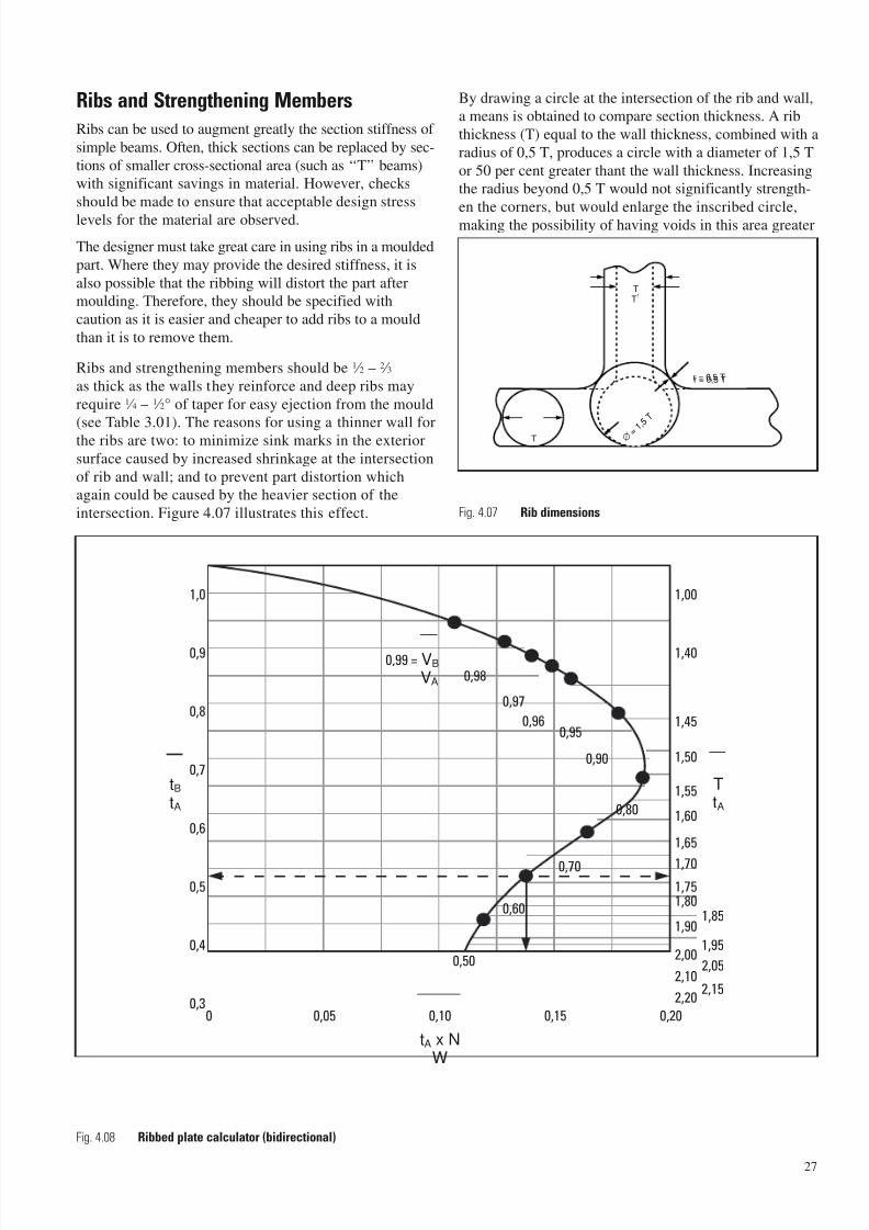
7/23/2019 f1236720 DuPont Engineering Polymers General Design Principles Module I
http://slidepdf.com/reader/full/f1236720-dupont-engineering-polymers-general-design-principles-module-i 29/155
Ribs and Strengthening Members
Ribs can be used to augment greatly the section stiffness of
simple beams. Often, thick sections can be replaced by sec-
tions of smaller cross-sectional area (such as ‘‘T’’ beams)with significant savings in material. However, checks
should be made to ensure that acceptable design stress
levels for the material are observed.
The designer must take great care in using ribs in a moulded
part. Where they may provide the desired stiffness, it is
also possible that the ribbing will distort the part aftermoulding. Therefore, they should be specified with
caution as it is easier and cheaper to add ribs to a mould
than it is to remove them.
Ribs and strengthening members should be 1 ⁄ 2 – 2 ⁄ 3
as thick as the walls they reinforce and deep ribs may
require 1 ⁄ 4 – 1 ⁄ 2° of taper for easy ejection from the mould(see Table 3.01). The reasons for using a thinner wall for
the ribs are two: to minimize sink marks in the exterior
surface caused by increased shrinkage at the intersection
of rib and wall; and to prevent part distortion whichagain could be caused by the heavier section of the
intersection. Figure 4.07 illustrates this effect.
By drawing a circle at the intersection of the rib and wall,a means is obtained to compare section thickness. A rib
thickness (T) equal to the wall thickness, combined with a
radius of 0,5 T, produces a circle with a diameter of 1,5 T
or 50 per cent greater thant the wall thickness. Increasingthe radius beyond 0,5 T would not significantly strength-
en the corners, but would enlarge the inscribed circle,
making the possibility of having voids in this area greater
27
Fig. 4.08 Ribbed plate calculator (bidirectional)
tA x NW
0,050 0,15 0,200,100,3
0,4
0,5
0,6
0,7
0,8
0,9
1,0
tBtA
TtA
2,20 2,15
2,102,05
2,00 1,95
1,90
1,00
1,40
1,45
0,99 = VB
VA
1,50
1,55
1,60
1,65
1,70
1,751,80
1,85
0,98
0,97
0,960,95
0,90
0,80
0,70
0,60
0,50
r = 0,5 T
T
TT
1
∅ = 1 , 5 T
r = 0,5 T
Fig. 4.07 Rib dimensions

7/23/2019 f1236720 DuPont Engineering Polymers General Design Principles Module I
http://slidepdf.com/reader/full/f1236720-dupont-engineering-polymers-general-design-principles-module-i 30/155
28
than if the radius remained 0,5 T. However if the rib ismade thinner than the wall (dotted lines in Fig. 4.07) the
radius in the corners can be in proper proportion to the
new rib thickness, T1, to prevent high stress concentrationand voids at the juncture, without enlarging the diameter
of the enclosed circle.
Since ribbing is in such widespread use as a method toimprove structure and to reduce cost and weight, simplified
methods have been developed to determine the rib size and
spacing necessary to provide a specified degree of rigidity.Most housings – tape cassettes, pressure containers,
meter shrouds, and just plain boxes – have one functional
requirement in common: the need for rigidity when
a load is applied. Since rigidity is directly proportionalto the moment of inertia of the housing cross section, it is
physically simple (though sometimes mathematically
complex) to replace a constant wall section part with a
ribbed structure with the same rigidity but less weight.
To simplify such analysis, the curve in Fig. 4.08 hasbeen developed to help determine the feasibility
of using a ribbed structure in a product (background,
see Table 4.01).
Bidirectional ribbing
The curve in Fig. 4.08 describes the dimensional relationship
between simple flat plates and cross-ribbed plates
(Fig. 4.09) having identical values of moment of inertia.
The base of the graph shows values from 0 to 0,2 for
the product of the non-ribbed wall thickness (tA)
and the number of ribs per mm (N) divided by the width
of the plate (W). The W value was taken as unity inthe deveopment of the curve, thus it is always one (1).
It should be noted that the rib thickness was equated to
that of the adjoining wall (tB). However, if thinner ribs
are desired to minimize sinks, their number and dimen-
sions can easily be obtained. For example, if the ribs were2,5 mm thick and spaced 25 mm apart, ribs which are
1,25 mm thick and spaced 12,5 mm apart would provide
equivalent performance.
The left hand ordinate shows values from 0,3 to 1,0 forthe ratio of the ribbed wall thickness (tB) to the non-ribbed
wall thickness (tA). The right hand ordinate shows the
values from 1,0 to 2,2 for the ratio of the overall thicknessof the ribbed part (T) to the non-ribbed wall thickness (tA).
Ratios of the volume of the ribbed plate (VB) to the volume
of the corresponding flat plate (VA) are shown along thecurve at spacings suitable for interpolation. For any one
combination of the variables T, tB, and N, these volume
ratios will specify the minimum volume of materialnecessary to provide a structure equivalent to the original
unribbed design, as shown in the following examples.
Example 1 – If there are no restrictions on the geometryof the new cross-ribbed wall design, the curve can
be used to determine the dimension that will satisfy
a required cost reduction in part weight.
Known: Present wall thickness (tA) = 4,5 mm
Required: Material reduction equals 40%
orVB = 0,60VA
From Fig. 4.08
(tA) (N)= 0,135, or N =
0,135 ×1= 0,03 ribs per mm
W 4,5 or about 3 ribs per100 mm
tB = 0,44, or tB = (0,44) (4,5) = 2,0 mmtA
T= 1,875, or T = (1,875) (4,5) = about 8,5 mm
tA
Example 2 – If moulding flow of the resin limits the
redesigned wall thickness, part geometry can be calcu-lated as follows:
Known: Present wall thickness (tA) = 2,5 mm
Required: Minimum wall thickness (tB) = 1,0 mm
ortB =
1,0= 0,4
tA 2,5
From Fig. 4.08
T= 1,95, or T = (1,95) (2,5) = 5,0 mm
tA
(tA) (N)
= 0,125, or N =
0,125×1
= 0,05 ribs per mmW 2,5or 1 rib per 20 mm
VB = 0,55VA
t A
tB
W = 1 W = 1
T
Flat Plate Ribbed Structure
Fig. 4.09 Equivalent flat plate and ribbed structure
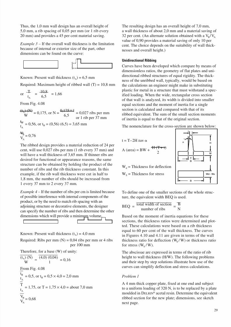
7/23/2019 f1236720 DuPont Engineering Polymers General Design Principles Module I
http://slidepdf.com/reader/full/f1236720-dupont-engineering-polymers-general-design-principles-module-i 31/155
Thus, the 1,0 mm wall design has an overall height of5,0 mm, a rib spacing of 0,05 per mm (or 1 rib every
20 mm) and provides a 45 per cent material saving.
Example 3 – If the overall wall thickness is the limitation
because of internal or exterior size of the part, other
dimensions can be found on the curve:
Known: Present wall thickness (tA) = 6,5 mm
Required: Maximum height of ribbed wall (T) = 10,8 mm
orT
=10,8
= 1,66tA 6,5
From Fig. 4.08
(tA) (N)
= 0,175, or N =
0,1751
= 0,027 ribs per mmW 6,5 or 1 rib per 37 mmtB = 0,56, or tB = (0,56) (6,5) = 3,65 mmtA
VB = 0,76VA
The ribbed design provides a material reduction of 24 per
cent, will use 0,027 ribs per mm (1 rib every 37 mm) andwill have a wall thickness of 3,65 mm. If thinner ribs are
desired for functional or appearance reasons, the same
structure can be obtained by holding the product of the
number of ribs and the rib thickness constant. In thisexample, if the rib wall thickness were cut in half to
1,8 mm, the number of ribs should be increased from
1 every 37 mm to 2 every 37 mm.
Example 4 – If the number of ribs per cm is limited because
of possible interference with internal components of the
product, or by the need to match rib spacing with anadjoining structure or decorative elements, the designer
can specify the number of ribs and then determine the other
dimensions which will provide a minimum volume.
Known: Present wall thickness (tA) = 4,0 mm
Required: Ribs per mm (N) = 0,04 ribs per mm or 4 ribsper 100 mm
Therefore, for a base (W) of unity:
(tA) (N)=
(4,0) (0,04)= 0,16
W 1
From Fig. 4.08
tB = 0,5, or tB = 0,5 × 4,0 = 2,0 mmtA
T = 1,75, or T = 1,75 × 4,0 = about 7,0 mmtA
VB = 0,68VA
The resulting design has an overall height of 7,0 mm,a wall thickness of about 2,0 mm and a material saving of
32 per cent. (An alternate solution obtained with a VB /VA
value of 0,90 provides a material saving of only 10 percent. The choice depends on the suitability of wall thick-
nesses and overall height.)
Unidirectional Ribbing
Curves have been developed which compare by means of
dimensionless ratios, the geometry of flat plates and uni-
directional ribbed structures of equal rigidity. The thick-ness of the unribbed wall, typically, would be based on
the calculations an engineer might make in substituting
plastic for metal in a structure that must withstand a spec-
ified loading. When the wide, rectangular cross sectionof that wall is analyzed, its width is divided into smaller
equal sections and the moment of inertia for a single
section is calculated and compared with that of its
ribbed equivalent. The sum of the small section momentsof inertia is equal to that of the original section.
The nomenclature for the cross-section are shown below:
t = T–2H tan
A (area) = BW +H (T+ t)
2
Wd = Thickness for deflection
WS = Thickness for stress
To define one of the smaller sections of the whole struc-
ture, the equivalent width BEQ is used.
BEQ =total width of section
=B
number of ribs N
Based on the moment of inertia equations for these
sections, the thickness ratios were determined and plot-ted. These calculations were based on a rib thickness
equal to 60 per cent of the wall thickness. The curvesin Figures 4.10 and 4.11 are given in terms of the wall
thickness ratio for deflection (Wd / W) or thickness ratiofor stress (WS / W).
The abscissae are expressed in terms of the ratio of ribheight to wall thickness (H/W). The following problems
and their step by step solutions illustrate how use of the
curves can simplify deflection and stress calculations.
Problem 1
A 4 mm thick copper plate, fixed at one end and subjectto a uniform loading of 320 N, is to be replaced by a plate
moulded in DELRIN® acetal resin. Determine the equivalent
ribbed section for the new plate; dimensions, see sketch
next page.
29

7/23/2019 f1236720 DuPont Engineering Polymers General Design Principles Module I
http://slidepdf.com/reader/full/f1236720-dupont-engineering-polymers-general-design-principles-module-i 32/155
30
Flex modulus for copper:EC = 105000 MPa
Flex modulus for DELRIN® acetal resin
ED = 3000 MPa
The wall thickness for a plate in DELRIN® acetal resin
with equivalent stiffness is calculated by equating
the product of the modulus and moment of inertia of
the two materials.
EC × WC3 = ED × Wd
3; or: 105000 × 43 = 3000 × Wd3
Thus: Wd = 13 mm.
Since a wall thickness of 13 mm is not ordinarily consid-
ered practical for plastic structures, primarily because of
processing difficulties, a ribbed section is recommended.Therefore, assume a more reasonable wall of 3 mm,
and compute for a plate with nine equally spaced ribs, rib
height, deflection and stress.
Wd
=
13
= 4,33W 3
BEQ =B
=100
=11,1BEQ
=11,1
= 3,7N 9 W 3
From the deflection graph (Fig. 4.10) we obtain:
H= 5,7 H = 5,7 × 3 = 17,1 mm
W
From the stress graph (Fig. 4.11) forH
= 5,7 andW
BEQ= 3,7 we obtain:
WWS = 2,75 WS = 2,75 × 3 mm = 8,25 mmW
Determine the moment of inertia and section modulus forthe ribbed area, equal to that of the solid plastic plate:
I = BW3
D=100 × 133
= 18300 mm4
12 12
Z =BW2
S =100 × 8,252
= 1130 mm3
6 6
Maximum deflection at the free end:
max =FL3
=320 × 250 3
= 11,4 mm8 EI 8 × 3000 × 18300
Maximum stress at the fixed end:
max =FL
=320 × 250
= 35,4 MPa2 Z 2 × 1130
Since DELRIN® acetal resin has a tensile strength valueof 69 MPa a safety factor of 2 is obtained.
Problem 2
Determine deflection and stress for a structure as shown
made of RYNITE® 530 thermoplastic polyester resin;
supported at both ends.
Substitute the known data:
BEQ =B
=60
= 15BEQ
=15
= 5N 4 W 3
H = 18 – 3 = 15H
=15
= 5W 3
From the graphs
Wd
= 3,6 Wd = 3,6 × 3 = 10,8W
WS = 2,25 WS = 2,25 × 3 = 6,75 mmW
I =BWd
3
=60 ×10,83
= 6300 mm4
12 12
Z =BWS
2
=60 × 6,752
= 455 mm3
6 6
max =5
×FL3
=5 × 667,2 × 5083
= 20 mm384 EI 384 × 9000 × 6300
max =FL
=667,2 × 508
= 93 MPa8 Z 8 × 455
The tensile strength of RYNITE® 530, measured on testbars,
is 158 MPa. The allowable stress for more complex partsdepends on the local glass-fibre orientation. Assuming a
good orientation for this problem, a reduction factor of 0,8
is realistic; thus the allowable stress = 0,8 × 158 = 126 MPa.
The applicable safety factor thus becomes:S = 126 / 93 = 1,35.
Remark: Ribs having a height exceeding 5 times their
thickness and subject to higher compression stresses,
should be checked on danger for buckling (instability).
667,2 N 60
1,8 mm3 mm
18 mm
1°
508 mm
250 mm
320 N
4 mm
100 mm
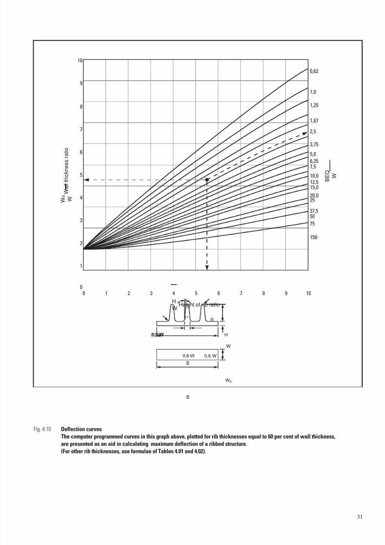
7/23/2019 f1236720 DuPont Engineering Polymers General Design Principles Module I
http://slidepdf.com/reader/full/f1236720-dupont-engineering-polymers-general-design-principles-module-i 33/155
31
Fig. 4.10 Deflection curves
The computer programmed curves in this graph above, plotted for rib thicknesses equal to 60 per cent of wall thickness,
are presented as an aid in calculating maximum deflection of a ribbed structure.
(For other rib thicknesses, use formulae of Tables 4.01 and 4.02).
H
W
1098765432100
1
2
3
4
0,62
1,0
1,25
1,87
2,5
3,75
5,0
6,257,5
10,0
12,515,0
20,025
37,550
75
150
5
6
7
8
9
10
Height of rib ratio
W d
W W
a l l t h i c k n e s s r a t i o
B E Q
W
B
B
0,6 W
0,03R H
R
W
Wd
1°
0,5 W
0,6 W
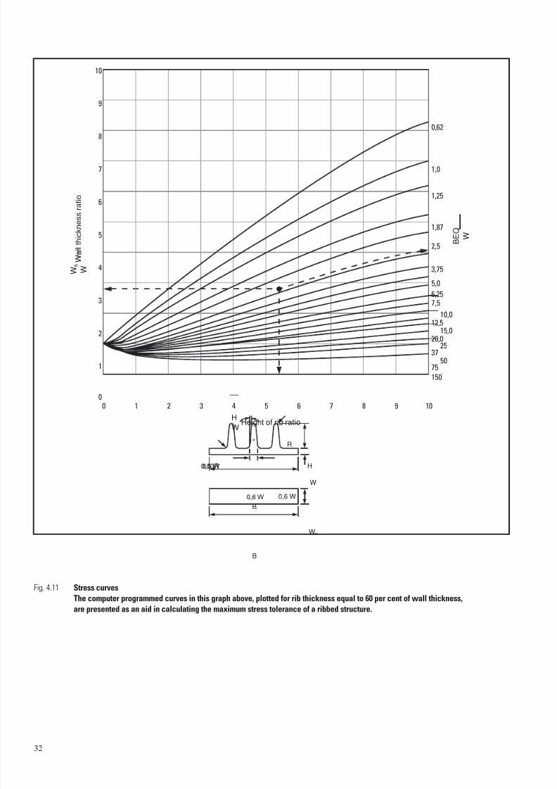
7/23/2019 f1236720 DuPont Engineering Polymers General Design Principles Module I
http://slidepdf.com/reader/full/f1236720-dupont-engineering-polymers-general-design-principles-module-i 34/155
32
Fig. 4.11 Stress curves
The computer programmed curves in this graph above, plotted for rib thickness equal to 60 per cent of wall thickness,
are presented as an aid in calculating the maximum stress tolerance of a ribbed structure.
1 2 3 4 5 6 7 8 9 10
0,62
1,0
1,25
1,87
2,5
3,75
5,0
6,25
7,5
10,012,5
15,020,0
2537
5075
150
0
10
9
8
7
6
5
4
3
2
1
0
B
B
0,6 W
0,03R H
R
W
Ws
1°
H
WHeight of rib ratio
W s W W
a l l t h i c k n e s s r a t i o
B E Q
W
0,5 W
0,6 W
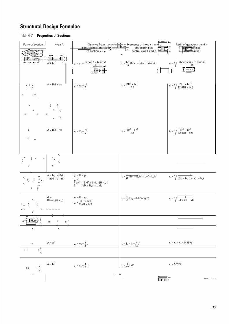
7/23/2019 f1236720 DuPont Engineering Polymers General Design Principles Module I
http://slidepdf.com/reader/full/f1236720-dupont-engineering-polymers-general-design-principles-module-i 35/155
33
Structural Design Formulae
Table 4.01 Properties of Sections
y1
y2
h
b
H
H
C
h
h
h
b2
b2
B2
B2
B
B
b
H
b y1
y2
H
H h h
B
B B
b H
y1
y2
h
b
b2b
2
A = bh y1
= y2
= h cos + b sin
2
y1 = y2 = H2
y1
= y2
= H2
y1
= y2
= 1 a2
I1
= I2
= I3
= 1 a4
12
y1 = H – y2
y2 =1 aH2 + B1d
2 + b1d1 (2H – d1)2 aH + B1d + b1d1
y1 = H – y2
y2 =aH2 + bd2
2(aH + bd)
I1
= bh (h2 cos2 + b2 sin2
)12
I1 = BH3 + bh3
12
r1 = (h2 cos2 + b2 sin2
)12
r1 = BH3 + bh3
12 (BH + bh)A = BH + bh
A = BH – bh
A = bd1 + Bd
+ a(H – d – d1)
I1 = BH3 – bh3
12
I1 = 1 (By3 – B1h3 + by3 – b1h
3)3 2 1 1
I1 = 1 (By3 – bh3 + ay3 )3 2 1
r1 = BH3 – bh3
12 (BH – bh)
r1 = I(Bd + bd1) + a(h + h1)
r1 = IBd + a(H – d)
Form of section Area A Distance fromcentroid to extremities
of section y1, y2
Moments of inertia I1 and I2about principal
central axis 1 and 2
Radii of gyration r1 and r2
about principal
central axes
H
B
d
h
d 1
h 1
b
B1
2
B1
2
b2
y1
y2
B
B B
b
a
b2
a2
b2
d
h
h H H
d
d
b
a
H
a2
y
y
1
2
d
A =
Bh – b(H – d)
A = a2
A = bd
y1
y2
a
a
1 1
y1
y2
d
b
1 1
y1 = y2 = 1 d2
I1 = 1 bd3
12
r1 = r2 = r3 = 0.289a
r1 = 0.289d

7/23/2019 f1236720 DuPont Engineering Polymers General Design Principles Module I
http://slidepdf.com/reader/full/f1236720-dupont-engineering-polymers-general-design-principles-module-i 36/155
34
y1
y2
d
b
1 1
A =1
bd 2
y 1 =2
d 3
y 2 =1
d
3
I 1 = d 3 (B 2 + 4Bb + b 2)36(B + b )
r1 =d 2(B 2 + 4Bb + b 2)
6(B + b )
Form of section Area A Distance from
centroid to extremities
of section y 1, y 2
Moments of inertia I 1 and I 2about principal
central axis 1 and 2
Radii of gyration r 1 and r 2about principal
central axes
y1
y2
d
B
b
1 1
A =1
(B + b )d 2
y 1 = d 2B + b
3(B + b )
y 2 = d B + 2b 3(B + b )
I 1 =1
bd 3
36r 1 = 0.2358d
R
R
A = R 2 y 1 = y 2 = R I =
1 R
4
4 r =
1R
2
R R0
1 1R0R
A = (R 2 – R 2)
0y 1 = y 2 – R I =
1 (R 4 – R 4)
40
R
2
2
1 1y1
y2
1
2
2
R 1y
1
y2
2
2
R
11
y1
y2
A =1
R 2
2
y 1 = 0.5756R
y 2 = 0.4244R
I 1 = 0.1098R 4
I 2 =1
R 48
r 1 = 0.2643R
r 2 =1
R 2
A = R 2
A =1
R 2 (22– sin 2)
I 1 =1
R 4 + sin cos 4
+ 2 sin3 cos
I 1 = R 4 + sin cos 4
I 2 =1
R 4 – sin cos 4
–16 sin6
9( – sin cos
– 16 sin2 9
r 1 =
1R 1 + sin cos 16 sin2
2 92
y 1 = R 1 –4 sin3 6 – 3 sin 2
R 4 sin3 – cos 6 – 3 sin 2
y 2 =
r 2 = 1R 1 –
2 sin3 cos 2 3( – sin cos )
r 2 = 1R 1 –sin cos
2
r 2 =1
R 1 +2 sin3 cos
2 – sin cos
–64 sin6
9(2 – sin 2)2
– 2 sin3 cos
I 2 = R 4 3 – 3 sin cos 12
R
t
R
2
2
R1
t
1
y1
y2
A = 2 Rt
A = (2 R-t ) t
y 1 = y 2 = R I = R 3 t r = 0.707R
y 1 = R 1 –2 sin 3
y 2 = 2R sin
3
y 1 = R 1 – sin + t 2
y 2 = 2R sin – cos +
t cos
2
I 1 =R 3 t + sin cos
I 2 =R 3 t ( – sin cos )
r 1 =
R + sin cos – 2 sin2 / 2
r 2 = R – sin cos 2
(1) Circular sector(2) Very thin annulus(3) Sector of thin annulus
(1)
(2)
(3)
– 2 sin2 + Rt 3
6
Thin wall
(for thick wall:
see “Roark & Young”
r =
(R 2 + R 2)
01
4

7/23/2019 f1236720 DuPont Engineering Polymers General Design Principles Module I
http://slidepdf.com/reader/full/f1236720-dupont-engineering-polymers-general-design-principles-module-i 37/155
35
Table 4.02 Shear, Moment, and Deflection Formulae for Beams; Reaction Formulae for Rigid Frames
Notation: W = load (N); w = unit load (N/linear mm); M is positive when clockwise; V is positive when upward; y is positive when upward.
Constraining moments, applied couples, loads, and reactions are positive when acting as shown. All forces are in N, all moments in N · mm;
all deflections and dimensions in mm. is in radians, I = moment of inertia of beam cross section (mm4).
l
x
y
WY
O B X
A
R 2 = + W
V = – W
M = –Wx
Max M = –W l at B
Loading, supportand reference
number
Reactions R 1 and R 2,vertical shear V
Bending moment M and maximum bending
moment
Deflection y , maximum deflection,and end slope
l
WY
O
C X
A B
b a
R 2 = + W
(A to B) V = 0
(B to C) V = – W
y = 1 W (x 3 – 3l
2 x + 2l3)
6 El
Max y = –1 Wl 3
at A3 El
= + 1 Wl2
at A2 El
l
Y
O
B
X
A
W = wl
R 2 = + W
V = – W x l
(A to B) M = 0
(B to C) M = –W(x – b) Max M = –Wa at C
M = M 0
Max M = M 0 (A to B)
(A to B) M = 0
(B to C) M = M 0
Max M = M 0 (B to C)
(A to B) M = + 1 Wx 2
(B to C) M = + 1W (l – x)
2
Max M = + 1W l at B
4
(A to B) y = –1 W
(–a 3 + 3a 2l – 3a 2x )
6 El
l
YA
M0
BX
O
R 2 = 0
V = 0
l
YA
a
B
M0
CX
O
Bl
YA W C
XO
l 2
R 2 = 0
V = 0
M = –1 W x 22 l
R 1 = + 1 W 2
R 2 = + 1 W 2
(A to B) V = + 1 W
2
(B to C) V = –1
W 2
(B to C) y = –1 W
(x – b) 3 – 3a 2 (x – b ) + 2a 36 El
Max y = –1 W (3a 2l – a3)6 El
= + 1 Wa 2 (A to B)2 El
y = –1 W (x 4 – 4l 3 x + 3l 4)24 El l
Max y = –1 Wl 3
8 El
Cantilever end load
Cantilever,
intermediate load
Cantilever,uniform load
Cantilever,end couple
Cantilever,intermediate couple
Max M = –1 W l at B2
= + 1 W l 2at A
6 El
y = 1 M 0 (l 2 – 2l x + x 2)2 El
Max y = + 1 M 0l2
at A2 El
(A to B)
y = M 0a l – 1 a – x El 2
(B to C)
y = 1 M 0 (x – l + a )2 – 2a (x – l + a ) + a 22 El
(A to B) y = –1 W (3l
2 x – 4x 3)48 El
Max y = M 0a l – 1a at A
El 2
= – M 0a (A to B)
El
Max y = –1 W l 3
at B48 El
= –1 W l 2
at A,16 El
= + 1 W l 2
at C16 El
= – M 0l at A
El
End supports,center load
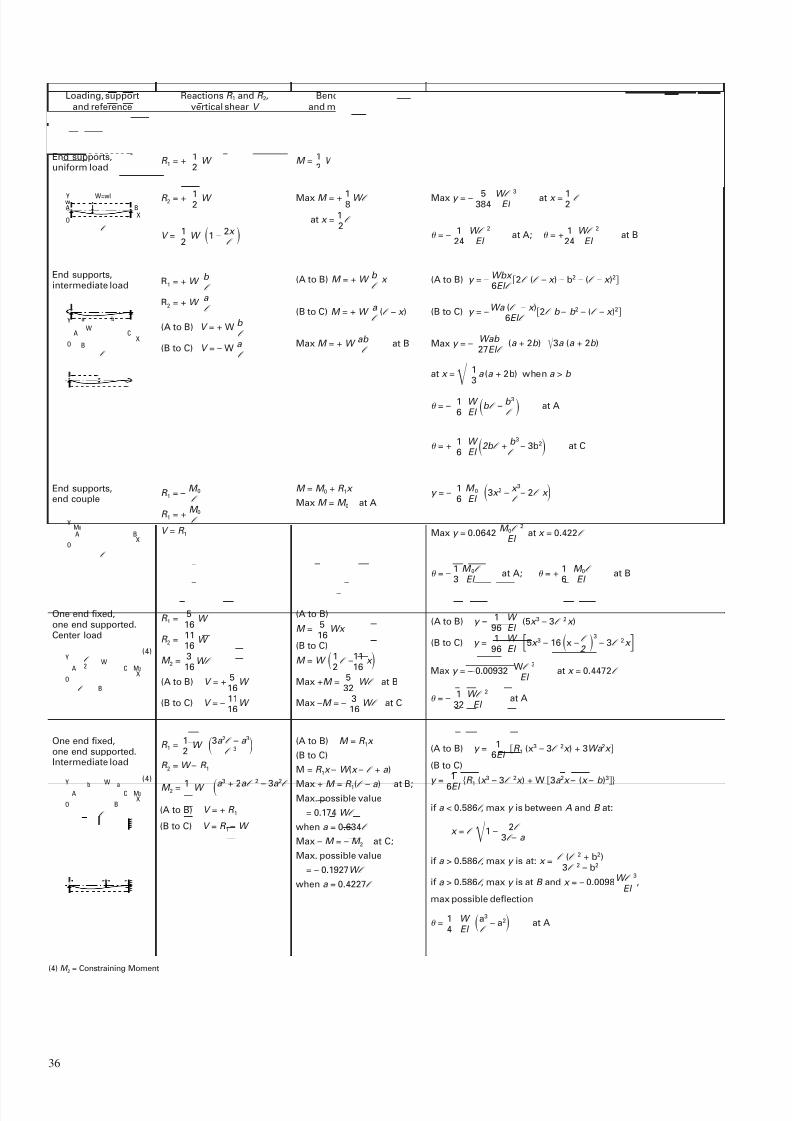
7/23/2019 f1236720 DuPont Engineering Polymers General Design Principles Module I
http://slidepdf.com/reader/full/f1236720-dupont-engineering-polymers-general-design-principles-module-i 38/155
36
l
Y
Aw
BX
O
W=wl
R 1 = + 1 W 2
R 2 = + 1 W 2
V = 1W 1 –
2x 2 l
M = 1W x –
x 2
2 l
Loading, support
and reference
number
Reactions R 1 and R 2,
vertical shear V
Bending moment M
and maximum bending
moment
Deflection y , maximum deflection,
and end slope
l
Y
A
a b
WC
XBO
R1 = + W b l
R2 = + W a l
(A to B) V = + W b l
(B to C) V = – W a l
y = –1 Wx (l 3 – 2l x 2 + x 3)24 El l
l
Y
BX
O
AM0
(A to B) M = + W b x l
(B to C) M = + W a (l – x )l
Max M = + W ab at Bl
(A to B) y = – Wbx 2l (l – x ) – b2 – (l – x )26El l
B
W
l
Y
XO
CA M2
l 2
l
B
Y W
XO
CAb a
M2
(B to C) y = –Wa (l – x )2l b – b 2 – (l – x )2
6El l
Max y = – Wab (a + 2b ) 3a (a + 2b )27El l
End supports,uniform load
End supports,intermediate load
End supports,end couple
One end fixed,one end supported.Center load
One end fixed,one end supported.Intermediate load
(A to B) y = 1 W (5x 3 – 3l2x )
96 El
(B to C) y = 1 W 5x 3 – 16 x –l
3
– 3l 2x 96 El 2
Max M = + 1 W l 8
at x = 1l
2
Max y = – 5 W l3
at x = 1 l 384 El 2
= –1 W l 2
at A; = + 1 W l 2
at B24 El 24 El
R 1 = – M 0l
R 1 = + M 0l
V = R 1
M = M 0 + R 1x
Max M = M 0 at A
(A to B)
M = 5 Wx 16
(B to C)
M = W 1l –
11 x 2 16
Max +M = 5W l at B
32
Max –M = –3 W l at C16
at x = 1 a (a + 2b) when a > b 3
= –1 W b l – b 3 at A6 El l
= + 1 W 2b l + b 3– 3b2 at C
6 El l
y = –1 M 0 3x 2 –
x 3– 2l x 6 El l
R 1 = 5W
16
R 2 = 11W
16
M 2 = 3W l
16
(A to B) V = + 5W
16
(B to C) V = –11W 16
Max y = 0.0642 M 0l
2
at x = 0.422l El
= –1 M 0l at A; = +
1 M 0l at B3 El 6 El
(A to B) M = R 1x
(B to C)
M = R 1x – W (x – l + a )
Max + M = R 1(l – a ) at B;Max. possible value
= 0.174 W l
when a = 0.634l
Max – M = – M 2 at C;
Max. possible value
= – 0.1927W l
when a = 0.4227l
R 1 = 1W 3a 2l – a 32 l
3
R 2 = W – R 1
(A to B) V = + R 1
(B to C) V = R 1 – W
M 2 = 1 W a 3
+ 2a l2 –
3a 2
l
Max y = – 0.00932 Wl 3
at x = 0.4472l El
= –1 W l 2
at A32 El
(A to B) y = 1 R 1 (x3 – 3l 2x ) + 3Wa 2x 6El
(B to C)
y = 1 R 1
(x 3 – 3l 2x ) + W 3a 2x – (x – b )36El
if a < 0.586l , max y is between A and B at:
if a > 0.586l , max y is at: x = l (l 2 + b2)3l 2 – b2
if a > 0.586l , max y is at B and x = – 0.0098W l 3
,El
max possible deflection
= 1 W a3
– a2 at A4 El l
x = l 1 –2l
3l – a
(4)
(4)
(4) M 2 = Constraining Moment
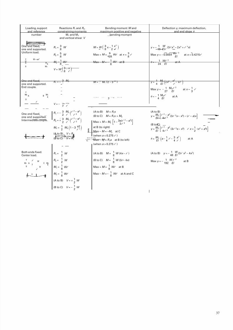
7/23/2019 f1236720 DuPont Engineering Polymers General Design Principles Module I
http://slidepdf.com/reader/full/f1236720-dupont-engineering-polymers-general-design-principles-module-i 39/155
37
Y
Aw
BX
O
W = wl
M2
R 1 = 3 W 8
R 2 = 5 W
8M 2 = 1 W l
8
V = W 3– x 8 l
M = W 3 x –1 x 2 8 2 l
Loading, support
and reference
number
Reactions R 1 and R 2,
constraining moments
M1 and M2
and vertical shear V
Bending moment M and
maximum positive and negative
bending moment
Deflection y , maximum deflection,
and end slope
l
Y
A BM0
X
O
M2
R 1 = –3 M 02 l
R 2 = + 3 M 02 l
M 2 = 1 M 02
V = –3 M 02 l
y = –1 W (3l x 3 – 2x 4 + l 3x )48 El l
l
Y
A CX
O
M2M0
B
a
M = 1 M 0 2 – 3 x 2 l
Max + M = M 0 at A
Max – M = 1 M 0 at B2
y = 1 M 0 2x 2 – x 3
– x l 4 El l
l
B
WY
XO
CA M2M1
l
2
One end fixed,one end supported.Uniform load.
One end fixed,one end supported.End couple.
One end fixed,one end supported.Intermediate couple.
Both ends fixed.Center load.
(A to B) y = –1 W (3l x 2 – 4x 3)48 El
Max y = –1 W l 3
at B192 El
Max + M = 9 W l at x = 3l
128 8Max – M = –
1 W l at B8
Max y = – 0.0054 W l 3
at x = 0.4215l
El
= –1 W l 2
at A24 El
R 1 = –3 M 0
l2 – a2
2 l l
2
R 2 = + 3 M 0 l2 – a2
2 l l 2
M 2 = 1 M 0 1 – 3 a2 2 l2
(A to B) V = R 1
(B to C) V = R 1
(A to B) M = R 1x
(B to C) M = R 1x + M 0
Max + M = M 0 1 –3a(l 2 – a2)2l
3
at B (to right)
Max – M = –M 2 at C
(when a < 0.275 l )
Max – M = R 1a at B (to left)
(when a > 0.275 l )
(A to B) M = 1 W (4x – l )8
(B to C) M = 1 W (3l – 4x )8
Max + M = 1 W l at B8
Max – M = – 1 W l at A and C8
(A to B)
y = M 0 l2 –
a 2
(3l 2x – x 3) – (l – a )x El 4l 3
R 1 = 1W
2
R 2 = 1W
2
M 1 = 1W l
8
M 2 = 1 W l 8
(A to B) V = + 1W
2
(B to C) V = –1
W 2
Max y = –1 M0l
2
at x = 1l
27 El 3
= –1 M0l at A4 El
(B to C)
y = M 0 l2 – a 2 (3l 2x – x 3) – l x + 1 (x 2 + a 2)El 4l 3 2
= M 0 a –1
l –3 a 2 at A
El 4 4 l
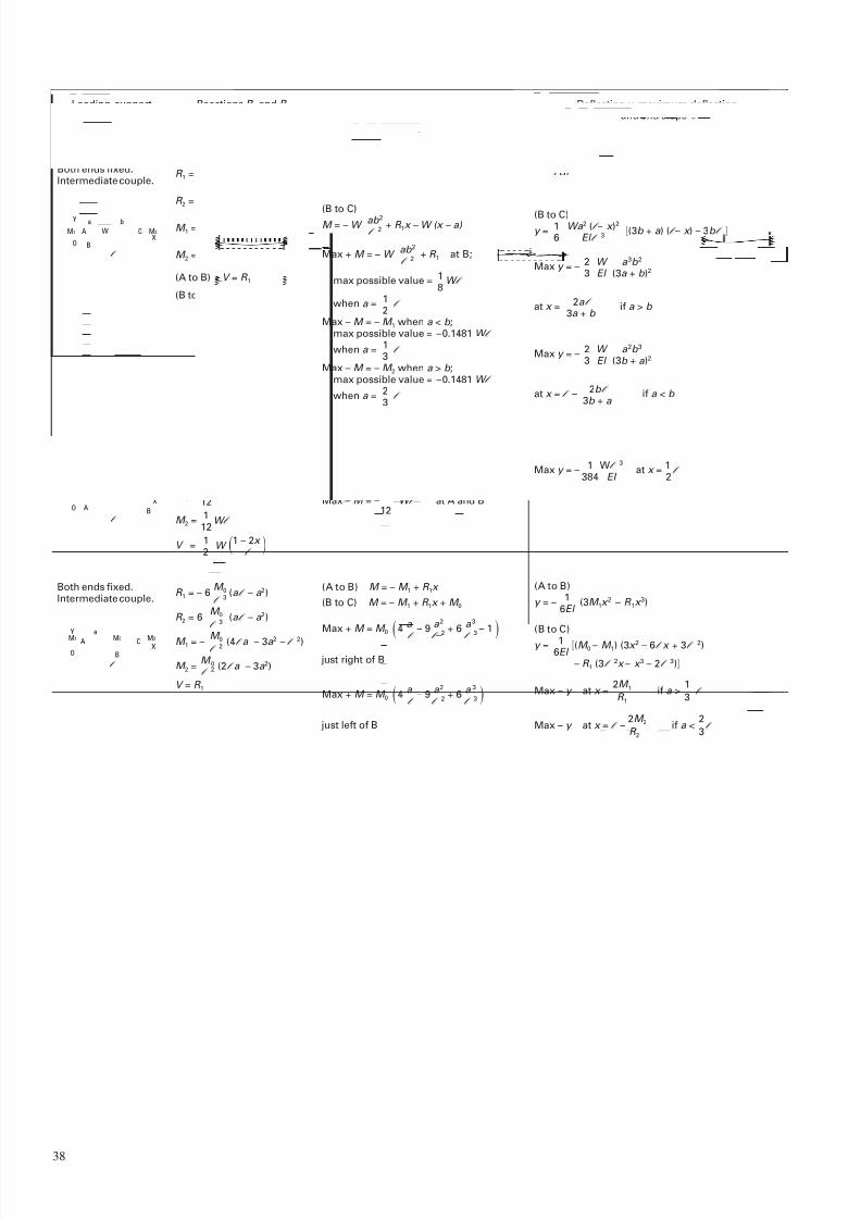
7/23/2019 f1236720 DuPont Engineering Polymers General Design Principles Module I
http://slidepdf.com/reader/full/f1236720-dupont-engineering-polymers-general-design-principles-module-i 40/155
38
l
B
W
Y
XO
CA
a b
M2M1
R 1 = Wb 2 (3a + b )l 3
R 2 = Wa 2 (3b + a )l
3
M 1 = W ab 2
l 2
M 2 = W a 2b l 2
(A to B) V = R 1
(B to C) V = R 1 – W
(A to B)
M = – W ab 2 + R 1x l 2
Loading, supportand reference
number
Reactions R 1 and R 2,constraining moments
M1 and M2
and vertical shear V
Bending moment M andmaximum positive and negative
bending moment
Deflection y , maximum deflection,and end slope
l
Y
A B
XO
W = wl
M1 M2
R 1 = 1W
2
R 2 = 1W
2
M 1 = 1W l
12
M 2 = 1W l
12
V = 1W 1 – 2x 2 l
(A to B)
y = 1 Wb 2x 2 (3ax + bx – 3a l )6 El l 3
l
Y
CA XO
M2M0M1
B
a
M = 1 W x – x 2–
1l 2 l 6
Max + M = 1 W l at x = 1l
24 2
Max – M = –1 W l at A and B12
y = 1 Wx 2 (2l x – l 2 – x 2)24 El l
Both ends fixed.Intermediate couple.
Both ends fixed.Uniform load.
Both ends fixed.Intermediate couple.
R 1 = – 6 M 0 (a l – a 2)l
3
R 2 = 6 M 0 (a l – a 2)l
3
M 1 = – M 0 (4l a – 3a 2 – l 2)l 2
M 2 = M 0 (2l a – 3a 2)l
2
V = R 1
(A to B) M = – M 1 + R 1x
(B to C) M = – M 1 + R 1x + M 0
Max + M = M 0 4 a – 9 a 2 + 6 a 3
– 1 l l
2l
3
(A to B)
y = –1 (3M 1x 2 – R 1x 3)
6El
(B to C)
y = 1 (M 0 – M 1) (3x 2 – 6l x + 3l 2)6El
– R 1 (3l 2x – x 3 – 2l 3)
Max y = –1 Wl 3
at x = 1l
384 EI 2
(B to C)M = – W
ab 2 + R 1x – W (x – a) l 2
Max + M = – W ab 2 + R 1 at B;l 2
max possible value = 1 W l 8
when a = 1l
2Max – M = – M 1 when a < b ;
max possible value = –0.1481 W l
when a = 1l
3Max – M = – M 2 when a > b ;
max possible value = –0.1481 W l
when a = 2l
3
(B to C)
y = 1 Wa 2 (l – x )2
(3b + a ) (l – x ) – 3b l 6 El l 3
Max y = –2 W a 3b 2
3 El (3a + b )2
Max y = –2 W a 2b 3
3 El (3b + a )2
at x = l –2b l if a < b
3b + a
at x = 2a l if a > b 3a + b
Max + M = M 0 4 a – 9 a 2 + 6 a 3
l l 2 l 3
just right of B
just left of B
Max – y at x =2M 1 if a >
1l
R 1 3
Max – y at x = l –2M 2 if a <
2l
R 2 3

7/23/2019 f1236720 DuPont Engineering Polymers General Design Principles Module I
http://slidepdf.com/reader/full/f1236720-dupont-engineering-polymers-general-design-principles-module-i 41/155
39
Table 4.03 Formulae for Torsional Deformation and Stress
General formulae: =M T l , =
M T , where = angle of twist (rad); M T = twisting moment (N · mm);KG Q
l = length (mm); = unit shear stress (MPa); G = shear modulus (MPa); K (mm4) is a function of the cross section.
Form an dimensions of cross sections
Solid circular section
Formula for K in =M T l
KG
K = 1r 4
2
Formula for shear stress
Max =2M T at boundary r 3
2r
Solid elliptical section
2 b
2a
K = a 3b 3
a 2 + b 2Max =
2M T at ends ab 2
for minor axis
Solid square section
a
K = 0.1406a 4 Max =M T at mid-point
0.208a
3
of each side
Solid rectangular section
Hollow concentric circular section
r1
r0
K = 1 (r 4 – r 4)
2 1 0 Max =2M T r1 at outer boundary
(r4 – r4)1 0
t
K = 1Ut 3
2Max =
M T (3U + 1.8t ), along both edges
U 2t 2
remote from ends (this assumes t small compared
with least radius of curvatore of median line)
Any thin open tube of uniform thicknessU = length of median line, shown dotted
a
b
K = a 3b 1 – 0.28 a 1 – a 4 3 b 12b 4Max =
M T (1.8a + 3.0b )at mid-point
a 2b 2of longer edges
(b ≥ a)
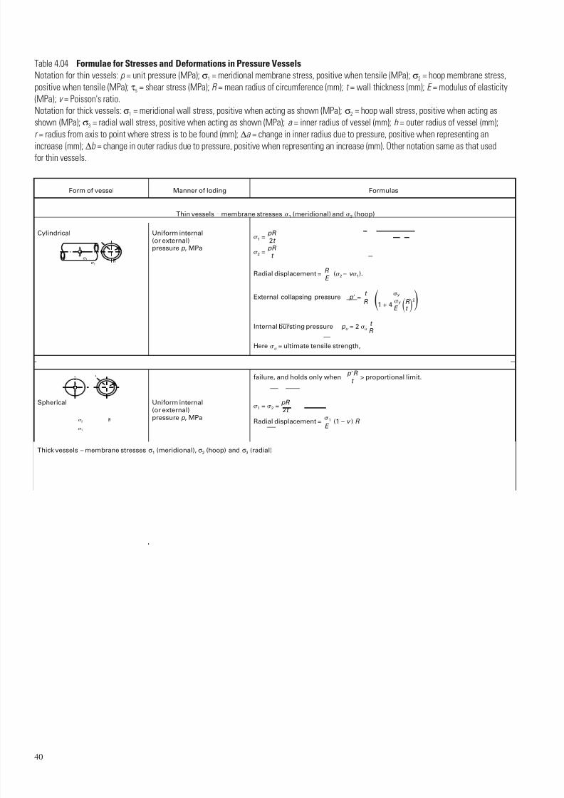
7/23/2019 f1236720 DuPont Engineering Polymers General Design Principles Module I
http://slidepdf.com/reader/full/f1236720-dupont-engineering-polymers-general-design-principles-module-i 42/155
40
Table 4.04 Formulae for Stresses and Deformations in Pressure Vessels
Notation for thin vessels: p = unit pressure (MPa); σ1 = meridional membrane stress, positive when tensile (MPa); σ2 = hoop membrane stress,
positive when tensile (MPa); τs = shear stress (MPa); R = mean radius of circumference (mm); t = wall thickness (mm); E = modulus of elasticity
(MPa); v = Poisson's ratio.
Notation for thick vessels: σ1 = meridional wall stress, positive when acting as shown (MPa); σ2 = hoop wall stress, positive when acting as
shown (MPa); σ3 = radial wall stress, positive when acting as shown (MPa); a = inner radius of vessel (mm); b = outer radius of vessel (mm);
r = radius from axis to point where stress is to be found (mm); ∆a = change in inner radius due to pressure, positive when representing an
increase (mm); ∆b = change in outer radius due to pressure, positive when representing an increase (mm). Other notation same as that used
for thin vessels.
Form of vessel
Cylindrical
Spherical
Torus
Manner of loding
Uniform internal(or external)pressure p , MPa
Uniform internal(or external)
pressure p , MPa
Complete torusunder uniform internalpressure p , MPa
1 = pR 2t
2 = pR
t
Radial displacement = R (2 – v 1).
E
External collapsing pressure p = t
y
R 1 + 4y R
2
E t
Internal bursting pressure p u = 2 u t R
Here u = ultimate tensile strength,
where y = compressive yield point of material. This formula is for nonelastic
failure, and holds only when p R
> proportional limit.t
1 = 2 = pR 2t
Radial displacement = 1 (1 – v ) R E
1 = pb 1 + a t 2r
Max 1 = pb 2a – b at 0
t 2a – 2b
2 = pR
(uniform throughout)2t
Formulas
Thin vessels – membrane stresses 1 (meridional) and 2 (hoop)
t
2
1R
2
1
R
O
t
r a b
1
Thick vessels – membrane stresses σ1 (meridional), σ2 (hoop) and σ3 (radial)
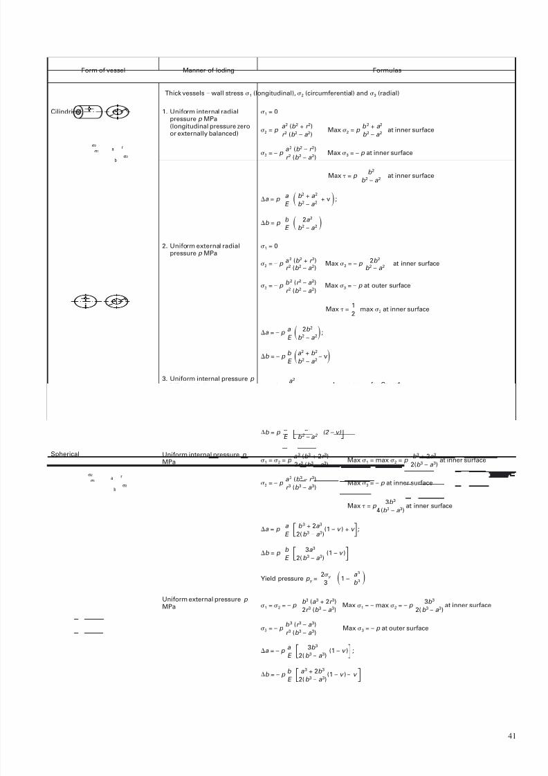
7/23/2019 f1236720 DuPont Engineering Polymers General Design Principles Module I
http://slidepdf.com/reader/full/f1236720-dupont-engineering-polymers-general-design-principles-module-i 43/155
41
Form of vessel
Cilindrical
Manner of loding
1. Uniform internal radialpressure p MPa(longitudinal pressure zero
or externally balanced)
2. Uniform external radialpressure p MPa
3. Uniform internal pressure p MPa in all directions(ends capped)
Uniform internal pressure p MPa
Uniform external pressure p MPa
1 = 0
2 = p a 2 (b 2 + r 2)
Max 2 = p b 2 + a 2
at inner surface
r 2
(b 2 –
a 2
) b 2 –
a 2
3 = – p a 2 (b 2 – r 2)
Max 3 = – p at inner surfacer 2 (b 2 – a 2)
Max = p b 2
at inner surfaceb 2 – a 2
a = p a b 2 + a 2
+ v ;E b 2 – a 2
b = p b 2a 2 E b 2 – a 2
Formulas
Thick vessels – wall stress 1 (longitudinal), 2 (circumferential) and 3 (radial)
σ2
σ1
σ3
ra
b
Spherical
σ2
σ1
σ3
ra
b
1 = 2 = p a 3 (b 3 + 2r 3)
Max 1 = max 2 = p b 3 + 2a 3
at inner surface2r 3 (b 3 – a 3) 2(b 3 – a 3)
3 = – p a 3 (b 3 – r 3)
Max 3 = – p at inner surfacer 3 (b 3 – a 3)
Max = p 3b 3
at inner surface4(b 3 – a 3)
a = p a b 3 + 2a 3
(1 – v ) + v ;E 2(b 3 – a 3)
b = p b 3a 3
(1 – v )E 2(b 3 – a 3)
Yield pressure p y =2y 1 –
a 3 3 b 3
1 = 0
2 = – p a 2 (b 2 + r 2) Max 2 = – p 2b 2 at inner surfacer 2 (b 2 – a 2) b 2 – a 2
3 = – p b 2 (r 2 – a 2) Max 3 = – p at outer surfacer 2 (b 2 – a 2)
Max =1
max 2 at inner surface2
a = – p a 2b 2 ;E b 2 – a 2
b = – p b a 2 + b 2
– vE b 2 – a 2
1 = p a 2
, 2 and 3 same as for Case 1.b 2 – a 2
a = p a b
2
+ a
2
– v a
2
– 1 ;E b 2 – a 2 b 2 – a 2
b = p b a 2
(2 – v) E b 2 – a 2
1 = 2 = – p b 3 (a 3 + 2r 3)
Max 1 = – max 2 = – p 3b 3
at inner surface2r 3 (b 3 – a 3) 2(b 3 – a 3)
3 = – p b 3 (r 3 – a 3)
Max 3 = – p at outer surfacer 3 (b 3 – a 3)
a = – p a 3b 3
(1 – v ) ;E 2(b 3 – a 3)
b = – p b
a 3 + 2b 3(1 – v ) – v
E 2(b 3– a 3)

7/23/2019 f1236720 DuPont Engineering Polymers General Design Principles Module I
http://slidepdf.com/reader/full/f1236720-dupont-engineering-polymers-general-design-principles-module-i 44/155
42
Table 4.05 Buckling of Columns, Rings and Arches
E = modulus of elasticity, I = moment of inertia of cross section about central axis perpendicular to plane of buckling. All dimensions are in mm,
all forces in N, all angles in radians.
Form of bar;manner of loading and support
Uniform straight bar under end loadOne end free, other end fixed
F c = 2 El 4 l 2
Formulas for critical load F c , or critical unit load q c
l
F
Uniform straight bar under end loadBoth ends hinged
l
F
F
0.7l
0.3l
F c =2 El l
2
F c = 2 El (0.7 l ) 2
Uniform straight bar under end loadOne end fixed, other end hinged andhorizontally constrained over fixed end
q
r
q c = 3 El
r 2
Uniform circular ring under uniform radialpressure q N•m. Mean radius of ring r .
2
q
q c = El 2
– 1 r 3 2
Uniform circular arch under uniform radialpressure q . Mean radius r .Ends hinged
2
q
q c = El (k 2 – 1)
r 3
Uniform circular arch under uniform radialpressure q . Mean radius r .Ends fixed
Where k depends on and is found by trial from the equation: k tan cot k = 1 or from the followingtable:
= 15° 30° 45° 60° 75° 90° 120° 180°
k = 17.2 8.62 5.80 4.37 3.50 3.00 2.36 2.00
l
l
0,7 l
0,3 l
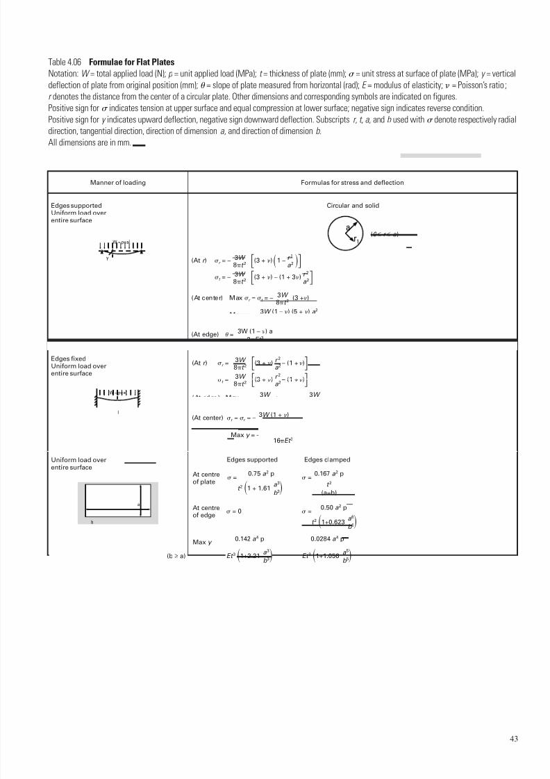
7/23/2019 f1236720 DuPont Engineering Polymers General Design Principles Module I
http://slidepdf.com/reader/full/f1236720-dupont-engineering-polymers-general-design-principles-module-i 45/155
43
Table 4.06 Formulae for Flat Plates
Notation: W = total applied load (N); p = unit applied load (MPa); t = thickness of plate (mm); = unit stress at surface of plate (MPa); y = vertical
deflection of plate from original position (mm); = slope of plate measured from horizontal (rad); E = modulus of elasticity; = Poisson’s ratio ;
r denotes the distance from the center of a circular plate. Other dimensions and corresponding symbols are indicated on figures.
Positive sign for indicates tension at upper surface and equal compression at lower surface; negative sign indicates reverse condition.
Positive sign for y indicates upward deflection, negative sign downward deflection. Subscripts r, t, a, and b used with denote respectively radial
direction, tangential direction, direction of dimension a, and direction of dimension b .
All dimensions are in mm.
Manner of loading
Edges supportedUniform load overentire surface
Formulas for stress and deflection
Y
W = pa2
Circular and solid
(At r ) r = – 3W (3 + )1 – r 2
8t 2 a 2
t = – 3W (3 + ) – (1 + 3) r 2 8t 2 a 2
(At center) Max r = t = – 3W (3 +)8t 2
Max y = –3W (1 – ) (5 + ) a 2
16Et 3
r1
a
Edges fixedUniform load overentire surface
l
W = pa2
(At r ) r =3W (3 + ) r
2
– (1 +)8t 2 a 2
t =3W (3 + ) r
2
– (1 +)8t 2 a 2
(At edge) Max r =3W ; t =
3W 4t 2 4t 2
(At edge) =3W (1 – ) a
2Et 3
(At center) r = r = – 3W (1 + )8t 2
Max y = –3W (1 – 2) a 2
16Et 3
(0 ≤ r ≤ a )
Uniform load overentire surface
(b ≥ a)
=0.50 a 2 p
t 2 1+0.623 a 6b 6
= 0
0.142 a 4 p
Et 3 1+2.21 a 3b 3
0.0284 a 4 p
Et 3 1+1.056 a 5b 5
=0.167 a 2 p
t 2
(a=b)
=0.75 a 2 p
t 2 1 + 1.61 a 3b 3
Max y
At centreof plate
Edges supported Edges clamped
At centreof edge
b
a
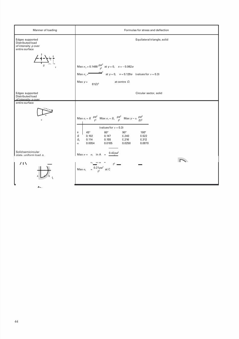
7/23/2019 f1236720 DuPont Engineering Polymers General Design Principles Module I
http://slidepdf.com/reader/full/f1236720-dupont-engineering-polymers-general-design-principles-module-i 46/155
44
Manner of loading Formulas for stress and deflection
Equilateral triangle, solid
Circular sector, solid
Edges supportedDistributed loadof intensity p overentire surface
1/3a
y
a
O
X
O
a
Edges supportedDistributed loadof intensity p overentire surface
A C
C
B
L
Solid semicircularplate, uniform load p ,all edges fixed
Max r = ß pa 2
Max 1 = ß 1pa 2
Max y =
pa 4
t 2 t 2 Et 2
(values for = 0.3)
45° 60° 90° 180°
ß 0.102 0.147 0.240 0.522
ß 1 0.114 0.155 0.216 0.312
0.0054 0.0105 0.0250 0.0870
Max = r in A =0.42pa 2
t 2
r in B =0.36pa 2
t 2
Max t =0.21pa 2
at Ct 2
Max x = 0.1488 pa 2
at y = 0, x = – 0.062a t 2
Max y = 0.1554 pa 2
at y = 0, x = 0.129a (values for = 0.3)t 2
Max y = pa 4 (1 – 2)
at centre O .81Et 3
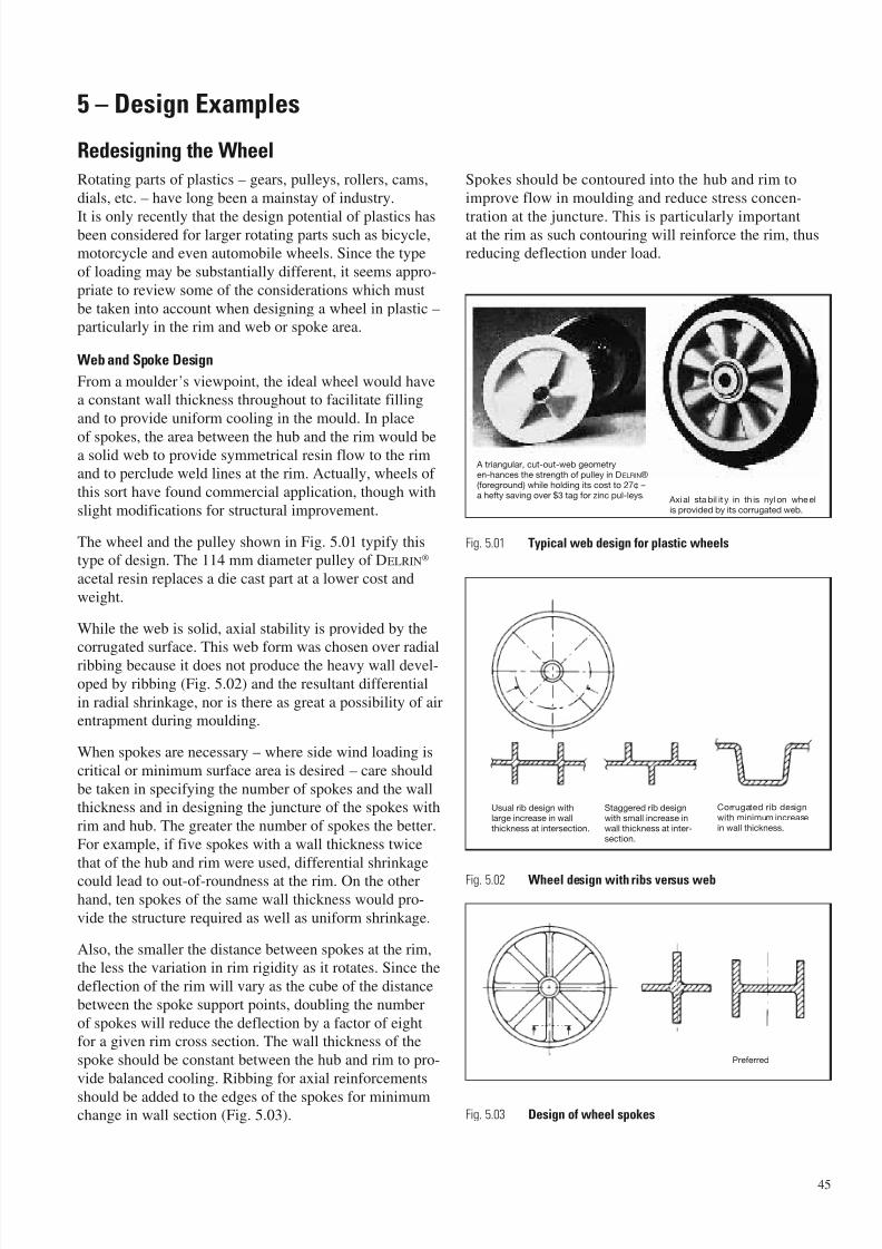
7/23/2019 f1236720 DuPont Engineering Polymers General Design Principles Module I
http://slidepdf.com/reader/full/f1236720-dupont-engineering-polymers-general-design-principles-module-i 47/155
5 – Design Examples
Redesigning the Wheel
Rotating parts of plastics – gears, pulleys, rollers, cams,
dials, etc. – have long been a mainstay of industry.
It is only recently that the design potential of plastics hasbeen considered for larger rotating parts such as bicycle,
motorcycle and even automobile wheels. Since the type
of loading may be substantially different, it seems appro-
priate to review some of the considerations which must
be taken into account when designing a wheel in plastic –
particularly in the rim and web or spoke area.
Web and Spoke Design
From a moulder’s viewpoint, the ideal wheel would havea constant wall thickness throughout to facilitate filling
and to provide uniform cooling in the mould. In place
of spokes, the area between the hub and the rim would bea solid web to provide symmetrical resin flow to the rimand to perclude weld lines at the rim. Actually, wheels of
this sort have found commercial application, though with
slight modifications for structural improvement.
The wheel and the pulley shown in Fig. 5.01 typify thistype of design. The 114 mm diameter pulley of DELRIN®
acetal resin replaces a die cast part at a lower cost and
weight.
While the web is solid, axial stability is provided by thecorrugated surface. This web form was chosen over radial
ribbing because it does not produce the heavy wall devel-
oped by ribbing (Fig. 5.02) and the resultant differential
in radial shrinkage, nor is there as great a possibility of airentrapment during moulding.
When spokes are necessary – where side wind loading is
critical or minimum surface area is desired – care should
be taken in specifying the number of spokes and the wallthickness and in designing the juncture of the spokes with
rim and hub. The greater the number of spokes the better.
For example, if five spokes with a wall thickness twice
that of the hub and rim were used, differential shrinkage
could lead to out-of-roundness at the rim. On the otherhand, ten spokes of the same wall thickness would pro-
vide the structure required as well as uniform shrinkage.
Also, the smaller the distance between spokes at the rim,the less the variation in rim rigidity as it rotates. Since the
deflection of the rim will vary as the cube of the distance
between the spoke support points, doubling the number
of spokes will reduce the deflection by a factor of eightfor a given rim cross section. The wall thickness of the
spoke should be constant between the hub and rim to pro-
vide balanced cooling. Ribbing for axial reinforcements
should be added to the edges of the spokes for minimumchange in wall section (Fig. 5.03).
Spokes should be contoured into the hub and rim to
improve flow in moulding and reduce stress concen-
tration at the juncture. This is particularly importantat the rim as such contouring will reinforce the rim, thusreducing deflection under load.
45
A triangular, cut-out-web geometryen-hances the strength of pulley in DELRIN®(foreground) while holding its cost to 27¢ –a hefty saving over $3 tag for zinc pul-leys. Axial sta bil it y in th is nyl on whe el
is provided by its corrugated web.
Usual rib design withlarge increase in wallthickness at intersection.
Staggered rib designwith small increase inwall thickness at inter-section.
Corrugated rib designwith minimum increasein wall thickness.
Preferred
Fig. 5.01 Typical web design for plastic wheels
Fig. 5.02 Wheel design with ribs versus web
Fig. 5.03 Design of wheel spokes

7/23/2019 f1236720 DuPont Engineering Polymers General Design Principles Module I
http://slidepdf.com/reader/full/f1236720-dupont-engineering-polymers-general-design-principles-module-i 48/155
Rim Design
Rim design requirements will vary depending upon
whether or not a tire is used and whether the tire is solid
or pneumatic.
Tireless wheels are frequently used on material handling
equipment where vibration and noise are not critical.
Impact resistance is of prime importance in this type of
service, and rims are frequently moulded with wall thick-
ness up to 9,5 mm. The lengthened moulding cycle can
increase processing costs to a point where it can be more
economical to mould a wheel in a thinner wall and –
using the wheels as an insert – mould an elastomeric tire
around it.
If a pneumatic tire is used, the rim will be under constant
pressure and the effect of creep on rim geometry must be
taken into account. It can be shown that the outward force
exerted on the rim is a product of the pressure in the
tire and the radius of the tire cross section, plus the directpressure force on the rim itself. Referring to Fig. 5.04 A
the stresses in the critical cross section are:
FTIRE = pr sin (45)
FRIM = FTIRE sin (45)
bending stress:
B = 6 (FRIM L + 1 / 2 pL2) / t2
membrane stress:
M = FRIM / t
For r = 16 mm, L = 18 mm, t = 8 mm and p = 0,5 MPa
this gives:
FRIM = 4 N
B = 14,5 MPa
M = 0,5 MPa
It depends on the design temperature, if the total stressof 15 MPa is low enough to keep the creep strain limited.
Lower stress levels can be obtained by keeping the rim
height (subject to internal pressure) low, see Fig. 5.04 B.
Radial ribbing can be added as shown to further stiffenthe rim for radial loads.
Pressure Vessel Seals
Seals in end closures of cylindrical pressure vessels shouldbe placed carefully to minimize creep. Fig. 5.05 A shows
examples of wrong application (creep decreases pressure
on seal so that it becomes untight); a proper solution is
given in Fig. 5.05 B, where also metal bushings are used sothat bolt forces will not reduce due to creep.
In cases of an end cap with a snap-fit joint, the covershould be designed such, that the pressure acts on the
inner cylinder only, see Fig. 5.06.
46
FTIRE
FRIML
p
45°
rp
A B
r
p
L
Inner Tube
Critical cross section,
thickness t
Fig. 5.04 Wheel rim designs
A
No
B
Yes
– The “O” ring is compressed
radially. Additional ways to
reduce creep could be:
– Flanges may be stiffened
by ribs.
– Metal bushings in all bolt
holes.
Pressure
No Yes
Fig. 5.05 Sealing of bolted end-closure
Fig. 5.06 Sealing of snap-fit cover
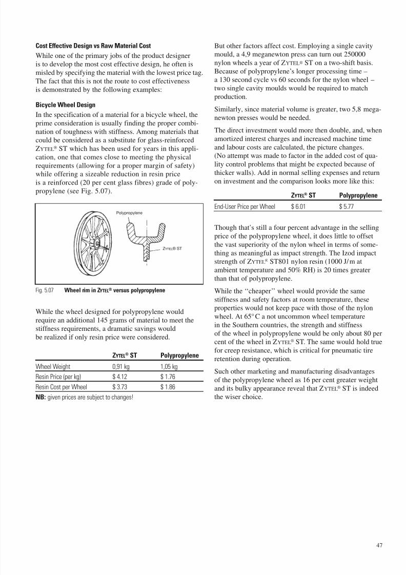
7/23/2019 f1236720 DuPont Engineering Polymers General Design Principles Module I
http://slidepdf.com/reader/full/f1236720-dupont-engineering-polymers-general-design-principles-module-i 49/155
47
Cost Effective Design vs Raw Material Cost
While one of the primary jobs of the product designeris to develop the most cost effective design, he often is
misled by specifying the material with the lowest price tag.
The fact that this is not the route to cost effectiveness
is demonstrated by the following examples:
Bicycle Wheel Design
In the specification of a material for a bicycle wheel, the
prime consideration is usually finding the proper combi-
nation of toughness with stiffness. Among materials thatcould be considered as a substitute for glass-reinforced
ZYTEL® ST which has been used for years in this appli-
cation, one that comes close to meeting the physical
requirements (allowing for a proper margin of safety)while offering a sizeable reduction in resin price
is a reinforced (20 per cent glass fibres) grade of poly-
propylene (see Fig. 5.07).
While the wheel designed for polypropylene would
require an additional 145 grams of material to meet thestiffness requirements, a dramatic savings would
be realized if only resin price were considered.
ZYTEL® ST Polypropylene
Wheel Weight 0,91 kg 1,05 kg
Resin Price (per kg) $ 4.12 $ 1.76
Resin Cost per Wheel $ 3.73 $ 1.86
NB: given prices are subject to changes!
But other factors affect cost. Employing a single cavitymould, a 4,9 meganewton press can turn out 250000
nylon wheels a year of ZYTEL® ST on a two-shift basis.
Because of polypropylene’s longer processing time – a 130 second cycle vs 60 seconds for the nylon wheel –
two single cavity moulds would be required to match
production.
Similarly, since material volume is greater, two 5,8 mega-
newton presses would be needed.
The direct investment would more then double, and, when
amortized interest charges and increased machine time
and labour costs are calculated, the picture changes.(No attempt was made to factor in the added cost of qua-
lity control problems that might be expected because of
thicker walls). Add in normal selling expenses and return
on investment and the comparison looks more like this:
ZYTEL® ST Polypropylene
End-User Price per Wheel $ 6.01 $ 5.77
Though that’s still a four percent advantage in the selling
price of the polypropylene wheel, it does little to offset
the vast superiority of the nylon wheel in terms of some-
thing as meaningful as impact strength. The Izod impactstrength of ZYTEL® ST801 nylon resin (1000 J/m at
ambient temperature and 50% RH) is 20 times greater
than that of polypropylene.
While the ‘‘cheaper’’ wheel would provide the same
stiffness and safety factors at room temperature, theseproperties would not keep pace with those of the nylon
wheel. At 65°C a not uncommon wheel temperature
in the Southern countries, the strength and stiffness
of the wheel in polypropylene would be only about 80 percent of the wheel in ZYTEL® ST. The same would hold true
for creep resistance, which is critical for pneumatic tire
retention during operation.
Such other marketing and manufacturing disadvantages
of the polypropylene wheel as 16 per cent greater weight
and its bulky appearance reveal that ZYTEL® ST is indeedthe wiser choice.
Polypropylene
ZYTEL® ST
Fig. 5.07 Wheel rim in ZYTEL® versus polypropylene

7/23/2019 f1236720 DuPont Engineering Polymers General Design Principles Module I
http://slidepdf.com/reader/full/f1236720-dupont-engineering-polymers-general-design-principles-module-i 50/155
48
Chair Seats Reevaluated
The same kind of study was conducted on a product that
is already being mass produced in a ‘‘cheaper’’ plastic,
the typical lightweight chair found in waiting rooms andinstitutions. An impact-modified, glass-reinforced nylon
at $ 3.95 per kg was substituted for unreinforced
polypropylene selling at $ 1.08 per kg. A chair seat wasdesigned in each material, using a rib reinforcement pat-tern that provided equal factors of safety and stiffness
with a minimum volume of material (see Fig. 5.08).
Again, using the same typical cost factors for annual pro-
duction of 250000 units, the results were not surprising.
ZYTEL®
73G30L Polypropylene
Seat Weight 1,27 kg 2,29 kg
Resin Cost $ 5.01 $ 2.47
End-User Price per Seat $ 7.21 $ 6.72
NB: given prices are subject to changes!
The end user price includes an additional $ 0.36 cost perpart occasioned by the longer cycle time (100 seconds vs
35 seconds for the glass reinforced ZYTEL® seat) required
for polypropylene – reducing what, at first, seemed likea 19 per cent price advantage to a 13 per cent advantage.
That advantage can be more than offset, however, by the
elimination of moulded-in metal inserts for leg and arm
attachment and shipping cost benefits of a seat thatweighs 44 per cent less.
Even more significant, the glass reinforced ZYTEL® seat
would exhibit much higher creep resistance, particularly
where chairs are stacked in high temperatures storageareas. It also offers much better impact resistance, a criti-cal consideration in institutional usage.
Wheelbarrow Frame – a Potential Design
While some barrow makers already produce a product
that takes advantage of the light weight and rust and
corrosion resistance of high density polyethylene orpolypropylene in the box, none – to the best of our
knowledge – have built a frame in plastic. This analysis
supplies a possible reason why: In a lower cost plastic,it would be both too heavy and too expensive!
Based on equivalent stiffness and safety factors, appropri-
ate cross sections were determined in frames (see Fig. 5.09)of RYNITE® 530 engineering thermoplastic polyester, a PET
(polyethylene terephthalate) resin reinforced with 30 per
cent glass fibres, and of polypropylene resin, also reinforced
with 30 per cent glass fibres.
Here are the results:
RYNITE® 530 Polypropylene
Frame Weight 8,16 kg 16,78 kg
Resin Price (per kg) $ 3.24 $ 1.83
Resin Cost $ 26.46 $ 30.71
End-User Price (per Frame) $ 36.86 $ 43.61
NB: given prices are subject to changes!
Again, volume and cycle time (65 seconds for RYNITE®
thermoplastic polyester vs. 120 seconds for polypropylene)
necessitates use of two moulds and two larger machinesfor processing 250000 polypropylene frames a year.
And as before, the product in the cheaper material suffers
in a comparison of such properties as strength, stiffness
and impact resistance at temperature extremes. Theexpensive materials is the most cost effective.
The bicycle wheel, seat and wheelbarrow frame examplesclearly show that a truly cost effective design analysis
must include performance, manufacturing and marketing
considerations and that the more expensive material isoften the most cost effective, particularly where the enditem is under stress.
3,3 mm
ZYTEL® 73G30L
46,6 mm
Polypropylene
42 mm5,1 mm
24,4 mm
10,2 mm
1,7 mm
22,1 mm
Fig. 5.08 Chair seat in glass fibre reinforced ZYTEL® versus
polypropylene
Fig. 5.09 Wheelbarrow frame in RYNITE® versus polypropylene
7,6 mm
Polypropylene
RYNITE® 530
18,7 mm
Polypropylene RYNITE® 530
35,6 mm
43,2 mm
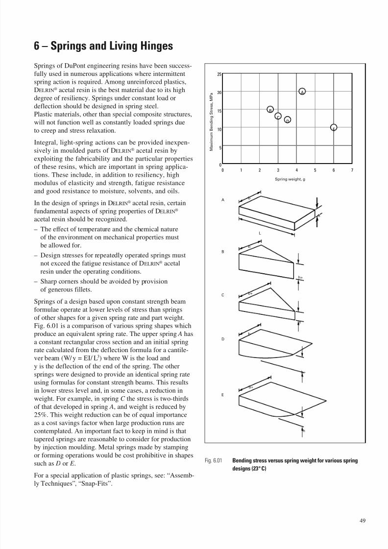
7/23/2019 f1236720 DuPont Engineering Polymers General Design Principles Module I
http://slidepdf.com/reader/full/f1236720-dupont-engineering-polymers-general-design-principles-module-i 51/155
6 – Springs and Living Hinges
Springs of DuPont engineering resins have been success-
fully used in numerous applications where intermittent
spring action is required. Among unreinforced plastics,
DELRIN® acetal resin is the best material due to its high
degree of resiliency. Springs under constant load ordeflection should be designed in spring steel.
Plastic materials, other than special composite structures,
will not function well as constantly loaded springs due
to creep and stress relaxation.
Integral, light-spring actions can be provided inexpen-
sively in moulded parts of DELRIN® acetal resin by
exploiting the fabricability and the particular properties
of these resins, which are important in spring applica-
tions. These include, in addition to resiliency, high
modulus of elasticity and strength, fatigue resistance
and good resistance to moisture, solvents, and oils.
In the design of springs in DELRIN® acetal resin, certain
fundamental aspects of spring properties of DELRIN®
acetal resin should be recognized.
– The effect of temperature and the chemical nature
of the environment on mechanical properties must
be allowed for.
– Design stresses for repeatedly operated springs must
not exceed the fatigue resistance of DELRIN® acetal
resin under the operating conditions.
– Sharp corners should be avoided by provision
of generous fillets.
Springs of a design based upon constant strength beam
formulae operate at lower levels of stress than springs
of other shapes for a given spring rate and part weight.
Fig. 6.01 is a comparison of various spring shapes which
produce an equivalent spring rate. The upper spring A has
a constant rectangular cross section and an initial springrate calculated from the deflection formula for a cantile-
ver beam (W/ y = EI/ L3) where W is the load and
y is the deflection of the end of the spring. The other
springs were designed to provide an identical spring rate
using formulas for constant strength beams. This resultsin lower stress level and, in some cases, a reduction in
weight. For example, in spring C the stress is two-thirds
of that developed in spring A, and weight is reduced by25%. This weight reduction can be of equal importance
as a cost savings factor when large production runs are
contemplated. An important fact to keep in mind is that
tapered springs are reasonable to consider for productionby injection moulding. Metal springs made by stamping
or forming operations would be cost prohibitive in shapes
such as D or E .
For a special application of plastic springs, see: “Assemb-
ly Techniques”, “Snap-Fits”.
Fig. 6.01 Bending stress versus spring weight for various spring
designs (23°C)
49
A
B
100
5
10
15
20
25
32 54 76
CD
E
M a x i m u m B
e n d i n g S t r e s s ,
M P
a
Spring weight, g
b
h
b
h+
b+
h
b
A
B
C
D
E
h+
b+
h
L

7/23/2019 f1236720 DuPont Engineering Polymers General Design Principles Module I
http://slidepdf.com/reader/full/f1236720-dupont-engineering-polymers-general-design-principles-module-i 52/155
50
Design of Living Hinges
In case of 180° bending: R =
L
Strain in extreme fibre : = b
2 L
Stress in extreme fibre : = b E
2 L (1 – 2)
For elastic behaviour, the following should be satisfied:
b<
2 e (1 2) (1)
L E
For other closing angles than 180°, adjust in the above
equation.
Living hinges, designed for elastic behaviour will have
rather big dimensions, which may make them less practi-
cal.
A certain amount of plasticity can be allowed before failure
occurs, which modifies equation (1) to:
b < 2
y ( 1 – 2) =2
y (1 – 2) (2)L E
L
R
= Poissons ratio
E = modulus of elasticityy = yield strength
e = elastic strength
Fig. 6.02 Recommended shape of living hinge
b l = b/2
b
l
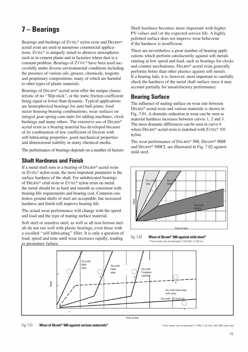
7/23/2019 f1236720 DuPont Engineering Polymers General Design Principles Module I
http://slidepdf.com/reader/full/f1236720-dupont-engineering-polymers-general-design-principles-module-i 53/155
7 – Bearings
Bearings and bushings of ZYTEL® nylon resin and DELRIN®
acetal resin are used in numerous commercial applica-tions. ZYTEL® is uniquely suited to abrasive atmospheres
such as in cement plants and in factories where dust is a
constant problem. Bearings of ZYTEL® have been used suc-cessfully under diverse environmental conditions includingthe presence of various oils, greases, chemicals, reagents
and proprietary compositions, many of which are harmful
to other types of plastic materials.
Bearings of DELRIN® acetal resin offer the unique charac-
teristic of no ‘‘Slip-stick ’’, or the static friction coefficientbeing equal or lower than dynamic. Typical applications
are hemispherical bearings for auto ball-joints; food
mixer housing-bearing combinations; wear surfaces on
integral gear-spring-cam units for adding machines; clock
bushings and many others. The extensive use of DELRIN®
acetal resin as a bearing material has developed because
of its combination of low coefficient of friction with
self-lubricating properties, good mechanical propertiesand dimensional stability in many chemical media.
The performance of bearings depends on a number of factors:
Shaft Hardness and FinishIf a metal shaft runs in a bearing of DELRIN® acetal resinor ZYTEL® nylon resin, the most important parameter is the
surface hardness of the shaft. For unlubricated bearings
of DELRIN®
cetal resin or ZYTEL®
nylon resin on metal,the metal should be as hard and smooth as consistent withbearing-life requirements and bearing cost. Common cen-
treless ground shafts of steel are acceptable, but increased
hardness and finish will improve bearing life.
The actual wear performance will change with the speed
and load and the type of mating surface material.
Soft steel or stainless steel, as well as all non-ferrous met-als do not run well with plastic bearings, even those with
a socalled ‘‘self-lubricating’’ filler. It is only a question of
load, speed and time until wear increases rapidly, leading
to premature failure.
Shaft hardness becomes more important with higherPV-values and / or the expected service life. A highly
polished surface does not improve wear behaviour
if the hardness is insufficient.
There are nevertheless a great number of bearing appli-cations which perform satisfactorily against soft metals
running at low speed and load, such as bearings for clocksand counter mechanisms. DELRIN® acetal resin generally
performs better than other plastics against soft metals.If a bearing fails, it is, however, most important to carefully
check the hardness of the metal shaft surface since it may
account partially for unsatisfactory performance.
Bearing SurfaceThe influence of mating surface on wear rate between
DELRIN® acetal resin and various materials is shown in
Fig. 7.01. A dramatic reduction in wear can be seen as
material hardness increases between curves 1, 2 and 3.
The most dramatic differences can be seen in curve 4where DELRIN® acetal resin is matched with ZYTEL® 101
nylon.
The wear performance of DELRIN® 500, DELRIN® 900F
and DELRIN® 500CL are illustrated in Fig. 7.02 againstmild steel.
51
DELRIN®
Mild
steelDELRIN®
Hard
steel
DELRIN®
Tungsten
carbide
DELRIN® Hard steel
with slots
DELRIN® – ZYTEL® 101
1 2 3
4
5
1
Time of test
W e a r
DELRIN®
500
DELRIN®
900F
W e a r
DELRIN®
500CL
Time of test
Fig. 7.02 Wear of DELRIN® 500 against mild steel** Thrust washer test; non-lubricated; P, 0,04 MPa; V, 0,95 m/s
Fig. 7.01 Wear of DELRIN® 500 against various materials* *Thrust washer test non-lubricated; P, 2 MPa; V, 50 mm/s; AISI 1080 carbon steel.
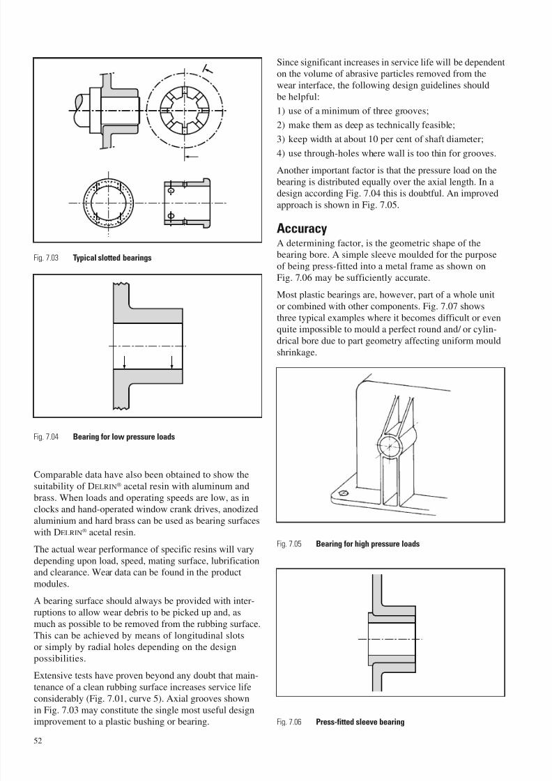
7/23/2019 f1236720 DuPont Engineering Polymers General Design Principles Module I
http://slidepdf.com/reader/full/f1236720-dupont-engineering-polymers-general-design-principles-module-i 54/155
Comparable data have also been obtained to show the
suitability of DELRIN® acetal resin with aluminum and
brass. When loads and operating speeds are low, as inclocks and hand-operated window crank drives, anodized
aluminium and hard brass can be used as bearing surfaces
with DELRIN® acetal resin.
The actual wear performance of specific resins will varydepending upon load, speed, mating surface, lubrificationand clearance. Wear data can be found in the product
modules.
A bearing surface should always be provided with inter-
ruptions to allow wear debris to be picked up and, as
much as possible to be removed from the rubbing surface.
This can be achieved by means of longitudinal slotsor simply by radial holes depending on the design
possibilities.
Extensive tests have proven beyond any doubt that main-
tenance of a clean rubbing surface increases service lifeconsiderably (Fig. 7.01, curve 5). Axial grooves shown
in Fig. 7.03 may constitute the single most useful designimprovement to a plastic bushing or bearing.
Since significant increases in service life will be dependenton the volume of abrasive particles removed from the
wear interface, the following design guidelines should
be helpful:
1) use of a minimum of three grooves;
2) make them as deep as technically feasible;
3) keep width at about 10 per cent of shaft diameter;
4) use through-holes where wall is too thin for grooves.
Another important factor is that the pressure load on the
bearing is distributed equally over the axial length. In adesign according Fig. 7.04 this is doubtful. An improved
approach is shown in Fig. 7.05.
AccuracyA determining factor, is the geometric shape of thebearing bore. A simple sleeve moulded for the purpose
of being press-fitted into a metal frame as shown on
Fig. 7.06 may be sufficiently accurate.
Most plastic bearings are, however, part of a whole unit
or combined with other components. Fig. 7.07 shows
three typical examples where it becomes difficult or evenquite impossible to mould a perfect round and/ or cylin-
drical bore due to part geometry affecting uniform mould
shrinkage.
52
Fig. 7.06 Press-fitted sleeve bearing
Fig. 7.05 Bearing for high pressure loads
Fig. 7.03 Typical slotted bearings
Fig. 7.04 Bearing for low pressure loads
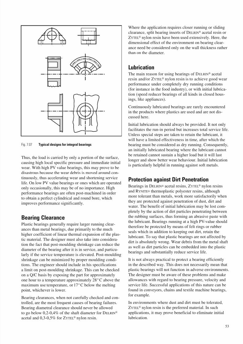
7/23/2019 f1236720 DuPont Engineering Polymers General Design Principles Module I
http://slidepdf.com/reader/full/f1236720-dupont-engineering-polymers-general-design-principles-module-i 55/155
Fig. 7.07 Typical designs for integral bearings
Thus, the load is carried by only a portion of the surface,
causing high local specific pressure and immediate initialwear. With high PV value bearings, this may prove to be
disastrous because the wear debris is moved around con-
tinuously, thus accelerating wear and shortening service
life. On low PV value bearings or ones which are operatedonly occasionally, this may be of no importance. High
performance bearings are often post-machined in order
to obtain a perfect cylindrical and round bore, which
improves performance significantly.
Bearing ClearancePlastic bearings generally require larger running clear-
ances than metal bearings, due primarily to the much
higher coefficient of linear thermal expansion of the plas-
tic material. The designer must also take into considera-tion the fact that post-moulding shrinkage can reduce the
diameter of the bearing after it is in service, and particu-
larly if the service temperature is elevated. Post-moulding
shrinkage can be minimized by proper moulding condi-tions. The engineer should include in his specifications
a limit on post-moulding shrinkage. This can be checked
on a Q/C basis by exposing the part for approximately
one hour to a temperature approximately 28°C above themaximum use temperature, or 17°C below the melting
point, whichever is lower.
Bearing clearances, when not carefully checked and con-
trolled, are the most frequent causes of bearing failures.Bearing diametral clearance should never be allowed
to go below 0,2-0,4% of the shaft diameter for DELRIN®
acetal and 0,3-0,5% for ZYTEL® nylon resin.
Where the application requires closer running or slidingclearance, split bearing inserts of DELRIN® acetal resin or
ZYTEL® nylon resin have been used extensively. Here, the
dimensional effect of the environment on bearing clear-
ance need be considered only on the wall thickness ratherthan on the diameter.
LubricationThe main reason for using bearings of DELRIN® acetalresin and/or ZYTEL® nylon resin is to achieve good wear
performance under completely dry running conditions
(for instance in the food industry), or with initial lubrica-
tion (speed reducer bearings of all kinds in closed hous-ings, like appliances).
Continuously lubricated bearings are rarely encounteredin the products where plastics are used and are not dis-
cussed here.
Initial lubrication should always be provided. It not only
facilitates the run-in period but increases total service life.
Unless special steps are taken to retain the lubricant, it
will have a limited effectiveness in time, after which thebearing must be considered as dry running. Consequently,
an initially lubricated bearing where the lubricant cannot
be retained cannot sustain a higher load but it will last
longer and show better wear behaviour. Initial lubricationis particularly helpful in running against soft metals.
Protection against Dirt PenetrationBearings in DELRIN® acetal resins, ZYTEL® nylon resins
and RYNITE® thermoplastic polyester resins, althoughmore tolerant than metals, work more satisfactorily when
they are protected against penetration of dust, dirt and
water. The benefit of initial lubrication may be lost com-
pletely by the action of dirt particles penetrating betweenthe rubbing surfaces, thus forming an abrasive paste with
the lubricant. Bearings running at a high PV-value should
therefore be protected by means of felt rings or rubber
seals which in addition to keeping out dirt, retain thelubricant. To say that plastic bearings are not affected by
dirt is absolutely wrong. Wear debris from the metal shaftas well as dirt particles can be embedded into the plastic
bearings and substantially reduce service life.
It is not always practical to protect a bearing efficiently
in the described way. This does not necessarily mean thatplastic bearings will not function in adverse environments.
The designer must be aware of these problems and make
allowances with regard to bearing pressure, velocity and
service life. Successful applications of this nature can befound in conveyors, chains and textile machine bearings,
for example.
In environments where dust and dirt must be tolerated,ZYTEL® nylon resin is the preferred material. In such
applications, it may prove beneficial to eliminate initial
lubrication.
53
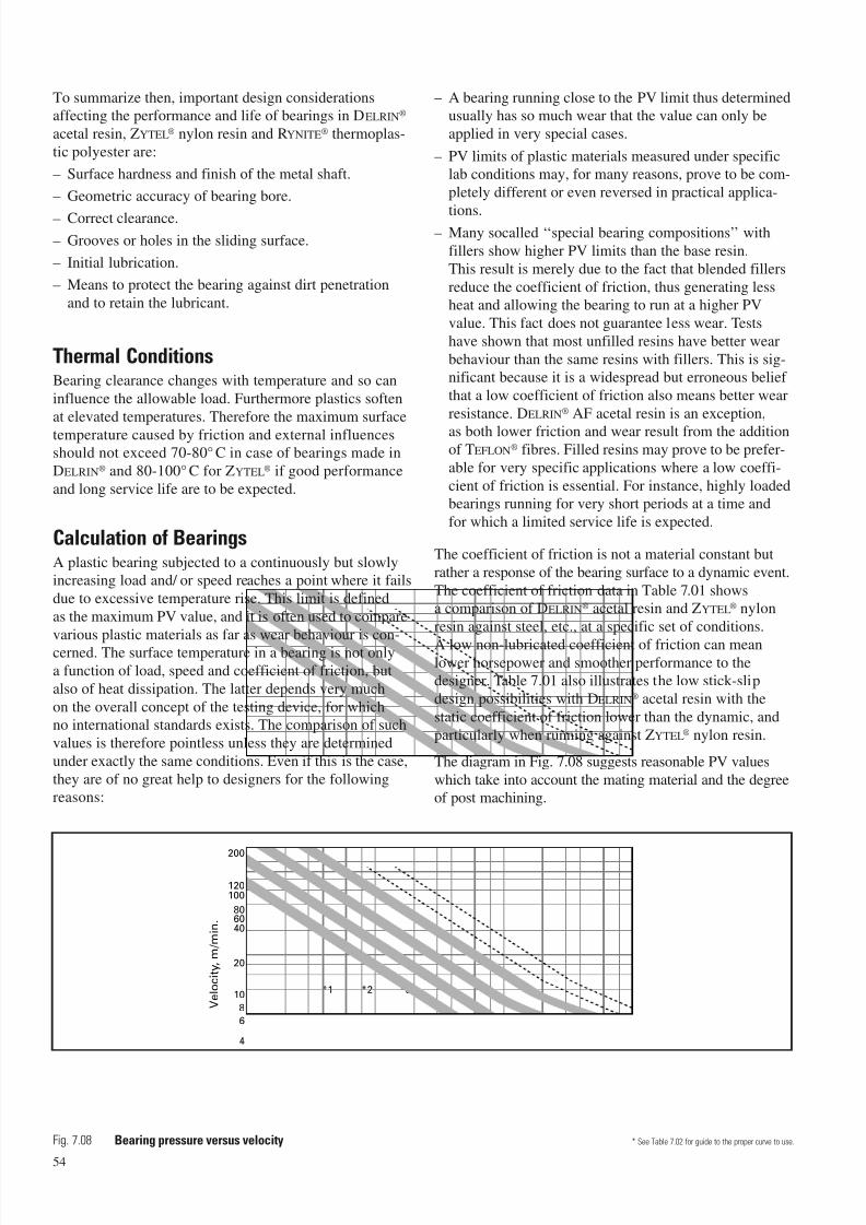
7/23/2019 f1236720 DuPont Engineering Polymers General Design Principles Module I
http://slidepdf.com/reader/full/f1236720-dupont-engineering-polymers-general-design-principles-module-i 56/155
To summarize then, important design considerationsaffecting the performance and life of bearings in DELRIN®
acetal resin, ZYTEL® nylon resin and RYNITE® thermoplas-
tic polyester are:
– Surface hardness and finish of the metal shaft.
– Geometric accuracy of bearing bore.
– Correct clearance.
– Grooves or holes in the sliding surface.
– Initial lubrication.
– Means to protect the bearing against dirt penetration
and to retain the lubricant.
Thermal ConditionsBearing clearance changes with temperature and so can
influence the allowable load. Furthermore plastics soften
at elevated temperatures. Therefore the maximum surface
temperature caused by friction and external influencesshould not exceed 70-80° C in case of bearings made in
DELRIN® and 80-100° C for ZYTEL® if good performance
and long service life are to be expected.
Calculation of BearingsA plastic bearing subjected to a continuously but slowlyincreasing load and/ or speed reaches a point where it fails
due to excessive temperature rise. This limit is defined
as the maximum PV value, and it is often used to compare
various plastic materials as far as wear behaviour is con-cerned. The surface temperature in a bearing is not only
a function of load, speed and coefficient of friction, but
also of heat dissipation. The latter depends very much
on the overall concept of the testing device, for whichno international standards exists. The comparison of such
values is therefore pointless unless they are determined
under exactly the same conditions. Even if this is the case,
they are of no great help to designers for the followingreasons:
– A bearing running close to the PV limit thus determinedusually has so much wear that the value can only be
applied in very special cases.
– PV limits of plastic materials measured under specificlab conditions may, for many reasons, prove to be com-
pletely different or even reversed in practical applica-
tions.– Many socalled ‘‘special bearing compositions’’ with
fillers show higher PV limits than the base resin.
This result is merely due to the fact that blended fillers
reduce the coefficient of friction, thus generating lessheat and allowing the bearing to run at a higher PV
value. This fact does not guarantee less wear. Tests
have shown that most unfilled resins have better wear
behaviour than the same resins with fillers. This is sig-nificant because it is a widespread but erroneous belief
that a low coefficient of friction also means better wear
resistance. DELRIN® AF acetal resin is an exception,
as both lower friction and wear result from the additionof TEFLON® fibres. Filled resins may prove to be prefer-
able for very specific applications where a low coeffi-
cient of friction is essential. For instance, highly loadedbearings running for very short periods at a time and
for which a limited service life is expected.
The coefficient of friction is not a material constant but
rather a response of the bearing surface to a dynamic event.
The coefficient of friction data in Table 7.01 showsa comparison of DELRIN® acetal resin and ZYTEL® nylon
resin against steel, etc., at a specific set of conditions.
A low non-lubricated coefficient of friction can meanlower horsepower and smoother performance to thedesigner. Table 7.01 also illustrates the low stick-slip
design possibilities with DELRIN® acetal resin with the
static coefficient of friction lower than the dynamic, and
particularly when running against ZYTEL® nylon resin.
The diagram in Fig. 7.08 suggests reasonable PV values
which take into account the mating material and the degreeof post machining.
54
0,01 1010,12
4
6
8
10 *1 *2 *3 *4 *5
*6
20
200
406080
100120
Bearing pressure, MPa
V e l o c i t y , m / m i n .
Fig. 7.08 Bearing pressure versus velocity * See Table 7.02 for guide to the proper curve to use.
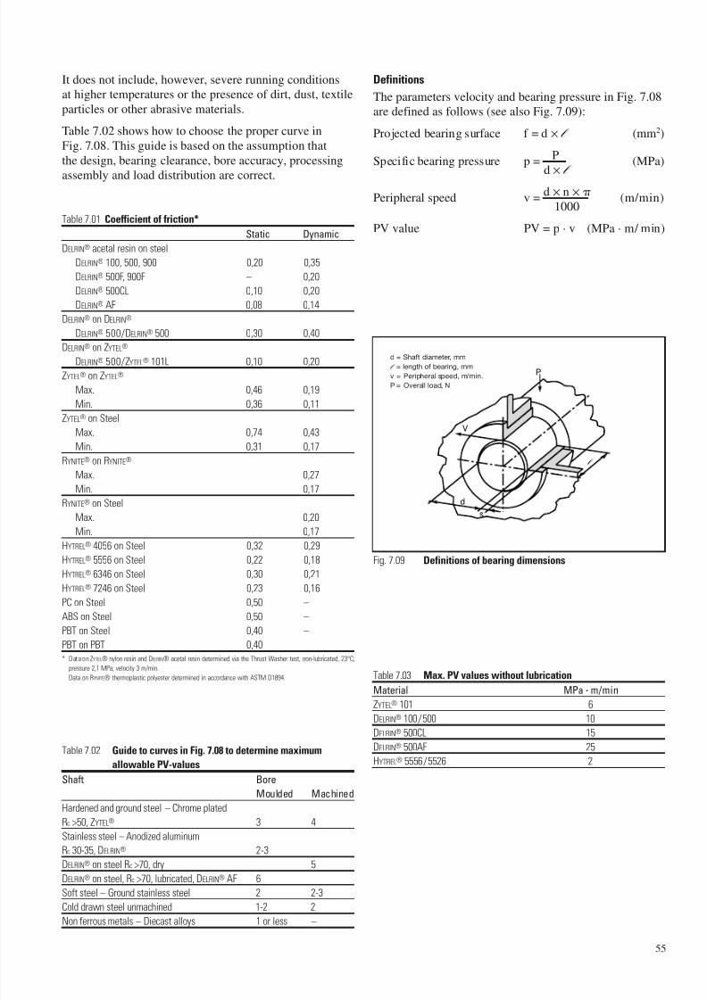
7/23/2019 f1236720 DuPont Engineering Polymers General Design Principles Module I
http://slidepdf.com/reader/full/f1236720-dupont-engineering-polymers-general-design-principles-module-i 57/155
55
It does not include, however, severe running conditionsat higher temperatures or the presence of dirt, dust, textile
particles or other abrasive materials.
Table 7.02 shows how to choose the proper curve in
Fig. 7.08. This guide is based on the assumption that
the design, bearing clearance, bore accuracy, processing
assembly and load distribution are correct.
Table 7.01 Coefficient of friction*
Static Dynamic
DELRIN® acetal resin on steel
DELRIN® 100, 500, 900 0,20 0,35
DELRIN® 500F, 900F – 0,20
DELRIN® 500CL 0,10 0,20
DELRIN® AF 0,08 0,14
DELRIN® on DELRIN®
DELRIN® 500/DELRIN® 500 0,30 0,40
DELRIN®
on ZYTEL®
DELRIN® 500/ZYTEL® 101L 0,10 0,20
ZYTEL® on ZYTEL®
Max. 0,46 0,19
Min. 0,36 0,11
ZYTEL® on Steel
Max. 0,74 0,43
Min. 0,31 0,17
RYNITE® on RYNITE®
Max. 0,27
Min. 0,17
RYNITE® on Steel
Max. 0,20
Min. 0,17
HYTREL® 4056 on Steel 0,32 0,29
HYTREL® 5556 on Steel 0,22 0,18
HYTREL® 6346 on Steel 0,30 0,21
HYTREL® 7246 on Steel 0,23 0,16
PC on Steel 0,50 –
ABS on Steel 0,50 –
PBT on Steel 0,40 –
PBT on PBT 0,40
* Data on ZYTEL® nylon resin and DELRIN® acetal resin determined via the Thrust Washer test, non-lubricated, 23°C;
pressure 2,1 MPa; velocity 3 m/min.
Data on RYNITE® thermoplastic polyester determined in accordance with ASTM D1894.
Table 7.02 Guide to curves in Fig. 7.08 to determine maximum
allowable PV-values
Shaft Bore
Moulded Machined
Hardened and ground steel – Chrome plated
Rc >50, ZYTEL® 3 4
Stainless steel – Anodized aluminum
Rc 30-35, DELRIN® 2-3
DELRIN® on steel Rc >70, dry 5
DELRIN® on steel, Rc >70, lubricated, DELRIN® AF 6Soft steel – Ground stainless steel 2 2-3
Cold drawn steel unmachined 1-2 2
Non ferrous metals – Diecast alloys 1 or less –
Definitions
The parameters velocity and bearing pressure in Fig. 7.08are defined as follows (see also Fig. 7.09):
Projected bearing surface f = d × l (mm2)
Specific bearing pressure p =P
(MPa)
d× l
Peripheral speed v =d × n ×
(m/min)1000
PV value PV = p · v (MPa · m/ min)
Table 7.03 Max. PV values without lubrication
Material MPa · m/min
ZYTEL® 101 6
DELRIN® 100/500 10
DELRIN® 500CL 15
DELRIN® 500AF 25
HYTREL® 5556/5526 2
P
V
d
s
l
d = Shaft diameter, mm
l = length of bearing, mm
v = Peripheral speed, m/min.
P = Overall load, N
Fig. 7.09 Definitions of bearing dimensions
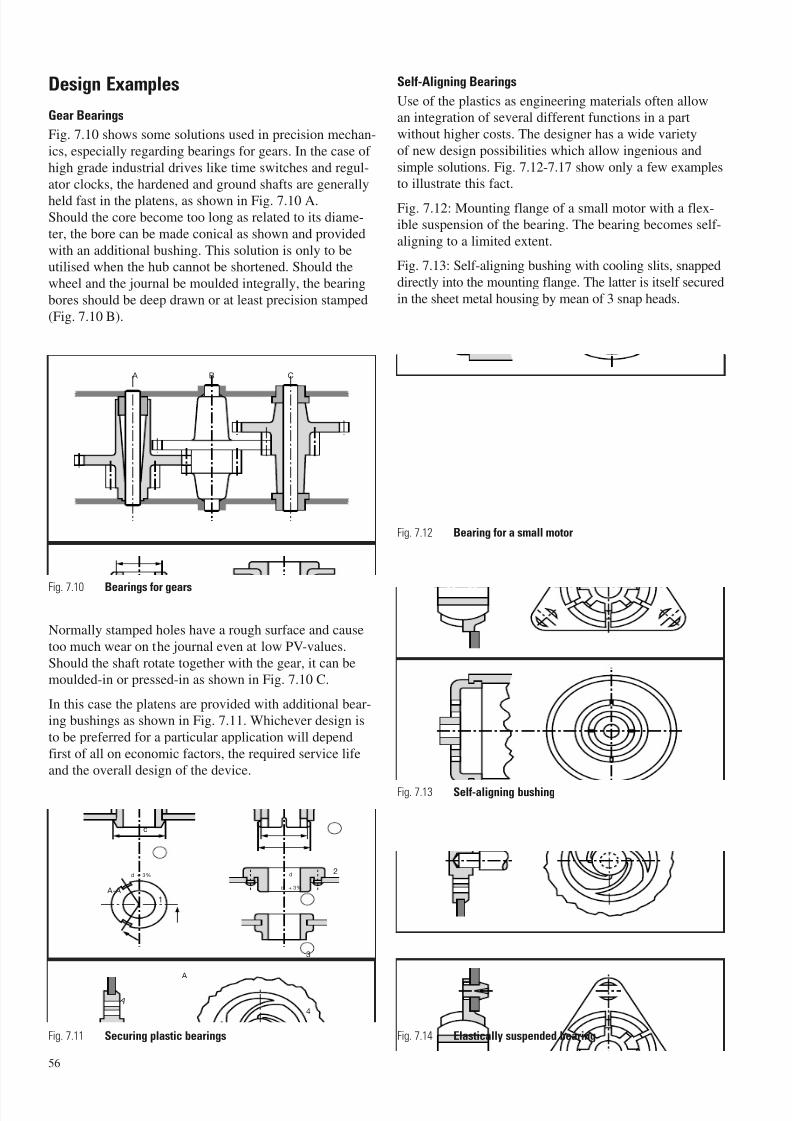
7/23/2019 f1236720 DuPont Engineering Polymers General Design Principles Module I
http://slidepdf.com/reader/full/f1236720-dupont-engineering-polymers-general-design-principles-module-i 58/155
56
Fig. 7.14 Elastically suspended bearing
Design Examples
Gear Bearings
Fig. 7.10 shows some solutions used in precision mechan-
ics, especially regarding bearings for gears. In the case of
high grade industrial drives like time switches and regul-
ator clocks, the hardened and ground shafts are generally
held fast in the platens, as shown in Fig. 7.10 A.Should the core become too long as related to its diame-
ter, the bore can be made conical as shown and provided
with an additional bushing. This solution is only to beutilised when the hub cannot be shortened. Should the
wheel and the journal be moulded integrally, the bearing
bores should be deep drawn or at least precision stamped
(Fig. 7.10 B).
Normally stamped holes have a rough surface and cause
too much wear on the journal even at low PV-values.
Should the shaft rotate together with the gear, it can bemoulded-in or pressed-in as shown in Fig. 7.10 C.
In this case the platens are provided with additional bear-ing bushings as shown in Fig. 7.11. Whichever design is
to be preferred for a particular application will depend
first of all on economic factors, the required service life
and the overall design of the device.
Self-Aligning Bearings
Use of the plastics as engineering materials often allowan integration of several different functions in a part
without higher costs. The designer has a wide variety
of new design possibilities which allow ingenious and
simple solutions. Fig. 7.12-7.17 show only a few examplesto illustrate this fact.
Fig. 7.12: Mounting flange of a small motor with a flex-ible suspension of the bearing. The bearing becomes self-
aligning to a limited extent.
Fig. 7.13: Self-aligning bushing with cooling slits, snapped
directly into the mounting flange. The latter is itself secured
in the sheet metal housing by mean of 3 snap heads.
1
A B C
A-A
d + 3%
d + 3%
d
d
A
A
3
4
2
Fig. 7.10 Bearings for gears
Fig. 7.11 Securing plastic bearings
Fig. 7.12 Bearing for a small motor
Fig. 7.13 Self-aligning bushing
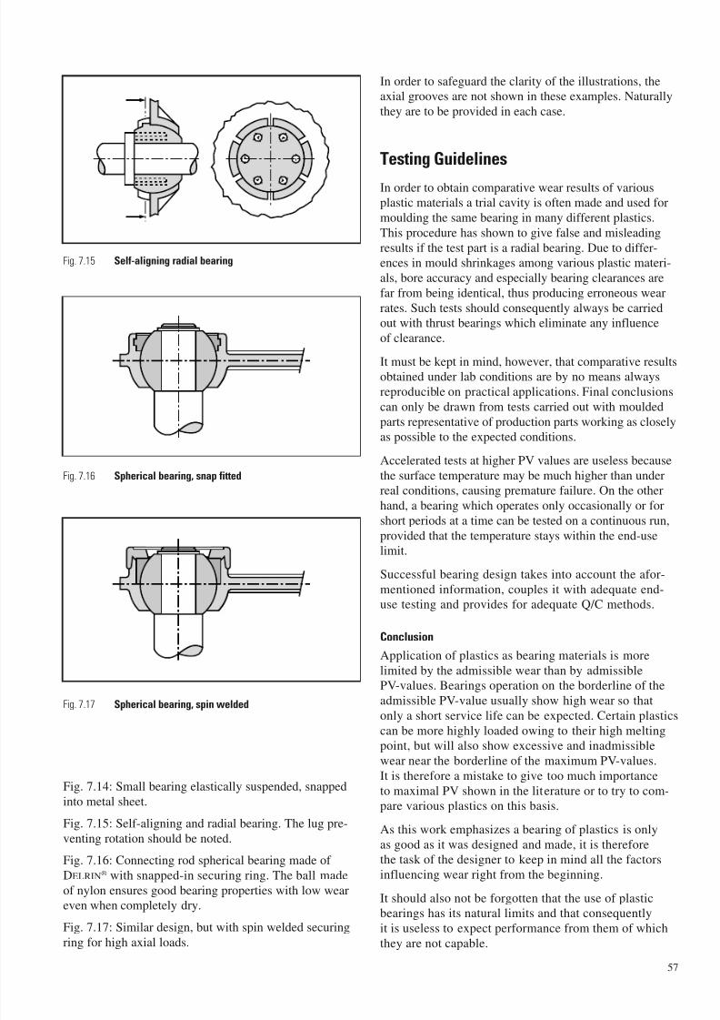
7/23/2019 f1236720 DuPont Engineering Polymers General Design Principles Module I
http://slidepdf.com/reader/full/f1236720-dupont-engineering-polymers-general-design-principles-module-i 59/155
Fig. 7.14: Small bearing elastically suspended, snapped
into metal sheet.
Fig. 7.15: Self-aligning and radial bearing. The lug pre-
venting rotation should be noted.
Fig. 7.16: Connecting rod spherical bearing made of
DELRIN® with snapped-in securing ring. The ball made
of nylon ensures good bearing properties with low weareven when completely dry.
Fig. 7.17: Similar design, but with spin welded securing
ring for high axial loads.
In order to safeguard the clarity of the illustrations, theaxial grooves are not shown in these examples. Naturally
they are to be provided in each case.
Testing Guidelines
In order to obtain comparative wear results of variousplastic materials a trial cavity is often made and used for
moulding the same bearing in many different plastics.
This procedure has shown to give false and misleading
results if the test part is a radial bearing. Due to differ-ences in mould shrinkages among various plastic materi-
als, bore accuracy and especially bearing clearances are
far from being identical, thus producing erroneous wear
rates. Such tests should consequently always be carriedout with thrust bearings which eliminate any influence
of clearance.
It must be kept in mind, however, that comparative resultsobtained under lab conditions are by no means always
reproducible on practical applications. Final conclusions
can only be drawn from tests carried out with moulded
parts representative of production parts working as closelyas possible to the expected conditions.
Accelerated tests at higher PV values are useless because
the surface temperature may be much higher than underreal conditions, causing premature failure. On the other
hand, a bearing which operates only occasionally or for
short periods at a time can be tested on a continuous run,
provided that the temperature stays within the end-uselimit.
Successful bearing design takes into account the afor-
mentioned information, couples it with adequate end-use testing and provides for adequate Q/C methods.
Conclusion
Application of plastics as bearing materials is more
limited by the admissible wear than by admissiblePV-values. Bearings operation on the borderline of the
admissible PV-value usually show high wear so that
only a short service life can be expected. Certain plasticscan be more highly loaded owing to their high meltingpoint, but will also show excessive and inadmissible
wear near the borderline of the maximum PV-values.
It is therefore a mistake to give too much importance
to maximal PV shown in the literature or to try to com-pare various plastics on this basis.
As this work emphasizes a bearing of plastics is only
as good as it was designed and made, it is thereforethe task of the designer to keep in mind all the factors
influencing wear right from the beginning.
It should also not be forgotten that the use of plasticbearings has its natural limits and that consequently
it is useless to expect performance from them of which
they are not capable.
57
Fig. 7.15 Self-aligning radial bearing
Fig. 7.16 Spherical bearing, snap fitted
Fig. 7.17 Spherical bearing, spin welded

7/23/2019 f1236720 DuPont Engineering Polymers General Design Principles Module I
http://slidepdf.com/reader/full/f1236720-dupont-engineering-polymers-general-design-principles-module-i 60/155
58
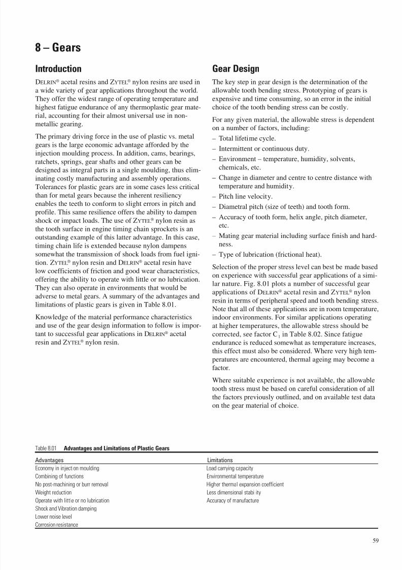
7/23/2019 f1236720 DuPont Engineering Polymers General Design Principles Module I
http://slidepdf.com/reader/full/f1236720-dupont-engineering-polymers-general-design-principles-module-i 61/155
59
8 – Gears
Introduction
DELRIN® acetal resins and ZYTEL® nylon resins are used in
a wide variety of gear applications throughout the world.
They offer the widest range of operating temperature andhighest fatigue endurance of any thermoplastic gear mate-
rial, accounting for their almost universal use in non-
metallic gearing.
The primary driving force in the use of plastic vs. metal
gears is the large economic advantage afforded by the
injection moulding process. In addition, cams, bearings,
ratchets, springs, gear shafts and other gears can be
designed as integral parts in a single moulding, thus elim-
inating costly manufacturing and assembly operations.
Tolerances for plastic gears are in some cases less critical
than for metal gears because the inherent resiliency
enables the teeth to conform to slight errors in pitch and
profile. This same resilience offers the ability to dampen
shock or impact loads. The use of ZYTEL® nylon resin as
the tooth surface in engine timing chain sprockets is an
outstanding example of this latter advantage. In this case,
timing chain life is extended because nylon dampens
somewhat the transmission of shock loads from fuel igni-
tion. ZYTEL® nylon resin and DELRIN® acetal resin have
low coefficients of friction and good wear characteristics,
offering the ability to operate with little or no lubrication.
They can also operate in environments that would be
adverse to metal gears. A summary of the advantages andlimitations of plastic gears is given in Table 8.01.
Knowledge of the material performance characteristics
and use of the gear design information to follow is impor-
tant to successful gear applications in DELRIN® acetal
resin and ZYTEL® nylon resin.
Gear Design
The key step in gear design is the determination of the
allowable tooth bending stress. Prototyping of gears is
expensive and time consuming, so an error in the initialchoice of the tooth bending stress can be costly.
For any given material, the allowable stress is dependenton a number of factors, including:
– Total lifetime cycle.
– Intermittent or continuous duty.
– Environment – temperature, humidity, solvents,
chemicals, etc.
– Change in diameter and centre to centre distance with
temperature and humidity.
– Pitch line velocity.– Diametral pitch (size of teeth) and tooth form.
– Accuracy of tooth form, helix angle, pitch diameter,etc.
– Mating gear material including surface finish and hard-ness.
– Type of lubrication (frictional heat).
Selection of the proper stress level can best be made based
on experience with successful gear applications of a simi-lar nature. Fig. 8.01 plots a number of successful gear
applications of DELRIN® acetal resin and ZYTEL® nylon
resin in terms of peripheral speed and tooth bending stress.Note that all of these applications are in room temperature,indoor environments. For similar applications operating
at higher temperatures, the allowable stress should be
corrected, see factor C1 in Table 8.02. Since fatigue
endurance is reduced somewhat as temperature increases,this effect must also be considered. Where very high tem-
peratures are encountered, thermal ageing may become a
factor.
Where suitable experience is not available, the allowable
tooth stress must be based on careful consideration of all
the factors previously outlined, and on available test dataon the gear material of choice.
Table 8.01 Advantages and Limitations of Plastic Gears
Advantages Limitations
Economy in injection moulding Load carrying capacity
Combining of functions Environmental temperature
No post-machining or burr removal Higher thermal expansion coefficient
Weight reduction Less dimensional stability
Operate with little or no lubrication Accuracy of manufactureShock and Vibration damping
Lower noise level
Corrosion resistance
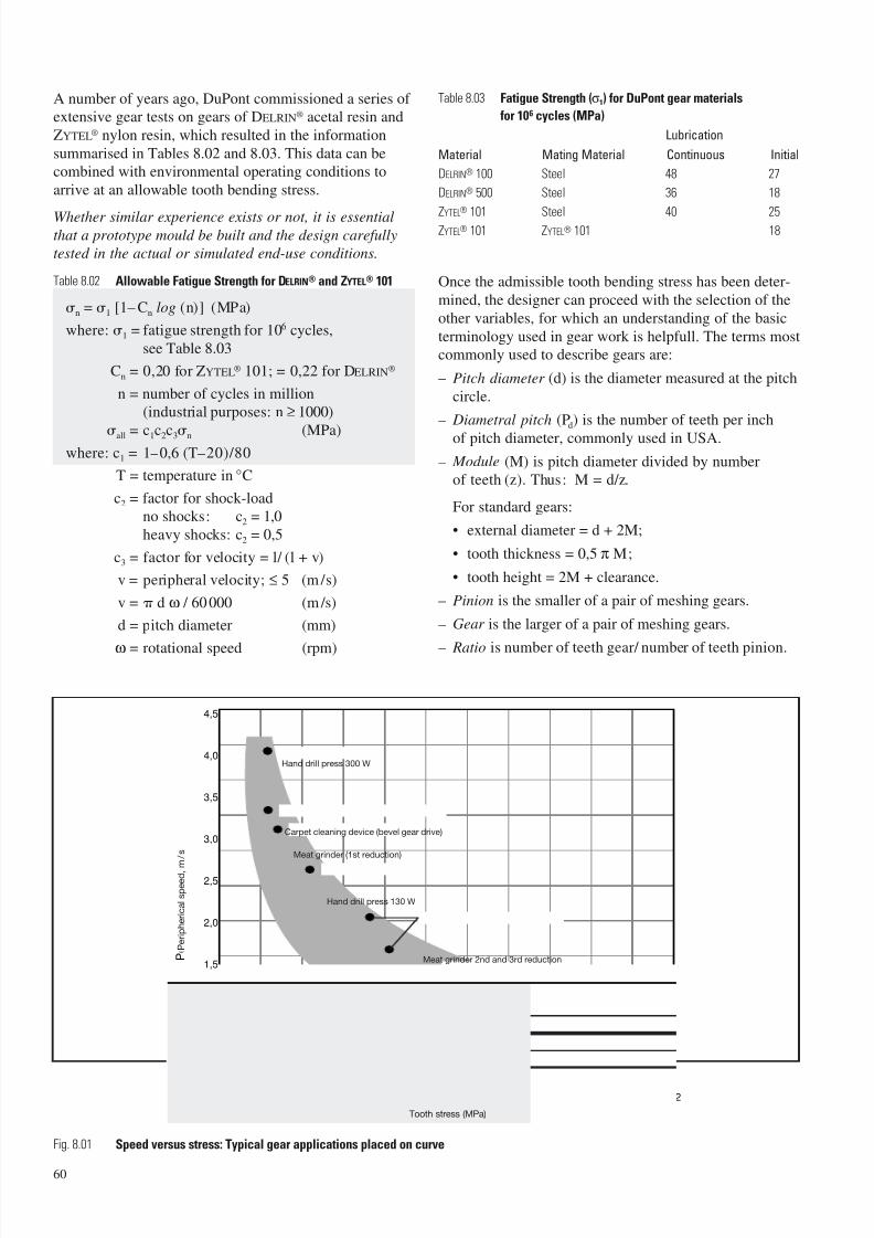
7/23/2019 f1236720 DuPont Engineering Polymers General Design Principles Module I
http://slidepdf.com/reader/full/f1236720-dupont-engineering-polymers-general-design-principles-module-i 62/155
Tooth stress (MPa)
P e r i p h e r i c a l s p e e d
, m / s
0 2 4 6 8 10 12 14 16 18 20 22
2,0
1,5
1,0
0,5
4,0
4,5
3,5
3,0
2,5
0
60
A number of years ago, DuPont commissioned a series of extensive gear tests on gears of DELRIN® acetal resin and
ZYTEL® nylon resin, which resulted in the information
summarised in Tables 8.02 and 8.03. This data can becombined with environmental operating conditions to
arrive at an allowable tooth bending stress.
Whether similar experience exists or not, it is essentialthat a prototype mould be built and the design carefully
tested in the actual or simulated end-use conditions.
Table 8.02 Allowable Fatigue Strength for DELRIN® and ZYTEL® 101
n = 1 [1– Cn log (n)] (MPa)
where: 1 = fatigue strength for 106 cycles,
see Table 8.03
Cn = 0,20 for ZYTEL® 101; = 0,22 for DELRIN®
n = number of cycles in million(industrial purposes: n ≥ 1000)
all = c1c2c3n (MPa)where: c1 = 1–0,6 (T–20)/80
T = temperature in °C
c2 = factor for shock-loadno shocks: c2 = 1,0
heavy shocks: c2 = 0,5
c3 = factor for velocity = l/ (l + v)
v = peripheral velocity; ≤ 5 (m /s)
v = d ω / 60000 (m /s)
d = pitch diameter (mm)
ω = rotational speed (rpm)
Table 8.03 Fatigue Strength (σ1) for DuPont gear materials
for 106 cycles (MPa)
Lubrication
Material Mating Material Continuous Initial
DELRIN® 100 Steel 48 27
DELRIN® 500 Steel 36 18
ZYTEL®
101 Steel 40 25ZYTEL® 101 ZYTEL® 101 18
Once the admissible tooth bending stress has been deter-
mined, the designer can proceed with the selection of the
other variables, for which an understanding of the basic
terminology used in gear work is helpfull. The terms mostcommonly used to describe gears are:
– Pitch diameter (d) is the diameter measured at the pitch
circle.
– Diametral pitch (Pd) is the number of teeth per inch
of pitch diameter, commonly used in USA.
– Module (M) is pitch diameter divided by numberof teeth (z). Thus: M = d/z.
For standard gears:
• external diameter = d + 2M;
• tooth thickness = 0,5 π M;
• tooth height = 2M + clearance.
– Pinion is the smaller of a pair of meshing gears.
– Gear is the larger of a pair of meshing gears.
– Ratio is number of teeth gear/ number of teeth pinion.
Hand drill press 300 W
Fig. 8.01 Speed versus stress: Typical gear applications placed on curve
Meat grinder 2nd and 3rd reduction
Planetary gear drive (Washing
machines and general
industrial purposes)
Planetary gear drive
Planetary gear drive
for washing machines
Hand drill press 130 W
Meat grinder (1st reduction)
Carpet cleaning device (bevel gear drive)
Tooth stress (MPa)
P e r i p h e r i c a l s p e e d , m
/ s
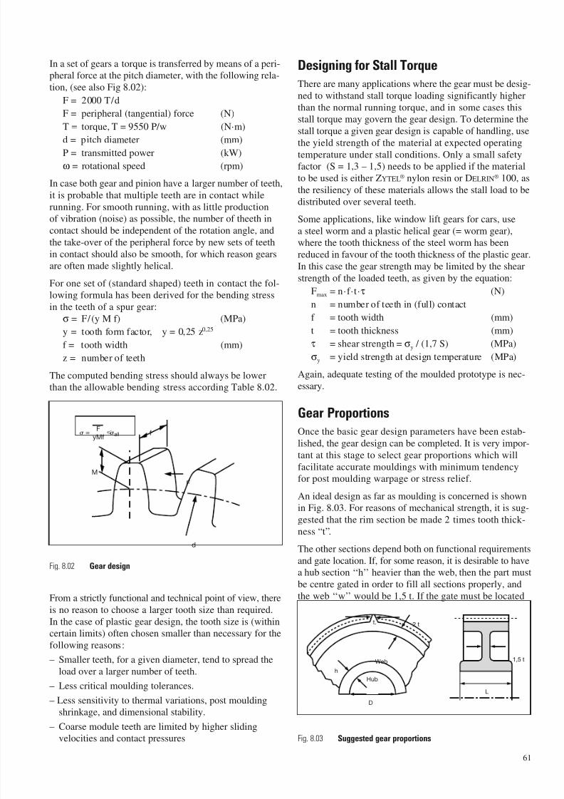
7/23/2019 f1236720 DuPont Engineering Polymers General Design Principles Module I
http://slidepdf.com/reader/full/f1236720-dupont-engineering-polymers-general-design-principles-module-i 63/155
In a set of gears a torque is transferred by means of a peri-
pheral force at the pitch diameter, with the following rela-
tion, (see also Fig 8.02):
F = 2000 T/d
F = peripheral (tangential) force (N)
T = torque, T = 9550 P/w (N·m)
d = pitch diameter (mm)P = transmitted power (kW)
ω = rotational speed (rpm)
In case both gear and pinion have a larger number of teeth,
it is probable that multiple teeth are in contact while
running. For smooth running, with as little productionof vibration (noise) as possible, the number of theeth in
contact should be independent of the rotation angle, and
the take-over of the peripheral force by new sets of teeth
in contact should also be smooth, for which reason gearsare often made slightly helical.
For one set of (standard shaped) teeth in contact the fol-lowing formula has been derived for the bending stress
in the teeth of a spur gear:
σ = F/(y M f) (MPa)
y = tooth form factor, y = 0,25 z0,25
f = tooth width (mm)
z = number of teeth
The computed bending stress should always be lowerthan the allowable bending stress according Table 8.02.
From a strictly functional and technical point of view, there
is no reason to choose a larger tooth size than required.
In the case of plastic gear design, the tooth size is (withincertain limits) often chosen smaller than necessary for the
following reasons:
– Smaller teeth, for a given diameter, tend to spread the
load over a larger number of teeth.
– Less critical moulding tolerances.
– Less sensitivity to thermal variations, post mouldingshrinkage, and dimensional stability.
– Coarse module teeth are limited by higher slidingvelocities and contact pressures
Designing for Stall Torque
There are many applications where the gear must be desig-
ned to withstand stall torque loading significantly higher
than the normal running torque, and in some cases thisstall torque may govern the gear design. To determine the
stall torque a given gear design is capable of handling, use
the yield strength of the material at expected operatingtemperature under stall conditions. Only a small safetyfactor (S = 1,3 – 1,5) needs to be applied if the material
to be used is either ZYTEL® nylon resin or DELRIN® 100, as
the resiliency of these materials allows the stall load to be
distributed over several teeth.
Some applications, like window lift gears for cars, use
a steel worm and a plastic helical gear (= worm gear),where the tooth thickness of the steel worm has been
reduced in favour of the tooth thickness of the plastic gear.
In this case the gear strength may be limited by the shear
strength of the loaded teeth, as given by the equation:Fmax = n·f ·t·τ (N)
n = number of teeth in (full) contact
f = tooth width (mm)
t = tooth thickness (mm)
τ = shear strength = σy / (1,7 S) (MPa)
σy = yield strength at design temperature (MPa)
Again, adequate testing of the moulded prototype is nec-
essary.
Gear ProportionsOnce the basic gear design parameters have been estab-
lished, the gear design can be completed. It is very impor-
tant at this stage to select gear proportions which will
facilitate accurate mouldings with minimum tendencyfor post moulding warpage or stress relief.
An ideal design as far as moulding is concerned is shownin Fig. 8.03. For reasons of mechanical strength, it is sug-
gested that the rim section be made 2 times tooth thick-
ness “t”.
The other sections depend both on functional requirements
and gate location. If, for some reason, it is desirable to havea hub section ‘‘h’’ heavier than the web, then the part must
be centre gated in order to fill all sections properly, and
the web ‘‘w’’ would be 1,5 t. If the gate must be located
61
=F
allyMf
Fig. 8.02 Gear design
D
Hub
h
Web
2 tt.
L
1,5 t
Fig. 8.03 Suggested gear proportions
M
f
F
d
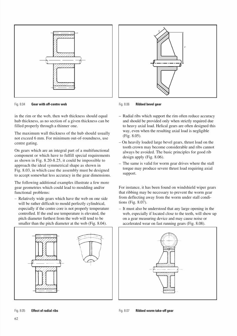
7/23/2019 f1236720 DuPont Engineering Polymers General Design Principles Module I
http://slidepdf.com/reader/full/f1236720-dupont-engineering-polymers-general-design-principles-module-i 64/155
in the rim or the web, then web thickness should equalhub thickness, as no section of a given thickness can befilled properly through a thinner one.
The maximum wall thickness of the hub should usuallynot exceed 6 mm. For minimum out-of-roundness, use
centre gating.
On gears which are an integral part of a multifunctional
component or which have to fulfill special requirements
as shown in Fig. 8.20-8.25, it could be impossible to
approach the ideal symmetrical shape as shown inFig. 8.03, in which case the assembly must be designed
to accept somewhat less accuracy in the gear dimensions.The following additional examples illustrate a few more
gear geometries which could lead to moulding and/or
functional problems:
– Relatively wide gears which have the web on one side
will be rather difficult to mould perfectly cylindrical,
especially if the centre core is not properly temperaturecontrolled. If the end use temperature is elevated, the
pitch diameter furthest from the web will tend to be
smaller than the pitch diameter at the web (Fig. 8.04).
– Radial ribs which support the rim often reduce accuracyand should be provided only when strictly required dueto heavy axial load. Helical gears are often designed this
way, even when the resulting axial load is negligible
(Fig. 8.05).
– On heavily loaded large bevel gears, thrust load on thetooth crown may become considerable and ribs cannot
always be avoided. The basic principles for good rib
design apply (Fig. 8.06).
– The same is valid for worm gear drives where the stall
torque may produce severe thrust load requiring axial
support.
For instance, it has been found on windshield wiper gears
that ribbing may be necessary to prevent the worm gear
from deflecting away from the worm under stall condi-tions (Fig. 8.07).
– It must also be understood that any large opening in the
web, especially if located close to the teeth, will show upon a gear measuring device and may cause noise or
accelerated wear on fast running gears (Fig. 8.08).
62
Fig. 8.04 Gear with off-centre web Fig. 8.06 Ribbed bevel gear
Fig. 8.05 Effect of radial ribs Fig. 8.07 Ribbed worm take-off gear
f
r
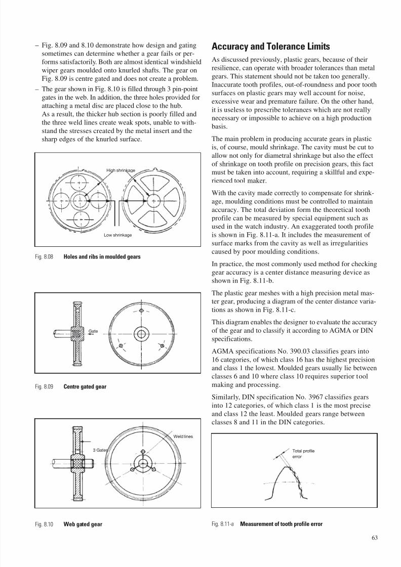
7/23/2019 f1236720 DuPont Engineering Polymers General Design Principles Module I
http://slidepdf.com/reader/full/f1236720-dupont-engineering-polymers-general-design-principles-module-i 65/155
– Fig. 8.09 and 8.10 demonstrate how design and gatingsometimes can determine whether a gear fails or per-
forms satisfactorily. Both are almost identical windshield
wiper gears moulded onto knurled shafts. The gear onFig. 8.09 is centre gated and does not create a problem.
– The gear shown in Fig. 8.10 is filled through 3 pin-point
gates in the web. In addition, the three holes provided forattaching a metal disc are placed close to the hub.
As a result, the thicker hub section is poorly filled and
the three weld lines create weak spots, unable to with-
stand the stresses created by the metal insert and thesharp edges of the knurled surface.
Accuracy and Tolerance Limits
As discussed previously, plastic gears, because of their
resilience, can operate with broader tolerances than metal
gears. This statement should not be taken too generally.Inaccurate tooth profiles, out-of-roundness and poor tooth
surfaces on plastic gears may well account for noise,
excessive wear and premature failure. On the other hand,it is useless to prescribe tolerances which are not reallynecessary or impossible to achieve on a high production
basis.
The main problem in producing accurate gears in plastic
is, of course, mould shrinkage. The cavity must be cut to
allow not only for diametral shrinkage but also the effect
of shrinkage on tooth profile on precision gears, this factmust be taken into account, requiring a skillful and expe-
rienced tool maker.
With the cavity made correctly to compensate for shrink-
age, moulding conditions must be controlled to maintainaccuracy. The total deviation form the theoretical tooth
profile can be measured by special equipment such asused in the watch industry. An exaggerated tooth profile
is shown in Fig. 8.11-a. It includes the measurement of
surface marks from the cavity as well as irregularities
caused by poor moulding conditions.
In practice, the most commonly used method for checking
gear accuracy is a center distance measuring device asshown in Fig. 8.11-b.
The plastic gear meshes with a high precision metal mas-ter gear, producing a diagram of the center distance varia-
tions as shown in Fig. 8.11-c.
This diagram enables the designer to evaluate the accuracy
of the gear and to classify it according to AGMA or DIN
specifications.
AGMA specifications No. 390.03 classifies gears into
16 categories, of which class 16 has the highest precision
and class 1 the lowest. Moulded gears usually lie betweenclasses 6 and 10 where class 10 requires superior tool
making and processing.
Similarly, DIN specification No. 3967 classifies gearsinto 12 categories, of which class 1 is the most precise
and class 12 the least. Moulded gears range between
classes 8 and 11 in the DIN categories.
63
Low shrinkage
High shrinkage
Gate
3 Gates
Weld lines
Fig. 8.08 Holes and ribs in moulded gears
Fig. 8.09 Centre gated gear
Fig. 8.10 Web gated gear Fig. 8.11-a Measurement of tooth profile error
Total profile
error
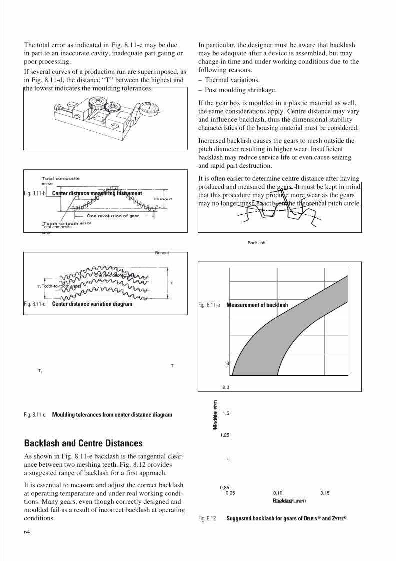
7/23/2019 f1236720 DuPont Engineering Polymers General Design Principles Module I
http://slidepdf.com/reader/full/f1236720-dupont-engineering-polymers-general-design-principles-module-i 66/155
The total error as indicated in Fig. 8.11-c may be duein part to an inaccurate cavity, inadequate part gating or
poor processing.
If several curves of a production run are superimposed, as
in Fig. 8.11-d, the distance “T” between the highest and
the lowest indicates the moulding tolerances.
Backlash and Centre Distances
As shown in Fig. 8.11-e backlash is the tangential clear-
ance between two meshing teeth. Fig. 8.12 provides
a suggested range of backlash for a first approach.
It is essential to measure and adjust the correct backlash
at operating temperature and under real working condi-tions. Many gears, even though correctly designed and
moulded fail as a result of incorrect backlash at operating
conditions.
In particular, the designer must be aware that backlashmay be adequate after a device is assembled, but may
change in time and under working conditions due to the
following reasons:
– Thermal variations.
– Post moulding shrinkage.
If the gear box is moulded in a plastic material as well,the same considerations apply. Centre distance may vary
and influence backlash, thus the dimensional stability
characteristics of the housing material must be considered.
Increased backlash causes the gears to mesh outside the
pitch diameter resulting in higher wear. Insufficient
backlash may reduce service life or even cause seizing
and rapid part destruction.
It is often easier to determine centre distance after having
produced and measured the gears. It must be kept in mind
that this procedure may produce more wear as the gearsmay no longer mesh exactly on the theoretical pitch circle.
64
Fig. 8.11-b Center distance measuring instrument
Fig. 8.11-c Center distance variation diagram
Fig. 8.11-d Moulding tolerances from center distance diagram
Backlash
Fig. 8.11-e Measurement of backlash
0,10 0,150,05
1
0,85
1,25
1,5
2,0
3
Backlash, mm
M o d u l e , m m
Fig. 8.12 Suggested backlash for gears of DELRIN® and ZYTEL®
Backlash, mm
M o d u l e , m m
Total composite
error
Runout
One revolution of gear
Tooth-to-tooth error
T1
T
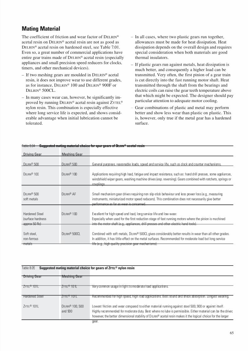
7/23/2019 f1236720 DuPont Engineering Polymers General Design Principles Module I
http://slidepdf.com/reader/full/f1236720-dupont-engineering-polymers-general-design-principles-module-i 67/155
Mating Material
The coefficient of friction and wear factor of DELRIN®
acetal resin on DELRIN® acetal resin are not as good as
DELRIN® acetal resin on hardened steel, see Table 7.01.Even so, a great number of commercial applications have
entire gear trains made of DELRIN® acetal resin (especially
appliances and small precision speed reducers for clocks,timers, and other mechanical devices).
– If two meshing gears are moulded in DELRIN® acetalresin, it does not improve wear to use different grades,
as for instance, DELRIN® 100 and DELRIN® 900F or
DELRIN® 500CL.
– In many cases wear can, however, be significantly im-
proved by running DELRIN® acetal resin against ZYTEL®
nylon resin. This combination is especially effective
where long service life is expected, and shows consid-
erable advantage when initial lubrication cannot be
tolerated.
– In all cases, where two plastic gears run together,
allowances must be made for heat dissipation. Heatdissipation depends on the overall design and requires
special consideration when both materials are good
thermal insulators.
– If plastic gears run against metals, heat dissipation is
much better, and consequently a higher load can betransmitted. Very often, the first pinion of a gear train
is cut directly into the fast running motor shaft. Heat
transmitted through the shaft from the bearings and
electric coils can raise the gear teeth temperature abovethat which might be expected. The designer should pay
particular attention to adequate motor cooling.
– Gear combinations of plastic and metal may perform
better and show less wear than plastic on plastic. This
is, however, only true if the metal gear has a hardened
surface.
65
Table 8.05 Suggested mating material choice for gears of ZYTEL® nylon resin
Driving Gear Meshing Gear
ZYTEL® 101L ZYTEL® 101L Very common usage in light to moderate load applications.
Hardened Steel ZYTEL® 101L Recommended for high speed, high load applications. Best sound and shock absorption. Longest wearing.
ZYTEL®
101L DELRIN®
100, 500 Lowest friction and wear compared to either material running against steel 500, 900 or against itself.and 900 Highly recommended for moderate duty. Best where no lube is permissible. Either material can be the driver,
however, the better dimensional stability of DELRIN® acetal resin makes it the logical choice for the larger
gear.
Table 8.04 Suggested mating material choice for spur gears of DELRIN® acetal resin
Driving Gear Meshing Gear
DELRIN® 500 DELRIN® 500 General purposes, reasonable loads, speed and service life, such as clock and counter mechanisms.
DELRIN® 100 DELRIN® 100 Applications requiring high load, fatigue and impact resistance, such as: hand drill presses, some appliances,
windshield wiper gears, washing machine drives (esp. reversing). Gears combined with ratchets, springs or
couplings.
DELRIN® 500 DELRIN® AF Small mechanism gear drives requiring non slip-stick behaviour and less power loss (e.g., measuring
soft metals instruments, miniaturized motor speed reducers). This combination does not necessarily give better
performance as far as wear is concerned.
Hardened Steel DELRIN® 100 Excellent for high speed and load, long service life and low wear.
(surface hardness Especially when used for the first reduction stage of fast running motors where the pinion is machined
approx 50 Rc) into the motor shaft (e.g., appliances, drill presses and other electric hand tools).
Soft steel, DELRIN® 500CL Combined with soft metals, DELRIN® 500CL gives considerably better results in wear than all other grades.
non-ferrous In addition, it has little effect on the metal surfaces. Recommended for moderate load but long service
metals life (e.g., high quality precision gear mechanisms).
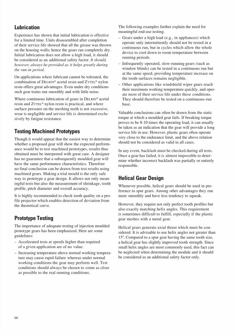
7/23/2019 f1236720 DuPont Engineering Polymers General Design Principles Module I
http://slidepdf.com/reader/full/f1236720-dupont-engineering-polymers-general-design-principles-module-i 68/155
Lubrication
Experience has shown that initial lubrication is effective
for a limited time. Units disassembled after completion
of their service life showed that all the grease was thrownon the housing walls; hence the gears ran completely dry.
Initial lubrication does not allow a high load, it should
be considered as an additional safety factor. It should,however, always be provided as it helps greatly during
the run-in period.
On applications where lubricant cannot be tolerated, the
combination of DELRIN® acetal resin and ZYTEL® nylon
resin offers great advantages. Even under dry conditionssuch gear trains run smoothly and with little noise.
Where continuous lubrication of gears in DELRIN® acetal
resin and ZYTEL® nylon resin is practical, and where
surface pressure on the meshing teeth is not excessive,wear is negligible and service life is determined exclu-
sively by fatigue resistance.
Testing Machined Prototypes
Though it would appear that the easiest way to determine
whether a proposed gear will show the expected perform-
ance would be to test machined prototypes, results thus
obtained must be interpreted with great care. A designerhas no guarantee that a subsequently moulded gear will
have the same performance characteristics. Therefore
no final conclusion can be drawn from test results using
machined gears. Making a trial mould is the only safeway to prototype a gear design. It allows not only mean-
ingful tests but also the measurement of shrinkage, tooth
profile, pitch diameter and overall accuracy.
It is highly recommended to check tooth quality on a pro-file projector which enables detection of deviation from
the theoretical curve.
Prototype Testing
The importance of adequate testing of injection mouldedprototype gears has been emphasized. Here are some
guidelines:
– Accelerated tests at speeds higher than required
of a given application are of no value.
– Increasing temperature above normal working tempera-
ture may cause rapid failure whereas under normal
working conditions the gear may perform well. Test
conditions should always be chosen to come as closeas possible to the real running conditions.
The following examples further explain the need formeaningful end-use testing.
– Gears under a high load (e.g., in appliances) which
operate only intermittently should not be tested in a
continuous run, but in cycles which allow the whole
device to cool down to room temperature between
running periods.– Infrequently operated, slow-running gears (such as
window blinds) can be tested in a continuous run but
at the same speed, providing temperature increase on
the tooth surfaces remains negligible.
– Other applications like windshield wiper gears reach
their maximum working temperature quickly, and oper-
ate most of their service life under these conditions.They should therefore be tested on a continuous-run
base.
Valuable conclusions can often be drawn from the static
torque at which a moulded gear fails. If breaking torqueproves to be 8-10 times the operating load, it can usually
be taken as an indication that the gear will provide a long
service life in use. However, plastic gears often operate
very close to the endurance limit, and the above relationshould not be considered as valid in all cases.
In any event, backlash must be checked during all tests.
Once a gear has failed, it is almost impossible to deter-
mine whether incorrect backlash was partially or entirelyresponsible.
Helical Gear DesignWhenever possible, helical gears should be used in pre-
ference to spur gears. Among other advantages they runmore smoothly and have less tendency to squeak.
However, they require not only perfect tooth profiles but
also exactly matching helix angles. This requirementis sometimes difficult to fulfill, especially if the plastic
gear meshes with a metal gear.
Helical gears generate axial thrust which must be con-
sidered. It is advisable to use helix angles not greater than15°. Compared to a spur gear having the same tooth size,
a helical gear has slightly improved tooth strength. Since
small helix angles are most commonly used, this fact can
be neglected when determining the module and it shouldbe considered as an additional safety factor only.
66
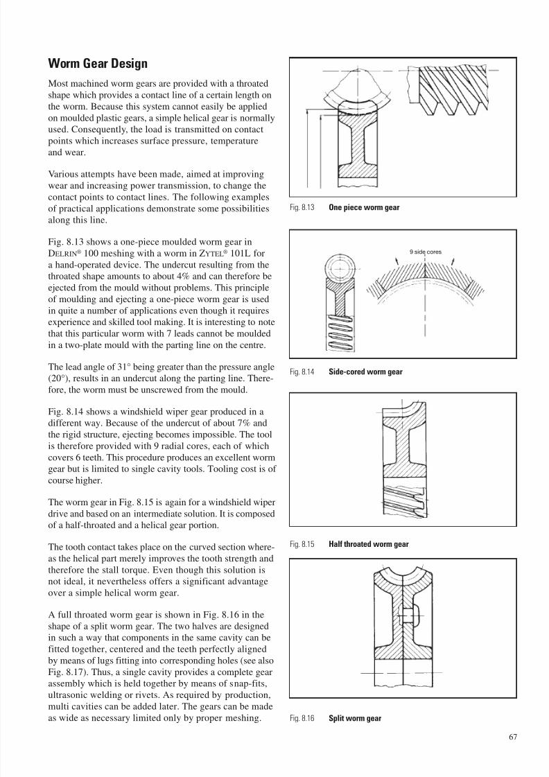
7/23/2019 f1236720 DuPont Engineering Polymers General Design Principles Module I
http://slidepdf.com/reader/full/f1236720-dupont-engineering-polymers-general-design-principles-module-i 69/155
Worm Gear Design
Most machined worm gears are provided with a throated
shape which provides a contact line of a certain length on
the worm. Because this system cannot easily be applied
on moulded plastic gears, a simple helical gear is normallyused. Consequently, the load is transmitted on contact
points which increases surface pressure, temperature
and wear.
Various attempts have been made, aimed at improving
wear and increasing power transmission, to change the
contact points to contact lines. The following examples
of practical applications demonstrate some possibilitiesalong this line.
Fig. 8.13 shows a one-piece moulded worm gear in
DELRIN® 100 meshing with a worm in ZYTEL® 101L for
a hand-operated device. The undercut resulting from the
throated shape amounts to about 4% and can therefore beejected from the mould without problems. This principle
of moulding and ejecting a one-piece worm gear is used
in quite a number of applications even though it requiresexperience and skilled tool making. It is interesting to note
that this particular worm with 7 leads cannot be moulded
in a two-plate mould with the parting line on the centre.
The lead angle of 31° being greater than the pressure angle(20°), results in an undercut along the parting line. There-
fore, the worm must be unscrewed from the mould.
Fig. 8.14 shows a windshield wiper gear produced in adifferent way. Because of the undercut of about 7% and
the rigid structure, ejecting becomes impossible. The tool
is therefore provided with 9 radial cores, each of which
covers 6 teeth. This procedure produces an excellent wormgear but is limited to single cavity tools. Tooling cost is of
course higher.
The worm gear in Fig. 8.15 is again for a windshield wiper
drive and based on an intermediate solution. It is composed
of a half-throated and a helical gear portion.
The tooth contact takes place on the curved section where-as the helical part merely improves the tooth strength and
therefore the stall torque. Even though this solution isnot ideal, it nevertheless offers a significant advantage
over a simple helical worm gear.
A full throated worm gear is shown in Fig. 8.16 in the
shape of a split worm gear. The two halves are designedin such a way that components in the same cavity can be
fitted together, centered and the teeth perfectly aligned
by means of lugs fitting into corresponding holes (see also
Fig. 8.17). Thus, a single cavity provides a complete gear
assembly which is held together by means of snap-fits,ultrasonic welding or rivets. As required by production,
multi cavities can be added later. The gears can be made
as wide as necessary limited only by proper meshing.
67
Fig. 8.13 One piece worm gear
Fig. 8.16 Split worm gear
Fig. 8.15 Half throated worm gear
Fig. 8.14 Side-cored worm gear
9 side cores

7/23/2019 f1236720 DuPont Engineering Polymers General Design Principles Module I
http://slidepdf.com/reader/full/f1236720-dupont-engineering-polymers-general-design-principles-module-i 70/155
This design comes closest to the classic machined metalfull throated worm gear, and tooling costs are no higher
than for the gear shown in Fig. 8.15. Split worm gears are
especially recommended for larger worm diameters,
where performance is improved considerably.
The advantage of throated over helical worm gears stems
primarily from the load being spread over a larger areaof the tooth, resulting in lower localized temperature
and reduced bending stress. Tests with the split wormgear show it to be superior to a helical worm gear by
a factor of 2-4.
An example of a snap-fit helical gear is shown in Fig. 8.17.
Certain limitations should be kept in mind in the design
of these throated worm take-off gears when compared tosimple helical gears, as follows:
– Higher tooling cost.
– Requirement of perfect centering of worm and worm
gear. Even small displacements cause the load to becarried by only a portion of the tooth width, resulting
in increased wear or rapid failure.
– The worm gear drive is more sensitive to discrepancies
of the lead angles which must match perfectly.
– The worm and the gear must be assembled in a certain
way. If for instance the worm is mounted first into the
housing a throated gear can be introduced only in
a radial direction, whereas a simple helical gear (ora gear as shown in Fig. 8.13) can be mounted sidewise.
Worm gear drives allow high speed reductions with onlytwo elements. Consequently, they often are used in
connection with fast running motors, with the worm cut
directly or rolled into the metal shaft.
Since the requirements are quite different in variousapplications, the performance and limitations of worm
gears in DELRIN® acetal resin and ZYTEL® nylon resin
will depend upon the specific application.
For instance, a windshield wiper gear may run repeatedly
for a considerable length of time and at high temperature.
It can, in addition, be submitted to severe stalling torquesif the windshield wiper blades are frozen. Since this hap-
pens at low temperatures, the gear diameter is smaller dueto thermal contraction, causing the teeth to be loaded
closer to the tip and thus increasing stress. Often it is thiscondition which controls the gear design.
On the contrary, an electric car window drive works undernormal conditions only a few seconds at a time, with long
intervals. Consequently, where is no time for a tempera-
ture rise and the gear can thus withstand higher loads.
Since the total service life, compared to a wind-shieldwiper, is very short, wear is rarely a problem. Many of
these power window mechanisms will lock up substantial
torque with the window closed. The gear must be strongenough that creep does not cause significant tooth distor-tion, particularly under closed car summer conditions.
In appliances, requirements are again quite different.The working time is usually indicated on the device and
strictly limited to a few minutes at a time. This allows the
use of smaller motors which are overloaded, heating up
very fast and transmitting temperatures to the shaft andthe worm. If the appliance is used as prescribed, tempera-
ture may not exceed a reasonable limit. If, however, the
devices are used longer or at frequent intervals, tempera-
ture can reach a level at which high wear and premature
failure can occur.These examples demonstrate the necessity of carefully
defining the expected working conditions, and of design-ing and dimensioning the worm and gear accordingly.
68
Variation of the same design
Fig. 8.17 Snap-fit split worm gear
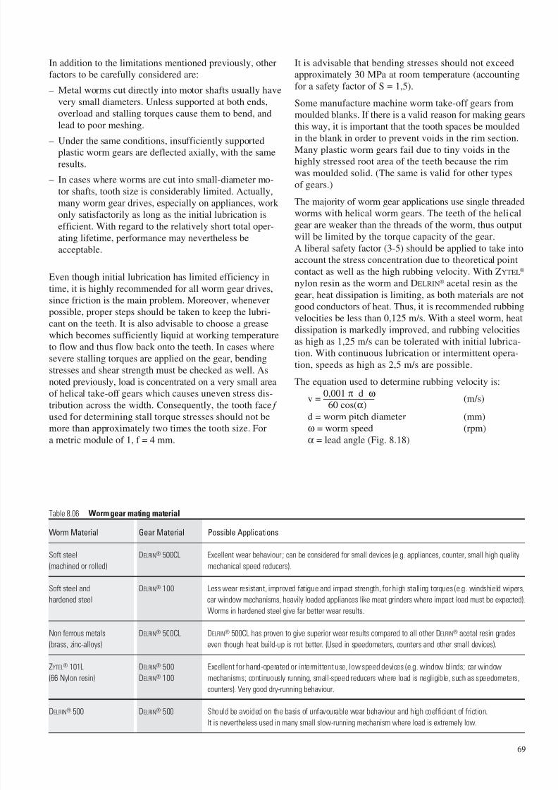
7/23/2019 f1236720 DuPont Engineering Polymers General Design Principles Module I
http://slidepdf.com/reader/full/f1236720-dupont-engineering-polymers-general-design-principles-module-i 71/155
In addition to the limitations mentioned previously, other
factors to be carefully considered are:
– Metal worms cut directly into motor shafts usually have
very small diameters. Unless supported at both ends,
overload and stalling torques cause them to bend, and
lead to poor meshing.
– Under the same conditions, insufficiently supportedplastic worm gears are deflected axially, with the same
results.
– In cases where worms are cut into small-diameter mo-
tor shafts, tooth size is considerably limited. Actually,
many worm gear drives, especially on appliances, work
only satisfactorily as long as the initial lubrication is
efficient. With regard to the relatively short total oper-
ating lifetime, performance may nevertheless be
acceptable.
Even though initial lubrication has limited efficiency intime, it is highly recommended for all worm gear drives,
since friction is the main problem. Moreover, whenever
possible, proper steps should be taken to keep the lubri-
cant on the teeth. It is also advisable to choose a grease
which becomes sufficiently liquid at working temperature
to flow and thus flow back onto the teeth. In cases where
severe stalling torques are applied on the gear, bending
stresses and shear strength must be checked as well. As
noted previously, load is concentrated on a very small area
of helical take-off gears which causes uneven stress dis-
tribution across the width. Consequently, the tooth face f
used for determining stall torque stresses should not bemore than approximately two times the tooth size. For
a metric module of 1, f = 4 mm.
It is advisable that bending stresses should not exceedapproximately 30 MPa at room temperature (accounting
for a safety factor of S = 1,5).
Some manufacture machine worm take-off gears frommoulded blanks. If there is a valid reason for making gears
this way, it is important that the tooth spaces be moulded
in the blank in order to prevent voids in the rim section.Many plastic worm gears fail due to tiny voids in thehighly stressed root area of the teeth because the rim
was moulded solid. (The same is valid for other types
of gears.)
The majority of worm gear applications use single threadedworms with helical worm gears. The teeth of the helical
gear are weaker than the threads of the worm, thus output
will be limited by the torque capacity of the gear.
A liberal safety factor (3-5) should be applied to take intoaccount the stress concentration due to theoretical point
contact as well as the high rubbing velocity. With ZYTEL®
nylon resin as the worm and DELRIN® acetal resin as the
gear, heat dissipation is limiting, as both materials are notgood conductors of heat. Thus, it is recommended rubbing
velocities be less than 0,125 m/s. With a steel worm, heat
dissipation is markedly improved, and rubbing velocities
as high as 1,25 m/s can be tolerated with initial lubrica-tion. With continuous lubrication or intermittent opera-
tion, speeds as high as 2,5 m/s are possible.
The equation used to determine rubbing velocity is:
v =0,001 π d ω
(m/s)60 cos(α)
d = worm pitch diameter (mm)ω = worm speed (rpm)
α = lead angle (Fig. 8.18)
69
Table 8.06 Worm gear mating material
Worm Material Gear Material Possible Applications
Soft steel DELRIN® 500CL Excellent wear behaviour ; can be considered for small devices (e.g. appliances, counter, small high quality(machined or rolled) mechanical speed reducers).
Soft steel and DELRIN® 100 Less wear resistant, improved fatigue and impact strength, for high stalling torques (e.g. windshield wipers,
hardened steel car window mechanisms, heavily loaded appliances like meat grinders where impact load must be expected).
Worms in hardened steel give far better wear results.
Non ferrous metals DELRIN® 500CL DELRIN® 500CL has proven to give superior wear results compared to all other DELRIN® acetal resin grades
(brass, zinc-alloys) even though heat build-up is not better. (Used in speedometers, counters and other small devices).
ZYTEL® 101L DELRIN® 500 Excellent for hand-operated or intermittent use, low speed devices (e.g. window blinds; car window
(66 Nylon resin) DELRIN® 100 mechanisms; continuously running, small-speed reducers where load is negligible, such as speedometers,
counters). Very good dry-running behaviour.
DELRIN® 500 DELRIN® 500 Should be avoided on the basis of unfavourable wear behaviour and high coefficient of friction.
It is nevertheless used in many small slow-running mechanism where load is extremely low.
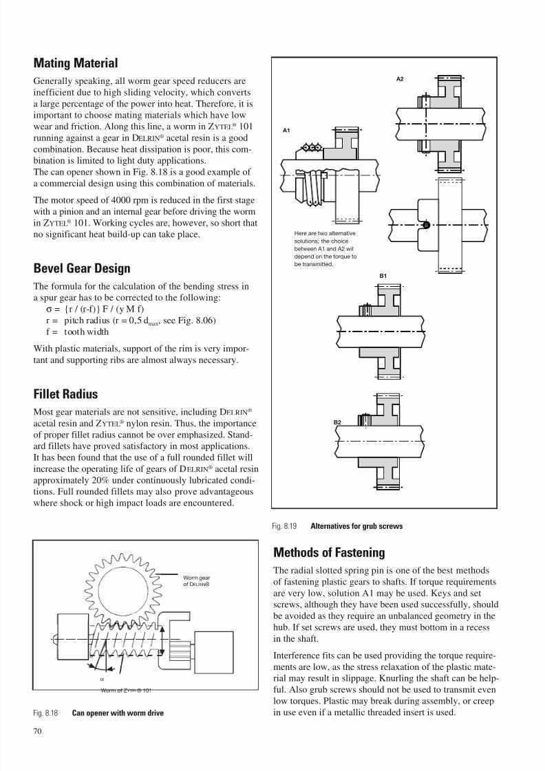
7/23/2019 f1236720 DuPont Engineering Polymers General Design Principles Module I
http://slidepdf.com/reader/full/f1236720-dupont-engineering-polymers-general-design-principles-module-i 72/155
Mating Material
Generally speaking, all worm gear speed reducers are
inefficient due to high sliding velocity, which converts
a large percentage of the power into heat. Therefore, it is
important to choose mating materials which have low
wear and friction. Along this line, a worm in ZYTEL® 101
running against a gear in DELRIN® acetal resin is a goodcombination. Because heat dissipation is poor, this com-
bination is limited to light duty applications.
The can opener shown in Fig. 8.18 is a good example of
a commercial design using this combination of materials.
The motor speed of 4000 rpm is reduced in the first stage
with a pinion and an internal gear before driving the worm
in ZYTEL® 101. Working cycles are, however, so short that
no significant heat build-up can take place.
Bevel Gear DesignThe formula for the calculation of the bending stress ina spur gear has to be corrected to the following:
σ = {r / (r-f)} F / (y M f)
r = pitch radius (r = 0,5 dmax, see Fig. 8.06)
f = tooth width
With plastic materials, support of the rim is very impor-
tant and supporting ribs are almost always necessary.
Fillet Radius
Most gear materials are not sensitive, including DELRIN®
acetal resin and ZYTEL® nylon resin. Thus, the importance
of proper fillet radius cannot be over emphasized. Stand-ard fillets have proved satisfactory in most applications.
It has been found that the use of a full rounded fillet will
increase the operating life of gears of DELRIN® acetal resin
approximately 20% under continuously lubricated condi-tions. Full rounded fillets may also prove advantageous
where shock or high impact loads are encountered.
Methods of Fastening
The radial slotted spring pin is one of the best methods
of fastening plastic gears to shafts. If torque requirements
are very low, solution A1 may be used. Keys and setscrews, although they have been used successfully, should
be avoided as they require an unbalanced geometry in the
hub. If set screws are used, they must bottom in a recess
in the shaft.
Interference fits can be used providing the torque require-
ments are low, as the stress relaxation of the plastic mate-
rial may result in slippage. Knurling the shaft can be help-ful. Also grub screws should not be used to transmit even
low torques. Plastic may break during assembly, or creep
in use even if a metallic threaded insert is used.
70
Worm gear
of DELRIN®
Worm of ZYTEL® 101
Fig. 8.18 Can opener with worm drive
A2
Here are two alternative
solutions; the choice
between A1 and A2 will
depend on the torque to
be transmitted.
B1
B2
Fig. 8.19 Alternatives for grub screws
d
α
A1
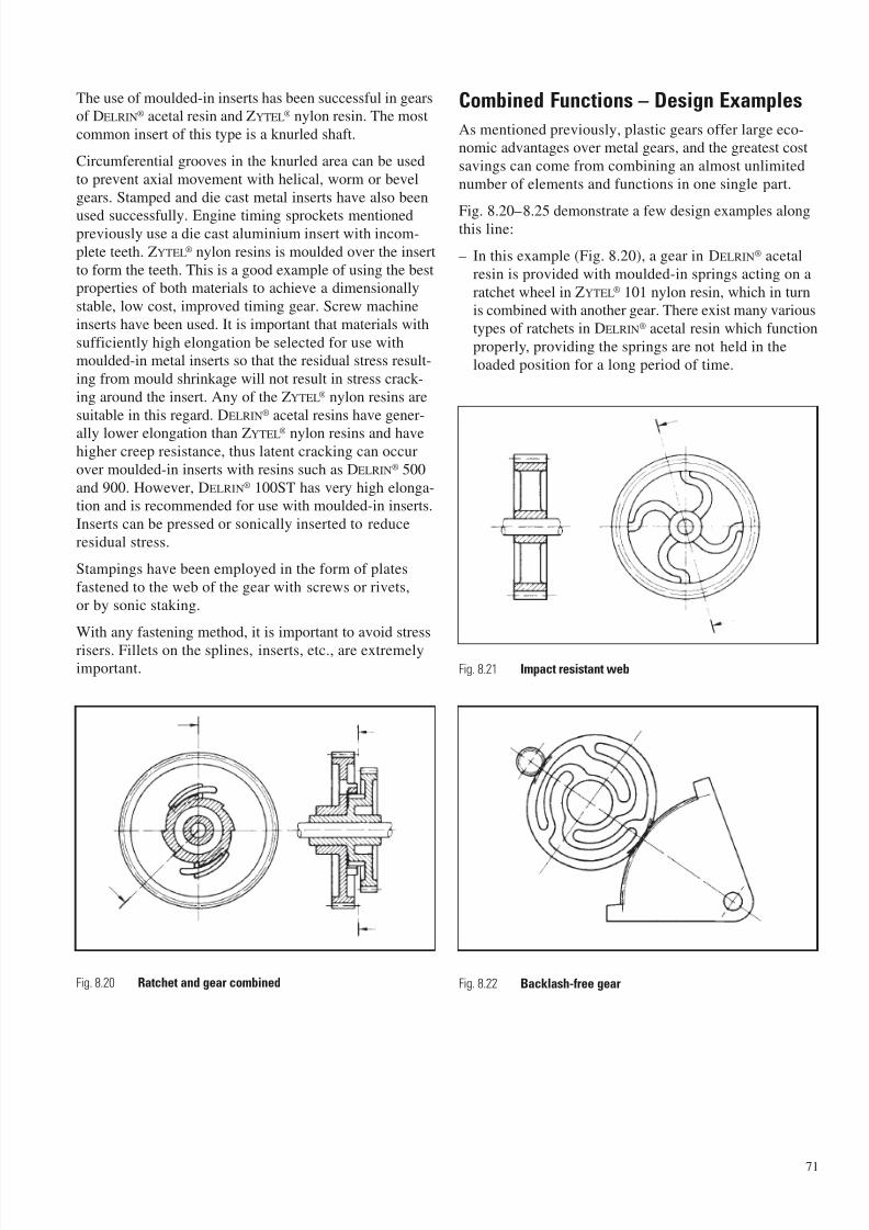
7/23/2019 f1236720 DuPont Engineering Polymers General Design Principles Module I
http://slidepdf.com/reader/full/f1236720-dupont-engineering-polymers-general-design-principles-module-i 73/155
The use of moulded-in inserts has been successful in gearsof DELRIN® acetal resin and ZYTEL® nylon resin. The most
common insert of this type is a knurled shaft.
Circumferential grooves in the knurled area can be used
to prevent axial movement with helical, worm or bevel
gears. Stamped and die cast metal inserts have also been
used successfully. Engine timing sprockets mentionedpreviously use a die cast aluminium insert with incom-
plete teeth. ZYTEL® nylon resins is moulded over the insert
to form the teeth. This is a good example of using the bestproperties of both materials to achieve a dimensionally
stable, low cost, improved timing gear. Screw machine
inserts have been used. It is important that materials with
sufficiently high elongation be selected for use withmoulded-in metal inserts so that the residual stress result-
ing from mould shrinkage will not result in stress crack-
ing around the insert. Any of the ZYTEL® nylon resins are
suitable in this regard. DELRIN® acetal resins have gener-
ally lower elongation than ZYTEL® nylon resins and havehigher creep resistance, thus latent cracking can occur
over moulded-in inserts with resins such as DELRIN® 500
and 900. However, DELRIN® 100ST has very high elonga-tion and is recommended for use with moulded-in inserts.
Inserts can be pressed or sonically inserted to reduce
residual stress.
Stampings have been employed in the form of plates
fastened to the web of the gear with screws or rivets,
or by sonic staking.
With any fastening method, it is important to avoid stress
risers. Fillets on the splines, inserts, etc., are extremelyimportant.
Combined Functions – Design Examples
As mentioned previously, plastic gears offer large eco-nomic advantages over metal gears, and the greatest cost
savings can come from combining an almost unlimited
number of elements and functions in one single part.
Fig. 8.20–8.25 demonstrate a few design examples alongthis line:
– In this example (Fig. 8.20), a gear in DELRIN® acetal
resin is provided with moulded-in springs acting on a
ratchet wheel in ZYTEL® 101 nylon resin, which in turnis combined with another gear. There exist many various
types of ratchets in DELRIN® acetal resin which function
properly, providing the springs are not held in the
loaded position for a long period of time.
71
Fig. 8.21 Impact resistant web
Fig. 8.22 Backlash-free gearFig. 8.20 Ratchet and gear combined
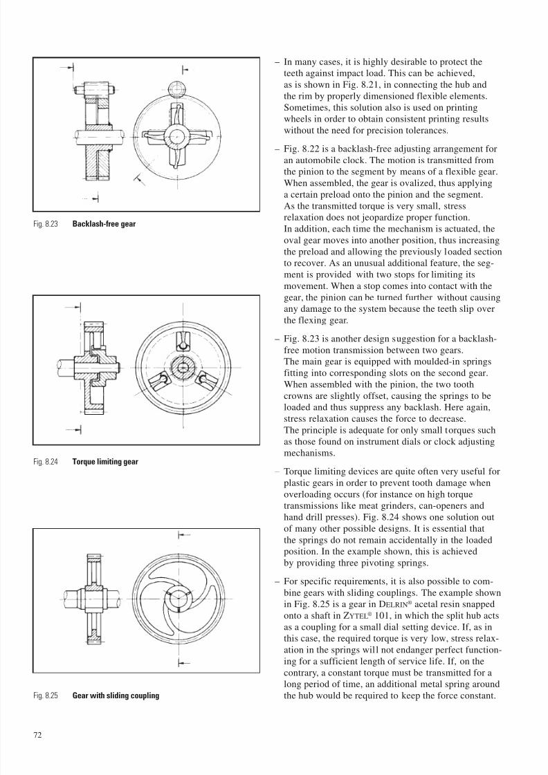
7/23/2019 f1236720 DuPont Engineering Polymers General Design Principles Module I
http://slidepdf.com/reader/full/f1236720-dupont-engineering-polymers-general-design-principles-module-i 74/155
– In many cases, it is highly desirable to protect theteeth against impact load. This can be achieved,
as is shown in Fig. 8.21, in connecting the hub and
the rim by properly dimensioned flexible elements.
Sometimes, this solution also is used on printingwheels in order to obtain consistent printing results
without the need for precision tolerances.
– Fig. 8.22 is a backlash-free adjusting arrangement for
an automobile clock. The motion is transmitted fromthe pinion to the segment by means of a flexible gear.
When assembled, the gear is ovalized, thus applying
a certain preload onto the pinion and the segment.
As the transmitted torque is very small, stressrelaxation does not jeopardize proper function.
In addition, each time the mechanism is actuated, the
oval gear moves into another position, thus increasing
the preload and allowing the previously loaded sectionto recover. As an unusual additional feature, the seg-
ment is provided with two stops for limiting itsmovement. When a stop comes into contact with the
gear, the pinion can be turned further without causingany damage to the system because the teeth slip over
the flexing gear.
– Fig. 8.23 is another design suggestion for a backlash-
free motion transmission between two gears.The main gear is equipped with moulded-in springs
fitting into corresponding slots on the second gear.
When assembled with the pinion, the two tooth
crowns are slightly offset, causing the springs to be
loaded and thus suppress any backlash. Here again,stress relaxation causes the force to decrease.
The principle is adequate for only small torques such
as those found on instrument dials or clock adjustingmechanisms.
– Torque limiting devices are quite often very useful for
plastic gears in order to prevent tooth damage when
overloading occurs (for instance on high torquetransmissions like meat grinders, can-openers and
hand drill presses). Fig. 8.24 shows one solution out
of many other possible designs. It is essential that
the springs do not remain accidentally in the loadedposition. In the example shown, this is achieved
by providing three pivoting springs.
– For specific requirements, it is also possible to com-
bine gears with sliding couplings. The example shownin Fig. 8.25 is a gear in DELRIN® acetal resin snapped
onto a shaft in ZYTEL® 101, in which the split hub acts
as a coupling for a small dial setting device. If, as inthis case, the required torque is very low, stress relax-
ation in the springs will not endanger perfect function-
ing for a sufficient length of service life. If, on the
contrary, a constant torque must be transmitted for along period of time, an additional metal spring around
the hub would be required to keep the force constant.
72
Fig. 8.24 Torque limiting gear
Fig. 8.25 Gear with sliding coupling
Fig. 8.23 Backlash-free gear
7/23/2019 f1236720 DuPont Engineering Polymers General Design Principles Module I
http://slidepdf.com/reader/full/f1236720-dupont-engineering-polymers-general-design-principles-module-i 75/155
When to use DELRIN® Acetal Resin
or ZYTEL® Nylon Resin
ZYTEL® nylon resin and DELRIN® acetal resin are excellent
gear materials, used extensively in a variety of applica-
tions. The choice of one over the other may at first seem
unclear, but as one examines the specific requirements of
the application, it becomes relatively easy. Although the
two materials are similar in many ways, they have distinct
property differences, and it is these differences upon which
the selection is made. Some guidelines are as follows:
ZYTEL® Nylon Resin
– Highest end-use temperature.
– Max. impact and shock absorption.
– Insert moulding.
– Max. abrasion resistance.
– Better resistance to weak acids and bases.
– Quieter running.
DELRIN® Acetal Resin
– Best dimensional stability.
– Integrally moulded springs.
– Running against soft metals.
– Low moisture absorption.
– Best resistance to solvents.
– Good stain resistance.
– Stiffer and stronger in higher humidity environment.
As previously pointed out, running DELRIN® acetal resinand ZYTEL® nylon resin against each other results in lower
wear and friction than either material running against
steel (not always true when high loads are encounteredand heat dissipation is controlling). Some designers have
used this combination in developing new, more efficient
gear systems.
When properties of DELRIN® acetal resin are needed,
DELRIN® 100 is the preferred gear material because it
has superior toughness and elongation to break versus
DELRIN® 500. DELRIN® 100 is the most viscous in the meltstate, and cannot always be used in hard to fill moulds.
DELRIN® 500 and 900 have been used successfully in many
such cases.
When ZYTEL® nylon resin is the chosen material,
ZYTEL® 101L is the most common material used.
ZYTEL® 103HSL, a heat stabilized version ofZYTEL® 101L, should be specified if the service life and
end use temperature are high.
Glass reinforced versions of either material should be
avoided. The glass fibres are very abrasive and the wear
rate of both the plastic gear and the mating gear will behigh. Gears which operate for extremely short periodsof time on an intermittent basis have been used with glass
reinforcement to improve stiffness, strength or dimen-
sional stability. Very careful testing is mandatory.
The moulding conditions must be controlled carefully, notonly for the usual purpose of maintaining gear accuracy,
but also because glass reinforced resins will exhibit large
differences in surface appearance with changes in mould-
ing conditions, particularly mould temperature. It is pos-sible to vary mould temperature without changing dimen-
sions, by compensating through adjustments in other
process variables. Thus, establish surface smoothnessspecifications to be sure the type of gear surface testedis reproduced in mass production.
73

7/23/2019 f1236720 DuPont Engineering Polymers General Design Principles Module I
http://slidepdf.com/reader/full/f1236720-dupont-engineering-polymers-general-design-principles-module-i 76/155
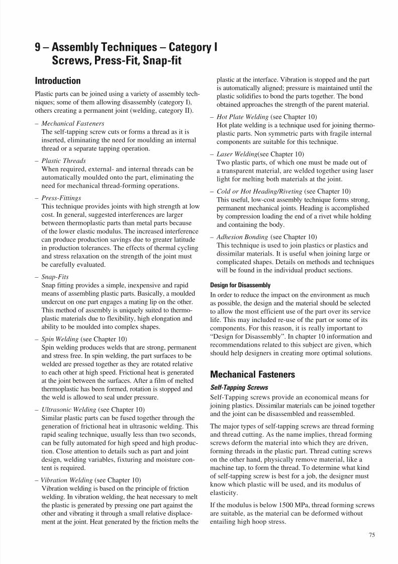
7/23/2019 f1236720 DuPont Engineering Polymers General Design Principles Module I
http://slidepdf.com/reader/full/f1236720-dupont-engineering-polymers-general-design-principles-module-i 77/155
Introduction
Plastic parts can be joined using a variety of assembly tech-
niques; some of them allowing disassembly (category I),
others creating a permanent joint (welding, category II).
– Mechanical Fasteners
The self-tapping screw cuts or forms a thread as it is
inserted, eliminating the need for moulding an internal
thread or a separate tapping operation.
– Plastic Threads
When required, external- and internal threads can be
automatically moulded onto the part, eliminating the
need for mechanical thread-forming operations.
– Press-FittingsThis technique provides joints with high strength at low
cost. In general, suggested interferences are larger
between thermoplastic parts than metal parts because
of the lower elastic modulus. The increased interference
can produce production savings due to greater latitude
in production tolerances. The effects of thermal cycling
and stress relaxation on the strength of the joint must
be carefully evaluated.
– Snap-Fits
Snap fitting provides a simple, inexpensive and rapid
means of assembling plastic parts. Basically, a mouldedundercut on one part engages a mating lip on the other.
This method of assembly is uniquely suited to thermo-
plastic materials due to flexibility, high elongation and
ability to be moulded into complex shapes.
– Spin Welding (see Chapter 10)
Spin welding produces welds that are strong, permanent
and stress free. In spin welding, the part surfaces to be
welded are pressed together as they are rotated relative
to each other at high speed. Frictional heat is generated
at the joint between the surfaces. After a film of melted
thermoplastic has been formed, rotation is stopped and
the weld is allowed to seal under pressure.
– Ultrasonic Welding (see Chapter 10)
Similar plastic parts can be fused together through the
generation of frictional heat in ultrasonic welding. This
rapid sealing technique, usually less than two seconds,
can be fully automated for high speed and high produc-
tion. Close attention to details such as part and joint
design, welding variables, fixturing and moisture con-
tent is required.
– Vibration Welding (see Chapter 10)
Vibration welding is based on the principle of friction
welding. In vibration welding, the heat necessary to melt
the plastic is generated by pressing one part against the
other and vibrating it through a small relative displace-
ment at the joint. Heat generated by the friction melts the
plastic at the interface. Vibration is stopped and the part
is automatically aligned; pressure is maintained until the
plastic solidifies to bond the parts together. The bondobtained approaches the strength of the parent material.
– Hot Plate Welding (see Chapter 10)
Hot plate welding is a technique used for joining thermo-
plastic parts. Non symmetric parts with fragile internal
components are suitable for this technique.
– Laser Welding(see Chapter 10)
Two plastic parts, of which one must be made out of
a transparent material, are welded together using laser
light for melting both materials at the joint.
– Cold or Hot Heading/Riveting (see Chapter 10)
This useful, low-cost assembly technique forms strong,permanent mechanical joints. Heading is accomplished
by compression loading the end of a rivet while holding
and containing the body.
– Adhesion Bonding (see Chapter 10)
This technique is used to join plastics or plastics and
dissimilar materials. It is useful when joining large or
complicated shapes. Details on methods and techniques
will be found in the individual product sections.
Design for Disassembly
In order to reduce the impact on the environment as muchas possible, the design and the material should be selected
to allow the most efficient use of the part over its service
life. This may included re-use of the part or some of its
components. For this reason, it is really important to
“Design for Disassembly”. In chapter 10 information and
recommendations related to this subject are given, which
should help designers in creating more optimal solutions.
Mechanical Fasteners
Self-Tapping Screws
Self-Tapping screws provide an economical means for joining plastics. Dissimilar materials can be joined togetherand the joint can be disassembled and reassembled.
The major types of self-tapping screws are thread formingand thread cutting. As the name implies, thread forming
screws deform the material into which they are driven,
forming threads in the plastic part. Thread cutting screws
on the other hand, physically remove material, like amachine tap, to form the thread. To determine what kind
of self-tapping screw is best for a job, the designer must
know which plastic will be used, and its modulus of
elasticity.If the modulus is below 1500 MPa, thread forming screws
are suitable, as the material can be deformed withoutentailing high hoop stress.
75
9 – Assembly Techniques – Category IScrews, Press-Fit, Snap-fit
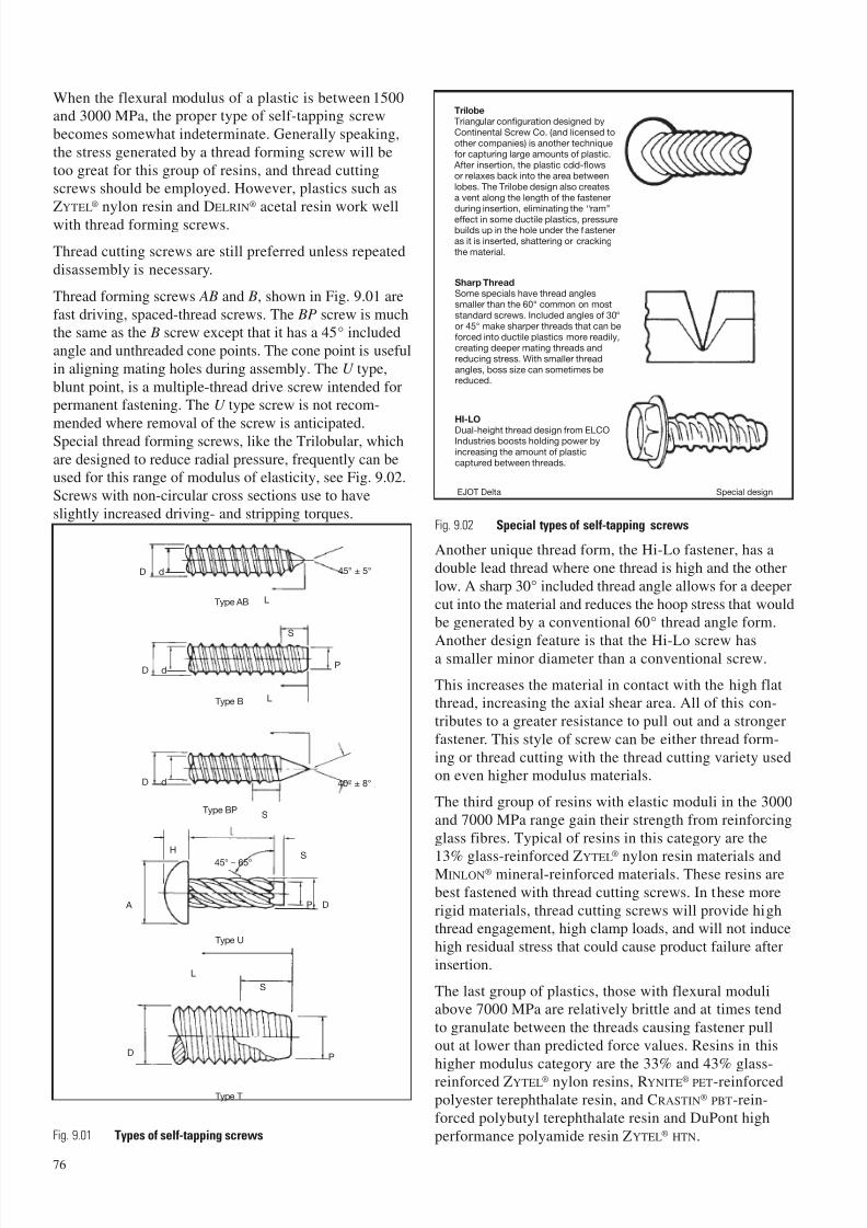
7/23/2019 f1236720 DuPont Engineering Polymers General Design Principles Module I
http://slidepdf.com/reader/full/f1236720-dupont-engineering-polymers-general-design-principles-module-i 78/155
When the flexural modulus of a plastic is between 1500and 3000 MPa, the proper type of self-tapping screw
becomes somewhat indeterminate. Generally speaking,
the stress generated by a thread forming screw will be
too great for this group of resins, and thread cuttingscrews should be employed. However, plastics such as
ZYTEL® nylon resin and DELRIN® acetal resin work well
with thread forming screws.
Thread cutting screws are still preferred unless repeated
disassembly is necessary.
Thread forming screws AB and B, shown in Fig. 9.01 are
fast driving, spaced-thread screws. The BP screw is muchthe same as the B screw except that it has a 45° included
angle and unthreaded cone points. The cone point is useful
in aligning mating holes during assembly. The U type,
blunt point, is a multiple-thread drive screw intended forpermanent fastening. The U type screw is not recom-
mended where removal of the screw is anticipated.Special thread forming screws, like the Trilobular, which
are designed to reduce radial pressure, frequently can beused for this range of modulus of elasticity, see Fig. 9.02.
Screws with non-circular cross sections use to have
slightly increased driving- and stripping torques.
Another unique thread form, the Hi-Lo fastener, has a
double lead thread where one thread is high and the other
low. A sharp 30° included thread angle allows for a deeper
cut into the material and reduces the hoop stress that wouldbe generated by a conventional 60° thread angle form.
Another design feature is that the Hi-Lo screw hasa smaller minor diameter than a conventional screw.
This increases the material in contact with the high flatthread, increasing the axial shear area. All of this con-
tributes to a greater resistance to pull out and a stronger
fastener. This style of screw can be either thread form-
ing or thread cutting with the thread cutting variety usedon even higher modulus materials.
The third group of resins with elastic moduli in the 3000
and 7000 MPa range gain their strength from reinforcing
glass fibres. Typical of resins in this category are the
13% glass-reinforced ZYTEL®
nylon resin materials andMINLON® mineral-reinforced materials. These resins are
best fastened with thread cutting screws. In these more
rigid materials, thread cutting screws will provide highthread engagement, high clamp loads, and will not induce
high residual stress that could cause product failure after
insertion.
The last group of plastics, those with flexural moduliabove 7000 MPa are relatively brittle and at times tend
to granulate between the threads causing fastener pull
out at lower than predicted force values. Resins in this
higher modulus category are the 33% and 43% glass-
reinforced ZYTEL® nylon resins, RYNITE® PET-reinforcedpolyester terephthalate resin, and CRASTIN® PBT-rein-
forced polybutyl terephthalate resin and DuPont high
performance polyamide resin ZYTEL® HTN.
76
Trilobe
Triangular configuration designed byContinental Screw Co. (and licensed toother companies) is another techniquefor capturing large amounts of plastic.
After insertion, the plastic cold-flowsor relaxes back into the area betweenlobes. The Trilobe design also createsa vent along the length of the fastenerduring insertion, eliminating the ‘‘ram’’effect in some ductile plastics, pressurebuilds up in the hole under the fasteneras it is inserted, shattering or crackingthe material.
Sharp Thread
Some specials have thread anglessmaller than the 60° common on moststandard screws. Included angles of 30°or 45° make sharper threads that can beforced into ductile plastics more readily,creating deeper mating threads andreducing stress. With smaller threadangles, boss size can sometimes bereduced.
HI-LO
Dual-height thread design from ELCOIndustries boosts holding power byincreasing the amount of plasticcaptured between threads.
D d
L
45° ± 5°
LType AB
Type B
Type BP
Type U
S
P
D d
A
HS
P D
45° – 65°
Type T
L
S
PD
S
40° ± 8°
D d
Fig. 9.01 Types of self-tapping screws
Fig. 9.02 Special types of self-tapping screws
EJOT Delta Special design
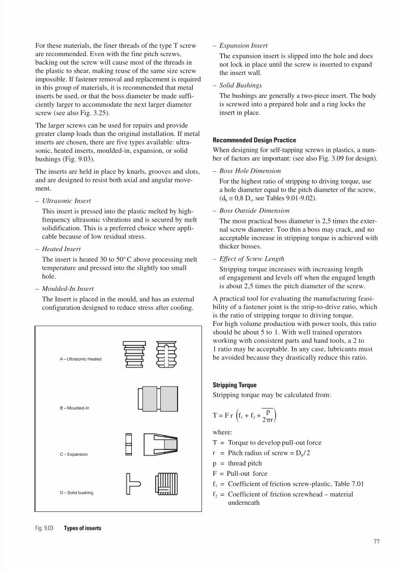
7/23/2019 f1236720 DuPont Engineering Polymers General Design Principles Module I
http://slidepdf.com/reader/full/f1236720-dupont-engineering-polymers-general-design-principles-module-i 79/155
For these materials, the finer threads of the type T screware recommended. Even with the fine pitch screws,
backing out the screw will cause most of the threads in
the plastic to shear, making reuse of the same size screw
impossible. If fastener removal and replacement is requiredin this group of materials, it is recommended that metal
inserts be used, or that the boss diameter be made suffi-
ciently larger to accommodate the next larger diameter
screw (see also Fig. 3.25).
The larger screws can be used for repairs and providegreater clamp loads than the original installation. If metal
inserts are chosen, there are five types available: ultra-
sonic, heated inserts, moulded-in, expansion, or solid
bushings (Fig. 9.03).
The inserts are held in place by knurls, grooves and slots,
and are designed to resist both axial and angular move-ment.
– Ultrasonic Insert
This insert is pressed into the plastic melted by high-
frequency ultrasonic vibrations and is secured by melt
solidification. This is a preferred choice where appli-cable because of low residual stress.
– Heated Insert
The insert is heated 30 to 50°C above processing melt
temperature and pressed into the slightly too small
hole.
– Moulded-In Insert
The Insert is placed in the mould, and has an externalconfiguration designed to reduce stress after cooling.
– Expansion Insert
The expansion insert is slipped into the hole and does
not lock in place until the screw is inserted to expandthe insert wall.
– Solid Bushings
The bushings are generally a two-piece insert. The body
is screwed into a prepared hole and a ring locks the
insert in place.
Recommended Design Practice
When designing for self-tapping screws in plastics, a num-
ber of factors are important: (see also Fig. 3.09 for design).
– Boss Hole Dimension
For the highest ratio of stripping to driving torque, use
a hole diameter equal to the pitch diameter of the screw,
(dh ≅ 0,8 Ds, see Tables 9.01-9.02). – Boss Outside Dimension
The most practical boss diameter is 2,5 times the exter-
nal screw diameter. Too thin a boss may crack, and no
acceptable increase in stripping torque is achieved withthicker bosses.
– Effect of Screw Length
Stripping torque increases with increasing length
of engagement and levels off when the engaged length
is about 2,5 times the pitch diameter of the screw.
A practical tool for evaluating the manufacturing feasi-bility of a fastener joint is the strip-to-drive ratio, which
is the ratio of stripping torque to driving torque.
For high volume production with power tools, this ratio
should be about 5 to 1. With well trained operatorsworking with consistent parts and hand tools, a 2 to
1 ratio may be acceptable. In any case, lubricants must
be avoided because they drastically reduce this ratio.
Stripping Torque
Stripping torque may be calculated from:
T = F r f 1 + f 2 +p
2r
where:
T = Torque to develop pull-out force
r = Pitch radius of screw = Dp / 2
p = thread pitch
F = Pull-out force
f 1 = Coefficient of friction screw-plastic, Table 7.01
f 2 = Coefficient of friction screwhead – material
underneath
77
A – Ultrasonic Heated
B – Moulded-In
C – Expansion
D – Solid bushing
Fig. 9.03 Types of inserts
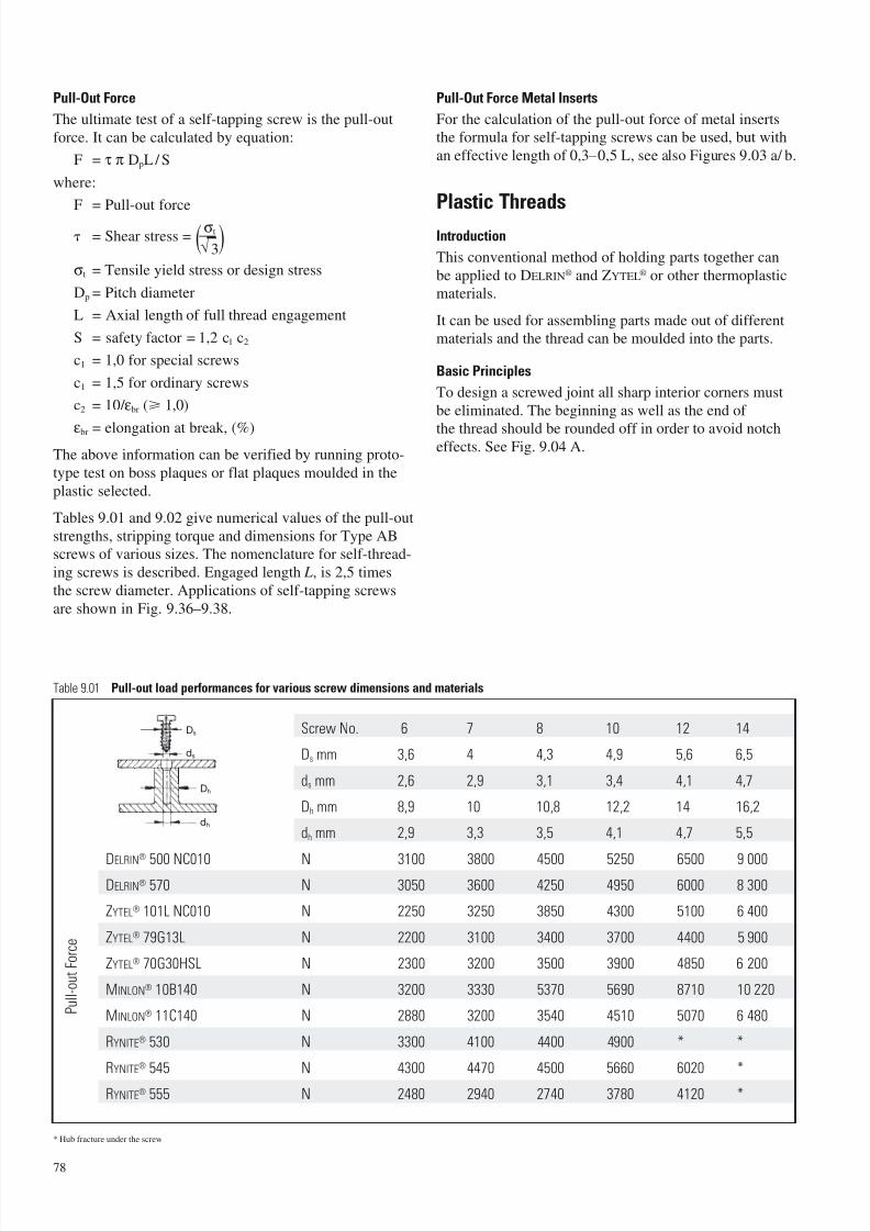
7/23/2019 f1236720 DuPont Engineering Polymers General Design Principles Module I
http://slidepdf.com/reader/full/f1236720-dupont-engineering-polymers-general-design-principles-module-i 80/155
78
Screw No. 6 7 8 10 12 14
Ds mm 3,6 4 4,3 4,9 5,6 6,5
ds mm 2,6 2,9 3,1 3,4 4,1 4,7
Dh mm 8,9 10 10,8 12,2 14 16,2
dh mm 2,9 3,3 3,5 4,1 4,7 5,5
DELRIN®
500 NC010 N 3100 3800 4500 5250 6500 9 000DELRIN® 570 N 3050 3600 4250 4950 6000 8 300
ZYTEL® 101L NC010 N 2250 3250 3850 4300 5100 6 400
ZYTEL® 79G13L N 2200 3100 3400 3700 4400 5 900
ZYTEL® 70G30HSL N 2300 3200 3500 3900 4850 6 200
MINLON® 10B140 N 3200 3330 5370 5690 8710 10 220
MINLON® 11C140 N 2880 3200 3540 4510 5070 6 480
RYNITE® 530 N 3300 4100 4400 4900 * *
RYNITE® 545 N 4300 4470 4500 5660 6020 *
RYNITE® 555 N 2480 2940 2740 3780 4120 *
Table 9.01 Pull-out load performances for various screw dimensions and materials
Ds
ds
Dh
dh
P u l l - o u t F o r c e
* Hub fracture under the screw
Pull-Out Force
The ultimate test of a self-tapping screw is the pull-out
force. It can be calculated by equation:
F = τ π DpL/ S
where:
F = Pull-out force
= Shear stress = σt
√ 3
σt = Tensile yield stress or design stress
Dp = Pitch diameter
L = Axial length of full thread engagement
S = safety factor = 1,2 c1 c2
c1 = 1,0 for special screws
c1 = 1,5 for ordinary screws
c2 = 10/ εbr ( 1,0)
εbr = elongation at break, (%)The above information can be verified by running proto-
type test on boss plaques or flat plaques moulded in the
plastic selected.
Tables 9.01 and 9.02 give numerical values of the pull-out
strengths, stripping torque and dimensions for Type AB
screws of various sizes. The nomenclature for self-thread-
ing screws is described. Engaged length L, is 2,5 times
the screw diameter. Applications of self-tapping screws
are shown in Fig. 9.36–9.38.
Pull-Out Force Metal Inserts
For the calculation of the pull-out force of metal insertsthe formula for self-tapping screws can be used, but with
an effective length of 0,3–0,5 L, see also Figures 9.03 a/ b.
Plastic Threads
Introduction
This conventional method of holding parts together can
be applied to DELRIN® and ZYTEL® or other thermoplasticmaterials.
It can be used for assembling parts made out of differentmaterials and the thread can be moulded into the parts.
Basic Principles
To design a screwed joint all sharp interior corners must
be eliminated. The beginning as well as the end of
the thread should be rounded off in order to avoid notcheffects. See Fig. 9.04 A.
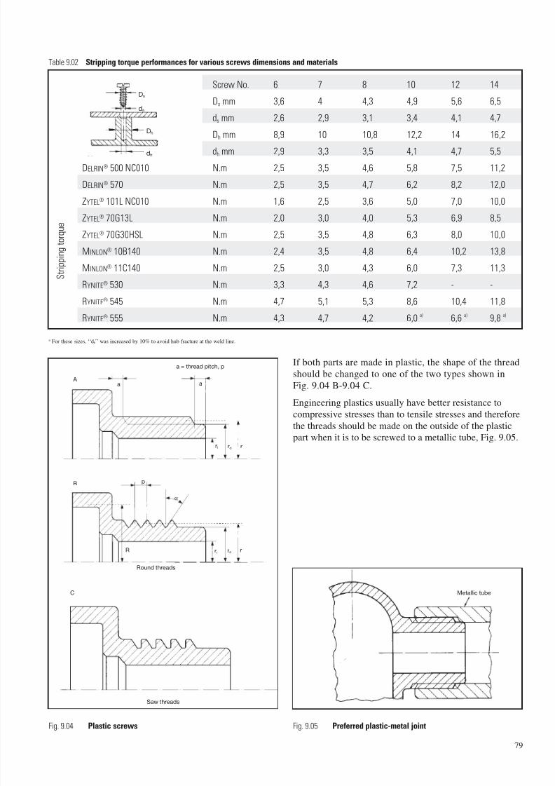
7/23/2019 f1236720 DuPont Engineering Polymers General Design Principles Module I
http://slidepdf.com/reader/full/f1236720-dupont-engineering-polymers-general-design-principles-module-i 81/155
If both parts are made in plastic, the shape of the thread
should be changed to one of the two types shown in
Fig. 9.04 B-9.04 C.
Engineering plastics usually have better resistance to
compressive stresses than to tensile stresses and thereforethe threads should be made on the outside of the plasticpart when it is to be screwed to a metallic tube, Fig. 9.05.
79
Screw No. 6 7 8 10 12 14
Ds mm 3,6 4 4,3 4,9 5,6 6,5
ds mm 2,6 2,9 3,1 3,4 4,1 4,7
Dh mm 8,9 10 10,8 12,2 14 16,2dh mm 2,9 3,3 3,5 4,1 4,7 5,5
DELRIN® 500 NC010 N.m 2,5 3,5 4,6 5,8 7,5 11,2
DELRIN® 570 N.m 2,5 3,5 4,7 6,2 8,2 12,0
ZYTEL® 101L NC010 N.m 1,6 2,5 3,6 5,0 7,0 10,0
ZYTEL® 70G13L N.m 2,0 3,0 4,0 5,3 6,9 8,5
ZYTEL® 70G30HSL N.m 2,5 3,5 4,8 6,3 8,0 10,0
MINLON® 10B140 N.m 2,4 3,5 4,8 6,4 10,2 13,8
MINLON® 11C140 N.m 2,5 3,0 4,3 6,0 7,3 11,3
RYNITE® 530 N.m 3,3 4,3 4,6 7,2 - -
RYNITE® 545 N.m 4,7 5,1 5,3 8,6 10,4 11,8
RYNITE® 555 N.m 4,3 4,7 4,2 6,0 a) 6,6 a) 9,8 a)
Table 9.02 Stripping torque performances for various screws dimensions and materials
S t r i p p i n g
t o r q u e
Ds
ds
Dh
dh
a For these sizes, ‘‘dh’’ was increased by 10% to avoid hub fracture at the weld line.
a a
ri ro r
A
Saw threads
a = thread pitch, p
p
R rI ro r
C
B
Round threads
Fig. 9.04 Plastic screws Fig. 9.05 Preferred plastic-metal joint
Metallic tube
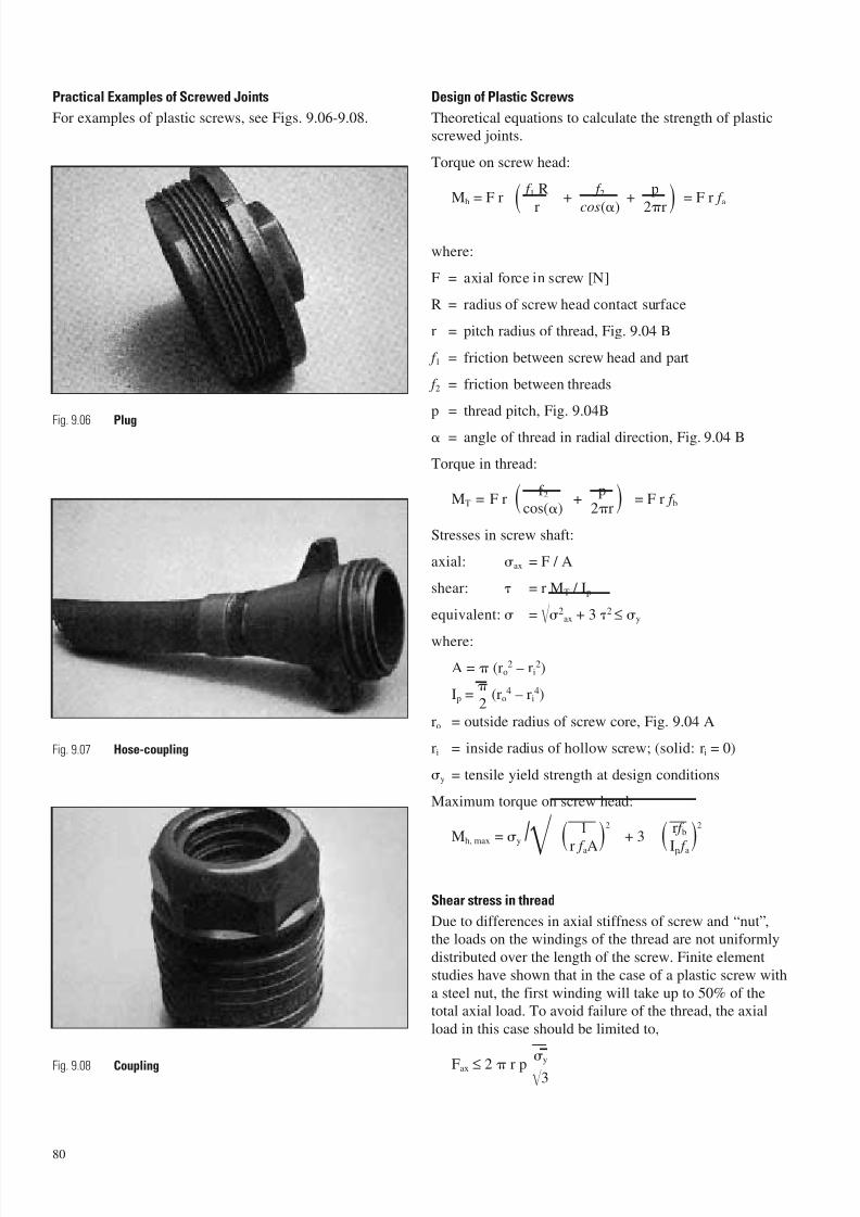
7/23/2019 f1236720 DuPont Engineering Polymers General Design Principles Module I
http://slidepdf.com/reader/full/f1236720-dupont-engineering-polymers-general-design-principles-module-i 82/155
Practical Examples of Screwed Joints
For examples of plastic screws, see Figs. 9.06-9.08.
Design of Plastic Screws
Theoretical equations to calculate the strength of plasticscrewed joints.
Torque on screw head:
Mh = F r f 1 R
+ f 2 +
p= F r f a
r cos() 2r
where:
F = axial force in screw [N]
R = radius of screw head contact surface
r = pitch radius of thread, Fig. 9.04 B
f 1 = friction between screw head and part
f 2 = friction between threads
p = thread pitch, Fig. 9.04B
= angle of thread in radial direction, Fig. 9.04 B
Torque in thread:
MT = F rf 2 +
p= F r f bcos() 2r
Stresses in screw shaft:
axial: ax = F / A
shear: = r MT / Ip
equivalent: = 2ax + 3 2
≤ y
where:
A = (ro2 – ri
2)
Ip =
(ro4 – ri
4)2
ro = outside radius of screw core, Fig. 9.04 A
ri = inside radius of hollow screw; (solid: ri = 0)
y = tensile yield strength at design conditions
Maximum torque on screw head:
Mh, max = y /
1+ 3
r f b
r f aA Ip f a
Shear stress in thread
Due to differences in axial stiffness of screw and “nut”,the loads on the windings of the thread are not uniformly
distributed over the length of the screw. Finite element
studies have shown that in the case of a plastic screw with
a steel nut, the first winding will take up to 50% of thetotal axial load. To avoid failure of the thread, the axial
load in this case should be limited to,
Fax ≤ 2 r py
3
80
Fig. 9.06 Plug
Fig. 9.07 Hose-coupling
Fig. 9.08 Coupling
2 2
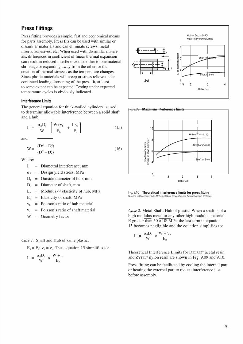
7/23/2019 f1236720 DuPont Engineering Polymers General Design Principles Module I
http://slidepdf.com/reader/full/f1236720-dupont-engineering-polymers-general-design-principles-module-i 83/155
Press Fittings
Press fitting provides a simple, fast and economical means
for parts assembly. Press fits can be used with similar or
dissimilar materials and can eliminate screws, metalinserts, adhesives, etc. When used with dissimilar materi-
als, differences in coefficient of linear thermal expansion
can result in reduced interference due either to one materialshrinkage or expanding away from the other, or thecreation of thermal stresses as the temperature changes.
Since plastic materials will creep or stress relieve under
continued loading, loosening of the press fit, at least
to some extent can be expected. Testing under expectedtemperature cycles is obviously indicated.
Interference Limits
The general equation for thick-walled cylinders is used
to determine allowable interference between a solid shaftand a hub:
I =dDs [ W+ νh
+l– νs ] (15)
W Eh Es
and
W=(Dh
2 + Ds2)
(16)(Dh
2 – Ds2)
Where:
I = Diametral interference, mm
d = Design yield stress, MPa
Dh = Outside diameter of hub, mmDs = Diameter of shaft, mm
Eh = Modulus of elasticity of hub, MPa
Es = Elasticity of shaft, MPa
νh = Poisson’s ratio of hub material
νs = Poisson’s ratio of shaft material
W = Geometry factor
Case 1. Shaft and Hub of same plastic.Eh = Es; νh = νs. Thus equation 15 simplifies to:
I =dDs ×
W + 1
W Eh
Fig. 9.09 Maximum interference limits
Fig. 9.10 Theoretical interference limits for press fittingBased on yield point and Elastic Modulus at Room Temperature and Average Moisture Conditions
Case 2. Metal Shaft; Hub of plastic. When a shaft is of a
high modulus metal or any other high modulus material,
E greater than 50 ×103 MPa, the last term in equation
15 becomes negligible and the equation simplifies to:
I =dDs ×
W + νh
W Eh
Theoretical Interference Limits for DELRIN® acetal resin
and ZYTEL® nylon resin are shown in Fig. 9.09 and 9.10.
Press fitting can be facilitated by cooling the internal part
or heating the external part to reduce interference just
before assembly.
81
4321,5
6
5
4d1
2·d
D
d
3
Shaft in Steel
Shaft in DELRIN®
Ratio D/ d
Hub of DELRIN® 500
Max. Interference Limits
% o
f i n s e r t d i a
m e t e r
1 2 3 4 5
4
2
6
8
10
Shaft of ZYTEL®
Shaft of Steel
Hub of ZYTEL® 101
Ratio D/d
I n t e r f e r e n c e l i m i t s
c m / c m o f s h a f t d i a m e t e r
d
d1
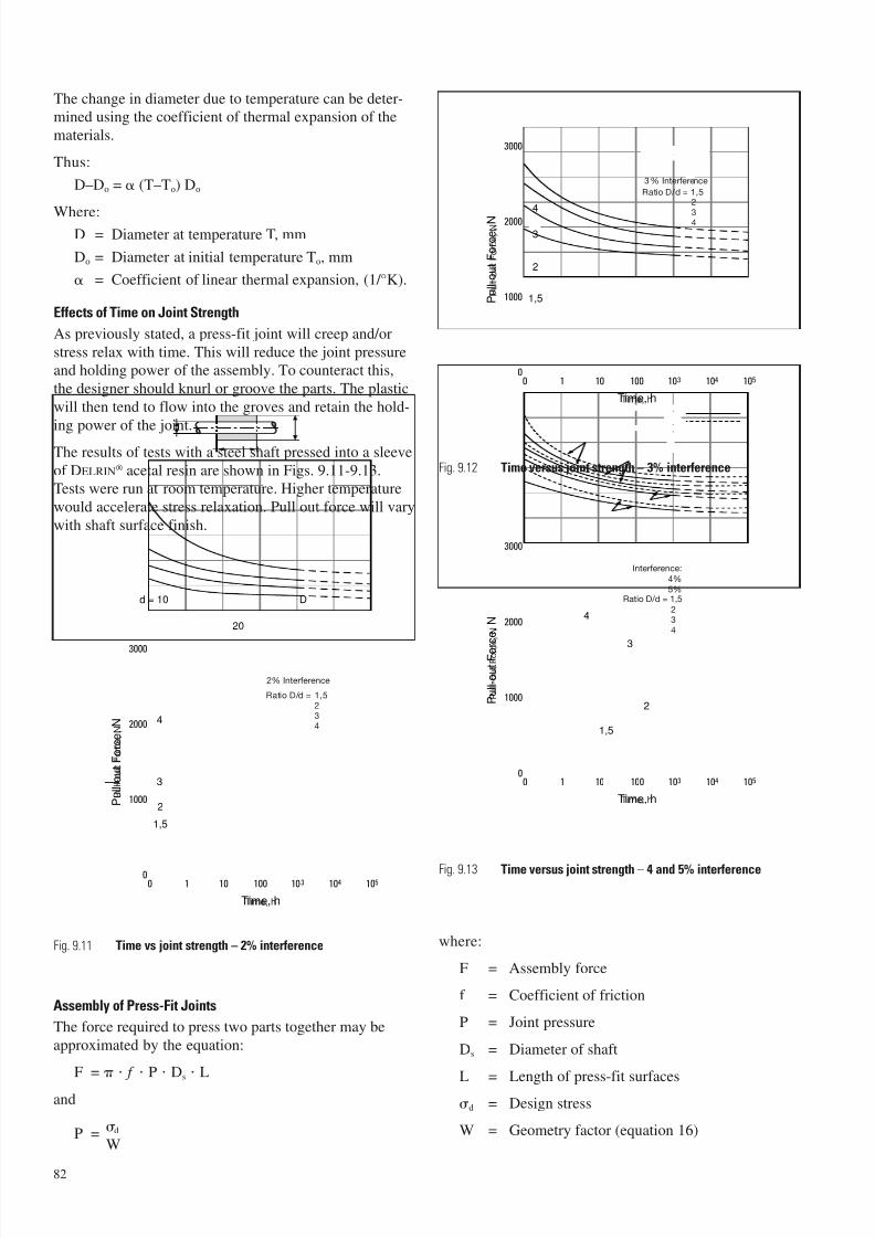
7/23/2019 f1236720 DuPont Engineering Polymers General Design Principles Module I
http://slidepdf.com/reader/full/f1236720-dupont-engineering-polymers-general-design-principles-module-i 84/155
The change in diameter due to temperature can be deter-mined using the coefficient of thermal expansion of the
materials.
Thus:
D–Do = (T–To) Do
Where:D = Diameter at temperature T, mm
Do = Diameter at initial temperature To, mm
= Coefficient of linear thermal expansion, (1/ °K).
Effects of Time on Joint Strength
As previously stated, a press-fit joint will creep and/or
stress relax with time. This will reduce the joint pressureand holding power of the assembly. To counteract this,
the designer should knurl or groove the parts. The plastic
will then tend to flow into the groves and retain the hold-
ing power of the joint.
The results of tests with a steel shaft pressed into a sleeve
of DELRIN® acetal resin are shown in Figs. 9.11-9.13.Tests were run at room temperature. Higher temperature
would accelerate stress relaxation. Pull out force will vary
with shaft surface finish.
Fig. 9.11 Time vs joint strength – 2% interference
Assembly of Press-Fit Joints
The force required to press two parts together may be
approximated by the equation:
F = • f • P • Ds • L
and
P =d
W
Fig. 9.12 Time versus joint strength – 3% interference
Fig. 9.13 Time versus joint strength – 4 and 5% interference
where:
F = Assembly force
f = Coefficient of friction
P = Joint pressure
Ds = Diameter of shaft
L = Length of press-fit surfaces
d = Design stress
W = Geometry factor (equation 16)
82
0 1 10 100 103 104 105
1000
4
3
2
1,5
0
2000
3000
20
Dd = 10
Time, h
P u l l - o u t F o r c e ,
N
2% Interference
Ratio D/d = 1,5
0 1
2
3
4
10 100 103 104 105
2000
3000
0
1000 1,5
Time, h
P u l l - o u t F o r c e , N
1000
0
2000
3000
0 1 10
3
2
1,5
4
100 103 104 105
Time, h
P u l l - o u t F o
r c e ,
N
3% Interference
Ratio D/d = 1,5
23
4
Interference:
234
2
34
4%
5%Ratio D/d = 1,5
P u l l - o u t F o r c e ,
N
P u l l - o u t F o r c e ,
N
P u l l - o u t F o r c e ,
N
Time, h
Time, h
Time, h
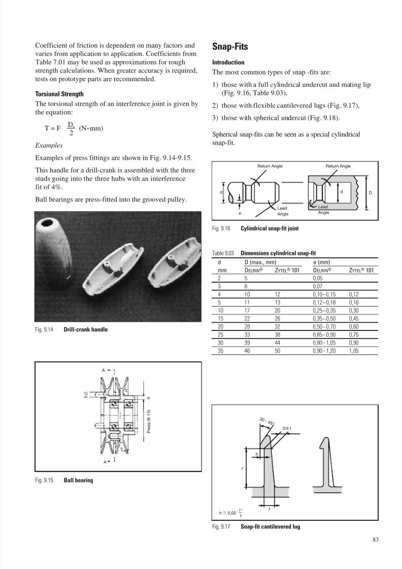
7/23/2019 f1236720 DuPont Engineering Polymers General Design Principles Module I
http://slidepdf.com/reader/full/f1236720-dupont-engineering-polymers-general-design-principles-module-i 85/155
Coefficient of friction is dependent on many factors andvaries from application to application. Coefficients from
Table 7.01 may be used as approximations for rough
strength calculations. When greater accuracy is required,
tests on prototype parts are recommended.
Torsional Strength
The torsional strength of an interference joint is given by
the equation:
T = FDs (N .mm)2
Examples
Examples of press fittings are shown in Fig. 9.14-9.15.
This handle for a drill-crank is assembled with the three
studs going into the three hubs with an interference
fit of 4%.
Ball bearings are press-fitted into the grooved pulley.
Fig. 9.14 Drill-crank handle
Fig. 9.15 Ball bearing
Snap-Fits
Introduction
The most common types of snap -fits are:
1) those with a full cylindrical undercut and mating lip(Fig. 9.16, Table 9.03),
2) those with flexible cantilevered lugs (Fig. 9.17),
3) those with spherical undercut (Fig. 9.18).
Spherical snap-fits can be seen as a special cylindricalsnap-fit.
Fig. 9.16 Cylindrical snap-fit joint
Table 9.03 Dimensions cylindrical snap-fit
d D (max., mm) e (mm)
mm DELRIN® ZYTEL® 101 DELRIN® ZYTEL® 101
2 5 0,05
3 8 0,07
4 10 12 0,10–0,15 0,12
5 11 13 0,12–0,18 0,16
10 17 20 0,25–0,35 0,30
15 22 26 0,35–0,50 0,45
20 28 32 0,50–0,70 0,60
25 33 38 0,65–0,90 0,75
30 39 44 0,80–1,05 0,90
35 46 50 0,90–1,20 1,05
A
A
3
5 ∅
P r e s s - f i t 1 %
4
2
d
eLead
Angle
Return Angle
d D
Return Angle
Lead
Angle
h
t
l
3 0 - 4 5 °
3/4 t
h 0,02· l 2
t
Fig. 9.17 Snap-fit cantilevered lug
83
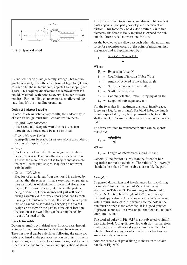
7/23/2019 f1236720 DuPont Engineering Polymers General Design Principles Module I
http://slidepdf.com/reader/full/f1236720-dupont-engineering-polymers-general-design-principles-module-i 86/155
Fig. 9.18 Spherical snap-fit
Cylindrical snap-fits are generally stronger, but require
greater assembly force than cantilevered lugs. In cylindri-
cal snap-fits, the undercut part is ejected by snapping off a core. This requires deformation for removal from the
mould. Materials with good recovery characteristics are
required. For moulding complex parts, cantilevered lugs
may simplify the moulding operation.
Design of Undercut Snap-Fits
In order to obtain satisfactory results, the undercut type
of snap-fit design must fulfill certain requirements:
– Uniform Wall Thickness
It is essential to keep the wall thickness constant
throughout. There should be no stress risers.
– Free to Move or Deflect
A snap-fit must be placed in an area where the undercutsection can expand freely.
– Shape
For this type of snap-fit, the ideal geometric shape
is a circular one. The more the shape deviates from
a circle, the more difficult it is to eject and assemblethe part. Rectangular shaped snap-fits do not work
satisfactorily.
– Gates – Weld Lines
Ejection of an undercut from the mould is assisted by
the fact that the resin is still at a very high temperature,
thus its modulus of elasticity is lower and elongationhigher. This is not the case, later, when the parts are
being assembled. Often an undercut part will crack
during assembly due to weak spots produced by weld
lines, gate turbulence, or voids. If a weld line is a prob-lem and cannot be avoided by changing the overall
design or by moving the gate to some other location,
the section at the weld line can be strengthened by
means of a bead or rib.
Force to Assemble
During assembly, cylindrical snap-fit parts pass througha stressed condition due to the designed interference.
The stress level can be calculated following the same pro-cedure outlined in the previous section on press fits. With
snap-fits, higher stress level and lower design safety factoris permissible due to the momentary application of stress.
The force required to assemble and disassemble snap-fitparts depends upon part geometry and coefficient of
friction. This force may be divided arbitrarily into two
elements: the force initially required to expand the hub,
and the force needed to overcome friction.
As the beveled edges slide past each other, the maximum
force for expansion occurs at the point of maximum hubexpansion and is approximated by:
Fe =[tan () + f ] d DsLh
W
Where:
Fe = Expansion force, N
f = Coefficient of friction (Table 7.01)
= Angle of beveled surface, lead angle
d = Stress due to interference, MPa
Ds
= Shaft diameter, mm
W = Geometry factor (Press-Fitting equation 16)
Lh = Length of hub expanded, mm
For the formulae for maximum diametral interference,
I, see eq. (15), (pressfittings). For blind hubs, the lengthof hub expanded Lh may be approximately by twice the
shaft diameter. Poisson’s ratio can be found in the product
data.
The force required to overcome friction can be approxi-
mated by:
Ff = f
dDsLs
W
Where:
Ls = Length of interference sliding surface
Generally, the friction is less than the force for hub
expansion for most assemblies. The value of [γ + atan (f)]
should be less than 90° to be able to assemble the parts.
Examples
Suggested dimensions and interferences for snap-fitting
a steel shaft into a blind hub of ZYTEL® nylon resinare given in Table 9.03. Terminology is illustrated in
Fig. 9.16. A return bevel angle of 45° is satisfactory
for most applications. A permanent joint can be achievedwith a return angle of 90° in which case the hole in the
hub must be open at the other end. It is a good practice
to provide a 30° lead-in bevel on the shaft end to facilitate
entry into the hub.
The toothed pulley in Fig. 9.19 is not subjected to signifi-
cant axial load. A snap-fit provided with slots is, therefore,quite adequate. It allows a deeper groove and, therefore,
a higher thrust bearing shoulder, which is advantageoussince it is subject to wear.
Another example of press fitting is shown in the brake
handle of Fig. 9.20.
84
dF
e
c
D
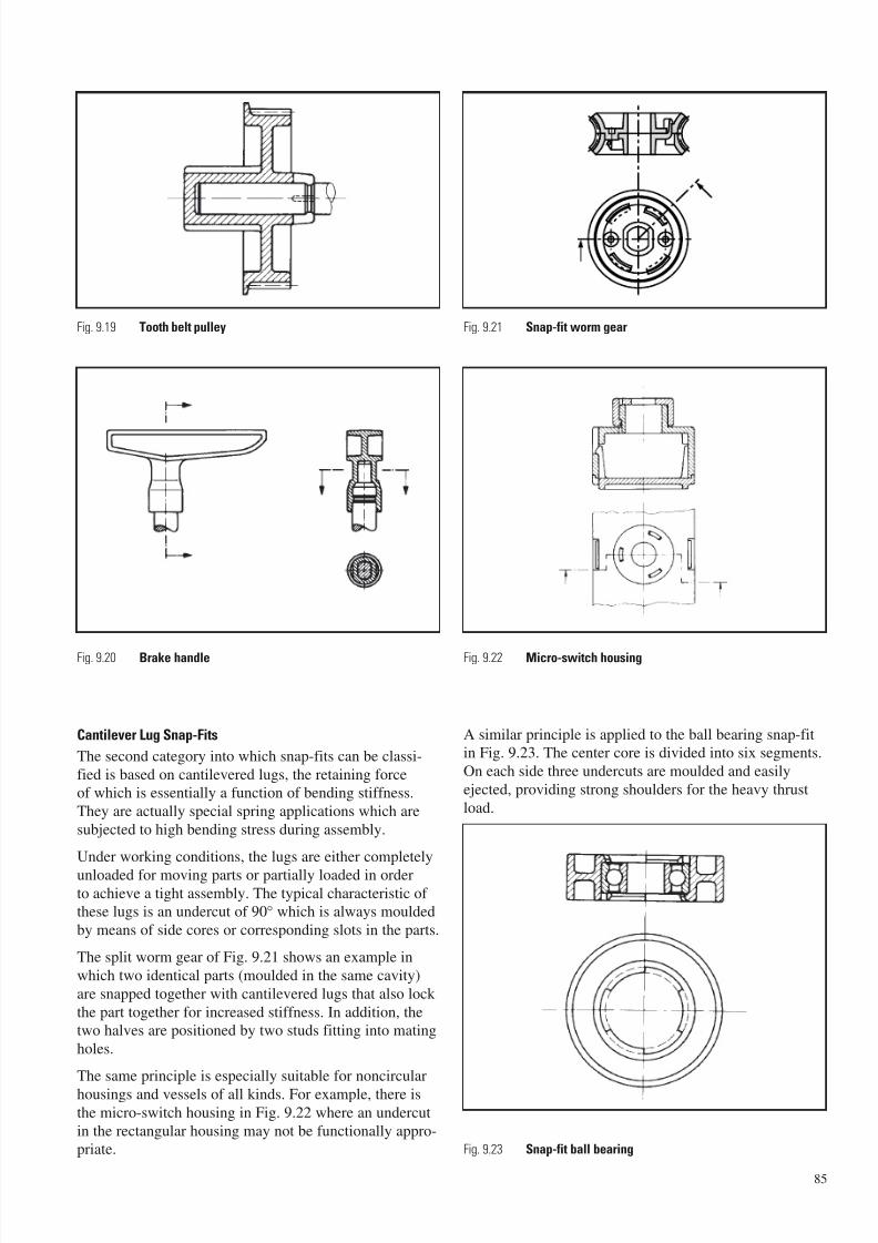
7/23/2019 f1236720 DuPont Engineering Polymers General Design Principles Module I
http://slidepdf.com/reader/full/f1236720-dupont-engineering-polymers-general-design-principles-module-i 87/155
Cantilever Lug Snap-Fits
The second category into which snap-fits can be classi-
fied is based on cantilevered lugs, the retaining forceof which is essentially a function of bending stiffness.
They are actually special spring applications which are
subjected to high bending stress during assembly.
Under working conditions, the lugs are either completely
unloaded for moving parts or partially loaded in orderto achieve a tight assembly. The typical characteristic of these lugs is an undercut of 90° which is always moulded
by means of side cores or corresponding slots in the parts.
The split worm gear of Fig. 9.21 shows an example in
which two identical parts (moulded in the same cavity)
are snapped together with cantilevered lugs that also lock
the part together for increased stiffness. In addition, thetwo halves are positioned by two studs fitting into mating
holes.
The same principle is especially suitable for noncircular
housings and vessels of all kinds. For example, there isthe micro-switch housing in Fig. 9.22 where an undercut
in the rectangular housing may not be functionally appro-priate.
A similar principle is applied to the ball bearing snap-fitin Fig. 9.23. The center core is divided into six segments.
On each side three undercuts are moulded and easily
ejected, providing strong shoulders for the heavy thrust
load.
85
Fig. 9.23 Snap-fit ball bearing
Fig. 9.19 Tooth belt pulley
Fig. 9.20 Brake handle
Fig. 9.21 Snap-fit worm gear
Fig. 9.22 Micro-switch housing
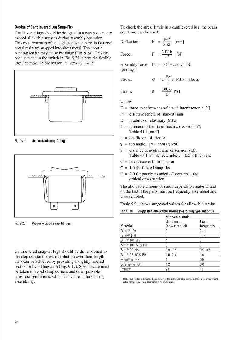
7/23/2019 f1236720 DuPont Engineering Polymers General Design Principles Module I
http://slidepdf.com/reader/full/f1236720-dupont-engineering-polymers-general-design-principles-module-i 88/155
86
Design of Cantilevered Lug Snap-Fits
Cantilevered lugs should be designed in a way so as not toexceed allowable stresses during assembly operation.
This requirement is often neglected when parts in DELRIN®
acetal resin are snapped into sheet metal. Too short a
bending length may cause breakage (Fig. 9.24). This has
been avoided in the switch in Fig. 9.25, where the flexiblelugs are considerably longer and stresses lower.
Fig. 9.24 Undersized snap-fit lugs
Fig. 9.25 Properly sized snap-fit lugs
Cantilevered snap-fit lugs should be dimensioned to
develop constant stress distribution over their length.This can be achieved by providing a slightly tapered
section or by adding a rib (Fig. 9.17). Special care must
be taken to avoid sharp corners and other possible
stress concentrations, which can cause failure duringassembling.
To check the stress levels in a cantilevered lug, the beamequations can be used:
Deflection: h =Fl 3
[mm]3 EI
Force: F =3 EI h
[N]l 3
Assembly force Fa = F (f + tan ) [N]
(per lug):
Stress: σ = CFl
y [MPa] (elastic)I
Strain: ε =100
[%]E
where:
F = force to deform snap-fit with interference h [N]
l = effective length of snap-fit [mm]
E = modulus of elasticity [MPa]
I = moment of inertia of mean cross section1),
Table 4.01 [mm4]
f = coefficient of friction
γ = top angle, [ + atan ( f )]<90
y = distance to neutral axis on tension side,Table 4.01 [mm]; rectangle: y = 0,5 × thickness
C = stress concentration factor
C = 1,0 for filleted snap-fits
C = 2,0 for poorly rounded off corners at the
critical cross section
The allowable amount of strain depends on material andon the fact if the parts must be frequently assembled and
disassembled.
Table 9.04 shows suggested values for allowable strains.
Table 9.04 Suggested allowable strains (%) for lug type snap-fits
Allowable strain
Used once UsedMaterial (new material) frequently
DELRIN® 100 8 2–4
DELRIN® 500 6 2–3
ZYTEL® 101, dry 4 2
ZYTEL® 101, 50% RH 6 3
ZYTEL® GR, dry 0,8–1,2 0,5–0,7
ZYTEL® GR, 50% RH 1,5–2,0 1,0
RYNITE® PET GR 1 0,5
CRASTIN® PBT GR 1,2 0,6
HYTREL® 20 10
1) If the snap-fit lug is tapered, the accuracy of the beam formulae drops. In that case a more compli-
cated model (e.g. Finite Elements) is recommended.
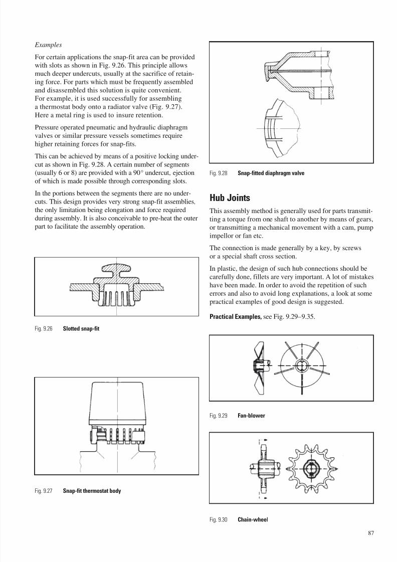
7/23/2019 f1236720 DuPont Engineering Polymers General Design Principles Module I
http://slidepdf.com/reader/full/f1236720-dupont-engineering-polymers-general-design-principles-module-i 89/155
Examples
For certain applications the snap-fit area can be providedwith slots as shown in Fig. 9.26. This principle allows
much deeper undercuts, usually at the sacrifice of retain-
ing force. For parts which must be frequently assembled
and disassembled this solution is quite convenient.
For example, it is used successfully for assemblinga thermostat body onto a radiator valve (Fig. 9.27).
Here a metal ring is used to insure retention.
Pressure operated pneumatic and hydraulic diaphragm
valves or similar pressure vessels sometimes require
higher retaining forces for snap-fits.
This can be achieved by means of a positive locking under-
cut as shown in Fig. 9.28. A certain number of segments(usually 6 or 8) are provided with a 90° undercut, ejection
of which is made possible through corresponding slots.
In the portions between the segments there are no under-cuts. This design provides very strong snap-fit assemblies,
the only limitation being elongation and force required
during assembly. It is also conceivable to pre-heat the outerpart to facilitate the assembly operation.
Hub JointsThis assembly method is generally used for parts transmit-
ting a torque from one shaft to another by means of gears,or transmitting a mechanical movement with a cam, pump
impellor or fan etc.
The connection is made generally by a key, by screws
or a special shaft cross section.
In plastic, the design of such hub connections should be
carefully done, fillets are very important. A lot of mistakes
have been made. In order to avoid the repetition of such
errors and also to avoid long explanations, a look at somepractical examples of good design is suggested.
Practical Examples, see Fig. 9.29–9.35.
87
Fig. 9.26 Slotted snap-fit
Fig. 9.29 Fan-blower
Fig. 9.30 Chain-wheel
Fig. 9.28 Snap-fitted diaphragm valve
Fig. 9.27 Snap-fit thermostat body
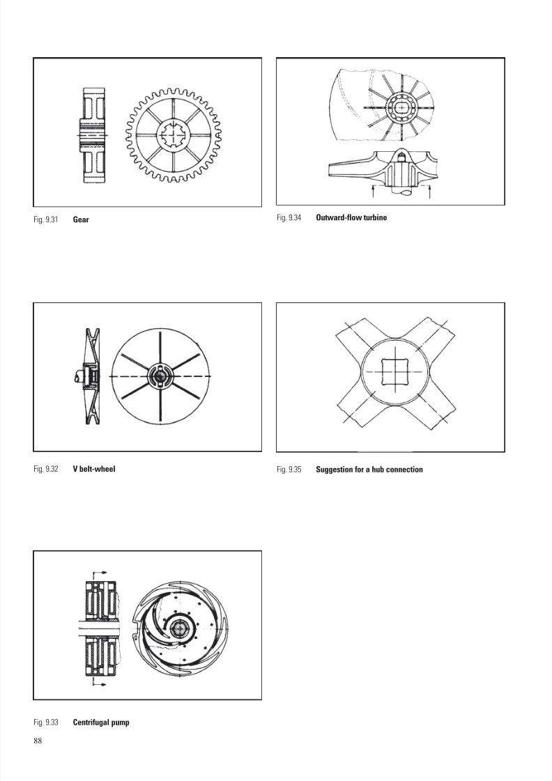
7/23/2019 f1236720 DuPont Engineering Polymers General Design Principles Module I
http://slidepdf.com/reader/full/f1236720-dupont-engineering-polymers-general-design-principles-module-i 90/155
88
Fig. 9.31 Gear
Fig. 9.32 V belt-wheel Fig. 9.35 Suggestion for a hub connection
Fig. 9.33 Centrifugal pump
Fig. 9.34 Outward-flow turbine
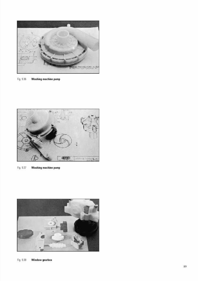
7/23/2019 f1236720 DuPont Engineering Polymers General Design Principles Module I
http://slidepdf.com/reader/full/f1236720-dupont-engineering-polymers-general-design-principles-module-i 91/155
89
Fig. 9.36 Washing machine pump
Fig. 9.37 Washing machine pump
Fig. 9.38 Window gearbox

7/23/2019 f1236720 DuPont Engineering Polymers General Design Principles Module I
http://slidepdf.com/reader/full/f1236720-dupont-engineering-polymers-general-design-principles-module-i 92/155
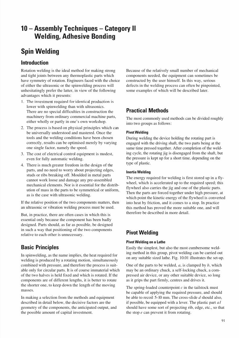
7/23/2019 f1236720 DuPont Engineering Polymers General Design Principles Module I
http://slidepdf.com/reader/full/f1236720-dupont-engineering-polymers-general-design-principles-module-i 93/155
Spin Welding
Introduction
Rotation welding is the ideal method for making strong
and tight joints between any thermoplastic parts which
have symmetry of rotation. Engineers faced with the choice
of either the ultrasonic or the spinwelding process will
unhesitatingly prefer the latter, in view of the following
advantages which it presents:
1. The investment required for identical production is
lower with spinwelding than with ultrasonics.
There are no special difficulties in construction the
machinery from ordinary commercial machine parts,either wholly or partly in one’s own workshop.
2. The process is based on physical principles which can
be universally understood and mastered. Once the
tools and the welding conditions have been chosen
correctly, results can be optimised merely by varying
one single factor, namely the speed.
3. The cost of electrical control equipment is modest,
even for fully automatic welding.
4. There is much greater freedom in the design of the
parts, and no need to worry about projecting edges,
studs or ribs breaking off. Moulded in metal parts
cannot work loose and damage any pre-assembled
mechanical elements. Nor is it essential for the distrib-
ution of mass in the parts to be symmetrical or uniform,
as is the case with ultrasonic welding.
If the relative position of the two components matters, then
an ultrasonic or vibration welding process must be used.
But, in practice, there are often cases in which this is
essential only because the component has been badly
designed. Parts should, as far as possible, be designed
in such a way that positioning of the two components
relative to each other is unnecessary.
Basic Principles
In spinwelding, as the name implies, the heat required forwelding is produced by a rotating motion, simultaneously
combined with pressure, and therefore the process is suit-
able only for circular parts. It is of course immaterial which
of the two halves is held fixed and which is rotated. If thecomponents are of different lengths, it is better to rotate
the shorter one, to keep down the length of the moving
masses.
In making a selection from the methods and equipmentdescribed in detail below, the decisive factors are the
geometry of the components, the anticipated output, andthe possible amount of capital investment.
Because of the relatively small number of mechanical
components needed, the equipment can sometimes be
constructed by the user himself. In this way, seriousdefects in the welding process can often be pinpointed,
some examples of which will be described later.
Practical Methods
The most commonly used methods can be divided roughlyinto two groups as follows:
Pivot Welding
During welding the device holding the rotating part is
engaged with the driving shaft, the two parts being at thesame time pressed together. After completion of the weld-
ing cycle, the rotating jig is disengaged from the shaft, but
the pressure is kept up for a short time, depending on the
type of plastic.
Inertia Welding
The energy required for welding is first stored up in a fly-wheel, which is accelerated up to the required speed; this
flywheel also carries the jig and one of the plastic parts.Then the parts are forced together under high pressure, at
which point the kinetic energy of the flywheel is converted
into heat by friction, and it comes to a stop. In practice
this method has proved the more suitable one, and willtherefore be described in more detail.
Pivot Welding
Pivot Welding on a Lathe
Easily the simplest, but also the most cumbersome weld-ing method in this group, pivot welding can be carried out
on any suitable sized lathe. Fig. 10.01 illustrates the set-up.
One of the parts to be welded, a, is clamped by b, which
may be an ordinary chuck, a self-locking chuck, a com-
pressed air device, or any other suitable device, so longas it grips the part firmly, centres and drives it.
The spring-loaded counterpoint c in the tailstock mustbe capable of applying the required pressure, and should
be able to recoil 5-10 mm. The cross-slide d should also,if possible, be equipped with a lever. The plastic part a1
should have some sort of projecting rib, edge, etc., so thatthe stop e can prevent it from rotating.
91
10 – Assembly Techniques – Category II Welding, Adhesive Bonding
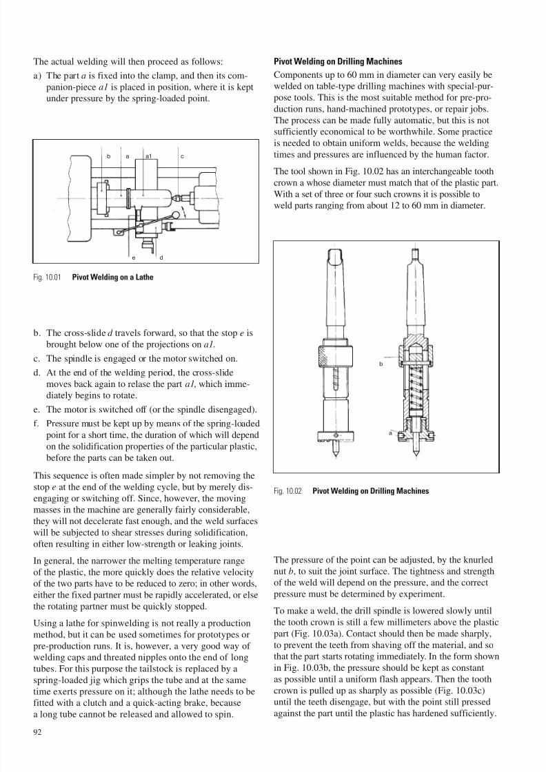
7/23/2019 f1236720 DuPont Engineering Polymers General Design Principles Module I
http://slidepdf.com/reader/full/f1236720-dupont-engineering-polymers-general-design-principles-module-i 94/155
The actual welding will then proceed as follows:
a) The part a is fixed into the clamp, and then its com-
panion-piece a1 is placed in position, where it is keptunder pressure by the spring-loaded point.
b. The cross-slide d travels forward, so that the stop e is
brought below one of the projections on a1.
c. The spindle is engaged or the motor switched on.
d. At the end of the welding period, the cross-slide
moves back again to relase the part a1, which imme-diately begins to rotate.
e. The motor is switched off (or the spindle disengaged).
f. Pressure must be kept up by means of the spring-loaded
point for a short time, the duration of which will depend
on the solidification properties of the particular plastic,
before the parts can be taken out.
This sequence is often made simpler by not removing the
stop e at the end of the welding cycle, but by merely dis-
engaging or switching off. Since, however, the movingmasses in the machine are generally fairly considerable,
they will not decelerate fast enough, and the weld surfaces
will be subjected to shear stresses during solidification,
often resulting in either low-strength or leaking joints.
In general, the narrower the melting temperature range
of the plastic, the more quickly does the relative velocityof the two parts have to be reduced to zero; in other words,
either the fixed partner must be rapidly accelerated, or else
the rotating partner must be quickly stopped.
Using a lathe for spinwelding is not really a production
method, but it can be used sometimes for prototypes or
pre-production runs. It is, however, a very good way of welding caps and threated nipples onto the end of long
tubes. For this purpose the tailstock is replaced by a
spring-loaded jig which grips the tube and at the sametime exerts pressure on it; although the lathe needs to befitted with a clutch and a quick-acting brake, because
a long tube cannot be released and allowed to spin.
Pivot Welding on Drilling Machines
Components up to 60 mm in diameter can very easily bewelded on table-type drilling machines with special-pur-
pose tools. This is the most suitable method for pre-pro-
duction runs, hand-machined prototypes, or repair jobs.
The process can be made fully automatic, but this is not
sufficiently economical to be worthwhile. Some practiceis needed to obtain uniform welds, because the welding
times and pressures are influenced by the human factor.
The tool shown in Fig. 10.02 has an interchangeable tooth
crown a whose diameter must match that of the plastic part.
With a set of three or four such crowns it is possible toweld parts ranging from about 12 to 60 mm in diameter.
The pressure of the point can be adjusted, by the knurled
nut b, to suit the joint surface. The tightness and strengthof the weld will depend on the pressure, and the correct
pressure must be determined by experiment.
To make a weld, the drill spindle is lowered slowly until
the tooth crown is still a few millimeters above the plastic
part (Fig. 10.03a). Contact should then be made sharply,
to prevent the teeth from shaving off the material, and sothat the part starts rotating immediately. In the form shown
in Fig. 10.03b, the pressure should be kept as constant
as possible until a uniform flash appears. Then the toothcrown is pulled up as sharply as possible (Fig. 10.03c)until the teeth disengage, but with the point still pressed
against the part until the plastic has hardened sufficiently.
92
ab a1 c
de
Fig. 10.01 Pivot Welding on a Lathe
Fig. 10.02 Pivot Welding on Drilling Machines
b
a
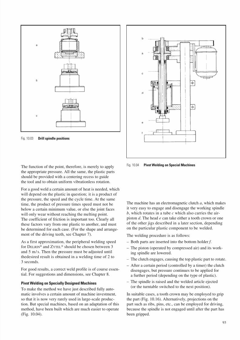
7/23/2019 f1236720 DuPont Engineering Polymers General Design Principles Module I
http://slidepdf.com/reader/full/f1236720-dupont-engineering-polymers-general-design-principles-module-i 95/155
The function of the point, therefore, is merely to apply
the appropriate pressure. All the same, the plastic parts
should be provided with a centering recess to guidethe tool and to obtain uniform vibrationless rotation.
For a good weld a certain amount of heat is needed, which
will depend on the plastic in question; it is a product of the pressure, the speed and the cycle time. At the same
time, the product of pressure times speed must not be
below a certain minimum value, or else the joint faces
will only wear without reaching the melting point.The coefficient of friction is important too. Clearly all
these factors vary from one plastic to another, and must
be determined for each case. (For the shape and arrange-
ment of the driving teeth, see Chapter 7).
As a first approximation, the peripheral welding speedfor DELRIN® and ZYTEL® should be chosen between 3
and 5 m/ s. Then the pressure must be adjusted until
thedesired result is obtained in a welding time of 2 to
3 seconds.
For good results, a correct weld profile is of course essen-
tial. For suggestions and dimensions, see Chapter 8.
Pivot Welding on Specially Designed Machines
To make the method we have just described fully auto-
matic involves a certain amount of machine investment,
so that it is now very rarely used in large-scale produc-tion. But special machines, based on an adaptation of this
method, have been built which are much easier to operate
(Fig. 10.04).
The machine has an electromagnetic clutch a, which makes
it very easy to engage and disengage the working spindleb, which rotates in a tube c which also carries the air-
piston d . The head e can take either a tooth crown or oneof the other jigs described in a later section, depending
on the particular plastic component to be welded.
The welding procedure is as follows:
– Both parts are inserted into the bottom holder f .
– The piston (operated by compressed air) and its work-
ing spindle are lowered.
– The clutch engages, causing the top plastic part to rotate.
– After a certain period (controlled by a timer) the clutch
disengages, but pressure continues to be applied fora further period (depending on the type of plastic).
– The spindle is raised and the welded article ejected
(or the turntable switched to the next position).
In suitable cases, a tooth crown may be employed to grip
the part (Fig. 10.16). Alternatively, projections on thepart such as ribs, pins, etc., can be employed for driving,
because the spindle is not engaged until after the part has
been gripped.
93
Fig. 10.03 Drill spindle positions
Fig. 10.04 Pivot Welding on Special Machines
a
b
c
b
a
c
d
e
f
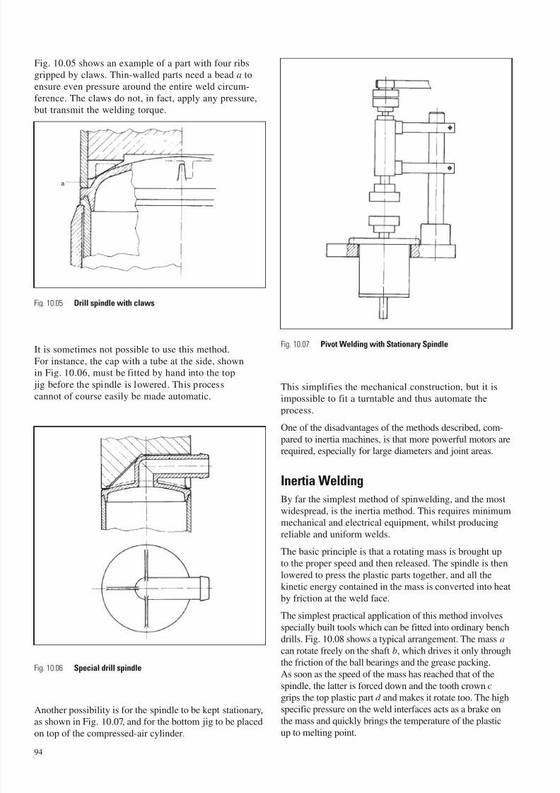
7/23/2019 f1236720 DuPont Engineering Polymers General Design Principles Module I
http://slidepdf.com/reader/full/f1236720-dupont-engineering-polymers-general-design-principles-module-i 96/155
Fig. 10.05 shows an example of a part with four ribsgripped by claws. Thin-walled parts need a bead a to
ensure even pressure around the entire weld circum-
ference. The claws do not, in fact, apply any pressure,but transmit the welding torque.
It is sometimes not possible to use this method.
For instance, the cap with a tube at the side, shownin Fig. 10.06, must be fitted by hand into the top
jig before the spindle is lowered. This process
cannot of course easily be made automatic.
Another possibility is for the spindle to be kept stationary,as shown in Fig. 10.07, and for the bottom jig to be placed
on top of the compressed-air cylinder.
This simplifies the mechanical construction, but it is
impossible to fit a turntable and thus automate the
process.
One of the disadvantages of the methods described, com-
pared to inertia machines, is that more powerful motors arerequired, especially for large diameters and joint areas.
Inertia Welding
By far the simplest method of spinwelding, and the most
widespread, is the inertia method. This requires minimummechanical and electrical equipment, whilst producing
reliable and uniform welds.
The basic principle is that a rotating mass is brought upto the proper speed and then released. The spindle is then
lowered to press the plastic parts together, and all thekinetic energy contained in the mass is converted into heat
by friction at the weld face.
The simplest practical application of this method involves
specially built tools which can be fitted into ordinary bench
drills. Fig. 10.08 shows a typical arrangement. The mass a
can rotate freely on the shaft b, which drives it only throughthe friction of the ball bearings and the grease packing.
As soon as the speed of the mass has reached that of the
spindle, the latter is forced down and the tooth crown c
grips the top plastic part d and makes it rotate too. The highspecific pressure on the weld interfaces acts as a brake on
the mass and quickly brings the temperature of the plastic
up to melting point.
94
a
Fig. 10.05 Drill spindle with claws
Fig. 10.06 Special drill spindle
Fig. 10.07 Pivot Welding with Stationary Spindle
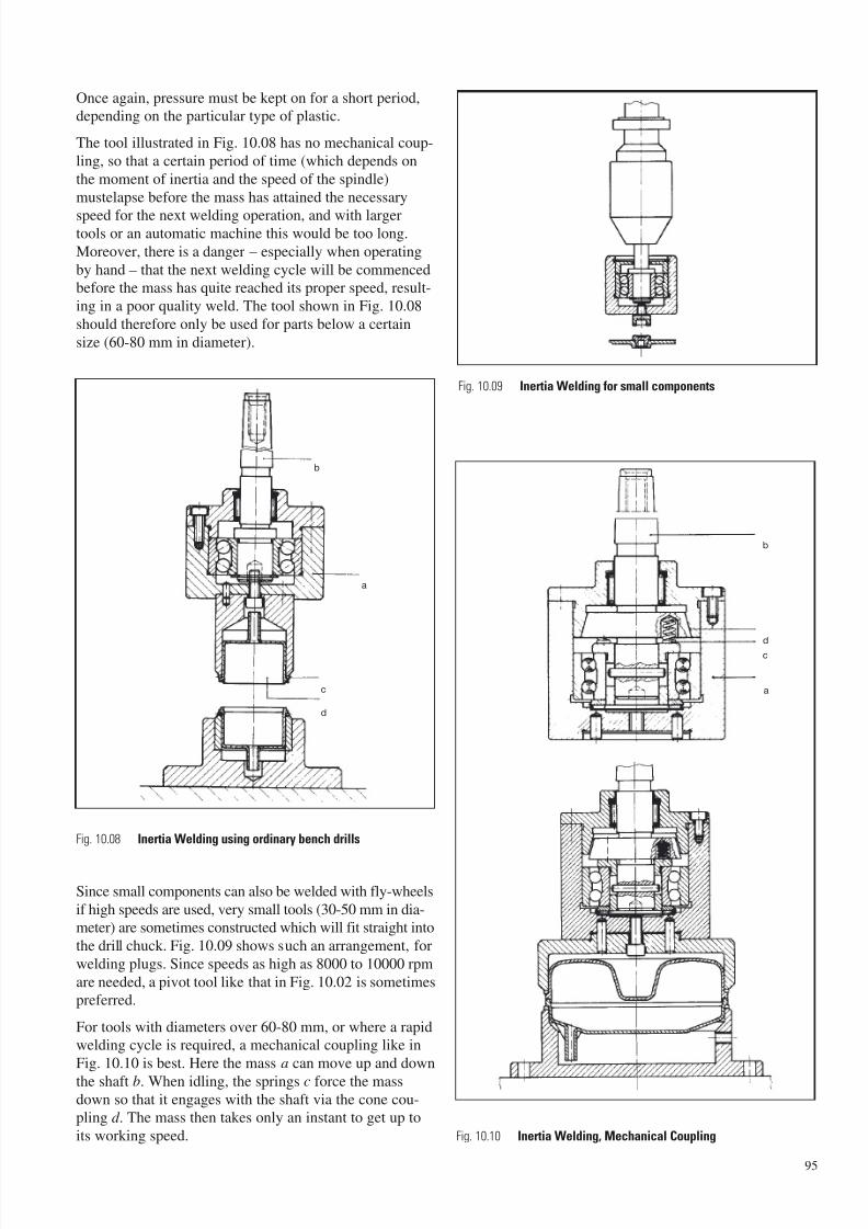
7/23/2019 f1236720 DuPont Engineering Polymers General Design Principles Module I
http://slidepdf.com/reader/full/f1236720-dupont-engineering-polymers-general-design-principles-module-i 97/155
Once again, pressure must be kept on for a short period,depending on the particular type of plastic.
The tool illustrated in Fig. 10.08 has no mechanical coup-
ling, so that a certain period of time (which depends on
the moment of inertia and the speed of the spindle)
mustelapse before the mass has attained the necessary
speed for the next welding operation, and with largertools or an automatic machine this would be too long.
Moreover, there is a danger – especially when operating
by hand – that the next welding cycle will be commencedbefore the mass has quite reached its proper speed, result-
ing in a poor quality weld. The tool shown in Fig. 10.08
should therefore only be used for parts below a certain
size (60-80 mm in diameter).
Since small components can also be welded with fly-wheels
if high speeds are used, very small tools (30-50 mm in dia-meter) are sometimes constructed which will fit straight into
the drill chuck. Fig. 10.09 shows such an arrangement, for
welding plugs. Since speeds as high as 8000 to 10000 rpm
are needed, a pivot tool like that in Fig. 10.02 is sometimespreferred.
For tools with diameters over 60-80 mm, or where a rapidwelding cycle is required, a mechanical coupling like in
Fig. 10.10 is best. Here the mass a can move up and down
the shaft b. When idling, the springs c force the massdown so that it engages with the shaft via the cone cou-pling d . The mass then takes only an instant to get up to
its working speed.
95
Fig. 10.08 Inertia Welding using ordinary bench drills
Fig. 10.09 Inertia Welding for small components
b
a
c
d
Fig. 10.10 Inertia Welding, Mechanical Coupling
b
d
a
c
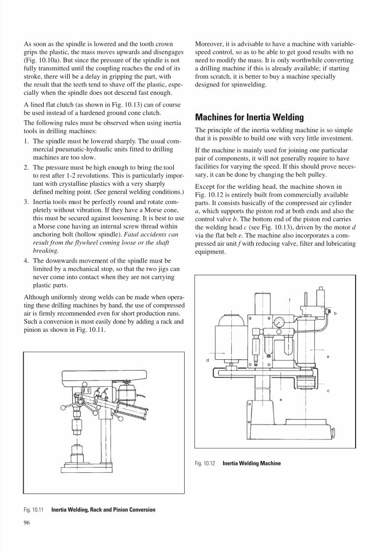
7/23/2019 f1236720 DuPont Engineering Polymers General Design Principles Module I
http://slidepdf.com/reader/full/f1236720-dupont-engineering-polymers-general-design-principles-module-i 98/155
As soon as the spindle is lowered and the tooth crowngrips the plastic, the mass moves upwards and disengages
(Fig. 10.10a). But since the pressure of the spindle is not
fully transmitted until the coupling reaches the end of its
stroke, there will be a delay in gripping the part, withthe result that the teeth tend to shave off the plastic, espe-
cially when the spindle does not descend fast enough.
A lined flat clutch (as shown in Fig. 10.13) can of course
be used instead of a hardened ground cone clutch.
The following rules must be observed when using inertia
tools in drilling machines:
1. The spindle must be lowered sharply. The usual com-mercial pneumatic-hydraulic units fitted to drilling
machines are too slow.
2. The pressure must be high enough to bring the toolto rest after 1-2 revolutions. This is particularly impor-
tant with crystalline plastics with a very sharply
defined melting point. (See general welding conditions.)3. Inertia tools must be perfectly round and rotate com-
pletely without vibration. If they have a Morse cone,
this must be secured against loosening. It is best to use
a Morse cone having an internal screw thread withinanchoring bolt (hollow spindle). Fatal accidents can
result from the flywheel coming loose or the shaft
breaking.
4. The downwards movement of the spindle must be
limited by a mechanical stop, so that the two jigs can
never come into contact when they are not carrying
plastic parts.
Although uniformly strong welds can be made when opera-
ting these drilling machines by hand, the use of compressedair is firmly recommended even for short production runs.
Such a conversion is most easily done by adding a rack and
pinion as shown in Fig. 10.11.
Moreover, it is advisable to have a machine with variable-speed control, so as to be able to get good results with no
need to modify the mass. It is only worthwhile converting
a drilling machine if this is already available; if starting
from scratch, it is better to buy a machine speciallydesigned for spinwelding.
Machines for Inertia Welding
The principle of the inertia welding machine is so simple
that it is possible to build one with very little investment.
If the machine is mainly used for joining one particular
pair of components, it will not generally require to havefacilities for varying the speed. If this should prove neces-
sary, it can be done by changing the belt pulley.
Except for the welding head, the machine shown in
Fig. 10.12 is entirely built from commercially availableparts. It consists basically of the compressed air cylindera, which supports the piston rod at both ends and also thecontrol valve b. The bottom end of the piston rod carries
the welding head c (see Fig. 10.13), driven by the motor d
via the flat belt e. The machine also incorporates a com-
pressed air unit f with reducing valve, filter and lubricatingequipment.
96
Fig. 10.11 Inertia Welding, Rack and Pinion Conversion
a
b
c
d
e
f
Fig. 10.12 Inertia Welding Machine
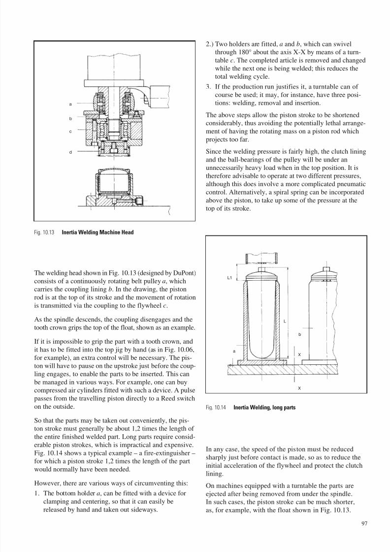
7/23/2019 f1236720 DuPont Engineering Polymers General Design Principles Module I
http://slidepdf.com/reader/full/f1236720-dupont-engineering-polymers-general-design-principles-module-i 99/155
The welding head shown in Fig. 10.13 (designed by DuPont)
consists of a continuously rotating belt pulley a, which
carries the coupling lining b. In the drawing, the pistonrod is at the top of its stroke and the movement of rotation
is transmitted via the coupling to the flywheel c.
As the spindle descends, the coupling disengages and thetooth crown grips the top of the float, shown as an example.
If it is impossible to grip the part with a tooth crown, and
it has to be fitted into the top jig by hand (as in Fig. 10.06,
for example), an extra control will be necessary. The pis-ton will have to pause on the upstroke just before the coup-
ling engages, to enable the parts to be inserted. This can
be managed in various ways. For example, one can buycompressed air cylinders fitted with such a device. A pulse
passes from the travelling piston directly to a Reed switch
on the outside.
So that the parts may be taken out conveniently, the pis-ton stroke must generally be about 1,2 times the length of
the entire finished welded part. Long parts require consid-
erable piston strokes, which is impractical and expensive.
Fig. 10.14 shows a typical example – a fire-extinguisher –
for which a piston stroke 1,2 times the length of the part
would normally have been needed.
However, there are various ways of circumventing this:1. The bottom holder a, can be fitted with a device for
clamping and centering, so that it can easily be
released by hand and taken out sideways.
2.) Two holders are fitted, a and b, which can swivelthrough 180° about the axis X-X by means of a turn-
table c. The completed article is removed and changed
while the next one is being welded; this reduces thetotal welding cycle.
3. If the production run justifies it, a turntable can of
course be used; it may, for instance, have three posi-tions: welding, removal and insertion.
The above steps allow the piston stroke to be shortenedconsiderably, thus avoiding the potentially lethal arrange-
ment of having the rotating mass on a piston rod which
projects too far.
Since the welding pressure is fairly high, the clutch lining
and the ball-bearings of the pulley will be under an
unnecessarily heavy load when in the top position. It istherefore advisable to operate at two different pressures,
although this does involve a more complicated pneumatic
control. Alternatively, a spiral spring can be incorporatedabove the piston, to take up some of the pressure at thetop of its stroke.
In any case, the speed of the piston must be reduced
sharply just before contact is made, so as to reduce the
initial acceleration of the flywheel and protect the clutch
lining.
On machines equipped with a turntable the parts areejected after being removed from under the spindle.In such cases, the piston stroke can be much shorter,
as, for example, with the float shown in Fig. 10.13.
97
Fig. 10.13 Inertia Welding Machine Head
Fig. 10.14 Inertia Welding, long parts
a
b
c
d
L1
a
c
L
b
X
X
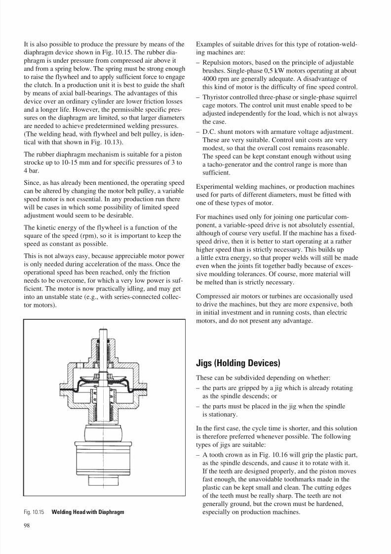
7/23/2019 f1236720 DuPont Engineering Polymers General Design Principles Module I
http://slidepdf.com/reader/full/f1236720-dupont-engineering-polymers-general-design-principles-module-i 100/155
It is also possible to produce the pressure by means of thediaphragm device shown in Fig. 10.15. The rubber dia-
phragm is under pressure from compressed air above it
and from a spring below. The spring must be strong enough
to raise the flywheel and to apply sufficient force to engagethe clutch. In a production unit it is best to guide the shaft
by means of axial ball-bearings. The advantages of this
device over an ordinary cylinder are lower friction losses
and a longer life. However, the permissible specific pres-sures on the diaphragm are limited, so that larger diameters
are needed to achieve predetermined welding pressures.
(The welding head, with flywheel and belt pulley, is iden-tical with that shown in Fig. 10.13).
The rubber diaphragm mechanism is suitable for a pistonstrocke up to 10-15 mm and for specific pressures of 3 to
4 bar.
Since, as has already been mentioned, the operating speed
can be altered by changing the motor belt pulley, a variablespeed motor is not essential. In any production run there
will be cases in which some possibility of limited speedadjustment would seem to be desirable.
The kinetic energy of the flywheel is a function of thesquare of the speed (rpm), so it is important to keep the
speed as constant as possible.
This is not always easy, because appreciable motor power
is only needed during acceleration of the mass. Once the
operational speed has been reached, only the friction
needs to be overcome, for which a very low power is suf-
ficient. The motor is now practically idling, and may getinto an unstable state (e.g., with series-connected collec-
tor motors).
Examples of suitable drives for this type of rotation-weld-ing machines are:
– Repulsion motors, based on the principle of adjustable
brushes. Single-phase 0,5 kW motors operating at about4000 rpm are generally adequate. A disadvantage of
this kind of motor is the difficulty of fine speed control.
– Thyristor controlled three-phase or single-phase squirrelcage motors. The control unit must enable speed to be
adjusted independently for the load, which is not always
the case.
– D.C. shunt motors with armature voltage adjustment.
These are very suitable. Control unit costs are very
modest, so that the overall cost remains reasonable.
The speed can be kept constant enough without usinga tacho-generator and the control range is more than
sufficient.
Experimental welding machines, or production machines
used for parts of different diameters, must be fitted withone of these types of motor.
For machines used only for joining one particular com-
ponent, a variable-speed drive is not absolutely essential,although of course very useful. If the machine has a fixed-
speed drive, then it is better to start operating at a rather
higher speed than is strictly necessary. This builds up
a little extra energy, so that proper welds will still be madeeven when the joints fit together badly because of exces-
sive moulding tolerances. Of course, more material will
be melted than is strictly necessary.
Compressed air motors or turbines are occasionally usedto drive the machines, but they are more expensive, both
in initial investment and in running costs, than electric
motors, and do not present any advantage.
Jigs (Holding Devices)
These can be subdivided depending on whether:
– the parts are gripped by a jig which is already rotatingas the spindle descends; or
– the parts must be placed in the jig when the spindleis stationary.
In the first case, the cycle time is shorter, and this solution
is therefore preferred whenever possible. The following
types of jigs are suitable:
– A tooth crown as in Fig. 10.16 will grip the plastic part,
as the spindle descends, and cause it to rotate with it.
If the teeth are designed properly, and the piston movesfast enough, the unavoidable toothmarks made in the
plastic can be kept small and clean. The cutting edgesof the teeth must be really sharp. The teeth are not
generally ground, but the crown must be hardened,especially on production machines.
98
Fig. 10.15 Welding Head with Diaphragm
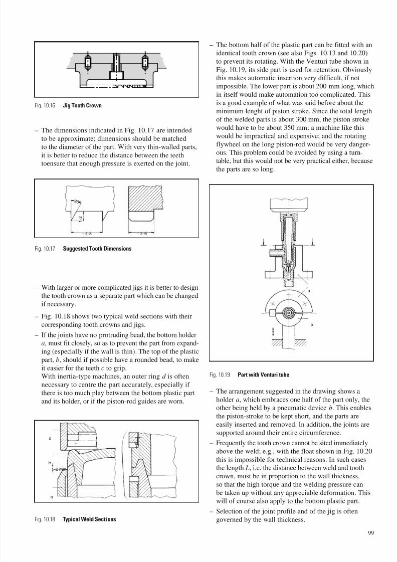
7/23/2019 f1236720 DuPont Engineering Polymers General Design Principles Module I
http://slidepdf.com/reader/full/f1236720-dupont-engineering-polymers-general-design-principles-module-i 101/155
– The dimensions indicated in Fig. 10.17 are intended
to be approximate; dimensions should be matched
to the diameter of the part. With very thin-walled parts,
it is better to reduce the distance between the teethtoensure that enough pressure is exerted on the joint.
– With larger or more complicated jigs it is better to design
the tooth crown as a separate part which can be changedif necessary.
– Fig. 10.18 shows two typical weld sections with their
corresponding tooth crowns and jigs.
– If the joints have no protruding bead, the bottom holdera, must fit closely, so as to prevent the part from expand-
ing (especially if the wall is thin). The top of the plastic
part, b, should if possible have a rounded bead, to make
it easier for the teeth c to grip.With inertia-type machines, an outer ring d is often
necessary to centre the part accurately, especially if
there is too much play between the bottom plastic partand its holder, or if the piston-rod guides are worn.
– The bottom half of the plastic part can be fitted with anidentical tooth crown (see also Figs. 10.13 and 10.20)
to prevent its rotating. With the Venturi tube shown in
Fig. 10.19, its side part is used for retention. Obviously
this makes automatic insertion very difficult, if notimpossible. The lower part is about 200 mm long, which
in itself would make automation too complicated. This
is a good example of what was said before about the
minimum lenght of piston stroke. Since the total lengthof the welded parts is about 300 mm, the piston stroke
would have to be about 350 mm; a machine like this
would be impractical and expensive; and the rotating
flywheel on the long piston-rod would be very danger-ous. This problem could be avoided by using a turn-
table, but this would not be very practical either, because
the parts are so long.
– The arrangement suggested in the drawing shows aholder a, which embraces one half of the part only, theother being held by a pneumatic device b. This enables
the piston-stroke to be kept short, and the parts are
easily inserted and removed. In addition, the joints are
supported around their entire circumference.
– Frequently the tooth crown cannot be sited immediately
above the weld; e.g., with the float shown in Fig. 10.20
this is impossible for technical reasons. In such casesthe length L, i.e. the distance between weld and tooth
crown, must be in proportion to the wall thickness,
so that the high torque and the welding pressure can
be taken up without any appreciable deformation. Thiswill of course also apply to the bottom plastic part.
– Selection of the joint profile and of the jig is often
governed by the wall thickness.
99
3 0 °
1 -
2
~ 4-8 ~ 3-6
b
d
a
c
s
1-2 mm
Fig. 10.16 Jig Tooth Crown
Fig. 10.17 Suggested Tooth Dimensions
Fig. 10.19 Part with Venturi tube
Fig. 10.18 Typical Weld Sections
a
b

7/23/2019 f1236720 DuPont Engineering Polymers General Design Principles Module I
http://slidepdf.com/reader/full/f1236720-dupont-engineering-polymers-general-design-principles-module-i 102/155
Couplings with Interlocking Teeth
Instead of a tooth crown which has to be pressed into the
plastic in order to transmit the torque, toothed couplings
are occasionally used, and matching teeth are moulded
into the plastic part; they may either protrude or be recessed
(as in Fig. 10.21), whichever is more convenient.
The holder a, will have equal and opposing teeth, and
when the plastic part is gripped no damage is caused.Ring faces b inside and outside the coupling will transmit
the welding pressure to the part, so that the teeth, in fact,
transmit only the torque. The number of teeth should be
kept small to reduce the danger of their tips breaking off.
These tips should not be too sharp; the teeth should termi-
nate in a tiny face c 0,3-0,5 mm.
This solution is also suitable for the pivot tools described
before, which do not rotate as fast as inertia machines.
With the high peripheral speed of inertia machines, it is
more difficult to ensure that the teeth engage cleanly.
Cast Resin Couplings
In certain cases it is also possible to drive or grip the parts
by means of elastomer jigs. Synthetic resins are cast directly
into the holding device, the plastic parts forming the other
portion of the mould, so as to get the right-shaped surface.
Since the maximum torque which can be transmitted in
this manner is low, and the permissible pressure per unit
area is low too, this method is only worth considering for
parts having relatively large surfaces.
Conical parts are the most suited to this type of jig (see
Fig. 10.22), because a greater torque can be transmitted
for a given welding pressure.
When this type of jig is used with an inertia machine and
the plastic part has to be accelerated to its welding speed,
there is bound to be a certain amount of slip; this can
cause excessive heating of the surface.
It is therefore extremely important to select a casting resin
of the right hardness; this has to be determined experimen-
tally. Fig. 10.22 shows, in essence, how the cast elastomer
a, also has to be anchored to the metal parts by bolts,
undercuts or slots. The recesses b are machined out after-
wards, because contact here should be avoided.
Making cast resin grips requires a lot of experience and
suitable equipment. The initial costs of this method are
therefore considerable and it has not found many practical
applications.
It may however be economically worth considering formachines with turntables which need several holders.
100
Fig. 10.20 Part with Venturi tube
a
c
-15°
Fig. 10.21 Couplings with interlocking teeth
a
a
b
b
Fig. 10.22 Cast Resin Coupling
L
b
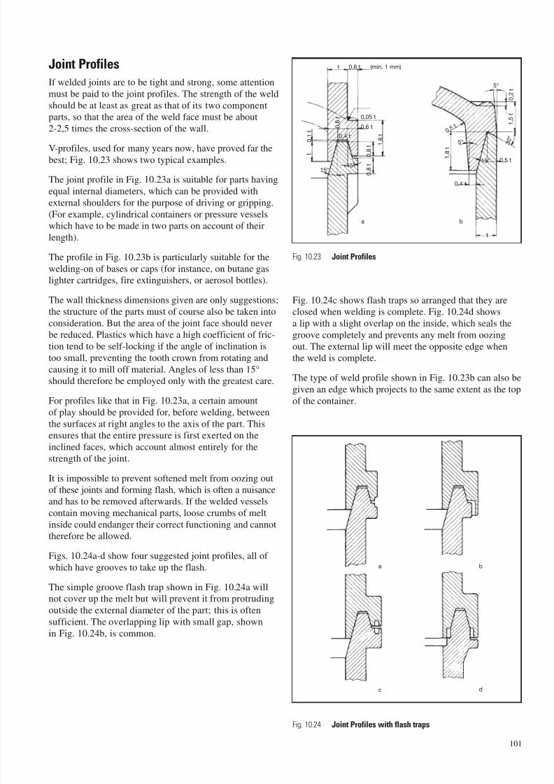
7/23/2019 f1236720 DuPont Engineering Polymers General Design Principles Module I
http://slidepdf.com/reader/full/f1236720-dupont-engineering-polymers-general-design-principles-module-i 103/155
Joint Profiles
If welded joints are to be tight and strong, some attention
must be paid to the joint profiles. The strength of the weld
should be at least as great as that of its two component
parts, so that the area of the weld face must be about
2-2,5 times the cross-section of the wall.
V-profiles, used for many years now, have proved far the
best; Fig. 10.23 shows two typical examples.
The joint profile in Fig. 10.23a is suitable for parts having
equal internal diameters, which can be provided with
external shoulders for the purpose of driving or gripping.
(For example, cylindrical containers or pressure vessels
which have to be made in two parts on account of their
length).
The profile in Fig. 10.23b is particularly suitable for the
welding-on of bases or caps (for instance, on butane gas
lighter cartridges, fire extinguishers, or aerosol bottles).
The wall thickness dimensions given are only suggestions;
the structure of the parts must of course also be taken into
consideration. But the area of the joint face should never
be reduced. Plastics which have a high coefficient of fric-
tion tend to be self-locking if the angle of inclination is
too small, preventing the tooth crown from rotating and
causing it to mill off material. Angles of less than 15°
should therefore be employed only with the greatest care.
For profiles like that in Fig. 10.23a, a certain amount
of play should be provided for, before welding, betweenthe surfaces at right angles to the axis of the part. This
ensures that the entire pressure is first exerted on the
inclined faces, which account almost entirely for the
strength of the joint.
It is impossible to prevent softened melt from oozing out
of these joints and forming flash, which is often a nuisance
and has to be removed afterwards. If the welded vessels
contain moving mechanical parts, loose crumbs of melt
inside could endanger their correct functioning and cannot
therefore be allowed.
Figs. 10.24a-d show four suggested joint profiles, all of
which have grooves to take up the flash.
The simple groove flash trap shown in Fig. 10.24a will
not cover up the melt but will prevent it from protruding
outside the external diameter of the part; this is often
sufficient. The overlapping lip with small gap, shown
in Fig. 10.24b, is common.
Fig. 10.24c shows flash traps so arranged that they are
closed when welding is complete. Fig. 10.24d shows
a lip with a slight overlap on the inside, which seals the
groove completely and prevents any melt from oozing
out. The external lip will meet the opposite edge when
the weld is complete.
The type of weld profile shown in Fig. 10.23b can also be
given an edge which projects to the same extent as the top
of the container.
101
a b
c d
a b
t
0,4 t
15° 0,5 t
5°
1 ,
8
t
3 0 °
1 ,
5
t
0 ,
2
t5°
0, 5 t
15°15°
0 ,
6
t
0,4 t
0,6 t
0,05 t
t 0,6 t (min. 1 mm)
t
0 ,
1
t
0 ,
8
t
0 ,
8
t 1 ,
8
t
Fig. 10.23 Joint Profiles
Fig. 10.24 Joint Profiles with flash traps
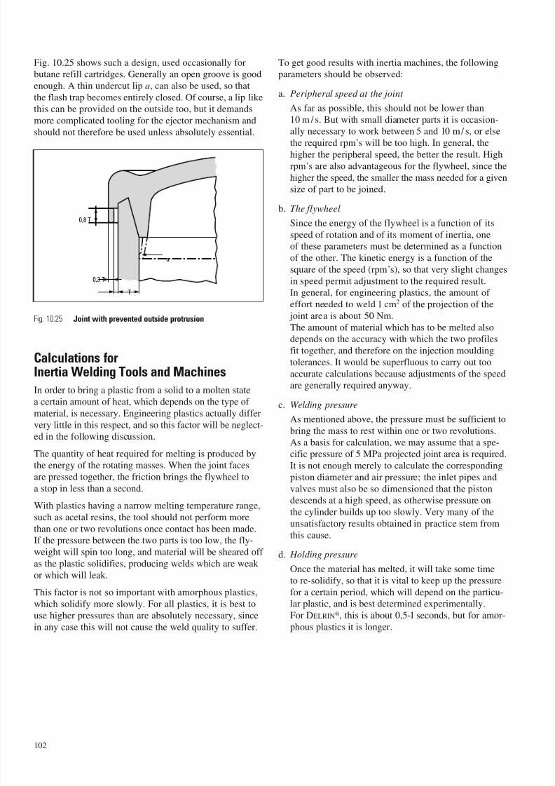
7/23/2019 f1236720 DuPont Engineering Polymers General Design Principles Module I
http://slidepdf.com/reader/full/f1236720-dupont-engineering-polymers-general-design-principles-module-i 104/155
Fig. 10.25 shows such a design, used occasionally forbutane refill cartridges. Generally an open groove is good
enough. A thin undercut lip a, can also be used, so that
the flash trap becomes entirely closed. Of course, a lip likethis can be provided on the outside too, but it demands
more complicated tooling for the ejector mechanism and
should not therefore be used unless absolutely essential.
Calculations forInertia Welding Tools and Machines
In order to bring a plastic from a solid to a molten state
a certain amount of heat, which depends on the type of
material, is necessary. Engineering plastics actually differvery little in this respect, and so this factor will be neglect-ed in the following discussion.
The quantity of heat required for melting is produced bythe energy of the rotating masses. When the joint faces
are pressed together, the friction brings the flywheel to
a stop in less than a second.
With plastics having a narrow melting temperature range,
such as acetal resins, the tool should not perform more
than one or two revolutions once contact has been made.If the pressure between the two parts is too low, the fly-
weight will spin too long, and material will be sheared off as the plastic solidifies, producing welds which are weak
or which will leak.
This factor is not so important with amorphous plastics,
which solidify more slowly. For all plastics, it is best touse higher pressures than are absolutely necessary, since
in any case this will not cause the weld quality to suffer.
To get good results with inertia machines, the followingparameters should be observed:
a. Peripheral speed at the joint
As far as possible, this should not be lower than
10 m / s. But with small diameter parts it is occasion-ally necessary to work between 5 and 10 m/ s, or else
the required rpm’s will be too high. In general, the
higher the peripheral speed, the better the result. High
rpm’s are also advantageous for the flywheel, since the
higher the speed, the smaller the mass needed for a given
size of part to be joined.
b. The flywheel
Since the energy of the flywheel is a function of its
speed of rotation and of its moment of inertia, oneof these parameters must be determined as a function
of the other. The kinetic energy is a function of the
square of the speed (rpm’s), so that very slight changes
in speed permit adjustment to the required result.In general, for engineering plastics, the amount of
effort needed to weld 1 cm2 of the projection of the
joint area is about 50 Nm.
The amount of material which has to be melted alsodepends on the accuracy with which the two profiles
fit together, and therefore on the injection moulding
tolerances. It would be superfluous to carry out too
accurate calculations because adjustments of the speedare generally required anyway.
c. Welding pressure
As mentioned above, the pressure must be sufficient to
bring the mass to rest within one or two revolutions.
As a basis for calculation, we may assume that a spe-cific pressure of 5 MPa projected joint area is required.
It is not enough merely to calculate the corresponding
piston diameter and air pressure; the inlet pipes and
valves must also be so dimensioned that the pistondescends at a high speed, as otherwise pressure on
the cylinder builds up too slowly. Very many of the
unsatisfactory results obtained in practice stem from
this cause.
d. Holding pressure
Once the material has melted, it will take some time
to re-solidify, so that it is vital to keep up the pressure
for a certain period, which will depend on the particu-lar plastic, and is best determined experimentally.
For DELRIN®, this is about 0,5-1 seconds, but for amor-
phous plastics it is longer.
102
0,8 T
0,3 T
a
T
Fig. 10.25 Joint with prevented outside protrusion

7/23/2019 f1236720 DuPont Engineering Polymers General Design Principles Module I
http://slidepdf.com/reader/full/f1236720-dupont-engineering-polymers-general-design-principles-module-i 105/155
Graphical Determinationof Welding Parameters
The most important data can be determined quickly and
easily from the nomogram (Fig. 10.26) which is suitable
for all DuPont engineering plastics.
Example: First determine the mean weld diameter d (Fig. 10.27) and the area of the projection of the joint
surface F .
For the example illustrated, F is about 3 cm2 and the mean
weld diameter d = 60 mm. Starting at 3 cm
2
on the left-hand scale, therefore we proceed towards the right to meetthe line which corresponds to a diameter of 60 (Point 1),
and then proceed vertically upwards. A convenient diam-
eter and associated length of flywheel (see Fig. 10.28) are
chosen. But the diameter should always be greater thanthe length, so as to keep the total length of the rotating
flywheel as small as possible. In the example illustrated,
a diameter of approximately 84 mm has been chosen,
giving a length of 80 mm (Point 2).
The nomogram is based on a peripheral speed of 10 m/s,
which gives about 3200 rpm in this example (60 mm
diameter). A higher speed can be chosen, say 4000 rpm,which corresponds to Point 3. The tool dimensions obtained
by moving upwards from this point will of course be
smaller than before.
In this example we have Point 4, which corresponds toa diameter of 78 mm and a length of 70 mm.
Moving towards the right from the point corresponding
to 3 cm2, the corresponding welding force required is read
off from the right-hand scale; in this case, about 1500 N.
This nomogram considers only the external dimensions of
the tools, and ignores the fact that they are not solid; but
the jig to some extent compensates for this, and the valuesgiven by the nomogram are accurate enough.
103
120
110
100959085
80
75
70
65
60
55
50
20
108654
3
21,5
1
0,80,6
0,40,3
0,2
ø D (mm)
L (mm)
F (cm2 )
10000
5000
3000
2000
P (N)
1000
500
400300
200
100
3 0 4 0 5 0 6 0 7 0 8 0 1 0
0
9 0 1 2 0
8 0 0 0
t / m i
n ø d
2 5 m m
7 0 0 0
2 8
6 0 0 0
3 3
5 0 0 0
4 0
4 0 0 0
5 0
3 5 0 0
5 7
3 0 0 0
6 5
2 5 0 0
8 0
2 0 0 0
1 0 0
1 8 0 0
1 1 0
1 6 0 0
1 2 5
1 4 0 0
1 4 0
1 2 0 0
1 6 5
1 0 0 0
2 0 0
4
2
3 1
Fig. 10.26 Determination of Welding Parameters
Fig. 10.27 Welding Parameters Example
Fig. 10.28 Flywheel Size Example
Ø dØ d
F F
Ø D
P
L
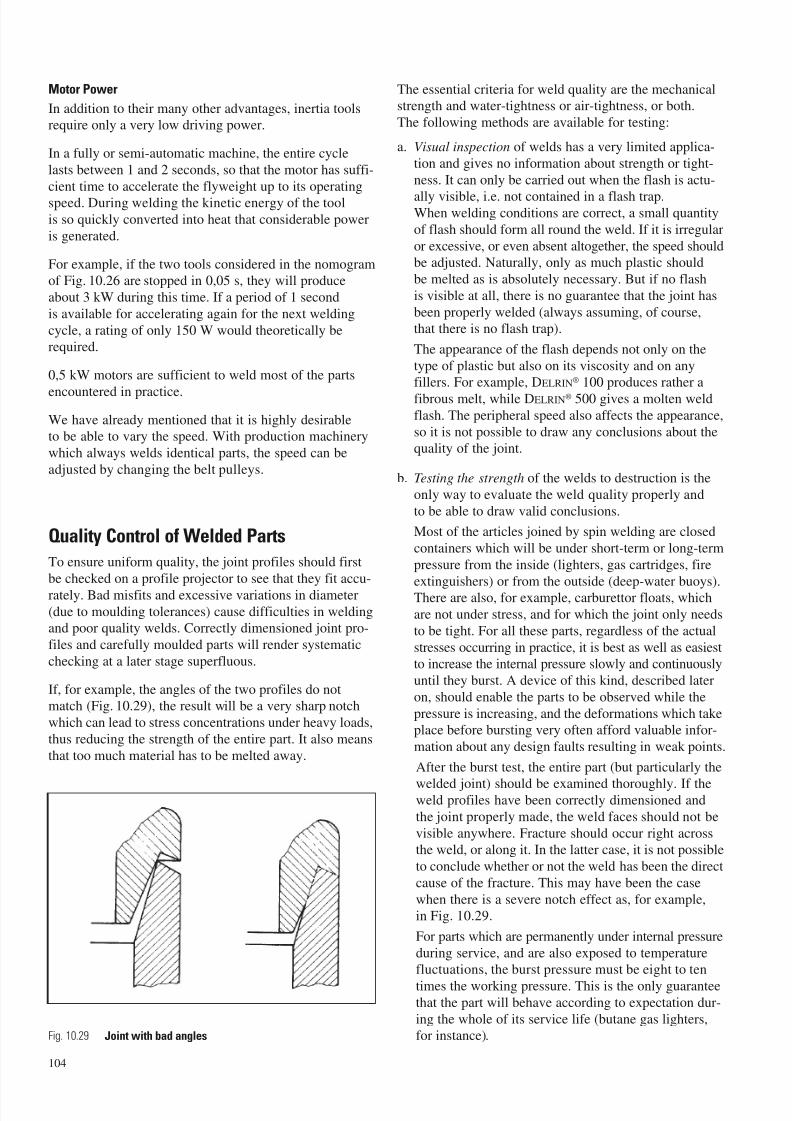
7/23/2019 f1236720 DuPont Engineering Polymers General Design Principles Module I
http://slidepdf.com/reader/full/f1236720-dupont-engineering-polymers-general-design-principles-module-i 106/155
Motor Power
In addition to their many other advantages, inertia toolsrequire only a very low driving power.
In a fully or semi-automatic machine, the entire cycle
lasts between 1 and 2 seconds, so that the motor has suffi-
cient time to accelerate the flyweight up to its operatingspeed. During welding the kinetic energy of the tool
is so quickly converted into heat that considerable power
is generated.
For example, if the two tools considered in the nomogramof Fig. 10.26 are stopped in 0,05 s, they will produce
about 3 kW during this time. If a period of 1 second
is available for accelerating again for the next welding
cycle, a rating of only 150 W would theoretically berequired.
0,5 kW motors are sufficient to weld most of the parts
encountered in practice.
We have already mentioned that it is highly desirableto be able to vary the speed. With production machinery
which always welds identical parts, the speed can be
adjusted by changing the belt pulleys.
Quality Control of Welded Parts
To ensure uniform quality, the joint profiles should first
be checked on a profile projector to see that they fit accu-
rately. Bad misfits and excessive variations in diameter
(due to moulding tolerances) cause difficulties in weldingand poor quality welds. Correctly dimensioned joint pro-
files and carefully moulded parts will render systematic
checking at a later stage superfluous.
If, for example, the angles of the two profiles do notmatch (Fig. 10.29), the result will be a very sharp notch
which can lead to stress concentrations under heavy loads,
thus reducing the strength of the entire part. It also means
that too much material has to be melted away.
The essential criteria for weld quality are the mechanicalstrength and water-tightness or air-tightness, or both.
The following methods are available for testing:
a. Visual inspection of welds has a very limited applica-
tion and gives no information about strength or tight-
ness. It can only be carried out when the flash is actu-
ally visible, i.e. not contained in a flash trap.When welding conditions are correct, a small quantity
of flash should form all round the weld. If it is irregular
or excessive, or even absent altogether, the speed shouldbe adjusted. Naturally, only as much plastic should
be melted as is absolutely necessary. But if no flash
is visible at all, there is no guarantee that the joint has
been properly welded (always assuming, of course,that there is no flash trap).
The appearance of the flash depends not only on the
type of plastic but also on its viscosity and on anyfillers. For example, DELRIN® 100 produces rather a
fibrous melt, while DELRIN® 500 gives a molten weld
flash. The peripheral speed also affects the appearance,
so it is not possible to draw any conclusions about thequality of the joint.
b. Testing the strength of the welds to destruction is the
only way to evaluate the weld quality properly and
to be able to draw valid conclusions.
Most of the articles joined by spin welding are closed
containers which will be under short-term or long-term
pressure from the inside (lighters, gas cartridges, fire
extinguishers) or from the outside (deep-water buoys).There are also, for example, carburettor floats, which
are not under stress, and for which the joint only needs
to be tight. For all these parts, regardless of the actual
stresses occurring in practice, it is best as well as easiestto increase the internal pressure slowly and continuously
until they burst. A device of this kind, described later
on, should enable the parts to be observed while the
pressure is increasing, and the deformations which takeplace before bursting very often afford valuable infor-
mation about any design faults resulting in weak points.
After the burst test, the entire part (but particularly the
welded joint) should be examined thoroughly. If theweld profiles have been correctly dimensioned and
the joint properly made, the weld faces should not be
visible anywhere. Fracture should occur right acrossthe weld, or along it. In the latter case, it is not possible
to conclude whether or not the weld has been the direct
cause of the fracture. This may have been the case
when there is a severe notch effect as, for example,in Fig. 10.29.
For parts which are permanently under internal pressure
during service, and are also exposed to temperaturefluctuations, the burst pressure must be eight to ten
times the working pressure. This is the only guaranteethat the part will behave according to expectation dur-
ing the whole of its service life (butane gas lighters,for instance).
104
Fig. 10.29 Joint with bad angles
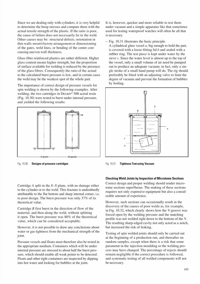
7/23/2019 f1236720 DuPont Engineering Polymers General Design Principles Module I
http://slidepdf.com/reader/full/f1236720-dupont-engineering-polymers-general-design-principles-module-i 107/155
Since we are dealing only with cylinders, it is very helpfulto determine the hoop stresses and compare them with the
actual tensile strength of the plastic. If the ratio is poor,
the cause of failure does not necessarily lie in the weld.
Other causes may be: structural defects, orientation inthin walls unsatisfactory arrangement or dimensioning
of the gates, weld lines, or bending of the centre core
causing uneven wall thickness.
Glass fibre reinforced plastics are rather different. Higher
glass content means higher strength, but the proportionof surface available for welding is reduced by the presence
of the glass fibres. Consequently the ratio of the actual
to the calculated burst pressure is low, and in certain cases
the weld may be the weakest spot of the whole part.
The importance of correct design of pressure vessels for
spin welding is shown by the following examples. Afterwelding, the two cartridges in DELRIN® 500 acetal resin
(Fig. 10.30) were tested to burst under internal pressure,and yielded the following results:
Cartridge A split in the X – X plane, with no damage eitherto the cylinder or to the weld. This fracture is undoubtedly
attributable to the flat bottom and sharp internal corner, i.e.
to poor design. The burst pressure was only 37% of itstheoretical value.
Cartridge B first burst in the direction of flow of the
material, and then along the weld, without splittingit open. The burst pressure was 80% of the theoretical
value, which can be considered acceptable.
However, it is not possible to draw any conclusions about
water or gas tightness from the mechanical strength of the
joint.
Pressure vessels and floats must therefore also be tested in
the appropriate medium. Containers which will be under
internal pressure are stressed to about half the burst pres-sure, which should enable all weak points to be detected.
Floats and other tight containers are inspected by dipping
into hot water and looking for bubbles at the joint.
It is, however, quicker and more reliable to test themunder vacuum and a simple apparatus like that sometimes
used for testing waterproof watches will often be all that
is necessary.
– Fig. 10.31 illustrates the basic principle.
A cylindrical glass vessel a, big enough to hold the part,
is covered with a loose-fitting lid b and sealed with arubber ring. The test piece is kept under water by the
sieve c. Since the water level is almost up to the top of
the vessel, only a small volume of air need be pumpedout to produce an adequate vacuum; in fact, only a sin-
gle stroke of a small hand pump will do. The rig should
preferably be fitted with an adjusting valve to limit the
degree of vacuum and prevent the formation of bubblesby boiling.
Checking Weld Joints by Inspection of Microtome Sections
Correct design and proper welding should render micro-
tome sections superfluous. The making of these sectionsrequires not only expensive equipment but also a consid-
erable amount of experience.
However, such sections can occasionally result in the
discovery of the causes of poor welds as, for example,
in Fig. 10.32, which clearly shows how the V-groove was
forced open by the welding pressure and the matchingprofile was not welded right down to the bottom of the V.
The resulting sharp-edged cavity not only acted as a notch,
but increased the risk of leaking.
Testing of spin welded joints should only be carried out
at the beginning of a production run, and thereafter onrandom samples, except when there is a risk that some
parameter in the injection moulding or the welding pro-
cess may have changed. The percentage of rejects shouldremain negligible if the correct procedure is followed,and systematic testing of all welded components will not
be necessary.
105
A (poor) B (good)
X X
X
a
b
c
d
Fig. 10.30 Designs of pressure cartridges Fig. 10.31 Tightness Test using Vacuum
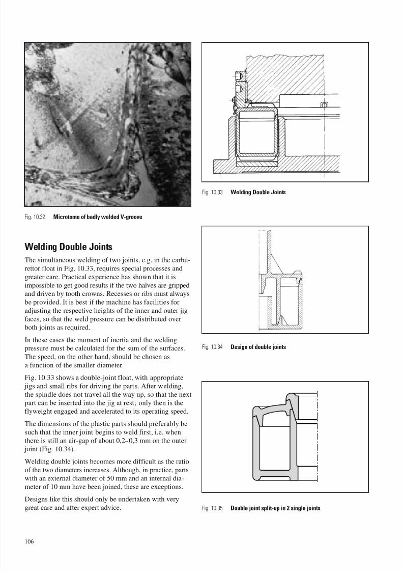
7/23/2019 f1236720 DuPont Engineering Polymers General Design Principles Module I
http://slidepdf.com/reader/full/f1236720-dupont-engineering-polymers-general-design-principles-module-i 108/155
Welding Double Joints
The simultaneous welding of two joints, e.g. in the carbu-
rettor float in Fig. 10.33, requires special processes and
greater care. Practical experience has shown that it is
impossible to get good results if the two halves are grippedand driven by tooth crowns. Recesses or ribs must always
be provided. It is best if the machine has facilities foradjusting the respective heights of the inner and outer jig
faces, so that the weld pressure can be distributed overboth joints as required.
In these cases the moment of inertia and the weldingpressure must be calculated for the sum of the surfaces.
The speed, on the other hand, should be chosen as
a function of the smaller diameter.
Fig. 10.33 shows a double-joint float, with appropriate
jigs and small ribs for driving the parts. After welding,
the spindle does not travel all the way up, so that the next
part can be inserted into the jig at rest; only then is theflyweight engaged and accelerated to its operating speed.
The dimensions of the plastic parts should preferably be
such that the inner joint begins to weld first, i.e. when
there is still an air-gap of about 0,2–0,3 mm on the outer
joint (Fig. 10.34).
Welding double joints becomes more difficult as the ratio
of the two diameters increases. Although, in practice, partswith an external diameter of 50 mm and an internal dia-
meter of 10 mm have been joined, these are exceptions.
Designs like this should only be undertaken with verygreat care and after expert advice.
106
Fig. 10.32 Microtome of badly welded V-groove
Fig. 10.35 Double joint split-up in 2 single joints
Fig. 10.34 Design of double joints
Fig. 10.33 Welding Double Joints
7/23/2019 f1236720 DuPont Engineering Polymers General Design Principles Module I
http://slidepdf.com/reader/full/f1236720-dupont-engineering-polymers-general-design-principles-module-i 109/155
107
In order to avoid all risks, it is better to follow the proce-dure shown in Fig. 10.35. Here the double joint has been
divided into two single ones, which can be welded one
after the other and which pose no problem. This solution
enables the parts to be gripped with tooth crowns in thenormal way, automation is easier, and the total cost is
very little more than for one double joint, while avoiding
long-winded and expensive preliminary testing.
Welding Reinforcedand Dissimilar Plastics
Reinforced plastics can generally be welded just as easily
as unreinforced ones. If the filler reduces the coefficient
of friction, the weld pressure may sometimes have to be
increased so as to reduce the effective weld time.
The weld strength of reinforced plastics is generally lower
because the fibres on the surface do not weld together. Thisis not usually evident in practice, because the joint is not
usually the weakest part. If necessary, the weld profile
can be enlarged somewhat. In all plastics, glass fibres
or fillers reduce tensile elongation, so that stress concen-trations are very harmful. Designers pay far too little
attention to this fact.
Occasionally one is also faced with the problem of joining
plastics of different types, with different melting points.
The greater the difference between the melting points, the
more difficult welding will be, and one cannot call sucha joint a true weld, as it is merely a mechanical adhesion
of the surfaces. The strength of the joint will be low. It mayeven be necessary to have special joint profiles and work
with very high weld pressures.
In practice there are very few such applications, and in all
these cases the parts are not subjected to stresses. Typicalapplications are oil-level gauges and transparent polycar-
bonate spy-holes welded into holders of DELRIN®.
The following test results should give some idea of the
possibilities of joining DELRIN® to other plastics.
The float of DELRIN® shown in Fig. 10.13 has a burst
pressure of about 4 MPa. If a cap of some other materialis welded onto a body of DELRIN®, the burst pressures are
as follows:
ZYTEL® 101 (nylon resin) 0,15–0,7 MPa
Polycarbonate 1,2 –1,9 MPa
Acrylic resin 2,2 –2,4 MPa
ABS 1,2 –1,6 MPa
It must be remembered that, in all these cases, the weld
forms the weakest point.
Spin Welding Soft Plastics and Elastomers
The softer the plastic, with a few exceptions (e.g. fluoro-
polymers), the higher the coefficient of friction. Spin
welding therefore becomes increasingly difficult withsoft plastics, for the following three reasons:
a. The deceleration produced by a high coefficient of
friction is so great that the flyweight is unable to pro-duce heat by friction. Much of the energy is absorbed
in the deformation of the component, without any
relative motion occurring between the joint faces. If
the amount of kinetic energy is increased, one is morelikely to damage the parts than to improve welding
conditions.
It is sometimes possible to solve this problem by spray-ing a lubricant onto the joint faces (e.g. a silicone mould
release). This reduces the coefficient of friction very
considerably at first, so that the usual rotation takes
place. The specific pressure is, however, so high thatthe lubricant is rapidly squeezed out, the friction
increases, and the material melts.
b. For soft plastics having a very low coefficient of fric-
tion a very much higher specific pressure is needed
to produce sufficient heat by friction in a short time.
Most components cannot stand such a high axial pres-sure without being permanently deformed, and there
is to date no reliable way of making satisfactory joints
between these materials by spin welding.
c. Soft plastic parts are difficult to retain and cannot
easily be driven. Transmission of the high torquefrequently poses an insoluble problem, particularlysince it is scarcely possible to use tooth crowns.
To sum up, it can be said that marginal cases of this sortshould be approached only with extreme caution, and that
preliminary experimental work is unavoidable.
Figures 10.36–10.38 show only a few selected examples
out of the great number of possibilities in this field.
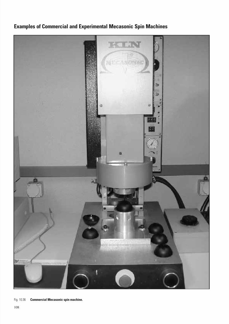
7/23/2019 f1236720 DuPont Engineering Polymers General Design Principles Module I
http://slidepdf.com/reader/full/f1236720-dupont-engineering-polymers-general-design-principles-module-i 110/155
Examples of Commercial and Experimental Mecasonic Spin Machines
108
Fig. 10.36 Commercial Mecasonic spin machine.
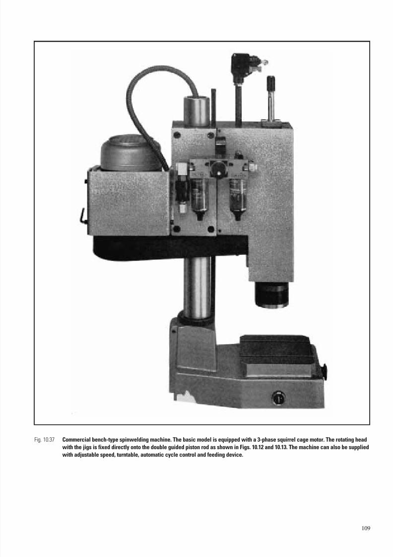
7/23/2019 f1236720 DuPont Engineering Polymers General Design Principles Module I
http://slidepdf.com/reader/full/f1236720-dupont-engineering-polymers-general-design-principles-module-i 111/155
109
Fig. 10.37 Commercial bench-type spinwelding machine. The basic model is equipped with a 3-phase squirrel cage motor. The rotating head
with the jigs is fixed directly onto the double guided piston rod as shown in Figs. 10.12 and 10.13. The machine can also be supplied
with adjustable speed, turntable, automatic cycle control and feeding device.

7/23/2019 f1236720 DuPont Engineering Polymers General Design Principles Module I
http://slidepdf.com/reader/full/f1236720-dupont-engineering-polymers-general-design-principles-module-i 112/155
110
Fig. 10.38 Spinwelding machine.
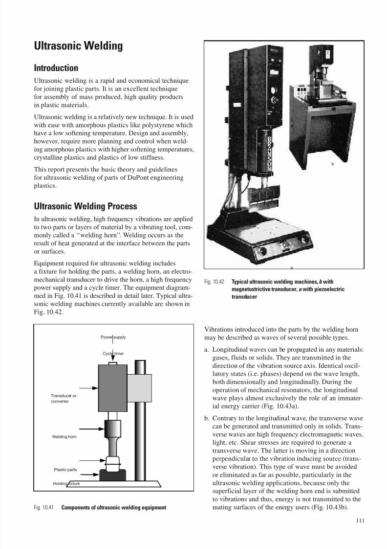
7/23/2019 f1236720 DuPont Engineering Polymers General Design Principles Module I
http://slidepdf.com/reader/full/f1236720-dupont-engineering-polymers-general-design-principles-module-i 113/155
Ultrasonic Welding
Introduction
Ultrasonic welding is a rapid and economical technique
for joining plastic parts. It is an excellent technique
for assembly of mass produced, high quality productsin plastic materials.
Ultrasonic welding is a relatively new technique. It is used
with ease with amorphous plastics like polystyrene whichhave a low softening temperature. Design and assembly,
however, require more planning and control when weld-
ing amorphous plastics with higher softening temperatures,
crystalline plastics and plastics of low stiffness.
This report presents the basic theory and guidelines
for ultrasonic welding of parts of DuPont engineeringplastics.
Ultrasonic Welding Process
In ultrasonic welding, high frequency vibrations are applied
to two parts or layers of material by a vibrating tool, com-monly called a ‘‘welding horn’’. Welding occurs as the
result of heat generated at the interface between the parts
or surfaces.
Equipment required for ultrasonic welding includes
a fixture for holding the parts, a welding horn, an electro-
mechanical transducer to drive the horn, a high frequency
power supply and a cycle timer. The equipment diagram-med in Fig. 10.41 is described in detail later. Typical ultra-
sonic welding machines currently available are shown in
Fig. 10.42.
Vibrations introduced into the parts by the welding horn
may be described as waves of several possible types.
a. Longitudinal waves can be propagated in any materials:
gases, fluids or solids. They are transmitted in the
direction of the vibration source axis. Identical oscil-latory states (i.e. phases) depend on the wave length,
both dimensionally and longitudinally. During theoperation of mechanical resonators, the longitudinal
wave plays almost exclusively the role of an immater-ial energy carrier (Fig. 10.43a).
b. Contrary to the longitudinal wave, the transverse wavecan be generated and transmitted only in solids. Trans-
verse waves are high frequency electromagnetic waves,
light, etc. Shear stresses are required to generate a
transverse wave. The latter is moving in a directionperpendicular to the vibration inducing source (trans-
verse vibration). This type of wave must be avoided
or eliminated as far as possible, particularly in the
ultrasonic welding applications, because only thesuperficial layer of the welding horn end is submitted
to vibrations and thus, energy is not transmitted to the
mating surfaces of the energy users (Fig. 10.43b).
111
Power supply
Cycle timer
Transducer or
converter
Welding horn
Plastic parts
Holding fixture
a
b
Fig. 10.41 Components of ultrasonic welding equipment
Fig. 10.42 Typical ultrasonic welding machines, b with
magnetostrictive transducer, a with piezoelectric transducer
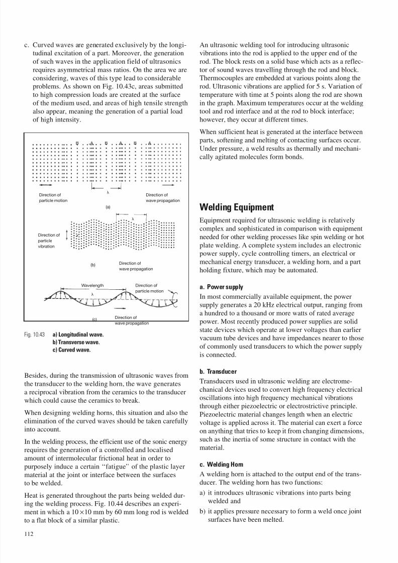
7/23/2019 f1236720 DuPont Engineering Polymers General Design Principles Module I
http://slidepdf.com/reader/full/f1236720-dupont-engineering-polymers-general-design-principles-module-i 114/155
c. Curved waves are generated exclusively by the longi-tudinal excitation of a part. Moreover, the generation
of such waves in the application field of ultrasonics
requires asymmetrical mass ratios. On the area we are
considering, waves of this type lead to considerableproblems. As shown on Fig. 10.43c, areas submitted
to high compression loads are created at the surface
of the medium used, and areas of high tensile strength
also appear, meaning the generation of a partial loadof high intensity.
Besides, during the transmission of ultrasonic waves from
the transducer to the welding horn, the wave generates
a reciprocal vibration from the ceramics to the transducerwhich could cause the ceramics to break.
When designing welding horns, this situation and also the
elimination of the curved waves should be taken carefullyinto account.
In the welding process, the efficient use of the sonic energyrequires the generation of a controlled and localised
amount of intermolecular frictional heat in order to
purposely induce a certain ‘‘fatigue’’ of the plastic layer
material at the joint or interface between the surfacesto be welded.
Heat is generated throughout the parts being welded dur-ing the welding process. Fig. 10.44 describes an experi-
ment in which a 10 ×10 mm by 60 mm long rod is welded
to a flat block of a similar plastic.
An ultrasonic welding tool for introducing ultrasonicvibrations into the rod is applied to the upper end of the
rod. The block rests on a solid base which acts as a reflec-
tor of sound waves travelling through the rod and block.Thermocouples are embedded at various points along the
rod. Ultrasonic vibrations are applied for 5 s. Variation of
temperature with time at 5 points along the rod are shown
in the graph. Maximum temperatures occur at the weldingtool and rod interface and at the rod to block interface;
however, they occur at different times.
When sufficient heat is generated at the interface between
parts, softening and melting of contacting surfaces occur.
Under pressure, a weld results as thermally and mechani-
cally agitated molecules form bonds.
Welding Equipment
Equipment required for ultrasonic welding is relatively
complex and sophisticated in comparison with equipment
needed for other welding processes like spin welding or hot
plate welding. A complete system includes an electronicpower supply, cycle controlling timers, an electrical or
mechanical energy transducer, a welding horn, and a part
holding fixture, which may be automated.
a. Power supply
In most commercially available equipment, the powersupply generates a 20 kHz electrical output, ranging from
a hundred to a thousand or more watts of rated average
power. Most recently produced power supplies are solid
state devices which operate at lower voltages than earliervacuum tube devices and have impedances nearer to those
of commonly used transducers to which the power supply
is connected.
b. Transducer
Transducers used in ultrasonic welding are electrome-
chanical devices used to convert high frequency electricaloscillations into high frequency mechanical vibrations
through either piezoelectric or electrostrictive principle.
Piezoelectric material changes length when an electric
voltage is applied across it. The material can exert a forceon anything that tries to keep it from changing dimensions,
such as the inertia of some structure in contact with the
material.
c. Welding Horn
A welding horn is attached to the output end of the trans-
ducer. The welding horn has two functions:
a) it introduces ultrasonic vibrations into parts beingwelded and
b) it applies pressure necessary to form a weld once joint
surfaces have been melted.
112
B A B A B A
Direction of
particle motion
Direction of
wave propagation
(a)
Direction of
particle
vibration
Direction of
wave propagation
Direction of
wave propagation
(b)
(c)
Wavelength Direction of
particle motion
Fig. 10.43 a) Longitudinal wave.
b) Transverse wave.
c) Curved wave.
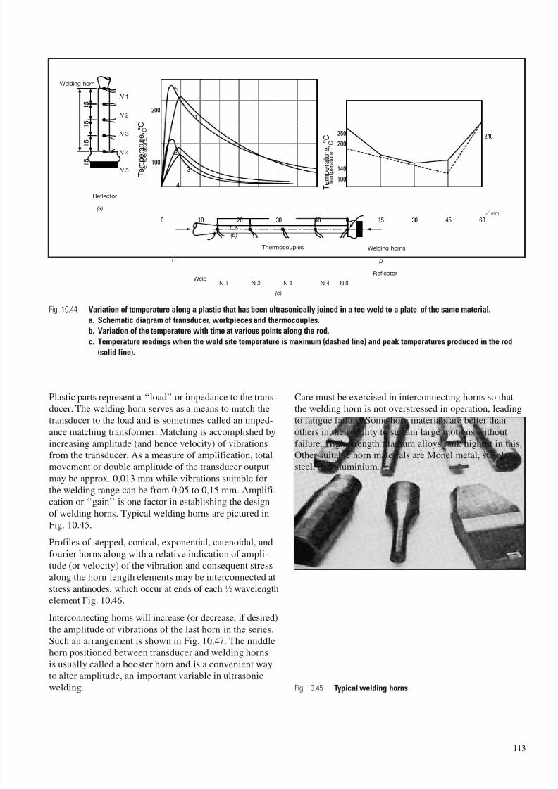
7/23/2019 f1236720 DuPont Engineering Polymers General Design Principles Module I
http://slidepdf.com/reader/full/f1236720-dupont-engineering-polymers-general-design-principles-module-i 115/155
Plastic parts represent a ‘‘load’’ or impedance to the trans-ducer. The welding horn serves as a means to match the
transducer to the load and is sometimes called an imped-
ance matching transformer. Matching is accomplished by
increasing amplitude (and hence velocity) of vibrationsfrom the transducer. As a measure of amplification, total
movement or double amplitude of the transducer output
may be approx. 0,013 mm while vibrations suitable for
the welding range can be from 0,05 to 0,15 mm. Amplifi-cation or ‘‘gain’’ is one factor in establishing the design
of welding horns. Typical welding horns are pictured in
Fig. 10.45.
Profiles of stepped, conical, exponential, catenoidal, and
fourier horns along with a relative indication of ampli-tude (or velocity) of the vibration and consequent stressalong the horn length elements may be interconnected at
stress antinodes, which occur at ends of each 1 ⁄ 2 wavelength
element Fig. 10.46.
Interconnecting horns will increase (or decrease, if desired)
the amplitude of vibrations of the last horn in the series.
Such an arrangement is shown in Fig. 10.47. The middlehorn positioned between transducer and welding horns
is usually called a booster horn and is a convenient way
to alter amplitude, an important variable in ultrasonic
welding.
Care must be exercised in interconnecting horns so thatthe welding horn is not overstressed in operation, leading
to fatigue failure. Some horn materials are better than
others in their ability to sustain large motions without
failure. High strength titanium alloys rank highest in this.Other suitable horn materials are Monel metal, stainless
steel, and aluminium.
113
20100
5
1
2
3
4
1 5
1 5
1 5
1 5
30 40 0 15 30 45 60
100140
100
240200
250
200
T e m p e r a t u r e ,
° C
T e m p e r a t u r e
, ° C
Welding horn
(a)
N 1
N 2
N 3
N 4
N 5
t , s
(b)
Welding horns
Reflector
p
Thermocouples
N 1 N 2 N 3 N 4 N 5
(c)
Weld
p
Fig. 10.44 Variation of temperature along a plastic that has been ultrasonically joined in a tee weld to a plate of the same material.
a. Schematic diagram of transducer, workpieces and thermocouples.
b. Variation of the temperature with time at various points along the rod.
c. Temperature readings when the weld site temperature is maximum (dashed line) and peak temperatures produced in the rod
(solid line).
Fig. 10.45 Typical welding horns
T e m p e r a
t u r e ,
° C
T e m p e r a
t u r e ,
° C
l , mm
Reflector
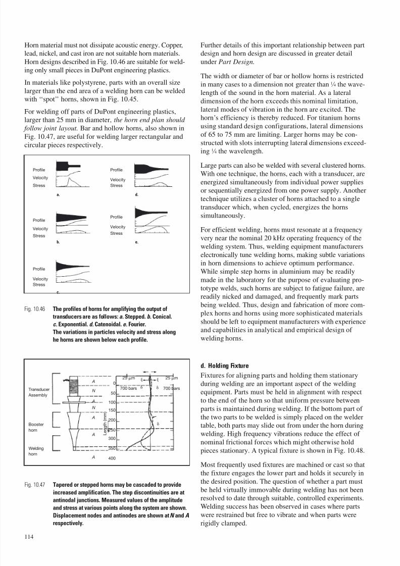
7/23/2019 f1236720 DuPont Engineering Polymers General Design Principles Module I
http://slidepdf.com/reader/full/f1236720-dupont-engineering-polymers-general-design-principles-module-i 116/155
Horn material must not dissipate acoustic energy. Copper,lead, nickel, and cast iron are not suitable horn materials.
Horn designs described in Fig. 10.46 are suitable for weld-
ing only small pieces in DuPont engineering plastics.
In materials like polystyrene, parts with an overall size
larger than the end area of a welding horn can be welded
with ‘‘spot’’ horns, shown in Fig. 10.45.
For welding off parts of DuPont engineering plastics,larger than 25 mm in diameter, the horn end plan should
follow joint layout. Bar and hollow horns, also shown in
Fig. 10.47, are useful for welding larger rectangular and
circular pieces respectively.
Further details of this important relationship between partdesign and horn design are discussed in greater detail
under Part Design.
The width or diameter of bar or hollow horns is restrictedin many cases to a dimension not greater than 1 ⁄ 4 the wave-
length of the sound in the horn material. As a lateral
dimension of the horn exceeds this nominal limitation,lateral modes of vibration in the horn are excited. Thehorn’s efficiency is thereby reduced. For titanium horns
using standard design configurations, lateral dimensions
of 65 to 75 mm are limiting. Larger horns may be con-
structed with slots interrupting lateral dimensions exceed-ing 1 ⁄ 4 the wavelength.
Large parts can also be welded with several clustered horns.
With one technique, the horns, each with a transducer, are
energized simultaneously from individual power suppliesor sequentially energized from one power supply. Another
technique utilizes a cluster of horns attached to a singletransducer which, when cycled, energizes the horns
simultaneously.
For efficient welding, horns must resonate at a frequency
very near the nominal 20 kHz operating frequency of the
welding system. Thus, welding equipment manufacturers
electronically tune welding horns, making subtle variationsin horn dimensions to achieve optimum performance.
While simple step horns in aluminium may be readily
made in the laboratory for the purpose of evaluating pro-
totype welds, such horns are subject to fatigue failure, are
readily nicked and damaged, and frequently mark partsbeing welded. Thus, design and fabrication of more com-
plex horns and horns using more sophisticated materials
should be left to equipment manufacturers with experienceand capabilities in analytical and empirical design of
welding horns.
d. Holding Fixture
Fixtures for aligning parts and holding them stationary
during welding are an important aspect of the weldingequipment. Parts must be held in alignment with respect
to the end of the horn so that uniform pressure between
parts is maintained during welding. If the bottom part of
the two parts to be welded is simply placed on the weldertable, both parts may slide out from under the horn during
welding. High frequency vibrations reduce the effect of
nominal frictional forces which might otherwise hold
pieces stationary. A typical fixture is shown in Fig. 10.48.
Most frequently used fixtures are machined or cast so that
the fixture engages the lower part and holds it securely in
the desired position. The question of whether a part must
be held virtually immovable during welding has not been
resolved to date through suitable, controlled experiments.Welding success has been observed in cases where parts
were restrained but free to vibrate and when parts were
rigidly clamped.
114
Transducer
Assembly
Booster
horn
Welding
horn
A
N
A
N
A
A
A
0
50
100
150
200
250
300
350
400
L e n g
t h ( m m
)
25 m
700 bars
0
25 m
700 bars
Profile
Velocity
Stress
Profile
Velocity
Stress
Profile
Velocity
Stress
Profile
Velocity
Stress
Profile
Velocity
Stress
Fig. 10.46 The profiles of horns for amplifying the output of
transducers are as follows: a. Stepped. b. Conical.
c. Exponential. d. Catenoidal. e. Fourier.
The variations in particles velocity and stress along
he horns are shown below each profile.
Fig. 10.47 Tapered or stepped horns may be cascaded to provide
increased amplification. The step discontinuities are at
antinodal junctions. Measured values of the amplitude
and stress at various points along the system are shown.
Displacement nodes and antinodes are shown at N and A
respectively.
a.
b.
d.
e.
c.
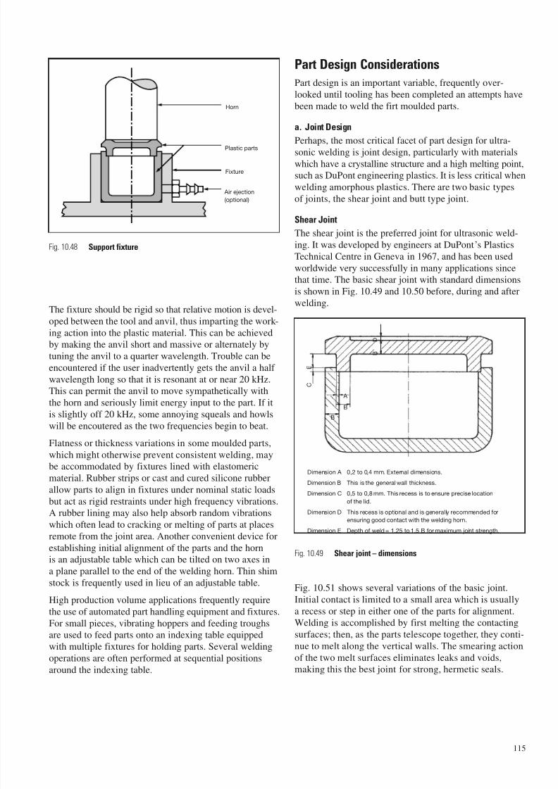
7/23/2019 f1236720 DuPont Engineering Polymers General Design Principles Module I
http://slidepdf.com/reader/full/f1236720-dupont-engineering-polymers-general-design-principles-module-i 117/155
The fixture should be rigid so that relative motion is devel-
oped between the tool and anvil, thus imparting the work-
ing action into the plastic material. This can be achievedby making the anvil short and massive or alternately by
tuning the anvil to a quarter wavelength. Trouble can be
encountered if the user inadvertently gets the anvil a half
wavelength long so that it is resonant at or near 20 kHz.This can permit the anvil to move sympathetically with
the horn and seriously limit energy input to the part. If it
is slightly off 20 kHz, some annoying squeals and howlswill be encoutered as the two frequencies begin to beat.
Flatness or thickness variations in some moulded parts,
which might otherwise prevent consistent welding, maybe accommodated by fixtures lined with elastomeric
material. Rubber strips or cast and cured silicone rubber
allow parts to align in fixtures under nominal static loads
but act as rigid restraints under high frequency vibrations.A rubber lining may also help absorb random vibrations
which often lead to cracking or melting of parts at places
remote from the joint area. Another convenient device for
establishing initial alignment of the parts and the hornis an adjustable table which can be tilted on two axes in
a plane parallel to the end of the welding horn. Thin shim
stock is frequently used in lieu of an adjustable table.
High production volume applications frequently require
the use of automated part handling equipment and fixtures.
For small pieces, vibrating hoppers and feeding troughsare used to feed parts onto an indexing table equipped
with multiple fixtures for holding parts. Several welding
operations are often performed at sequential positions
around the indexing table.
Part Design Considerations
Part design is an important variable, frequently over-
looked until tooling has been completed an attempts have
been made to weld the firt moulded parts.
a. Joint Design
Perhaps, the most critical facet of part design for ultra-sonic welding is joint design, particularly with materials
which have a crystalline structure and a high melting point,such as DuPont engineering plastics. It is less critical when
welding amorphous plastics. There are two basic types
of joints, the shear joint and butt type joint.
Shear Joint
The shear joint is the preferred joint for ultrasonic weld-
ing. It was developed by engineers at DuPont’s Plastics
Technical Centre in Geneva in 1967, and has been used
worldwide very successfully in many applications since
that time. The basic shear joint with standard dimensionsis shown in Fig. 10.49 and 10.50 before, during and after
welding.
Fig. 10.51 shows several variations of the basic joint.
Initial contact is limited to a small area which is usually
a recess or step in either one of the parts for alignment.Welding is accomplished by first melting the contacting
surfaces; then, as the parts telescope together, they conti-
nue to melt along the vertical walls. The smearing action
of the two melt surfaces eliminates leaks and voids,making this the best joint for strong, hermetic seals.
115
Horn
Plastic parts
Fixture
Air ejection
(optional)
Fig. 10.48 Support fixture
A
B
B
C
E
B
D
Dimension A 0,2 to 0,4 mm. External dimensions.
Dimension B This is the general wall thickness.
Dimension C 0,5 to 0,8 mm. This recess is to ensure precise location
of the lid.
Dimension D This recess is optional and is generally recommended for
ensuring good contact with the welding horn.
Dimension E Depth of weld = 1,25 to 1,5 B for maximum joint strength.
Fig. 10.49 Shear joint – dimensions
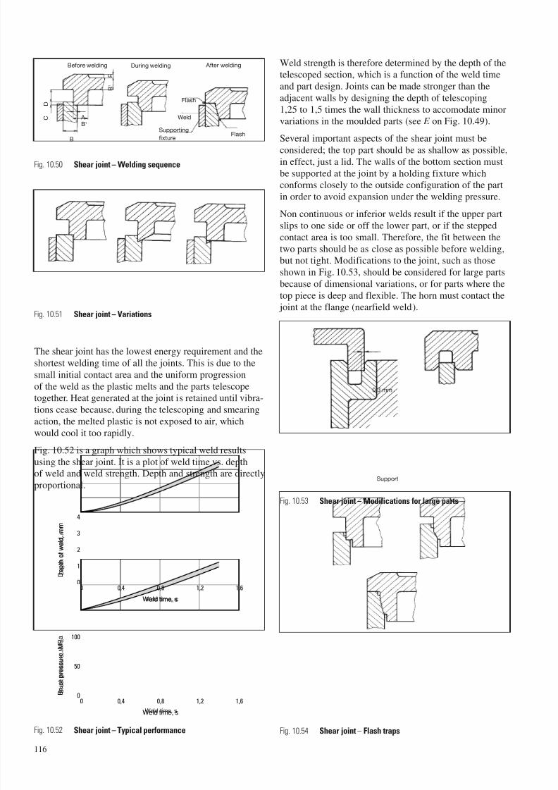
7/23/2019 f1236720 DuPont Engineering Polymers General Design Principles Module I
http://slidepdf.com/reader/full/f1236720-dupont-engineering-polymers-general-design-principles-module-i 118/155
The shear joint has the lowest energy requirement and the
shortest welding time of all the joints. This is due to the
small initial contact area and the uniform progression
of the weld as the plastic melts and the parts telescopetogether. Heat generated at the joint is retained until vibra-
tions cease because, during the telescoping and smearing
action, the melted plastic is not exposed to air, which
would cool it too rapidly.
Fig. 10.52 is a graph which shows typical weld results
using the shear joint. It is a plot of weld time vs. depthof weld and weld strength. Depth and strength are directly
proportional.
Weld strength is therefore determined by the depth of thetelescoped section, which is a function of the weld time
and part design. Joints can be made stronger than the
adjacent walls by designing the depth of telescoping
1,25 to 1,5 times the wall thickness to accomodate minorvariations in the moulded parts (see E on Fig. 10.49).
Several important aspects of the shear joint must beconsidered; the top part should be as shallow as possible,
in effect, just a lid. The walls of the bottom section must
be supported at the joint by a holding fixture whichconforms closely to the outside configuration of the part
in order to avoid expansion under the welding pressure.
Non continuous or inferior welds result if the upper part
slips to one side or off the lower part, or if the stepped
contact area is too small. Therefore, the fit between the
two parts should be as close as possible before welding,but not tight. Modifications to the joint, such as those
shown in Fig. 10.53, should be considered for large partsbecause of dimensional variations, or for parts where the
top piece is deep and flexible. The horn must contact the joint at the flange (nearfield weld).
116
Before welding During welding After welding
Flash
Weld
FlashSupporting
fixture
C
D
A B1
B
B 1
E
Fig. 10.50 Shear joint – Welding sequence
Fig. 10.51 Shear joint – Variations
Fig. 10.53 Shear joint – Modifications for large parts
Fig. 10.54 Shear joint – Flash trapsFig. 10.52 Shear joint – Typical performance
0,80 0,4 1,2 1,6
0,80 0,4 1,2 1,6
1
0
2
3
4
50
100
0
Weld time, s
D e p t h o f
w e l d , m m
Weld time, s
B r u s t p r e s s u r e ,
M P a
0,3 mm
Support
B
r u s
t p r e s s u r e ,
M P a
D e p
t h o f
w e
l d ,
m m
Weld time, s
Weld time, s
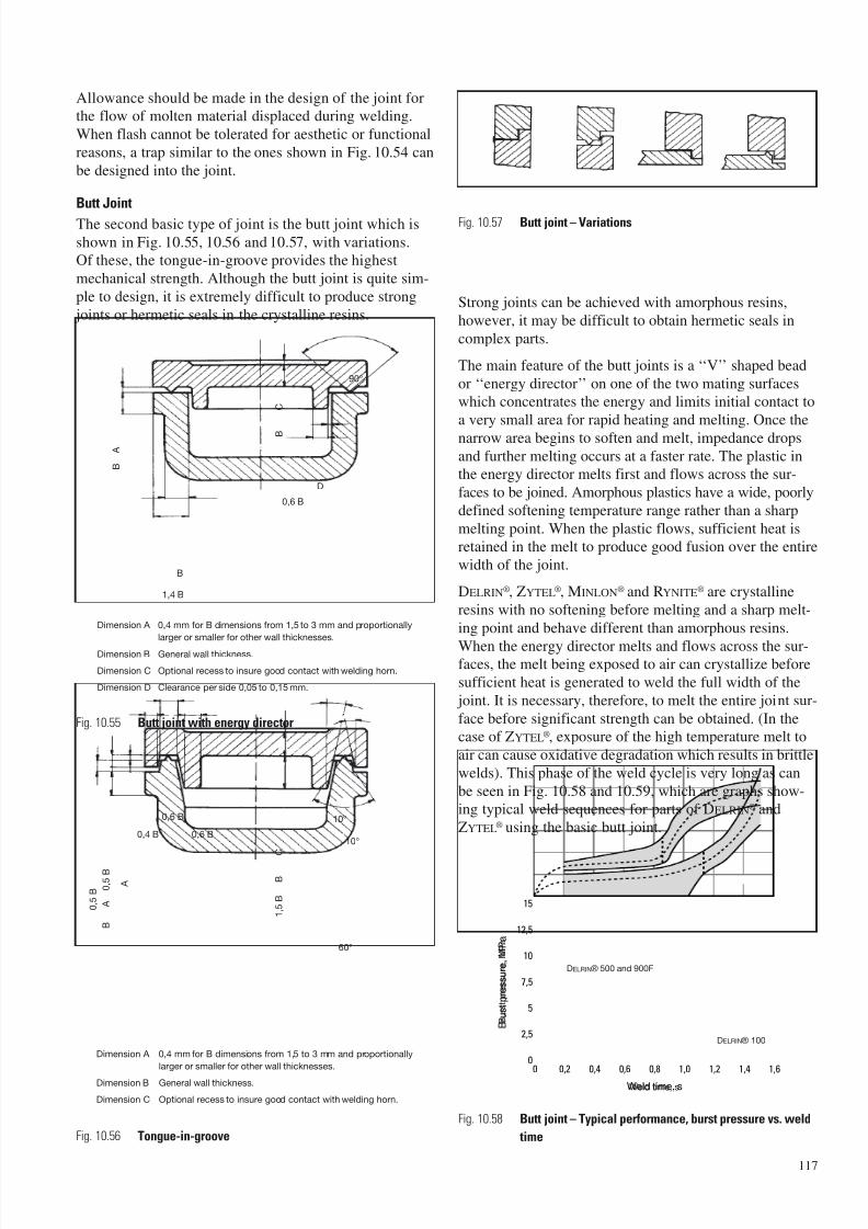
7/23/2019 f1236720 DuPont Engineering Polymers General Design Principles Module I
http://slidepdf.com/reader/full/f1236720-dupont-engineering-polymers-general-design-principles-module-i 119/155
Allowance should be made in the design of the joint forthe flow of molten material displaced during welding.
When flash cannot be tolerated for aesthetic or functional
reasons, a trap similar to the ones shown in Fig. 10.54 can
be designed into the joint.
Butt Joint
The second basic type of joint is the butt joint which is
shown in Fig. 10.55, 10.56 and 10.57, with variations.Of these, the tongue-in-groove provides the highest
mechanical strength. Although the butt joint is quite sim-
ple to design, it is extremely difficult to produce strong
joints or hermetic seals in the crystalline resins.Strong joints can be achieved with amorphous resins,
however, it may be difficult to obtain hermetic seals in
complex parts.
The main feature of the butt joints is a ‘‘V’’ shaped bead
or ‘‘energy director’’ on one of the two mating surfaceswhich concentrates the energy and limits initial contact to
a very small area for rapid heating and melting. Once the
narrow area begins to soften and melt, impedance drops
and further melting occurs at a faster rate. The plastic inthe energy director melts first and flows across the sur-
faces to be joined. Amorphous plastics have a wide, poorly
defined softening temperature range rather than a sharp
melting point. When the plastic flows, sufficient heat isretained in the melt to produce good fusion over the entire
width of the joint.
DELRIN®, ZYTEL®, MINLON® and RYNITE® are crystalline
resins with no softening before melting and a sharp melt-
ing point and behave different than amorphous resins.
When the energy director melts and flows across the sur-faces, the melt being exposed to air can crystallize before
sufficient heat is generated to weld the full width of the
joint. It is necessary, therefore, to melt the entire joint sur-
face before significant strength can be obtained. (In thecase of ZYTEL®, exposure of the high temperature melt to
air can cause oxidative degradation which results in brittle
welds). This phase of the weld cycle is very long as can
be seen in Fig. 10.58 and 10.59, which are graphs show-ing typical weld sequences for parts of DELRIN® and
ZYTEL® using the basic butt joint.
117
Dimension A 0,4 mm for B dimensions from 1,5 to 3 mm and proportionally
larger or smaller for other wall thicknesses.
Dimension B General wall thickness.
Dimension C Optional recess to insure good contact with welding horn.
Dimension D Clearance per side 0,05 to 0,15 mm.
Dimension A 0,4 mm for B dimensions from 1,5 to 3 mm and proportionally
larger or smaller for other wall thicknesses.
Dimension B General wall thickness.
Dimension C Optional recess to insure good contact with welding horn.
60°
10°
10°
0,6 B
0,6 B0,4 B
1 , 5
B
B
C
A
0 , 5
B
B
A
0 , 5
B
90°
D
0,6 B
B
1,4 B
B
A
B
C
Fig. 10.55 Butt joint with energy director
Fig. 10.57 Butt joint – Variations
Fig. 10.58 Butt joint – Typical performance, burst pressure vs. weld
timeFig. 10.56 Tongue-in-groove
0 0,40,2 0,80,6 1,21,0 1,61,4
7,5
10
12,5
15
5
2,5
0
Weld time, s
B r u s t p r e s s u r e ,
M P a
DELRIN® 500 and 900F
DELRIN® 100
Weld time, s
B u r s
t p r e s s u r e ,
M P a
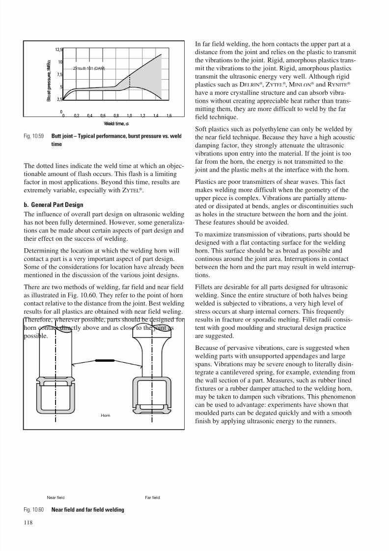
7/23/2019 f1236720 DuPont Engineering Polymers General Design Principles Module I
http://slidepdf.com/reader/full/f1236720-dupont-engineering-polymers-general-design-principles-module-i 120/155
The dotted lines indicate the weld time at which an objec-tionable amount of flash occurs. This flash is a limiting
factor in most applications. Beyond this time, results are
extremely variable, especially with ZYTEL
®
.
b. General Part Design
The influence of overall part design on ultrasonic welding
has not been fully determined. However, some generaliza-
tions can be made about certain aspects of part design and
their effect on the success of welding.
Determining the location at which the welding horn will
contact a part is a very important aspect of part design.Some of the considerations for location have already been
mentioned in the discussion of the various joint designs.
There are two methods of welding, far field and near fieldas illustrated in Fig. 10.60. They refer to the point of horn
contact relative to the distance from the joint. Best welding
results for all plastics are obtained with near field weling.Therefore, wherever possible, parts should be designed for
horn contact directly above and as close to the joint as
possible.
In far field welding, the horn contacts the upper part at adistance from the joint and relies on the plastic to transmit
the vibrations to the joint. Rigid, amorphous plastics trans-
mit the vibrations to the joint. Rigid, amorphous plastics
transmit the ultrasonic energy very well. Although rigidplastics such as DELRIN®, ZYTEL®, MINLON® and RYNITE®
have a more crystalline structure and can absorb vibra-
tions without creating appreciable heat rather than trans-mitting them, they are more difficult to weld by the far
field technique.
Soft plastics such as polyethylene can only be welded by
the near field technique. Because they have a high acoustic
damping factor, they strongly attenuate the ultrasonic
vibrations upon entry into the material. If the joint is toofar from the horn, the energy is not transmitted to the
joint and the plastic melts at the interface with the horn.
Plastics are poor transmitters of shear waves. This fact
makes welding more difficult when the geometry of theupper piece is complex. Vibrations are partially attenu-
ated or dissipated at bends, angles or discontinuities suchas holes in the structure between the horn and the joint.
These features should be avoided.
To maximize transmission of vibrations, parts should be
designed with a flat contacting surface for the welding
horn. This surface should be as broad as possible and
continous around the joint area. Interruptions in contactbetween the horn and the part may result in weld interrup-
tions.
Fillets are desirable for all parts designed for ultrasonicwelding. Since the entire structure of both halves being
welded is subjected to vibrations, a very high level of
stress occurs at sharp internal corners. This frequentlyresults in fracture or sporadic melting. Fillet radii consis-
tent with good moulding and structural design practice
are suggested.
Because of pervasive vibrations, care is suggested when
welding parts with unsupported appendages and large
spans. Vibrations may be severe enough to literally disin-tegrate a cantilevered spring, for example, extending from
the wall section of a part. Measures, such as rubber lined
fixtures or a rubber damper attached to the welding horn,may be taken to dampen such vibrations. This phenomenoncan be used to advantage: experiments have shown that
moulded parts can be degated quickly and with a smooth
finish by applying ultrasonic energy to the runners.
118
Fig. 10.59 Butt joint – Typical performance, burst pressure vs. weld
time
0 0,2 0,4 0,6 0,8 1,0 1,2 1,4 1,6
2,5
0
7,5
5
10
12,5
Weld time, s
B r u
s t p r e s s u r e ,
M P a
ZYTEL® 101 (DAM)
Horn
Near field Far field
Fig. 10.60 Near field and far field welding
Weld time, s
B r u s
t p r e s s u r e ,
M P a
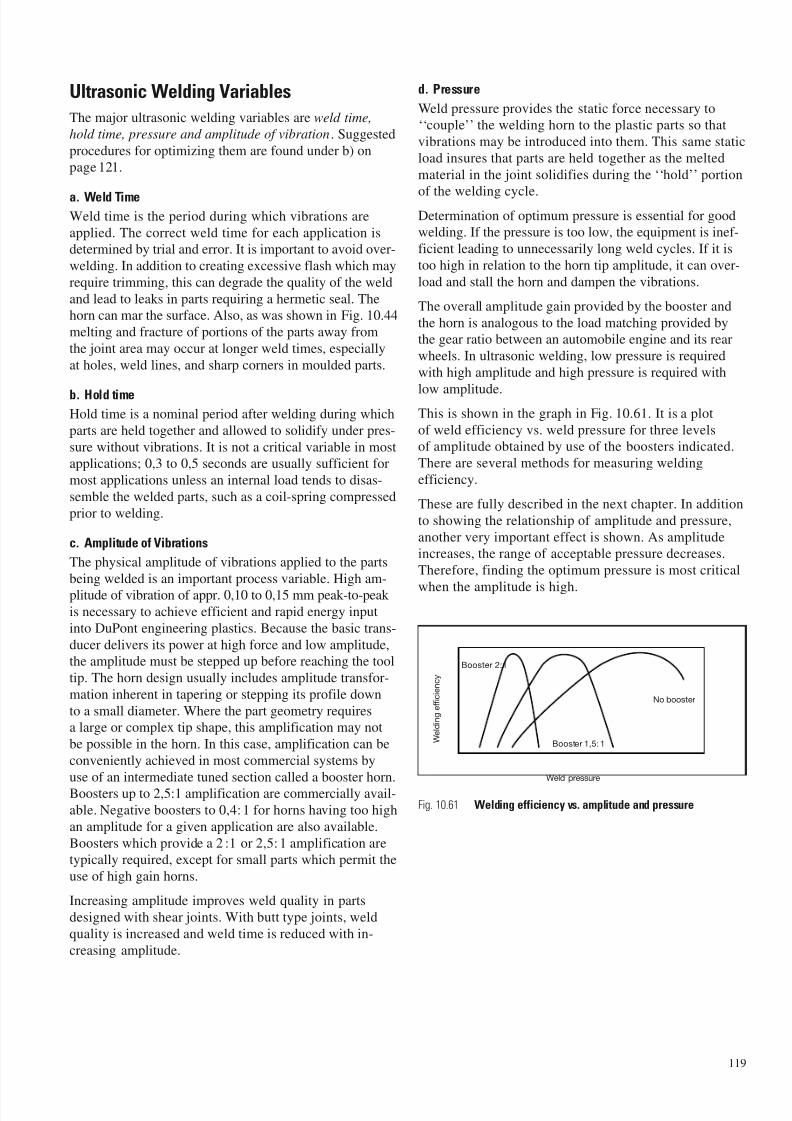
7/23/2019 f1236720 DuPont Engineering Polymers General Design Principles Module I
http://slidepdf.com/reader/full/f1236720-dupont-engineering-polymers-general-design-principles-module-i 121/155
Ultrasonic Welding Variables
The major ultrasonic welding variables are weld time,
hold time, pressure and amplitude of vibration. Suggested
procedures for optimizing them are found under b) onpage 121.
a. Weld TimeWeld time is the period during which vibrations are
applied. The correct weld time for each application isdetermined by trial and error. It is important to avoid over-
welding. In addition to creating excessive flash which may
require trimming, this can degrade the quality of the weld
and lead to leaks in parts requiring a hermetic seal. Thehorn can mar the surface. Also, as was shown in Fig. 10.44
melting and fracture of portions of the parts away from
the joint area may occur at longer weld times, especially
at holes, weld lines, and sharp corners in moulded parts.
b. Hold timeHold time is a nominal period after welding during which
parts are held together and allowed to solidify under pres-
sure without vibrations. It is not a critical variable in mostapplications; 0,3 to 0,5 seconds are usually sufficient for
most applications unless an internal load tends to disas-
semble the welded parts, such as a coil-spring compressed
prior to welding.
c. Amplitude of Vibrations
The physical amplitude of vibrations applied to the parts
being welded is an important process variable. High am-plitude of vibration of appr. 0,10 to 0,15 mm peak-to-peak
is necessary to achieve efficient and rapid energy input
into DuPont engineering plastics. Because the basic trans-
ducer delivers its power at high force and low amplitude,the amplitude must be stepped up before reaching the tool
tip. The horn design usually includes amplitude transfor-
mation inherent in tapering or stepping its profile down
to a small diameter. Where the part geometry requiresa large or complex tip shape, this amplification may not
be possible in the horn. In this case, amplification can be
conveniently achieved in most commercial systems by
use of an intermediate tuned section called a booster horn.Boosters up to 2,5:1 amplification are commercially avail-
able. Negative boosters to 0,4:1 for horns having too high
an amplitude for a given application are also available.
Boosters which provide a 2 :1 or 2,5:1 amplification aretypically required, except for small parts which permit the
use of high gain horns.
Increasing amplitude improves weld quality in parts
designed with shear joints. With butt type joints, weld
quality is increased and weld time is reduced with in-
creasing amplitude.
d. Pressure
Weld pressure provides the static force necessary to
‘‘couple’’ the welding horn to the plastic parts so that
vibrations may be introduced into them. This same static
load insures that parts are held together as the melted
material in the joint solidifies during the ‘‘hold’’ portion
of the welding cycle.Determination of optimum pressure is essential for goodwelding. If the pressure is too low, the equipment is inef-
ficient leading to unnecessarily long weld cycles. If it is
too high in relation to the horn tip amplitude, it can over-
load and stall the horn and dampen the vibrations.
The overall amplitude gain provided by the booster and
the horn is analogous to the load matching provided bythe gear ratio between an automobile engine and its rear
wheels. In ultrasonic welding, low pressure is required
with high amplitude and high pressure is required with
low amplitude.This is shown in the graph in Fig. 10.61. It is a plot
of weld efficiency vs. weld pressure for three levelsof amplitude obtained by use of the boosters indicated.
There are several methods for measuring welding
efficiency.
These are fully described in the next chapter. In addition
to showing the relationship of amplitude and pressure,
another very important effect is shown. As amplitudeincreases, the range of acceptable pressure decreases.
Therefore, finding the optimum pressure is most critical
when the amplitude is high.
119
Fig. 10.61 Welding efficiency vs. amplitude and pressure
Booster 2:1
No booster
Booster 1,5: 1
Weld pressure
W e
l d i n g e
f f i c i e n c y
7/23/2019 f1236720 DuPont Engineering Polymers General Design Principles Module I
http://slidepdf.com/reader/full/f1236720-dupont-engineering-polymers-general-design-principles-module-i 122/155
Guide to Equipment Operation
Proper operation of welding equipment is critical to the
success of ultrasonic welding. The following comments
are suggested as a guide to the use of ultrasonic weldingmachines with parts of DuPont engineering plastics.
a. Initial Equipment Setup
Horn Installation
The transducer, welding horn, and booster horn (if needed)
must be tightly bolted together to insure efficient transmis-sion of vibrations from the transducer to the parts. The end
surfaces of the transducer output and horns are usually
flat to within several microns. However, to insure efficient
coupling heavy silicone grease or a thin brass or copperwasher cur from 0,05 or 0,08 mm shin stock is used
between horns. Long spanner wrenches are used to tighten
horns. Care must be exercised when tightening horns, soas not to turn the transducer output end. Such turning maypull the electrical leads from the transducer.
After installation of the horns, some welders require manual
tuning of the electronic power supply. Small, but important
adjustments to the frequency of power supply are made
to exactly match its frequency to that of the horns. Somewelders accomplish this tuning automatically. The opera-
tions manual for a particular welder will indicate required
tuning procedures, if any. This procedure must be repeated
each time a horn or booster is changed.
If the amplitude of vibration of a horn is not known, itmay be determined quite simply with either a microscopeor a dial indicator. A booster should not be used if only
the amplitude of the welding horn is to be determined.
A 100 × microscope with a calibrated reticule in the eye
piece is suitable for making optical measurements.When magnified, the machined surface of the horn appears
as bright and dark peaks and valleys respectively. When
the horn is vibrating, a peak will blur out into a streak and
the length of the streak is the peak-to-peak amplitude ortotal up and down excursion of the end of the horn.
A machinist’s dial indicator may be used to measure ‘‘am-
plitude’’ or half the total movement of the horn. The dialindicator is positioned with an indicator tip contacting the
bottom surface of the horn and in an attitude such that the
tip moves in a vertical direction. The indicator is set to zerowith the horn stationary. When the horn is vibrating, it will
deflect the indicator tip downward.
Since the indicator cannot respond to the horns rapid
movement, the indicator tip will stay in this downward
position, accurately measuring the half cycle movement
of the horn. These measurements are made when the hornis not welding the parts. Even though the amplitude of
vibration is reduced somewhat under peak welding pres-sure, the ‘‘unloaded’’ amplitude is still a useful measure
of this important welding parameter.
Part and Fixture Alignment
The parts, fixture, and welding horn must be physically
aligned so that the pressure and vibrations are uniformlyand repeatedly applied. As was shown in Fig. 10.41, the
welding transducer is attached to a stand. The transducerassembly slides up and down in relation to the stand and
is powered by a pneumatic cylinder. By reducing pressure,the transducer assembly may be easily moved by hand.
With the parts placed in a suitable holding fixture, the horn
is pulled down by hand while the fixture is positioned and
secured.
Alignment of the parts and fixture in a plane parallel
to the end plane of the horn may be achieved in several
ways. In one, a sheet of fresh carbon paper is placed withthe carbon side against a sheet of plain paper and both are
positioned between the welding horn and parts. ‘‘Weld-
time’’ is set to the minimum possible time. When the horn
vibrates against parts, an impression is formed on the plainpaper, and the variation of the ‘‘darkness’’ of impression
indicates pressure variation. This method can be used
with both shear and butt type joints.
Parallel alignment is less critical with the shear joint thanwith butt type joints. Because of the depth of weld and
the smearing action, minor variations do not significantly
affect the strength or sealing characteristics of the weld.
For this same reason, a higher degree of warpage in partscan be tolerated with this joint. Parallel alignment is
of major importance when dimensions of the assembled
parts are critical.
Another technique can be used for butt type joints. First,
the welder is operated with weld-time set to produce a
light flash at the joint between the parts. The fixture may
then be shimmed or adjusted so that flash is produceduniformly around the joint.
All welding machines have a means for adjusting the
transducer assembly height above the work table.Height must be adjusted so that the downward stroke of
the transducer assembly is less than the maximum strokecapability of the welding machines. Otherwise, insufficient
or erratic pressure will be developed during welding.
Some welding machines require the setting of a trip switch,
once horns have been intalled and the parts and fixture
are aligned. A trip switch closes the circuit which applies
power to the transducer and simultaneously starts the‘‘weld-time’’ timer. The trip switch should be set so that
the welding machine is turned on slightly before the horn
makes contact with the parts. Otherwise, the system may
stall when trying to start against full pressure. Most recent-
ly manufactured welding machines are turned on by apressure sensitive switch and do not require switch height
adjustment.
120
7/23/2019 f1236720 DuPont Engineering Polymers General Design Principles Module I
http://slidepdf.com/reader/full/f1236720-dupont-engineering-polymers-general-design-principles-module-i 123/155
b. Optimizing Welding Cycle
Amplitude, welding pressure, and weld time must be ad- justed and optimized for each application. Each variable
is studied independently by welding several groups of
parts at a number of settings with all other vriables held
constant. The results of each weld are observed, measured,
and recorded, and the optimum value is determined.There are several measures of weld quality of weldingefficiency which can be used to optimize welding condi-
tions. These include measurement of depth of weld (with
shear joint), physical tests on welded parts such as burst
strength or break strength, and observation of powersupply load or efficiency meters. The measure selected
will depend on the end-use requirements of the parts.
For maximum accuracy physical tests should be considered.
This is especially true for pressurized containers such as
gas lighter tanks and aerosol containers where burst pres-
sure tests are essential. These tests are time and labourconsuming and should be used only when necessary.
The depth of the weld (or height of the welded parts) canbe measured when welding with the shear joint. This a less
expensive and time-consuming method which provides
sufficient accuracy for optimizing conditions. Excellent
correlation has been established between depth of theweld and weld strength.
Most power supplies are equipped with power meterswhich give an indication of the efficiency of the welding.
Observing the meter level during welding is a simple
technique, but is the least accurate.
Pressure and Amplitude
The first step in optimizing conditions is to select a weld-ing horn and booster or coupling bar combination which
gives the necessary amplitude (peak-to-peak). It is helpful
but not essential to know the specific amplitude of the
welding horn or the combination of horns.
To establish optimum conditions of pressure and ampli-
tude, weld time should be held constant. For shear joints,a relatively short time is suggested (0,03 to 0,6 seconds).
A long weld time is suggested for butt-type joints.
Hold time should also be held constant. It is not a criticalvariable. The same value can be used for all setup andproduction welding.
A number of parts are welded at several weld pressure set-tings, for example, 0,15 – 0,20 – 0,25 – 0,30 – 0,35 MPa.
The values of welding efficiency (meter, depth, or physi-
cal test) can be plotted as shown in Fig. 10.61 to establish
the optimum pressure for the selected amplitude. In actu-ality, the plot will not be a line but a narrow band which
represents a range of values. The optimum pressure is
indicated by the highest and most narrowly defined por-
tion of the data. To further pinpoint optimum pressure, itmay be desirable to weld additional samples in the range
of this pressure level.
For example, if the peak appears to be between 0,15 to0,25 MPa samples should be welded at 0,18 and 0,22 MPa.
Optimum amplitude is determined by repeating the above
procedure using amplitude greater and less than the initial
amplitude. This is most easily accomplished by changingboosters. If there appears to be little or no difference
among the peaks of serveral amplitudes (as may be thecase, with the shear joint when the depth of weld is mea-
sured), use the highest amplitude.
Weld time
The correct weld time is the last setting to be determined.
Using the selected amplitude and optimum pressure forthat amplitude, parts are welded at weld time settings
higher or lower than the initial value until the required
depth of weld, joint strength, or appearance is achieved.
In selecting welding conditions, appearance of parts is
frequently important. In many cases, high strength cannotbe achieved without formation of visible external weld
flash unless flash traps are designed into the joint (refer
section on Joint Designs). Flash trimming may be neces-sary in some applications.
The procedure for optimizing welding conditions may be
considerably shortened on the basis of experience with
previous welding applications.
Welding Performance
a. Influence of Material Properties
Properties of plastics influence success in ultrasonic weld-
ing. Often properties which dictate the selection of a
material for a particular application are properties whichmake welding more difficult, such as high melt tempera-
ture or crystallinity. The stiffness of the material being
welded is an important property which may be influenced
by environmental temperature and moisture. Of greater
importance are influences of pigments, mould releaseagents, glass fillers, and reinforcement fibres.
DELRIN® Acetal Resin
DELRIN® is a highly crystalline plastic with a high, sharpmelting point, high strength, hardness and stiffness at ele-
vated temperatures. Of both ‘‘flow’’ grades of DELRIN®,
part of DELRIN® 500 weld easier than parts of the higher
melt viscosity DELRIN® 100. The difference is very slightwith the shear joint but more pronounced with the butt
type joints. DELRIN® 570, a glass filled composition, may
also be ultrasonically welded. Lubricants and pigments
negatively influence welding as noted below. Atmosphericmoisture does not appear to influence the welding of parts
of DELRIN®.
121
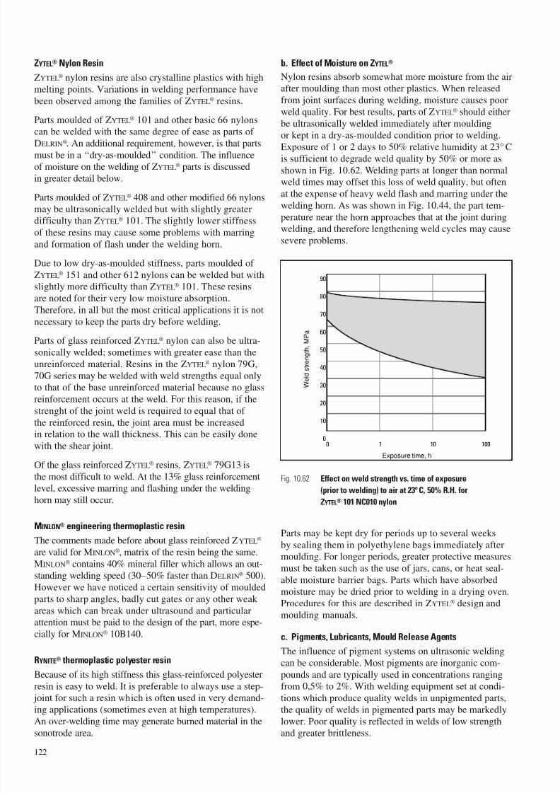
7/23/2019 f1236720 DuPont Engineering Polymers General Design Principles Module I
http://slidepdf.com/reader/full/f1236720-dupont-engineering-polymers-general-design-principles-module-i 124/155
ZYTEL® Nylon Resin
ZYTEL® nylon resins are also crystalline plastics with high
melting points. Variations in welding performance have
been observed among the families of ZYTEL® resins.
Parts moulded of ZYTEL® 101 and other basic 66 nylons
can be welded with the same degree of ease as parts of
DELRIN®. An additional requirement, however, is that parts
must be in a ‘‘dry-as-moulded’’ condition. The influenceof moisture on the welding of ZYTEL® parts is discussed
in greater detail below.
Parts moulded of ZYTEL® 408 and other modified 66 nylons
may be ultrasonically welded but with slightly greaterdifficulty than ZYTEL® 101. The slightly lower stiffness
of these resins may cause some problems with marring
and formation of flash under the welding horn.
Due to low dry-as-moulded stiffness, parts moulded of
ZYTEL®
151 and other 612 nylons can be welded but withslightly more difficulty than ZYTEL® 101. These resins
are noted for their very low moisture absorption.
Therefore, in all but the most critical applications it is not
necessary to keep the parts dry before welding.
Parts of glass reinforced ZYTEL® nylon can also be ultra-
sonically welded; sometimes with greater ease than the
unreinforced material. Resins in the ZYTEL® nylon 79G,
70G series may be welded with weld strengths equal onlyto that of the base unreinforced material because no glass
reinforcement occurs at the weld. For this reason, if the
strenght of the joint weld is required to equal that of
the reinforced resin, the joint area must be increasedin relation to the wall thickness. This can be easily done
with the shear joint.
Of the glass reinforced ZYTEL® resins, ZYTEL® 79G13 is
the most difficult to weld. At the 13% glass reinforcementlevel, excessive marring and flashing under the welding
horn may still occur.
MINLON® engineering thermoplastic resin
The comments made before about glass reinforced ZYTEL®
are valid for MINLON®
, matrix of the resin being the same.MINLON® contains 40% mineral filler which allows an out-standing welding speed (30–50% faster than DELRIN® 500).
However we have noticed a certain sensitivity of moulded
parts to sharp angles, badly cut gates or any other weak
areas which can break under ultrasound and particularattention must be paid to the design of the part, more espe-
cially for MINLON® 10B140.
RYNITE® thermoplastic polyester resin
Because of its high stiffness this glass-reinforced polyester
resin is easy to weld. It is preferable to always use a step-
joint for such a resin which is often used in very demand-ing applications (sometimes even at high temperatures).
An over-welding time may generate burned material in the
sonotrode area.
b. Effect of Moisture on ZYTEL®
Nylon resins absorb somewhat more moisture from the airafter moulding than most other plastics. When released
from joint surfaces during welding, moisture causes poor
weld quality. For best results, parts of ZYTEL® should either
be ultrasonically welded immediately after moulding
or kept in a dry-as-moulded condition prior to welding.Exposure of 1 or 2 days to 50% relative humidity at 23° C
is sufficient to degrade weld quality by 50% or more as
shown in Fig. 10.62. Welding parts at longer than normalweld times may offset this loss of weld quality, but often
at the expense of heavy weld flash and marring under the
welding horn. As was shown in Fig. 10.44, the part tem-
perature near the horn approaches that at the joint duringwelding, and therefore lengthening weld cycles may cause
severe problems.
Parts may be kept dry for periods up to several weeks
by sealing them in polyethylene bags immediately after
moulding. For longer periods, greater protective measuresmust be taken such as the use of jars, cans, or heat seal-
able moisture barrier bags. Parts which have absorbed
moisture may be dried prior to welding in a drying oven.Procedures for this are described in ZYTEL® design and
moulding manuals.
c. Pigments, Lubricants, Mould Release Agents
The influence of pigment systems on ultrasonic welding
can be considerable. Most pigments are inorganic com-
pounds and are typically used in concentrations rangingfrom 0,5% to 2%. With welding equipment set at condi-
tions which produce quality welds in unpigmented parts,the quality of welds in pigmented parts may be markedly
lower. Poor quality is reflected in welds of low strengthand greater brittleness.
122
0 1 10 100
20
10
0
50
40
30
80
70
60
90
Exposure time, h
W e l d s t r e n g t h ,
M P a
Fig. 10.62 Effect on weld strength vs. time of exposure
(prior to welding) to air at 23°C, 50% R.H. for
ZYTEL® 101 NC010 nylon
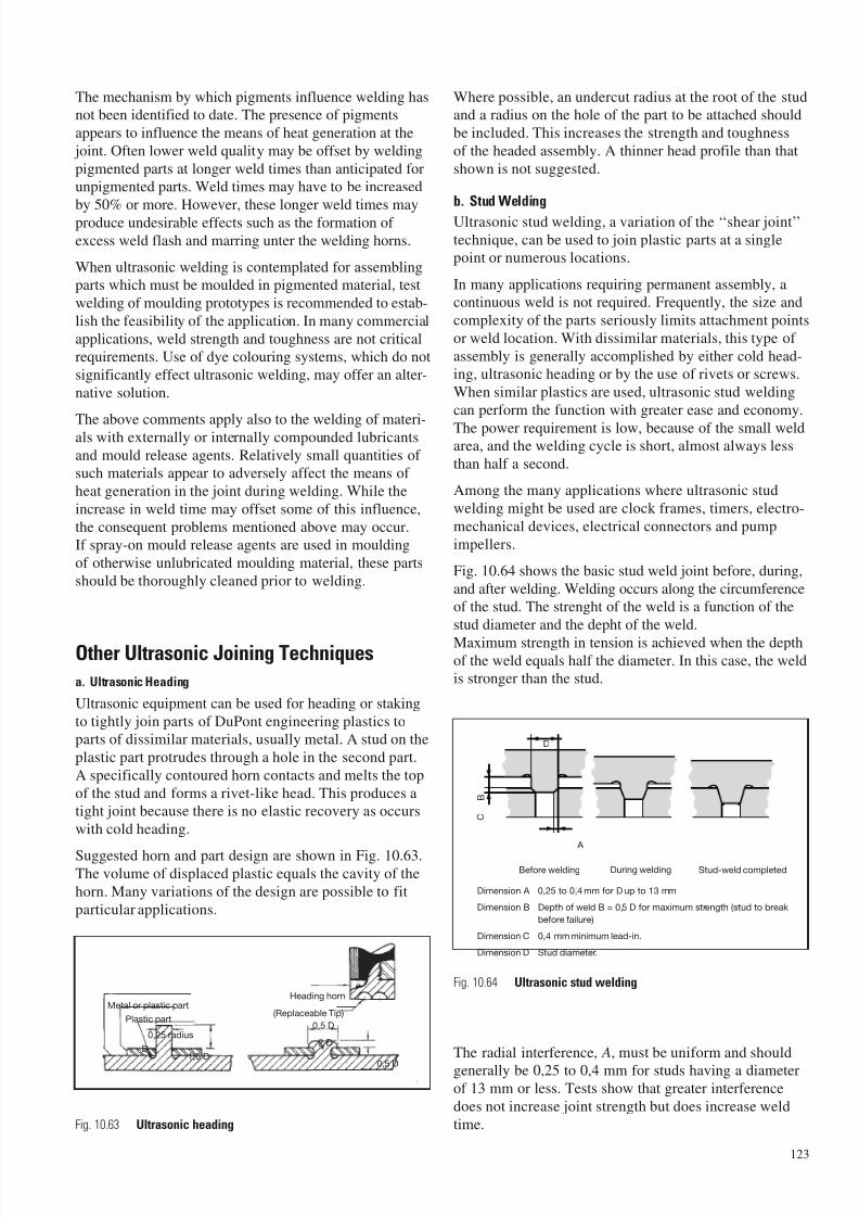
7/23/2019 f1236720 DuPont Engineering Polymers General Design Principles Module I
http://slidepdf.com/reader/full/f1236720-dupont-engineering-polymers-general-design-principles-module-i 125/155
The mechanism by which pigments influence welding hasnot been identified to date. The presence of pigments
appears to influence the means of heat generation at the
joint. Often lower weld quality may be offset by welding
pigmented parts at longer weld times than anticipated forunpigmented parts. Weld times may have to be increased
by 50% or more. However, these longer weld times may
produce undesirable effects such as the formation of
excess weld flash and marring unter the welding horns.
When ultrasonic welding is contemplated for assemblingparts which must be moulded in pigmented material, test
welding of moulding prototypes is recommended to estab-
lish the feasibility of the application. In many commercial
applications, weld strength and toughness are not criticalrequirements. Use of dye colouring systems, which do not
significantly effect ultrasonic welding, may offer an alter-
native solution.
The above comments apply also to the welding of materi-als with externally or internally compounded lubricants
and mould release agents. Relatively small quantities of such materials appear to adversely affect the means of
heat generation in the joint during welding. While the
increase in weld time may offset some of this influence,
the consequent problems mentioned above may occur.If spray-on mould release agents are used in moulding
of otherwise unlubricated moulding material, these parts
should be thoroughly cleaned prior to welding.
Other Ultrasonic Joining Techniques
a. Ultrasonic Heading
Ultrasonic equipment can be used for heading or staking
to tightly join parts of DuPont engineering plastics toparts of dissimilar materials, usually metal. A stud on the
plastic part protrudes through a hole in the second part.
A specifically contoured horn contacts and melts the top
of the stud and forms a rivet-like head. This produces atight joint because there is no elastic recovery as occurs
with cold heading.
Suggested horn and part design are shown in Fig. 10.63.The volume of displaced plastic equals the cavity of the
horn. Many variations of the design are possible to fit
particular applications.
Where possible, an undercut radius at the root of the studand a radius on the hole of the part to be attached should
be included. This increases the strength and toughness
of the headed assembly. A thinner head profile than that
shown is not suggested.
b. Stud Welding
Ultrasonic stud welding, a variation of the ‘‘shear joint’’
technique, can be used to join plastic parts at a singlepoint or numerous locations.
In many applications requiring permanent assembly, acontinuous weld is not required. Frequently, the size and
complexity of the parts seriously limits attachment points
or weld location. With dissimilar materials, this type of
assembly is generally accomplished by either cold head-ing, ultrasonic heading or by the use of rivets or screws.
When similar plastics are used, ultrasonic stud welding
can perform the function with greater ease and economy.
The power requirement is low, because of the small weldarea, and the welding cycle is short, almost always less
than half a second.
Among the many applications where ultrasonic stud
welding might be used are clock frames, timers, electro-
mechanical devices, electrical connectors and pump
impellers.
Fig. 10.64 shows the basic stud weld joint before, during,
and after welding. Welding occurs along the circumferenceof the stud. The strenght of the weld is a function of the
stud diameter and the depht of the weld.
Maximum strength in tension is achieved when the depthof the weld equals half the diameter. In this case, the weldis stronger than the stud.
The radial interference, A, must be uniform and should
generally be 0,25 to 0,4 mm for studs having a diameterof 13 mm or less. Tests show that greater interference
does not increase joint strength but does increase weld
time.
123
Metal or plastic part
Plastic part
0,25 radius
D1,6 D
2 D
0,5 D
0,5 D
Heading horn
(Replaceable Tip)
Fig. 10.63 Ultrasonic heading
Fig. 10.64 Ultrasonic stud welding
Dimension A 0,25 to 0,4 mm for D up to 13 mm
Dimension B Depth of weld B = 0,5 D for maximum strength (stud to break
before failure)
Dimension C 0,4 mm minimum lead-in.
Dimension D Stud diameter.
B
A
D
Before welding During welding Stud-weld completed
C
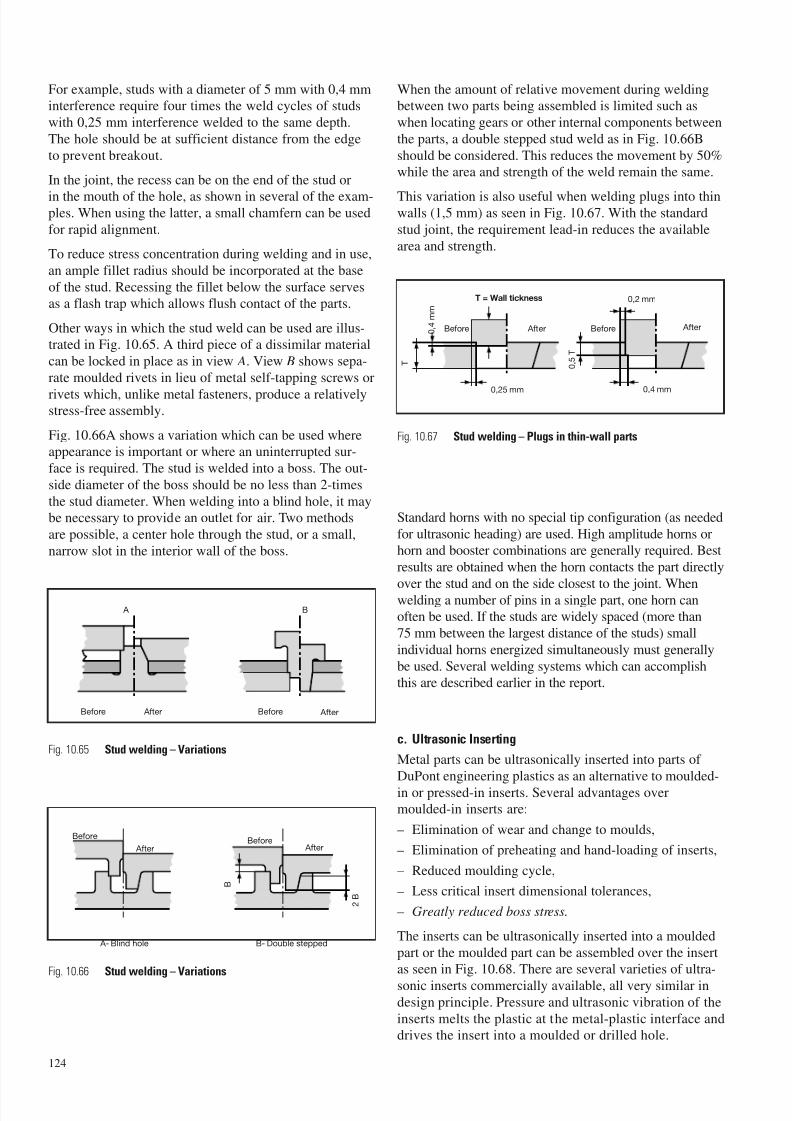
7/23/2019 f1236720 DuPont Engineering Polymers General Design Principles Module I
http://slidepdf.com/reader/full/f1236720-dupont-engineering-polymers-general-design-principles-module-i 126/155
For example, studs with a diameter of 5 mm with 0,4 mminterference require four times the weld cycles of studs
with 0,25 mm interference welded to the same depth.
The hole should be at sufficient distance from the edge
to prevent breakout.
In the joint, the recess can be on the end of the stud or
in the mouth of the hole, as shown in several of the exam-ples. When using the latter, a small chamfern can be used
for rapid alignment.
To reduce stress concentration during welding and in use,
an ample fillet radius should be incorporated at the base
of the stud. Recessing the fillet below the surface servesas a flash trap which allows flush contact of the parts.
Other ways in which the stud weld can be used are illus-trated in Fig. 10.65. A third piece of a dissimilar material
can be locked in place as in view A. View B shows sepa-
rate moulded rivets in lieu of metal self-tapping screws or
rivets which, unlike metal fasteners, produce a relativelystress-free assembly.
Fig. 10.66A shows a variation which can be used whereappearance is important or where an uninterrupted sur-
face is required. The stud is welded into a boss. The out-
side diameter of the boss should be no less than 2-times
the stud diameter. When welding into a blind hole, it maybe necessary to provide an outlet for air. Two methods
are possible, a center hole through the stud, or a small,
narrow slot in the interior wall of the boss.
When the amount of relative movement during weldingbetween two parts being assembled is limited such as
when locating gears or other internal components between
the parts, a double stepped stud weld as in Fig. 10.66B
should be considered. This reduces the movement by 50%while the area and strength of the weld remain the same.
This variation is also useful when welding plugs into thinwalls (1,5 mm) as seen in Fig. 10.67. With the standard
stud joint, the requirement lead-in reduces the available
area and strength.
Standard horns with no special tip configuration (as needed
for ultrasonic heading) are used. High amplitude horns orhorn and booster combinations are generally required. Best
results are obtained when the horn contacts the part directly
over the stud and on the side closest to the joint. Whenwelding a number of pins in a single part, one horn canoften be used. If the studs are widely spaced (more than
75 mm between the largest distance of the studs) small
individual horns energized simultaneously must generally
be used. Several welding systems which can accomplishthis are described earlier in the report.
c. Ultrasonic Inserting
Metal parts can be ultrasonically inserted into parts of
DuPont engineering plastics as an alternative to moulded-
in or pressed-in inserts. Several advantages overmoulded-in inserts are:
– Elimination of wear and change to moulds,
– Elimination of preheating and hand-loading of inserts,
– Reduced moulding cycle,
– Less critical insert dimensional tolerances,
– Greatly reduced boss stress.
The inserts can be ultrasonically inserted into a moulded
part or the moulded part can be assembled over the insertas seen in Fig. 10.68. There are several varieties of ultra-
sonic inserts commercially available, all very similar indesign principle. Pressure and ultrasonic vibration of the
inserts melts the plastic at the metal-plastic interface anddrives the insert into a moulded or drilled hole.
124
A B
Before After Before After
A- Blind hole B- Double stepped
Before
AfterBefore
After
2 B
B
Fig. 10.65 Stud welding – Variations
Fig. 10.67 Stud welding – Plugs in thin-wall parts
Fig. 10.66 Stud welding – Variations
T
0 , 4
m m
T = Wall tickness
0 , 5
T
Before After Before After
0,4 mm0,25 mm
0,2 mm
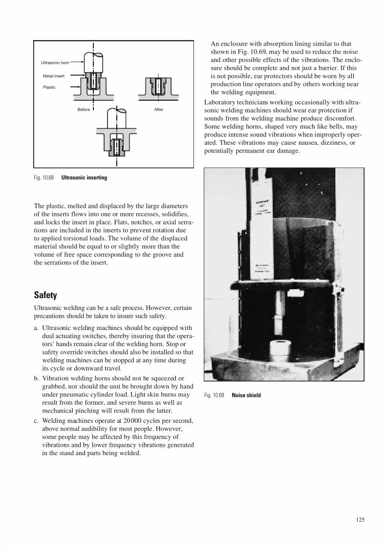
7/23/2019 f1236720 DuPont Engineering Polymers General Design Principles Module I
http://slidepdf.com/reader/full/f1236720-dupont-engineering-polymers-general-design-principles-module-i 127/155
The plastic, melted and displaced by the large diameters
of the inserts flows into one or more recesses, solidifies,
and locks the insert in place. Flats, notches, or axial serra-tions are included in the inserts to prevent rotation due
to applied torsional loads. The volume of the displaced
material should be equal to or slightly more than the
volume of free space corresponding to the groove andthe serrations of the insert.
Safety
Ultrasonic welding can be a safe process. However, certain
precautions should be taken to insure such safety.
a. Ultrasonic welding machines should be equipped with
dual actuating switches, thereby insuring that the opera-tors’ hands remain clear of the welding horn. Stop or
safety override switches should also be installed so that
welding machines can be stopped at any time during
its cycle or downward travel.
b. Vibration welding horns should not be squeezed or
grabbed, nor should the unit be brought down by handunder pneumatic cylinder load. Light skin burns mayresult from the former, and severe burns as well as
mechanical pinching will result from the latter.
c. Welding machines operate at 20000 cycles per second,above normal audibility for most people. However,
some people may be affected by this frequency of
vibrations and by lower frequency vibrations generated
in the stand and parts being welded.
An enclosure with absorption lining similar to thatshown in Fig. 10.69, may be used to reduce the noise
and other possible effects of the vibrations. The enclo-
sure should be complete and not just a barrier. If this
is not possible, ear protectors should be worn by allproduction line operators and by others working near
the welding equipment.
Laboratory technicians working occasionally with ultra-sonic welding machines should wear ear protection if
sounds from the welding machine produce discomfort.
Some welding horns, shaped very much like bells, may
produce intense sound vibrations when improperly oper-ated. These vibrations may cause nausea, dizziness, or
potentially permanent ear damage.
125
Fig. 10.68 Ultrasonic inserting
Ultrasonic horn
Metal insert
Plastic
AfterBefore
Fig. 10.69 Noise shield
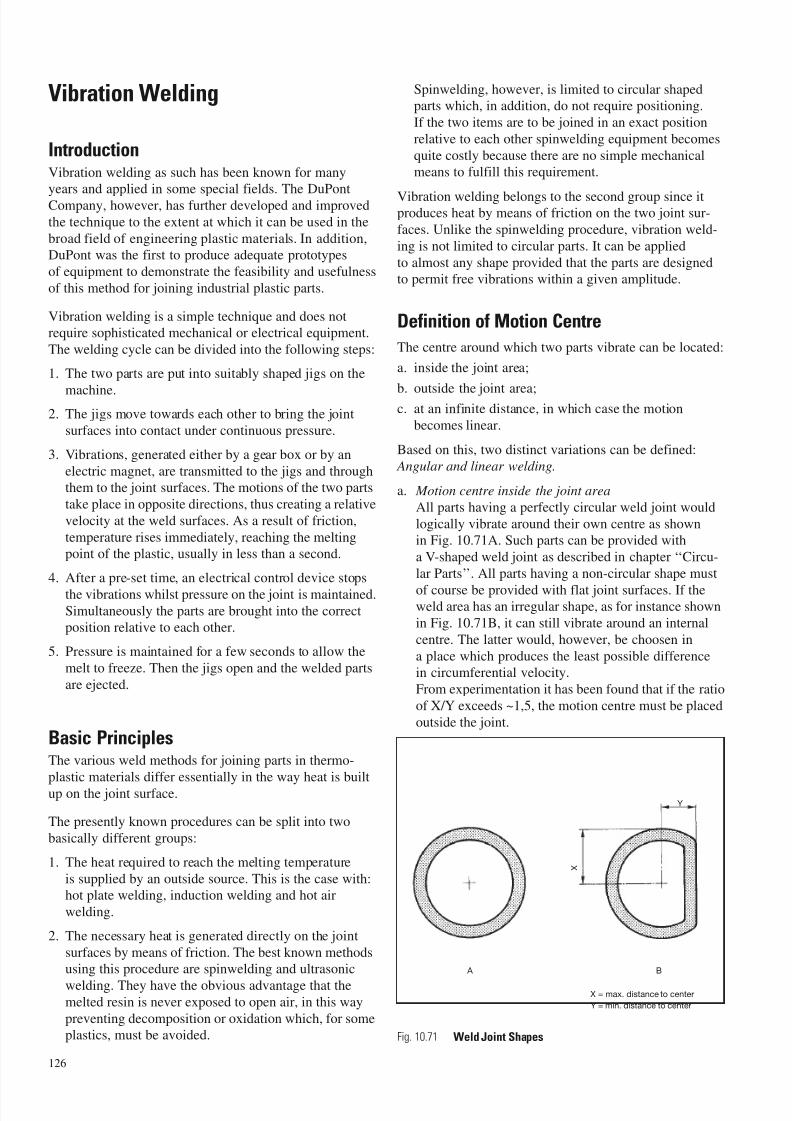
7/23/2019 f1236720 DuPont Engineering Polymers General Design Principles Module I
http://slidepdf.com/reader/full/f1236720-dupont-engineering-polymers-general-design-principles-module-i 128/155
Vibration Welding
IntroductionVibration welding as such has been known for manyyears and applied in some special fields. The DuPont
Company, however, has further developed and improved
the technique to the extent at which it can be used in the
broad field of engineering plastic materials. In addition,DuPont was the first to produce adequate prototypes
of equipment to demonstrate the feasibility and usefulness
of this method for joining industrial plastic parts.
Vibration welding is a simple technique and does notrequire sophisticated mechanical or electrical equipment.
The welding cycle can be divided into the following steps:
1. The two parts are put into suitably shaped jigs on the
machine.2. The jigs move towards each other to bring the joint
surfaces into contact under continuous pressure.
3. Vibrations, generated either by a gear box or by an
electric magnet, are transmitted to the jigs and throughthem to the joint surfaces. The motions of the two parts
take place in opposite directions, thus creating a relative
velocity at the weld surfaces. As a result of friction,
temperature rises immediately, reaching the meltingpoint of the plastic, usually in less than a second.
4. After a pre-set time, an electrical control device stops
the vibrations whilst pressure on the joint is maintained.Simultaneously the parts are brought into the correctposition relative to each other.
5. Pressure is maintained for a few seconds to allow the
melt to freeze. Then the jigs open and the welded parts
are ejected.
Basic PrinciplesThe various weld methods for joining parts in thermo-
plastic materials differ essentially in the way heat is built
up on the joint surface.
The presently known procedures can be split into two
basically different groups:
1. The heat required to reach the melting temperature
is supplied by an outside source. This is the case with:hot plate welding, induction welding and hot air
welding.
2. The necessary heat is generated directly on the joint
surfaces by means of friction. The best known methodsusing this procedure are spinwelding and ultrasonic
welding. They have the obvious advantage that themelted resin is never exposed to open air, in this way
preventing decomposition or oxidation which, for someplastics, must be avoided.
Spinwelding, however, is limited to circular shapedparts which, in addition, do not require positioning.
If the two items are to be joined in an exact position
relative to each other spinwelding equipment becomes
quite costly because there are no simple mechanicalmeans to fulfill this requirement.
Vibration welding belongs to the second group since itproduces heat by means of friction on the two joint sur-
faces. Unlike the spinwelding procedure, vibration weld-
ing is not limited to circular parts. It can be applied
to almost any shape provided that the parts are designedto permit free vibrations within a given amplitude.
Definition of Motion Centre
The centre around which two parts vibrate can be located:
a. inside the joint area;
b. outside the joint area;c. at an infinite distance, in which case the motion
becomes linear.
Based on this, two distinct variations can be defined: Angular and linear welding.
a. Motion centre inside the joint area
All parts having a perfectly circular weld joint would
logically vibrate around their own centre as shownin Fig. 10.71A. Such parts can be provided with
a V-shaped weld joint as described in chapter ‘‘Circu-
lar Parts’’. All parts having a non-circular shape must
of course be provided with flat joint surfaces. If theweld area has an irregular shape, as for instance shown
in Fig. 10.71B, it can still vibrate around an internal
centre. The latter would, however, be choosen in
a place which produces the least possible differencein circumferential velocity.
From experimentation it has been found that if the ratio
of X/Y exceeds ~1,5, the motion centre must be placed
outside the joint.
126
X
Y
A B
X = max. distance to center
Y = min. distance to center
Fig. 10.71 Weld Joint Shapes
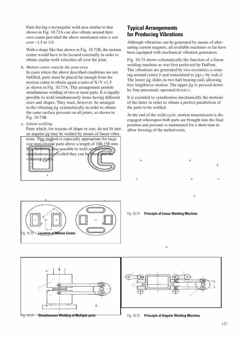
7/23/2019 f1236720 DuPont Engineering Polymers General Design Principles Module I
http://slidepdf.com/reader/full/f1236720-dupont-engineering-polymers-general-design-principles-module-i 129/155
Parts having a rectangular weld area similar to thatshown in Fig. 10.72A can also vibrate around their
own centre provided the above mentioned ratio is not
over ~1,5 to 1,0.
With a shape like that shown in Fig. 10.72B, the motion
centre would have to be located externally in order to
obtain similar weld velocities all over the joint.
b. Motion centre outside the joint area
In cases where the above described conditions are not
fulfilled, parts must be placed far enough from the
motion centre to obtain again a ratio of X/ Y <1,5
as shown in Fig. 10.73A. This arrangement permitssimultaneous welding of two or more parts. It is equally
possible to weld simultaneously items having different
sizes and shapes. They must, however, be arranged
in the vibrating jig symmetrically in order to obtainthe same surface pressure on all joints, as shown in
Fig. 10.73B.c. Linear welding
Parts which, for reasons of shape or size, do not fit into
an angular jig may be welded by means of linear vibra-
tions. This method is especially appropriate for large
size non-circular parts above a length of 100-150 mm.It is, however, also possible to weld several parts
simultaneously provided they can be fitted into the
vibrating plates.
Typical Arrangementsfor Producing Vibrations
Although vibrations can be generated by means of alter-
nating current magnets, all available machines so far have
been equipped with mechanical vibration generators.
Fig. 10.74 shows schematically the function of a linearwelding machine as was first perfected by DuPont.
The vibrations are generated by two eccentrics a rotat-ing around centre b and transmitted to jigs c by rods d .
The lower jig slides in two ball bearing rails allowing
free lengthwise motion. The upper jig is pressed down
by four pneumatic operated levers e.
It is essential to synchronize mechanically the motions
of the latter in order to obtain a perfect parallelism of the parts to be welded.
At the end of the weld cycle, motion transmission is dis-
engaged whereupon both parts are brought into the finalposition and pressure is maintained for a short time to
allow freezing of the melted resin.
127
Y
X
X
Y
+
A B
A B
Fig. 10.72 Location of Motion Centre
Fig. 10.74 Principle of Linear Welding Machine
Fig. 10.75 Principle of Angular Welding MachineFig. 10.73 Simultaneous Welding of Multiple parts
e
c
e
b
d
a
f
a
b
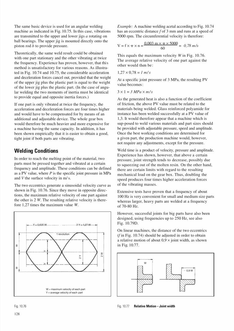
7/23/2019 f1236720 DuPont Engineering Polymers General Design Principles Module I
http://slidepdf.com/reader/full/f1236720-dupont-engineering-polymers-general-design-principles-module-i 130/155
The same basic device is used for an angular weldingmachine as indicated in Fig. 10.75. In this case, vibrations
are transmitted to the upper and lower jigs a rotating on
ball bearings. The upper jig is mounted directly onto thepiston rod b to provide pressure.
Theoretically, the same weld result could be obtained
with one part stationary and the other vibrating at twicethe frequency. Experience has proven, however, that this
method is unsatisfactory for various reasons. As illustra-
ted in Fig. 10.74 and 10.75, the considerable accelerationand deceleration forces cancel out, provided that the weight
of the upper jig plus the plastic part is equal to the weight
of the lower jig plus the plastic part. (In the case of angu-
lar welding the two moments of inertia must be identicalto provide equal and opposite inertia forces.)
If one part is only vibrated at twice the frequency, theacceleration and deceleration forces are four times higher
and would have to be compensated for by means of anadditional and adjustable device. The whole gear box
would therefore be much heavier and more expensive fora machine having the same capacity. In addition, it has
been shown empirically that it is easier to obtain a good,
tight joint if both parts are vibrating.
Welding Conditions
In order to reach the melting point of the material, two
parts must be pressed together and vibrated at a certain
frequency and amplitude. These conditions can be defined
as a PV value, where P is the specific joint pressure in MPaand V the surface velocity in m/ s.
The two eccentrics generate a sinusoidal velocity curve asshown in Fig. 10.76. Since they move in opposite direc-
tions, the maximum relative velocity of one part against
the other is 2 W . The resulting relative velocity is there-
fore 1,27 times the maximum value W .
Example: A machine welding acetal according to Fig. 10.74has an eccentric distance f of 3 mm and runs at a speed of
5000 rpm. The circumferential velocity is therefore:
V = f × × n =0,003 m × × 5000
= 0,78 m/s60
This equals the maximum velocity W in Fig. 10.76.
The average relative velocity of one part against the
other would then be:
1,27 × 0,78 = 1 m/ s
At a specific joint pressure of 3 MPa, the resulting PV
value becomes:
3 × 1 = 3 MPa × m / s
As the generated heat is also a function of the coefficient
of friction, the above PV value must be related to the
materials being welded. Glass reinforced polyamide for
instance has been welded successfully at a PV value of 1,3. It would therefore appear that a machine which is
sup-posed to weld various materials and part sizes should
be provided with adjustable pressure, speed and amplitude.
Once the best working conditions are determined fora given part, the production machine would, however,
not require any adjustments, except for the pressure.
Weld time is a product of velocity, pressure and amplitude.
Experience has shown, however, that above a certain
pressure, joint strength tends to decrease, possibly due
to squeezing out of the molten resin. On the other hand,there are certain limits with regard to the resulting
mechanical load on the gear box. Thus, doubling thespeed produces four times higher acceleration forces
of the vibrating masses.
Extensive tests have proven that a frequency of about
100 Hz is very convenient for small and medium size partswhereas larger, heavy parts are welded at a frequency
of 70-80 Hz.
However, successful joints for big parts have also been
designed, using frequencies up to 250 Hz, see also
Fig. 10.79D.
On linear machines, the distance of the two eccentrics( f in Fig. 10.74) should be adjusted in order to obtaina relative motion of about 0,9 × joint width, as shown
in Fig. 10.77.
128
Y = 0,635 W 2 Y = 1,27 W
1 revolution
W = maximum velocity of each partY = average velocity of each part
W
W
Y
Y
2 Y 2
W
Fig. 10.76
W
0,9 W
Fig. 10.77 Relative Motion – Joint width
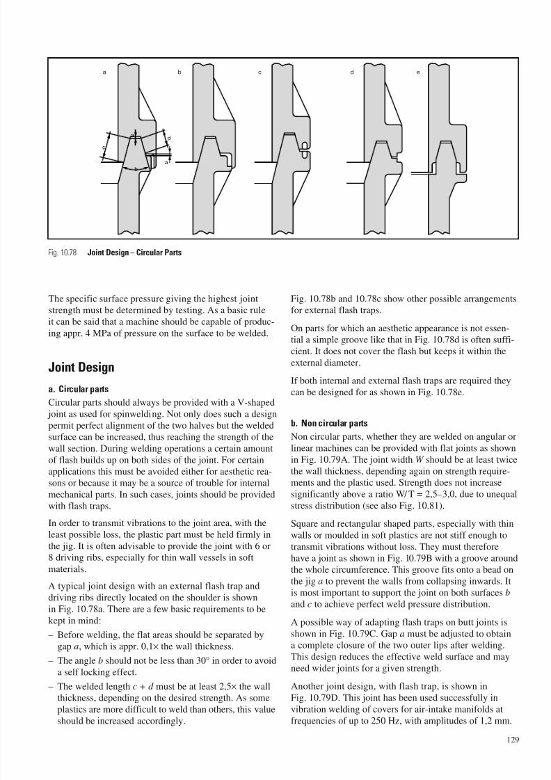
7/23/2019 f1236720 DuPont Engineering Polymers General Design Principles Module I
http://slidepdf.com/reader/full/f1236720-dupont-engineering-polymers-general-design-principles-module-i 131/155
The specific surface pressure giving the highest jointstrength must be determined by testing. As a basic rule
it can be said that a machine should be capable of produc-
ing appr. 4 MPa of pressure on the surface to be welded.
Joint Design
a. Circular parts
Circular parts should always be provided with a V-shaped
joint as used for spinwelding. Not only does such a designpermit perfect alignment of the two halves but the weldedsurface can be increased, thus reaching the strength of the
wall section. During welding operations a certain amount
of flash builds up on both sides of the joint. For certain
applications this must be avoided either for aesthetic rea-sons or because it may be a source of trouble for internal
mechanical parts. In such cases, joints should be provided
with flash traps.
In order to transmit vibrations to the joint area, with the
least possible loss, the plastic part must be held firmly in
the jig. It is often advisable to provide the joint with 6 or8 driving ribs, especially for thin wall vessels in soft
materials.
A typical joint design with an external flash trap and
driving ribs directly located on the shoulder is shown
in Fig. 10.78a. There are a few basic requirements to be
kept in mind:
– Before welding, the flat areas should be separated by
gap a, which is appr. 0,1× the wall thickness.
– The angle b should not be less than 30° in order to avoid
a self locking effect.
– The welded length c + d must be at least 2,5× the wallthickness, depending on the desired strength. As some
plastics are more difficult to weld than others, this value
should be increased accordingly.
Fig. 10.78b and 10.78c show other possible arrangementsfor external flash traps.
On parts for which an aesthetic appearance is not essen-tial a simple groove like that in Fig. 10.78d is often suffi-
cient. It does not cover the flash but keeps it within the
external diameter.
If both internal and external flash traps are required they
can be designed for as shown in Fig. 10.78e.
b. Non circular parts
Non circular parts, whether they are welded on angular or
linear machines can be provided with flat joints as shown
in Fig. 10.79A. The joint width W should be at least twice
the wall thickness, depending again on strength require-ments and the plastic used. Strength does not increase
significantly above a ratio W/ T = 2,5–3,0, due to unequal
stress distribution (see also Fig. 10.81).
Square and rectangular shaped parts, especially with thin
walls or moulded in soft plastics are not stiff enough to
transmit vibrations without loss. They must thereforehave a joint as shown in Fig. 10.79B with a groove aroundthe whole circumference. This groove fits onto a bead on
the jig a to prevent the walls from collapsing inwards. It
is most important to support the joint on both surfaces b
and c to achieve perfect weld pressure distribution.
A possible way of adapting flash traps on butt joints is
shown in Fig. 10.79C. Gap a must be adjusted to obtaina complete closure of the two outer lips after welding.
This design reduces the effective weld surface and may
need wider joints for a given strength.
Another joint design, with flash trap, is shown inFig. 10.79D. This joint has been used successfully in
vibration welding of covers for air-intake manifolds at
frequencies of up to 250 Hz, with amplitudes of 1,2 mm.
129
c
a
b
a
d
a b c d e
Fig. 10.78 Joint Design – Circular Parts
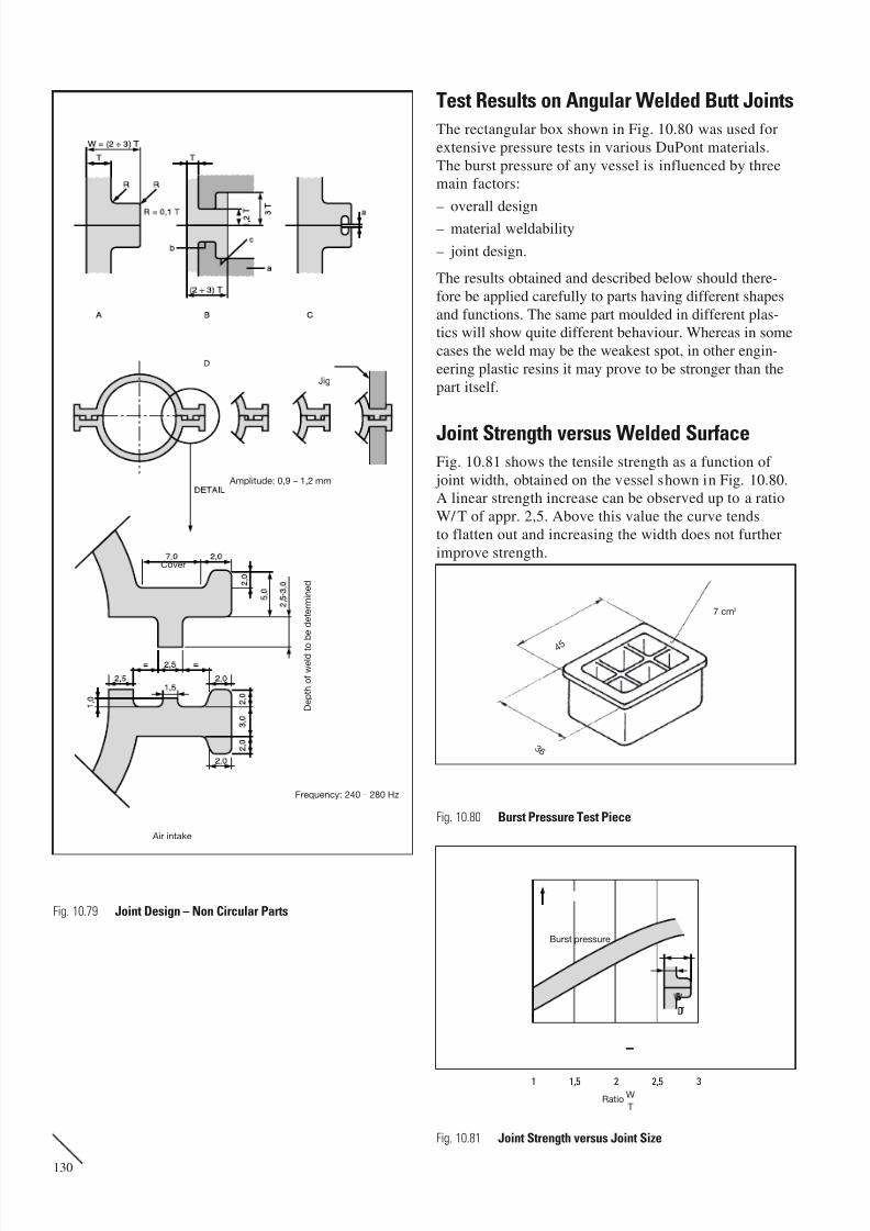
7/23/2019 f1236720 DuPont Engineering Polymers General Design Principles Module I
http://slidepdf.com/reader/full/f1236720-dupont-engineering-polymers-general-design-principles-module-i 132/155
Test Results on Angular Welded Butt Joints
The rectangular box shown in Fig. 10.80 was used for
extensive pressure tests in various DuPont materials.
The burst pressure of any vessel is influenced by threemain factors:
– overall design
– material weldability
– joint design.
The results obtained and described below should there-
fore be applied carefully to parts having different shapes
and functions. The same part moulded in different plas-tics will show quite different behaviour. Whereas in some
cases the weld may be the weakest spot, in other engin-
eering plastic resins it may prove to be stronger than the
part itself.
Joint Strength versus Welded SurfaceFig. 10.81 shows the tensile strength as a function of
joint width, obtained on the vessel shown in Fig. 10.80.A linear strength increase can be observed up to a ratio
W/ T of appr. 2,5. Above this value the curve tends
to flatten out and increasing the width does not further
improve strength.
130
Fig. 10.79 Joint Design – Non Circular Parts
1 1,5 2 2,5 3
B
D
Burst pressure
RatioW
T
7 cm2
3 6
4 5
Fig. 10.80 Burst Pressure Test Piece
Fig. 10.81 Joint Strength versus Joint Size
W
T
Jig
Amplitude: 0,9 – 1,2 mm
Frequency: 240 – 280 Hz
Cover
Air intake
D e p
t h o
f w e
l d t o
b e
d e
t e r m
i n e
d
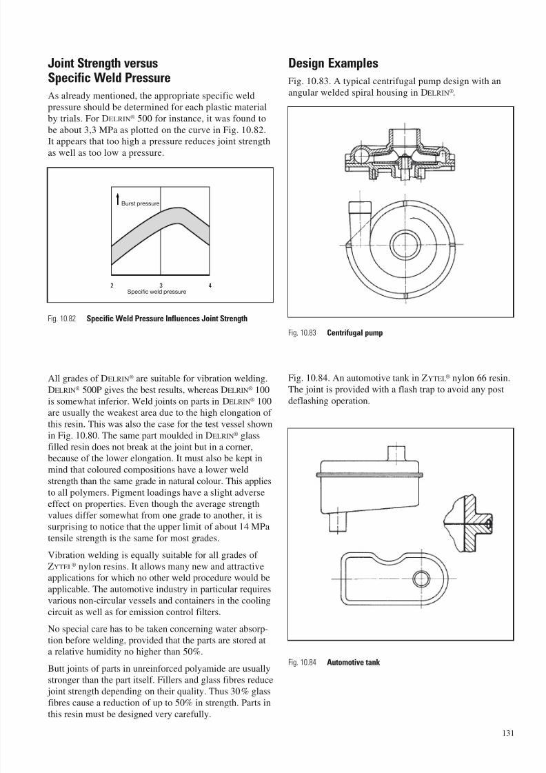
7/23/2019 f1236720 DuPont Engineering Polymers General Design Principles Module I
http://slidepdf.com/reader/full/f1236720-dupont-engineering-polymers-general-design-principles-module-i 133/155
Joint Strength versusSpecific Weld Pressure
As already mentioned, the appropriate specific weld
pressure should be determined for each plastic material
by trials. For DELRIN® 500 for instance, it was found to
be about 3,3 MPa as plotted on the curve in Fig. 10.82.It appears that too high a pressure reduces joint strength
as well as too low a pressure.
All grades of DELRIN® are suitable for vibration welding.
DELRIN® 500P gives the best results, whereas DELRIN® 100
is somewhat inferior. Weld joints on parts in DELRIN®
100are usually the weakest area due to the high elongation of
this resin. This was also the case for the test vessel shown
in Fig. 10.80. The same part moulded in DELRIN® glass
filled resin does not break at the joint but in a corner,because of the lower elongation. It must also be kept in
mind that coloured compositions have a lower weld
strength than the same grade in natural colour. This applies
to all polymers. Pigment loadings have a slight adverseeffect on properties. Even though the average strength
values differ somewhat from one grade to another, it is
surprising to notice that the upper limit of about 14 MPa
tensile strength is the same for most grades.Vibration welding is equally suitable for all grades of
ZYTEL® nylon resins. It allows many new and attractiveapplications for which no other weld procedure would be
applicable. The automotive industry in particular requires
various non-circular vessels and containers in the cooling
circuit as well as for emission control filters.
No special care has to be taken concerning water absorp-
tion before welding, provided that the parts are stored ata relative humidity no higher than 50%.
Butt joints of parts in unreinforced polyamide are usually
stronger than the part itself. Fillers and glass fibres reduce joint strength depending on their quality. Thus 30% glass
fibres cause a reduction of up to 50% in strength. Parts in
this resin must be designed very carefully.
Design Examples
Fig. 10.83. A typical centrifugal pump design with an
angular welded spiral housing in DELRIN®.
Fig. 10.84. An automotive tank in ZYTEL® nylon 66 resin.
The joint is provided with a flash trap to avoid any post
deflashing operation.
131
2 3 4
Burst pressure
Specific weld pressure
Fig. 10.82 Specific Weld Pressure Influences Joint Strength
Fig. 10.83 Centrifugal pump
Fig. 10.84 Automotive tank
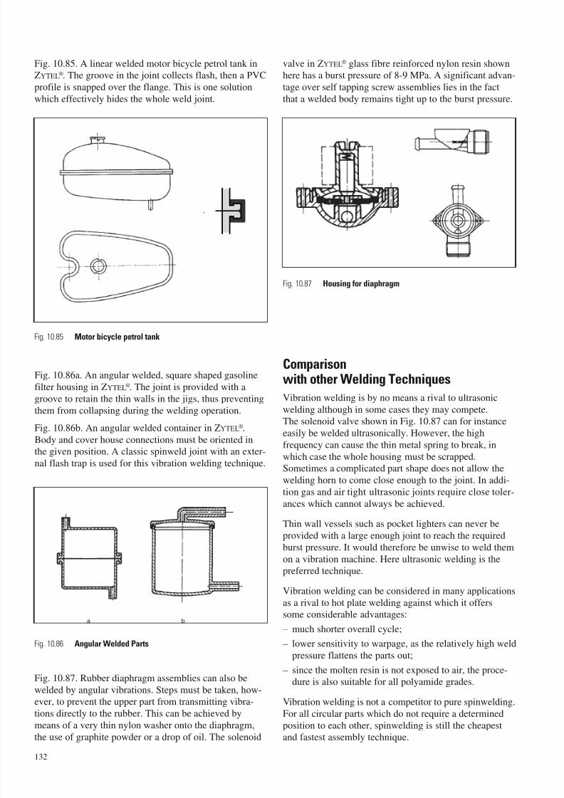
7/23/2019 f1236720 DuPont Engineering Polymers General Design Principles Module I
http://slidepdf.com/reader/full/f1236720-dupont-engineering-polymers-general-design-principles-module-i 134/155
Fig. 10.85. A linear welded motor bicycle petrol tank inZYTEL®. The groove in the joint collects flash, then a PVC
profile is snapped over the flange. This is one solution
which effectively hides the whole weld joint.
Fig. 10.86a. An angular welded, square shaped gasoline
filter housing in ZYTEL®. The joint is provided with a
groove to retain the thin walls in the jigs, thus preventing
them from collapsing during the welding operation.
Fig. 10.86b. An angular welded container in ZYTEL®.
Body and cover house connections must be oriented inthe given position. A classic spinweld joint with an exter-
nal flash trap is used for this vibration welding technique.
Fig. 10.87. Rubber diaphragm assemblies can also be
welded by angular vibrations. Steps must be taken, how-
ever, to prevent the upper part from transmitting vibra-tions directly to the rubber. This can be achieved by
means of a very thin nylon washer onto the diaphragm,
the use of graphite powder or a drop of oil. The solenoid
valve in ZYTEL® glass fibre reinforced nylon resin shownhere has a burst pressure of 8-9 MPa. A significant advan-
tage over self tapping screw assemblies lies in the fact
that a welded body remains tight up to the burst pressure.
Comparisonwith other Welding Techniques
Vibration welding is by no means a rival to ultrasonic
welding although in some cases they may compete.
The solenoid valve shown in Fig. 10.87 can for instanceeasily be welded ultrasonically. However, the high
frequency can cause the thin metal spring to break, in
which case the whole housing must be scrapped.Sometimes a complicated part shape does not allow the
welding horn to come close enough to the joint. In addi-
tion gas and air tight ultrasonic joints require close toler-
ances which cannot always be achieved.
Thin wall vessels such as pocket lighters can never be
provided with a large enough joint to reach the required
burst pressure. It would therefore be unwise to weld them
on a vibration machine. Here ultrasonic welding is thepreferred technique.
Vibration welding can be considered in many applications
as a rival to hot plate welding against which it offerssome considerable advantages:
– much shorter overall cycle;
– lower sensitivity to warpage, as the relatively high weld
pressure flattens the parts out;
– since the molten resin is not exposed to air, the proce-dure is also suitable for all polyamide grades.
Vibration welding is not a competitor to pure spinwelding.For all circular parts which do not require a determined
position to each other, spinwelding is still the cheapestand fastest assembly technique.
132
Fig. 10.87 Housing for diaphragm
Fig. 10.85 Motor bicycle petrol tank
Fig. 10.86 Angular Welded Parts
a b
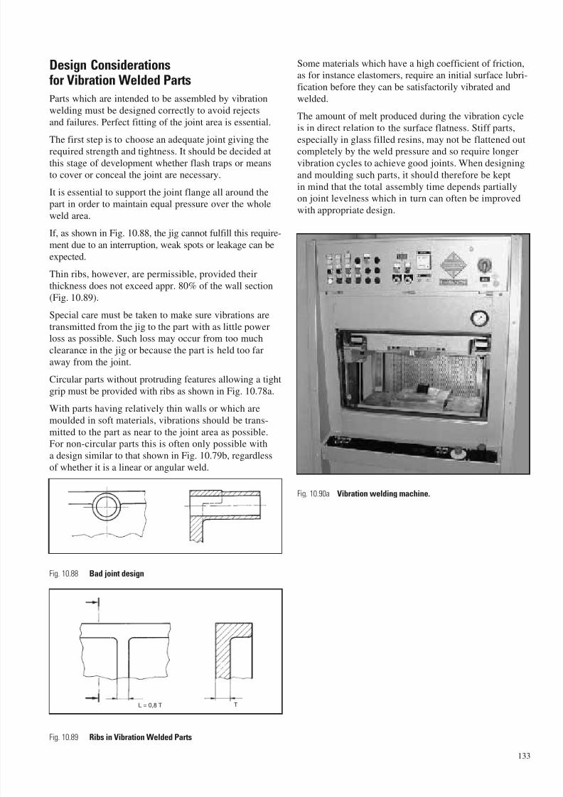
7/23/2019 f1236720 DuPont Engineering Polymers General Design Principles Module I
http://slidepdf.com/reader/full/f1236720-dupont-engineering-polymers-general-design-principles-module-i 135/155
Design Considerationsfor Vibration Welded Parts
Parts which are intended to be assembled by vibration
welding must be designed correctly to avoid rejects
and failures. Perfect fitting of the joint area is essential.
The first step is to choose an adequate joint giving therequired strength and tightness. It should be decided at
this stage of development whether flash traps or meansto cover or conceal the joint are necessary.
It is essential to support the joint flange all around thepart in order to maintain equal pressure over the whole
weld area.
If, as shown in Fig. 10.88, the jig cannot fulfill this require-
ment due to an interruption, weak spots or leakage can be
expected.
Thin ribs, however, are permissible, provided theirthickness does not exceed appr. 80% of the wall section
(Fig. 10.89).
Special care must be taken to make sure vibrations are
transmitted from the jig to the part with as little powerloss as possible. Such loss may occur from too much
clearance in the jig or because the part is held too far
away from the joint.
Circular parts without protruding features allowing a tight
grip must be provided with ribs as shown in Fig. 10.78a.
With parts having relatively thin walls or which are
moulded in soft materials, vibrations should be trans-mitted to the part as near to the joint area as possible.For non-circular parts this is often only possible with
a design similar to that shown in Fig. 10.79b, regardless
of whether it is a linear or angular weld.
Some materials which have a high coefficient of friction,as for instance elastomers, require an initial surface lubri-
fication before they can be satisfactorily vibrated and
welded.
The amount of melt produced during the vibration cycle
is in direct relation to the surface flatness. Stiff parts,
especially in glass filled resins, may not be flattened outcompletely by the weld pressure and so require longer
vibration cycles to achieve good joints. When designing
and moulding such parts, it should therefore be kept
in mind that the total assembly time depends partiallyon joint levelness which in turn can often be improved
with appropriate design.
133
L = 0,8 T T
Fig. 10.88 Bad joint design
Fig. 10.90a Vibration welding machine.
Fig. 10.89 Ribs in Vibration Welded Parts
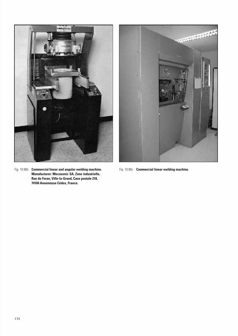
7/23/2019 f1236720 DuPont Engineering Polymers General Design Principles Module I
http://slidepdf.com/reader/full/f1236720-dupont-engineering-polymers-general-design-principles-module-i 136/155
134
Fig. 10.90b Commercial linear and angular welding machine.
Manufacturer: Mecasonic SA, Zone industrielle,
Rue de Foran, Ville-la-Grand, Case postale 218,
74104 Annemasse Cédex, France.
Fig. 10.90c Commercial linear welding machine.
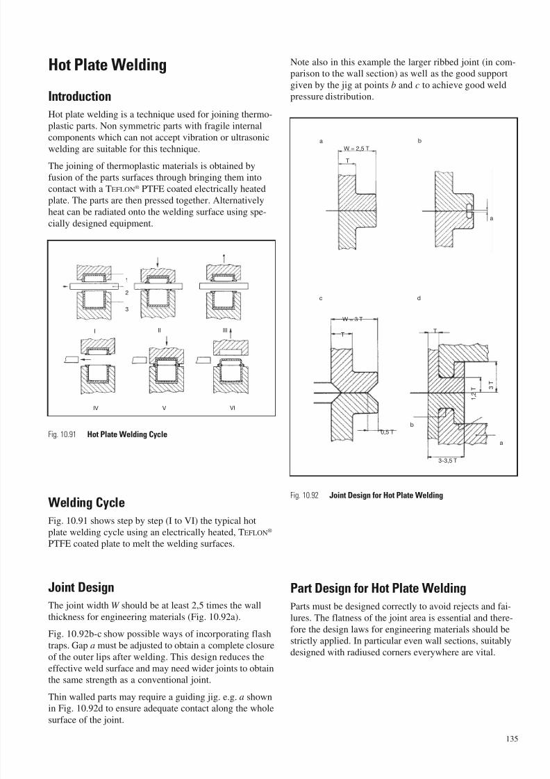
7/23/2019 f1236720 DuPont Engineering Polymers General Design Principles Module I
http://slidepdf.com/reader/full/f1236720-dupont-engineering-polymers-general-design-principles-module-i 137/155
Hot Plate Welding
Introduction
Hot plate welding is a technique used for joining thermo-
plastic parts. Non symmetric parts with fragile internal
components which can not accept vibration or ultrasonicwelding are suitable for this technique.
The joining of thermoplastic materials is obtained by
fusion of the parts surfaces through bringing them intocontact with a TEFLON® PTFE coated electrically heated
plate. The parts are then pressed together. Alternatively
heat can be radiated onto the welding surface using spe-
cially designed equipment.
Welding Cycle
Fig. 10.91 shows step by step (I to VI) the typical hot
plate welding cycle using an electrically heated, TEFLON®
PTFE coated plate to melt the welding surfaces.
Joint Design
The joint width W should be at least 2,5 times the wall
thickness for engineering materials (Fig. 10.92a).
Fig. 10.92b-c show possible ways of incorporating flash
traps. Gap a must be adjusted to obtain a complete closure
of the outer lips after welding. This design reduces the
effective weld surface and may need wider joints to obtain
the same strength as a conventional joint.Thin walled parts may require a guiding jig. e.g. a shownin Fig. 10.92d to ensure adequate contact along the whole
surface of the joint.
Note also in this example the larger ribbed joint (in com-parison to the wall section) as well as the good support
given by the jig at points b and c to achieve good weld
pressure distribution.
Part Design for Hot Plate Welding
Parts must be designed correctly to avoid rejects and fai-
lures. The flatness of the joint area is essential and there-
fore the design laws for engineering materials should bestrictly applied. In particular even wall sections, suitably
designed with radiused corners everywhere are vital.
135
I II III
IV V VI
1
2
3
Fig. 10.91 Hot Plate Welding Cycle
Fig. 10.92 Joint Design for Hot Plate Welding
a
T
W = 2,5 T
W = 3 T
T
0,5 T
T
b
3-3,5 T
a
c
1 , 2
T 3 T
a b
c d
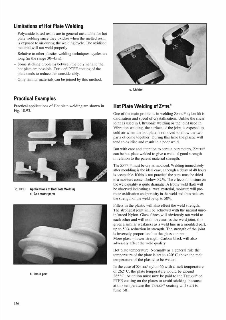
7/23/2019 f1236720 DuPont Engineering Polymers General Design Principles Module I
http://slidepdf.com/reader/full/f1236720-dupont-engineering-polymers-general-design-principles-module-i 138/155
Limitations of Hot Plate Welding
– Polyamide based resins are in general unsuitable for hot
plate welding since they oxidise when the melted resin
is exposed to air during the welding cycle. The oxidisedmaterial will not weld properly.
– Relative to other plastics welding techniques, cycles are
long (in the range 30–45 s).
– Some sticking problems between the polymer and the
hot plate are possible. TEFLON® PTFE coating of the
plate tends to reduce this considerably.
– Only similar materials can be joined by this method.
Practical Examples
Practical applications of Hot plate welding are shown in
Fig. 10.93.
Hot Plate Welding of ZYTEL®
One of the main problems in welding ZYTEL® nylon 66 isoxidisation and speed of crystallization. Unlike the shear
joint as used in Ultrasonic welding or the joint used inVibration welding, the surface of the joint is exposed to
cold air when the hot plate is removed to allow the two
parts ot come together. During this time the plastic will
tend to oxidise and result in a poor weld.
But with care and attention to certain parameters, ZYTEL®
can be hot plate welded to give a weld of good strengthin relation to the parent material strength.
The ZYTEL® must be dry as moulded. Welding immediatelyafter moulding is the ideal case, although a delay of 48 hours
is acceptable. If this is not practical the parts must be dried
to a moisture content below 0,2%. The effect of moisture on
the weld quality is quite dramatic. A frothy weld flash willbe observed indicating a “wet” material, moisture will pro-
mote oxidisation and porosity in the weld and thus reduces
the strength of the weld by up to 50%.
Fillers in the plastic will also effect the weld strength.
The strongest joint will be achieved with the natural unre-inforced Nylon. Glass fibres will obviously not weld to
each other and will not move across the weld joint, this
gives a similar weakness as a weld line in a moulded part,up to 50% reduction in strength. The strength of the jointis inversely proportional to the glass content.
More glass = lower strength. Carbon black will also
adversely affect the weld quality.
Hot plate temperature. Normally as a general rule the
temperature of the plate is set to +20° C above the melt
temperature of the plastic to be welded.
In the case of ZYTEL® nylon 66 with a melt temperature
of 262° C, the plate temperature would be around285°C. Attention must now be paid to the TEFLON® or
PTFE coating on the plates to avoid sticking, becauseat this temperature the TEFLON® coating will start to
fume off.
136
Fig. 10.93 Applications of Hot Plate Welding
a. Gas meter parts
b. Drain part
c. Lighter
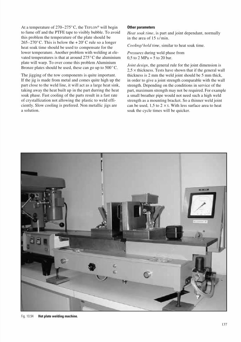
7/23/2019 f1236720 DuPont Engineering Polymers General Design Principles Module I
http://slidepdf.com/reader/full/f1236720-dupont-engineering-polymers-general-design-principles-module-i 139/155
At a temperature of 270–275° C, the TEFLON® will beginto fume off and the PTFE tape to visibly bubble. To avoid
this problem the temperature of the plate should be
265–270° C. This is below the + 20° C rule so a longer
heat soak time should be used to compensate for thelower temperature. Another problem with welding at ele-
vated temperatures is that at around 275°C the aluminium
plate will warp. To over come this problem Aluminium
Bronze plates should be used, these can go up to 500°C.
The jigging of the tow components is quite important.If the jig is made from metal and comes quite high up the
part close to the weld line, it will act as a large heat sink,
taking away the heat built up in the part durring the heat
soak phase. Fast cooling of the parts result in a fast rateof crystallization not allowing the plastic to weld effi-
ciently. Slow cooling is prefered. Non metallic jigs are
a solution.
Other parameters
Heat soak time, is part and joint dependant, normally
in the area of 15 s / min.
Cooling/ hold time, similar to heat soak time.
Pressures during weld phase from
0,5 to 2 MPa = 5 to 20 bar. Joint design, the general rule for the joint dimension is
2,5 × thickness. Tests have shown that if the general wall
thickness is 2 mm the weld joint should be 5 mm thick,in order to give a joint strength comparable with the wall
strength. Depending on the conditions in service of the
part, maximum strength may not be required. For example
a small breather pipe would not need such a high weldstrength as a mounting bracket. So a thinner weld joint
can be used, 1,5 to 2 × t. With less surface area to heat
soak the cycle times will be quicker.
137
Fig. 10.94 Hot plate welding machine.
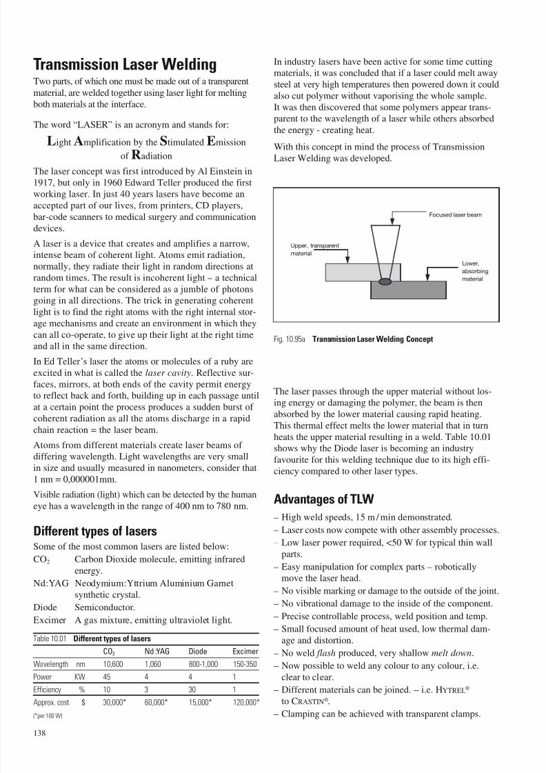
7/23/2019 f1236720 DuPont Engineering Polymers General Design Principles Module I
http://slidepdf.com/reader/full/f1236720-dupont-engineering-polymers-general-design-principles-module-i 140/155
Transmission Laser WeldingTwo parts, of which one must be made out of a transparent
material, are welded together using laser light for melting
both materials at the interface.
The word “LASER” is an acronym and stands for:
Light Amplification by the Stimulated Emission
of Radiation
The laser concept was first introduced by Al Einstein in
1917, but only in 1960 Edward Teller produced the firstworking laser. In just 40 years lasers have become an
accepted part of our lives, from printers, CD players,
bar-code scanners to medical surgery and communication
devices.
A laser is a device that creates and amplifies a narrow,intense beam of coherent light. Atoms emit radiation,
normally, they radiate their light in random directions atrandom times. The result is incoherent light – a technical
term for what can be considered as a jumble of photonsgoing in all directions. The trick in generating coherent
light is to find the right atoms with the right internal stor-
age mechanisms and create an environment in which they
can all co-operate, to give up their light at the right timeand all in the same direction.
In Ed Teller’s laser the atoms or molecules of a ruby are
excited in what is called the laser cavity. Reflective sur-
faces, mirrors, at both ends of the cavity permit energyto reflect back and forth, building up in each passage until
at a certain point the process produces a sudden burst of coherent radiation as all the atoms discharge in a rapid
chain reaction = the laser beam.
Atoms from different materials create laser beams ofdiffering wavelength. Light wavelengths are very small
in size and usually measured in nanometers, consider that
1 nm = 0,000001mm.
Visible radiation (light) which can be detected by the human
eye has a wavelength in the range of 400 nm to 780 nm.
Different types of lasersSome of the most common lasers are listed below:
CO2 Carbon Dioxide molecule, emitting infrared
energy.
Nd:YAG Neodymium:Yttrium Aluminium Garnet
synthetic crystal.
Diode Semiconductor.
Excimer A gas mixture, emitting ultraviolet light.
Table 10.01 Different types of lasers
CO2 Nd :YAG Diode Excimer
Wavelength nm 10,600 1,060 800-1,000 150-350
Power KW 45 4 4 1Efficiency % 10 3 30 1
Approx. cost $ 30,000* 60,000* 15,000* 120,000*
(*per 100 W)
In industry lasers have been active for some time cuttingmaterials, it was concluded that if a laser could melt away
steel at very high temperatures then powered down it could
also cut polymer without vaporising the whole sample.
It was then discovered that some polymers appear trans-parent to the wavelength of a laser while others absorbed
the energy - creating heat.
With this concept in mind the process of Transmission
Laser Welding was developed.
The laser passes through the upper material without los-
ing energy or damaging the polymer, the beam is thenabsorbed by the lower material causing rapid heating.
This thermal effect melts the lower material that in turn
heats the upper material resulting in a weld. Table 10.01shows why the Diode laser is becoming an industry
favourite for this welding technique due to its high effi-
ciency compared to other laser types.
Advantages of TLW
– High weld speeds, 15 m / min demonstrated.
– Laser costs now compete with other assembly processes.
– Low laser power required, <50 W for typical thin wallparts.
– Easy manipulation for complex parts – roboticallymove the laser head.
– No visible marking or damage to the outside of the joint.
– No vibrational damage to the inside of the component.
– Precise controllable process, weld position and temp.
– Small focused amount of heat used, low thermal dam-
age and distortion.
– No weld flash produced, very shallow melt down.
– Now possible to weld any colour to any colour, i.e.
clear to clear.– Different materials can be joined. – i.e. HYTREL®
to CRASTIN®.
– Clamping can be achieved with transparent clamps.
138
Fig. 10.95a Transmission Laser Welding Concept
Upper, transparent
material
Lower,
absorbingmaterial
Focused laser beam
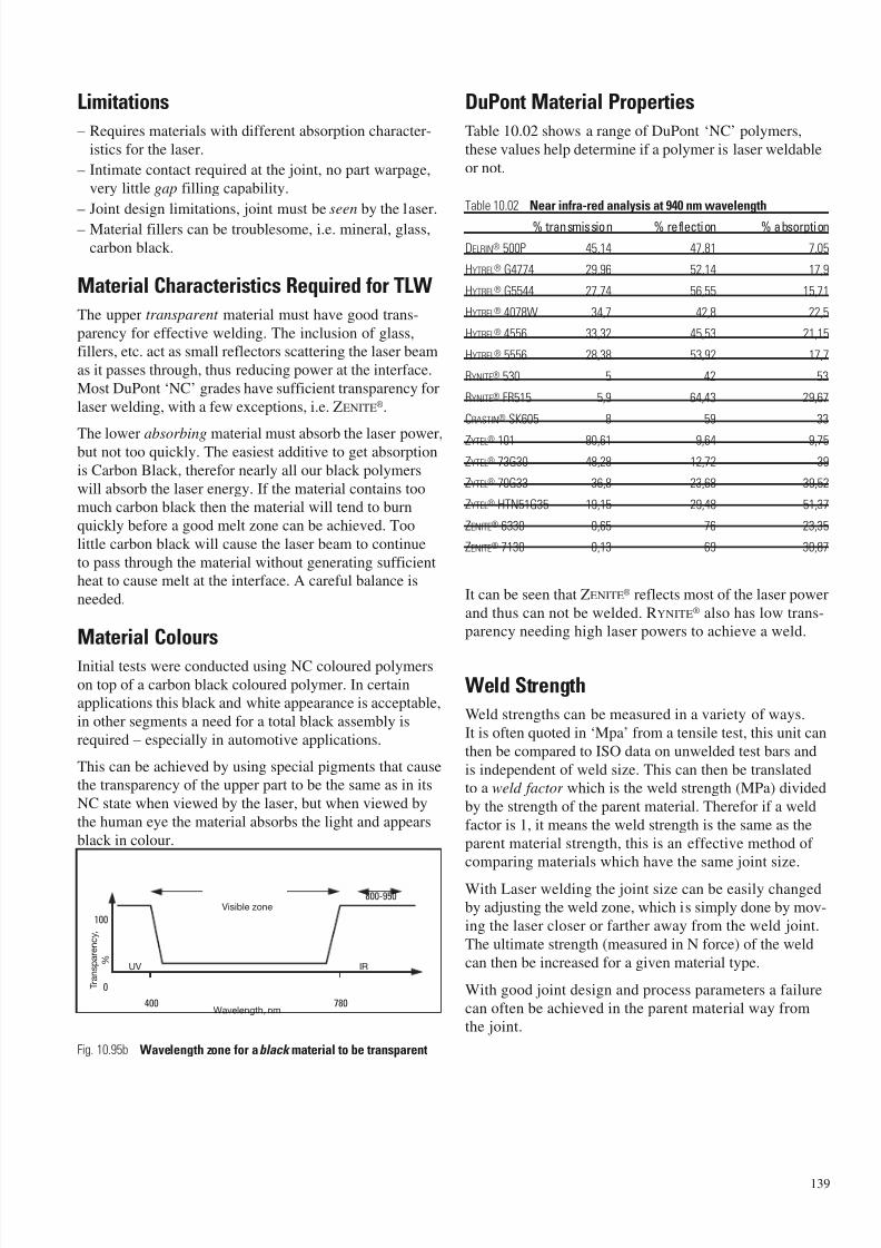
7/23/2019 f1236720 DuPont Engineering Polymers General Design Principles Module I
http://slidepdf.com/reader/full/f1236720-dupont-engineering-polymers-general-design-principles-module-i 141/155
Limitations
– Requires materials with different absorption character-
istics for the laser.
– Intimate contact required at the joint, no part warpage,
very little gap filling capability.
– Joint design limitations, joint must be seen by the laser.
– Material fillers can be troublesome, i.e. mineral, glass,
carbon black.
Material Characteristics Required for TLW
The upper transparent material must have good trans-
parency for effective welding. The inclusion of glass,fillers, etc. act as small reflectors scattering the laser beam
as it passes through, thus reducing power at the interface.
Most DuPont ‘NC’ grades have sufficient transparency for
laser welding, with a few exceptions, i.e. ZENITE®.
The lower absorbing material must absorb the laser power,but not too quickly. The easiest additive to get absorption
is Carbon Black, therefor nearly all our black polymers
will absorb the laser energy. If the material contains toomuch carbon black then the material will tend to burn
quickly before a good melt zone can be achieved. Too
little carbon black will cause the laser beam to continue
to pass through the material without generating sufficientheat to cause melt at the interface. A careful balance is
needed.
Material Colours
Initial tests were conducted using NC coloured polymers
on top of a carbon black coloured polymer. In certainapplications this black and white appearance is acceptable,
in other segments a need for a total black assembly is
required – especially in automotive applications.
This can be achieved by using special pigments that causethe transparency of the upper part to be the same as in its
NC state when viewed by the laser, but when viewed by
the human eye the material absorbs the light and appears
black in colour.
DuPont Material Properties
Table 10.02 shows a range of DuPont ‘NC’ polymers,
these values help determine if a polymer is laser weldable
or not.
Table 10.02 Near infra-red analysis at 940 nm wavelength
% transmission % reflection % absorption
DELRIN® 500P 45,14 47,81 7,05
HYTREL® G4774 29,96 52,14 17,9
HYTREL® G5544 27,74 56,55 15,71
HYTREL® 4078W 34,7 42,8 22,5
HYTREL® 4556 33,32 45,53 21,15
HYTREL® 5556 28,38 53,92 17,7
RYNITE® 530 5 42 53
RYNITE® FR515 5,9 64,43 29,67
CRASTIN® SK605 8 59 33
ZYTEL® 101 80,61 9,64 9,75
ZYTEL® 73G30 48,28 12,72 39
ZYTEL® 70G33 36,8 23,68 39,52
ZYTEL® HTN51G35 19,15 29,48 51,37
ZENITE® 6330 0,65 76 23,35
ZENITE® 7130 0,13 69 30,87
It can be seen that ZENITE® reflects most of the laser power
and thus can not be welded. RYNITE® also has low trans-parency needing high laser powers to achieve a weld.
Weld Strength
Weld strengths can be measured in a variety of ways.
It is often quoted in ‘Mpa’ from a tensile test, this unit can
then be compared to ISO data on unwelded test bars and
is independent of weld size. This can then be translatedto a weld factor which is the weld strength (MPa) divided
by the strength of the parent material. Therefor if a weld
factor is 1, it means the weld strength is the same as the
parent material strength, this is an effective method of comparing materials which have the same joint size.
With Laser welding the joint size can be easily changedby adjusting the weld zone, which is simply done by mov-
ing the laser closer or farther away from the weld joint.
The ultimate strength (measured in N force) of the weld
can then be increased for a given material type.
With good joint design and process parameters a failure
can often be achieved in the parent material way fromthe joint.
139
800-950
100
0
400 780
Fig. 10.95b Wavelength zone for ablack material to be transparent
Wavelength, nm
Visible zone
UV IR
T r a n s p a r e n c y ,
%
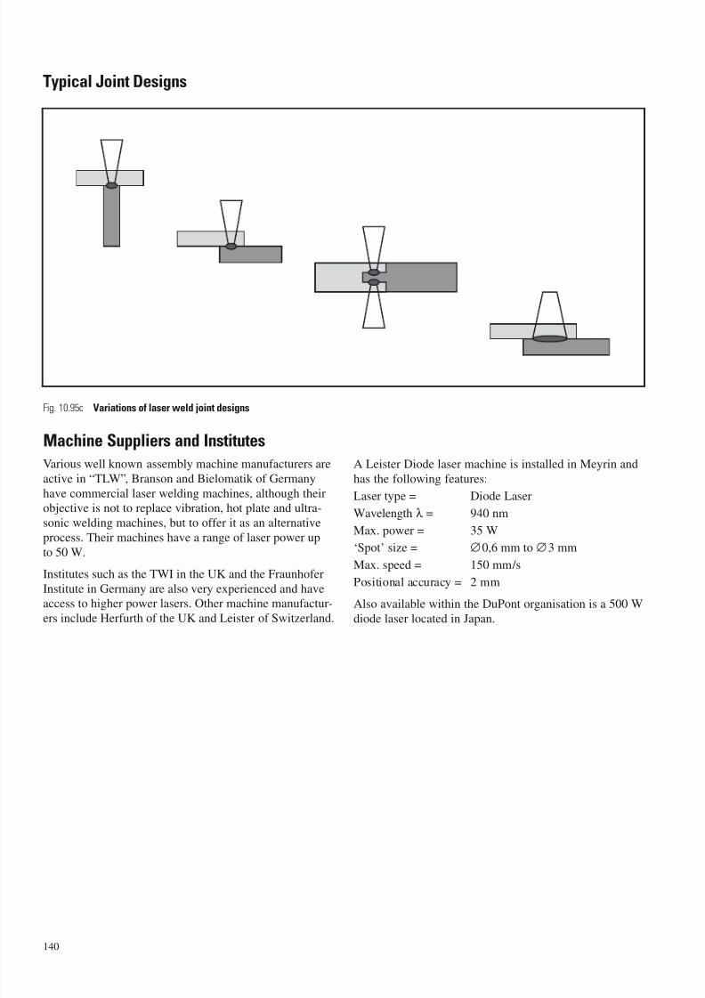
7/23/2019 f1236720 DuPont Engineering Polymers General Design Principles Module I
http://slidepdf.com/reader/full/f1236720-dupont-engineering-polymers-general-design-principles-module-i 142/155
Typical Joint Designs
Machine Suppliers and Institutes
Various well known assembly machine manufacturers are
active in “TLW”, Branson and Bielomatik of Germany
have commercial laser welding machines, although theirobjective is not to replace vibration, hot plate and ultra-
sonic welding machines, but to offer it as an alternativeprocess. Their machines have a range of laser power up
to 50 W.
Institutes such as the TWI in the UK and the Fraunhofer
Institute in Germany are also very experienced and haveaccess to higher power lasers. Other machine manufactur-
ers include Herfurth of the UK and Leister of Switzerland.
A Leister Diode laser machine is installed in Meyrin and
has the following features:
Laser type = Diode Laser
Wavelength λ = 940 nm
Max. power = 35 W
‘Spot’ size = ∅0,6 mm to ∅3 mm
Max. speed = 150 mm/s
Positional accuracy = 2 mm
Also available within the DuPont organisation is a 500 W
diode laser located in Japan.
140
Fig. 10.95c Variations of laser weld joint designs
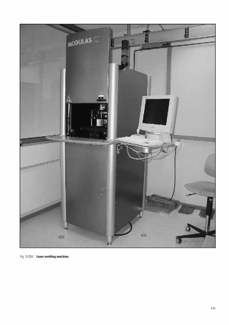
7/23/2019 f1236720 DuPont Engineering Polymers General Design Principles Module I
http://slidepdf.com/reader/full/f1236720-dupont-engineering-polymers-general-design-principles-module-i 143/155
141
Fig. 10.95d Laser welding machine.
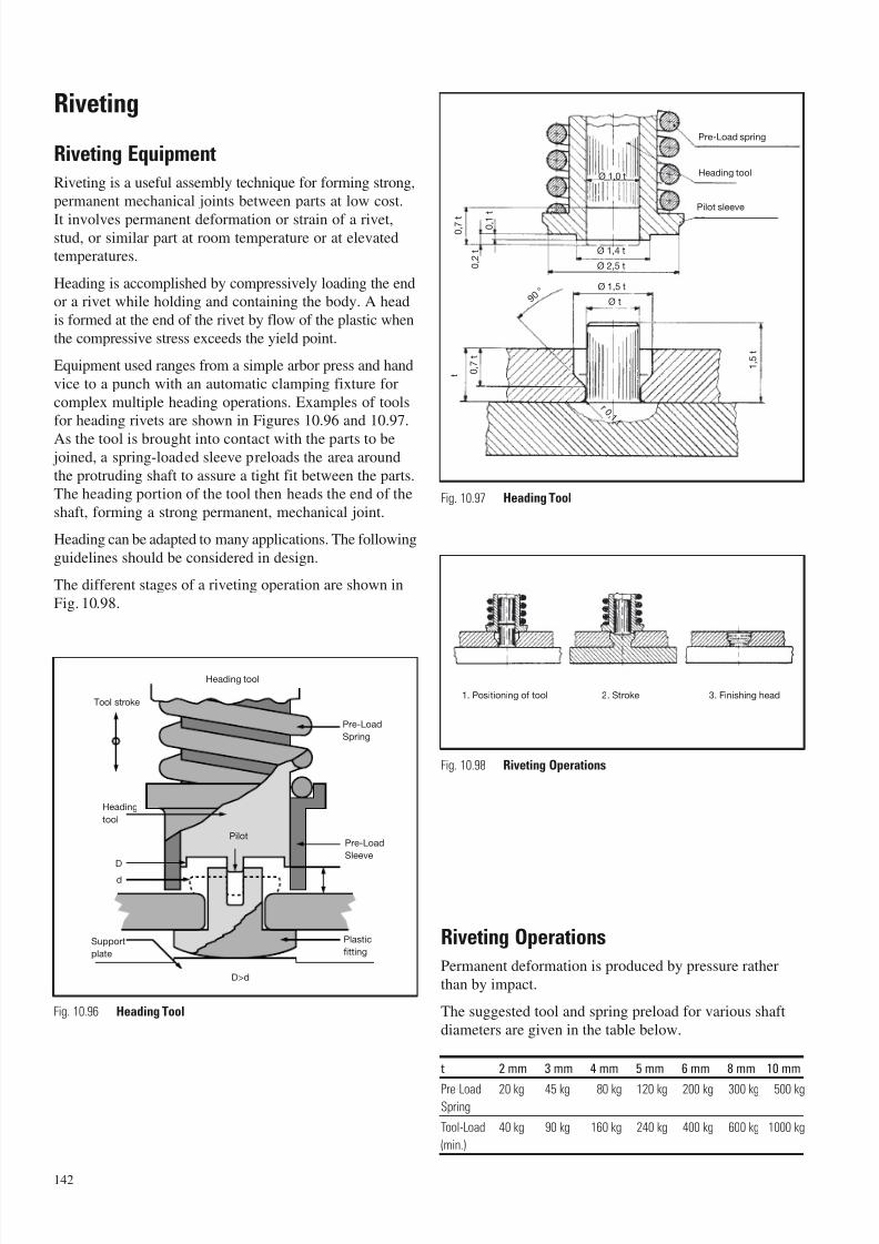
7/23/2019 f1236720 DuPont Engineering Polymers General Design Principles Module I
http://slidepdf.com/reader/full/f1236720-dupont-engineering-polymers-general-design-principles-module-i 144/155
Riveting
Riveting Equipment
Riveting is a useful assembly technique for forming strong,
permanent mechanical joints between parts at low cost.
It involves permanent deformation or strain of a rivet,stud, or similar part at room temperature or at elevatedtemperatures.
Heading is accomplished by compressively loading the endor a rivet while holding and containing the body. A head
is formed at the end of the rivet by flow of the plastic when
the compressive stress exceeds the yield point.
Equipment used ranges from a simple arbor press and hand
vice to a punch with an automatic clamping fixture for
complex multiple heading operations. Examples of toolsfor heading rivets are shown in Figures 10.96 and 10.97.
As the tool is brought into contact with the parts to be joined, a spring-loaded sleeve preloads the area around
the protruding shaft to assure a tight fit between the parts.The heading portion of the tool then heads the end of the
shaft, forming a strong permanent, mechanical joint.
Heading can be adapted to many applications. The following
guidelines should be considered in design.
The different stages of a riveting operation are shown in
Fig. 10.98.
Riveting Operations
Permanent deformation is produced by pressure rather
than by impact.
The suggested tool and spring preload for various shaft
diameters are given in the table below.
t 2 mm 3 mm 4 mm 5 mm 6 mm 8 mm 10 mm
Pre-Load 20 kg 45 kg 80 kg 120 kg 200 kg 300 kg 500 kgSpring
Tool-Load 40 kg 90 kg 160 kg 240 kg 400 kg 600 kg 1000 kg
(min.)
Heading tool
Tool stroke
Heading
tool
Pilot
Pre-Load
Spring
Pre-Load
Sleeve
Plastic
fitting
D>d
Support
plate
Pre-Load spring
Heading tool
Pilot sleeve
Ø 1,4 t
Ø 1,0 t
Ø 2,5 t
Ø 1,5 t
Ø t
0 ,
7 t
0 ,
2
t
0 , 1
t
t 0 ,
7
t
1 ,
5
t
r 0 , 1
t
9 0 °
Fig. 10.96 Heading Tool
Fig. 10.97 Heading Tool
Fig. 10.98 Riveting Operations
1. Positioning of tool 2. Stroke 3. Finishing head
142
D
d

7/23/2019 f1236720 DuPont Engineering Polymers General Design Principles Module I
http://slidepdf.com/reader/full/f1236720-dupont-engineering-polymers-general-design-principles-module-i 145/155
Relaxation of Shaft and Head
The tendency for a formed head to recover its original
shape after deformation depends upon the recovery pro-
perties of material used and on environmental temperature.
Caution
– When riveting unmodified ZYTEL® nylon it is advisable
to have the part conditioned to equilibrum moisture
content before riveting, in the dry state the materialis too brittle. Impact modified materials such as ZYTEL®
ST and ZYTEL® 408 nylon resins can be riveted in the
dry-as-moulded state.
– When riveting onto sheet-metal it is necessary to remove
all burrs from the edges of the hole in order to prevent
shearing of the head. To ensure no recovery, as normally
requested when joining sheet metal to plastic, rivetingshould be effected by ultrasonics.
143
Practical Examples
For examples of riveted parts, see Fig. 10.99.
Fig. 10.99 Applications of Riveting
b. Impeller c. Speed-reducer housing
a. Pump impeller
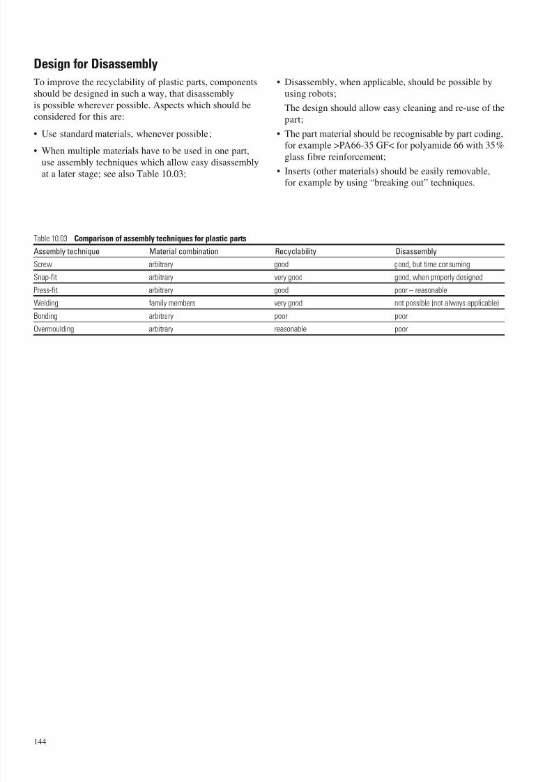
7/23/2019 f1236720 DuPont Engineering Polymers General Design Principles Module I
http://slidepdf.com/reader/full/f1236720-dupont-engineering-polymers-general-design-principles-module-i 146/155
Design for Disassembly
To improve the recyclability of plastic parts, components
should be designed in such a way, that disassembly
is possible wherever possible. Aspects which should beconsidered for this are:
• Use standard materials, whenever possible ;• When multiple materials have to be used in one part,
use assembly techniques which allow easy disassemblyat a later stage; see also Table 10.03;
• Disassembly, when applicable, should be possible by
using robots;
The design should allow easy cleaning and re-use of the
part;
• The part material should be recognisable by part coding,for example >PA66-35 GF< for polyamide 66 with 35%
glass fibre reinforcement;
• Inserts (other materials) should be easily removable,for example by using “breaking out” techniques.
144
Table 10.03 Comparison of assembly techniques for plastic parts
Assembly technique Material combination Recyclability Disassembly
Screw arbitrary good good, but time consuming
Snap-fit arbitrary very good good, when properly designed
Press-fit arbitrary good poor – reasonable
Welding family members very good not possible (not always applicable)
Bonding arbitrary poor poor
Overmoulding arbitrary reasonable poor

7/23/2019 f1236720 DuPont Engineering Polymers General Design Principles Module I
http://slidepdf.com/reader/full/f1236720-dupont-engineering-polymers-general-design-principles-module-i 147/155
Safety PrecautionsBesides the standard safety rules for mechanical operations,
machining, cutting and finishing of plastic parts, unlikemetals, can lead to local heating up to the melting point
of the plastic or even to its decomposition. It is therefore
recommended to follow similar safety work practices as
used in the production of plastic parts; namely adequate
ventilation of the working area. More detailed information
concerning the specific plastic used can be obtained from
the Safety Data Sheet of the plastic material. The waste
generated generally may not be adequate for recycling
due to its potential contamination.
Machining HYTREL
®
HYTREL® engineering thermoplastic elastomer is normally
made into useful parts by injection moulding, extruding
or melt casting. However, prototypes or small production
quantities can be machined from blocks or rods of HYTREL®.
Also, fabrication of complicated production parts can
sometimes be simplified by post-moulding machining
operation. This chapter presents some guide-lines for
machining HYTREL®.
General
Any method of machining will usually produce a matte
finish on parts of HYTREL® engineering thermoplastic elas-tomer. This finish does not affect the performance of the
part unless sliding friction is a critical factor.
Because HYTREL® is elastomeric and highly resilient, high
cutting pressure produces local deformation, which in turn
can cause part distortion. Therefore, moderate pressure
and cutting speeds should be used. Softer grades shouldbe cut with less pressure than harder ones*. Parts should
be held or supported to minimize distortion.
HYTREL® is a poor heat conductor; it does not readily
absorb heat from cutting tools, as metals do. Frictional
heat generated during machining may melt the cut surfaces.Melting can be prevented by cooling the cutting surface,either by directing a tiny jet of high pressure air at the
cutting tool or by flooding the surface with water or
a water-oil emulsion.
Some guidelines for specific machining operations follow.
Even if it is not specifically mentioned in the guidelines,
keep in mind that cooling the cut surface will alwaysimprove machining.
Turning
Standard high-speed steel tools can be used for turning
operations. Tools should be very sharp, to minimizefrictional heat. A positive rake of 10° on the tool bit is
desirable.
Cutting speeds of 2,0 to 2,5 m/s work best when no coolant
is used. Heavy cuts can be made at slower speeds, butproduce rougher finishes. Cuttings of HYTREL® cannot be
chip broken; they remain as one continuous string. When
machining soft polymers at high speeds, the cuttings maybe tacky on the surface due to frictional heat, and may
adhere to or mar the finished surface. Rough cuts produce
thicker strings which are less likely to stick to the surface.
Harder polymers are easier to cut and yield reasonablygood finishes.
Finished sizes are generally achieved by sanding withemery cloth to the desired diameter. Dimensions can
be held to 0,125 mm with the soft grades of HYTREL®,
and to 0,050 mm on the harder grades.
Long, large diameter parts can be turned satisfacorily
if the center is supported to prevent buckling.
Milling
HYTREL® has been milled successfully using a sharp, single
blade fly cutter having a 10° back rake and an end mill.With a 76 mm fly cutter, an operating speed of 10 m/s
produced good cutting action.
Blocks of HYTREL® must be secured before milling. Use
light pressure with a vise, or adhere the part to the table
with doubleface tape. Blocks less than 9,5 mm thick are
difficult to hold because of distortion.
Drilling
Parts made of HYTREL® engineering thermoplastic elas-tomer can be drilled with standard high speed twist drills.
Drill bits having an included angle of 118° have been used
satisfactorily, but lesser angles should improve drilling
ability. The drill must be very sharp to produce a clean,smooth hole.
With the hard grades of HYTREL®, good results have been
obtained at drill speeds of 500 to 3500 rev/min and cut-
ting speeds of 0,13 to 3,6 m/s. The force required to feed
the drill decreases with increasing speed. The softer grades,being more resilient, generally yield a poorer surface fin-
ish. Flooding with coolant improves the finish. However,
even when using the softest grade of HYTREL® without
coolant, no surface melting was observed at a drill speed
of 5160 rev/min with drill sizes up to 25 mm diameter.
145
11 – Machining, Cutting and Finishing
* Throughout this report, “soft grades” or “soft polymers” refers generally to the grades of HYTREL®
that have a flexural modulus below about 240 MPa while “hard grades” or “hard polymers” refers
generally to those grades whose flexural modulus is above this value. However, there is no sharp
transition point; machining conditions will vary gradually from type to type.

7/23/2019 f1236720 DuPont Engineering Polymers General Design Principles Module I
http://slidepdf.com/reader/full/f1236720-dupont-engineering-polymers-general-design-principles-module-i 148/155
Tolerances may be difficult to hold. HYTREL® has an
“elastic memory” which causes it to close in on holes that
are cut into it. As a result, finished dimensions of holes
will generally be slightly smaller than the drill size, unless
drill whip occurs. To meet exact dimensions, use slightly
oversize drills, or hone the hole to size. In test drillings,
finished hole size obtained with a 12,7 mm diameter drill
bit ranged from 12 mm – 5% undersize – at low speed
to 13 mm – 3% oversize – at high speed.
Tapping or threading
Because of the tendency of HYTREL® to close in on holes
(see Drilling), tapping threads is impossible with thesofter grades and very difficult with the harder grades.
Designs which require tapping of HYTREL® should be
avoided.
External threads can be cut using a single point tool.
However, binding and distortion are frequently encoun-
tered when threading parts of HYTREL®.
Band sawing
The following types of blades have been used satisfacto-rily to saw HYTREL® engineering thermoplastic elastomer:
– 1,6 teeth per cm, raker set;
– 1,6 teeth per cm, skip tooth, raker set;
– 4 teeth per cm, raker set.
Cutting speeds ranging from 0,7 to 30 m/s have been used.
At low speeds, cutting efficiency is reduced and morepower is required. At high speeds, less force is needed
to feed the stock. Optimum cutting speed with a 1,6-tooth
raker blade is about 18 m/s. Slight melting has been
observed when using a 4-tooth blade at 30 m/s, indicatingthat finer teeth cause more frictional heat at high speeds.
Flooding the saw blade with coolant produces a goodclean cut because little or no frictional heat is developed.
When a saw that is not equipped with coolant is used,blades that have a wide tooth set are suggested to mini-
mize frictional heat.
Cutting can be improved by wedging the cut open to
prevent binding of the blade.
146
Machining chart for HYTREL® engineering thermoplastic elastomer
Machining Types of Preferred Optimum Suggestions
Operation HYTREL® Tools Cutting Speed
Band Sawing All Grades 1,6 to 4 tooth per cm 18 m/s Wedge cut open to prevent binding.
blade, raker set Flood saw blade with coolant.
Turning All Grades Standard high-speed 2,0 to 2,5 m/s Tools should be very sharp.
(Harder grades steel tools with positive when no coolant is used Sand with emery cloth to final
are easier to work with) rake of 10° on the bit dimensions.
Milling All Grades Single blade fly cutter 10 m/s Tools should be very sharp.
having a 10° back rake Secure stock for milling.
Drilling All Grades Standard high-speed 0,13 to 3,6 m/s Use slightly over-size drills or hone
(Harder grades are twist drills for harder grades to final size.
easier to drill) Use coolant for smoother finish.
Tapping Hardest grades only – – Tapping of HYTREL®
is extremely difficult because
polymer tends to close in on holes
cut into it.Avoid designs that require tapping.
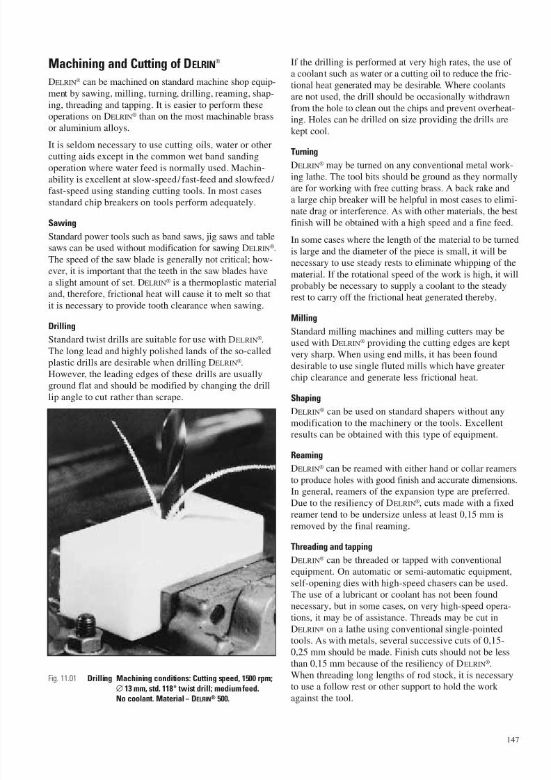
7/23/2019 f1236720 DuPont Engineering Polymers General Design Principles Module I
http://slidepdf.com/reader/full/f1236720-dupont-engineering-polymers-general-design-principles-module-i 149/155
Machining and Cutting of DELRIN®
DELRIN® can be machined on standard machine shop equip-
ment by sawing, milling, turning, drilling, reaming, shap-
ing, threading and tapping. It is easier to perform theseoperations on DELRIN® than on the most machinable brass
or aluminium alloys.
It is seldom necessary to use cutting oils, water or other
cutting aids except in the common wet band sanding
operation where water feed is normally used. Machin-
ability is excellent at slow-speed/ fast-feed and slowfeed / fast-speed using standing cutting tools. In most cases
standard chip breakers on tools perform adequately.
Sawing
Standard power tools such as band saws, jig saws and tablesaws can be used without modification for sawing DELRIN®.
The speed of the saw blade is generally not critical; how-
ever, it is important that the teeth in the saw blades havea slight amount of set. DELRIN® is a thermoplastic materialand, therefore, frictional heat will cause it to melt so that
it is necessary to provide tooth clearance when sawing.
Drilling
Standard twist drills are suitable for use with DELRIN®.
The long lead and highly polished lands of the so-called
plastic drills are desirable when drilling DELRIN®.
However, the leading edges of these drills are usuallyground flat and should be modified by changing the drill
lip angle to cut rather than scrape.
If the drilling is performed at very high rates, the use ofa coolant such as water or a cutting oil to reduce the fric-
tional heat generated may be desirable. Where coolants
are not used, the drill should be occasionally withdrawn
from the hole to clean out the chips and prevent overheat-ing. Holes can be drilled on size providing the drills are
kept cool.
Turning
DELRIN® may be turned on any conventional metal work-
ing lathe. The tool bits should be ground as they normally
are for working with free cutting brass. A back rake and
a large chip breaker will be helpful in most cases to elimi-nate drag or interference. As with other materials, the best
finish will be obtained with a high speed and a fine feed.
In some cases where the length of the material to be turned
is large and the diameter of the piece is small, it will be
necessary to use steady rests to eliminate whipping of the
material. If the rotational speed of the work is high, it willprobably be necessary to supply a coolant to the steady
rest to carry off the frictional heat generated thereby.
Milling
Standard milling machines and milling cutters may beused with DELRIN® providing the cutting edges are kept
very sharp. When using end mills, it has been found
desirable to use single fluted mills which have greater
chip clearance and generate less frictional heat.
Shaping
DELRIN® can be used on standard shapers without anymodification to the machinery or the tools. Excellent
results can be obtained with this type of equipment.
Reaming
DELRIN® can be reamed with either hand or collar reamers
to produce holes with good finish and accurate dimensions.In general, reamers of the expansion type are preferred.
Due to the resiliency of DELRIN®, cuts made with a fixed
reamer tend to be undersize unless at least 0,15 mm is
removed by the final reaming.
Threading and tappingDELRIN® can be threaded or tapped with conventional
equipment. On automatic or semi-automatic equipment,
self-opening dies with high-speed chasers can be used.The use of a lubricant or coolant has not been found
necessary, but in some cases, on very high-speed opera-
tions, it may be of assistance. Threads may be cut in
DELRIN® on a lathe using conventional single-pointedtools. As with metals, several successive cuts of 0,15-
0,25 mm should be made. Finish cuts should not be less
than 0,15 mm because of the resiliency of DELRIN®.
When threading long lengths of rod stock, it is necessary
to use a follow rest or other support to hold the work against the tool.
147
Fig. 11.01 Drilling Machining conditions: Cutting speed, 1500 rpm;∅ 13 mm, std. 118° twist drill; medium feed.No coolant. Material – DELRIN® 500.
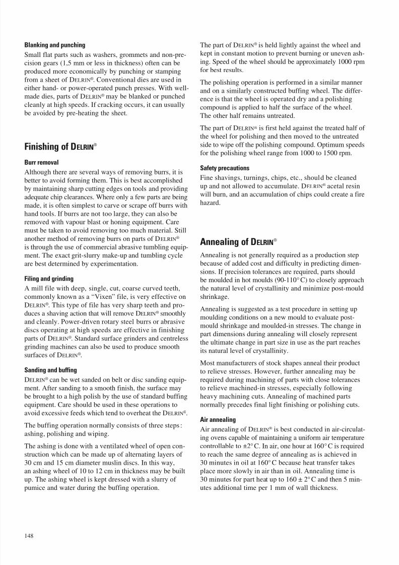
7/23/2019 f1236720 DuPont Engineering Polymers General Design Principles Module I
http://slidepdf.com/reader/full/f1236720-dupont-engineering-polymers-general-design-principles-module-i 150/155
Blanking and punching
Small flat parts such as washers, grommets and non-pre-cision gears (1,5 mm or less in thickness) often can be
produced more economically by punching or stamping
from a sheet of DELRIN®. Conventional dies are used in
either hand- or power-operated punch presses. With well-
made dies, parts of DELRIN®
may be blanked or punchedcleanly at high speeds. If cracking occurs, it can usually
be avoided by pre-heating the sheet.
Finishing of DELRIN®
Burr removal
Although there are several ways of removing burrs, it is
better to avoid forming them. This is best accomplishedby maintaining sharp cutting edges on tools and providing
adequate chip clearances. Where only a few parts are beingmade, it is often simplest to carve or scrape off burrs with
hand tools. If burrs are not too large, they can also beremoved with vapour blast or honing equipment. Care
must be taken to avoid removing too much material. Still
another method of removing burrs on parts of DELRIN®
is through the use of commercial abrasive tumbling equip-ment. The exact grit-slurry make-up and tumbling cycle
are best determined by experimentation.
Filing and grinding
A mill file with deep, single, cut, coarse curved teeth,
commonly known as a “Vixen” file, is very effective onDELRIN®. This type of file has very sharp teeth and pro-
duces a shaving action that will remove DELRIN® smoothlyand cleanly. Power-driven rotary steel burrs or abrasive
discs operating at high speeds are effective in finishing
parts of DELRIN®. Standard surface grinders and centreless
grinding machines can also be used to produce smoothsurfaces of DELRIN®.
Sanding and buffing
DELRIN® can be wet sanded on belt or disc sanding equip-
ment. After sanding to a smooth finish, the surface may
be brought to a high polish by the use of standard buffingequipment. Care should be used in these operations to
avoid excessive feeds which tend to overheat the DELRIN®.
The buffing operation normally consists of three steps :
ashing, polishing and wiping.
The ashing is done with a ventilated wheel of open con-
struction which can be made up of alternating layers of
30 cm and 15 cm diameter muslin discs. In this way,an ashing wheel of 10 to 12 cm in thickness may be built
up. The ashing wheel is kept dressed with a slurry of
pumice and water during the buffing operation.
The part of DELRIN® is held lightly against the wheel andkept in constant motion to prevent burning or uneven ash-
ing. Speed of the wheel should be approximately 1000 rpm
for best results.
The polishing operation is performed in a similar manner
and on a similarly constructed buffing wheel. The differ-
ence is that the wheel is operated dry and a polishingcompound is applied to half the surface of the wheel.
The other half remains untreated.
The part of DELRIN® is first held against the treated half of
the wheel for polishing and then moved to the untreated
side to wipe off the polishing compound. Optimum speedsfor the polishing wheel range from 1000 to 1500 rpm.
Safety precautions
Fine shavings, turnings, chips, etc., should be cleaned
up and not allowed to accumulate. DELRIN® acetal resin
will burn, and an accumulation of chips could create a firehazard.
Annealing of DELRIN®
Annealing is not generally required as a production step
because of added cost and difficulty in predicting dimen-
sions. If precision tolerances are required, parts shouldbe moulded in hot moulds (90-110°C) to closely approach
the natural level of crystallinity and minimize post-mould
shrinkage.
Annealing is suggested as a test procedure in setting up
moulding conditions on a new mould to evaluate post-
mould shrinkage and moulded-in stresses. The change inpart dimensions during annealing will closely represent
the ultimate change in part size in use as the part reaches
its natural level of crystallinity.
Most manufacturers of stock shapes anneal their product
to relieve stresses. However, further annealing may be
required during machining of parts with close tolerancesto relieve machined-in stresses, especially following
heavy machining cuts. Annealing of machined partsnormally precedes final light finishing or polishing cuts.
Air annealing
Air annealing of DELRIN® is best conducted in air-circulat-
ing ovens capable of maintaining a uniform air temperature
controllable to ±2°C. In air, one hour at 160°C is required
to reach the same degree of annealing as is achieved in30 minutes in oil at 160° C because heat transfer takes
place more slowly in air than in oil. Annealing time is
30 minutes for part heat up to 160 ± 2°C and then 5 min-
utes additional time per 1 mm of wall thickness.
148
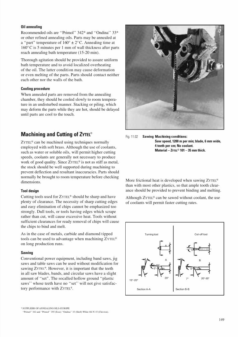
7/23/2019 f1236720 DuPont Engineering Polymers General Design Principles Module I
http://slidepdf.com/reader/full/f1236720-dupont-engineering-polymers-general-design-principles-module-i 151/155
Oil annealing
Recommended oils are ‘‘Primol’’ 342* and ‘‘Ondina’’ 33*
or other refined annealing oils. Parts may be annealed at
a ‘‘part’’ temperature of 160° ± 2°C. Annealing time at
160°C is 5 minutes per 1 mm of wall thickness after parts
reach annealing bath temperature (15-20 min).
Thorough agitation should be provided to assure uniformbath temperature and to avoid localized overheating
of the oil. The latter condition may cause deformation
or even melting of the parts. Parts should contact neither
each other nor the walls of the bath.
Cooling procedure
When annealed parts are removed from the annealing
chamber, they should be cooled slowly to room tempera-
ture in an undisturbed manner. Stacking or piling, which
may deform the parts while they are hot, should be delayeduntil parts are cool to the touch.
Machining and Cutting of ZYTEL®
ZYTEL® can be machined using techniques normally
employed with soft brass. Although the use of coolants,
such as water or soluble oils, will permit higher cuttingspeeds, coolants are generally not necessary to produce
work of good quality. Since ZYTEL® is not as stiff as metal,
the stock should be well supported during machining toprevent deflection and resultant inaccuracies. Parts should
normally be brought to room temperature before checkingdimensions.
Tool design
Cutting tools used for ZYTEL® should be sharp and have
plenty of clearance. The necessity of sharp cutting edges
and easy elimination of chips cannot be emphasized too
strongly. Dull tools, or tools having edges which scraperather than cut, will cause excessive heat. Tools without
sufficient clearances for ready removal of chips will cause
the chips to bind and melt.
As in the case of metals, carbide and diamond tipped
tools can be used to advantage when machining ZYTEL®
on long production runs.
Sawing
Conventional power equipment, including band saws, jig
saws and table saws can be used without modification for
sawing ZYTEL®. However, it is important that the teethin all saw blades, bands, and circular saws have a slight
amount of ‘‘set’’. The socalled hollow ground ‘‘plastic
saws’’ whose teeth have no ‘‘set’’ will not give satisfac-
tory performance with ZYTEL®.
* SUPPLIERS OF ANNEALING OILS-EUROPE
‘‘Primol’’ 342 and ‘‘Primol’’ 355 (Esso) ‘‘Ondina’’ 33 (Shell) White Oil N 15 (Chevron).
More frictional heat is developed when sawing ZYTEL®
than with most other plastics, so that ample tooth clear-
ance should be provided to prevent binding and melting.
Although ZYTEL® can be sawed without coolant, the use
of coolants will permit faster cutting rates.
149
Fig. 11.02 Sawing Machining conditions:
Saw speed, 1200 m per min; blade, 6 mm wide,
4 teeth per cm; No coolant.
Material – ZYTEL® 101 – 35 mm thick.
Section A-A Section B-B
20°15°-20°
0°-5° pos.
15°-20°
A
A
Turning tool Cut-off tool
5°B
B
7°0°-5° pos.
20°-30°7°

7/23/2019 f1236720 DuPont Engineering Polymers General Design Principles Module I
http://slidepdf.com/reader/full/f1236720-dupont-engineering-polymers-general-design-principles-module-i 152/155
Drilling
ZYTEL® can be drilled satisfactorily with conventionaltwist drills. The included point angle should be 118° with
10°–15° lip clearance angles. So-called ‘‘plastic drills’’ or
‘‘brass drills’’ will not perform satisfactorily with ZYTEL®.
Such drills have their leading edge ground flat in order to
obtain a ‘‘scraping’’ action. In ZYTEL®
this results in over-heating and possible seizing. However, the long lead and
highly polished lands of the ‘‘plastic drills’’ permit chips
to readily flow from deep holes. This is a very desirablefeature when drilling ZYTEL®. By modifying the drill lip
angle to cut rather than scrape, these drills will work very
well on ZYTEL®. Heavy feeds should be used, consistent
with desired finish, to prevent excessive heat resultingfrom scraping rather than cutting.
Coolants should be used where possible when drilling
ZYTEL®. Where coolants are not used, the drill should be
frequently withdrawn from the hole to clean out the chipsand prevent overheating. Holes can be drilled on size
providing the drills are kept cool.
Reaming
ZYTEL® can be reamed with conventional types of reamers
to produce holes with good finish and accurate dimension.
Reamers of the expansion type are preferred. Because of
the resiliency of ZYTEL®, cuts made with a fixed reamertend to be undersize. It is difficult to remove less than
0,05 mm when reaming ZYTEL®. Although the reamer will
pass through the hole, no stock will be removed, and the
hole will remain at the original dimension after the reameris removed. At least 0,15 mm should be removed by the
final reaming if a hole of correct size is to be produced.
Threading and tapping
ZYTEL® can be threaded or tapped with conventional
equipment. Though desirable, the use of a lubricant or
coolant when threading or tapping ZYTEL® is not always
necessary.
Threads may be cut in ZYTEL® on a lathe using conven-
tional single-pointed tools. As with metals, several suc-cessive cuts of 0,15-0,25 mm should be made. The finish
cut should not be less than 0,15 mm, because of the
resiliency of the material. When threading long lengths
of rock stock, it is necessary to use a follow rest or othersupport to hold the work against the tool.
In production tapping, it is freqently desirable to use a tap
0,15 mm oversize unless a self-locking thread is desired.
Turning
ZYTEL® can be turned easily on any standard or automaticmetal working lathe. No special precautions need be
observed, although, as in other machining operations, tools
should be very sharp. Tool bits should be ground as for
soft brass; with a back rake to give free removal of thecontinuous chip, and with a large clearance to eliminate
drag or interference. Chip breakers are not generally
effective with ZYTEL® because of its toughness. A pick-off
can be used as an aid in separating the turnings wheredesired. As with other materials, the best finish will be
obtained with a high speed and fine feed.
150
Fig. 11.03 Drilling Machining conditions:
Drill size, 10 mm;
Speed 1000 rpm; No coolant.
Material – ZYTEL® 101 – 35 mm thick.Fig. 11.04 Turning Machining conditions:
Lathe speed, 980 rpm;
cutting speed 185 m/min; feed 0,15 mm;depth of cut, 2,5 mm; No coolant.
Material – ZYTEL® 101 – 60 mm diameter.

7/23/2019 f1236720 DuPont Engineering Polymers General Design Principles Module I
http://slidepdf.com/reader/full/f1236720-dupont-engineering-polymers-general-design-principles-module-i 153/155
Milling
ZYTEL® can be readily milled using conventional cuttersproviding the cutting edges are kept very sharp.
Where possible, climb milling should be used to minimize
burring the ZYTEL®. Cutting speeds in excess of 300 m/min
and heavy feeds in excess of 230 mm/min have been used
successfully.
Blanking and punching
Small flat parts such as washers, grommets and non-pre-
cision gears, 2 mm or less in thickness, often can be pro-
duced more economically by punching or stamping froman extruded ZYTEL® strip than by injection moulding.
Conventional dies are used in either hand or power op-
erated punch presses.
With well-made dies, ZYTEL® may be blanked or punched
cleanly at high speed. If cracking occurs, it can usually beovercome by preheating the strip or by soaking it in wateruntil approximately two percent moisture has been
absorbed.
Finishing of ZYTEL®
Burr removal
Some machining operations tend to create burrs on the
part. Although there are a number of ways to remove
burrs, it is better to avoid forming them. This is best
accomplished by maintaining sharp cutting edges and
providing plenty of chip clearances.
Where only a few parts are being made, it is often simplestto carve or scrape off the burrs with hand tools.
If the burrs are not too large, they can be successfullyremoved by singeing or melting. In singeing, the burrs are
burned off by playing an alcohol flame across the part.
The burrs can be melted by directing hot nitrogen gas
290° C briefly across the part surface. The part should beexposed to the flame or gas very briefly so as not to affect
the dimension of the part.
Fine burrs can also be removed with vapour blast or hon-ing equipment. Where dimensions are critical, care shouldbe taken to avoid removing too much material.
Commercial abrasive tumbling equipment is also used for
deburring parts of ZYTEL® but the tumbling cycle is nor-mally much longer than with metal parts. Although the
exact grit slurry make-up for a particular part can best be
determined by experimenting. The grit content by volume
is usually twice the volume of parts of ZYTEL®.A detergent is also added to the watergrit mixture to
prevent the parts from being discoloured by the grit.
Filing and grindingBecause of the toughness and abrasion-resistance of
ZYTEL® nylon resins, conventional files are not satisfac-tory. However, power-driven rotary steel burrs operating
at high speeds are effective. Abrasive discs used on a
flexible shaft or on a high-speed hand grinder will remove
stock from ZYTEL® parts quickly and efficiently. Use ofa coolant is generally desired for this type of operation.
A mill file with deep, single-cut, coarse, curved teeth
(commonly known as a “Vixen” file), as is used for
aluminium and other soft metals, is very effective on
ZYTEL®
. This type of file has very sharp teeth andproduces a shaving action that will remove ZYTEL®
smoothly and cleanly.
Sanding and buffing
ZYTEL® can be wet sanded on belt or disc sanding equip-
ment. After sanding to a smooth finish, the surface may
be brought to a high polish by use of standard buffingequipment. The buffing operation is normally considered
as three steps: ashing, polishing and wiping.
Ashing is done with a ventilated wheel of open construc-
tion, made up of alternating layers of say 200 and 460 mm
diameter muslin discs. In this way, an ashing wheel of some100 to 130 mm in width may be built up. The ashing wheel
is kept dressed with a slurry of pumice and water during
the buffing operation.
151
Fig. 11.05 Milling Machining conditions:
Cutting speed, 250 m/ min; 100 mm cutter;
2,5 mm spindle; feed 150 mm/ min.
Depth of cut, 0,25 mm; No coolant.
Material – ZYTEL® 101.
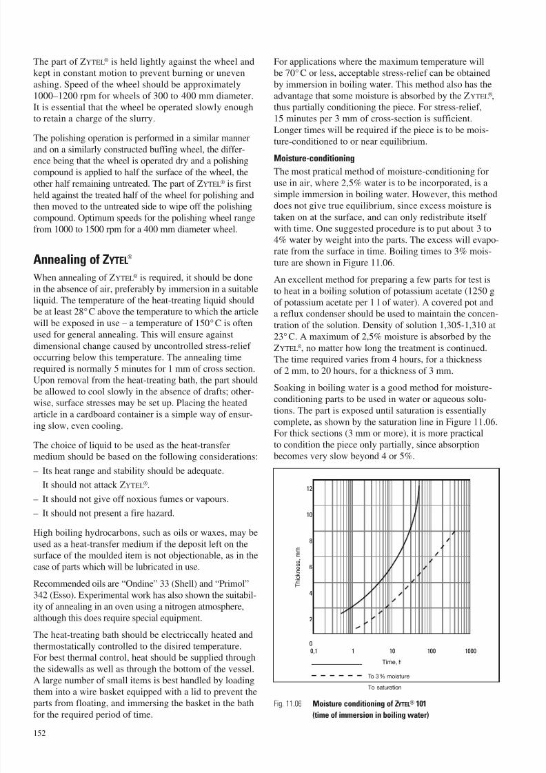
7/23/2019 f1236720 DuPont Engineering Polymers General Design Principles Module I
http://slidepdf.com/reader/full/f1236720-dupont-engineering-polymers-general-design-principles-module-i 154/155
The part of ZYTEL® is held lightly against the wheel andkept in constant motion to prevent burning or uneven
ashing. Speed of the wheel should be approximately
1000–1200 rpm for wheels of 300 to 400 mm diameter.
It is essential that the wheel be operated slowly enoughto retain a charge of the slurry.
The polishing operation is performed in a similar mannerand on a similarly constructed buffing wheel, the differ-ence being that the wheel is operated dry and a polishing
compound is applied to half the surface of the wheel, the
other half remaining untreated. The part of ZYTEL® is first
held against the treated half of the wheel for polishing andthen moved to the untreated side to wipe off the polishing
compound. Optimum speeds for the polishing wheel range
from 1000 to 1500 rpm for a 400 mm diameter wheel.
Annealing of ZYTEL®
When annealing of ZYTEL® is required, it should be done
in the absence of air, preferably by immersion in a suitable
liquid. The temperature of the heat-treating liquid shouldbe at least 28°C above the temperature to which the article
will be exposed in use – a temperature of 150°C is often
used for general annealing. This will ensure against
dimensional change caused by uncontrolled stress-relief occurring below this temperature. The annealing time
required is normally 5 minutes for 1 mm of cross section.
Upon removal from the heat-treating bath, the part should
be allowed to cool slowly in the absence of drafts; other-
wise, surface stresses may be set up. Placing the heatedarticle in a cardboard container is a simple way of ensur-
ing slow, even cooling.
The choice of liquid to be used as the heat-transfermedium should be based on the following considerations:
– Its heat range and stability should be adequate.
– It should not attack ZYTEL®.
– It should not give off noxious fumes or vapours.
– It should not present a fire hazard.
High boiling hydrocarbons, such as oils or waxes, may be
used as a heat-transfer medium if the deposit left on thesurface of the moulded item is not objectionable, as in the
case of parts which will be lubricated in use.
Recommended oils are “Ondine” 33 (Shell) and “Primol”342 (Esso). Experimental work has also shown the suitabil-
ity of annealing in an oven using a nitrogen atmosphere,
although this does require special equipment.
The heat-treating bath should be electriccally heated and
thermostatically controlled to the disired temperature.For best thermal control, heat should be supplied through
the sidewalls as well as through the bottom of the vessel.
A large number of small items is best handled by loadingthem into a wire basket equipped with a lid to prevent theparts from floating, and immersing the basket in the bath
for the required period of time.
For applications where the maximum temperature willbe 70° C or less, acceptable stress-relief can be obtained
by immersion in boiling water. This method also has the
advantage that some moisture is absorbed by the ZYTEL®,thus partially conditioning the piece. For stress-relief,
15 minutes per 3 mm of cross-section is sufficient.
Longer times will be required if the piece is to be mois-
ture-conditioned to or near equilibrium.
Moisture-conditioning
The most pratical method of moisture-conditioning for
use in air, where 2,5% water is to be incorporated, is asimple immersion in boiling water. However, this method
does not give true equilibrium, since excess moisture is
taken on at the surface, and can only redistribute itself
with time. One suggested procedure is to put about 3 to4% water by weight into the parts. The excess will evapo-
rate from the surface in time. Boiling times to 3% mois-
ture are shown in Figure 11.06.
An excellent method for preparing a few parts for test is
to heat in a boiling solution of potassium acetate (1250 g
of potassium acetate per 1 l of water). A covered pot anda reflux condenser should be used to maintain the concen-
tration of the solution. Density of solution 1,305-1,310 at
23°C. A maximum of 2,5% moisture is absorbed by the
ZYTEL®, no matter how long the treatment is continued.The time required varies from 4 hours, for a thickness
of 2 mm, to 20 hours, for a thickness of 3 mm.
Soaking in boiling water is a good method for moisture-
conditioning parts to be used in water or aqueous solu-
tions. The part is exposed until saturation is essentially
complete, as shown by the saturation line in Figure 11.06.For thick sections (3 mm or more), it is more practical
to condition the piece only partially, since absorption
becomes very slow beyond 4 or 5%.
152
10 100 100010,1
4
0
2
6
10
8
12
Time, h
T h i c k n e s s , m m
To 3% moisture
To saturation
Fig. 11.06 Moisture conditioning of ZYTEL® 101
(time of immersion in boiling water)

7/23/2019 f1236720 DuPont Engineering Polymers General Design Principles Module I
http://slidepdf.com/reader/full/f1236720-dupont-engineering-polymers-general-design-principles-module-i 155/155
Belgique/BelgiëDu Pont de Nemours (Belgium)Antoon Spinoystraat 6B-2800 MechelenTel. (15) 44 14 11Telefax (15) 44 14 09
Bulgaria
Serviced by Biesterfeld Interowa GmbH & Co. KG.See under Österreich.
C ˘ eská Republika a Slovenská Republika
Du Pont CZ, s.r.o.Pekarska 14/268CZ-15500 Praha 5 – JinoniceTel. (2) 57 41 41 11Telefax (2) 57 41 41 50-51
Danmark
Du Pont Danmark A/SSkjø tevej 26P.O. Box 3000DK-2770KastrupTel. 32 47 98 00Telefax 32 47 98 05
DeutschlandDu Pont de Nemours (Deutschland) GmbHDuPont Straße 1D-61343 Bad HomburgTel. (06172) 87 0Telefax (06172) 87 27 01
Egypt
Du Pont Products S.A.Bldg no. 6, Land #7, Block 1New MaadiET-CairoTel. (00202) 754 65 80Telefax (00202) 516 87 81
España
Du Pont Ibérica S.A.
MarocDeborel Maroc S.A.40, boulevard d’Anfa – 10°MA-CasablancaTel. (2) 27 48 75Telefax (2) 26 54 34
Norge
Distrupol NordicNiels Leuchsvei 99N-1343 EiksmarkaTel. 67 16 69 10Telefax 67 14 02 20
ÖsterreichBiesterfeld Interowa GmbH & Co. KGBräuhausgasse 3-5P.O. Box 19AT-1051 WienTel. (01) 512 35 71-0Fax (01) 512 35 71-31e-mail: [email protected]: www.interowa.at
PolskaDu Pont Poland Sp. z o.o.ul. Powazkowska 44C
PL-01-797 WarsawTel. +48 22 320 0900Telefax +48 22 320 0910
PortugalACENYLRua do Campo Alegre, 672 – 1°P-4100 PortoTel. (2) 69 24 25/69 26 64Telefax (2) 600 02 07
RomaniaServiced by Biesterfeld Interowa GmbH & Co. KG.See under Österreich.
RussiaE.I. du Pont de Nemours & Co. Inc.Representative OfficeB P l h k P l k 13/2
UkraineDu Pont de Nemours International S.A.Representative Office3, Glazunova StreetKyiv 252042Tel. (044) 294 96 33/269 13 02Telefax (044) 269 11 81
United KingdomDu Pont (U.K.) LimitedMaylands AvenueGB-Hemel HempsteadHerts. HP2 7DPTel. (01442) 34 65 00Telefax (01442) 24 94 63
ArgentinaDu Pont Argentina S.A.Avda. Mitre y Calle 5(1884) Berazategui-Bs.As.Tel. +54-11-4229-3468Telefax +54-11-4229-3117
BrasilDu Pont do Brasil S.A.Al. Itapecuru, 506 Alphaville
06454-080 Barueri-São PauloTel. (5511) 7266 8229
Asia PacificDu Pont Kabushiki KaishaArco Tower8-1, Shimomeguro 1-chomeMeguro-ku, Tokyo 153-0064Tel. (03) 5434-6935Telefax (03) 5434-6965
South AfricaPlastamid (Pty) Ltd.43 Coleman StreetP.O. Box 59Elsies River 7480Cape TownTel. (21) 592 12 00
For further information on Engineering Polymers contact : Internet location: http: //plastics.dupont.com