f.01u.298.027-04 solution2000 qrg
TRANSCRIPT

Control PanelSolution 2000 / 3000
en Quick Reference Guide


Control Panel Table of contents | en 3
Bosch Security Systems, Inc. Quick Reference Guide 2017.09 | 04 | F.01U.298.027
Table of contents1 Introduction 62 Programming 72.1 Alphanumeric Codepad Menu Programming 72.2 ICON LCD Codepad Programming 102.3 Programming Option Bits 112.4 Installer's programming commands 113 Operating Commands 123.1 Add/Delete RF Device (Wireless Zones) 143.1.1 Using an ICON codepad 143.1.2 Using an Alphanumeric codepad or Touchscreen 153.2 Add/Delete RF Repeater 153.3 Add/Delete RF Keyfob 163.3.1 Using an ICON codepad 163.3.2 Using an Alphanumeric codepad 173.4 Set the Number of Days until the First Test Report 173.5 Change Domestic Telephone Numbers 173.6 Change the Telco Arm/Disarm Sequence 183.7 Set STAY Mode 2 Bypass Zones 183.8 Report Monitor Mode (Toggle On/Off) 183.9 Setting Date and Time 193.10 Walk Test Mode 193.11 Event Memory Recall 193.12 Fault Analysis Mode 194 Programming Parameters 224.1 Communication Programming 224.1.1 Receiver 1 224.1.2 Receiver 2 224.1.3 Receiver 3 234.1.4 Receiver 4 244.1.5 External Network Module 264.1.6 Network Module Cloud Connection 264.1.7 Password for A-Link Plus/RSC Connection 264.1.8 DTMF Timing Compensation 264.1.9 Country Codes 264.1.10 Telco Arming Sequence (Call Forward On) 264.1.11 Telco Disarm Sequence (Call Forward Off) 264.1.12 Call Back Telephone Number 274.1.13 Ring Count 274.1.14 Telephone Line Fail Options 274.1.15 Communication Options 1 274.1.16 Communication Options 2 274.1.17 Communication Options 3 284.1.18 A-Link Plus Options 284.2 Installer Code 284.3 User Code Programming 284.4 Day Alarm Zones 304.5 EOL Resistor Value 304.6 Zone Programming 30

4 en | Table of contents Control Panel
2017.09 | 04 | F.01U.298.027 Quick Reference Guide Bosch Security Systems, Inc.
4.7 Swinger Programming 344.7.1 Swinger Shutdown Count For Siren 344.7.2 Swinger Shutdown Count For Report 344.8 Zone Status Programming 344.8.1 STAY Mode 2 Automatically Bypass Zones 344.8.2 Zone Status Reporting Options 344.9 RF Programming 354.9.1 RF Supervision Time 354.9.2 RADION Anti-Jamming Sensitivity 354.9.3 RF Receiver 354.9.4 RF Options 354.10 Report Programming 354.10.1 Arm / Disarm Reporting Options 354.10.2 Codepad Reporting Options 364.11 System Status Programming 364.11.1 Access Denied(Code Retry) 364.11.2 System Status Reporting Options 364.12 Test Report Programming 364.12.1 Test Report Time (Automatic) 364.12.2 Test Reporting Options 374.13 Output Programming 384.14 Time Programming 434.14.1 Entry Time 1 434.14.2 Entry Time 2 434.14.3 Exit Time (AWAY/STAY Modes) 434.14.4 Entry Guard Time For STAY Mode 434.14.5 Delay Alarm Report Time 434.14.6 Sensor Watch Time 434.14.7 Codepad Lockout Time 444.14.8 Siren Run Time 444.14.9 Siren Sound Rate 444.14.10 Auto Arming Pre-Alert Time 444.14.11 Auto Arming Time 444.14.12 Auto Disarming Time 444.14.13 Kiss-Off Wait Time 444.14.14 Speaker Beep Volume 454.15 Options Programming 454.15.1 System Options 1 454.15.2 System Options 2 454.15.3 System Options 3 454.15.4 System Options 4 454.15.5 System Options 5 464.15.6 Consumer Options 1 464.15.7 Consumer Options 2 464.15.8 Consumer Options 3 464.15.9 Partitioning Options 1 464.15.10 Partitioning Options 2 474.16 Partition Allocations 474.16.1 Zone Area Assignment 47

Control Panel Table of contents | en 5
Bosch Security Systems, Inc. Quick Reference Guide 2017.09 | 04 | F.01U.298.027
4.16.2 Codepad Assignment 474.16.3 User Code Area Assignment 484.17 Default Options 484.18 RFID Programming 494.18.1 Keyfob RFID 494.18.2 Zone/Device RFID and RF Zone Option 504.18.3 Repeater RFID 504.19 Alphanumeric Codepad Items 514.19.1 Home Message 514.19.2 Zone Names 514.19.3 User Names 515 Appendices 535.1 Connections for EOL Resistors 535.2 Wiring Diagram 545.3 Component Overlay 555.4 Codepad Address Setting 56

6 en | Introduction Control Panel
2017.09 | 04 | F.01U.298.027 Quick Reference Guide Bosch Security Systems, Inc.
1 IntroductionThank you for choosing the Solution 2000 / 3000 Control Panel for your installation. You willfind this system extremely flexible, reliable, and easy to use. This Quick Reference Guide issupplied with the system to provide users with enough basic information to wire, configure,and program the system. Due to the systems many programmable features and options, wesuggest that you obtain the Installation Guide that provides detailed information on systemoptions, functions, and programming methods.Throughout this document, the words “control panel ” refer to all control panels covered bythis document ( Solution 2000 / Solution 3000 ).
Features Solution 2000 Solution 3000
Number of users 32 32
HCT-4 Keyfobs – WE800EV2 required 21 21
RADION RFKF Keyfobs – RADION B810 required 0 32
Number of areas / partitions 2 2
Number of zones / inputs 1 4 + 4 (ZD) 8 + 8 (ZD) or8 + 8 (B228)
Number of Onboard outputs 4 4
Number of Alphanumeric LCD codepads IUI-SOL-TEXT or ICON LCD codepads IUI-SOL-ICON
4 4
Number of Touchscreen codepads IUI-SOL-4TSor IUI-SOL-7TS 2
1 1
Number of wireless receiver WE800EV2 3 1 1
Number of RADION receiver B810 0 1
Number of RADION repeater RFRP 0 8
Number of B228 SDI2 8-input,2-ouput ExpansionModule (only available on control panel firmwarev2.x and above)
0 1
Number of B308 Octo-output Modules 2 2
Number of B426/B426-M Conettix EthernetCommunication Modules 4
2 2
Number of B450/B450-M Conettix Plug-inCommunicator Interfaces
2 2
Tab. 1.1: Control Panel Capacities
1 Solution 3000 supports 16 inputs via zone doubling with 8 onboard inputs, or 8 onboardinputs plus 8 B228 inputs.2 Including the touchscreen codepad, up to 4 codepads can be used per system.3 Receiver WE800EV2 and B810 are mutually exclusive.4 Up to two B426/B426-M/B450/B450-M can be used per system.

Control Panel Programming | en 7
Bosch Security Systems, Inc. Quick Reference Guide 2017.09 | 04 | F.01U.298.027
2 ProgrammingThe programming options of the system are stored in a non-volatile EPROM. This memoryholds all information during a total power loss and can be changed as many times as required.The entire programming sequence consists of entering a location number and changing thedata as required.Use the following methods to program the system:– Codepad– A-Link Plus Software
2.1 Alphanumeric Codepad Menu Programming1. Enable Alphanumeric codepad and confirm that the system is in disarmed status.2. To enter Installer’s Programming Menu, enter the installer code (Default = 1234) followed
by the [#] key or [-] key.3. Programming: Select the menu and operate according to the menu prompt.
– Down to the next menu: Press [▼]– Up to the previous menu: Press [▲]– Enter menu or confirm input : [#]– Back to the menu or exit programming item setting: Press [-]; or press and hold [-]
for 3 seconds to exit programming without saving changes.– Operate according to the menu prompt. Select menu and enter or select data for
specific programming items to complete programming, step by step. For specificitems and options, refer to Programming Parameters, page 22.
4. After completing input, press [-] to get back to the previous menu. Complete allprogramming input by repeating step 3 and press [-] to get back to the current mainmenu level by level.
5. To use the Alphanumeric codepad in location programming mode (like IUI-SOL-ICON ),enter programming option [8] [1].– In location programming mode enter the programming location then [#].– Enter the new data then [*] to save it. Enter [#] to go to the next location.
6. When [Confirm to Save Parameter Changes?] display, press [#] to save parameterchanges , exit menu programming and reset system.

8 en | Programming Control Panel
2017.09 | 04 | F.01U.298.027 Quick Reference Guide Bosch Security Systems, Inc.
.
Command
Installer
Passcode
Inquire
System
RF diagnose
Test
1
2
3
4
5
Event recall
Fault analysis
2
1
Cloud status3
Day alarm2
Arm/disarm seq.3
Report monitor4
Modem call init.5
Domestic phone6
Version display7
Factory default8RF zone1
RF Keyfob2
RF Repeater3
Horn speaker1
Bell test2
Strobe test3
Walk test4
Test report5
Access
2
Installer code
Access retry
1
3
User allocate2
User authority3User property4
System
Timer
Codepad
Arm/disarm
Fault
Wireless
System option 1
3
1
2
3
4
5
6
Entry time11
Entry time22
Exit time3
Entry guard time for STAY mode4
Sensor watch time5
Codepad lockout time6
Auto arm pre-alert time7
Auto arm time8
Auto disarm time9
Silent codepad panic alarm1
Silent codepad fire alarm2
Silent codepad medical alarm3
Codepad access denied silent4
Codepad fault beep enable5
Codepad display off after 60s6
Auto arm in STAY11
Single button arm enable2
Single button disarm enable3
Disarmed on power up4
Arm/disarm track on power up5
Phone remote arm6
Answer machine bypass on arm7
Ignore AC fail1
AC fail report wait time2
Warning device fault monitor3
Phone line fault indicator4
Phone line fault alarm on armed5
Phone line fault alarm on disarm6
Lockout phone line fail alarm7
RF receiver1
Zone RFID and input option2
Keyfob RFID3
Repeater RFID4
RF supervision time5
RF jam sensitivity6
RF RECE jam/tamper siren alarm7
RFKF button4 arm in STAY18
RF arm/disarm strobe indicator9Home message1
Button factory default enable2
Alarm memory reset on disarm3
STAY indicator for day alarm4
Digit 3 for codepad duress alarm5
Siren and strobe output in STAY6
Speaker beep volume7
8 Country code
[181]
[424]
[189]
[534]
[466]
[468]
[470]
[472]
[476]
[478]
[481]
[482]
[486]
[493.1]
[493.2]
[493.3]
[493.4]
[498.1]
[497.1]
[496.3]
[497.2]
[497.3]
[495.1]
[495.2]
[177.2]
[177.3]
[494.2]
[494.1]
[492.2]
[176.1]
[176.2]
[176.3]
[179.2]
Onboard tamper trigger alarm8 [495.3]
[395]
[1820]
[1500]
[1980]
[393]
[394]
[396.2]
[492.4]
[492.3][2500]
[900]
[497.4]
[496.4]
[498.2]
[498.3]
[491]
[112]
Domestic Dail Fail To Report1
Installer Arm/Disarm Function2System option 27
[110.2]
[110.1]

Control Panel Programming | en 9
Bosch Security Systems, Inc. Quick Reference Guide 2017.09 | 04 | F.01U.298.027
Zone
Zone config
Installer
Passcode
Zone allocate
Zone name
Day alarm zone
STAY2 zone
EOL resistor
Zone state report
4
1
2
3
4
5
6
7Siren swing shutdown count1
Report swing shutdown count2
Telco arming sequence1
Telco disarming sequence2
Delay alarm report time3
Kiss-off wait time4
Delay siren until transmit over5
Extend wait for handshake6
Upload/download enable7
Callback phone number request8
Callback phone number9
Siren run time1
Siren sound rate2
Siren sound on RF receiver fail3
Silent zone tamper alarm1
Unseal RF zone that failed monitor2
Bosch Smart Lockout enable3
Zone pulse count handover enable4
Handover delay in order5
Area
5 Codepad area
Area option
1
2
Output
6
STAY mode arm/disarm report enable1
Arm/disarm report only if alarmed2
First disarm/last arm report3
Arm/disarm report option4
Codepad report option5
Test report time and interval6
Test report only when armed7
Test report on siren reset8
Test report option9
First phone number1
Second phone number2
Transmit format3
Subscriber ID number4
IP + Port / Email
Conettix ACK wait time
Conettix heart beat time
Conettix anti-replay enable
5
CSVIP user name and password6
Ring count1
Report function enable2
Exit A-Link connection on alarm3
System status report option4
Use bell-103 for FSK format5
DTMF dial pulse to 1 digit/sec6
Set up domestic dialing format
DTMF timing compensation [111]
7
Swing shutdown8
Zone option9
Arm/disarm all areas once1
Reset siren from any area2
Onboard output
Codepad output
Extend output
Siren config
1
2
3
4
Comm
7 Receiver config
Network config
Report config
Comm option 1
Comm option 2
1
2
3
4
5
Network module1
A-Link/RSC password2
Parameter
8Address program
Address auto step
Adapter
1
2
3
Test adapter1
Read adapter2
Write adapter3
[267]
[502]
[2536]
[265]
[381]
[266]
[392][379]
[380]
[498.4]
[396.3]
[492.1]
[494.3]
[494.4]
[501.2]
[500.3]
[518]
[436]
[460]
[646]
[177.4]
[0, 40, 1417, 1457]
[16, 56, 1433, 1473]
[33, 73, 1450, 1490]
[34, 74, 1451, 1491]
[1000, 1200, 2060, 2260]
[1100, 1300, 2160, 2360]
[1401, 1405, 1409, 1413]
[1403, 1407, 1411, 1415]
[1400]
[479]
[480]
[396.1]
[81,82]
[83]
[175]
[177.1]
[180.3]
[427]
[178.2]
[178.1]
[500.1]
[403]
[411]
[428, 434]
[496.1]
[496.2]
[435][179.1]
[*]
[474]
[490]
[178.3]
[178.4]
[180.1]
[180.2]
[159]
[113]
[143]
8
7
8
9
Figure 2.1: Alphanumeric Codepad Programming Menu

10 en | Programming Control Panel
2017.09 | 04 | F.01U.298.027 Quick Reference Guide Bosch Security Systems, Inc.
2.2 ICON LCD Codepad ProgrammingThe system must be disarmed (with no active alarm) to program the system. If there is anactive alarm or the system is armed, enter the code for User 1 (Default = 2580) followed bythe [#] key. (User Code 1 is factory default as the Master Code.)1. Enter Installer’s Programming Mode: Enter the installer code (Default = 1234) followed by
the [#] key. Two beeps are heard and both the STAY and AWAY indicators flashsimultaneously to indicate that you entered programming mode. The codepad indicatorsdisplay the current data programmed in Location 0000 (first location of the PrimaryTelephone Number).
2. Programming: Move to the required location and program new data into location.– To move to another programming location, enter the location number followed by
the [#] key. The data in the new location is displayed using the codepad indicators.(For example, if you enter [34 #], the system jumps to Location 0034, the beginningof the Subscriber ID Number For Receiver 1.)
– To move to the next location, press the [#] key. This steps you to the next location.The data in the next location is displayed using the codepad indicators. (Forexample, if you are currently positioned at Location 0034, pressing [#] key takes youto Location 0035.)
– To step back one location, press the [*] key. (For example, if you are currentlypositioned at Location 0035, pressing the [*] key returns to Location 0034.)
– To change data in the current location, enter the new value (0 to 15) followed by the[*] key. This stores the new data into the location. (For example, if you enter thevalue [14*], the Zone 14 indicator display to represent the new data value.)
3. Exit from Installer’s Programming Mode with saving changes: Enter [960#]. Two beepsare heard and the STAY and AWAY indicators no longer display. The system returns to thedisarmed state and is ready for use.
Task Keystrokes
Enter Installer’s Programming Mode [1234#]
Exit from Installer’s Programming Modewithout saving changes
[958#]
Exit from Installer’s Programming Mode withsaving changes and panel reset
[960#]
Step to next Location [#]
Step back one Location [*]
Program new data into Location [Data][*] (Data = 0 to 15)
Jump to another Location [Location No.] [#]
Tab. 2.2: Quick Guide to Programming

Control Panel Programming | en 11
Bosch Security Systems, Inc. Quick Reference Guide 2017.09 | 04 | F.01U.298.027
2.3 Programming Option BitsUse option bits to program any combination of the four different options in one location byadding the options together. Programming a zero disables all four options.ExampleIf at Location 0178 you only want options 1, 2, and 4, add the numbers together and the totalis the number to be programmed. The number to be programmed is 7 (1 + 2 + 4 = 7).
Option Description
1 Arm/Disarm Reports only if alarmed
2 STAY Mode Arm/Disarm Reports Enable
4 Delay siren until transmission complete
8 Extend handshake wait time from 30 to 60 sec.
Tab. 2.3: Programming Option Bits
2.4 Installer's programming commandsInstaller Programming Commands, displayed in below table can only be used when you enterInstaller’s Programming Mode. Enter the command followed by the [#] key.
Command Description
958 Exit from Installer’s Programming Mode without saving changes
959 Test IUI-SOL-ADAPTER
960 Exit from Installer’s Programming Mode with saving changes and systemreset
961 Reset the control panel to factory defaults
962 Copy the control panel memory to IUI-SOL-ADAPTER
963 Copy IUI-SOL-ADAPTER data to the control panel memory
965 Set up domestic dialing format
966 Enable/disable the automatic stepping of locations during programming
999 Display the control panel firmware version number
Tab. 2.4: Installer’s Programming Commands

12 en | Operating Commands Control Panel
2017.09 | 04 | F.01U.298.027 Quick Reference Guide Bosch Security Systems, Inc.
3 Operating CommandsThe system supports programmable 1- 4- digit Installer code or User Code to execute thefollowing operating commands.No identical User Codes are allowed. User Codes are not permitted to be the same as Installercodes.For [Code] + [Number] commands, the code must be 4-digit.Access Key:A = All have access (no code required)U = User and Master access (user code required)I = Installer access (Installer code required)
Installer Command Function Description Access
Code+[0][#] Add or Delete RF Devices (I)
Code+[0][#] Add or Delete RF Repeaters / Keyfobs (ICONcodepad only)
(I)
Code+[1][#] Set Days until the First Test Report (I)
Code+[2][#] Change Domestic Phone Number (I)
Code+[3][#] Change Telco Arm/Disarm Sequence (I)
Code+[4][#] Setting STAY Mode 2 Zones (I)
Code+[6][#] Enable Report Monitor Mode (I)
Code+[7][#] Walk Test Mode (I)
Code+[8][#] Event Memory Recall Mode (I)
Code+[9][#] AWAY Arm/Disarm (I)
Code+[9][*] STAY 1 Arm/Disarm (I)
Code+[#] Enter Programming Menu (I)
Code+[-] Enter Programming Menu (I)
Tab. 3.5: Installer command
Master/User Command Function Description Access
Code+[0][#] Arm/Disarm both areas at the same time (U)
Code+[1][#] Change or Delete User Code and RF Keyfob (U)
Code+[2][#] Change Domestic Phone Number (U)
Code+[3][#] Change Telco Arm/Disarm Sequence (U)
Code+[4][#] Setting STAY Mode 2 Zones (U)
Code+[5][#] Turn Output On/Off (U)
Code+[6][#] Setting the Date and Time (U)
Code+[7][#] Walk Test Mode (U)
Code+[8][#] Event Memory Recall Mode (U)
Code+[9][#] Duress Disarm (U)

Control Panel Operating Commands | en 13
Bosch Security Systems, Inc. Quick Reference Guide 2017.09 | 04 | F.01U.298.027
Master/User Command Function Description Access
Code+[*] STAY 1 Arm / Disarm or STAY 2 Disarm (U)
Code+[#] AWAY Arm / Disarm (U)
Code+[0][1][*] STAY1 Arm/Disarm Area 1Or STAY2 Disarm Area 1
(U)
Code+[0][2][*] STAY1 Arm/Disarm Area 2Or STAY2 Disarm Area 2
(U)
Code+[0][1][#] AWAY Arm/Disarm Area 1 (U)
Code+[0][2][#] AWAY Arm/Disarm Area 2 (U)
Code+[-] Enter User Menu (Alphanumeric codepad only) (U)
[*]+Code+[*] Zone Bypass (Zone Isolating) (U)
Code+[9][9][8][9][#] System Reset (U)
Tab. 3.6: User command
Long Press Command Function Description Access
Hold-down [0] 3sec Arm/Disarm the system in STAY Mode 2 (AUI)
Hold-down [1] 3sec Horn Speaker Test (AUI)
Hold-down [2] 3sec Bell Test (AUI)
Hold-down [3] 3sec Strobe Test (AUI)
Hold-down [4] 3sec Turn Day Alarm On/Off (AUI)
Hold-down [5] 3sec Fault Analysis Mode (AUI)
Hold-down [6] 3sec Initiate a Modem Call (AUI)
Hold-down [7] 3sec Reset Latching Output (AUI)
Hold-down [8] Change the Codepad Buzzer Tone and CodepadArea Display
(AUI)
Hold-down [9] 3sec Send Test Report (AUI)
Hold-down [#] 3sec Arm the system in AWAY Mode (AUI)
Hold-down [*] 3sec Arm/Disarm the system in STAY Mode 1 (AUI)
Hold-down [-] 3sec Exit Menu Without Saving changes (AUI)
Tab. 3.7: Long press command

14 en | Operating Commands Control Panel
2017.09 | 04 | F.01U.298.027 Quick Reference Guide Bosch Security Systems, Inc.
Two Keys Command Function Description Access
[1]+[3] Codepad Panic Alarm (AUI)
[4]+[6] Codepad Fire Alarm (AUI)
[7]+[9] Codepad Medical Alarm (AUI)
[*]+[#] Codepad Panic Alarm (AUI)
Tab. 3.8: Two keys command
Other Command Function Description Access
[*]+[*] Zone Bypass (U)
[-] Enter General Menu (Alphanumeric codepadonly)
(AUI)
[#] Stop Walk Test/New Fault Confirm (AUI)
Tab. 3.9: Other command
Notice!Most commands below are operated via IUI-SOL-ICON codepad.
3.1 Add/Delete RF Device (Wireless Zones)
Notice!Solution 2000 does not support wireless zoness.
Notice!Set RF receiver as RADION Receiver B810 (Value 1 in Location 395), and set Zone Source ofRF zones as RF (Location 754 to 769).
3.1.1 Using an ICON codepadAdd RF Device1. Enter the Installer Code, followed by [0] and the [#] key (for example, [12340#]).2. Enter the device number (1 to 16) you want to add, followed by the [#] key.3. Enter the RF device ID manually or switch to auto mode.
– In manual mode, enter the 9-digit RF device ID number, followed by the [#] key.– Press [#] key to switch to auto mode. When icon numbers (1 to 16) flash, trigger the
sensor or tamper it to learn it into the panel. The panel learns the RF device IDnumber and the last digit of RFID number displays on the codepad. Press [#] key toconfirm the operation.
4. Enter [#] key to accept the default value for the RF zone input option. Or enter a differentzone input option (0 to 15), followed by the [#] key.
RF zone/device ID numbers and RF zone input option, refer to Zone/Device RFID and RF ZoneOption, page 50.

Control Panel Operating Commands | en 15
Bosch Security Systems, Inc. Quick Reference Guide 2017.09 | 04 | F.01U.298.027
Zone source programming, refer to Zone Programming, page 30.
Delete RF Device1. Enter the Installer Code, followed by [0] and the [#] key.2. Enter the device number (1 to 16) you want to delete, followed by the [#] key.3. Press the [*] key to delete the RF device.
3.1.2 Using an Alphanumeric codepad or TouchscreenAdd RF Device1. Enter the Installer Code, followed by [0] and the [#] key (for example, [12340#]).2. Enter the zone (device) number (1 to 16) you want to add, followed by the [#] key.3. Enter the RF device manually or switch to auto mode [*] key.
– In manual mode, enter the 9-digit RF device ID number.– In auto mode [*] trigger the sensor or tamper it to learn it into the panel. The
codepad will display RFID number.4. Press [#] to confirm the operation.
Delete RF Device1. Enter the Installer Code, followed by [0] and the [#] key.2. Enter the device number (1 to 16) you want to delete, followed by the [#] key.3. Press the [*] [5] key to delete the RF device.4. Press [#] to confirm the operation.
3.2 Add/Delete RF Repeater
Notice!Solution 2000 does not support RF repeaters.For Solution 3000 , set RF receiver as RADION Receiver B810.
Add RF Repeater1. Enter the Installer Code, followed by [0] and the [#] key (for example, [12340#]).2. Enter the point ID of RADION Repeater (822 to 829) you want to add (822 = 1,823 = 2,
etc.), followed by the [#] key. Repeater number (1 to 8) displays on the ICON codepad.3. Use manual mode or auto mode to configure Repeater RFID.
– In manual mode, enter the 9-digit RF Repeater ID number, followed by the [#] key.– Or press [#] key to switch into auto mode. When icon numbers (1 to 16) flash,
tamper the RF Repeater. The panel learns the RF Repeater ID number and the lastdigit of RFID number displays on the codepad. Press [#] key to confirm.
4. Enter [#] key to confirm the operation, or enter [*] to cancel.
Delete RF Repeater1. Enter the Installer Code, followed by [0] and the [#] key.2. Enter the point ID of RADION Repeater (822 to 829) you want to delete, followed by the
[#] key.3. Press the [*] key to delete the RF Repeater.Example:To delete existing RF Repeater 8: Enter your installer code and press [0] [#] [8] [2] [9] [#] [*].

16 en | Operating Commands Control Panel
2017.09 | 04 | F.01U.298.027 Quick Reference Guide Bosch Security Systems, Inc.
3.3 Add/Delete RF Keyfob
Notice!Use Master Code to add/delete the RF keyfobs.
3.3.1 Using an ICON codepadAdd WE800EV2 Keyfob
Notice!Learn all WE800EV2 keyfobs via WE800EV2 receiver Learn/Delete button before adding theWE800EV2 keyfobs to the system. Refer WE800EV2 manual for learn/delete fobs.
Notice!Set RF receiver as WE800EV2 Receiver (Value 2 in Location 395).
1. Enter the Master Code, followed by [1] and the [#] key (for example, [25801#]).2. Enter the WE800EV2 keyfob number (301 to 332) you want to add (301 = keyfob 1, 302 =
keyfob2, etc.), followed by the [#] key. Up to 21 WE800EV2 keyfobs can be added, butonly current keyfob number (1 to 16) displays through zone indicators on the ICONcodepad.
3. The user number will display on the codepad. Press [#] to continue.4. When icon numbers (1 to 16) flash, press button 1 or 2 of the keyfob. The panel learns
the WE800EV2 Keyfob ID number and the last digit of RFID number displays on thecodepad. Press [#] key to confirm.
5. Enter [#] key to confirm the operation, or press [*] to cancel.
Delete WE800EV2 Keyfob1. Enter the Master Code, followed by [1] and the [#] key.2. Enter the WE800EV2 keyfob number (301 to 332) you want to delete, followed by the [#]
key.3. Press the [*] key to delete the WE800EV2 Keyfob.
Add RADION Keyfob
Notice!Solution 2000 does not support RADION keyfobs.Set RF receiver as RADION Receiver B810 (Value 1 in Location 395).
1. Enter the Master Code, followed by [1] and the [#] key (for example, [25801#]).2. Enter the RADION keyfob number (301 to 332) you want to add (301 = keyfob 1, 302 =
keyfob2, etc.), followed by the [#] key. Up to 32 RADION keyfobs can be added, but onlycurrent keyfob number (1 to 16) displays through zone indicators on the ICON codepad.
3. Use manual mode or auto mode to configure RADION keyfob RFID.– In manual mode, enter the 9-digit RF device ID number, followed by the [#] key.– Or press [#] key to switch into auto mode. When icon numbers (1 to 16) flash, press
button 1 or 2 of the keyfob. The panel learns the RADION Keyfob ID number and thelast digit of RFID number displays on the codepad. Press [#] key to confirm.

Control Panel Operating Commands | en 17
Bosch Security Systems, Inc. Quick Reference Guide 2017.09 | 04 | F.01U.298.027
4. Enter [#] key to confirm the operation, or press [*] to cancel.
Delete RADION Keyfob1. Enter the Master Code, followed by [1] and the [#] key.2. Enter the RADION keyfob number (301 to 332) you want to delete, followed by the [#]
key.3. Press the [*] key to delete the RADION Keyfob.Example:To delete existing RADION keyfob 1: Enter your Master Code and press [1] [#] [3] [0] [1] [#][*].
3.3.2 Using an Alphanumeric codepad
Notice!Set RF receiver as WE800EV2 or RADION receiver through the menu [3][5][1].
Add the Keyfob1. Enter the Master Code, followed by [1] and the [#] key (for example, [25801#]).2. Choose a user number then press the [#] key.3. Choose keyfob then press the [#] key.4. Keyfob RFID displays. The letter "M" appears in the top right corner of the display
indicating it is in manual mode.– In manual mode, enter the 9-digit RADION keyfob RFID, followed by the [#] key.– Or press [*] key to switch into auto mode to configure RADION or RE012EU keyfobs.
The letter ‘A’ should appear in the top right corner of the display indicating it is inautomatic mode. Hold button 1 or 2 of the keyfob till codepad displays RFID number.Press [#] key to confirm.
5. Enter [#] key to confirm the operation, or press [*] to cancel.6. Press menu [-] to exit.
Delete the keyfob1. Enter the Master Code, followed by [1] and the [#] key.2. Choose a user number then press the [#] key.3. Choose keyfob then press the [#] key.4. Press the [*] key to blank the RFID and then press the [#] to accept.5. Press menu [-] to exit.
3.4 Set the Number of Days until the First Test Report1. Enter the Installer Code, followed by [1] and the [#] key.2. Enter the Number of Days (0 to 15) until the first Test Report is sent, followed by the [#]
key.
3.5 Change Domestic Telephone NumbersSet up receiver transmission format as Domestic.1. Enter the Installer Code or Master Code, followed by [2] and the [#] key.2. Enter the sequence number of the telephone number, followed by the [#] key. For
example, Telephone Number 1 is [1] [#], Telephone Number 2 is [2] [#], etc.3. Enter the digits for the telephone number, followed by the [#] key.If there is more than one telephone number, repeat Step 1 to Step 3.

18 en | Operating Commands Control Panel
2017.09 | 04 | F.01U.298.027 Quick Reference Guide Bosch Security Systems, Inc.
3.6 Change the Telco Arm/Disarm SequenceTelco Arm Sequency (Call Forward On)1. Enter the Installer Code or Master Code followed by [3] and the [#] key.2. Press [1] followed by the [#] key.3. Enter the Call Forward On sequence.4. Press the [#] key to exit.
Telco Disarm Sequency (Call Forward Off)1. Enter the Installer Code or Master Code followed by [3] and the [#] key.2. Press [2] followed by the [#] key.3. Enter the Call Forward Off sequence.4. Press the [#] key to exit.
3.7 Set STAY Mode 2 Bypass Zones1. Enter the Installer Code or Master Code, followed by [4] and the [#] key.2. Enter the Zone Number you want the system to automatically isolate, followed by the [*]
key. Repeat if more than one zone must be automatically isolated when armed in STAYMode 2.
3. Press the [#] key to exit.
3.8 Report Monitor Mode (Toggle On/Off)To turn Report Monitor Mode on:1. Enter the Installer Code, followed by [6] and the [#] key. Three beeps sound.2. Zone indicators turn on to indicate report events for receiver 1/2.3. Press the [#] key to shift the zone indicators to indicating report events for receiver 3/4.
Press the [*] key to switch back to receiver 1/2.4. Press and hold the [9] key until two beeps are heard to send a test report.
To Turn Report Monitor Mode off:Enter the Installer Code, followed by [6] and the [#] key. Two beeps sound.
Zone LED forReceiver 1/3
Zone LED forReceiver 2/4
Report Event
1 9 Telephone Line Seized
2 10 Dialing Telephone Number / Network Connect
3 11 Handshake Received
4 12 Data Being Sent
5 13 Kiss-Off Received
None None Released Telephone Line / Idle
Tab. 3.10: Report Monitor Mode Indications
Notice!You must exit from Report Monitor Mode to resume normal operations.

Control Panel Operating Commands | en 19
Bosch Security Systems, Inc. Quick Reference Guide 2017.09 | 04 | F.01U.298.027
3.9 Setting Date and Time1. Enter the Master Code, followed by [6] and the [#] key (for example, [25806#]).2. Enter the day (DD),month (MM),and year (YY) following by the hour (HH) and minute
(MM). To program the hour of the day, use the 24:00 hour format.3. Press the [#] key to exit.
3.10 Walk Test Mode1. Enter the Installer Code or Master Code, followed by [7] and the [#] key.2. Test each zone as required.3. Press the [#] key to exit.
3.11 Event Memory RecallEnter the Installer Code or Master Code, followed by [8] and the [#] key.The last 256 events are displayed in reverse order (for example, most recent to least recent).
3.12 Fault Analysis ModeIf a fault occurs, the FAULT or MAINS indicators flash and the codepad beeps once every min.If the AC MAINS supply fails, the MAINS indicator flashes until the AC MAINS supply isrestored. Pressing the [#] button once acknowledges the fault and stops the codepad frombeeping once every min.
How to Determine the Type of System FaultTo determine which system fault occurred, enter Fault Analysis Mode by following the stepsbelow:1. Hold down the [5] key until two beeps sound. The STAY and AWAY indicators flash in
unison. A zone indicator displays the type of fault that occurred (for example, Zone 1 =System Fault). Refer to Fault Indicators, page 19 for the list of possible system faults.
2. To further determine the type of fault condition, press the key that corresponds to thezone indicator displayed. For example, if Zone 1 displayed System Fault, press the [1] keyto display which system fault occurred.
3. To exit Fault Analysis Mode and return to the disarmed state, press the [#] key. TheFAULT indicator continues to display and the codepad stops sounding once a min.
Fault Indicators
ZoneIndicator
Fault Description PressButton
ZoneIndicator
Fault Condition
1 System Fault 1 12345789 to 16
Battery FailDate and TimeRF Receiver FailOutput 1 to 3 FailTelephone Line FailPower Supply FailOnboard TamperRF Repeaters 1 to 8 Fail (Solution2000 N.A.)
2 RF Low Battery(Solution 2000N.A.)
2 1 to 16 Zones 1 to 16 RF Low Battery

20 en | Operating Commands Control Panel
2017.09 | 04 | F.01U.298.027 Quick Reference Guide Bosch Security Systems, Inc.
ZoneIndicator
Fault Description PressButton
ZoneIndicator
Fault Condition
3 Zone Tamper Alarm 3 1 to 16 Zones 1 to 16 Tamper Alarm
4 Sensor Watch Fault 4 1 to 16 Zones 1 to 16 Sensor Watch Fail
5 RF Sensor Missing(Solution 2000N.A.)
5 1 to 16 Zones 1 to 16 RF Sensor Watch Fail
6 Communication Fail 6 123456
Receiver 1 FailReceiver 2 FailReceiver 3 FailReceiver 4 FailIP Module 1 FailIP Module 2 Fail
7 Output andCodepad Fail
7 1 to 23 to 6
Output Expanders 1 to 2 FailCodepads 1 to 4 Fail
8 Keyfob Low Battery 8 1 to 16 Keyfobs 1 to 16 Low Battery
Tab. 3.11: Fault Indicators
Fault Descriptions
1 System FaultA system fault only displays when any of the following faults occur. After entering FaultAnalysis Mode, press the [1] key to determine which of the following faults occurred.Low Battery Fault – A low battery fault registers when the system detects a low capacityback-up battery. The system automatically performs a battery test every four hours and everytime you arm the system.Date and Time – The date and time fault registers every time the system is powered down.RF Receiver Fail – This fault registers when the RF wireless receiver unit detects RF jamming,the RF wireless receiver is disconnected from the control panel or failed, or the RF receiver’scover tamper switch is activated.Output 1 to 3 Fail – This fault registers when the system detects output 1 – 3 as warningdevice (Horn Speaker, Siren Running, Strobe) is disconnected or short. This fault clears onceall outputs are reconnected. Your installer must program the system for this feature tooperate.Telephone Line Fail – A telephone line fault registers when the system detects that thetelephone line is disconnected from the control panel. Your installer must program the systemfor this feature to operate.Power Supply Fail – This fault occurs when AUX power supplies fails, +12V power fails, orSDI2 Bus power fails. Contact your installer as soon as this fault displays.Onboard Tamper – This fault occurs when the system detects the control panel is tampered.RF Repeater Fail – The RF repeater 1 to 8 fault registers once the system detects that thewireless repeater is disconnected or the repeater tamper is triggered.
2 RF Low BatteryThis fault occurs when any of the RF wireless devices report a low battery condition to thecontrol panel. While in Fault Analysis Mode, press the [2] key until two beeps sound. Thisdisplays the zone reporting the RF Low Battery fault.

Control Panel Operating Commands | en 21
Bosch Security Systems, Inc. Quick Reference Guide 2017.09 | 04 | F.01U.298.027
3 Zone Tamper FailThis fault occurs when any zone with tamper becomes an open or short circuit. Press the [3]key until two beeps sound. This displays the zone reporting the tamper fail fault.
4 Sensor Watch FaultA sensor watch fault registers because one or more detection devices failed to detect anymovement during the disarmed state for the time period programmed by your installer. Thefault clears once the zone in question detects movement and resets. Press the [4] key untiltwo beeps sound. This displays the zone reporting the sensor watch fault.
5 RF Sensor MissingAn RF sensor missing fault registers because one or more RF detection devices fails tocommunicate to the RF radio receiver for the time period programmed by your installer. Thefault clears once the RF device in question successfully transmits to the RF radio receiver.Press the [5] key until two beeps sound. This displays the RF detection device reporting theRF sensor watch fault.
6 Communication FailA communication fail registers when the control panel fails to communicate with the receivingparty (such as a monitoring company, mobile phone). The communication fault clears once thecontrol panel successfully reports to the receiving party.A communication fail also registers when network module is disconnected or tampered.To determine which receiver or module failed to communicate, press the [6] key.
7 Output and Codepad FailThe output fault registers when the output expander B308 is disconnected or tampered.The codepad fault registers when any codepad is tampered or disconnected from the controlpanel.To determine which fault occurred, press the [7] key.
8 Keyfob Low BatteryThis fault occurs when any of the RF keyfobs report a low battery condition to the controlpanel. To determine which keyfob failed, press the [8] key. Only keyfob 1 to 16 faults displayon the codepad through zone indicator 1 to 16.
22 en | Programming Parameters Control Panel
2017.09 | 04 | F.01U.298.027 Quick Reference Guide Bosch Security Systems, Inc.
4 Programming ParametersNotice!Column New is for installer to record new programming parameters.
4.1 Communication Programming
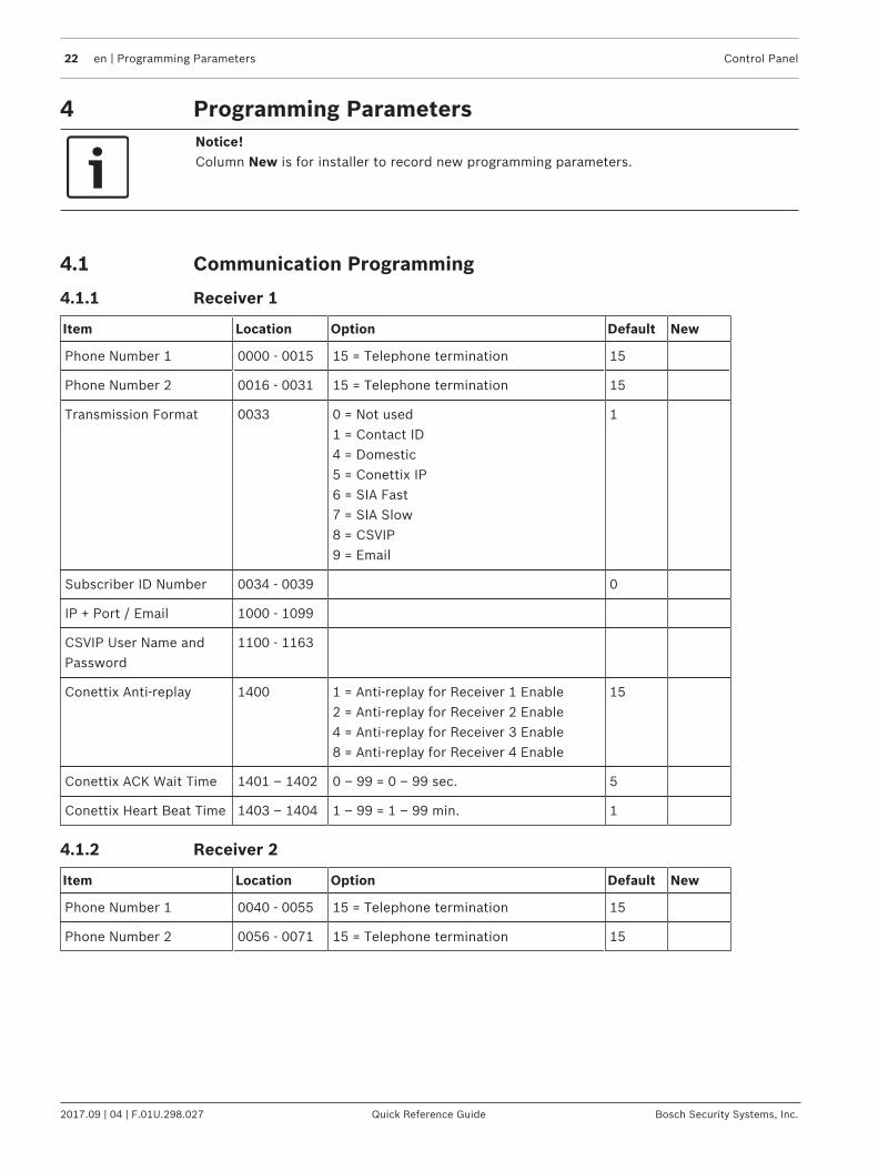
4.1.1 Receiver 1
Item Location Option Default New
Phone Number 1 0000 - 0015 15 = Telephone termination 15
Phone Number 2 0016 - 0031 15 = Telephone termination 15
Transmission Format 0033 0 = Not used1 = Contact ID4 = Domestic5 = Conettix IP6 = SIA Fast7 = SIA Slow8 = CSVIP9 = Email
1
Subscriber ID Number 0034 - 0039 0
IP + Port / Email 1000 - 1099
CSVIP User Name andPassword
1100 - 1163
Conettix Anti-replay 1400 1 = Anti-replay for Receiver 1 Enable2 = Anti-replay for Receiver 2 Enable4 = Anti-replay for Receiver 3 Enable8 = Anti-replay for Receiver 4 Enable
15
Conettix ACK Wait Time 1401 – 1402 0 – 99 = 0 – 99 sec. 5
Conettix Heart Beat Time 1403 – 1404 1 – 99 = 1 – 99 min. 1
4.1.2 Receiver 2
Item Location Option Default New
Phone Number 1 0040 - 0055 15 = Telephone termination 15
Phone Number 2 0056 - 0071 15 = Telephone termination 15

Control Panel Programming Parameters | en 23
Bosch Security Systems, Inc. Quick Reference Guide 2017.09 | 04 | F.01U.298.027
Item Location Option Default New
Transmission Format 0073 0 = Not used1 = Contact ID4 = Domestic5 = Conettix IP6 = SIA Fast7 = SIA Slow8 = CSVIP9 = Email
1
Subscriber ID Number 0074 - 0079 0
IP + Port / Email 1200 - 1299
CSVIP User Name andPassword
1300 - 1363
Conettix Anti-replay 1400 1 = Anti-replay for Receiver 1 Enable2 = Anti-replay for Receiver 2 Enable4 = Anti-replay for Receiver 3 Enable8 = Anti-replay for Receiver 4 Enable
15
Conettix ACK Wait Time 1405 – 1406 0 – 99 = 0 – 99 sec. 5
Conettix Heart Beat Time 1407 – 1408 1 – 99 = 1 – 99 min. 1
4.1.3 Receiver 3
Item Location Option Default New
Phone Number 1 1417 - 1432 15 = Telephone termination 15
Phone Number 2 1433 - 1448 15 = Telephone termination 15
Transmission Format 1450 0 = Not used1 = Contact ID4 = Domestic5 = Conettix IP6 = SIA Fast7 = SIA Slow8 = CSVIP9 = Email
1
Subscriber ID Number 1451 - 1456 0
IP + Port / Email 2060 - 2159
CSVIP User Name andPassword
2160 - 2223
Conettix Anti-replay 1400 1 = Anti-replay for Receiver 1 Enable2 = Anti-replay for Receiver 2 Enable4 = Anti-replay for Receiver 3 Enable8 = Anti-replay for Receiver 4 Enable
15
Conettix ACK Wait Time 1409 – 1410 0 – 99 = 0 – 99 sec. 5
Conettix Heart Beat Time 1411 – 1412 1 – 99 = 1 – 99 min. 1

24 en | Programming Parameters Control Panel
2017.09 | 04 | F.01U.298.027 Quick Reference Guide Bosch Security Systems, Inc.
4.1.4 Receiver 4
Item Location Option Default New
Phone Number 1 1457 - 1472 15 = Telephone termination 15
Phone Number 2 1473 - 1488 15 = Telephone termination 15
Transmission Format 1490 0 = Not used1 = Contact ID4 = Domestic5 = Conettix IP6 = SIA Fast7 = SIA Slow8 = CSVIP9 = Email
1
Subscriber ID Number 1491 - 1496 0
IP + Port / Email 2260 - 2359
CSVIP User Name andPassword
2360 - 2423
Conettix Anti-replay 1400 1 = Anti-replay for Receiver 1 Enable2 = Anti-replay for Receiver 2 Enable4 = Anti-replay for Receiver 3 Enable8 = Anti-replay for Receiver 4 Enable
15
Conettix ACK Wait Time 1413 – 1414 0 – 99 = 0 – 99 sec. 5
Conettix Heart Beat Time 1415 – 1416 1 – 99 = 1 – 99 min. 1
Notice!Recommend to use A-Link Plus Software or Alphanumeric codepad IUI-SOL-TEXT to enter IPitems. Or enter IP items via ASCII Character Codes with ICON codepad IUI-SOL-ICON .
Program IP items with A-Link Plus Software or Alphanumeric codepad1. Select Comm -> Receiver Config -> Transmit Format, select CSVIP for Receiver 1, 2, 3 or
4.2. Select Comm -> Receiver Config -> Subscriber ID Number, enter Subscriber ID Number.3. Select Comm -> Network Config , select module 1 or 2 as Use, do not configure.4. Select Comm -> Receiver Config -> IP + Port / Email, enter IP and the Port, for example,
192.168.226.17:12000.5. Select Comm -> Receiver Config -> CSVIP User Name And Password, enter CSVIP User
Name and Password:– Both user name and password, enter as user name with comma and password with
comma, for example, USER 1, 2580,.– Only user name, enter as user name with two commas, for example, USER 1,,.– Only password, enter as comma, followed by password with comma, for example, ,
2580,.– No user name and password, only enter two commas.
For A-Link Plus, enter up to 32 case sensitive alphanumeric characters for CSVIP User Nameand Password directly through keyboard.For Alphanumeric codepad, enter sensitive alphanumeric characters as below table.

Control Panel Programming Parameters | en 25
Bosch Security Systems, Inc. Quick Reference Guide 2017.09 | 04 | F.01U.298.027
Codepad Key Characters / Function Codepad key Characters / Function
▲ Step back former character 6 [ m ], [ n ], [ o ], [ 6 ]
_ Exit item setting 7 [ p ], [ q ], [ r ], [ s ], [ 7 ]
▼ Move to next character 8 [ t ], [ u ], [ v ], [ 8 ]
1 [ . ], [ @ ], [ : ], [ _ ], [ 1 ] 9 [ w ], [ x ], [ y ], [ z ], [ 9 ]
2 [ a ], [ b ], [ c ], [ 2 ] * Case shift
3 [ d ], [ e ], [ f ], [ 3 ] 0 [ Space ], [ , ], [ / ], [ ? ], [ 0 ]
4 [ g ], [ h ], [ i ], [ 4 ] # Confirm item setting
5 [ j ], [ k ], [ l ], [ 5 ]
Tab. 4.12: Alphanumeric on Alphanumeric codepad
Program Email with A-Link Plus Software
Notice!For the network module B426, Panel Programming Enable shall be defaulted Yes in theMaintenance Page of the web-based configuration menus.
Notice!When A- Link Plus is used to configure the network module, network module parameters willbe replaced by parameters configured in A - Link Plus.Network module parameters, such as IP address and port, must be entered into A-Link Plusas exactly as they are in the module; Web Access Enable must be reset as Enable in A-LinkPlus if access to network module via the web interface is still needed.
1. Select Comm -> Receiver Config -> Transmit Format, select Email.2. Select Comm -> Receiver Config -> Subscriber ID Number, enter Email title with consist
of 6 numbers.3. Selec Comm -> Network Config, select module 1 or 2 as Use and configure or Used,
B4xx-M.4. Select Comm -> Receiver Config -> IP + Port / Email, enter email address of the
recipient.5. Select Network module programming -> Module 1 (or 2) -> Mail Information, enter email
information. Take the sender as test @ 163.com for example, :– Partial mail server name / url : smtp.163.com– Mail server port: 465– Partial ail server user name: test @ 163.com– Mail server password: (enter current password)– Security options: Encrypted
26 en | Programming Parameters Control Panel
2017.09 | 04 | F.01U.298.027 Quick Reference Guide Bosch Security Systems, Inc.
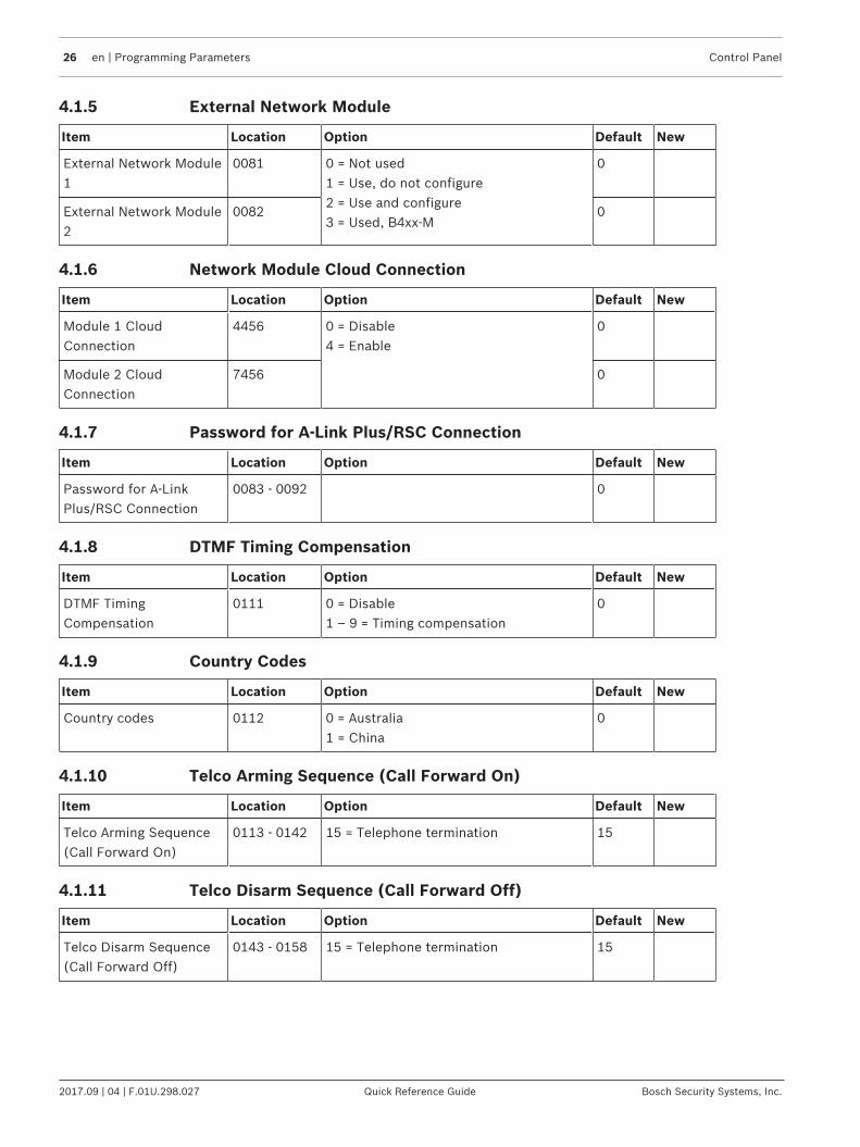
4.1.5 External Network Module
Item Location Option Default New
External Network Module1
0081 0 = Not used1 = Use, do not configure2 = Use and configure3 = Used, B4xx-M
0
External Network Module2
0082 0
4.1.6 Network Module Cloud Connection
Item Location Option Default New
Module 1 CloudConnection
4456 0 = Disable4 = Enable
0
Module 2 CloudConnection
7456 0
4.1.7 Password for A-Link Plus/RSC Connection
Item Location Option Default New
Password for A-LinkPlus/RSC Connection
0083 - 0092 0
4.1.8 DTMF Timing Compensation
Item Location Option Default New
DTMF TimingCompensation
0111 0 = Disable1 – 9 = Timing compensation
0
4.1.9 Country Codes
Item Location Option Default New
Country codes 0112 0 = Australia1 = China
0
4.1.10 Telco Arming Sequence (Call Forward On)
Item Location Option Default New
Telco Arming Sequence(Call Forward On)
0113 - 0142 15 = Telephone termination 15
4.1.11 Telco Disarm Sequence (Call Forward Off)
Item Location Option Default New
Telco Disarm Sequence(Call Forward Off)
0143 - 0158 15 = Telephone termination 15

Control Panel Programming Parameters | en 27
Bosch Security Systems, Inc. Quick Reference Guide 2017.09 | 04 | F.01U.298.027
4.1.12 Call Back Telephone Number
Item Location Option Default New
Call Back TelephoneNumber
0159 - 0174 15 = Telephone termination 15
4.1.13 Ring Count
Item Location Option Default New
Ring Count 0175 0 = Panel does not answer1 - 13 = Number of rings until panelanswers14 = Answering machine bypass 215 = Answering machine bypass 1
8
4.1.14 Telephone Line Fail Options
Item Location Option Default New
Telephone Line FailOptions
0176 1 = Display FAULT Indicator whentelephone line fails2 = Sound alarm when system is armed4 = Sound alarm when system isdisarmed8 = Reserved
0
Notice!Option 2 and 4 must be used in conjunction with Option 1 (for example, program 1,3,5, or 7).
4.1.15 Communication Options 1
Item Location Option Default New
Communication Options1
0177 1 = Reporting functions allowed2 = Remote arming by telephone allowed4 = Answering machine bypass only whenarmed8 = Use Bell 103 for FSK format (Disabled= CCITT V21)
9
4.1.16 Communication Options 2
Item Location Option Default New
Communication Options2
0178 1 = Arm/Disarm Reports only if alarmed2 = STAY Mode Arm/Disarm ReportsEnable4 = Delay siren until transmissioncomplete8 = Extend handshake wait time from 30to 60 sec.
0

28 en | Programming Parameters Control Panel
2017.09 | 04 | F.01U.298.027 Quick Reference Guide Bosch Security Systems, Inc.
4.1.17 Communication Options 3
Item Location Option Default New
Communication Options3
0179 1 = Set DTMF dialing pluses to 1 digit/sec2 = Lockout telephone line fail alarm4 = Reserved8 = Reserved
2
4.1.18 A-Link Plus Options
Item Location Option Default New
A-Link Plus Options 0180 1 = Enable upload/download using A-Link2 = Enable A-Link callback4 = Terminate A-Link connection on alarm8 = Reserved
3
4.2 Installer Code
Item Location Option Default New
Installer Code 0181018201830184
1234
4.3 User Code Programming
Item Location Default New Authority LevelLocation
Default New
User #01 0185018601870188
2580
0189 10
User #02 0190 - 0193 15 0194 2
User #03 0195 - 0198 15 0199 2
User #04 0200 - 0203 15 0204 2
User #05 0205 - 0208 15 0209 2
User #06 0210 - 0213 15 0214 2
User #07 0215 - 0218 15 0219 2
User #08 02200221 - 0223
015
0224 3
User #09 0225 - 0228 15 0229 2
User #10 0230 - 0233 15 0234 2
User #11 0235 - 0238 15 0239 2
User #12 0240 - 0243 15 0244 2
User #13 0245 - 0248 15 0249 2

Control Panel Programming Parameters | en 29
Bosch Security Systems, Inc. Quick Reference Guide 2017.09 | 04 | F.01U.298.027
Item Location Default New Authority LevelLocation
Default New
User #14 0250 - 0253 15 0254 2
User #15 0255 - 0258 15 0259 2
User #16 0260 - 0263 15 0264 2
User #17 0566 - 0569 15 0570 2
User #18 0571 - 0574 15 0575 2
User #19 0576 - 0579 15 0580 2
User #20 0581 - 0584 15 0585 2
User #21 0586 - 0589 15 0590 2
User #22 0591 - 0594 15 0595 2
User #23 0596 - 0599 15 0600 2
User #24 0601 -0604 15 0605 2
User #25 0606 - 0609 15 0610 2
User #26 0611 - 0614 15 0615 2
User #27 0616 - 0619 15 0620 2
User #28 0621 - 0624 15 0625 2
User #29 0626 - 0629 15 0630 2
User #30 0631 - 0634 15 0635 2
User #31 0636 - 0639 15 0640 2
User #32 0641 - 0644 15 0645 2
Authority Levels Description
0 Arm/Disarm
1 Arm Only
2 Arm/Disarm and Arm/Disarm Reports
3 Arm Only and Arm Reports
4 Arm/Disarm and Code Required to Isolate
6 Arm/Disarm and Arm/Disarm Reports and Code Required to Isolate
8 Master Code and Arm/Disarm
10 Master Code and Arm/Disarm and Arm/Disarm Reports
12 Master Code and Arm/Disarm and Code Required to Isolate
14 Master Code and Arm/Disarm and Code Required to Isolate and Arm/DisarmReports
Table 4.13: Authority Levels

30 en | Programming Parameters Control Panel
2017.09 | 04 | F.01U.298.027 Quick Reference Guide Bosch Security Systems, Inc.
4.4 Day Alarm Zones
Item Location Option Default New
Day Alarm Zones 0265 1 = Zone 12 = Zone 24 = Zone 38 = Zone 4
0
4.5 EOL Resistor Value
Item Location Option Default New
EOL ResistorValue
0266 0 = No EOL1 = 1k2 = 1k53 = 2k24 = 3k35 = 3k96 = 4k77 = 5k6
8 = 6k89 = 10k10 = 12k11 = 22k12 = Normal open13 = Reserved14 = Split EOL (3k3/6k8with tamper 1k)15 = Split EOL (3k3/6k8)
15
4.6 Zone Programming
Item Location Default New Item Location Default New
Zone #01 Zone #02
Zone Type 0267 2 Zone Type 0274 1
Zone Pulse Count 0268 0 Zone Pulse Count 0275 0
Zone Pulse Count Time 0269 0 Zone Pulse Count Time 0276 0
Zone Options 1 0270 1 Zone Options 1 0277 1
Zone Options 2 0271 14 Zone Options 2 0278 14
Reserved 0272 Reserved 0279
Zone Report Options 0273 1 Zone Report Options 0280 1
Zone #03 Zone #04
Zone Type 0281 1 Zone Type 0288 1
Zone Pulse Count 0282 0 Zone Pulse Count 0289 0
Zone Pulse Count Time 0283 0 Zone Pulse Count Time 0290 0
Zone Options 1 0284 1 Zone Options 1 0291 1
Zone Options 2 0285 14 Zone Options 2 0292 14
Reserved 0286 Reserved 0293
Zone Report Options 0287 1 Zone Report Options 0294 1
Zone #05 Zone #06
Zone Type 0295 0 Zone Type 0302 0

Control Panel Programming Parameters | en 31
Bosch Security Systems, Inc. Quick Reference Guide 2017.09 | 04 | F.01U.298.027
Item Location Default New Item Location Default New
Zone Pulse Count 0296 0 Zone Pulse Count 0303 0
Zone Pulse Count Time 0297 0 Zone Pulse Count Time 0304 0
Zone Options 1 0298 1 Zone Options 1 0305 1
Zone Options 2 0299 14 Zone Options 2 0306 14
Reserved 0300 Reserved 0307
Zone Report Options 0301 1 Zone Report Options 0308 1
Zone #07 Zone #08
Zone Type 0309 0 Zone Type 0316 9
Zone Pulse Count 0310 0 Zone Pulse Count 0317 0
Zone Pulse Count Time 0311 0 Zone Pulse Count Time 0318 0
Zone Options 1 0312 1 Zone Options 1 0319 1
Zone Options 2 0313 14 Zone Options 2 0320 12
Reserved 0314 Reserved 0321
Zone Report Options 0315 1 Zone Report Options 0322 1
Zone #09 Zone #10
Zone Type 0323 15 Zone Type 0330 15
Zone Pulse Count 0324 0 Zone Pulse Count 0331 0
Zone Pulse Count Time 0325 0 Zone Pulse Count Time 0332 0
Zone Options 1 0326 1 Zone Options 1 0333 1
Zone Options 2 0327 14 Zone Options 2 0334 14
Reserved 0328 Reserved 0335
Zone Report Options 0329 1 Zone Report Options 0336 1
Zone #11 Zone #12
Zone Type 0337 15 Zone Type 0344 15
Zone Pulse Count 0338 0 Zone Pulse Count 0345 0
Zone Pulse Count Time 0339 0 Zone Pulse Count Time 0346 0
Zone Options 1 0340 1 Zone Options 1 0347 1
Zone Options 2 0341 14 Zone Options 2 0348 14
Reserved 0342 Reserved 0349
Zone Report Options 0343 1 Zone Report Options 0350 1
Zone #13 Zone #14
Zone Type 0351 15 Zone Type 0358 15
Zone Pulse Count 0352 0 Zone Pulse Count 0359 0

32 en | Programming Parameters Control Panel
2017.09 | 04 | F.01U.298.027 Quick Reference Guide Bosch Security Systems, Inc.
Item Location Default New Item Location Default New
Zone Pulse Count Time 0353 0 Zone Pulse Count Time 0360 0
Zone Options 1 0354 1 Zone Options 1 0361 1
Zone Options 2 0355 14 Zone Options 2 0362 14
Reserved 0356 Reserved 0363
Zone Report Options 0357 1 Zone Report Options 0364 1
Zone #15 Zone #16
Zone Type 0365 15 Zone Type 0372 15
Zone Pulse Count 0366 0 Zone Pulse Count 0373 0
Zone Pulse Count Time 0367 0 Zone Pulse Count Time 0374 0
Zone Options 1 0368 1 Zone Options 1 0375 1
Zone Options 2 0369 14 Zone Options 2 0376 14
Reserved 0370 Reserved 0377
Zone Report Options 0371 1 Zone Report Options 0378 1
Item Location Default New Item Location Default New
Zone 1 Source 0754 0 Zone 2 Source 0755 0
Zone 3 Source 0756 0 Zone 4 Source 0757 0
Zone 5 Source 0758 0 Zone 6 Source 0759 0
Zone 7 Source 0760 0 Zone 8 Source 0761 0
Zone 9 Source 0762 0 Zone 10 Source 0763 0
Zone 11 Source 0764 0 Zone 12 Source 0765 0
Zone 13 Source 0766 0 Zone 14 Source 0767 0
Zone 15 Source 0768 0 Zone 16 Source 0769 0
For zone item options, refer to below Zone Item Options.
Item Option
Zone Type 0 = Instant1 = Handover2 = Delay-13 = Delay-24 = Reserved5 = Reserved6 = 24-Hour Medical7 = 24-Hour Panic
8 = 24-Hour Hold-up9 = 24-Hour Tamper10 = Reserved11 = Keyswitch12 = 24-Hour Burglary13 = 24-Hour Fire14 = Chime Only15 = Not used
Zone Pulse Count Use the pulse count to program how many pulses (0 to 15) need tobe registered within the pulse count time to activate an alarm.
Zone Pulse Count Time 20 ms Loop Response Time 150 ms Loop Response Time

Control Panel Programming Parameters | en 33
Bosch Security Systems, Inc. Quick Reference Guide 2017.09 | 04 | F.01U.298.027
Item Option
0 = 0.5 sec.1 = 1 sec.2 = 2 sec.3 = 3 sec.4 = 4 sec.5 = 5 sec.6 = 10 sec.7 = 15 sec.
8 = 20 sec.9 = 30 sec.10 = 40 sec.11 = 50 sec.12 = 60 sec.13 = 90 sec.14 = 120 sec.15 = 200 sec.
Zone Options 1 1 = Lockout siren/report2 = Delay alarm report4 = Silent alarm8 = Sensor watch
Zone Options 2 1 = Isolated in STAY Mode 12 = Zone isolation allowed4 = Forced arming allowed8 = Zone Restore Report allowed
Zone Report Options 0 = No zone reports allowed1 = Report to Receiver 12 = Report to Receiver 23 = Report to Receiver 34 = Report to Receiver 45 = Report to Receiver 1,2,3,46 = Report to Receiver 1 (2,3,4 backup)7 = Report to Receiver 1 (2 backup) and Receiver 3 (4 backup)
Keyswitch Zone Options 0 = Latching arm and disarm in AWAY Mode1 = Latching arm in AWAY Mode2 = Latching disarm from AWAY Mode or STAY Mode4 = Latching arm and disarm in STAY Mode 15 = Latching arm in STAY Mode 16 = Latching disarm from STAY Mode8 = Momentary arm and disarm in AWAY Mode9 = Momentary arm in AWAY Mode10 = Momentary disarm from AWAY Mode or STAY Mode12 = Momentary arm and disarm in STAY Mode 113 = Momentary arm in STAY Mode 114 = Momentary disarm from STAY Mode
Zone Source 0 = Onboard1 = RF2 = B228
Table 4.14: Zone Item Options
The keyswitch zone options replace Zone Options 1 only for the zones that were programmedto operate as a keyswitch zone.
34 en | Programming Parameters Control Panel
2017.09 | 04 | F.01U.298.027 Quick Reference Guide Bosch Security Systems, Inc.
Notice!Solution 2000 supports onboard inputs only.
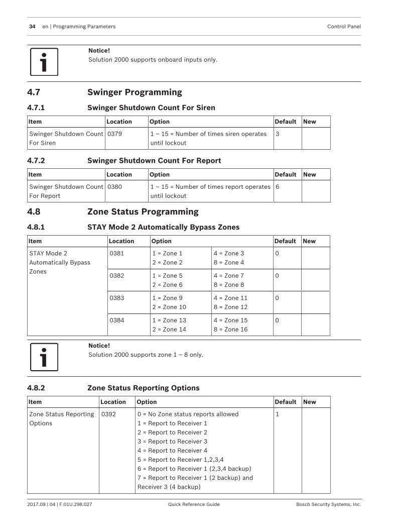
4.7 Swinger Programming
4.7.1 Swinger Shutdown Count For Siren
Item Location Option Default New
Swinger Shutdown CountFor Siren
0379 1 – 15 = Number of times siren operatesuntil lockout
3
4.7.2 Swinger Shutdown Count For Report
Item Location Option Default New
Swinger Shutdown CountFor Report
0380 1 – 15 = Number of times report operatesuntil lockout
6
4.8 Zone Status Programming
4.8.1 STAY Mode 2 Automatically Bypass Zones
Item Location Option Default New
STAY Mode 2Automatically BypassZones
0381 1 = Zone 12 = Zone 2
4 = Zone 38 = Zone 4
0
0382 1 = Zone 52 = Zone 6
4 = Zone 78 = Zone 8
0
0383 1 = Zone 92 = Zone 10
4 = Zone 118 = Zone 12
0
0384 1 = Zone 132 = Zone 14
4 = Zone 158 = Zone 16
0
Notice!Solution 2000 supports zone 1 – 8 only.
4.8.2 Zone Status Reporting Options
Item Location Option Default New
Zone Status ReportingOptions
0392 0 = No Zone status reports allowed1 = Report to Receiver 12 = Report to Receiver 23 = Report to Receiver 34 = Report to Receiver 45 = Report to Receiver 1,2,3,46 = Report to Receiver 1 (2,3,4 backup)7 = Report to Receiver 1 (2 backup) andReceiver 3 (4 backup)
1

Control Panel Programming Parameters | en 35
Bosch Security Systems, Inc. Quick Reference Guide 2017.09 | 04 | F.01U.298.027
4.9 RF Programming
4.9.1 RF Supervision Time
Item Location Option Default New
RF Supervision Time(Only for Solution3000 )
0393 0 = Disable2 = 2 hours3 = 4 hours4 = 12 hours
5 = 24 hours6 = 48 hours7 = 72 hours
0
4.9.2 RADION Anti-Jamming Sensitivity
Item Location Option Default New
RADION Anti-Jamming Sensitivity(Only for Solution 3000 )
0394 0 = Most Sensitive15 = Least Sensitive
12
4.9.3 RF Receiver
Item Location Option Default New
RF Receiver 0395 0 = Not used1 = Use RADION receiver B8102 = Use WE800EV2
0
4.9.4 RF Options
Item Location Option Default New
RF Options(Only for Solution 3000 )
0396 1 = Siren Sound On RFReceiver Fail2 = RF Receiver Jam/TamperSiren Alarm4 = Unseal Zone That FailMonitor
0
4.10 Report Programming
4.10.1 Arm / Disarm Reporting Options
Item Location Option Default New
Arm / DisarmReporting Options
0403 0 = No Arm / Disarm Reports allowed1 = Report to Receiver 12 = Report to Receiver 23 = Report to Receiver 34 = Report to Receiver 45 = Report to Receiver 1,2,3,46 = Report to Receiver 1 (2,3,4 backup)7 = Report to Receiver 1 (2 backup) andReceiver 3 (4 backup)
1

36 en | Programming Parameters Control Panel
2017.09 | 04 | F.01U.298.027 Quick Reference Guide Bosch Security Systems, Inc.
4.10.2 Codepad Reporting Options
Item Location Option Default New
Codepad ReportingOptions
0411 0 = No Codepad Alarm Reports allowed1 = Report to Receiver 12 = Report to Receiver 23 = Report to Receiver 34 = Report to Receiver 45 = Report to Receiver 1,2,3,46 = Report to Receiver 1 (2,3,4 backup)7 = Report to Receiver 1 (2 backup) andReceiver 3 (4 backup)
1
4.11 System Status Programming
4.11.1 Access Denied(Code Retry)
Item Location Option Default New
Code retry limit 0424 0 = Unlimited1 – 15 = Error code attempts
6
4.11.2 System Status Reporting Options
Item Location Option Default New
System StatusReporting Options
0427 0 = No report required1 = Report to Receiver 12 = Report to Receiver 23 = Report to Receiver 34 = Report to Receiver 45 = Report to Receiver 1,2,3,46 = Report to Receiver 1 (2,3,4 backup)7 = Report to Receiver 1 (2 backup) andReceiver 3 (4 backup)
1
4.12 Test Report Programming
4.12.1 Test Report Time (Automatic)
Item Location Option Default New
Hour of day (tens digit) 0428 0
Hour of day (units digit) 0429 0
Minute of day (tens digit) 0430 0
Minute of day (units digit) 0431 0
Repeat interval in days 0434 0 = Disable1 – 15 = 1 – 15 days
0

Control Panel Programming Parameters | en 37
Bosch Security Systems, Inc. Quick Reference Guide 2017.09 | 04 | F.01U.298.027
4.12.2 Test Reporting Options
Item Location Option Default New
Test Reporting Options 0435 0 = No report required1 = Report to Receiver 12 = Report to Receiver 23 = Report to Receiver 34 = Report to Receiver 45 = Report to Receiver 1,2,3,46 = Report to Receiver 1 (2,3,4 backup)7 = Report to Receiver 1 (2 backup) andReceiver 3 (4 backup)
1

38 en | Programming Parameters Control Panel
2017.09 | 04 | F.01U.298.027 Quick Reference Guide Bosch Security Systems, Inc.
4.13 Output Programming
Item Location Default New Item Location Default New
Output 1 (Default = Horn Speaker) Output 2 (Default = Fire Alarm With Verification)
Event Code 0436 1 Event Code 0442 2
Event Code 0437 14 Event Code 0443 7
Polarity 0438 0 Polarity 0444 10
Time Base 0439 0 Time Base 0445 2
Time Base Multiplier 0440 0 Time Base Multiplier 0446 1
Time Base Multiplier 0441 0 Time Base Multiplier 0447 5
Output 3 (Default = Strobe – Reset After 8 hrs.) Relay Output (Default = Sirens Running)
Event Code 0448 2 Event Code 0454 1
Event Code 0449 0 Event Code 0455 15
Polarity 0450 6 Polarity 0456 1
Time Base 0451 4 Time Base 0457 0
Time Base Multiplier 0542 0 Time Base Multiplier 0458 0
Time Base Multiplier 0453 8 Time Base Multiplier 0459 0
Codepad Buzzer (Default = Entry/Exit Warning andDay Alarm)
Event Code 0460 0
Event Code 0461 13
Polarity 0462 2
Time Base 0463 1
Time Base Multiplier 0464 0
Time Base Multiplier 0465 9

Control Panel Programming Parameters | en 39
Bosch Security Systems, Inc. Quick Reference Guide 2017.09 | 04 | F.01U.298.027
Item Location Default New Item Location Default New
B308 Output 1 B308 Output 2
Event Code 0646 0 Event Code 0652 0
Event Code 0647 0 Event Code 0653 0
Polarity 0648 0 Polarity 0654 0
Time Base 0649 0 Time Base 0655 0
Time Base Multiplier 0650 0 Time Base Multiplier 0656 0
Time Base Multiplier 0651 0 Time Base Multiplier 0657 0
B308 Output 3 B308 Output 4
Event Code 0658 0 Event Code 0664 0
Event Code 0659 0 Event Code 0665 0
Polarity 0660 0 Polarity 0666 0
Time Base 0661 0 Time Base 0667 0
Time Base Multiplier 0662 0 Time Base Multiplier 0668 0
Time Base Multiplier 0663 0 Time Base Multiplier 0669 0
B308 Output 5 B308 Output 6
Event Code 0670 0 Event Code 0676 0
Event Code 0671 0 Event Code 0677 0
Polarity 0672 0 Polarity 0678 0
Time Base 0673 0 Time Base 0679 0
Time Base Multiplier 0674 0 Time Base Multiplier 0680 0
Time Base Multiplier 0675 0 Time Base Multiplier 0681 0
B308 Output 7 B308 Output 8
Event Code 0682 0 Event Code 0688 0
Event Code 0683 0 Event Code 0689 0
Polarity 0684 0 Polarity 0690 0
Time Base 0685 0 Time Base 0691 0
Time Base Multiplier 0686 0 Time Base Multiplier 0692 0
Time Base Multiplier 0687 0 Time Base Multiplier 0693 0

40 en | Programming Parameters Control Panel
2017.09 | 04 | F.01U.298.027 Quick Reference Guide Bosch Security Systems, Inc.
Item Location Default New Item Location Default New
B308 Output 9 B308 Output 10
Event Code 0694 0 Event Code 0700 0
Event Code 0695 0 Event Code 0701 0
Polarity 0696 0 Polarity 0702 0
Time Base 0697 0 Time Base 0703 0
Time Base Multiplier 0698 0 Time Base Multiplier 0704 0
Time Base Multiplier 0699 0 Time Base Multiplier 0705 0
B308 Output 11 B308 Output 12
Event Code 0706 0 Event Code 0712 0
Event Code 0707 0 Event Code 0713 0
Polarity 0708 0 Polarity 0714 0
Time Base 0709 0 Time Base 0715 0
Time Base Multiplier 0710 0 Time Base Multiplier 0716 0
Time Base Multiplier 0711 0 Time Base Multiplier 0717 0
B308 Output 13 B308 Output 14
Event Code 0718 0 Event Code 0724 0
Event Code 0719 0 Event Code 0725 0
Polarity 0720 0 Polarity 0726 0
Time Base 0721 0 Time Base 0727 0
Time Base Multiplier 0722 0 Time Base Multiplier 0728 0
Time Base Multiplier 0723 0 Time Base Multiplier 0729 0
B308 Output 15 B308 Output 16
Event Code 0730 0 Event Code 0736 0
Event Code 0731 0 Event Code 0737 0
Polarity 0732 0 Polarity 0738 0
Time Base 0733 0 Time Base 0739 0
Time Base Multiplier 0734 0 Time Base Multiplier 0740 0
Time Base Multiplier 0735 0 Time Base Multiplier 0741 0
Item Location Default New Item Location Default New
B228 Output 1 B228 Output 2
Output Mode 0770 0 Output Mode 0771 0
Event Code 0742 0 Event Code 0748 0
Event Code 0743 0 Event Code 0749 0

Control Panel Programming Parameters | en 41
Bosch Security Systems, Inc. Quick Reference Guide 2017.09 | 04 | F.01U.298.027
Item Location Default New Item Location Default New
Polarity 0744 0 Polarity 0750 0
Time Base 0745 0 Time Base 0751 0
Time Base Multiplier 0746 0 Time Base Multiplier 0752 0
Time Base Multiplier 0747 0 Time Base Multiplier 0753 0
For output item options, refer to below Output Item Options.
Item Option
B228 Output Mode 0 = Not used1 = Aux power
2 = Switched negative4 = Open collector
Event Code 0 0 = Reserved0 1 = System armed0 2 = System disarmed0 3 = Armed in STAY mode0 4 = Armed in AWAY mode0 5 = Pre-arming alert0 6 = Exit Warning (all zones sealed) andentry warning0 7 = Exit Warning0 8 = Exit Warning finished0 9 = Kiss-off after end of Exit Time0 10 = Reserved0 11 = Entry warning0 12 = Entry warning and day alarm resetting0 13 = Exit warning and entry warning andday alarm resetting0 14 = Day alarm resetting0 15 = Day alarm latching
1 0 = Day alarm enabled1 1 = Telephone line fail1 2 = Kiss-off received1 3 = AUX Power Supply fail1 4 = AC fail1 5 = Low battery1 6 = Output 1 fail1 7 = Sensor watch alarm1 8 = Codepad medical alarm1 9 = Codepad fire alarm1 10 = Codepad panic alarm1 11 = Codepad duress alarm1 12 = Access denied (code retries)1 13 = Reserved1 14 = Horn speaker (output 1 only)1 15 = Siren running
Event Code 2 0 = Strobe2 1 = Silent alarm2 2 = Alarm in STAY mode2 3 = Alarm in AWAY mode2 4 = System fault2 5 = Fire alarm (resetting)2 6 = Fire alarm (latching)2 7 = Fire alarm (verification)2 8 = Remote control 12 9 = Remote control 22 10 = Remote control 32 11 = Radio control output 12 12 = Radio control output 22 13 = Radio control output 1- not in AWAYMode2 14 = Radio control output 2- not in AWAYMode2 15 = Communications fail after 3 attempts
3 0 = Communications fail3 1 = Report disabled3 2 = Report active (on-line)3 3 = Ring detect3 4 = Codepad/Keyfob panic3 5 = Mimic zone 13 6 = Mimic zone 23 7 = Mimic zone 33 8 = Mimic zone 43 9 = Mimic zone 53 10 = Mimic zone 63 11 = Mimic zone 73 12 = Mimic zone 83 13 = Mimic zone 93 14 = Mimic zone 103 15 = Mimic zone 11

42 en | Programming Parameters Control Panel
2017.09 | 04 | F.01U.298.027 Quick Reference Guide Bosch Security Systems, Inc.
Item Option
Event Code 4 0 = Mimic zone 124 1 = Mimic zone 134 2 = Mimic zone 144 3 = Mimic zone 154 4 = Mimic zone 164 5 = Chime4 6 = Zone not sealed4 7 = Zone not sealed after Exit Time4 8 = Reserved4 9 = AC MAINS cycle (60 Hz or 50 Hz)4 10 = Area 1 – zone unsealed4 11 = Area 2 – zone unsealed4 12 = Reserved4 13 = Reserved4 14 = Reserved4 15 = Reserved
5 0 = Reserved5 1 = Reserved5 2 = Area 1 in alarm5 3 = Area 2 in alarm5 4 = Reserved5 5 = Reserved5 6 = Area 1 armed5 7 = Area 2 armed5 8 = Reserved5 9 = Reserved5 10 = Area 1 disarmed5 11 = Area 2 disarmed5 12 = Reserved5 13 = Reserved5 14 = Any areas armed5 15 = Any areas disarmed
Event Code 6 0 = Reserved6 1 = Reserved6 2 = Remote control 46 3 = Remote control 56 4 = Remote control 66 5 = Remote control 76 6 = Remote control 86 7 = Remote control 96 8 = Remote control 106 9 = Remote control 116 10 = Remote control 12
6 11 = Remote control 136 12 = Remote control 146 13 = Remote control 156 14 = Remote control 166 15 = Remote control 177 0 = Remote control 187 1 = Remote control 197 2 = Remote control 207 3 = Remote control 217 4 = Remote control 22
Polarity (Modes) 0 = Output not used1 = Normally open, going low2 = Normally open, pulsing low3 = Normally open, one shot low4 = Normally open, one shot low (reactivate)5 = Normally open, one shot low (can reset)6 = Normally open, one shot low (alarm)7 = Normally open, latching low
8 = Normally low, going open9 = Normally low, pulsing open10 = Normally low, one shot open11 = Normally low, one shot open(reactivate)12 = Normally low, one shot open (canreset)13 = Normally low, one shot open (alarm)14 = Normally low, latching open
Time Base 0 = Reserved1 = 200 ms2 = 1 sec.
3 = 1 min.4 = 1 hr.
Time Base Multiplier Enter a value between 00 and 99.
Table 4.15: Output Item Options
* One Shot ModeWhen you program the output polarity as one shot, the time base is multiplied by the timebase multiplier. (For example, if the time base = 2 and the multiplier = 05, the output operatesfor 5 sec.)

Control Panel Programming Parameters | en 43
Bosch Security Systems, Inc. Quick Reference Guide 2017.09 | 04 | F.01U.298.027
*Pulsing ModeWhen you program the output polarity as pulsing, the time base becomes the ON time and themultiplier becomes the OFF time. The OFF time is the time base x the multiplier. (Forexample, if you want the output to pulse 1 sec. ON and 5 sec. OFF, you would program timebase as 2 and the multiplier as 05.)
Notice!When event code Remote control 1 – 20 is selected, polarity mode shall be programmed astime-independent option (including 1 = Normally open, going low, or 7, or 8, and 14).
4.14 Time Programming
4.14.1 Entry Time 1
Item Location Option Default New
Increments of 1 sec. (0 to 15 sec.) 0466 4
Increments of 16 sec. (0 to 240 sec.) 0467 1
4.14.2 Entry Time 2
Item Location Option Default New
Increments of 1 sec. (0 to 15 sec.) 0468 8
Increments of 16 sec. (0 to 240 sec.) 0469 2
4.14.3 Exit Time (AWAY/STAY Modes)
Item Location Option Default New
Increments of 1 sec. (0 to 15 sec.) 0470 12
Increments of 16 sec. (0 to 240 sec.) 0471 3
4.14.4 Entry Guard Time For STAY Mode
Item Location Option Default New
Increments of 1 sec. (0 to 15 sec.) 0472 0
Increments of 1 6sec. (0 to 240 sec.) 0473 0
4.14.5 Delay Alarm Report Time
Item Location Option Default New
Increments of 1 sec. (0 to 15 sec.) 0474 0
Increments of 16 sec. (0 to 240 sec.) 0475 0
4.14.6 Sensor Watch Time
Item Location Option Default New
Increments of days (tens digit) 0476 0
Increments of days (units digit) 0477 0

44 en | Programming Parameters Control Panel
2017.09 | 04 | F.01U.298.027 Quick Reference Guide Bosch Security Systems, Inc.
4.14.7 Codepad Lockout Time
Item Location Option Default New
Codepad Lockout Time 0478 0 = No lockout1 – 15 = Lockout time 10 – 150 sec.(Increments of 10 sec.)
0
4.14.8 Siren Run Time
Item Location Option Default New
Siren Run Time 0479 0 = No Siren time1 – 15 = Siren time 1 – 15 min. (increments of1 min.)
5
4.14.9 Siren Sound Rate
Item Location Option Default New
Siren Sound Rate 0480 0 = Slowest frequency15 = Fastest frequency
7
4.14.10 Auto Arming Pre-Alert Time
Item Location Option Default New
Auto Arming Pre-Alert Time 0481 0 = No alert time1 – 15 = Alert time 5 – 75 min.(increments of 5 min.)
1
4.14.11 Auto Arming Time
Item Location Option Default New
Hour of the day (tens digit) 0482 0
Hour of the day (units digit) 0483 0
Minute of the day (tens digit) 0484 0
Minute of the day (units digit) 0485 0
4.14.12 Auto Disarming Time
Item Location Option Default New
Hour of the day (tens digit) 0486 0
Hour of the day (units digit) 0487 0
Minute of the day (tens digit) 0488 0
Minute of the day (units digit) 0489 0
4.14.13 Kiss-Off Wait Time
Item Location Option Default New
Increments of 500 ms (500 ms to 8sec.)
0490 3

Control Panel Programming Parameters | en 45
Bosch Security Systems, Inc. Quick Reference Guide 2017.09 | 04 | F.01U.298.027
4.14.14 Speaker Beep Volume
Item Location Option Default New
Speaker Beep Volume 0491 0 = No Beeps15 = Loudest Beeps
13
4.15 Options Programming
4.15.1 System Options 1
Item Location Option Default New
System Options 1 0492 1 = Bosch Security Systems smart lockoutallowed2 = Warning device fault monitor4 = Strobe indication for radio arm/disarm8 = Assign button 4 on keyfob to operate STAYMode 1
1
Notice!Option 2 is available only when the warning device (such as horn speaker) is connected toany of the output 1 – 3.
4.15.2 System Options 2
Item Location Option Default New
System Options 2 0493 1 = Codepad panic to be silent2 = Codepad fire to be silent4 = Codepad medical to be silent8 = Access denied (code retries) to be silent
0
4.15.3 System Options 3
Item Location Option Default New
System Options 3 0494 1 = AC fail after 1 hr. (Disabled = after 2 min.)2 = Ignore AC fail4 = Pulse count handover allowed8 = Handover delay to be sequential
8
4.15.4 System Options 4
Item Location Option Default New
System Options 4 0495 1 = Panel to power up disarmed (if powerreset)2 = Arm/disarm tracking on power up4 = Onboard tamper trigger alarm8 = Reserved
6

46 en | Programming Parameters Control Panel
2017.09 | 04 | F.01U.298.027 Quick Reference Guide Bosch Security Systems, Inc.
4.15.5 System Options 5
Item Location Option Default New
System Options 5 0110 1 = Domestic Dial Fail to Report2 = Installer Arm/Disarm Function4 = Reserved8 = Reserved
0
4.15.6 Consumer Options 1
Item Location Option Default New
Consumer Options 1 0496 1 = Test reports only when armed2 = Test report after siren reset4 = Auto arm in STAY Mode 18 = STAY indicator to display day alarm status
0
4.15.7 Consumer Options 2
Item Location Option Default New
Consumer Options 2 0497 1 = Codepad displays extinguish after 60 sec.2 = Single button arming allowed (AWAY/STAYModes 1 and 2)4 = Single button disarming allowed (STAYModes 1 and 2)8 = Alarm memory reset on disarm
2
4.15.8 Consumer Options 3
Item Location Option Default New
Consumer Options 3 0498 1 = Codepad fault beeps allowed2 = Use digit 3 for codepad duress alarm(instead of digit 9)4 = Alarms activate sirens and strobe outputsin STAY Modes 1 and 28 = Zone tamper alarms to be silent
5
4.15.9 Partitioning Options 1
Item Location Option Default New
Partitioning Options 1 0500 1 = First to Disarm/Last to Arm reporting2 = Reserved4 = Reset sirens from any area allowed8 = Reserved
0

Control Panel Programming Parameters | en 47
Bosch Security Systems, Inc. Quick Reference Guide 2017.09 | 04 | F.01U.298.027
4.15.10 Partitioning Options 2
Item Location Option Default New
Partitioning Options 2 0501 1 = Reserved2 = User codes allowed to arm/disarm bothareas at same time (Code [0][#])4 = Reserved8 = Reserved
0
4.16 Partition Allocations
4.16.1 Zone Area Assignment
Item Location Default New Item Location Default New
Zone 1 Area 0502 1 Zone 2 Area 0503 1
Zone 3 Area 0504 1 Zone 4 Area 0505 1
Zone 5 Area 0506 1 Zone 6 Area 0507 1
Zone 7 Area 0508 1 Zone 8 Area 0509 1
Zone 9 Area 0510 1 Zone 10 Area 0511 1
Zone 11 Area 0512 1 Zone 12 Area 0513 1
Zone 13 Area 0514 1 Zone 14 Area 0515 1
Zone 15 Area 0516 1 Zone 16 Area 0517 1
Option
0 = Zone area not assigned1 = Zone assigned to Area 1
2 = Zone assigned to Area 23 = Zone assigned to both Area 1 and Area 2
Notice!Solution 2000 supports zone 1 - 8 only.
4.16.2 Codepad Assignment
Item Location Default New Item Location Default New
Codepad 1 Area 0518 1 Codepad 2 Area 0519 0
Codepad 3 Area 0520 0 Codepad 4 Area 0521 0
Option
0 = Codepad area not assigned1 = Codepad assigned to Area 1
2 = Codepad assigned to Area 23 = Codepad assigned to both Area 1 and Area 2

48 en | Programming Parameters Control Panel
2017.09 | 04 | F.01U.298.027 Quick Reference Guide Bosch Security Systems, Inc.
4.16.3 User Code Area Assignment
Item Location Default New Item Location Default New
User Code 1 0534 1 User Code 2 0535 1
User Code 3 0536 1 User Code 4 0537 1
User Code 5 0538 1 User Code 6 0539 1
User Code 7 0540 1 User Code 8 0541 1
User Code 9 0542 1 User Code 10 0543 1
User Code 11 0544 1 User Code 12 0545 1
User Code 13 0546 1 User Code 14 0547 1
User Code 15 0548 1 User Code 16 0549 1
User Code 17 0550 1 User Code 18 0551 1
User Code 19 0552 1 User Code 20 0553 1
User Code 21 0554 1 User Code 22 0555 1
User Code 23 0556 1 User Code 24 0557 1
User Code 25 0558 1 User Code 26 0559 1
User Code 27 0560 1 User Code 28 0561 1
User Code 29 0562 1 User Code 30 0563 1
User Code 31 0564 1 User Code 32 0565 1
Option
0 = User code not assigned1 = User code assigned to Area 1
2 = User code assigned to Area 23 = User code assigned to both Area 1 and Area 2
4.17 Default Options
Item Location Option Default New
Button Default Options 0900 0 = Button Factory Default Enable15 = Button Factory Default Disabled
0

Control Panel Programming Parameters | en 49
Bosch Security Systems, Inc. Quick Reference Guide 2017.09 | 04 | F.01U.298.027
4.18 RFID Programming
4.18.1 Keyfob RFID
Item Location Default New Item Location Default New
Keyfob #01 1500 - 1507 0 Keyfob #02 1510 - 1517 0
Keyfob #03 1520 - 1527 0 Keyfob #04 1530 - 1537 0
Keyfob #05 1540 - 1547 0 Keyfob #06 1550 - 1557 0
Keyfob #07 1560 - 1567 0 Keyfob #08 1570 - 1577 0
Keyfob #09 1580 - 1587 0 Keyfob #10 1590 - 1597 0
Keyfob #11 1600 - 1607 0 Keyfob #12 1610 - 1617 0
Keyfob #13 1620 - 1627 0 Keyfob #14 1630 - 1637 0
Keyfob #15 1640 - 1647 0 Keyfob #16 1650 - 1657 0
Keyfob #17 1660 - 1667 0 Keyfob #18 1670 - 1677 0
Keyfob #19 1680 - 1687 0 Keyfob #20 1690 - 1697 0
Keyfob #21 1700 - 1707 0 Keyfob #22 1710 - 1717 0
Keyfob #23 1720 - 1727 0 Keyfob #24 1730 - 1737 0
Keyfob #25 1740 - 1747 0 Keyfob #26 1750 - 1757 0
Keyfob #27 1760 - 1767 0 Keyfob #28 1770 - 1777 0
Keyfob #29 1780 - 1787 0 Keyfob #30 1790 - 1797 0
Keyfob #31 1800 - 1807 0 Keyfob #32 1810 - 1817 0

50 en | Programming Parameters Control Panel
2017.09 | 04 | F.01U.298.027 Quick Reference Guide Bosch Security Systems, Inc.
4.18.2 Zone/Device RFID and RF Zone Option
Item Location Default New RF Zone OptionLocation
Default New
RF Zone #01 1820 - 1827 0 1828 0
RF Zone #02 1830 - 1837 0 1838 0
RF Zone #03 1840 - 1847 0 1848 0
RF Zone #04 1850 -1857 0 1858 0
RF Zone #05 1860 -1867 0 1868 0
RF Zone #06 1870 - 1877 0 1878 0
RF Zone #07 1880 - 1887 0 1888 0
RF Zone #08 1890 - 1897 0 1898 0
RF Zone #09 1900 - 1907 0 1908 0
RF Zone #10 1910 - 1917 0 1918 0
RF Zone #11 1920 - 1927 0 1928 0
RF Zone #12 1930 - 1937 0 1938 0
RF Zone #13 1940 - 1947 0 1948 0
RF Zone #14 1950 - 1957 0 1958 0
RF Zone #15 1960 - 1967 0 1968 0
RF Zone #16 1970 - 1977 0 1978 0
Item Option
RF Zone Option 0 = All Used 1 = Input 12 = Input 2
4 = Input 38 = Input 4
Table 4.16: RF Zone Options
Notice!Only Solution 3000 supports zone/device RFID and repeater RFID.
4.18.3 Repeater RFID
Item Location Default New Item Location Default New
Repeater #01 1980 - 1987 0 Repeater #02 1990 - 1997 0
Repeater #03 2000 - 2007 0 Repeater #04 2010 - 2017 0
Repeater #05 2020 - 2027 0 Repeater #06 2030 - 2037 0
Repeater #07 2040 - 2047 0 Repeater #08 2050 - 2057 0

Control Panel Programming Parameters | en 51
Bosch Security Systems, Inc. Quick Reference Guide 2017.09 | 04 | F.01U.298.027
4.19 Alphanumeric Codepad Items
Notice!Refer Program IP items with A-Link Plus Software or Alphanumeric codepad, page 24 to enterletters and numbers with codepad IUI-SOL-TEXT.
4.19.1 Home Message
Item Location Default New
Home Message 2500 - 2535 00000
4.19.2 Zone Names
Item Location New Item Location New
Zone 1 Name 2536 - 2559 Zone 9 Name 2728 - 2751
Zone 2 Name 2560 - 2583 Zone 10 Name 2752 - 2775
Zone 3 Name 2584 - 2607 Zone 11 Name 2776 - 2799
Zone 4 Name 2608 - 2631 Zone 12 Name 2800 - 2823
Zone 5 Name 2632 - 2655 Zone 13 Name 2824 - 2847
Zone 6 Name 2656 - 2679 Zone 14 Name 2848 - 2871
Zone 7 Name 2680 - 2703 Zone 15 Name 2872 - 2895
Zone 8 Name 2704 - 2727 Zone 16 Name 2896 - 2919
4.19.3 User Names
Item Location New Item Location New
User 1 Name 2920 - 2943 User 17 Name 3304 - 3327
User 2 Name 2944 - 2967 User 18 Name 3328 - 3351
User 3 Name 2968 - 2991 User 19 Name 3352 - 3375
User 4 Name 2992 - 3015 User 20 Name 3376 - 3399
User 5 Name 3016 - 3039 User 21 Name 3400 - 3423
User 6 Name 3040 - 3063 User 22 Name 3424 - 3447
User 7 Name 3064 - 3087 User 23 Name 3448 - 3471
User 8 Name 3088 - 3111 User 24 Name 3472 - 3495
User 9 Name 3112 - 3135 User 25 Name 3496 - 3519
User 10 Name 3136 - 3159 User 16 Name 3520 - 3543
User 11 Name 3160 - 3183 User 27 Name 3544 - 3567
User 12 Name 3184 - 3207 User 28 Name 3568 - 3591
User 13 Name 3208 - 3231 User 29 Name 3592 - 3615

52 en | Programming Parameters Control Panel
2017.09 | 04 | F.01U.298.027 Quick Reference Guide Bosch Security Systems, Inc.
Item Location New Item Location New
User 14 Name 3232 - 3255 User 30 Name 3616 - 3639
User 15 Name 3256 - 3279 User 31 Name 3640 - 3663
User 16 Name 3280 - 3303 User 32 Name 3664 - 3687

Control Panel Appendices | en 53
Bosch Security Systems, Inc. Quick Reference Guide 2017.09 | 04 | F.01U.298.027
5 Appendices5.1 Connections for EOL Resistors
Z1
CO
M
Z2
Z1
CO
M
Z2
1 2
3 4
NC NC
NCNC
NC
NC
Z1
CO
M
Z2
NC Zone 1
TAMPER TAMPER
Zone 1Zone 5 (Solution 2000)Zone 9 (Solution 3000)
(3K3 EOL) (6K8 EOL)
1K
0
1K
0
Zone 5 (Solution 2000)Zone 9 (Solution 3000)
(6K8 EOL)
Zone 1
(3K3 EOL)
Z1
CO
M
Z2
Zone 1NC
Z1
CO
M
Z2
Zone 1NO
Callout - Description
1 – Zone without resistor (Location 266 = 0 (No EOL), Location 266 = 12 (Normal open))
2 – Single Zone input (Location 266 = 1k, 1k5, 2k2, 3k3, 3k9, 4k7, 5k6, 6k8, 10k, 12k, 22k)
3 – Double Zone with tamper (Location 266 = 14 (Split EOL3K3 / 6K8 with tamper))
4 – Double Zone input (Location 266 = 15 (Split EOL 3k3 / 6k8))

54 en | Appendices Control Panel
2017.09 | 04 | F.01U.298.027 Quick Reference Guide Bosch Security Systems, Inc.
5.2 Wiring Diagram
GN
D
c +1
2V
Slow flash: Normal state
On: Trouble state
Off: Trouble state
TF
00
8-B
Battery
12V 7Ah
RBB
GY
RB
GY
RB
GY
RB
GY
3K3
PIR
Siren
Smoke detector
6K8
3K3
6K8
3K3
6K8
3K3
6K8
RY
GB
_Bosch SDI2 Bus 1,2,3 < 900mA
AUX : < 900mA
Max: 900mA
∑
I
1100mA <
Figure 5.1: Wiring Diagram

Control Panel Appendices | en 55
Bosch Security Systems, Inc. Quick Reference Guide 2017.09 | 04 | F.01U.298.027
5.3 Component Overlay
1 2 3 5
5
9
10
11
12
13
14
4
6
7
8
GN
D
c +1
2V
Figure 5.2: Component Overlay

56 en | Appendices Control Panel
2017.09 | 04 | F.01U.298.027 Quick Reference Guide Bosch Security Systems, Inc.
Callout --Description Callout --Description
1 – Socket for telecom lead connect 8 – Bosch SDI2 Bus
2 – Receiver interface connection 9 – Battery input
3 – Tamper switch 10 – Plug pack input (Bosch TF008)
4 – Zone 5-8 termination strip( Zone 5 – 8 and Zone 13 – 16 for Solution3000 )
11 - Bosch SDI2 Bus
5 – AUX power 12 – Relay contact select (Select output AUXas shown or output GND)
6 – Zone 1-4 termination strip( Zone 1 - 4 and Zone 5 – 8 for Solution2000 ;Zone 1 – 4 and Zone 9 – 12 for Solution3000 )
13 – LED indicator
7 – Output termination strip 14 – Default button
Tab. 5.17: Callout description
5.4 Codepad Address Setting
DIP Switch CodepadAddress
DIP Switch Number
1 2 3 4 5 6
1 On Off Off Off Off On
2 Off On Off Off Off On
3 On On Off Off Off On
4 Off Off On Off Off On
Tab. 5.18: Codepad DIP switch address setting
DIP switch address settings are only for IUI-SOL-TEXT or IUI-SOL-ICON codepad.


Bosch Security Systems, Inc.130 Perinton ParkwayFairport, NY 14450USAwww.boschsecurity.com© Bosch Security Systems, Inc., 2017
Bosch Sicherheitssysteme GmbHRobert-Bosch-Ring 585630 GrasbrunnGermany