f ad-a286 675 cryogenic materials handbook · 4 cryogenic materials data handbook ... this...
TRANSCRIPT

//
W) II )AI I I I'. I
S: O~l 0 5 994 i
F AD-A286 675
4 CRYOGENIC MATERIALS DATA HANDBOOK
CRYOGENIC ENGINEERING LABORATORY
BOULDER, COLORADO
S94-29437 J ubicre•o= no,•o, i.o,,o°s
94-2943 This docuxneni ha.s been approved
AIR FORCE BALLISTIC MISSILE DIVISION
CONTRACT No. AF 04 (647) -'59- 3
94 9 07 214y
* DTIC QUV LA ED 1.
U.S. DEPARTMENT OF COMMERCE
"NATIONAL BUREAU OF STANDARDS
I For sale by Office of Technical Services,U.S. Department of Commerce, Washington 25, D. C.
PB 161093 PRICE $0.75
CRYOGENIC MATERIALS DATA HANDBOOK
CRYOGENIC ENGINEERING LABORATORY
BOULDER, COLORADO
AIR FORCE BALLISTIC MISSILE DIVISION
CONTRACT No. AF 04 (647) - 59- 3
U.S. DEPARTMENT OF COMMERCE
NATIONAL BUREAU OF STANDARDSFor sale by Office of Technical Services,
U.S. Department of Commerce, Washington 25, D. C.
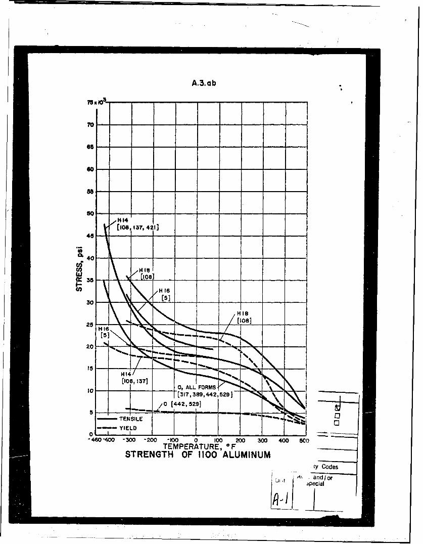
A.3.ab
90 -
6 5 --
50- - - - - -H 14[log, 157, 4213
06 40
I1 35-
/-
/ H 16
30- [513 ] _ -__ "_,\\z55
S0
YIELD j"480-"400 3500 -200 -100 0 100 200 300 400 5C0
TEMPERATURE, FSTRENGTH OF A100 ALUMINUM
CY Codes
-7[317,389,442nd29r
51 /0 [42,529
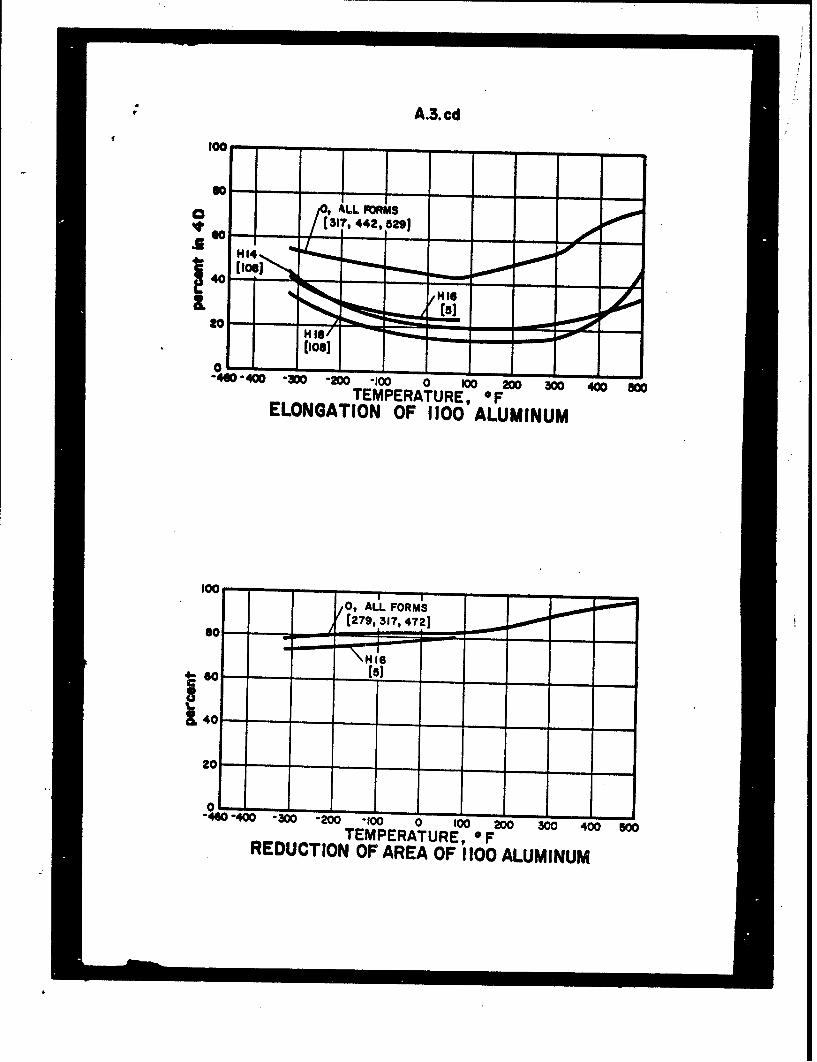
A.3.cd
100- - - - - -f I00
,ALL FORMS[(317, 442, 5291
0 -•,- . - -• - .
40-40O- 300 -20 -100 0 100 200 30 400 800TEMPERATURE, FELONGATION OF 1100 ALUMINUM
$No
0, AU. FORMS([279, 317, 4723
S- = - - - -
OE-- -1 - 1
"440400 "300 .200 -100 0 100 200 300 400 800TEMPERATURE, OFREDUCTION OF 1100 ALUMINUM

FOREWORD
This handbook of data on solid materials at low temperatures
is prepared under the sponsorship of the Air Force Ballistic Missile
Division by personnel of the National Bureau of Standards. Its
preparation is a two year program and deals with physical properties
of certain metals and non-metals over the temperature range minus423"F to plus 500"F.
The materials and properties selected for inclusion in the
handbook are limited by the scope of the contract to those appearing /
in the Index. The materials are mostly those in current use formissile applications at cryogenic temperatures, but a few have been
included because of their potential for such uses. It is hoped that
this compilation of some of the mechanical properties of materialswill assist the designer by making available in one publication
reliable data which have appeared in the literature or which, in some
cases, have not yet been published.
The selection of a material for fabrication of a part can
usually be made in several ways, but very often the simplest method
involves the establishing of some figure of merit for the application
at hand, and comparing materials on the basis of this figure. For
example, double shell, vacuum insulated, cryogenic storage
containers often require tension support members for their inner
shells. Since it is desirable that such members conduct as little
heat as possible into the inner shell from the surroundings of the
vessel, an obvious figure of merit for the material to be selectedis its yield strength divided by its mean thermal conductivity. (The
appropriate yield strength figure is the lowest value for the material
over the temperature range in which it operates. ) When the mostpromising materials have been compared on the basis of these
figures of merit, then the more qualitative aspects can be examined.
These may include such things as the ease of fabrication or theweldability of the material. In some cases, it may even be desirable
to assign arbitrary values to the qualitative properties of thematerials, and so to construct fairly complex figures of merit for
the purpose of material selection.
i. . . . - . .. .. . .. . . . . . .. ..

ii
Following the choice of a proper material, the designer willmake initial stress calculations in order to get an idea of the sizeof the structural components necessary to sustain the-working loads.Here again the mechanical properties of the materials must beknown.
It is to assist these two phases of low temperature equipmentdesign that this handbook is especially presented.
The data are presented with the idea that an engineer whoti making initial calculations on equipment for operation at cryogenictemperatures is more interested in obtaining quickly a definitefigure than he is in evaluating the experimental data given in severaldetailed reports on the same material. The graphs and tablespresented here, consequently, represent an attempt to perform anevaluation of data which have appeared in the literature and to presentthe design engineer with the result. The curves therefore appear aslines representing the mechanical properties as functions of temper-ature, and not as bands representing maximum and minimum valuesreported. There are a few exceptions to this rule, but they weremade only when absolutely necessary.
Such an evaluation process is bound to be somewhat subjective.If it were not, the reduction of data to line graphs could better beperformed by the most convenient digital computer programmed toprovide the best fitting polynomial of degree "n". Unless the datawere weighted judiciously, such a curve would be little more than amathematical delight and perhaps in poor keeping with the known.or suspected behavior of the properties of materials with temper-ature. The curves in this book, therefore, have been constructedfrom data which has been found to be the best documented andthe most consistent with that of other investigators. In most caseswhatever errors remain after such an abridgement will be adequatelycompensated by the designer's use of a "safety factor" in his stressanalysis. Where they are not, and greater confidence is required,the references should be consulted for more detail.
It should be remembered that any reduction of scatteredmechanical properties data to a smooth curve is an attempt torepresent the "most probable" relationship between ordinate andabscissa from among the samples tested. Specific samples may lie

iii
above or below the curve, however, and the discrepancies causedby commercial variation in chemical composition, heat treatment,dimensional and experimental errors, etc., are normally condensedinto a "safety factor" by the designer whereby he sidesteps costlyquality control,- or more complicated mathematics in the case ofcomplex devices. The use of a safety factor is properly the provinceof the design engineer since he knows the use to which the equipmentwill be put, and the reliability desired. It should therefore be subjectto the designer's complete knowledge, and not, as is sometimesthe case, be applied to experimental data by the authors of suchreports as this and the results presented as a table of "permissiblestresses." This not only misplaces the responsibility for safety orreliability, but in complex calculations the safety factor can becompounded unintentionally. The point of mentioning this is merelythat the data in this book should be used with caution for designsin which safety factors must be small (as in cases of restrictedweight or size), since low temperature properties are often sensitiveto variations in thermal and mechanical history and chemicalcomposition which are allowable within commercial specifications.
In addition to these variations, limitations in experimentalaccuracy may account for some of the apparent inconsistencieswhich appear in graphs in this book.
Adjacent to each curve are several numbers in brackets.These numbers correspond to the references in the bibliographywhich will be issued later and indicate the sources of data fromwhich the curve was constructed. In most cases smooth curvesare used to represent the behavior of the mechanical propertiesas functions of temperature. These curves represent interpolationbetween experimental data points as mentioned before. In somecases, however, the data are joined by straight lines, and inter-mediate or end points are indicated. Where this occurs, it isbecause either a scarcity of data or a doubt on the part of theauthors cautioned against drawing a smooth curve.
In general, most of the pertinent information about unusualtest specimens or methods used to obtain the data given in any graphare noted on the graph itself. One omission consistently made,however, is to specify the method by which yield strengths weredetermined. Unless otherwise noted, the yield strength in tension
iv
and compression was found by the 0. 2% offset method. Extremelydetailed information in which only an occasional designer might beinterested can be obtained by reference to the original paper@.
Throughbout the book various symbols are used in order toabbreviate the notes on the graphs. These correspond with usualmetallurgical practice: "OQ & T" means "oil quenched andtempered", "WQ & T" means "water quenched and tempered","ACt" means "air cooled", "RB" and "R.C" mean "Rockwell Bhardness" and "Rockwell C hardness" respectively. Heat treatingtemperatures are given in degrees Fahrenheit. Whenever the met-allurgical condition of the specimens was stated in the literature, itis appended to the curves.
Probably the first thing learned by a newcomer to thecryogenic field about the properties of materials is that somematerials become brittle at low temperatures and are thereforeunusable in many st.:ructural applications at these temperatures.This is true, of course, and the literature is studded with accountsof spectacular brittle service failures which would not have occurredat higher temperatures. There are certain applications, however,in which it would be a mistake to apply the ductility criterion in theselection of a material for low temperature service. Springs arean example. The ductility criterion should not be applied in mostSuch cases, since a smooth coil spring having no re-entrant cornersis carefully designed to act as an elastic member and usually neednot possess any ductility for its satisfactory service. Professor
-Collins at the Massachusetts Institute of Technology, for example, hassuccessfully used carbon steel valve springs in expansion enginesfor the liquefaction of nitrogen and helium.
For most structural applications, however, the engineerwould like some assurance that the material he selects will notbe brittle at the service temperature. If it were, his hardwarewould be liable to catastrophic failure in the event of accidentalimpact or vibration loads at a point where local stresses occurredin excess of those for which he has allowed. "Ductile" materials,of course, are capable of redistributing local stresses in excessof their yield strength by the mechanism of plastic flow. One greatdifficulty, howeiver, has been that of devising a laboratory testwhich will predict satisfactorily whether a material will behave in
v
a ductile or a brittle manner in service. The plastic elongation of
a tensile specimen is not a satisfactory index, since many materialswhich show plastic deformation in a tensile test at a given temper-ature have been known to fail in a brittle manner in service at thesame (or even higher) temperatures. Ordinary low carbon steel,for example, which Eldin and Collins* find to be completely brittlein a tensile test only below 65°K, has a record of many servicefailures at temperatures only moderately below room temperature.Obviously the behavior of a material under the conditions of uniaxialstress present in the usual tensile test does not provide a sufficientlygood prediction of its behavior under multiaxial stress conditions.
The beam impact test, in which a standard-size bar issubjected to a high-velocity blow, while popular because of itsconvenience, is also deficient in some respects as an index ofperformance of a material in service. A correlation has beenobtained between service performance and impact energy for steelsby Jaffee, et al. **, but such a correlation applicable to all materialshas not yet been found. One difficulty seems to be that light metalspay an unjust penalty in the impact test. Magnesium alloys, forexample, exhibit low impact energy, but have been satisfactorilyused in the aircraft industry in structural applications in which theyreceive impact loads. So while the tensile elongation of a materialseems to be too optimistic an indication of service ductility, theenergy absorbed in an impact test seems in some cases to give infor-mation which is too pessimistic. Also, very often the impact energyvalue for a given type of specimen is less important than supplemen-tary information such as 1) whether or not the specimen broke com-pletely in the impact test, 2) how much of the fracture was charac-
terized by cleavage and how much by shear, 3) the trend taken byimpact strength with temperature (some of the lighter metals areinherently lower in absolute value than heavier alloys, but may notdecrease with temperature), etc.
As a simple laboratory test which will provide a suitable
.*Eldin and Collins, Fracture and yield stress of 1020 steel at low
temperature, J. Appl. Phys. (Oct. 1951).
**Jaffee, Kosting, Jones, Bluhm, Hurlich, and Wallace, Impact
tests help engineers specify steel, SAE Journal, March, 1951.

vi
analogy to the service performance of a material, the notch tensiletest is gaining acceptance for some purposes. The test is performedeither at low strain rates in tensile equipment or at high strainrates, usually in impact machines which have been modified forthis use. Just from intuitive reasoning, the ratio of the tensilestrength of a notched bar to that of a smooth bar would seem to bea better criterion for the performance of a material in manystructural applications than either of the previously mentionedtests. "Notches" almost always exist, of course, in any manufact-ured part in the form of weld craters, rivet holes, re-entrantcorners, or simply accidental scratches; and the notch-tensiletest provides an indication of the ability of a material to sustainworking stresses in the presence of such stress raisers. Aproperly designed notch-tensile specimen also contains an areaof bi-axial or tri-axial stress as well, so information can be gainedabout the performance of the material under these conditions.
As a striking example of the different conclusions one woulddraw from information obtained from notched-bar and smooth-bartensile tests, the following are data taken on 0. 020-inch thick type301 stainless steel which had been cold rolled to Z00, 000 psi tensilestrength. The notch depth in the specimens used was 50%, and thenotch sharpness was 0. 0125. *
Test Temperature, Percent Elongation, Ratio of Notched to0 "F Smooth Specimen Smooth Tensile Strength
+350 1 1.05+70 4 1.05
-320 is 0.99
The elongation at +70" and +350" F would indicate less thanacceptable ductility for this alloy, but the ratio of notched to smoothtensile strength remains unity over the temperature range. Thisshows that the material has sufficient ability to deform at the root
*A. Hurlich, J. Watson, Convair Astronautics, private commun-ication. See, for example, G. Sachs and J. D. Lubahn, J. Appl.Mech., 67, A-241 (December, 1945), for an explanation of theterms "notch depth" and "notch sharpness".

vii
of the notch where the stress is greatest, and to redistribute thestress evenly over the load-bearing cross-section.
There are other types of laboratory tests which have beendevised to predict the performance in service of structuralmaterials, each a compromise between simplicity and universalityon the one hand, and degree of applicability to the service require-ment on the other. For the most part, airframe and componentmanufacturers make the compromise in the latter direction. Theirtest specimens consequently consist of subassemblies, completecomponents, or even entire complex assemblies. In industries inwhich weight is not a prime consideration, and larger safety factorscan be used, the tendency is toward the simpler tests. Obviously,economic considerations make the simple experiment the moredesirable, and until a simple test is devised which is a reliableindex of service performan:e, most design engineers will contentthemselves with the less desirable information provided by theusual tensile and impact tests in the first stages of design.
The phenomenon of creep is not usually a problem at lowtemperatures over normally encountered time intervals for any of themetallic materials included in this handbook. The creep behaviorreferred to in the index is that exhibited over very long periods oftime: a year or more. This becomes a difficulty when springs arerequired to retain accurate set points during storage, for example.In this book, therefore, one should expect to find the usual kind ofshort-time creep data only for aluminum alloys and some of thenon-metals, since only these materials exhibit the phenomenonbelow 500*F.
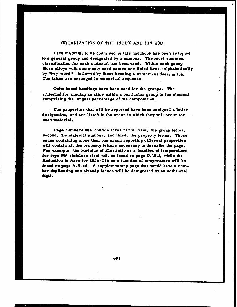
ORGANIZATION OF THE INDEX AND ITS USE
Each material to be contained in this handbook has been assignedto a general group and designated by a number. The most commonclassification for each material has been used. Within each groupthose alloys with commonly used names are listed first- -alphabeticallyby "key-word,- -followed by those bearing a numerical designation.The latter are arranged in numerical sequence.
Quite broad headings have been used for the groups. The• riteriodk.for placing aft alloy within a particular group is the elementcomprising the largest percentage of the composition.
The properties that will be reported have been assigned a letterdesignation, and are listed in the order in which they will occur foreach material.
Page numbers will contain three parts; first, the group letter,second, the material number, and third, the property letter. Thosepages containing more than one graph reporting different propertieswill contain all the property letters necessary to describe the page.For example, the Modulus of Elasticity as a function of temperaturefor type 303 stainless steel will be found on page D. 10. f, while theReduction in Area for 2024-T86 as a function of temperature will befound on page A. 5. cd. A supplementary page that would have a num-ber duplicating one already issued will be designated by an additionaldigit.
viii

INDEX
MATERIAL PROPERTY
A. Aluminum a. Yield StrengthL Tons-502. 356 U. Tensile Strength3. 11004. X2020 c. Elongation5. 20246. 6061 d. Reduction of Area7. 7075
e. Stress Strain DiagramB. Cobalt
1. Elgiloy f. Modulus of Elasticity2. Stellite 33. Stellite 25 g. Impact Energy
C. Copper h. Hardness1. Berylco 252. 70/30 Brass i. Compressive Yield Strength3. Copper
j. Compressive Strength
D. Iron1. Invar 36 k. Shearing Yield Strength2. 34% Manganese Steel3. Ni-Span C I. Shearing Strength4. Vascojet5. 17-4 PH m. Modulus of Rigidity6; 17-7 PH7. A-286 n. Fatigue Behavior8. 3019. 302 o. Creep Behavior
10. 3031I. 304 LC p. Expansivity12. 31013. 321 q. Poisson's Ratio14. 34715. 410 r. Thermal Conductivity16. 41617. 440C s. Mechanical Hysteresis
ix
x
INDEX (continued)
MATERIAL PROPERTY
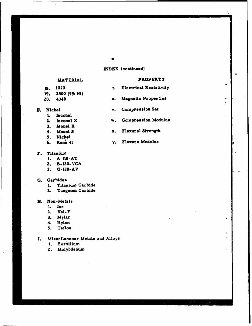
18. 1070 t. Electrical Resistivity19. 2800 (9% Ni)20. 4340 u. Magnetic Properties
E. Nickel v. Compression Set1. Inconel2. Inconel X w. Compression Modulus3. Monet K4. Monet S x. Flexural Strength5. Nickel6. Rene 41 y. Flexure Modulus
F. Titanium1. A-10-AT2. B-120-VCA3. C-120-AV
G. Carbides1. Titanium Carbide2. Tungsten Carbide
H. Non-Metals1. Ice2. Kel-F3. Mylar4. Nylon5. Teflon
1. Miscellaneous Metals and AlloysI. Beryllium2. Molybdenum

A.5. ab
150w 103 - - - - -
140---
130 - - - - - - -
120 --
110 T3 EIOS, 137, 371,443,621,623, 626,628, B0TH CURVES,
100 139 YIELD ONLYI
90 - - -- - - - - - - - - - - - -
70
Go -
50-
T4(1o, 18,31, 116,'-137,437, 443, 474,
40 -477, 4921,544] ,
20 - - - - - - - - - - - - -
TENSILE
inYIELD
0 t*ELL-460-400 -300 -200 -100 0 100 200 300 400 500
TEMPERATURE, FSTRENGTH OF 2024 ALUMINUM
xii
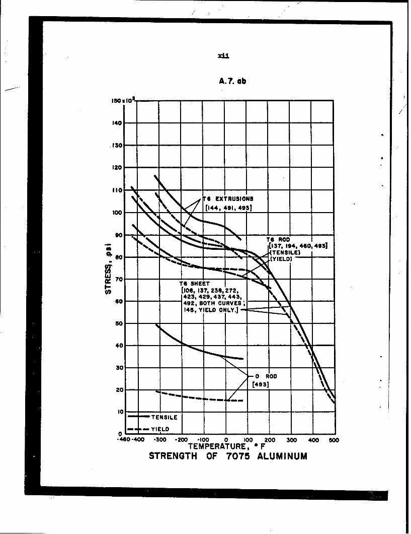
A.?. ab
140- -
.130 - - - - - - -- -
120 -- -
Ito-6G EXTRUSIONS
(13?,194, 460,4931
0 (s1o8,137, 236,272,- -- 492,80OTH CURVES,
30
20
-440 -400 -300 -200 -100 0 100 200 300 400 500TEMPERATURE, OF
STRENGTH OF 7075 ALUMINUM

xiii
A.?. cd
so
50T 6 SHEET1[106, 13", 238, 272, 423,
40 1 429,. 437. 443. 492 .
N .~T 6 ROD'
3 50 -- ':I[37, 460,4968 -- 0 ROD
20
-0 T6 EXTRUSIONS-' •--- (%/ IN 40)1144, 491, 493]
-460-400 -300 -200 -100 0 100 200 300 400 800TEMPERATURE, 0 F
ELONGATION OF 7075 ALUMINUM
60;
40-rT 6 ROD
4-, (30, 31, 460, 4933
20
0
"-460-400 -300 -200 -100 0 100 200 300 400 500
TEMPERATURE,OFREDUCTION OF AREA OF 7075 ALUMINUM

xiv
A.?. f1h
15 le.
06 (30, 10, 194, 460]
-460-400 -300 -200 -100 0 100 200 300 400 G00
TEMPERATURE, *FMODULUS OF ELASTICITY
OF 7075 ALUMINUM
,o . , .. .. I - . ..T6 ROD, CHARPY K T6 ROD, CHARPY V
.0 110 [0,6013?, 446]
-4040-300 -200 -10 0 100 200 300 41 OTEMPERATURE, OF
IMPACT ENERGY OF 7075 ALUMINUM
225
z [4 2, 2721
14
125a1.-
-460-400 -300 -200 -100 0 100 200 300 400 500TEMPERATURE,OF
HARDNESS OF 7075 ALUMINUM

D.6. ab
300 x , I /-.
J/
2210
200
1I o T 1050 SHEET0136, 283, 534,580,
"* 581, BOTH CURVESC. 202, 203, TENSILE ONLY"* IBO
bJn, 140- - -I--
120
I00-
60--
40-
20- - TENSILE
inn mYIELD0 Y I D
-460-400 -300 -200 -100 0 100 200 300 400 500TEMPERATURE, OF
STRENGTH OF 17 -7 PH STAINLESS STEEL
7 7' xvi.
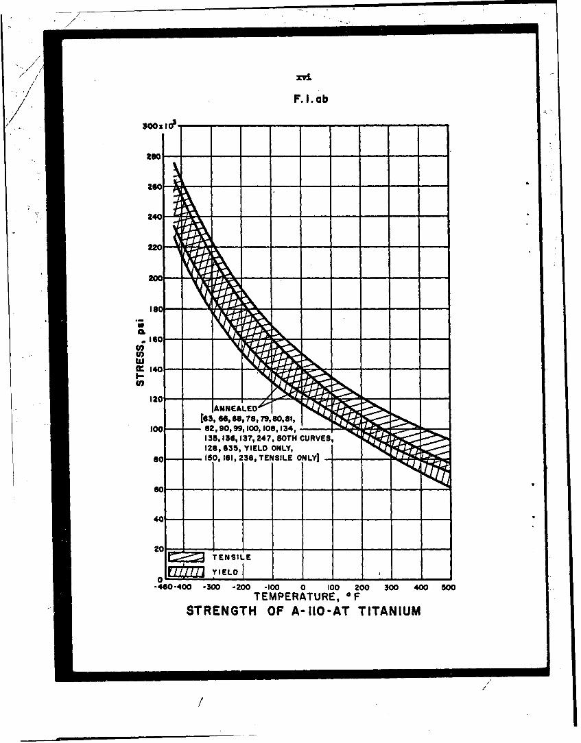
F. .ab24
2U20- - - - - - -
200
BC -
.10
w
ANNEAED'
[63, "e, 68, 78, 79, 90, 81,
0 -82, 90, 99,100, 108,134,135,1I36,137, 247, BOT"HCURVES, • •
128,635, YIELD ONLY,
60 150, 161, 236, TENSILE ONLYI -
TENSILE
0-460-400 -300 -200 -100 0 100 200 300 400 500
TEMPERATURE, FSTRENGTH OF A-11O-AT TITANIUM
/'
/]
xvi±,
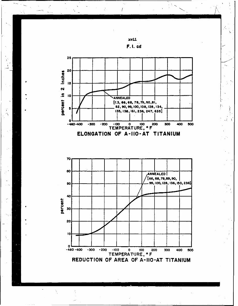
F.I. cd
25
* 20
"-- •ýANNEALED
S~~[(;3, 66,6I8, 78,79,60J,81,, ./ 2,.90, 99. 100, 108, 128,134,
5O, 135, 136, 161, 236, 247, 635] '
L0 C o/I-
- 460-400 -300 -200 -100 0 100 W0O 300 4400 5N0TEMPERATURE, * F
ELONGATION OF A-110-AT TITANIUM
70
6O
s- 9
ANNEALED
/[66, 68, 79, 89, 90,
50 /..99,10l0,128 136, 150, 236).,.
404-
20TEMPRATUE,
0-460o-400 -300 -200o -100 0 100 200 3W 400 500
TEMPERATURE, 0 FREDUCTION OF AREA OF A-110-AT TITANIUM

F. 1. n
z 00
4 '..-0 0 0
4b0
-j~aor, 249 40
hi m
0 0i
00
- -o - - I- 4 >
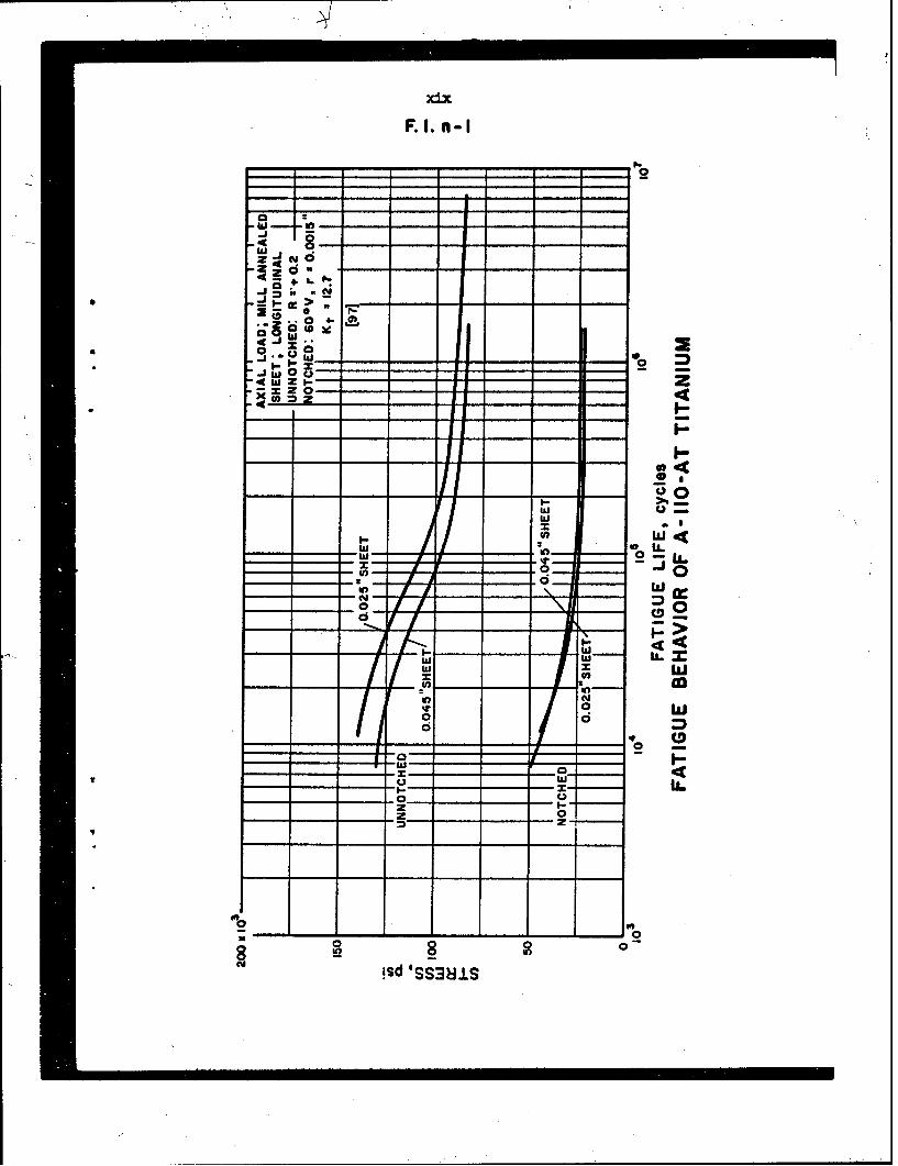
F. 1. n- I
a+
* 0 0
w 0
LLI--c
- .- - 0
U,.
(00 0
- - 0
w0 -
;sd 'SS3jjS

F.3. ab
300x Icp
260 - - - - - - - - -
240- SOLUTION HEAT TREATED FOR I HR.24C' -AT1725 OF, WO, AGED 2 HR. AT1050OF, A C.
220 - - 12
200 FkFhN- - RHOUIO EAT TREA-T D` FORI R
AT 1750OF, WQ, AGED 24 HR. AT-000 0 F, AC.k-106, 132,1331
(62,613, 64,65,66,67, 66,100 - 99, 102, 104,10O5,10S, 107, #30,
136, 244, 247, BOTH CURVES;I,165 TENSILE ONLY.]so -- - - - -
60 -- - - - - - - -
40-
20 - - - - - - - - -TENSILE
0i1nw YIELD-460 -400 -300 -200 -1OO 0 100 200 300 400 500TEMPERATURE,OF
STRENGTH OF C~t-iE2OeAV TITANIUM
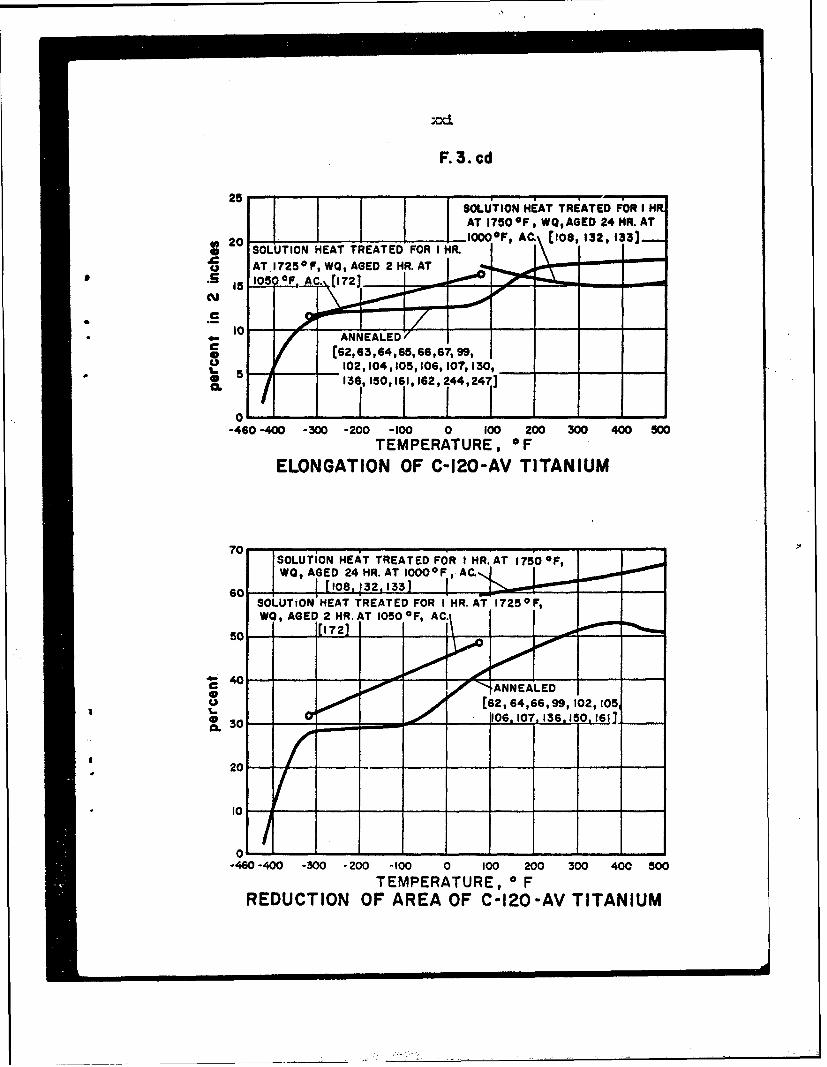
F. 3. cd
25 ~SOLUTION HiAT T.iATED FOR, IR.AT 1750°OF, WO, AGED 24 MR. AT
* SOLUTION HEAT TREATED FOR I HR.AT.1725OF, WO, AGED 2HR. AT
15 105 OF. Ac., (721
ANNEALEDC [62,63,64,65,66,67, 99,
* . 5 13 O150,161,162, 44,247]0.
0-460 -400 -300 -200 -100 0 100 200 300 400 500
TEMPERATURE, OFELONGATION OF C-120-AV TITANIUM
70 SOLUTiON HEAT TREATED FOR I HR. AT 175'0 OF,WO, AGED 24 HR. AT I1000°FI AC.Q
SOLUTION HEAT TREATED FOR I HR. AT 1725 OF,
WO, AGED 2 HR. AT 1050 OF, AC
50 1[1721 1
~40c -- ANNEALEDmu / • [62, 64,66, 99, 102,1,05,
I.Oa 10 6, 107,.136.1 0,161]
C 30
30
-460 -400 -300 -200 -100 0 100 200 300 400 500TEMPERATURE, 0 F
REDUCTION OF AREA OF C-120-AV TITANIUM

A.3. f
is oo - - - /H - 6 - - -
10 -- - -w~
*\ e4421
"460400 -300 -200 -100 0 too 200 300 400TEMPERATURE, OF
MODULUS OF ELASTICITYOF 1100 ALUMINUM
140 ---
,WITH THE EXCEPTION OF DATA AT -424 OF •N H 14,THESE CURVES REFLECT DATA FROM SPECIMENS
A D
H 16, CHARPY K
40 15, 1
20
0
-460-400 -300 -200 -00 0 100 200 300 400 500TEMPERATURE, oF
IMPACT ENERGY OF 1100 ALUMINUM
.1 •

/
A.3.h
E H. 16 [51
40> ol I I - I
C -40 -30 -200 -100 0 W 4-TEMPERATURE, OF
HARDNESS OF 1100 ALUMINUM

A.3.n
30xO -
RECIPROCATING CANTILEVER BEAM25
-
H 14, 106 CYCLES
m C H 14, 107 CYCLES
55
10 - - - - - - - - - - - --
0".460-400 -300 -200 -100 0 100 300 400 900
TEMPERATURE OFENDURANCE LIMIT OF I160 ALUMINUM
/
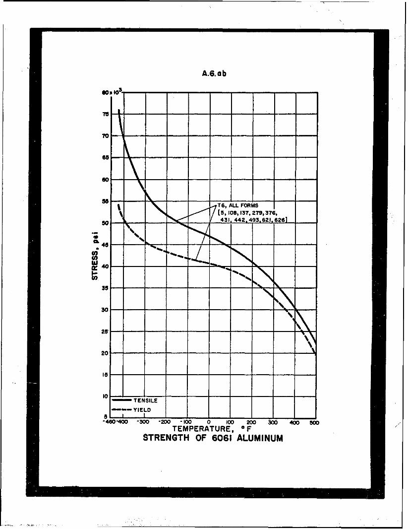
A.6oab
800 103_
75 -
70-
65 -- - - - - - - -
60 ----
aO •• •T6, ALL FORMS
[(5, 108,137, 279,376,50743 442.493,621"6261
35
30
10
1TENSILE-YIELD
5 I"2 400 -300 -200 - - 100 0 100 200 0 400 500TEMPERATURE, -F--
STRENGTH OF 6061 ALUMINUM

A.6.cd
50
40
% I 1T6, ALL FORMS ISC 30 -5, 108,137, 279,376,
"4- 431,442,493,621,6261
320- --20 --- --- "---.•;------------------m,
0 ---
-460 -400 -300 -200 -100 0 100 200 300 400 500TEMPERATURE, OF
ELONGATION OF 6061 ALUMINUM
70-
0 T \T6, ALL FORMS
[5, 279, 49314- 40 -...cUI.
* 30
20
101 f
0"460 400 300 200 -100 0 W00 200 300 400 500
TEMPERATURE, 0FREDUCTION OF AREA OF 6061 ALUMINUM

A.6.fgh
15 lop0
lx10- -
T 6, ALL FORMSC. [51 108, 442,628]
0-W80 -400-300 -200 -100 0 100 200 300 400 BOOS~TEMPERATURE, 0 F
MODULUS OF ELASTICITYOF 6061 ALUMINUM
10
7T61 CHARPY K
*0-460 400 300 -200 -100 0 100 200 300 400 500
TEMPERATURE, o F
IMPACT ENERGY OF 6061.ALUJMINUM
. ~150"
o751---
460 -400 300 200 100 0 100 200 300 400 500TEMPERATURE, 0 F
HARDNESS OF 6061 ALUMINUM
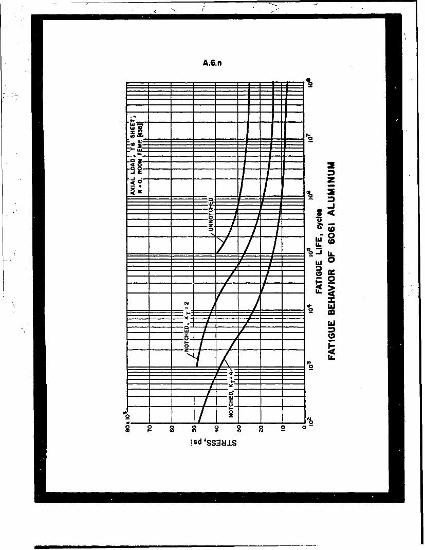
A.6.n
0
00
0
02 0
zz
00 00
n v gI sd SS3MI
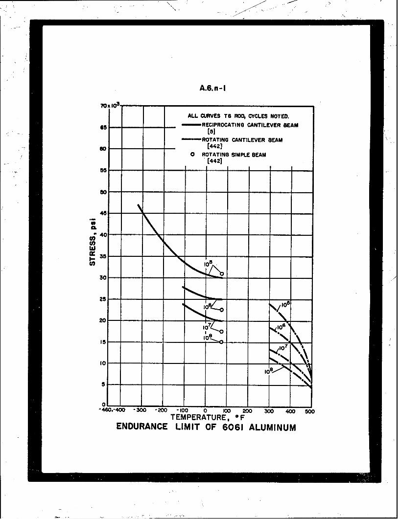
A.6.n-I
70E 103--
ALL CURVES TS ROD, CYCLES NOTED.65 - RECIPROCATING CANTILEVER BEAM
ROTATING CANTILEVER BEAMs-o [442]
0 ROTATING SIMPLE BEAM(442]
"45
a 40
Cl)
35
25: "CDI° - IO,
°~-40 - 00-ZO - -0 -C -0 -0 - O
20 -- -
EIT O 610
IC -
0 -1- ---460.-400 -300 -200 '100 0 100 200 300 400 500
TEMPERATURE, 0FENDURANCE LIMIT OF 6061 ALUMINUM
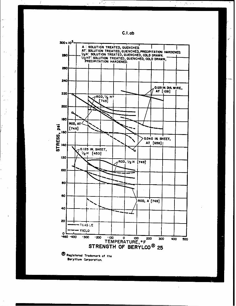
C.ILab
30O 103-A~ SOLUTION TREATED, QUENCHEDýAT: SOLUTION TREATED, QUENCHED, PRECIPITATION HARDENEDi
280 - 1/2 H: SOLUTION TREATED, QUENCHED, COLD DRAWN.I/2HT': SOLUTION TREATED, QUENCHED, COLD DRAWN,PRECIPITATION HARDENEDI
no0 - - - - -
240-
0.125 IN. DIAk WIRE,"%% AT [ 109220
ROD, 1/2 HT(49
ROD,49(74/
TEPEATRE ATSTENT OF749]O@2
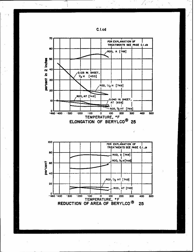
C.I.cd
FOR EXPLANATION OF
TREATMENTS SEE PAGE C.I.abGOI -.
ROD, A 1749]
. 50
SNj 40 '
. 00.125 IN. SHEET,- • 1/2 H/ [453]" 30"%%
,RO0, AT (7497
, -T M ..0.040 6 TN. SHEET,I0 •- • /AT 58s]
80-ROD A (79
0 - R , 1/2 T [74 ,] -
-460 -400 -300 -200 -I00 0 100 200 300 400 - 00TEMPERATURE, OF
ELONGATION OF BERYLCO® 25
100 FOO• EXPLA-NATiON' OF'
TREATMENTS SEE PAGE C.I1. il
S 0 I 'cl. 40 - - - - - - - - - - - - -
S01ROD, 2 HT [749]
----- ROD, AT ([749]
"-460 -400 -300 -200 100 0 100 200 300 400 500
TEMPERATURE, OFREDUCTION OF AREA OF BERYLCO® 25
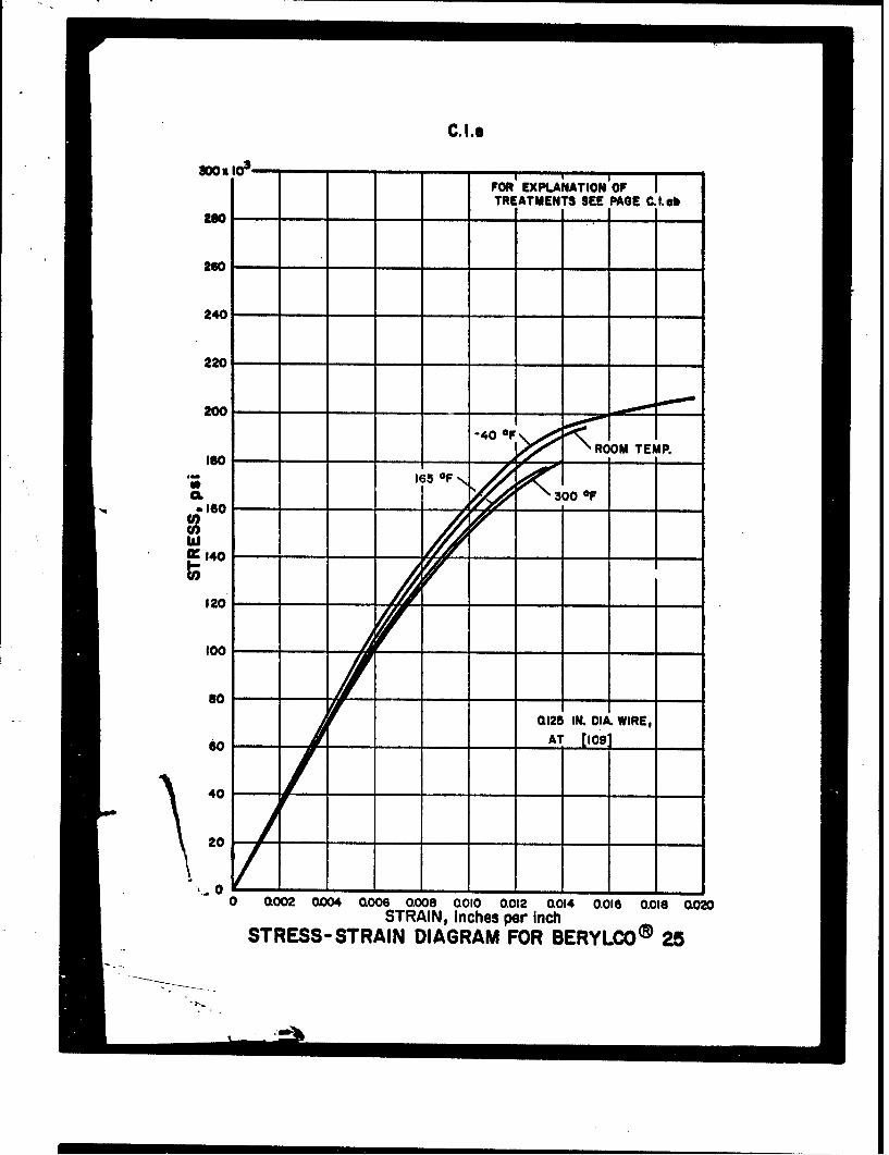
C.I.0
No It -3 -- FOR EXPKA'iATION OF ITREATMENTS SEE PAGE C.I.ob
240
220
200
240- --------------------- ,
ISO-- -165 OF
.. 300 OF
U)
W 11170120 /
100 - --
0125 IN. DIA. WIRE,
AT [1091
40 -- - - -
20
'... 00 0002 OW04 (1006 a008 0010 0.012 Q014 0.016 0.018 0O20
STRAIN, Inches per inchSTRESS-STRAIN DIAGRAM FOR BERYLCO® 25

40.
O.5.g
•H'- 75, COMARPY V
ol-460 -400 -300 -200 100 0 100 200 300 400 900
TEMPERATURE, 0 FIMPACT ENERGY OF 17-4PH
STAINLESS STEEL
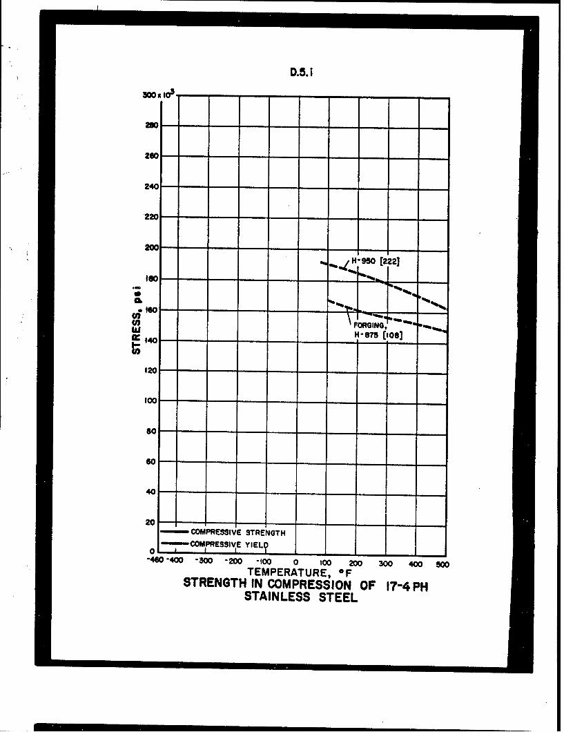
D.5.i
S3 0 0 , 1 0 A . -
260--
240 --
"950 [222]
0.ISO-160 -- %%,.
0 /FORGING,Iii H-em (IoU]
1201.75[10
60
40-
20-zzým COMPRESSIVE STRENGTH
-4'0 -400 -300 -200 100 0 100 20 300 400 50
TEMPERATURE, OFSTRENGTH IN COMPRESSION OF 17-4 PH
STAINLESS STEEL
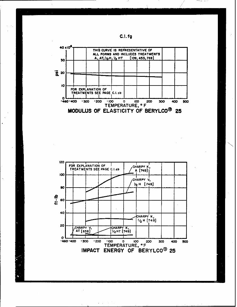
C.I.fg
40 110°THIS CURVE IS REPRESENTATIVE OF
ALL FORMS AND INCLUDES TREATMENTSAt AT,,/2,. , HT [109,453,7491
2020
FOR EXPLANATION OFTREATMENTS SEE PAGE C.I. obo 1 1 1 I I I I
-460-400 -300 -200 -100 100 200 300 4 500TEMPERATURE, 0 FMODULUS OF ELASTICITY OF BERYLCO® 25
N
120 , I - -FOR EXPLANATION OF I I I
TREATMENTS SEE PAGE C.I.Hb A [7491
40
CHARPY V,V2% H 17, 9]
40 - - - - - - - - - - - --- - - - -K-
./,/2 H [74,1
II-460 -400 -300 -200 -100 0 100 200 300 400 500
TEMPERATURE, -FIMPACT ENERGY OF BERYLCO® 25
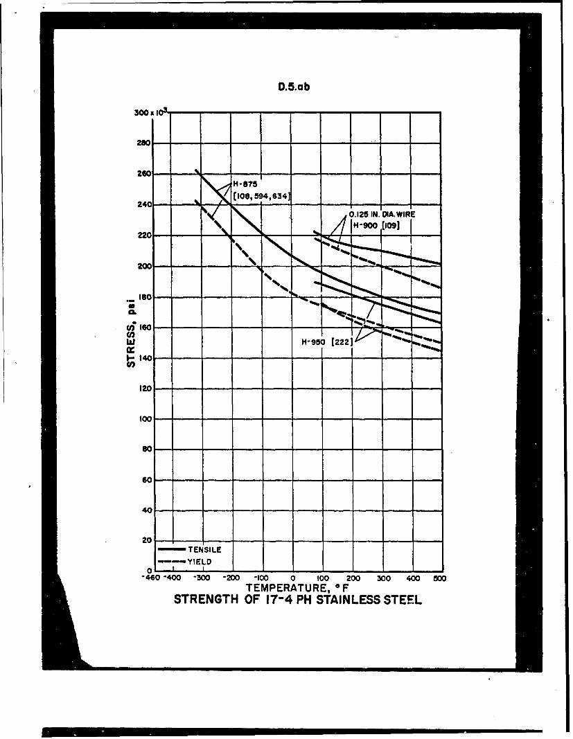
D.5.ab
300 x I- ---
280
260 -- - - -
H-875
[(10, 594,834]
o.125 IN. DA.WIRE
200
ISO 12.... - - - - -
40I - - -.
2 10 -
TE ISL
w 14 H-950.......-
-40-0 30 -0 10010020 30 40 50
60
40
201STENSILE
"-460"400 "300 "200 "100 0 100 200 300 4W0 500
TEMPERATURE, OFSTRENGTH OF 17-4 PH STAINLESS STEEL
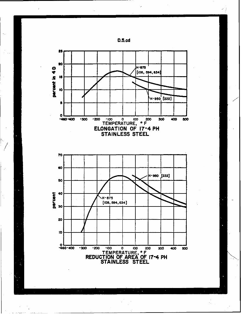
D.5.cd
.2
IO
o18 -,34 H'95O [2221
ol-460-400 -300 -200 -100 0 100 200 300 400 W00
TEMPERATURE, 0 FELONGATION OF 17-4 PH
STAINLESS STEEL
70
60 '-'-'-" - - - -
60---
c \H-875(108,594,634]
20 --
to
0--460-400 -300 -200 -100 0 100 200 300 400 50O
TEMPERATURE, 0 FREDUCTION OF AREA OF 17-4 PH
STAINLESS STEEL

D.5.e
0 it 103 ....
aso
260
2401H 950, COMPRESSION
220 ... ROOM TEMP (222]
200OH-950, TENSIONROOM TEMR [222]
.H"950, TENSION0611 500 OF [2221
0 160
w 140 000
120
100
so
40
20
0 - -- --- --- --- --- - -0 1002 OJO4 0.006 1008 ao0o 0012 0014 0.016 0.018 o020
STRAIN, inches per inchSTRESS-STRAIN DIAGRAM FOR 17-4PH
STAINLESS STEEL

D.8.ab-2
250x 11037
240- --
230~- --
22- 0.032 IN. SHEET, I
210 C-
200-0.032 IN. SHEET, WO
L0.020 IN. SHEET, D
0.062 IN. SHEET
140FULL HARD, COLD ROLLED 40 % RA.TRANS. DIRECTION -ALL CURVES.
130 1 STRESS RELIEVED8 HRS. AT 800F AC F
0 STRAIN RATE 0.02 mid'120 10[ STRAIN RATE 0.005 mIn"I
TO YIELD, 0.05 mirfi TO FAILURE.(286]
110 - -
-TTENSILE
"~ " YIELD
""40 400 300 "200 -100 0 100 200 300 400 500TEMPERATURE, aF
STRENGTH OF AISI 301STAINLESS STEEL
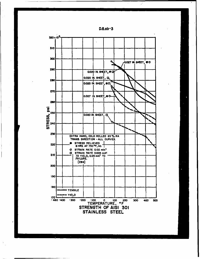
D.8ab-3
320 x 10
310 -- -
300-(027 IN. SHEETI go
SHE
2020I.0HET
(020 IN. SHEET, ,
27 -- - 1I N4CL027 IN. SHEET.9@ 0%
260-14
t250
s? 0.020 IN. SHEET,
it240 - -Q -
230 - - - -- --EXTRA HARD, COLD ROLLED 65 % RATRANS. DIRECTION -ALL CURVES. '4
220 & STRESS RELIEVED-L .SSHRS.AT750OF,AC. -
0 STRAIN RATE 0.02 min"0 STRAIN RATE 0.005 mirrl
210 .TO YIELD, 0.05 mIrVi TOFAILURE.
20-
19 - -
ISO - - -- - - - - -
TENSILE
-,,, YIELD170 - - - - -"
-460 -400 -300 -200 -i00 0 100 200 300 400 800TEMPERATURE, OF
STRENGTH OF AISI 301STAINLESS STEEL

D.8.ab
375 103 - - -. -.- ....
325 - - --
250
225* ANNEALED-
I2 0 0c.- ... .. . .. .-.-.--
175
100.
SO .--.- -r•SL ...-.-..
50 -- LES T
25 TEh SILE-
--- YIELD - - - - - - - -
-460-400 -300 -200 -100 0 100 200 300 400 500TEMPERATURE, OF
STRENGTH OF AISI 301STAINLESS STEEL

D.8ob- I
U~ 0 -b.020 IN: SHEET, /07ltS~TEXTRA, HARD,@ XR HARD 00
270 - -A
260 - - L0020 IN. SHEET,
0.027 IN. SHEET,-250 -- I EXTRA IHARD,*0-Z-
0.020 IN. SHEET,
240 I EXTRA. HARD,9
LONa DIRECTION - ALL CURVES230 0 STRESS RELIEVED
8SHRtAT 750-F, ACI8 STRESS RELIEVED
.- 220- OHKAT 800 0F, ACCl 0 STRAIN RATE 0.02tnlr:1
13 STRAIN RATE 0.005 min-0f210- TO YIELD, 0.05 mint' TO
w ~~FAILURE. L2INSET
w -__ FL HR,_~20FULL HARD: COLD ROLLED 40 % RA__
U)20EXTRA HARD: COLD ROLLED 65 % RA
ISO - -002I.SET
00.032 IN. SHEET,~~FULL HARD, NUV
ISO-0.062 IN. SHEE T
-TENSILE L FULLHARD
170 112 IN HET
!60 -40-0 20t0 10 20 30 0 0
STAINLESS. STEEL,
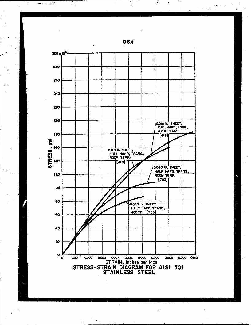
ID,8..
260
240
220
2000.010 IN. SHEET,
FULL HARD, LONG,ROOM TEMP. 001
a160
6 0.010 IN. SHEET,
w FULL HARD, TRANS.,w OM TEMP.\ 1,0ý :140 [1 Y , I EI
", 0.040 IN. SHEET,HALHALF HARD,TRANS
[ 703]
100 -0
so 00 rV, 00- 0.040 IN. SHEET,HALF HARD, TRANS.,
40
20
00 0001 0002 0003 0004 Q005 0.006 0.007 0.008 0009 0010
STRAIN, inches per inchSTRESS-STRAIN DIAGRAM FOR AISI 301
STAINLESS STEEL

D.8.e- I
00 - -
230 - -
260
240 -
220
200
060
a 0.035 IN. SHEET, -S 160FULL HARD, TRANS.
w ROOM TEMP o
(4131140----- - -"0.0 35 IN. SHEET,
FULL HARD LONW.ROOM M .. .
120 -4133
100"so -
60 - -- ---
40-
20 - - - - - -
0 OW 0002 C3 0.04 005 0.006 Q007 0006 oW9 Q010
STRAIN, inches per inchSTRESS-STRAIN DIAGRAM FOR AISI 301
STAINLESS STEEL
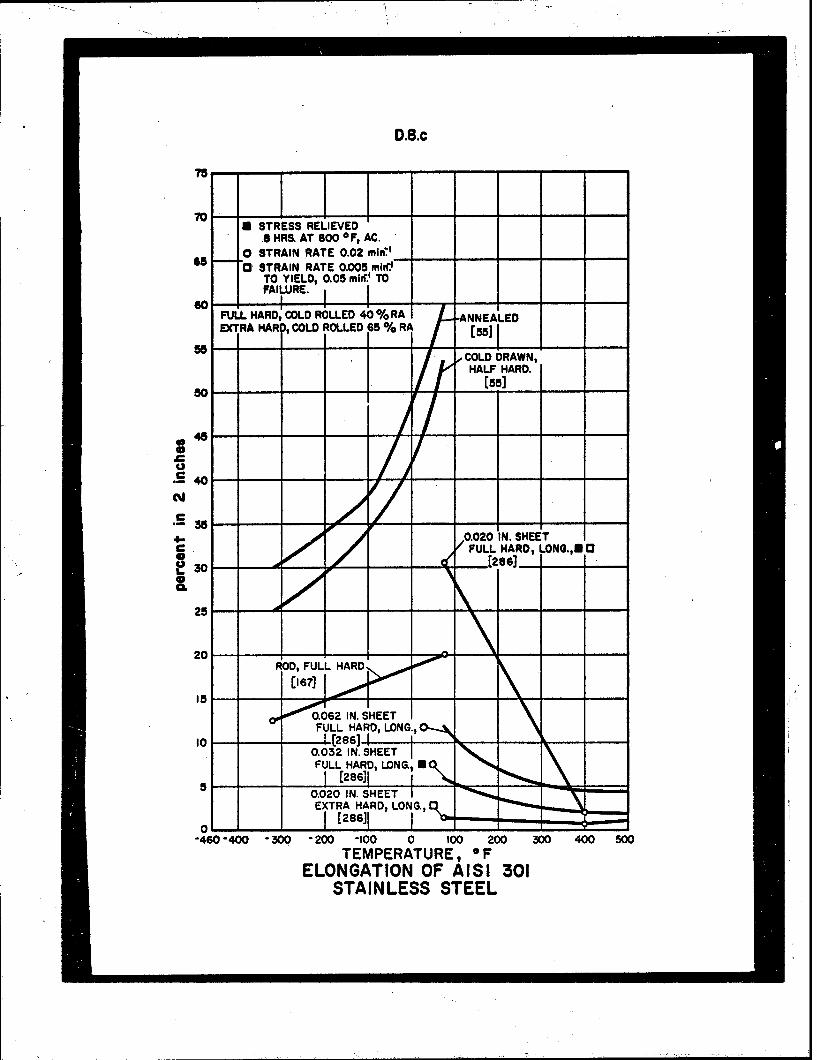
D.8.c
75--- -
70 -1KL0 STRESS RELIEVED
.S HRS. AT 800 OF, AC.0 STRAIN RATE 0.02 mra.
65 0" STRAIN RATE 0.005 miteTO YIELD, 0.05 mirr' TOFAIURE.
FULL HARD COLD ROLLED 40% RA -ANNEALEDEXTRA HARI COLD ROLLED 65 % RA [55-
- -' COLD DRAWN,HALF HARD.
[551
40
N r
S/0.020 IN. SHEETc FULL HARD, NO.aFUL1286] .
SCL
20.
TEE, FULL HARDA
15
O'0.0'--o6 2 1IN. SIME ETI
FULL HARD, LONG.I OFA0S AI [28 l ESS STE0.032 IN. SHEETFU',,LL HARD, LONG, E0.0.020 IN. SETIEXTRA HARD, LONG.,
-460 -400 -300 - 200 -100 0 100 200 300 400 500TEMPERATURE, 0 F
ELONGATION OF AISI 301STAINLESS STEEL

D.8.cd
30 TRANS. DOIRECTION- ALL CURVES.
0 STRESS RELIEVED
25 HiHR AT 800 OF, AC0 STRAIN RATE 0.02 mlri'0 STRAIN RATE 0.005 mlin' TO
YIELD, 0.05 min' TO FAILURE.= 20 .... FULL HARD, COLD ROLLED 40% RA 0.020 IN. SHEET,
M EXTRA HARD, COLD ROLLED 65 % RA FULL HAR, N 0(2861 I
C I 1 - - - - 10.062 IN. SHEET,
10, FULL HARD,
16 0.032 IN. SHEET,0 ~FULL HARD, U" 5I
Q020 IN. SHEET,OLEXTR1 ARD 1,• 1 em
-460 -400 "30 -200 -100 0 100 200 300 400 800TEMPERATURE, OF
ELONGATION OF AISI 301STAINLESS STEEL
100 ...
CO I•WDRAWN,
HALF HARD [55]so coilEO
-460 -400 -300 -200 "I00 0 10O 200 300 400 500TEMPERATURE, OF
REDUCTION OF AREA OF AISI 30ISTAINLESS STEELJ ' I I " I I I I i i i55,1

D.8.fg
/.4
S10.020 IN. SHEET,•FULL HARD, LONG.
40 /STRESS RELIEVED-/ HR. AT 800°OF, AC
FULL HARD •O040 IN. SHEET,20 [HALF HARD
[7031
10
"-460 -40 -300 -200 -100 0 100 200 300 400 500TEMPERATURE, OF
MODULUS OF ELASTICITY OF AISI 301STAINLESS STEEL
130
120 -ANNEALED,
IZOO
"\HAF zHARDI ZOD
90 --- '|
80-
70 1----"460 400 300 200 -100 0 100 200 300 400 500
TEMPERATURE, 0 FIMPACT ENERGY OF AISI 301
STAINLESS STEEL

D.8.i
300 I0 - - - -- - -
2W- -
240-
CLO27 IN. SHEET, •""SEXTRA HARDSK
220-
.; 180 I -
wiQ 0.027 IN. SHEET,0. EXTRA HARDO""
() 0(1032 IN. 'SHEET, i/%W. FULL HARD, IU'
I' 140 --
120 " --
0.032 IN. SHEET,FULL HARD, 0"l -
100-
LONG. DIRECTION, ALL CURVES.- STRESS RELIEVED
S HR. AT 750 OF, ACs STRESS RELIEVED
60 -. 8 HR. AT 800 OF, AC0 STRAIN RATE 0.02 mlIfC
- FULL HARD, COLD ROLLED 40 % RA"EXTRA HARD, COLD ROLLED 65 % RAK
(286)
20 1 ° • I T..S.COMPRESSIVE STRENGTH
"-C,-,COMPRESSIVE YIELD"460-400 "300 "200 .100 0 100 200 300 400 500
TEMPERATURE, OFSTRENGTH IN COMPRESSION OF AISI 301
STAINLESS STEEL

D.8.L
150 10
130-
120
110
1O00
.- 90 -,- - -,
90
U) HALF HARD" - -
Lii 715].
20
IO-'" SH EARIN G S TRENGT H
oi - I-
-460 -0 -200 -- 00 0 I00 200 300 400 500TEMPERATURE, F
SENSTRENGTH IN SHEAR OF AISI 301
STAINLESS STEEL

D.14.ab
33001 x ''
2 --
240
220 -, - -
200
140-
120 NNEALED -
[137, 244, 300,438, COLD DRAWN APPROX. 10%451, 630, OTH CURVES.' ILI193, 380TENSILE ONLY.J
too
so- "-mo 7Lmo
60 - - - - - - - - - -- -
40
20,
TENSILE
- YIELD
"460 -400 -300 "200 -100 0 100 200 300 400 500TEMPERATURE, *F
STRENGTH OF AISI 347STAINLESS STEEL
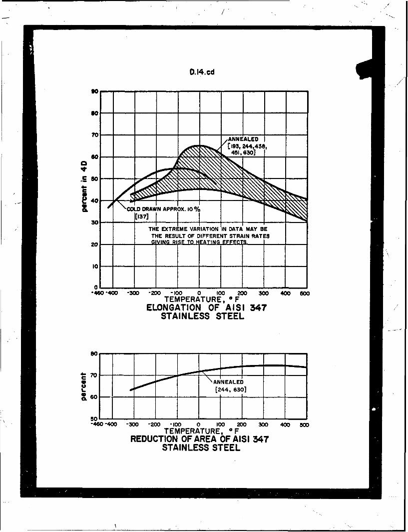
D.14.cd
go-
70
- -- - ANNEALED
40
06 COLD DRAWN APPROX. 10%
30201
"-460 -400 -300 "200 -100 0 100 200 300 400 800TEMPERATURE, OF
ELONGATION OF AISI 347STAINLESS STEEL
so
4 S -70- - " - T - - -
\ANNEALEDU4[244, 6301cl,.60
50L
"460 -400 -300 "200 -100 0 100 200 300 400 500TEMPERATURE, 0 F
REDUCTION OF AREA OF AISI 347STAINLESS STEEL

D.14.e
55
50
C640-ýANAE• ROOM TEMP
d .... ....1438]... . .
30
as
20
I 5 . ..... .
10
5
0
0 OW0 0002 0003 0004 a005 0006 0.007 0.008 0009 0.010STRAIN, Inches per inch
STRESS-STRAIN DIAGRAM FOR AISI 347STAINLESS STEEL
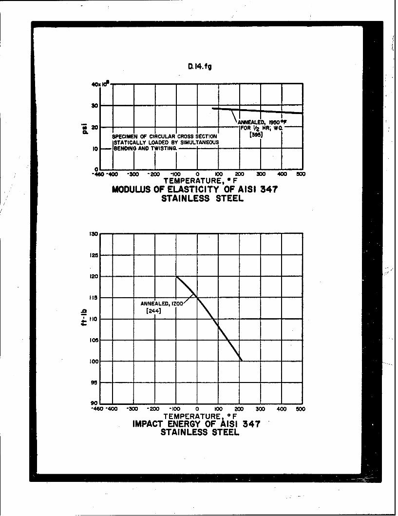
D 14. fg
II
. 0 - - - ANNEALED, 191500F
2 oFOR Va MR, WO.SPECIMEN OF CIRCULAR CROSS SECTION (3951STATICALLY LOADED BY SIMULTANEOUS
10 S BENDING AND TWISTING.
0-'%0 -m -300) - 200 -100 0 100 200 300 400 500
TEMPERATURE, FMODULUS OF ELASTICITY OF AISI 347
STAINLESS STEEL
130
125--
120 .. J
119 5
ANNEALED, IZOD/
.0 (244]110 - --
-- e - - - - - - - - - - - --]
901-460 "400 300 -200 "100 0 100 200 300 400 500
TEMPERATURE FIMPACT ENERGY OF AISI 347
STAINLESS STEEL
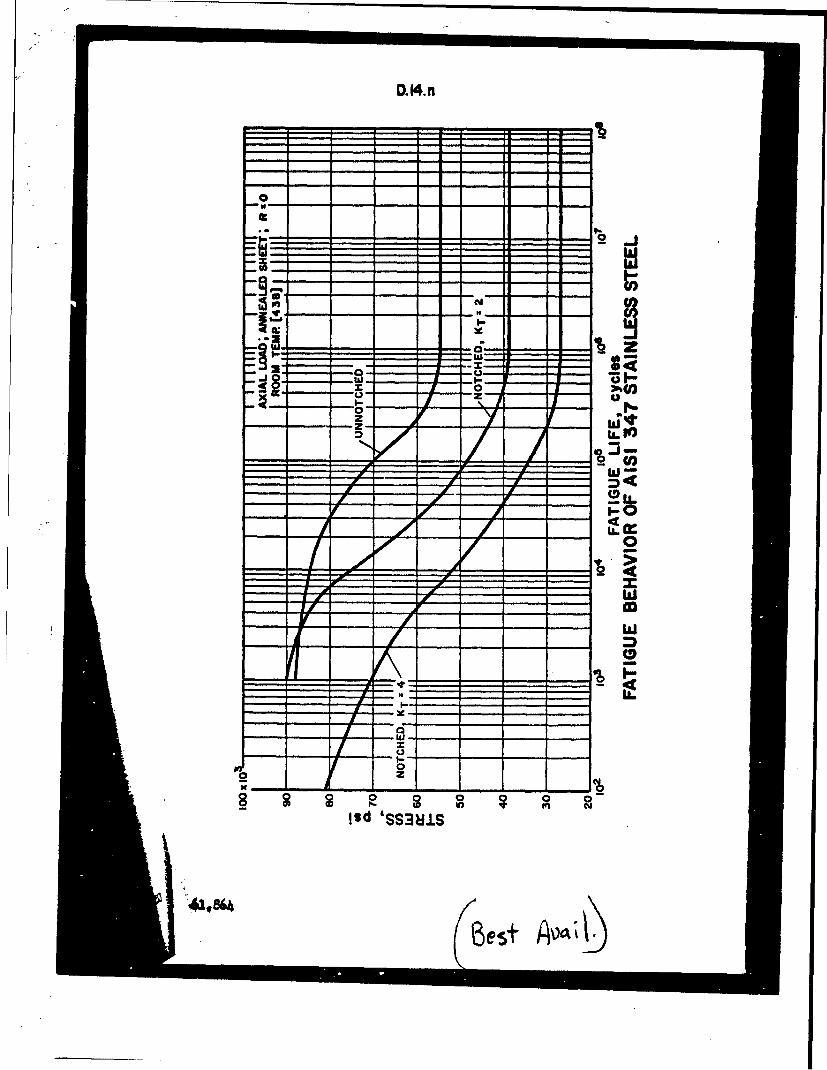
0.14.n
U.1
WI-54c
00-4
J20
lod 'SS381S
16est