ez boatport owner's manual wip - ez dock boatport™ owner’s manual and installation...
TRANSCRIPT

EZ BoatPort™
Owner’s Manual and Installation Instructions for EZ Dock’s EZ BoatPort Models 208015BL, 208015EX, 208015FT, 208100, 208101, 208102, 208104, 208105, 600041, 600042, 600043, 100729, 250050-BK, & 250060
EZD-EZBoatPortMANUAL-2012
For questions about features, operation/performance, parts, accessories or service, call your local dealer. Additional information regarding EZ Dock products can be found online at www.ez-dock.com
TM
The first dock of its kind...The last dock you will ever need®.

2
For more information go to www.ez-dock.com.
General Information and Installation Overview………………………………………...………………...…………3
EZ BoatPort Specifications…………….…….…...…………………………......................................................4
EZ BoatPort Product Line……………………………………………………………………………………………5
Site Conditions and Usage……………………………….….………………………………………………….…12
Model/Serial Number and Hydrophobic Vent……………………………….….………………………………….13
Customer Service Assistance...….…….….………………………………………………………………...……...13
Maintaining your EZ BoatPort……........….……………….……..…………………………………………..…….13
1. EZ BoatPort Installation Methods……………………………………………………………………………...14
1A. EZ Dock Coupler Installation…………………………………………………………………………..14
1B. Installation of the EZ BoatPort to a Floating Dock using a Hinge Kit……………………………16
1C. Installation of the EZ BoatPort with Pipe…………………………………………………………...17
2. EZ BoatPort Usage Options…………………………………………………………………………………….18
2A. Side Extension Installation…..……………………………………………………………………….18
2B. Float Tank Installation………….…………………………………………………………………….20
2C. Side Extension with Float Tank Installation…..……………………………………………...…….22
3. EZ BoatPort Accessories……………………………………………………………………………………….25
3A. Long Bunk Lift Kit Installation………………………………………………………………………….25
3B. Short Bunk Lift Kit Installation…………………………………………………………………………26
3C. Supplemental Flotation Kit Installation……………………………………………………………….27
3D. Keel Roller Installation………………………………………………………………………………….28
3E. Flip-Up Cleat Installation……………………………………………………………………………….28
3F. Standard Winch Kit Installation………………………………………………………………………..29
3G. Large Winch Kit Installation……………………………………………………………………………30
4A. Porting Instructions…………….………………………………………………………………………………...31
4B. Porting Instructions…………….………………………………………………………………………………..32
Sample Configurations……………………………………………………………………………………………….33
Installations…………………………………………………………………………………………………………….35
Warranty……........….………………………...…..…………………………………………….…………………….37
Dear EZ Dock Owner, The EZ Dock team thanks you for your purchase. We know that you had other choices of boat lifts, and we appreciate your decision to purchase the EZ BoatPort. You will find it easy to maintain your EZ BoatPort and to add accessories and other components to your dock in the future. The EZ BoatPort is the most durable and versatile boat lift on the market. We hope that you, your family and your friends will enjoy this boat lift for many years to come. Before you install your new EZ BoatPort, please take a moment to register your dock warranty. You can register online at www.ez-dock.com, by using the warranty registration card provided by your distributor/dealer. To register you will need the serial number off the front of the EZ BoatPort. By registering your product, you will activate your product warranty and thereby protect your purchase against covered product defects. Please feel free to give our EZ Dock customer service department a call with any issues that you may have with your EZ BoatPort. You can reach our customer service department by dialing: USA/Canada: 1-800-654-8168 Int’l: 1-417-235-2223 Europe: +46 (0) 380 47 300
Table of Contents

3
For more information go to www.ez-dock.com.
As with most assembly and installation projects, some tools are required to assemble and install your EZ BoatPort. You may not need every tool listed below for your particular installation, but the following tools are generally helpful in the installation process (for professional installation, call your local EZ Dock dealer): EZ Dock in-water installation tool (9000010) (for EZ Dock mounting in-water assembly) Composite Coupler Installation Tool (900005) 1/2” drive ratchet Socket set (1/2”, 9/16”, 5/8”, 11/16”, 15/16” Hex Drive or 24mm—12 pt) Open-end, boxed-end wrench set (above mentioned sizes) Screwdrivers (#3 Phillips and standard) Pliers Adjustable wrenches Hammer (rubber mallet) Pry-bar (small and large) Rope (minimum 3/8” braided nylon) Power drill & bits Power or Hand Saw Utility knife
GENERAL INFORMATION The EZ Dock system and the EZ BoatPort are uniquely simple, low-maintenance designs that are versatile, safe, and durable. EZ Dock’s patented one-piece, self-floating design is fast and easy to install. Sections come in several sizes with evenly spaced coupler, hardware, and anchor pockets. Once assembled, this system is designed to minimize the amount of flex occurring from stress and loads on the system. The rubber connections will stretch to help the system-, and its attachments-, absorb shock and extreme pressures. Properly installed and maintained, this system will last for years of enjoyable use. IMPORTANT! Assembly, Installation, Maintenance and Safety: You should read these instructions thoroughly, before assembling and installing your EZ BoatPort. Please adhere to all recommendations and cautionary suggestions appearing in this manual and always follow the instructions precisely. Please save these instructions and refer to them as needed for future reference.
ASSEMBLY OVERVIEW
The layout should be planned before beginning to assemble the dock. Make sure the correct tools are available. The system may be assembled on the ground, on open water, or on a sufficiently thick ice sheet. To make
assembly easier, attach pairs of the dock sections together before placing in the water. Verify that all dock sections and hardware are on site and ready for installation.
Recommendations: Attach as much hardware to dock sections as possible before placing the sections in the water. Whenever possible, connections should be made at the shoreline, and the dock should be pushed out into the water.
GENERAL INFORMATION AND INSTALLATION OVERVIEW
Tool Requirements
Drowning Hazard
Swimming under and/or attempting to breathe in cavities under EZ Dock docks and ports while performing in-water installation of docks, ports and couplers can result in accidental drowning and death.
Do not attempt in-water installation without EZ Dock in-water coupler installation tools.
DANGER

4
For more information go to www.ez-dock.com.
EZ BoatPort Specifications
Model Part Number Width Weight Flotation Capacity
EZ BoatPort 208015BL-** 80”
(203.2 cm) 500 lbs.
(226.8 kg) 2000 lbs.*
(907.2 kg)*
Supplemental Flotation Kit
208100 20”
(50.8 cm) 40 lbs.
(18.2 kg) 450 lbs.
(204.1 kg)
Long Bunk Kit 208101 8”
(20.3 cm) 35 lbs.
(15.9 kg) N/A
Short Bunk Kit 208102 8”
(20.3 cm) 33 lbs.
(15.0 kg) N/A
Length
164” (416.6 cm)
40” (101.6 cm)
108” (274.3 cm)
75” (190.5 cm)
Height
15” (38.1 cm)
8” (20.3 cm)
10” (25.4 cm)
5” (12.7 cm)
Standard Winch Kit 100729 9”
(22.9 cm) 7”
(17.8 cm) 20”
(50.8 cm) 38 lbs.
(17.2 kg) N/A
12” Keel Roller Kit 250050-BK 14”
(35.6 cm) 2.5”
(6.4 cm) 2.5”
(6.4 cm) 4 lbs.
(1.8 kg) N/A
Flip-Up Cleat Kit 250060 8”
(20.3 cm) 6”
(15.2 cm) 1”
(2.5 cm) 3 lbs.
(1.4 kg) N/A
EZ BoatPort Float Tank 208015FT-** 111”
(281.9 cm) 80”
(203.2 cm) 20”
(50.8 cm) 240 lbs.
(108.9 kg) 2000 lbs.*
(907.2 kg)*
EZ BoatPort Side Extension
208015EX-** 164”
(416.6 cm) 20”
(50.8 cm) 15”
(38.1 cm) 140 lbs.
(63.5 kg) 500 lbs.*
(226.8 kg)*
H-Connector Kit 208104 15”
(38.1 cm) 13.5”
(34.3 cm) 12”
(30.5 cm) 12 lbs.
(5.4 kg) N/A
T-Connector Kit 204105 7.5”
(19.1 cm) 13.5”
(34.3 cm) 12”
(30.5 cm) 7 lbs.
(3.2 kg) N/A
Manual AC Control Pump Unit
600041 11”
(27.9 cm) 13.5”
(34.3 cm) 25.5”
(64.8 cm) 30 lbs.
(13.6 kg) N/A
Solar 12VDC Control Pump Unit
600042 11”
(27.9 cm) 13.5”
(34.3 cm) 25.5”
(64.8 cm) 30 lbs.
(13.6 kg) N/A
Remote AC Control Pump Unit
600043 11”
(27.9 cm) 13.5”
(34.3 cm) 25.5”
(64.8 cm) 30 lbs.
(13.6 kg) N/A
Note: Due to the rotomolding process, weights and dimensions may vary. * Theoretical flotation capacity. Actual capacity dependent upon weight distribution.

5
For more information go to www.ez-dock.com.
EZ BoatPort - 208015BL-**
EZ BoatPort Side Extension - 208015EX-**

6
For more information go to www.ez-dock.com.
EZ BoatPort Float Tank - 208015FT-**
Long Bunk Lift Kit - 208101

7
For more information go to www.ez-dock.com.
Short Bunk Lift Kit - 208102
H-Connector Kit - 208104

8
For more information go to www.ez-dock.com.
T-Connector Kit - 208105
Standard Control Pump Unit - 600041

9
For more information go to www.ez-dock.com.
Solar Control Pump Unit - 600042
Remote Control Pump Unit - 600043

10
For more information go to www.ez-dock.com.
Standard Winch Kit - 100729
Supplemental Flotation Kit - 208100

11
For more information go to www.ez-dock.com.
12” Black Keel Roller Kit - 250050-BK
Flip-Up Cleat Kit - 250060
12” Entry Keel Roller Kit w/HDW - 250013

12
For more information go to www.ez-dock.com.
Every EZ Dock EZ BoatPort installation is site specific and needs to be configured specifically for the end user’s intended application. Some factors to take into consideration when determining the components necessary for a proper installation include: intended usage, water conditions, soil/bed conditions, and climate conditions. There are simple rules to follow when determining layout configuration.
Be certain that your installation configuration is designed to accommodate the daily intended use of your EZ BoatPort. Please take into account the following:
Commercial application needs
Public access requirements (ADA, CORP, or other)
Private docking needs
Scale of operation and use (size of boats, number of boats, number of people, etc.)
Other special considerations affecting your daily use Be aware of the unique characteristics of the specific body of water and consider how such conditions will affect the installation. Take into account:
Overall area of the body of water
Water depth (at the shore and at the furthest point of the dock from shore) Normal and greatest wave action
Water level fluctuation
Fresh, brackish, or salt-water
Normal and extraordinary ice thickness and movement
Lake bed and soil conditions (sand, rock, mud, etc.)
Usage
For sites with severe wave conditions, docks should be arranged so that pylons are placed parallel to wave action, so that vents are facing against a dock face or towards the shore to minimize excess water collecting in dock sections.
Site Conditions to be Considered
Understand and consider installation/performance requirements, and then evaluate your ability to fulfill them.
Determine whether your installation will be maintained and inspected on a regular basis.
Become acquainted with the normal movement associated with floating structures.
Determine whether you are capable of performing your own installation or whether it is best to hire a professional by contacting your local EZ Dock dealer.
Once you have considered and worked out the issues above, the next step is to select the anchoring method that is best for you. Since no two installations are exactly the same, each and every EZ Dock installation must be designed and configured for the specific and intended application. Installation with an EZ Dock System (Section 1A): When installing the EZ BoatPort on an EZ Dock system,
simply use standard EZ Dock coupler sets to connect the EZ BoatPort to the EZ Dock. (refer to the installation instruction section 1A).
Installation with other floating dock systems (Section 1B): The EZ BoatPort can be attached to other floating docks with the floating dock adapter hinge kit (refer to the installation instruction section 1B).
Installation with Pipes (Section 1C): Anchoring the EZ BoatPort with pipes allows for freestanding installations or installations connected to an existing EZ Dock dock system (refer to the installation instruction section 1C).

13
For more information go to www.ez-dock.com.
Model/Serial Number You should register your EZ Dock product to ensure proper warranty coverage. The location of the serial number may be difficult or impossible to see once installed, so we suggest that you create a record of your serial numbers and corresponding dock sections prior to installation to insure proper identification when filing a warranty claim. The serial numbers can be found on the vertical side wall on the logo end of the dock sections (Figure 1).
Every EZ BoatPort section has a hydrophobic venting insert. The vent is located in one of the front hand hold areas (Figure 2). These vents are designed to reduce the amount of water that may enter the dock, but still allow the dock section to breathe with temperature variation. When possible, these vents should be positioned towards shore and away from prevailing wind/current direction.
Hydrophobic Vent
Figure 2.
Figure 1.
EZ Dock distributors and dealers can provide assistance with:
Features and specifications of EZ Dock’s full line of products Installation information Use and maintenance procedures Accessory and repair part sales Referrals to local dealers
Maintaining your EZ Dock System
Care and Maintenance
Cleaning: Your new EZ BoatPort can be easily cleaned using a brush, mild cleaning agent, and water. For stubborn stains, use a diluted bleach solution. A power washer can be used when convenient. Algae growth at the waterline on the product is normal and will not harm the port.
Ice: The EZ BoatPort floats high enough so that normal ice pressure will not harm the product. However, if the shoreline area has ice pressure pushes, wind blown ice, or other ice flows, the dock needs to be removed or disconnected from the moorings. In these circumstances, pipes or piles should be removed to prevent bending due to ice pressure.
Removal: If the EZ BoatPort is removed at anytime for storage, it should not be dragged over rough gravel or other sharp objects. The EZ BoatPort may be stored outside without any special care when stored on edge or with the walking surface facing up.
Customer Service Assistance:
When calling for service assistance, please know the purchase date, model and/or serial number of your EZ BoatPort. You will also need your serial number for product registration. This information will help us to better respond to your request. If you need replacement parts, contact your dealer to obtain only genuine parts. These parts will fit right and work correctly because they are made with the same precision used to build your EZ BoatPort. To locate replacement parts in your area, call 1-800-654-8168 (US and Canada), 1-417-235-2223 (Africa, Asia or Central or South America), or +46 (0) 380 47 300 in Europe. French speaking residents in Quebec should call 1-800-654-8168. These numbers will put you in contact with your nearest distributor/dealer. You may also locate your nearest distributor or dealer by logging onto our website at www.ez-dock.com.

14
For more information go to www.ez-dock.com.
Helpful Hint: To make assembly and disassembly easier, rub a marina safe lubricant on the coupler rods.
1. EZ BoatPort Installation Methods
The EZ BoatPort mounts to existing or new EZ Dock installations using standard EZ Dock couplers (301100). It can be connected at the front four (4) pockets as shown in Figure 3 and/or the front two (2) side pockets on each side of the EZ BoatPort. Note: For detailed coupler (301100) installation instructions, please see page 15. Tools required: In-Water Installation Tool (900010) Ratchet and socket set Composite Coupler Installation Tool (900005) Screwdrivers (Phillips and standard) 15/16” or 24mm socket Pry-bar (small and large) Hammer (rubber mallet)
Figure 3.
NOTE: 1. All empty or unused coupler pockets should be filled with an EZ Dock pocket filler (201030). 2. When side mounting, it is recommended to utilize both front side coupler pockets along with
an additional dock section in front of the EZ BoatPort.
1A. EZ Dock Coupler Installation (301100)

15
For more information go to www.ez-dock.com.
1. Insert the composite coupler bolt (Item 6) into coupler (Item 5). Align the mark on the head of the bolt so the splines line up into the notched pockets in the coupler.
2. Using a hammer, seat the bolt into the coupler (Figure 4). 3. Install coupler with seated bolt on the in-water installation tool, (Figure 5).
4. Align the EZ Dock dock sections and the EZ BoatPort so coupler pockets are adjacent to each other (Figure 6). 5. Using the in-water installation tool (Item 7), insert the coupler and bolt assembly into the bottom pocket with the bolt pointing upward (Figure 6). 6. Hold the top handle and lower the tool with coupler in the water until the rod is completely below the bottom surface of the dock section. (If the rod hits the dock section the coupler may fall off the tool). 7. While maintaining the proper depth, slide the tool between the dock sections until you reach the pocket to be connected. 8. Pull up on the in-water installation tool to seat the bottom coupler. (NOTE: The EZ Dock and EZ BoatPort must be sitting level on the water and at the same elevation for the coupler to properly seat into the bottom pocket. This may
require a counter balance weight toward the entry end of the EZ BoatPort to offset the weight of the installer who is standing at the seam between the EZ BoatPort and the EZ Dock). The coupler is fully seated in its pocket when the indicator hole on the in-water installation tool (Figure 5) is flush with the top of the dock (you should be able to insert a screwdriver through the indicator hole).
9. While holding pressure, insert the top coupler into the opposing pocket by aligning the hole in the top coupler over the rod and pushing the coupler into the pocket, (Figure 7).
10. Install the coupler nut (Item 4) onto the bolt and tighten until the top of the bolt is 3/8 -1/2” below the top of the nut (do not torque over 15 ft-lb). Due to the security feature on the coupler nut, the composite coupler installation tool (Item 3) is required for tightening. The coupler installation tool is splined on the end to be inserted into the coupler nut and the other end is a 15/16” bolt. This is inserted into a 15/16” socket (Item 2) with ratchet (Item1) for tightening (Figure 7).
11. To release the installation tool, remove pin/screwdriver from the indicator hole and push down tool, sliding it between the docks to begin your next coupler installation.
DO NOT OVER TIGHTEN THE NUT! ( Do not torque over 15 ft.-lbs.)
1A. EZ Dock Coupler Installation (Continued) (301100)
Figure 4. Figure 5.
Figure 6.
Figure 7.

16
For more information go to www.ez-dock.com.
1B. Installation of the EZ BoatPort to a Floating Dock using Hinge Kit (100750 & 100750SS) The 100750 or 100750SS hinge kit is required when anchoring an EZ BoatPort (208015BL-**) at an existing floating dock. This kit can be used either on the front of the EZ BoatPort (Figure 8) or on either set of coupler pockets located on the side of the EZ BoatPort. 1. Measure the freeboard of the fascia of the floating dock where the connection will be made. 2. Determine the best position for the hinge adapter plate (Item 5). The plate can be above (Figure 8),
perpendicular, or directly in front of the hinge adapter bracket. 3. No additional weight should be on the EZ BoatPort while measuring hinge adapter plate location. 4. When attaching to a wooden structure, use carriage bolts (not included) to attach the adapter plate. If attaching
to a steel or aluminum structure, it may be necessary to first attach a 2” X 8” (5cm X 20cm) wooden fascia (not included). When attaching to a concrete floating dock, concrete anchor bolts (not included) may be required.
5. Place two (2) hardware connectors (Item 2) in the two outside top pockets on the EZ BoatPort (Item 1). Place J-hook (Item 3) of floating dock adapters (Item 6) in lower EZ BoatPort pockets and rotate toward the hardware connector, allowing the bolt to go through the slotted hole and secure with nut (Item 6).
6. Float the EZ BoatPort into position and secure the hinge pins (Item 4) and hitch pins (Item 7). Tools required: Ratchet and socket set Open-end, boxed-end wrench set Screwdrivers (Phillips and standard) 15/16” or 24mm socket Pry-bar (small and large) Hammer (rubber mallet) Pliers Tape Measure Drill Drill bits
Figure 8.
NOTE: 1. When side mounting, it is recommended to utilize both side coupler pockets along with an
additional dock section in front of the EZ BoatPort. 2. If side mounting, make sure that the beam of watercraft is not wider than the EZ BoatPort to
avoid any collision with the existing dock and the hull of the watercraft. 3. Make sure bow of watercraft will not hit existing floating dock. If addition length is needed
due to a longer boat, add additional EZ Dock dock sections to front of EZ BoatPort.
17
For more information go to www.ez-dock.com.
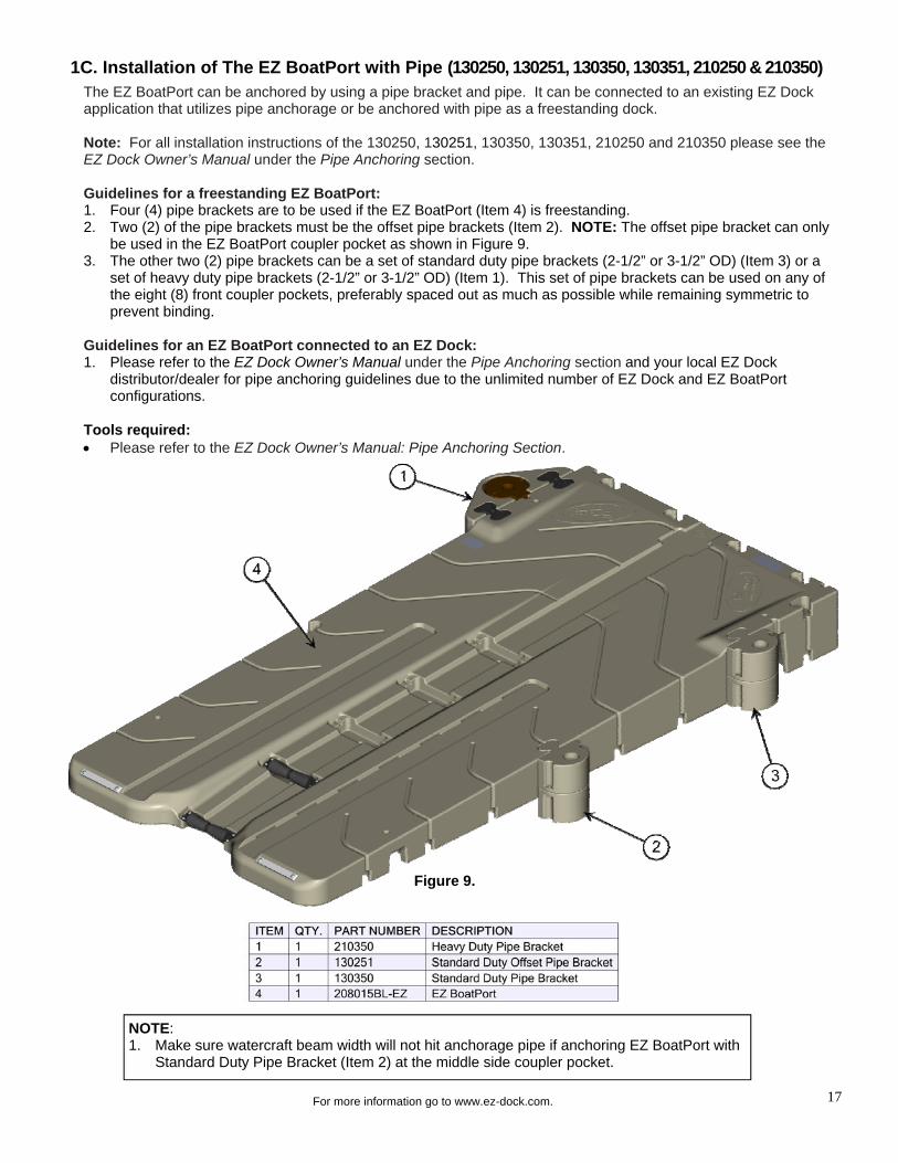
1C. Installation of The EZ BoatPort with Pipe (130250, 130251, 130350, 130351, 210250 & 210350) The EZ BoatPort can be anchored by using a pipe bracket and pipe. It can be connected to an existing EZ Dock application that utilizes pipe anchorage or be anchored with pipe as a freestanding dock. Note: For all installation instructions of the 130250, 130251, 130350, 130351, 210250 and 210350 please see the EZ Dock Owner’s Manual under the Pipe Anchoring section. Guidelines for a freestanding EZ BoatPort: 1. Four (4) pipe brackets are to be used if the EZ BoatPort (Item 4) is freestanding. 2. Two (2) of the pipe brackets must be the offset pipe brackets (Item 2). NOTE: The offset pipe bracket can only
be used in the EZ BoatPort coupler pocket as shown in Figure 9. 3. The other two (2) pipe brackets can be a set of standard duty pipe brackets (2-1/2” or 3-1/2” OD) (Item 3) or a
set of heavy duty pipe brackets (2-1/2” or 3-1/2” OD) (Item 1). This set of pipe brackets can be used on any of the eight (8) front coupler pockets, preferably spaced out as much as possible while remaining symmetric to prevent binding.
Guidelines for an EZ BoatPort connected to an EZ Dock: 1. Please refer to the EZ Dock Owner’s Manual under the Pipe Anchoring section and your local EZ Dock
distributor/dealer for pipe anchoring guidelines due to the unlimited number of EZ Dock and EZ BoatPort configurations.
Tools required: Please refer to the EZ Dock Owner’s Manual: Pipe Anchoring Section.
Figure 9.
NOTE: 1. Make sure watercraft beam width will not hit anchorage pipe if anchoring EZ BoatPort with
Standard Duty Pipe Bracket (Item 2) at the middle side coupler pocket.

18
For more information go to www.ez-dock.com.
2A. Side Extension Installation (208015BL + 208015EX + 208104) The EZ BoatPort Side Extension can be added to one or both sides of the EZ BoatPort, making the lift either 100” wide (with one Side Extension) or 120” wide (with a Side Extension on each side). This will allow for a larger platform that will provide more area for wider boats, additional walking surface, increased flotation capacity and added versatility for a wider array of installations/applications. The H-Connector Kit (208104) is required to attach one EZ BoatPort Side Extension. For watercraft in excess of 3000 pounds the EZ BoatPort side extensions must be used in pairs to ensure proper weight and balance. Note: For ease of installation, Side Extension installs can be done on land with proper equipment utilized to safely lift and move the assembled lift. Make sure to follow these instructions thoroughly. Tools required: EZ Dock in-water installation tool (9000010) Composite Coupler Installation Tool (900005) Ratchet and socket set Open-end, boxed-end wrench set Hammer (rubber mallet) Pry-bar (small and large) First, connect the H-Connector (Figure 10): 1. Slide the H-Insert (Item 2) into the EZ BoatPort (Item 1) rear connector pocket. Make sure the H-Insert is fully
inserted. 2. Secure the H-Connector using the bolt (Item 3) and washer (Item 4) provided. Be sure not to over tighten. A
marine safe lubricant is recommended to prevent galling of the stainless steel bolt.
2. EZ BoatPort Usage Options
Figure 10.

19
For more information go to www.ez-dock.com.
2A. Side Extension Installation (Continued) (208015BL + 208015EX + 208104) Next, attach Side Extension (Figure 11): 1. Slide the Side Extension (Item 1) over the extruding H-Connector (Item 2) and seat into place. 2. Secure the Side Extension using the remaining bolt (Item 3) and washer (Item 4) provided. Be sure not to over
tighten. A marine safe lubricant or anti-seize is recommended to prevent galling of the stainless steel bolts.
Figure 12.
Finally, install couplers (Figure 12): 1. Install the short coupler set (Item 1) located at the middle of the EZ BoatPort, using the EZ Dock in-water
installation tool (9000010). For detailed coupler (301100) installation instructions, please see page 15. 2. Install two (2) long coupler sets (Item 2) located toward the front of the port.
Figure 11.

20
For more information go to www.ez-dock.com.
2B. Float Tank Installation (208015BL + 208015FT + 208105)
Figure 14.
The EZ BoatPort Float Tank can be added to the EZ BoatPort, allowing it to increase the flotation capacity by up to 4000 pounds (depending on the weight distribution). The T-Connector Kit (208105) is required to attach the EZ BoatPort Float Tank. Note: For ease of installation, Float Tank installs can be done on land with proper equipment utilized to safely lift and move the assembled lift. Make sure to follow these instructions thoroughly.
Tools required: Ratchet and socket set Open-end, boxed-end wrench set Adjustable wrenches Power drill & bits Screwdrivers Hammer (rubber mallet) Pry-bar (small and large) First, connect hose (Figure 13): 1. Screw hose fitting adapter (Item 2) into float tank (Item 1) and tighten. It is recommended to use thread seal
tape to ensure proper seal. 2. Insert hose (Item 3) onto the hose fitting adapter on the float tank and secure with hose clamp (Item 4).
Figure 13.
Next, connect pump (Figure 14): 1. Insert the other end of the hose (Item 2) onto the Input/Output Valve on the pump unit (Item 1) and secure with
hose clamp (Item 3).
Note: Items 2, 3 and 4 are included in kit S60040.
21
For more information go to www.ez-dock.com.
2B. Float Tank Installation (Continued) (208015BL + 208015FT + 208105)
Figure 16.
Figure 15.
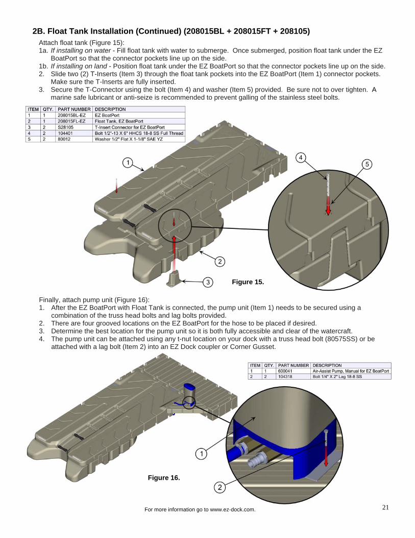
Attach float tank (Figure 15): 1a. If installing on water - Fill float tank with water to submerge. Once submerged, position float tank under the EZ
BoatPort so that the connector pockets line up on the side. 1b. If installing on land - Position float tank under the EZ BoatPort so that the connector pockets line up on the side. 2. Slide two (2) T-Inserts (Item 3) through the float tank pockets into the EZ BoatPort (Item 1) connector pockets.
Make sure the T-Inserts are fully inserted. 3. Secure the T-Connector using the bolt (Item 4) and washer (Item 5) provided. Be sure not to over tighten. A
marine safe lubricant or anti-seize is recommended to prevent galling of the stainless steel bolts.
Finally, attach pump unit (Figure 16): 1. After the EZ BoatPort with Float Tank is connected, the pump unit (Item 1) needs to be secured using a
combination of the truss head bolts and lag bolts provided. 2. There are four grooved locations on the EZ BoatPort for the hose to be placed if desired. 3. Determine the best location for the pump unit so it is both fully accessible and clear of the watercraft. 4. The pump unit can be attached using any t-nut location on your dock with a truss head bolt (80575SS) or be
attached with a lag bolt (Item 2) into an EZ Dock coupler or Corner Gusset.
22
For more information go to www.ez-dock.com.
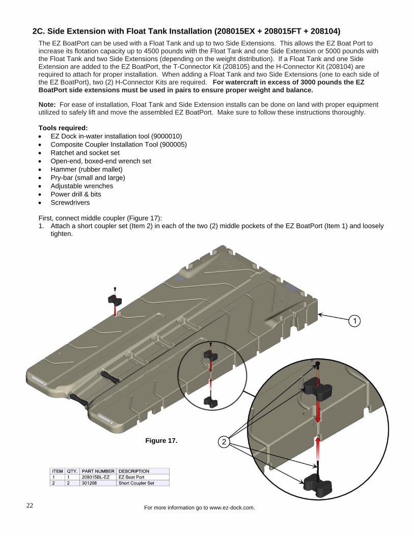
2C. Side Extension with Float Tank Installation (208015EX + 208015FT + 208104)
The EZ BoatPort can be used with a Float Tank and up to two Side Extensions. This allows the EZ Boat Port to increase its flotation capacity up to 4500 pounds with the Float Tank and one Side Extension or 5000 pounds with the Float Tank and two Side Extensions (depending on the weight distribution). If a Float Tank and one Side Extension are added to the EZ BoatPort, the T-Connector Kit (208105) and the H-Connector Kit (208104) are required to attach for proper installation. When adding a Float Tank and two Side Extensions (one to each side of the EZ BoatPort), two (2) H-Connector Kits are required. For watercraft in excess of 3000 pounds the EZ BoatPort side extensions must be used in pairs to ensure proper weight and balance. Note: For ease of installation, Float Tank and Side Extension installs can be done on land with proper equipment utilized to safely lift and move the assembled EZ BoatPort. Make sure to follow these instructions thoroughly. Tools required: EZ Dock in-water installation tool (9000010) Composite Coupler Installation Tool (900005) Ratchet and socket set Open-end, boxed-end wrench set Hammer (rubber mallet) Pry-bar (small and large) Adjustable wrenches Power drill & bits Screwdrivers First, connect middle coupler (Figure 17): 1. Attach a short coupler set (Item 2) in each of the two (2) middle pockets of the EZ BoatPort (Item 1) and loosely
tighten.
Figure 17.

23
For more information go to www.ez-dock.com.
Figure 18.
Next, connect pump, connect hose and attach float tank (Figure 18): 1. Screw hose fitting adapter into float tank and tighten. It is recommended to use thread seal tape to ensure
proper seal. (See Page 20 Figure 13) 2. Insert hose onto the hose fitting adapter on the float tank and secure with hose clamp. (See Page 20 Figure 14). 3a. If installing on water - Fill float tank with water to submerge. Once submerged, position float tank under the EZ
BoatPort so that the connector pockets line up on the side. 3b. If installing on land - Position float tank under the EZ BoatPort so that the connector pockets line up on the side. 4. Slide two (2) H-Inserts (Item 3) through the float tank pockets (Item 2) into the EZ BoatPort (Item 1) connector
pockets. Make sure the H-Inserts are fully inserted. 5. Secure the H-Connector using the bolt (Item 4) and washer (Item 5) provided. Be sure not to over tighten. A
marine safe lubricant or anti-seize is recommended to prevent galling of the stainless steel bolts.
2C. Side Extension with Float Tank Installation (Continued) (208015EX + 208015FT + 208104)
Figure 19.
Next, attach Side Extension (Figure 19): 1. Remove coupler nut and top coupler from the two (2) middle coupler pockets on the EZ BoatPort. The bottom
half of the coupler will remain in place due to the Float Tank. 2. Slide each Side Extension (Item 1) over the extruding H-Connectors (Item 2) and seat into place. 3. Secure the Side Extensions using the remaining bolts (Item 3) and washers (Item 4) provided. Be sure not to
over tighten. A marine safe lubricant or anti-seize is recommended to prevent galling of the stainless steel bolt.

24
For more information go to www.ez-dock.com.
Figure 20.
2C. Side Extension with Float Tank Installation (Continued) (208015EX + 208015FT + 208104)
Figure 21.
Next, install couplers (Figure 20): 1. Install the top couplers and nuts on the short coupler sets (Item 1) located at the middle of the EZ BoatPort. 2. Install two (2) long coupler sets (Item 2) located toward the front of the port, using the EZ Dock in-water
installation tool (9000010). For detailed coupler (301100) installation instructions, please see page 15.
Finally, attach pump unit (Figure 21): 1. After the EZ BoatPort with Float Tank and Side Extension are connected, the pump unit (Item 3) needs to be
secured using a combination of the truss head bolts and lag bolts provided. 2. There are four grooved locations on the EZ BoatPort for the hose to be placed if desired. 3. Determine the best location for the pump unit so it is both fully accessible and clear of the watercraft. 4. The pump unit can be attached using any t-nut location on your dock with a truss head bolt (Item 2) or be
attached with a lag bolt (Item 1) into an EZ Dock coupler or Corner Gusset.

25
For more information go to www.ez-dock.com.
3A. Long Bunk Lift Kit Installation (208101) Bunks can be attached to the EZ BoatPort to keep the hull of the watercraft from rubbing on the port while also stabilizing the watercraft due to any angle of dead rise on the hull. The long bunk lift kit is generally used with flatter bottom boats (dead rise angle of 0-15 degrees) and for boats with a squared bow. 1. Place the long entry bunks (Item 4) in recessed areas on the EZ BoatPort (Item 3) (Figure 22). Each bunk is
symmetrical and has tabs on each side. First, these tabs should be inserted in the tab pockets on the port, then rotate the bunk down towards the port.
2. Secure each long bunk with two (2) washers (Item 2) and two (2) bolts (Item 1) in the slotted holes located at the middle of the bunk.
3. Secure the bunk with the remaining four (4) washers and bolts in the slotted holes located at each end of the bunk.
Tools required: Screwdrivers (Phillips and standard) Pry-bar (small and large) Hammer (rubber mallet)
3. EZ BoatPort Accessories
Figure 22.
26
For more information go to www.ez-dock.com.
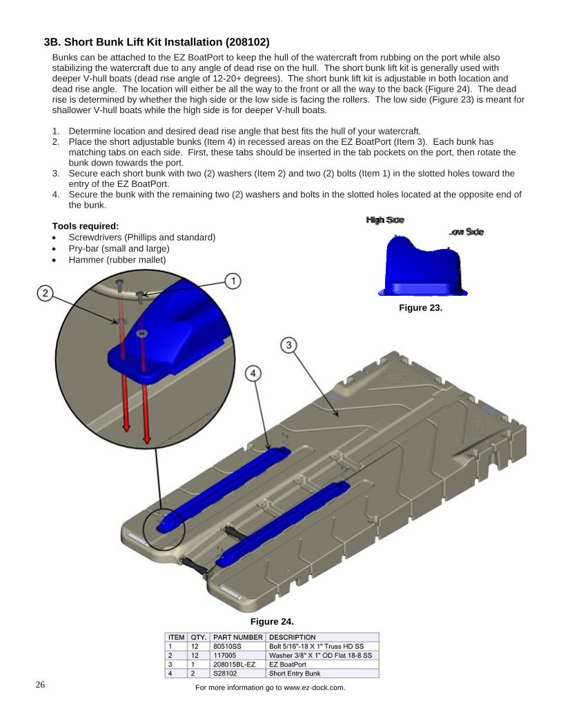
3B. Short Bunk Lift Kit Installation (208102)
Figure 24.
Bunks can be attached to the EZ BoatPort to keep the hull of the watercraft from rubbing on the port while also stabilizing the watercraft due to any angle of dead rise on the hull. The short bunk lift kit is generally used with deeper V-hull boats (dead rise angle of 12-20+ degrees). The short bunk lift kit is adjustable in both location and dead rise angle. The location will either be all the way to the front or all the way to the back (Figure 24). The dead rise is determined by whether the high side or the low side is facing the rollers. The low side (Figure 23) is meant for shallower V-hull boats while the high side is for deeper V-hull boats. 1. Determine location and desired dead rise angle that best fits the hull of your watercraft. 2. Place the short adjustable bunks (Item 4) in recessed areas on the EZ BoatPort (Item 3). Each bunk has
matching tabs on each side. First, these tabs should be inserted in the tab pockets on the port, then rotate the bunk down towards the port.
3. Secure each short bunk with two (2) washers (Item 2) and two (2) bolts (Item 1) in the slotted holes toward the entry of the EZ BoatPort.
4. Secure the bunk with the remaining two (2) washers and bolts in the slotted holes located at the opposite end of the bunk.
Tools required: Screwdrivers (Phillips and standard) Pry-bar (small and large) Hammer (rubber mallet)
Figure 23.

27
For more information go to www.ez-dock.com.
3C. Supplemental Flotation Kit Installation (208100) The EZ BoatPort will sometimes be submerged in the back due to the weight from heavier watercrafts. The supplemental flotation kit will provide 450 lbs. of addition flotation to help prevent submersion of the port. The kit comes with two (2) floats, all hardware and a strap to help secure the floats in rough waters. 1. Once the EZ BoatPort (Item 3) is installed at its desired location,
place the supplemental floats (Item 1) under the port into rear pylons (Figure 25). This can be done by submerging the supplemental floats and pushing them under at the entry of the EZ BoatPort (Figure 26). NOTE: Two people may be needed due to the buoyancy of the supplemental floats.
2. Secure supplemental floats with the strap (Item 2) and two (2) washers (Item 5), one (1) bolt (Item 4) and one (1) nut (Item 6) on each side through the hand hold area thru-holes (Detail A).
Tools required: Ratchet and socket set Open-end, boxed-end wrench set Pry-bar (small and large)
Detail A. Figure 26.
Figure 25.

28
For more information go to www.ez-dock.com.
3D. Keel Roller Installation (250050-BK) Each EZ BoatPort comes from the factory with two (2) keel rollers in the last two roller pockets. Up to three (3)additional rollers can be added to the EZ BoatPort to keep the boat hull from rubbing on the top polyethylene walking surface while also providing easier entering and exiting of the port. The original two rollers should remain in the factory locations while any additional roller(s) can be installed on any of the three remaining roller pocket locations. 1. Determine number of rollers to
be added along with location of the roller(s).
2. Place roller (Item 2) in roller pocket with roller shaft down (Figure 27).
3. Secure roller with four 3/4” bolts (Item 1) using a #3 Phillips screwdriver.
Tools required: #3 Phillips Screwdriver
3E. Flip-Up Cleat Installation (250060) Each EZ BoatPort comes from the factory with a location for an additional flip-up cleat. This cleat is meant to secure the bow of small boats. Longer boats will go past the flip-up cleat making the addition of the flip-up cleat unnecessary. EZ Dock offers two additional cleats (300100 and 300110) for boats that are longer and do not work properly with the flip-up cleat. 1. Place flip-up cleat (Item 2) at
designated location so that the cleat flips toward the entry of the EZ BoatPort (Figure 28).
2. Secure cleat with four 1” bolts (Item 1) using a #3 Phillips screwdriver.
Tools required: #3 Phillips Screwdriver
Figure 28.
Figure 27.

29
For more information go to www.ez-dock.com.
3F. Standard Winch Kit Installation (100729) Although a majority of boats will be able to power onto the EZ BoatPort, there is a standard winch kit available for shorter boats (less than 14’ in length) that either don't have enough power to board the port or choose not to. First, assemble the winch kit (Figure 29): 1. Insert three (3) 1” carriage bolts (Item 4) into the three (3) square holes
on the winch attachment bracket (Item 3) with bolt head facing down. 2. Place black spacers (Item 5) on the carriage bolts and then slide the
ratchet winch (Item 6) over that. 3. Place three (3) washers (Item 2) over the three (3) carriage bolts and
secure with the 5/16” hex nuts (Item 1).
Attach to EZ BoatPort (Figure 30 and Detail B): 1. Once the winch is assembled, place it on the EZ BoatPort by inserting
the winch attachment bracket (Figure 29 Item 3) of the winch assembly (Item 3) into the middle bottom pocket of the EZ BoatPort and rotate it toward the port.
2. Secure the winch kit by placing two (2) washers (Item 2) over the slotted holes and inserting two (2) 1” bolts (Item 1) into the corresponding t-nut locations on the EZ BoatPort.
Tools required: Ratchet and socket set Open-end, boxed-end wrench set Screwdrivers (Phillips)
Figure 30.
Detail B.
Figure 29.

30
For more information go to www.ez-dock.com.
3G. Large Winch Kit Installation (210350 + 100730) Although a majority of boats will be able to power onto the EZ BoatPort, there is a large winch kit available for longer boats (greater than 14’ in length) that either don't have enough power to board the port or choose not to. Note: For longer boats, additional EZ Dock dock section(s) will need to be added to the front of the EZ BoatPort as an extension for the large winch kit to couple to, since the EZ BoatPort is only 14’ 8” long. 1. Couple additional dock sections (Item 3) to the front of the EZ BoatPort (Item 1) (see Section 1A for EZ Dock
Coupler Installation instructions). Note: Other dock sections may be used in place of two 40” x 5’ dock sections (Figure 31).
2. Couple 3-1/2” heavy duty pipe bracket (Item 4) to the front of additional dock sections directly in front of the two (2) middle pockets on the EZ BoatPort (Figure 31). For installation instructions of heavy duty pipe bracket please see the EZ Dock Owner’s Manual under the Pipe Anchoring section.
3. Insert the shaft of the deadweight insert bracket with winch (Item 5) into the heavy duty pipe bracket. For installation instructions of deadweight insert bracket with winch please see the EZ Dock Owner’s Manual under the Deadweight Anchoring section.
Tools required: Please refer to the Section 1A and EZ Dock Owner’s Manual: Pipe and Deadweight Anchoring Sections.
Figure 31.
NOTE: 1. Make sure area in front of the EZ BoatPort is clear of all
obstructions and people while porting your watercraft.

31
For more information go to www.ez-dock.com.
4A. Porting Instructions
#1 Idle Up to the EZ BoatPort entry Idle the nose of the watercraft to the stern keel roller of the EZ BoatPort entry. Come to a complete stop and allow the watercraft to center itself, with the keel in-line with the center of the rollers. -Do not attempt to port while people or pets are standing on the port or adjacent dock sections.
-Driver and passengers must be properly seated while porting. -Porting speed should not exceed 2 mph. -Follow your boat owner’s manual for safe and proper boating methods.
IT IS NOT RECOMMENDED OR NECESSARY TO BUILD UP MOMENTUM TO DOCK ON THE EZ BOATPORT.
#2 Ease into the Throttle After the complete stop and once the watercraft is in-line with the rollers, simply ease into the throttle and allow the machine to roll forward into the proper position. There is a learning curve with this technique and it may take you several attempts to get the watercraft into the proper position. With practice you can perfect your docking procedure.
#3 Roll Aboard & Power Off When docking is complete, your watercraft should be completely out of the water and stable on the port with the power turned off. The watercraft should be secured to the port when not in use with the motor raised out of the water to prevent any algae growth.
The EZ BoatPort is a simple drive-on, push-off/motor-off method of dry docking your watercraft. The self floating EZ
BoatPort moves with the changing water levels and protects your watercraft from wind, wave, or other environmental
conditions. The EZ BoatPort comes from the factory with two adjustable rollers in a common usage position. However,
you may need to make minor roller adjustments by moving or adding rollers. It is very important to ensure that the
watercraft enters the port and launches with the weight distributed on the rollers and/or bunks (optional) and not
rubbing on the polyethylene port walls. The rollers/bunks should be arranged/added accordingly for optimum results.
Launching your watercraft should require only minimal effort and one person should be able to push the watercraft
back into the water or lower the motor and power off. If your watercraft is difficult to launch, seek help and/or contact
your local dealer for roller set-up/bunk options. Do not try to launch a “stuck” watercraft by yourself.

32
For more information go to www.ez-dock.com.
4B. Porting Instructions with Float Tank
#1 Idle Up to the EZ BoatPort entry Idle the nose of the watercraft to the stern keel roller of the EZ BoatPort entry. Come to a complete stop and allow the watercraft to center itself, with the keel in-line with the center of the rollers. -Do not attempt to port while people or pets are standing on the port or adjacent dock sections.
-Driver and passengers must be properly seated while porting.
-Porting speed should not exceed 2 mph. -Follow your boat owner’s manual for safe and proper boating methods.
IT IS NOT RECOMMENDED OR NECESSARY TO BUILD UP MOMENTUM TO DOCK ON THE EZ BOATPORT.
#2 Ease into the Throttle, Roll Aboard & Secure
After the complete stop and once the watercraft is in-line with the rollers, simply ease into the throttle and allow the machine to roll forward into the proper position. There is a learning curve with this technique and it may take you several attempts to get the watercraft into the proper position. With practice you can perfect your docking procedure. Once the watercraft is all the way on the EZ BoatPort, put the throttle in neutral tie up the boat so it is secure and does not roll off the EZ BoatPort. Roller and bunk adjustments may be required if watercraft rolls off.
#3 Power Off & Activate Pump Unit When the watercraft is fully secure and stable on the EZ BoatPort, turn off the engine. Next, activate the control pump unit to lift the watercraft out of the water. Turn off the control pump unit whenever the bottom of the EZ BoatPort is flush with the water’s surface or when you see bubbles forming at the rear of the Float Tank. The watercraft should be secured to the port when not in use with the motor raised out of the water to prevent any algae growth.

33
For more information go to www.ez-dock.com.
Sample Configurations

34
For more information go to www.ez-dock.com.
Sample Configurations

35
For more information go to www.ez-dock.com.
Installations

36
For more information go to www.ez-dock.com.
Installations

37
For more information go to www.ez-dock.com.
Flotation (8 Years) - EZ BoatPorts are warranted against cracks, breakage, leaks, and ultraviolet deterioration caused
by defects in material and manufacturing workmanship for a period of eight (8) years from the date of purchase.
Hardware and Accessories (1 Year) - Hardware and accessories are warranted against defects in material and
manufacturing workmanship for a period of one (1) year from the date of purchase.
These Limited Warranties specifically do not cover damages to EZ Dock products caused by: improper installation;
use inconsistent with EZ Dock’s instructions and product specifications; vandalism; severe weather and natural
disaster; impact by watercraft, ice, falling trees, floating debris, and other foreign objects; animals or aquatic life;
unauthorized product modification and attachment; and improper repair.
If an EZ Dock product fails under normal use and within the applicable warranty period, Buyer must submit a written
claim to EZ Dock at 878 East Highway 60, Monett, MO 65708 USA. Claims must identify the failed product(s),
describe the claimed defect(s), and include copies of dated proofs of purchase/receipts from an authorized EZ Dock
reseller.
Upon receiving sufficient proof of covered product failure, EZ Dock will, in its sole discretion, either repair or replace
failed products within a reasonable time after notice, and ship, at Buyer’s expense, repaired and/or replacement
products to the site. “Repair” may be limited to providing a repair kit to Buyer. Costs related to the removal of failed
products, and the installation of repaired and/or replaced products shall be at Buyer’s expense.
Warranty periods begin on the date of purchase from an authorized EZ Dock reseller. Repaired and replacement
products are warranted only for the balance of the original limited warranty period. These limited warranties extend
only to the original Buyer of products from an authorized EZ Dock reseller (“Original Purchaser”). Warranties are not
transferable to anyone who subsequently purchases products from the Original Purchaser, or to any subsequent
purchaser.
In order to ensure proper warranty coverage, Buyer should activate these Limited Warranties by properly registering
the purchase of EZ Dock products within thirty (30) days of the date of purchase via the Registration Card provided in
EZ Dock’s Owner’s Manual, or by registering online by going to www.ez-dock.com, clicking “Customer Service” and
then clicking “Product Registration”.
Buyer, by acceptance and use of these limited warranties, waives any rights it would otherwise have to claim or assert
that these limited warranties fail of their essential purposes. Buyer agrees that venue for any court action to enforce
these limited warranties shall be in Barry or Greene Counties in the State of Missouri.
THE FOREGOING LIMITED WARRANTY IS THE SOLE AND EXCLUSIVE WARRANTY FOR SELLER’S
PRODUCTS, AND IS IN LIEU OF ALL OTHER WARRANTIES, EXPRESS OR IMPLIED, IN LAW OR IN FACT.
SELLER SPECIFICALLY DISCLAIMS ALL OTHER WARRANTIES, EXPRESS OR IMPLIED, INCLUDING,
WITHOUT LIMITATION, ALL IMPLIED WARRANTIES OF MERCHANTABILITY AND FITNESS FOR A
PARTICULAR USE OR PURPOSE, AND ANY IMPLIED WARRANTIES ARISING OUT OF COURSE OF DEALING
OR PERFORMANCE OR TRADE USAGE. SELLER SHALL NOT BE LIABLE FOR ANY INCIDENTAL,
CONSEQUENTIAL, EXEMPLARY, SPECIAL, OR PUNITIVE DAMAGES, OR ANY LOSS OF REVENUE, PROFIT
OR USE, ARISING OUT OF A BREACH OF THIS WARRANTY OR IN CONNECTION WITH THE SALE,
INSTALLATION, MAINTENANCE, USE, OPERATION OR REPAIR OF ANY PRODUCT. IN NO EVENT WILL
SELLER BE LIABLE FOR ANY AMOUNT GREATER THAN THE PURCHASE PRICE OF A DEFECTIVE
PRODUCT.
Limited Warranty:

©2011 EZ Dock, Inc. EZ Dock is a member of the PlayPower family of companies, which also includes Miracle Recreation Equipment company, PlayPower LT Inc., SoftPlay, L.L.C., HAGS, RSS, Records, and SMP.
EZD-EZBoatPortMANUAL-2012
The first dock of its kind...The last dock you will ever need®.
www.ez-dock.com
USA/Canada: 1-800-654-8168
Int’l: 1-417-235-2223
Europe: +46 (0) 380 47 300