eyi-,,l - american radio history: documents from the ... · other advantages, however, compensate...
TRANSCRIPT

DECEMBER 1945 /eyi-,,L
. . CONTENTS . .
VOL. 2, No. 5
PT Modulation for Multiple Transmission Electronic Industries 1
A Simple Co -Axial Switch Radio News 4
Automatic Fader Electronics 7
Electronic Navigator Radio -Craft 9
Antenna Construction Hints C Q 11
Photoelectric Cells Service 15
Don't Let "Intermittents" Get You Down! Radio Service Dealer 20
Radio Ahead on the Handie-Talkie_-Domestic Commerce 27
N. Y. Navy Yard's Quiet Room Communications 33
What's Being Read This Month 35
PUBLISHED BY REEVES -ELY LABORATORIES, INC. www.americanradiohistory.com
THE RADIO ENGINEERS' DIGEST JOHN F. C. MOORE, Editor
Copyright 1945 by Reeves -Ely Laboratories, Inc.
Vol. 2, No. 5 December 1945
Published monthly at New York, N. Y., by Reeves -Ely Laboratories, Inc., comprising the following operating divisions and subsidiaries: AMERICAN TRANSFORMER COMPANY, NEWARK, N. J. HUDSON AMERICAN CORPORATION, NEW YORK, N. Y. REEVES SOUND LABORATORIES, NEW YORK, N. Y. WARING PRODUCTS CORPORATION, NEW YORK, N. Y. THE WINSTED HARDWARE MANUFACTURING COMPANY, WINSTED, CONN..
For free distribution to our friends in the radio and electronics industries
Editorial Office, 25 West 43rd Street, New York 18, N. Y.
Printed by Criterion Products Corporation, New York, N. Y., U. S. A.
www.americanradiohistory.com

PT MODULATION FOR MULTIPLE TRANSMISSION
Reprinted from Electronic Industries
Time of occurrence of carrier pulses is advanced for positive and retarded for negative portions of the signal wave
AMPLITUDE modulation appeared to many persons to be the only imaginable
method of varying electric currents to reproduce speech or music until Major Armstrong advanced and popularized frequency modulation. Now that frequency modulation has been with us for a number of years, it appeared that all possible parameters of an electric wave had been explored with respect to their adaptability to the needs of modulation.
However, with the ending of the war still a third method of modulation, utilizing variations in time, has been removed from the secrecy list. Technical details con- cerning its basic principle and the methods by which it can be adapted to com- munication uses have been revealed by engineers of the Federal Telephone & Radio Corp.
0 Ñ C Dw 0- 0-x a 0- j_
TIME AXIS < J Sau
SEC
\ i J -+I A- I p SEC.
A 1300 me carrier generated in a lighthouse type of tube working into cylindrical resonators is turned on and off producing sharp pulses at intervals as shown. Modulation makes the pulse occur a little early or late. Pulses are not heard due to high repetition rate
Stated briefly, the new method permits the transmission of intelligence by means of a series of pulses of about half a microsecond duration, each separated from the other by a time interval of about five microseconds. Their time of recurrence can be advanced or retarded over a range of approximately one microsecond. This new scheme has been called Pulse Time Modulation.
In translating the positive and negative variations of an ordinary alternating current wave into pulse time modulation, changes of time of occurrence of the pulse
Copyright 1945, Caldwell -Clements Inc., 480 Lexington Avenue, N. Y. C.
(Electronic Industries, November 1945)
www.americanradiohistory.com

2 THE RADIO ENGINEERS' DIGEST DECEMBER
in one direction correspond to positive halves of the alternating current while changes of time in the other direction correspond to negative halves. The amplitude of the current wave is translated into magnitude of time displacements, while the frequency of the alternating current wave is translated into frequency with which the time displacement of a pulse moves forward* and backward.
In this system of modulation no significance is attached to the exact shape of the pulse or to its amplitude. In fact the amplitude is made uniform by an am- plitude limiting circuit. The steepness of the wave front of the pulse, however, that is its rise time and its decay time are of importance in determining the signal to noise ratio and the fidelity of reproduction. Therefore, since a steep wave front re- quires a wide band of frequencies for its accurate transmission, pulse time modula- tion is definitely a wide band system requiring a carrier in the ultra or super high frequency range.
Fortunately, however, it is not necessary to devote an entire band of frequencies to the transmission of one message at a time. Since the message, as pulse time modu- lated consists of a series of pulses five microseconds apart it is perfectly possible to intermingle several messages and transmit them all at the same time. Thus pulse No. 1 would be used for message No. 1 while pulse No. 2 is used for message No. 2. Pulse No. 3 would again revert to message No. 1. The break time involved is so short that no effect could be noted by a listener. The company has established experimental circuits transmitting twenty-four conversations all at the same time. Other tests have been made with as many as 250 messages going out simultaneously.
ROTATING BEAM (APERTURE PLATE
L_, 1 e ,.-.1 o J
-I o J
ELECTRON GUN DEFLECTION PLATES COLLECTOR SEGMENTS
When received, the pulses are impressed on the grid of an electron gun which is- normally biased to extinction. The beam, unblocked, rotates in proper position for given signal
In frequency band utilization, this time modulation system is less efficient than either amplitude or frequency modulation. In fact studies, made by the company's engineers indicate that in transmitting three -kilocycle telephone speech messages in a three -megacycle band of frequencies only 150 messages could be transmitted by time modulation, while frequency modulation would permit the transmission of 350 messages and amplitude modulation 750 messages. These figures are based on equal signal to noise ratios at the output of the receiver.
Other advantages, however, compensate for this inefficient frequency band usage. The limiting factor in amplitude modulation systems is the distortion intro- duced by the non -linearity of the tube circuits. Likewise in frequency modulation systems distortions are introduced by the frequency selectivity of the resonant cir- cuits. In pulse time modulation, however, neither of these types of distortion can occur and the addition of more repeaters in a relay chain does not increase the dis- tortion. This obviously provides the system with a considerable advantage in the construction of radio relay chains. Furthermore, the super high frequency carrier circuit being modulated only by being switched on or off to create the pulses can be of an extreme simplicity of design not possible with other systems.
The system was originally patented by A. H. Reeves of Standard Telephones and Cables Ltd. of London, an International Telephone and Telegraph Corp., af- filiate and by E. M. Deloraine of the Federal Telephone Laboratories and has been worked on by other affiliated engineers, notably Mr. E. Labin, and others.
www.americanradiohistory.com

1945 PT MODULATION FOR MULTIPLE TRANSMISSION 3
In the experimental equipment set up by the Federal Telephone Laboratories at 67 Broad Street, a 1300 -megacycle carrier is utilized, being radiated from a simple dipole and beamed by means of a parabolic reflector eight feet in diameter. The high frequency oscillations are generated by means of a 2C43 lighthouse tube in- serted in the end of cylindrical circuit elements.
In the receiving set the time modulated pulses are translated into ordinary amplitude modulation for the operation of a loudspeaker by means of a new tube named the Cyclophone. This tube has some of the elements of an ordinary cathode ray tube being equipped with an electronic gun and a double set of electrostatic deflection plates.
By means of an ordinary circular sweep circuit the beam issuing from the electron gun is made to follow a circular path. The target end of the tube differs from that of an ordinary cathode ray tube, however, in that there is a metal plate with a number of radially disposed slits, equal in number to the number of messages which are to be transmitted simultaneously. Behind this plate with the slits, another plate is mounted as a target for the cathode rays.
A normally negatively biased control grid blocks the cathode ray beam except when one of the time modulated pulses arrives. Depending upon where the cathode ray beam is directed with respect to one of the slits at the time when the unblocking pulse arrives there is a variation in the amount of cathode ray beam current passing through this slit and impinging upon the target dynode. By this means time vari- ations are translated into amplitude variations. For ordinary telephone circuits th cathode ray beam is rotated at 8,000 revolutions per second and for a 24 circuit transmission there are 25 slits in the cyclophone (one of them being used for a marker or synchronizing pulse) .
At the transmission end amplitude modulated speech signals are changed into pulse time modulated signals by a tube similar to the cyclophone called the Cyclo- odos. In this tube the radially disposed slits of the cyclophone are tilted at an angle with respect to the radius of the slitted plate. The cathode ray beam rotates as in the cyclophone but in this case variations in the amplitude of the modulating current cause variations in the radius of rotation of the beam. Since the slits are tilted at an angle the time when the beam crosses the open face of a slit changes either forward or backward according as the radius of rotation of the beam changes.
To find new facts of the physical world, to extend the limits of knowledge, is a for. ward step in creating More Goods for More People at Less Cost.
GENERAL ELECTRIC COMPANY Postwar Research Program
www.americanradiohistory.com
A SIMPLE CO -AXIAL SWITCH Reprinted from Radio News
By Edward Burgess
A simple method to overcome the problem of cost in the use of co -axial Feeders for amateur antennas
ONE of the greatest deterrents to the use of co -axial line as an antenna feeder is the realization that large amounts are needed to feed the two or more an-
tennas in use at most stations. If some method were evolved to switch a common feeder at will, more amateurs would practice this method of feed.
Trial of conventional methods of switching (using relays or ordinary switches results in failure) as the characteristics of the co -ax are materially altered when the live lead is brought into the open, as is necessary in this type of switching.
What is needed is some means of preserving the characteristic impedance of the line at the switching point. Reason dictates some form of enclosed switch, for this purpose, that will continue the line in a form that will appear for all practical pur- poses to be unbroken.
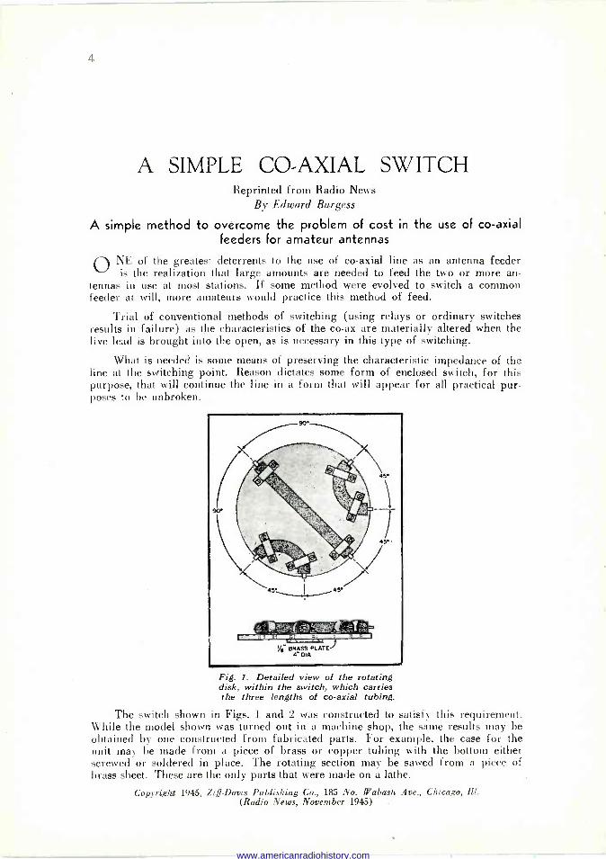
Fig. 1. Detailed view of the rotating disk, within the switch, which carries the three lengths of co -axial tubing.
The switch shown in Figs. 1 and 2 was constructed to satisfy this requirement. While the model shown was turned out in a machine shop, the same results may be obtained by one constructed from fabricated parts. For example, the case for the unit may be made from a piece of brass or copper tubing with the bottom either screwed or soldered in place. The rotating section may be sawed from a piece of brass sheet. These are the only parts that were made on a lathe.
Copyright 1945, Ziff -Davis Publishing Co., 185 No. Wabash Ave., Chicago, Ill. (Radio News, November 1945)
www.americanradiohistory.com

A SIMPLE 'CO -AXIAL SWITCH 5
Details of the rotating section may be seen in Fig. 1. A brass plate about four inches in diameter and one eighth inch thick is used for the base. Short lengths of concentric line, constructed of copper tubing with an inside diameter of five six- teenths inch, have concentric centers made from No. 12 wire which is supported on the conventional ceramic spacers. The ends of the No. 12 wire are allowed to project slightly from the ends of the tube, and are flattened in order to pass between the switch contacts. The lengths of concentric tubing are fastened in place by means of small straps which in turn are screwed to the base by means of 4-36 screws.
A length of one quarter inch shaft is fastened rigidly to the base by means of a flange or swedging to permit ,the plate to be rotated from outside. As laid out in the drawing, the switch has three positions, but this may be varied to suit the constructor.
The antenna feeder from the transmitter connects to the center right hand con- nector, while the antenna leads from the three antennas connect to the other three connectors. As the switch is rotated to the left, the various sections of concentric line within the switch line up between the main connector and the -three antenna con- nectors in turn. Examination of Figs. 1 and 2 will show how this is accomplished.
Fig. 2. Cutaway view of the completed switch, showing method of assembly.
The case for the unit was turned from a piece of solid brass. However, it could just as well be made from tubing, or possibly a heavy, metal can of the proper size may be obtained. The one described has walls about three sixteenths inch thick and one inch in height. Amphenol type SO -239 co -axial sockets are fastened around the periphery of the case in the proper positions to contact the rotating lengths of con- centric line within the case. A clearance ho!e five eighths inch in diameter should
www.americanradiohistory.com

6 THE RADIO ENGINEERS' DIGEST
be drilled in the case at the exact center of each connector. In addition, the case should be filed down slightly in order that the connectors may fit well on the case.
Each connector is modified before being mounted, by soldering the contact from a conventional band switch to the center connector of the fitting. Care must be ex- ercised in this soldering to assure the contact lining up with the rotating stubs inside the case.
It is essential that there be as little clearance as possible between the rotating stubs and the case, to keep the impedance of the lines low and assure a good match. It is suggested that the stubs be made slightly long and then fitted into the case by filing. The outer conductor of the stubs should come very close to the walls of the case as the unit is rotated.
A detent from an old band switch was used to afford proper positioning of the rotating disk. The detent in this case had the detents spaced 90 degrees apart, and additional holes were drilled midway between these to furnish positions spaced 45 degrees. The detent is fastened to the case by means of spacing studs and 6-32 ma- chine screws tapped into the case. By using a detent of this nature, single hole mount- ing of the entire unit may be obtained.
In most cases, two of these units will be needed. One may be mounted near the operating position to enable various transmitters to be switched to the line, while the other is mounted at some remote point, possibly in the attic. In any case the second one should be located at a point that will allow fairly short leads to the antennas.
If the second switch is mounted in an inaccessible position, some means of re- motely controlling it will be necessary. Probably the simplest is to obtain a tuning motor of the type used on motor -tuned broadcast receivers. This motor may then be geared to the shaft of the switch and remotely rotated into position. Any of the con- ventional methods of stopping the motor at a predetermined position may be used.
In the event that a motor driven switch is used, it will be advisable to remove the detent spring from the switch as it will not be needed and will only serve to make the motor load heavier.
In a civilization making such full use of applied science, you have to run fast to stay where you are. If you want to move ahead, you have to run still faster.
E. C. AUCHTER
www.americanradiohistory.com

7
AUTOMATIC FADER Reprinted from Electronics
By Dan Hunter, Chief Engineer, Station WMAL Washington, D. C.
THE device to be described automatically fades a program either completely or
partially in or out, at predetermined rates, without the use of motors. The only moving parts consist of three relays, and individual fade-in and fade-out timing is easily adjusted.
The automatic fader is used to fade the nemo, a remote or network program for a local broadcast, or to join a remote or network program already under way. In the studio, it is also convenient for announcing a remote program. These oper- ations involve strict cooperation between the master -control operator and the an- nouncer unless the program is routed through a studio having a studio operator. This close cooperation demands the type of attention very difficult to achieve in any master control.
CIRCUIT The automatic fader was designed to operate from the nemo and announce tall;
lights plus an installed fade key and tally. As shown in Fig. 1, the fader is essentially an amplifier adjusted for zero gain, with time -delayed bias for control. The am- plifier tube is biased to cutoff for complete fade-out, at an intermediate point for partial fade-out or in, and normal for complete fade-in. The bias is obtained from the two potentiometers in the bleeder circuit.
500 -OHM LINE
ANNOUNCE TALLY
NEMO TALLY' 0.
Fig. 1. Vacuum -tube circuit for complete or partial automatic fading of programs
Two variable timing controls are included (slotted shaft for screwdriver adjust- ment I, one for complete fade-out and one for complete fade-in. Timing of a com- plete fade is adjustable from 1 to fifteen seconds. The timing for the background level or partial fade is fixed at approximately two secónds.
The 6C5 is operated at a plate current of 0.5 to 0.6 ma to obtain a smooth fade. This quiescent point places the operation of the tube slightly above the point where Copyrighted 1945, (all rights reserved) by McGraw-Hill Publishing Co., Inc., 330 W. 42nd St., N.Y.C.
(Electronics, October 1945)
www.americanradiohistory.com

8 THE RADIO ENGINEERS' DIGEST
the amplification begins to vary. This imposes a definite limitation on the maximum permissible input level at which the fader may be operated without distortion. The input is 10,000 ohms bridging, while the output is 500 ohms. The fader and its power supply were mounted on 3.5 -in. rack -mounting panels.
At WMAL, the fader is in the nemo circuit, as shown in the block diagram of Fig. 2. The input of the fader is bridged across the nemo line and the fade relay switches either the nemo or the fader to feed the equipment. This switching can be done any time during a program provided a relay with grounding resistors is used. At WMAL an Automatic Electric relay is used, with 50,000 -ohm resistors from all contacts to ground.
REMOTE LINE REGULAR
NEMO RELAY
FADE RELAY
NEMO TALLY FADER
OUTPUT
FADE kEY AND TALLY
ANNOUNCE TALLY
Fig. 2. Essential elements of the auto- matic fader system
The relay L-2 which gives complete fades obtains its battery from the nemo tally light. This was done so that the fader would always be ready to perform. If the nemo is down, the fader is ready to fade in and vice versa.
The partial fade or background -level relay L1 connects to the battery supplying the announce tally through a contact on relay L_. This allows a background level only when both announce and nemo are set up. Since the tally lights and set-up but- tons are on the announcers switching, console, (delite), the fade key and tally were also placed on the delite. This enables the announcer to completely fade in or out a program or announce over a background level without an operator.
OPERATION
If a fade is desired, the fade key is turned on; the fade tally gives indication. When nemo is released, the program is faded out, or if nemo is set up, the program is faded in. If announce is set up at the same time, then the program is either faded in or out but to a background level.
It was found that a partial fade of 10 db of tone (500 cycles) gave a good back- ground level. The level is adjustable to -58 db when using the circuit shown in Fig. 1.
A man can fail many times, but he isn't a failure until he begins to blame somebody else. JOHN BURROUGHS
www.americanradiohistory.com

9
ELECTRONIC NAVIGATOR Reprinted from Radio -Craft
More important to the safety and speed of navigation than any other
single invention is this new application of radar
FIRST OF the many peace -time applications of radar is an "electronic navi- gator" which can detect through darkness, fog and storm the position of any
above -water obstacles, lighthouses, shorelines or other ships. The instrument, which works along the lines of the Plan Position Indicator described in the October 1945 ssue of Radio -Craft, is so sensitive that it can detect metal objects as small as ordinary buoys. A ship, instead of lying outside a harbor for days, waiting for fog to lift, can navigate up the channel by the buoys on each side, meanwhile "see- ing" any other craft in the same area.
Dr. W. R. G. Baker, General Electric vice president in charge of electronics, who had much to do with the development of television in its present form, predicts that the new device will revolutionize "thick weather" navigation, providing the mariner with an instrument to plot a safe course, even though his normal visibility is, strongly limited by natural conditions.
A working demonstration of the apparatus, held recently in Long Island Sound, showed how, in the dead of night, it is possible for a ship to operate safely and accurately through any kind of thickened overcast condition, with the radar mech- anism giving the ship's navigator a bird's-eye view of the surrounding waters, his own ship being always in the center of the field.
During the demonstration in the waters off Long Island, such objects as other ships, channel markers, lighthouses and land masses were shown in their rel- ative positions, and both distance and bearing were automatically plotted on the face of the viewing screen. The distance of objects from the ship was shown in true proportion, being measured by a series of concentric "marker rings" electron- ically superimposed on the picture screen. According to General Electric engineers, the measurement of distance so given is accurate to the point of one percent.
Basis of the "electronic navigator," is a rotating antenna, located on the top deck of the ship and analogous to a searchlight, in that it sends out beams to locate obstacles in the ship's path. The difference, however, is that beams from the radar antenna, which are actually powerful radio microwaves, are capable of penetrating tog or any other atmospheric conditions without . hindrance. They are sent out as "pulses" or surges of extremely short duration and at a very rapid rate.
As the radar waves locate an obstacle in the surrounding waters, they bounce off and are scattered, no matter of what material the object is. Some of these echoes- or scattered waves-will return to the rotating antenna, which also acts as the receiving antenna during the time intervals between the outgoing pulses. After being amplified, these echoes are made to appear as bright spots on the face of a
cathode ray tube, which is somewhat similar to a television screen tube. The image
Copyright 1945, Radcraft Publications, Inc., 25 West Broadway, N. Y. C. (Radio -Craft, October 1945)
www.americanradiohistory.com
10 THE RADIO ENGINEERS' DIGEST
thus formed gives the operator a "radar picture" of the obstacle, and the marker rings tell him how far away it is.
By controlling internal circuits, the operator may change the scale of the field to cover either a 2-, 6-, or 30 -mile radius. Thus, when a ship is sailing in the open sea, the operator will use the 30 -mile range until an object approaches to within 6 miles. Then, by turning a knob on his radar set, he is immediately presented with a larger scale chart, the outer radius of which is 6 miles. For very close work another turn of the knob provides a 2 -mile radius chart on which objects may be observed down to about 200 yards.
Radar waves sent out iron, the ship's antenna travel with the speed of light - 186,000 miles per second - and therefore require only about a millionth of a second to make a round trip to an object 200 yards away. Since the measure of distance to an obstacle is given with extreme accuracy by the marker circles, the system must be able to measure time down to one hundred -millionth of a second.
In 1943, more than four million gross tons of cargo space were lost on the Great Lakes alone as the result of fog. Out of this, two million tons were lost through serious and hitherto unavoidable accidents such as collisions and groundings. The major part of lost cargo space was caused by fog delays. In 1943, as many as 100 boats at a time were fog -bound at the Soo Locks. Adverse conditions such as these sometimes delayed vessels as much as 30 hours at a time.
The new electronic device will permit the lake navigator to maneuver and direct his ship with utmost safety - in the thickest weather, in the heaviest storm and static, in darkness - or in any combination of all these. Under any adverse weather condition, it will enable the navigator to locate ships, buoys, icebergs, derelicts, and shore lines. It will help him locate river mouths, break -waters, docks and bridges. During storm and blizzard, it will enable him to hug a lee shore and pro- ceed safely, even at times when the time-honored method of echoing the sound of ship's whistle against shore becomes ineffective. The cramped quarters, short runs, and - on the Great Lakes -frequent fogs or storms, make the electronic navigator even more valuable for inland navigation than for deep -water shipping.
Despite the complexity of circuits within the radar system, which such accu- rate timing makes necessary, demonstrators declared that sets are as easy to operate as a large home radio receiver. A few minutes' instruction will enable an operator to grasp the fundamentals of operation, and in a few hours of practice he can learn safe recognition of various types of objects, as well as their bearing with respect to the course and position of his own ship.
ELECTRICAL ANALYZER FOR METAL A new electrical device analyzes the composition of metal and indicates its maximum endurance.
www.americanradiohistory.com
11
ANTENNA CONSTRUCTION HINTS Reprinted from C Q
By W. H. Anderson, VE3AAZ
Elements of antenna technique which the beginner should know- and which the old timer often forgets
ASOUNDLY constructed antenna will pay dividends in efficiency as well as present a respectable appearance to the passing world. Controversies have
raged concerning skin effects, etc., as determining the choice of wire for a transmitting or receiving antenna. But from a strictly mechanical viewpoint, stranded wire is un- doubtedly superior. Make a nick in any fairly hard solid conductor, flex it a few times and it is sure to break. A stranded wire therefore provides a greater margin of safety as the likelihood of accidental damage in handling to all the strands is very small. This difficulty with solid wire could be reduced somewhat by using softer material, but such wire will eventually stretch and sag, which is undesirable from both constructional and electrical viewpoints.
RECEIVING ANTENNAS The conventional receiving aerial generally consists of a bare wire either center
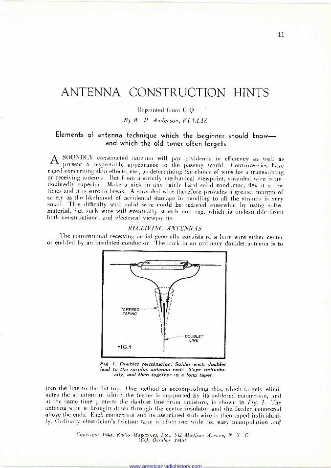
or end -fed by an insulated conductor. The trick in an ordinary doublet antenna is to
Fig. 1. Doublet termination. Solder each doublet lead to the surplus antenna ends. Tape individu-
ally, and then together in a long taper
join the line to the flat top. One method of accomplishing this, which largely elimi- nates the situation in which the feeder is supported by its soldered connection, and at the same time protects the doublet line from moisture, is shown in Fig. 1. The antenna wire is brought down through the centre insulator and the feeder connected above the ends. Each connection and its associated stub wire is then taped individual- ly. Ordinary electrician's friction tape is often too wide for easy manipulation and
Copyright 1945, Radio Magazines, Inc., 342 Madison Avenue, N. Y. C. (CQ, October 19451
www.americanradiohistory.com
12 THE RADIO ENGINEERS' DIGEST DECEMBER
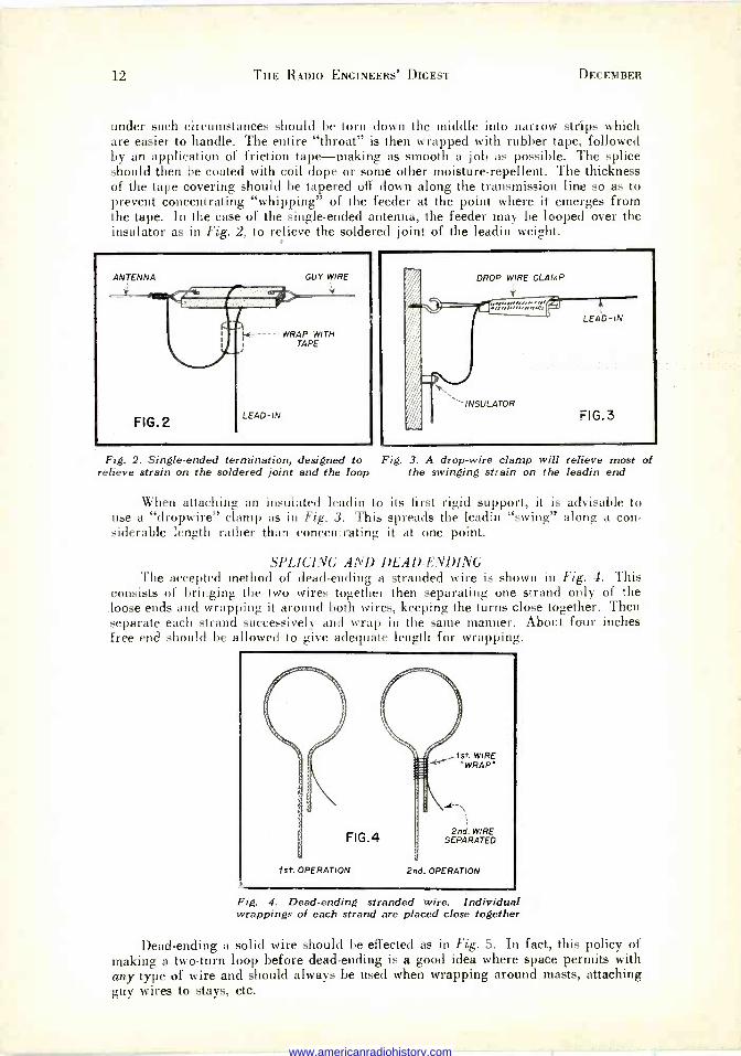
under such circumstances should be torn down the middle into narrow strips which are easier to handle. The entire "throat" is then wrapped with rubber tape, followed by an application of friction tape-making as smooth a job as possible. The splice should then be coated with coil dope or some other moisture -repellent. The thickness of the tape covering should be tapered off down along the transmission line so as to prevent concentrating "whipping" of the feeder at the point where it emerges from the tape. In the case of the single -ended antenna, the feeder may be looped over the insulator as in Fig. 2, to relieve the soldered joint of the leadin weight.
ANTENNA
FIG.2
GUY WIRE
WRAP WITH TAPE
LEAD-IN
Fig. 2. Single -ended termination, designed to Fig. 3. A drop -wire clamp will relieve most of relieve strain on the soldered joint and the loop the swinging strain on the leadin end
When attaching an insulated leadin to its first rigid support, it is advisable to use a "dropwire" clamp as in Fig. 3. This spreads the leadin "swing" along a con- siderable length rather than concentrating it at one point.
SPLICING AND DEAD -ENDING The accepted method of dead -ending a stranded wire is shown in Fig. 4. This
consists of bringing the two wires together then separating one strand only of the loose ends and wrapping it around both wires, keeping the turns close together. Then separate each strand successively and wrap in the same manner. About four inches free end should be allowed to give adequate length for wrapping.
FIG.4
1st. OPERATION
1st WIRE "WRAP'
2nd. WIRE SEPARATED
2nd. OPERATION
Fig. 4. Dead -ending stranded wire. Individual wrappings of each strand are placed close together
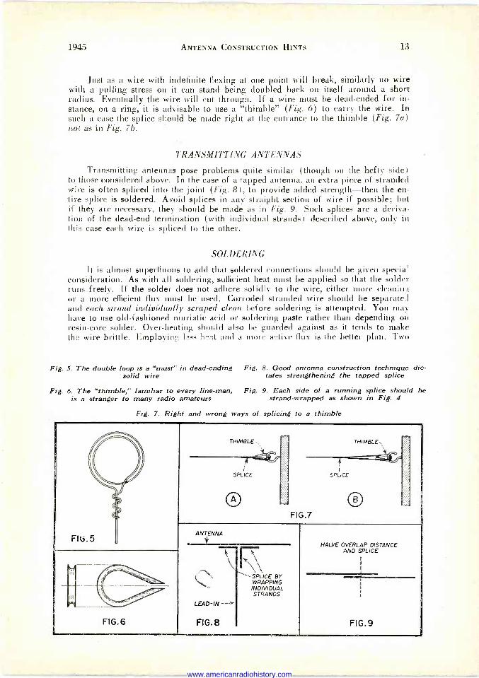
Dead -ending a solid wire should be effected as in Fig. 5. In fact, this policy of making a two -turn loop before dead -ending is a good idea where space permits with any type of wire and should always be used when wrapping around masts, attaching guy wires to stays, etc.
www.americanradiohistory.com
1945 ANTENNA CONSTRUCTION HINTS 13
Just as a wire with indefinite flexing at one point will break, similarly no wire with a pulling stress on it can stand being doubled back on itself around a short radius. Eventually the wire will cut through. If a wire must be dead -ended for in- stance, on a ring, it is advisable to use a "thimble" (Fig. 6) to carry the wire. In such a case the splice should be made right at the entrance to the thimble (Fig. 7a) not as in Fig. 7b.
TRANSMITTING ANTENNAS
Transmitting antennas pose problems quite similar (though on the hefty side) to those considered above. In the case of a tapped antenna, an extra piece of stranded wire is often spliced into the joint (Fig. 8), to provide added strength-then the en- tire splice is soldered. Avoid splices in any straight section of wire if possible; but if they are necessary, they should be made as in Fig. 9. Such splices are a deriva- tion of the dead-end termination (with individual strands) described above, only in this case each wire is spliced to the other.
SOLDERING
It is almost superfluous to add that soldered connections should be given specia' consideration. As with all soldering, sufficient heat must be applied so that the solder runs freely. If the solder does not adhere solidly to the wire, either more cleanin; or a more efficient flux must be used. Corroded stranded wire should be separates and each strand individually scraped clean before soldering is attempted. You may have to use old-fashioned muriatic acid or soldering paste rather than depending on resin -core solder. Over -heating should also be guarded against as it tends to make the wire brittle. Employing less hat and a more active flux is the better plan. Two
Fig. 5. The double loop is a "must" in dead -ending solid wire
Fig. 6. The "thimble," familiar to every line -man, is a stranger to many radio amateurs
Fig. 8. Good antenna construction technique dic- tates strengthening the tapped splice
Fig. 9. Each side of a running splice should be strand -wrapped as shown in Fig. 4
Fig. 7. Right and wrong ways of splicing to a thimble
Cl
FIt7. rJ
/
e I
THIMBLE-, -y > THIMBLE. r
,../- l
SPLICE
O
i ----(7-
SPLICE
O FIG.7
ANTENNA
Y
R\1\
HALVE OVERLAP DISTANCE AND SPLICE
LEAD-IN --->
FIG.?
'' SPLICE BY WRAPPING INDIVIDUAL STRANDS
FIG.9 FIG.6
www.americanradiohistory.com

14 THE RADIO ENGINEERS' DIGEST
100 -watt soldering irons working together generally provide sufficient heat. Blow- torches naturally have a tendency to overheat the wire. If possible, the soldering and splicing work should be done indoors where heating and cooling are more readily controlled.
ROPE SPLICING Wire or hemp ropes are often used for halyards, and splicing or dead -ending
them presents an awkward problem. For dead -ends a thimble should always be used to prevent cutting. While the technique of rope -splicing is rather difficult to put on paper, the basic ideas of one mAhod may be gleaned from Fig. 10. First of all, the ends (generally three) are fanned out to the desired length. Since these ends weave back and forth in the splice, they should be made considerably longer than the proposed splice. Anyway it's better to have some ends left over which can be cut off, than to find the splice going short on you. To be on the safe side, splices in ordinary halyards should be about 6" long at least.
THIS STRAND' WILL CROSS
THIS STRAND FIRST -- SO WILL BE
PLACED UNDER THIS STRAND ---"- FOR FIRST OPERATION. FIG.10
FAN OUT HERE, THEN INSERT ENDS OF OTHER ROPE
Fig. 11. Two ropes prepared for a running splice
Fig. 10. The first steps in a dead-end rope splice
The point of contact with the main rope where the splice is going to be started, is then fanned out by twisting backwards, and the loose ends are placed under each one of these strands with the end pointing in the opposite direction to the normal twist of the rope. In other words, the loose ends should lie at approximately 90° to the grooves in the rope-not in the grooves. Each end in turn is then threaded under the second strand which it crosses, without changing this original direction. But don't attempt to finish up one end in a single operation. Work around the rope, perform- ing one function on each end at a time, proceeding to the next in a regular sequence. If two ends come out exactly parallel, something is wrong and the splice should be undone to the point where this is no longer the case. (Better get a Boy Scout Manual or a book on ropes and splicing. Your skyhook'll stay up longer.-Ed.)
This method will be seen to bring each end strand into as great a contact as pos- sible with the rope proper, resulting in a strong, even and pliable splice. Two such operations will be necessary for a running splice. The two ends should be opened out as far as required, then tied so that the remaining solid rope will not become un- ravelled. (See Fig. 11.1
Rope with a greater number of strands may be similarly handled if care is taken to have the ends initially placed one under each strand and pointing across the strands of the rope proper as above.
www.americanradiohistory.com

15
PHOTOELECTRIC CELLS Reprinted from Service
By Willard Moody
THERE are four main types of photoelectric cells . . . photoemissive, photocon- ductive, photovoltaic and electron -multiplier. All of them respond to light; more
ductive, photovoltaic and electron -multiplier. All of them respond to light; more specifically they change light variations into electric variations.
PHOTOEMISSIVE TYPES The photoemissive cell is sometimes identified as a photocell, or phototube. They
depend upon electron emission for operation. That is, when light shines on the cell, electrons are emitted from the cathode and move to the anode or plate which is at a positive potential with respect to the cathode. This is similar to the action that takes place in the usual vacuum tube. In Fig. 1 we have a drawing of a typical photo - emissive cell. As the light intensity decreases, the emission is decreased and less, cur- rent flows in the tube. In effect, the tube is a variable resistance,- whose resistance decreases with an increase in light.
GLASS ENVELOPE
LIGHT SENSITIVE SURFACE
WIRE ANODE,
OR 'PLATE*
HEAVY NICKEL- WIRE SUPPORTS CATHODE
4 -PRONG BASE
Fig. 1. A typical photoemissive cell. Light falling on the light-sensitive surface increases the emission and consequently the current flow. This variation in current flow may be used for the control of either visual or
aural devices.
The cathode is a semi -circular cylinder -of oxidized silver, or some other suitable metal. supported by stiff wire leads of nickel. The surface of the cathode facing the plate is covered with a thin film made of caesium oxide, sodium, potassium, or lithium, or other light sensitive chemical compound. The plate is a plain nickel rod or wire placed in the center of the cylinder.
The glass envelope is soda -lime glass for many inexpensive cells, while higher priced cells may use pyrex or fused quartz, which have lower light losses and permit more ultra-violet light to pass through. Lead glass is not used, because it is a poor transmitter of light and reacts chemically in an undesirable way with the cathode materials, causing envelope discoloration.
Copyright 1945, Bryan Davis Publishing Co., Inc., 52 Vanderbilt Avenue, N. Y. C. (Service, October 19451
www.americanradiohistory.com

16 THE RADIO ENGINEERS' DIGEST DECEMBER
The plate is the smallest electrode so that it won't cast a shadow on the cathode and reduce cell efficiency. Two types of cells are used; one is a high vacuum, the other gas filled. Using gas, increased output current for a given amount of light is obtained through gas ionization. The gas also reduces the effects of space charge.
BASIC CONTROL CIRCUIT In Fig. 2 appears a typical application of a phototube, either high vacuum or
gas filled. With no light on the cell, its resistance is high and the grid potential is negative. When light shines on the cell, the resistance drops and the grid of the con- trol tube becomes less negative. The cell resistance is in series with R. the C battery,
Figs. 2 a and b. Here we have two electronic applications of the photo -tube. In the circuit in (a) light falling on the phototube in- creases the plate current, and closes the relay in the plate circuit. In (b), we have a circuit performing the reverse action. When the light on the phototube is interrupted the plate current increases
and closes the relay.
and the relay and B supply. The effect of the plate voltage on the grid becomes greater when the cell resistance is decreased. The operating conditions are usually set so that the grid is always negative, but is simply made less negative when light hits the cell. The tube plate current, which passes through the relay coil, thus in- creases. The result is a stronger magnetomotive force in the relay magnetic circuit, which attracts the armature, closing the contacts to the control circuit.
www.americanradiohistory.com
1945 PHOTOELECTRIC CELLS 17
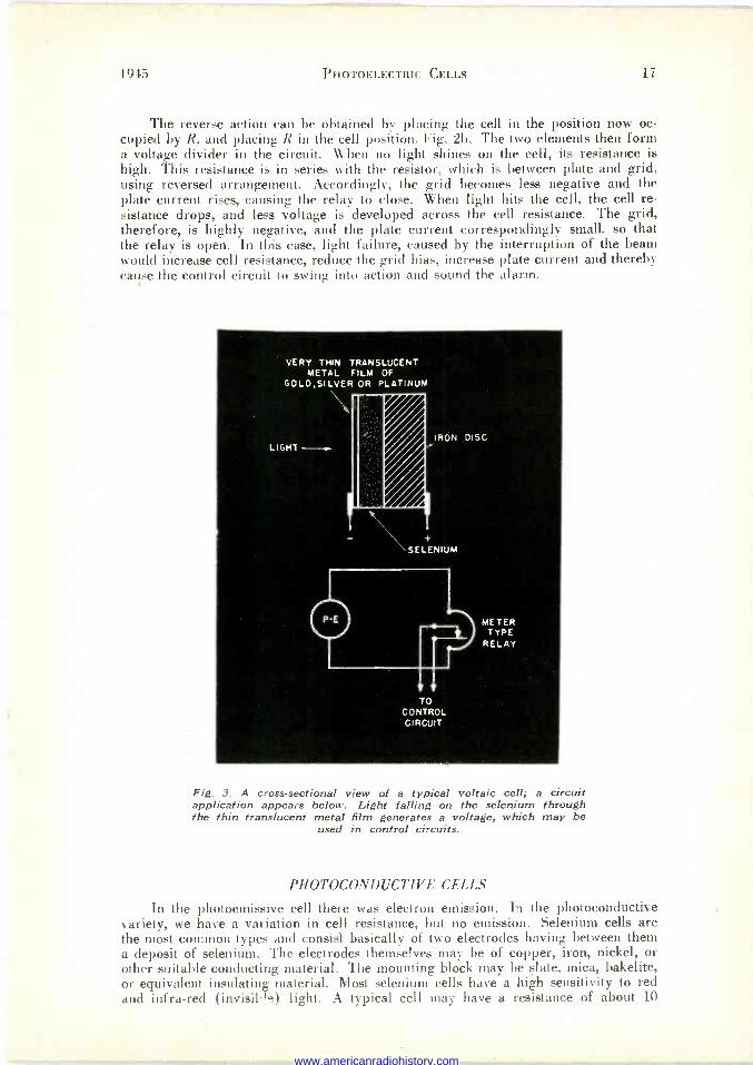
The reverse action can be obtained by placing the cell in the position now oc- cupied by R, and placing R in the cell position, Fig. 2b. The two elements then form a voltage divider in the circuit. When no light shines on the cell, its resistance is high. This resistance is in series with the resistor, which is between plate and grid. using reversed arrangement. Accordingly, the grid becomes less negative and the plate current rises, causing the relay to close. When light hits the cell, the cell re- sistance drops, and less voltage is developed across the cell resistance. The grid, therefore, is highly negative, and the plate current correspondingly small, so that the relay is open. In this case, light failure, caused by the interruption of the beam would increase cell resistance, reduce the grid bias, increase plate current and thereby cause the control circuit to swing into action and sound the alarm.
VERY THIN TRANSLUCENT METAL FILM OF
GOLO,SILVER OR PLATINUM \ a
LIGHT -11. IRON DISC
t SELENIUM
TO CONTROL CIRCUIT
METER TYPE
RELAY
Fig. 3. A cross-sectional view of a typical voltaic cell; a circuit application appears below. Light falling on the selenium through the thin translucent metal film generates a voltage, which may be
used in control circuits.
PHOTOCONDUCTIVE CELLS
In the photoemissive cell there was electron emission. In the photoconductive variety, we have a variation in cell resistance, but no emission. Selenium cells are the most common types and consist basically of two electrodes having between them a deposit of selenium. The electrodes themselves may be of copper, iron, nickel, or other suitable conducting material. The mounting block may be slate, mica, bakelite, or equivalent insulating material. Most selenium cells have a high sensitivity to red and infra -red (invisil-le) light. A typical cell may have a resistance of about 10
www.americanradiohistory.com

18 THE RADIO ENGINEERS' DIGEST DECEMBER
megohms dark and 2 megohms for an illumination of 10 foot candles. Since its action is similar to the photoemissive type it may be substituted, or used for similar application such as that shown in Fig. 2.
The cell must be kept cool and dry and not too much current can be passed through it; about 4 ma should be the maximum.
PHOTOVOLTAIC CELLS The photovoltaic cell generates a voltage, while the previous types discussed de-
veloped electron emission and changed resistance. The fundamental construction of a photovoltaic type is shown in Fig. 3. The iron disc may be only 1,/16" thick. It forms the positive terminal of the cell. The light causes electrons to be forced to the surface of the sensitized layer, to be collected by a thin translucent film which serves as the negative terminal. The loss of electrons in the metal disc makes it posi- tive. The voltage difference between the terminals is used for control of a super- sensitive meter type relay, as shown in the lower part of the figure. When light shines
Fig. 4. An electron multiplier cell. This tube has not been used too widely, but may be used more extensively in the near future. The tube uses the principle of secondary emission for amplification, each successive plate amplifying from the previous one. High plate potentials are used, since each plate is at a higher voltage level than
the previous one.
on the cell, the control voltage is developed. The fact that the cell uses selenium does not mean it is a variable resistance type. The sensitive relay may, in turn, control a
heavier relay which operates a control circuit to ring an alarm or perform some other operation. In one type, an output voltage of .15 volt for an illumination of 1 lumen is obtained. This is for a no-load condition. However, cells of this type give a linear
www.americanradiohistory.com

1945 PHOTOELECTRIC CELLS 19
response when used in low resistance circuits. Thus, the resistance in Fig. 3 might be quite low in value to give a response directly proportional to the light, as in some photelectric light -intensity meters. By putting cells in parallel, greater output current can be obtained. Photovoltaic cells are low -impedance sources, and are used with low -value resistances.
ELECTRON -MULTIPLIER PHOTOCELLS The electron -multiplier cell is not widely used at all. Essentially, this cell is a
multi -electrode photoemissive unit with the principle of secondary emission. In a typical cell we have eleven electrodes, a cathode, nine special plates called dynodes. and the regular plate. The dynodes are curved metal plates coated on one side with a mixture of chemicals. This coating is able to emit electrons when a fast moving electron strikes it. The effect is termed secondary emission.
The RCA 931-A is a typical electron -multiplier cell. The dynodes have higher potentials as the steps are increased. Differences of 100 volts between dynodes may be used. As the electrons leave the cathode and move to a dynode, secondary electrons are emitted and may go to another dynode where still other electrons due to secondary emission are released. The effect continues as the electrons move from dynode to dynode. In this way the effect of a small original electron movement is greatly am- plified. Current amplification of as much as 200,000 times may be obtained using suitable construction. Cells of this type, however, require inconveniently high, and somewhat dangerous, operating voltages. A circuit showing the connections for a typical setup appears in Fig. 4.
NEW LAMP FOR SURGEONS A new surgical lamp, expected to be of revolutionary help in operating rooms, pro- jects a cone of ultraviolet radiation through which germs cannot pass.
www.americanradiohistory.com

20
DON'T LET "INTERMITTENTS" GET YOU DOWN !
Reprinted from Radio Service Dealer By C. C. Roberts
Majority of patience -taxing intermittent receiver servicing problems can be licked with these methods.
THE most vexing claim on the serviceman's patience, resourcefulness, time and effort is the intermittent receiver. The receiver that lapses into complete or partial
inoperation, sometimes only momentarily, and often returns to normal operation at the slightest attempt to check for the trouble, proves the bane of his existence. A
high percentage of these patience -taxing service problems can be overcome by hand- ling this type of receiver trouble with the method given in this article.
For the repair of an intermittent receiver, two steps are necessary: 1. The signal failure must be made to occur; 2. The cause of the signal failure must be determined.
Both of these steps can be very troublesome. In the first place, when the re- ceiver chassis is taken from the cabinet, operating temperature changes occur which may allow the receiver to operate endlessly without the intermittent condition, being made manifest and, if the receiver chassis is taken to the shop, line voltage changes, as well as operating temperature changes may preclude its "cutting -out". In the second place, once the signal failure occurs, i.e. the receiver "cuts -out", the condition may be so critical that the mere touch of meter, signal generator, or other test equip- ment leads will produce sufficient surge -effect to restore the receiver to operation, often making it still more difficult to again cause the receiver to cut out.
HIGH OPERATING TEMPERATURE Generally, the intermittent effect (including partial signal failure, total signal
failure, and signal deterioration due to intermittent regeneration or oscillation) is
produced by a critical receiver -operating temperature in conjunction with some par- ticular value of line voltage. Thus, when a set cuts out after playing for a while, it
means that the line voltage has caused the operating temperature to rise to some critical value. Of course, this is not the only factor involved, because the conditions necessary for the receiver to cut out may not be present merely with a high line volt-
age. In other words, the line voltage may be initially high in order to raise the operating temperature, but must then drop to some lower value in order to cause
the receiver to cut out. (NOTE: The effect of very low operating temperatures will be covered at the conclusion of this article).
The effect of the operating temperature on the parts components of a receiver
is to lower the viscosity of the impregnating compound of coils and condensers and
to produce an expansion and contraction of metal surfaces. These two effects combine
to cause open circuits or short circuits within the parts themselves, or in the outside
wiring of the receiver, because a change in the viscosity of the impregnation allows
more freedom for this expansion and contraction. Thus, as an example, two metal
surfaces supposed to make electrical contact may be held together by the surrounding
Copyright 1945, Cowan Publishing Corp., 342 Madison Avenue, N. Y. C.
(Radio Service Dealer, October 1945)
www.americanradiohistory.com
DON'T LET "INTERMITTENTS" GET You DOWN! 21
impregnating compound while that compound is cool and stiff, but may be allowed to separate when the compound is heated and becomes more liquefied. Concretely, the two metal surfaces may lie:
1. An unsoldered connection between the external lead and the actual winding of an r -f, i -f or power transformer, or of a choke coil, (or any other loose connection within the part, that is underneath the impregnation) . (See Fig. II) .
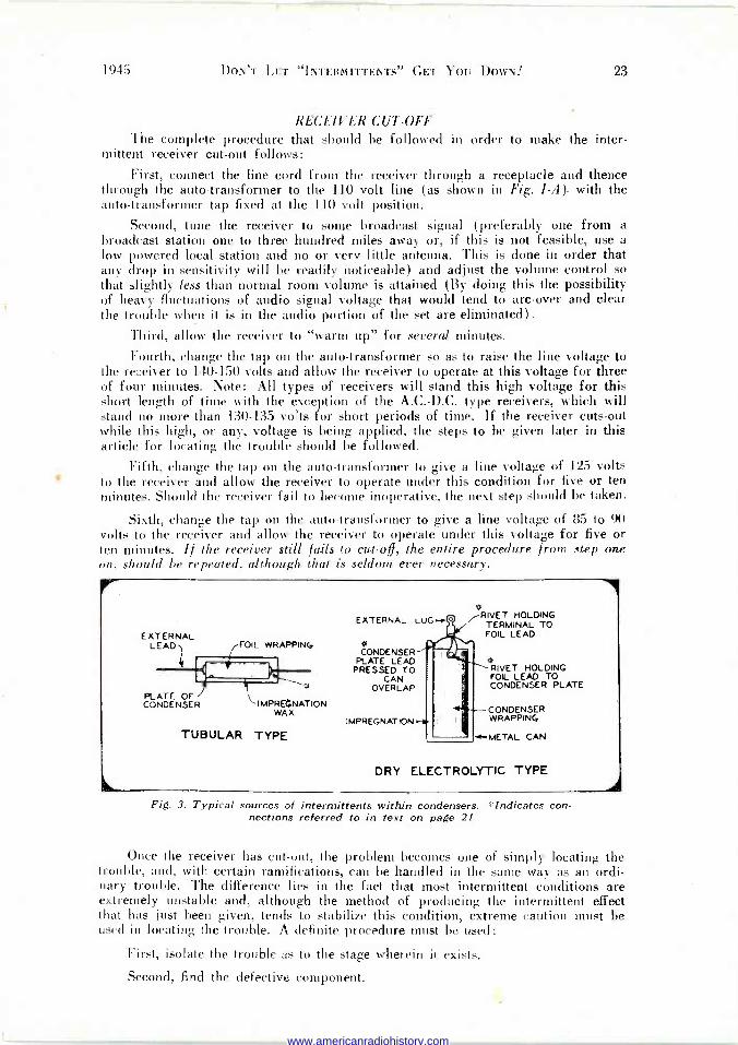
2. A loosely riveted or pressed connection between the plate or foil of a con- denser and the external contact. (See Fig. III).
3. A movable element within a tube.
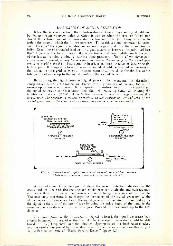
4. Faulty resistors. (See Fig. IV).
(NoTE: Ordinary loose or unsoldered connections in tubes, wiring or any other component part are disregarded in this discussion because the simple process of jarring or tapping the receiver is the best method both of making such troubles manifest themselves, and, of locating them.)
CONNECT TO AC LINE
cou 150V.
.AUTO TRANSFORMER
RECEIVER LINE CORD y
RECEPTACLE
--SELECTOR SWITCH (BATTERY CLIP MAY BE USED IN PLACE OF SWITCH)
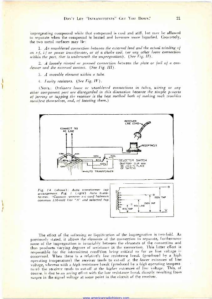
Fig. lA (above): Auto transformer tap arrangement. Fig. I (right) Auto trans- former. *Connect receiver a -c cord between common 110 -volt line "A" and selected tap
150V TAP
130v TAP * 110V. LINE
85V. TAP
The effect of the softening or liquification of the impregnation is two -fold. As previously stated, it allows the elements of the connection to separate, furthermore some of the impregnation is invariably between the elements of the connection and thus produces varying degrees of resistance in the connection. This latter effect is
responsible for the intermittent condition being critical so far as line voltage is
concerned. When there is a relatively low resistance break (produced by a high operating temperature) the receiver tends to cut-off at the lower extremes of line voltage, whereas with a high resistance break (produced by a high operating tempera- ture) the receiver tends to cut-off at the higher extremes of line voltage. This, of course, is due to an arcing effect with the low resistance break directly resulting from surges in the signal voltage at some point in the circuit of the receiver.
www.americanradiohistory.com

22 THE RADIO ENGINEERS' DIGEST DECEMBER
o I
UNSOLDERED -- CONNECTION BETWEEN WINDING AND LEAD L_
The intermittents traceable to non -impregnated parts, (i.e. tubes and resistors; excepting those cases that obviously are loose connections as evidenced by jarring or bumping the parts themselves or the receiver chassis) are affected by operating temperatures and line voltages in the same manner as that previously described for the impregnated parts, although they are not nearly as critical or hard to find be- cause of the freedom for expansion present due to the absence of impregnation.
I WINDING EXTERNAL I 1 'LEADS
7 RIVET
LUG t -CONDENSER -LOOSE RIVETING
BETWEEN PLATES TRIMMER, OF CONDENSER
AND EXTERNAL
OCONNECTION I. F. TRANSFORMER
UNSOLDERED - CONNECTION
BETWEEN COIL WIRE d
LUG
TERMINAL LUGS
O
.-IMPREGNATION
WINDING
--COIL FORM
R.F TRANSFORMER (wAx DIPPED)
Fig. 2. Typical sources of intermittents within transformer assemblies and coils. *Indicates connections referred to in text (page 21). (Note: second-
ary winding omitted for simplicity).
THE PROCEDURE 1. From the foregoing general analysis, it can be seen that the first condition
to create, in order to cause the receiver to cut out, is the high operating temperature. Furthermore, by making this temperature as high as safety will permit, maximum expansion of the metal surfaces will be attained. In order to have the receiver chassis in an accessible position, it should be removed from the cabinet and placed on the bench so that it stands on end. This gives ready access to both the tubes and the components located underneath the chassis. A broadcast station signal should be tuned in and the volume control of the set adjusted to slightly less than normal room volume. A heavy cardboard box should then be placed over the receiver chassis so as to completely cover it, leaving the loud speaker on the outside. This will produce a rising operating temperature by preventing any air circulation and thus any cooling effects.
2. The second condition to create is the critical line voltage necessary to break down the offending part or recreate the signal and supply voltage conditions neces- sary to produce the intermittent operation and cause the receiver to cut-off. To obtain the necessary line voltage an auto -transformer, (Fig. I), with voltage taps as shown, is needed. Such a transformer can be constructed from an old automobile radio power transformer or purchased ready made from "Jensen", "Kenyon" or "Thord- arson".
Note that a high voltage tap of 150 volts is provided. This tap is advantageous for two reasons: first, it can be used to cause a rapid rise to an abnormally high op- erating temperature especially when used in conjunction with the cardboard box; second, it can be used to cause abnormally high signal and supply voltages (plate voltages, filament voltages, etc.) thereby accentuating any possible arcing on break- down in the condensers, resistors, or tubes as well as forcing the maximum expansion of those impregnated surfaces described as being the causes of intermittent conditions. The remaining taps are provided in order to have both low and intermediate line voltages available as shall be later shown.
www.americanradiohistory.com
1945 DON'T LET "INTERMITTENTS" GET You DOWN 23
RECEIVER CUT-OFF The complete procedure that should be followed in order to make the inter-
mittent receiver cut-out follows:
First, connect the line cord from the receiver through a receptacle and thence through the auto -transformer to the 110 volt line (as shown in Fig. I -A). with the auto -transformer tap fixed at the 110 volt position.
Second, tune the receiver to some broadcast signal (preferably one from a broadcast station one to three hundred miles away or, if this is not feasible, use a low powered local station and no or very little antenna. This is done in order that any drop in sensitivity will be readily noticeable) and adjust the volume control so that slightly less than normal room volume is attained (By doing this the possibility of heavy fluctuations of audio signal voltage that would tend to arc -over and clear the trouble when it is in the audio portion of the set are eliminated).
Third. allow the receiver to "warm up" for several minutes.
Fourth, change the tap on the auto -transformer so as to raise the line voltage to the receiver to 140-150 volts and allow the receiver to operate at this voltage for three of four minutes. Note: All types of receivers will stand this high voltage for this short length of time with the exception of the A.C.-D.C. type receivers, which will stand no more than 130-135 volts for short periods of time. If the receiver cuts -out while this high, or any, voltage is being applied, the steps to be given later in this article for locating the trouble should be followed.
Fifth, change the tap on the auto -transformer to give a line voltage of 125 volts to the receiver and allow the receiver to operate under this condition for five or ten minutes. Should the receiver fail to become inoperative, the next step should be taken.
Sixth, change the tap on the auto -transformer to give a line voltage of 85 to 90 volts to the receiver and allow the receiver to operate under this voltage for five or en minutes. If the receiver still fails to cut-off, the entire procedure from, step one
on. should be repeated. although that is seldom ever necessary.
EXTERNAL LEAD) ¡FOIL WRAPPING
PLATE OF / CONDENSER -IMPREGNATION
WAX
TUBULAR TYPE
EXTERNAL LUG-,
CONDENSER PLATE LEAD
PRESSED TO CAN
OVERLAP
IMPREGNATION
a /RIVET HOLDING
TERMINAL TO FOIL LEAD
RIVET HOLDING FOL LEAD TO CONDENSER PLATE
CONDENSER WRAPPING
METAL CAN
DRY ELECTROLYTIC TYPE A
Fig. 3. Typical sources of intermittents within condensers. *Indicates con- nections referred to in text on page 21
Once the receiver has cut-out, the problem becomes one of simply locating the trouble, and, with certain ramifications, can be handled in the same way as an ordi- nary trouble. The difference lies in the fact that most intermittent conditions are extremely unstable and, although the method of producing the intermittent effect that has just been given, tends to stabilize this condition, extreme caution must be used in locating the trouble. A definite procedure must be used:
First, isolate the trouble as to the stage wherein it exists.
Second, find the defective component.
www.americanradiohistory.com
24 THE RADIO ENGINEERS' DIGEST DECEMBER
APPLICATION OF SIGNAL GENERATOR When the receiver cuts -off, the auto -transformer line voltage setting should not
be changed from whatever value at which it was set when the receiver failed, nor should the volume control or tuning dial be touched. The first thing to do is to isolate the stage in which the failure occurred. To do this a signal generator is neces- sary. First, set the signal generator for an audio signal and turn the attenuator on fully. Grasp the ungrounded lead of the signal generator between the palm and last three fingers of the hand. Extend the index finger and very lightly touch the grid of the last audio tube, gradually exerting more pressure. (NOTE: If the signal gen- erator is a -c operated, it may be necessary to reverse the a -c plug of the signal gen- erator to avoid a shock) . If' no signal is heard, steps must be taken to locate the de- fective part. If a signal is heard, the audio signal should be applied to the next to the last audio tube grid in exactly the same manner as was done for the last audio tube grid and so on up to the signal diode of the second detector.
By applying the signal from the signal generator in the manner just described, sharp signal surges are avoided and therefore the possibility of causing the set to resume operation is minimized. It is important, therefore, to apply- the signal from the signal generator in this manner, throughout the entire operation of isolating the trouble as to stage. (NoTE: As a further caution to minimize signal surges that might cause the receiver to resume operation. do not connect the ground lead of the signal generator to the chassis at any time once the receiver has cut-out.)
3> RIVETED CONNECTION BETWEEN
TERMINAL AND WIRE CARBON
ELEMENT
"METAL ENDS MOLDED TO RESISTANCE
ELEMENT -
0 Wp2EWOUND ' RESISTOR COMPOSITION RESISTOR
(wAx DIPPED) (wAx DIPPED)
FIBRE PAPER COVERING FOR RESISTANCE
WIRE\
METAL SHEATH --- '
O CANDOHM TYPE RESISTOR
BODY
TERMINAL PRESSED ONTO RESISTANCE WIRE
1
Fig. 4. Illustration of typical sources of intermittents within resistors. *Indicates connections referred to in text (page 21).
A normal signal from the signal diode of the second detector indicates that the audio and rectifier and also the speaker of the receiver is alright and consequently eliminates those portions of the receiver circuit as being the source of the trouble. The next step, therefore, is to change the frequency of the signal generator to the i -f frequency of the receiver. Leave the signal generator attenuator fully on and apply the signal to the grid of the last i -f tube by using the index finger of the hand in the same way as was done with the audio stages. Proceed in this manner up to the first detector.
If at some point, in the i -f system, no signal is heard, the signal generator lead should be moved to the grid of the first r -f tube (the signal generator should be still tuned to the i -f frequency) and the trimmer adjustments of the dead stage checked and the results interpreted by the method given in the previous article on this subject in the September issue of "Radio Service Dealer" (page 121.
www.americanradiohistory.com
1945 DON'T LET "INTERMITTENTS" GET You DowN! 25
If normal i -f signal is present from the grid of the first detector on, the i -f system of the receiver is operating. The signal generator frequency should be changed to coincide with the broadcast frequency to which the receiver is tuned. If no signal is heard, the components of the oscillator stage of the receiver should be checked with an ohmmeter. If a signal is heard, the signal generator lead should be applied to the grids of the r -f tubes, in succession, and the results interpreted as outlined in the previous article.
CHECK WITH OHMMETER Once the faulty stage has been identified, the problem becomes one of locating
the defective part. Inasmuch as the possibility of shocking the receiver back in to operation still remains, all checking for the defective part should be done with an ohmmeter. By carefully removing the rectifier tube, checks with the ohmmeter can be made. Removing the rectifier tube, instead of turning the power off the set, tends to minimize any surge effect and this should be done before attempting to change tubes or make any continuity checks. Checking with a voltmeter or substituting capacitors or resistors across suspected defective parts should be avoided whenever possible as this tends to produce a surge which is likely to restore the receiver to operation.
Before making any further checks for the cause of failure in any stage, the tube should be eliminated as a possible cause of the intermittent condition. The only way to be absolutely sure that the tube is not the cause is to substitute a new one for the one in use. (NoTE: Change the tube in the dead stage after first removing the rectifier tube as previously stated.)
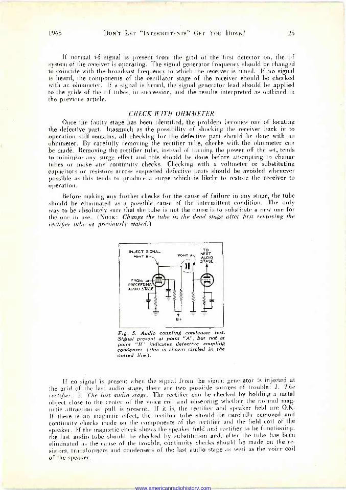
INJECT SIGNAL ^PINT e--,
FROM PRECEE DING AUDIO STAGE
TO POINT A\ NEXT
AUDIO .) STAGE
8+
Fig. 5. Audio coupling condenser test. Signal present at point "A", but not at point "B" indicates defective coupling condenser (this is shown circled in the dotted line).
If no signal is present when the signal from the signal generator is injected at the grid of the last audio stage, there are two possible sources of trouble: 1. The rectifier. 2. The last audio stage. The rectifier can be checked by holding a metal object close to the center of the voice coil and observing whether the normal mag- netic attraction or pull is present. If it is, the rectifier and speaker field are O.K. If there is no magnetic effect, the rectifier tube should be carefully removed and continuity checks made on the components of the rectifier and the field coil of the speaker. If the magnetic check shows the speaker field and rectifier to be functioning, the last audio tube should be checked by substitution and, after the tube has been eliminated as the cause of the trouble, continuity checks should be made on the re-
sistors, transformers and condensers of the last audio stage as well as the voice coil
of the speaker.
www.americanradiohistory.com

26 THE RADIO ENGINEERS' DIGEST
If the faulty audio stage is any one but the last stage in the audio system, the possible sources of trouble would be narrowed dowp to the components of the faulty stage only. The components of the faulty audio stage should be checked by the con- tinuity method. The coupling condensers (which are very often the source of inter- mittent troubles in the audio system) cannot be checked with an ohmmeter but may be checked with the signal generator, (see Fig. V) , using the index finger to avoid signal surges as previously described.
If the faulty stage is in the i -f, r -f or oscillator portions of the receiver, the de- fective part can be identified by observation of the trimmer reactions and by con- tinuity checks. As before stated the rectifier tube should always be removed before using the ohmmeter.
LOW OPERATING TEMPERATURE Oftentimes the characteristics of the component -source of the intermittent are
such that contraction of the metal surfaces is essential for non -operation. In such cases low operating temperatures are involved, hence the receiver either fails to start operating or fails after operating a very short time. The procedure in such cases is the very same as for the opposite operating temperature effect, excepting that an artificially low temperature must be created. There are two ways of cooling the chassis and accomplishing this:
One is to place the chassis out-of-doors for a time. (Obviously this can be effective only when the outside temperature is below 40° F, approximately).
The other way is to place the chassis in an empty electric refrigerator, or place it beneath a cardboard box together with a couple of pounds of dry ice, for a time.
Whichever method is used, the receiver should be turned off before being allowed to cool for fifteen or twenty minutes and then removed, plugged in, and checked. As a general rule, in such cases, the auto -transformer should be set at the extreme low line voltage first. If the receiver starts immediately, after being cooled, it should be operated only one or two minutes at a time on each of the voltages supplied by the auto -transformer beginning with the lowest. If the receiver fails to cut-off, or oper- ates instantly on all voltages, it should be re -cooled and the entire procedure repeated.
In some very obstinate cases of intermittents, cooling the chassis to an ab- normally low temperature and then heating it to an abnormally high temperature is the only way to invoke the signal failure and, in other instances, the only way to make the signal failure stable enough to handle it with any procedure. Repeating successively the two methods of obtaining the extremes of operating temperatures will have the effect of working the faulty connection, within a component, loose. The receiver should first be cooled and then heated, as previously described, as many times as is necessary to effect a signal failure stable enough to be handled.
If the method of handling intermittents, that has just been given, seems like a great deal of bother, it should be remembered that the positive results obtained eliminate the guess work common to the hit-or-miss methods, and, as a result the likelihood of repeat -calls to the customer's home, as well as customer dissatisfaction. is eliminated.
www.americanradiohistory.com
97
RADIO AHEAD ON THE HANDIE - TALKIE
Reprinted from Domestic Commerce By Robert C. Smith
Transportation Unit, Bureau of Foreign and Domestic Commerce
IF YOU are a United States citizen, you may be eligible to obtain a license to op-
erate a limited -range portable radio transmitter for your private use. This is one of the new services which will be available to the public in the next few months as a result of the development of portable short-range radio communications equipment of the walkie-talkie and handie-talkie type for use by the armed forces.
In general style, the handie-talkie set resembles an oversized telephone hand set. A combination transmitter and receiver, together with the batteries which supply the power, is contained in a (a>c which may be held in the hand. An antenna of the telescoping type extends from one end.
OPERATION SIMPLE The instrument is simple to operate. To talk, the user presses a button and
speaks into the transmitter. When he is ready to receive a message, he releases the button and listens. Since the user cannot transmit and receive at the same instant, no one can interrupt him until he releases the button and is ready to receive.
In order to establish communications certain arrangements must be made in advance. There must be two or more persons equipped with similar two-way sets within signal range of each other-a distance of from 2 to 5 miles or less. An agree- ment must be made between the correspondents on the frequency to be used. Some arrangement also must he made to notify the person called that there is a message for him.
TIME SCHEDULE HELPFUL In some cases this arrangement may consist of a time schedule that has been
agreed on. Or the transceiver (combination transmitter and receiver) may be equipped with either an aural or a visual signaling device, such as a buzzer or a light flashing on. While the signaling device will increase slightly the cost of opera- tion by making it necessary to have a part of the circuit in operation at all times, it is a convenience to the user by permitting calls to be made at other times than pre- viously arranged.
To illustrate use of the equipment, suppose that A wishes to communicate with B. The procedure is similar to using a party telephone line. A turns on his receiver and tunes it to the frequency agreed on. He listens to make sure that no one else is using the channel or line. If the channel is free, A turns on his transmitter, which rings a bell or flashes a light on B's receiver. A code designation of a series of rings or flashes could be used to distinguish B's receiver from other receivers tuned in on that frequency. When B notices the signal indicating a call for him, he turns on his transmitter and acknowledges the call, indicating that he is ready to receive the message. From this point on A and B alternate at transmitting and receiving until their conversation is completed. The channel is then available to another pair of users.
(Domestic Commerce, November 1945)
www.americanradiohistory.com

28 THE RADIO ENGINEERS' DIGEST DECEMBER
A PERSONAL SERVICE The citizens' radio communications service should not be confused with the
common carrier mobile radio service which may be established. The citizens' radio is purely a free, personal communications service which has largely been developed out of wartime research and experimentation. During the past few Years, the useful portion of the radio spectrum has been shifted rapidly upwards: As a result of this upward shift, the Federal Coininunications Commission has been able to allocate the band from 460 to 470 megacycles for this new service.
An understanding of the characteristics of radio waves transmitted in the high frequency ranges is necessary to understand both the limitations and the possibilities of the citizens' radio service.
Radio waves at high frequencies follow a line -of -sight path. This characteristic limits the range of the transmitter to a distance of from 2 to 5 miles, depending on the power of the transmitter and the terrain. The presence of hills. large buildings, and other obstructions tend to lessen the range of the transmitter.
RANGE IS LIMITED On the other hand, it is the limited range of the transmitters ill this service that
will make it possible for so many individuals to own and operate handie-talkies. In contrast with the standard broadcast stations which cover such wide areas that it is possible to assign the same frequency to only a few widely separated stations, the same frequency may be used simultaneously by thousands of handie-talkies through- out the country. Even within any given area, the 10,000 -kilocycle wave band allocated the service will make possible the simultaneous use of many sets.
If the equipment utilizes a channel of 150 kilocycles, some 66 channels would be available for simultaneous operation. However, most of the sets will be used only intermittently, some only a few times a day. Thus, aside from the possible ex- ception of difficulty in large urban areas, little interference is anticipated because of too many sets being in operation. In some cases it may be necessary for the user to wait for a clear channel in much the same way he must wait while a telephone line is busy.
NOT A NOVELTY Undoubtedly there are many who regard personal radio communication as a
novel means of transmitting the voice without benefit of wires or other physical con- nection. The citizens' radio communications service must be more than just a novelty if it is to justify its space in the radio spectrum. It must fulfill a real need in the economy of the country.
Those who are interested in the citizens' radio see it as a possible means of furnishing low-cost mobile communication service to large numbers of users for adaption to their own particular needs. The Federal Communications Commission has proposed to issue as few restrictive regulations as possible to encourage the widest possible use of the service.
USES ARE VARIED Some of the uses to which the service lends itself are obvious. Others are open
to the ingenuity of the users in response to special needs. At any rate three general classes of uses for the service present themselves-emergency use, protection use. and business use.
Wire communications in times of disaster are subject to disruption by fire, flood, wind, earthquake, or other ravages of nature. Radio has frequently been used by officials directing rescue work after such disasters. If even a small percentage of the victims of such disasters had two-way radios in their possession, rescue work might be greatly facilitated, not to mention the additional comfort that communica- tion would bring to the minds of the victims.
www.americanradiohistory.com

1945 RADIO AHEAD ON THE HANDIE TALKIE 29'
URBAN AND RURAL FACTORS Large cities have special wave bands assigned for the use of their police and
fire departments. Small urban and rural areas usually do not have the need for an exclusive wave band nor do they have the money to invest in elaborate radio equipment. Yet by using the citizens' radio service they may enjoy all the benefits of two-way radio with only a portion of the financial outlay a more elaborate radio system would take.
The greatest use of the citizens' radio, however, is expected to be in the ordinary business world where men and women move about in their daily activities. Here the potential demand for two-way radio may ultimately be measured in terms of millions of users rather than hundreds or thousands.
DISTRIBUTION FIELD AID The distribution field alone suggests uses for thousands of sets. As of August
31, 1944, 678,085 motor trucks certified by ODT, were engaged in retail distribution with an additional 367,143 trucks engaged in wholesale distribution. These trucks were operated by department stores, dairies, laundries, newspapers, drug stores, garages, and others. The sizes of these establishments ranged from those operating whole fleets of delivery trucks down to the enterprise operating one truck. All such operators will be eligible to use the citizens' radio communication service, but each will have to determine for himself on the basis of his own particular needs what two-way radio may do to promote his business.
The use of two-way radio can result in a direct saving to the business concern and better service to the customer. Direct savings may be made through eliminating travel consumed by drivers in seeking further instructions and through minimizing the dead mileage of empty vehicles. Two-way radio permits immediate changes in pick-up and delivery schedules while the truck is on the run. For example, a customer phones in to a laundry office to have his laundry picked up. The laundry office radios the message to the truck already enroute on the day's delivery schedule. The driver can make the necessary change in his schedule to include immediate service to the customer.
MAY NEED BOOSTERS The range of the citizens' radio may be insufficient to cover the delivery area of
large metropolitan centers. This handicap may be overcome by use of an automatic relay or booster station which will pick up the signals, amplify them, and relay them to a more distant receiver. A department store, for example, might install four or five relay stations at vantage points in various sections of the city.
A radio beam directed at these relay stations from a central transmitter would be picked up and relayed to receivers installed in trucks in outlying areas. Since the relay transmitters would probably be located on roofs of buildings or towers, the line -of -sight range would be greatly increased over transmitters operating at ground level.
LONGER SENDING RANGE The favorable location of relay transmitters, plus the added power possible for
fixed transmitters, should give adequate coverage over any urban area. Delivery trucks, equipped with lower powered transmitters and operating at ground levels, would be able to receive messages at a greater distance than they could transmit. Thus, one-way communication only would be available to the trucks in outlying areas. But since most of the traffic would consist of messages from the central transmitter to the trucks, one-way communication probably would not seriously lessen the value of the mobile radio service.
The installation of relay stations would increase considerably the investment in equipment. This added cost factor will limit the use of relay stations to large organizations operating a number of receivers over a wide area, or in some cases to a cooperative group formed by smaller users.
www.americanradiohistory.com

- 30 THE RADIO ENGINEERS' DIGEST DECEMBER
AUTO OWNERS' USE Automobile owners comprise another large group of potential users of the
citizens' radio service. Before the war some 27,700,000 private automobiles were in operation in the United States. If actual practice indicates that the service contributes to the convenience, pleasure, and safety of motoring, many motorists will desire to use two-way radios in their automobiles.
Motorists traveling in groups of two or more cars each equipped with two-way radio would have the convenience of talking between cars, arranging routes to be taken and other details incidental to traveling. As highways become more crowded, it will grow more difficult for parties traveling in groups to remain together.
Safety on the highway will be of increasing concern as more cars appear. The highway accident rate was approaching alarming proportions before the war. While improved highways and better automobiles will point toward greater safety, mobile communication may assist materially.
POLICE AIDS AND COOPERATION If even a small percentage of automobile owners decide to use two-way radios
in their cars, it may be practical to have highway patrol cars carry a radio operating on the citizens' radio band as an auxiliary to the regular police radio. Motorists could communicate with patrolmen to ask for traffic directions and road conditions. Patrolmen could communicate with motorists in case of traffic tie-ups. Not only could directions be given more explicitly by voice than by signaling, but cars far back in line could be informed of the traffic difficulty. Traffic signs at congested spots might be used to request motorists to tune their radios to a specified frequency for traffic directions.
Some attention has been devoted to setting up first -aid stations along the high- ways. A system of such stations, set up at regular intervals along heavily traveled highways and equipped with radio tuned to the citizens' wave bands, might prove to be extremely effective in providing immediate medical attention in case of emer- gency. If the service should prove effective, it might even be found desirable to reserve a special channel for emergency calls. Should a motorist's own radio become damaged beyond use in an accident, a passing motorist could use his radio to sum- mon aid.
HIRING A ROOM Garages, filling stations, and tourist homes offering services to motorists may
find the citizens' radio communications service a means of obtaining additional busi- ness. Garages and tourist homes could advertise on road maps and roadside signs the fact that they were equipped with two-way radio. Toward the end of the day's journey the tourist could consult his road map, note the tourist homes equipped with radio, their listening frequency, and then, while still 4 or 5 miles away, proceed to inquire about reservations for the night. If no rooms were available, he would know without wasting time in stopping. If his car should break down he could radio a mechanic from the nearest garage.
There will be many who will recognize in the citizens' radio service a means of communication adaptable to their own particular needs. Likely uses are suggested briefly here to indicate the wide range of possibilities for the service.
A DOCTOR IN THE VICINITY? Physicians and public servants may leave their telephones and still be within
range of emergency call. Two-way radio may be used in communicating to and from trucks, tractors, and other mobile units operating around large industrial plants and construction projects. Operators of large farms and ranches may use radio to communicate with hired help working on various parts of the farm. Or the house- wife may simply pick up a microphone to call her husband to dinner. Newspaper
www.americanradiohistory.com
1945 RADIO AHEAD ON THE HANDIE TALKIE 31
reporters may report to their papers by radio on a happening as it is taking place. Sportsmen and explorers can use the service to maintain contact with camps and lessen the hazards of hunting, fishing, boating, and mountain climbing.
Although the primary objective of the citizens' radio is to provide a low-cost personal radio communication service to large numbers of users, the resulting op- portunities for business and employment appear to be substantial at the manufactur- ing, sales, and servicing levels.
A NEW MARKET POTENTIAL The ending of the war left the electronics industry with greatly expanded pro-
duction facilities. Although there is at present an accumulated demand for millions of standard broadcast receiving sets, continued high production and employment levels will depend in part on extending radio to new fields of operation. Since the citizens' radio service is not restricted to any particular group of users, the potential demand for such equipment may be very high.
The small manufacturer as well as the large should find an opportunity in the construction of transceivers suitable for this service. Statements already appearing in the press indicate that manufacturers may be able to produce sets to retail at less than $50. This suggests low unit manufacturing costs well within the reach of the small manufacturer.
Although some precedent for design has been set in the familiar handie-talkies used in the armed services, civilian usage may make modifications desirable. For ex- ample, those who expect to use sets in delivery trucks and automobiles may want them designed for installation in the dash. Those desiring portable sets will want them to be as light and as compact as possible. Some users may even want pocket-size. sets. A facsimile unit which leaves a written record of the message would he convenient for the set user who is away from his transceiver when a call comes in.
COST OF OPERATION Economy of operation will be an important consideration. Direct operating costs
are usually limited to the cost of supplying power. Dry batteries, readily replaceable after their service life has expired, have usually been the most convenient source of power for portable radio operation. With intermittent operation dry batteries should be able to operate a set for several months before replacement. Small wet batteries, too, have been developed for portable radio operation. Since these may be recharged as needed, their service life is longer than that of dry batteries. A third alternative power source is the power line or combination battery and power -line operation. The user could conserve his batteries by plugging in on a power outlet whenever convenient. At other times the set is operated by batteries. If a set is to be used continuously in an automobile or delivery truck, the car battery would be the most convenient and economical power source.
Salesmen will have the responsibility not only of selling the two-way sets but also of adequately explaining their operation. Much of the success of this new radio service will depend on how well individual owners understand their equipment and its practical application. Aside from range and other limitations, communications can be intercepted or listened in on as in the case of a telephone party line.
LIMITED RANGE The set owner should understand that the citizens' radio has a limited range of
operation and that it cannot be expected to replace the telephone. In crowded urban areas the number of channels allocated may be insufficient for unlimited operation, and salesmen should give full instructions on how to make the best use of the chan- nels available.
Because of the interference that a faulty transmitter may cause, service standards should be high. Repairs to transmitters will require men well trained in high -fre- quency radio circuits. There will be many veterans returning from the armed ser-
www.americanradiohistory.com

32 THE RADIO ENGINEERS' DIGEST
vices with practical training in radio and radar work who will want to carry their acquired skills into civilian lfe.
WIDE SPREAD USE DESIRED The final success of the citizens' radio is contingent upon widespread usage by
those in need of a low-cost, flexible, and mobile communications service. The Federal Communications Commission in establishing the service has envisaged the broadest possible uses for it. The Commission has allocated a wave band containing a suf- ficient number of channels for a fair trial. Unless it is shown that these channels will be used to good advantage in the citizens' radio service. undoubtedly they may be assigned to other needs.
Few restrictions are expected to be placed on operation of the citizens' radio. To operate a transmitter one must have a license from the Federal Communications Commission. To be eligible for a license the applicant must be a United States citizen. He will not be required to have a technical knowledge of radio operation, but should be familiar with the regulations applying to this service. No charge may be made for transmitting or receiving messages and the service will not be available for broadcasting. Now that the war is over and security rules permit the use of pri- vately owned stations, there is a possibility that the Federal Communications Com- mission will be ready to issue licenses by the end of this year.
INITIAL PROBLEMS The manufacturer will have the responsibility of developing low-cost sets which
will be within the price range of the many potential users. If people with moderate incomes are given an opportunity to derive benefits from the citizens' radio, the result will be more opportunities for sales and more jobs in the radio industry.
The most difficult task may be to get the first sets in the hands of representative users. The value of two-way radio will increase in proportion to the number of per- sons with whom the owner of a set can talk. In many cases an individual or firm will find it necessary to buy two or more sets. If garages, filling stations, and tourist homes have sets installed, motorists will be encouraged to use sets in their cars. Thus the demand for two-way radio should grow more rapidly as more people become acquainted with the service.
It is anticipated that the 60 or 70 channels available should be sufficient for small urban and rural areas. In larger urban areas, assuming widespread usage of the service, the channels may become overcrowded. Such a development may neces- sitate some planning for the orderly use of frequencies.
The Federal Communications Commission proposes to issue few limiting regu- lations and that agency has indicated its willingness to cooperate with voluntary groups to work out satisfactory arrangements for using the frequencies available. Since the average set owner would need to use the service only intermittently, a voluntary sharing of use on a time basis might be advocated. There seems to be no reason why the best possible use cannot be made of the service for the mutual benefit of all concerned if individual owners cooperate.
www.americanradiohistory.com

N. Y. NAVY YARD'S QUIET ROOM Reprinted from Communications
By William M. Rees Acoustical Specialist,
Owens-Corning Fiberglas Corporation
THE New York Navy Yard in Brooklyn, features one of the quietest spaces in the world, a specially designed silent 16' x 26' x 12' high room in which ship micro-
phones, telephones, loudspeakers and other communications devices can be calibrated for level and fidelity.
Designed for as low as 1 cps and for a noise level of 24 db, the usual range of frequencies for which the room is used is between 200 and 20,000 cps. The noise level is less than 20 db, and at most frequencies is in the order of 15 db; 4 cps is approximately 16 cycles below the lower limit of audible sound, while a noise level of 15 db just above the threshold of audibility.
o _ r
i`hs.,L
.1-- 24' - FIBERGLAS
PANEL
INTERIOR OF
QUIET ROOM
STEEL FRAMEWORK
FIBERGLAS PNELS C'+
rilIiuifii FIBERGLAS AND FIBERBOARD FLOOR
10' THICK
FREE SPACE . WIDE
0ti¡ i-+FIBËRGLAS ;6 THICKee,h*
I%1/IIIIIIIINIuhIIIll ONCRETE PANEL ` T ICKIIIIIIIIfIIIIIIß,
////I/////u///////I/N CONCRETE FLOOR OF BUILDING .. .6' THICK Illlll/l'Illllllllllil
CC
mg m J O KU
Fig. 1. Cross-sectional view of construction of the quiet room in the N. Y. Navy Yard in Brooklyn.
Copyright 1945, Bryan Davis Publishing Co., Inc., 52 Vanderbilt Avenue, N. Y. C. (Communications, October 1945)
www.americanradiohistory.com
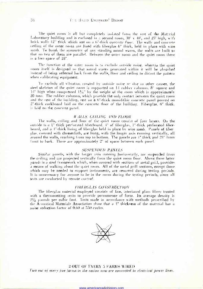
34 u o ENGINEERS' DIGEST
The quiet room is all but completely isolated from the rest of the Material Laboratory building and is enclosed in a second room, 30' x 40', and 25' high, with brick walls 12" thick which rest on a 6" -thick concrete floor. The walls and concrete ceiling of the outer room are lined with fiberglas 6" thick, held in place with wire mesh. To break the symmetry of any standing sound waves, the walls are built so that no two of them are parallel. Between the outer room and the quiet room there is a free space of 18".
The function of the outer room is to exclude outside noise, whereas the quiet room itself is designed so that sound waves generated within it will be absorbed instead of being reflected back from the walls, floor and ceiling to distort the pattern when calibrating equipment.
To exclude all vibration created by outside noise or due to other causes, the steel skeleton of the quiet room is supported on 11 rubber columns, 8" square and 14" high when compressed 11/2" by the weight of the room which is approximately 20 tons. The rubber columns, which provide the only contact between the quiet room and the rest of the building, rest on a 6" -thick monolithic concrete panel poured on 2" -thick corkboard laid on the concrete floor of the building. Fiberglas, 6" thick, is laid on the concrete panel.
WALLS, CEILING AND FLOOR The walls, ceiling and floor of the quiet room consist of four layers. On the
outside is a 1" thick perforated fiberboard, 4" of fiberglas, 1" -thick perforated fiber- board, and a 4" -thick lining of fiberglas held in place by wire mesh. Panels of fiber -
glas, covered with cheesecloth, are hung, with the longer axis running vertically, all around the walls, reaching from top to bottom. The panels are 4" thick and 24" from front to back. There are approximately 2" of space between each panel.
SUSPENDED PANELS Similar panels, with the longer axis running horizontally, are suspended from
the ceiling and are projected vertically from the quiet room floor. Above these latter panels is a steel framework which, when covered with sections of metal grill, provides a means of walking about the quiet room. All of the metal grill sections, except those which may be needed to support instruments, are removed during testing periods. It is unnecessary for anyone to be in the room during the testing periods, since all tests are conducted by remote control.
FIBERGLAS CONSTRUCTION The fiberglas material employed consists of fine, interlaced glass fibers treated
with a thermosetting resin to provide permanence of form. Its average density is 21/2 pounds per cubic foot. Tests made in accordance with methods prescribed by the Acoustical Materials Association show that a 1" thickness of the material has a noise reduction factor of 0.60 at 550 cycles.
2 OUT OF EVERY 5 FARMS WIRED Two out of every five fartns in the nation now are connected to electrical power lines.
www.americanradiohistory.com

WHAT'S BEING READ THIS MONTH
As a regular feature of our magazine, we take pleasure in presenting each month a complete list of the articles which have appeared in the current issues of the leading trade and professional magazines. The list for this month is as follows:
COMMUNICATIONS (November 1945)
III,VIATURE POCKET RECEIVER DESIGN IT . J. Brown
JACKETING MATERIALS FOR H -F TRANSMISSION LINES A. J. Warner
F -M RATIO DETECTORS Ralph G. Peters
VOLTAGE -REGULATED POWER S(TPPLIES....G. Edward Hamilton and Theodore Maiman
PULSE -TIME MODULATION Donald Philips
SHIPBORNE RADAR G. E. M. Bertram
RANGE PREDICTION CHART FOR F -M STATIONS Frederick C. Everett
RESISTIVE ATTENUATORS, PADS, NETWORKS (Analysis of Their Application in Mixer and Fader Systems-
Part X, Conclusion) Paul B. Wright
RECEIVED LOOP ANTENNA DESIGN FACTORS Edwin M. Kendell
CAPACITANCE MEASUREMENT IN MULTI -ELECTRODE SYSTEMS Wilson Pritchett
4CLV'G OF Ql7 4RT7. CRYSTALS Sidney X. Shore
C Q (December 1945)
SIGNAL GAIN WITH THE ROTARY BEAM Mark L. Potter, W9FQU
FIVE -BAND VARIABLE FREQUENCY OSCILLATOR Frank C. Jones, W6AJF
CLASS "B" MODULATORS Herbert S. Brier, W9EGQ
RADIO IN THE CAP Lt. Carl H. Stello
AN A -M DOUBLE -CONVERSION SUPER Howard A. Bowman, W6QIR
RADAR AT WORK Lawrence and Raymond LeKashman, W2IOP
WAR SURPLUS EQUIPMENT FOR THE HAM Major M. R. Gutman, W2VL
RADIO AMATEUR'S WORKSHEET, No. 7-Automatic Volume Control
ZERO BIAS (Editorial)
www.americanradiohistory.com

THE RADIO ENGINEERS' DIGEST DECEMBER
ELECTRONICS (December 1945)
FIRE -CONTROL RADAR MPG -1
First description of microwave unit used for coast artillery gun- fire control H. A. Straus, L. J. Rueger, C. A. Wert,
S. J. Reisman. M. Taylor. R. J. Davis. and J. H. Taylor GENERATOR -POWERED PROXIMITY FUZE Development of an electronic, airborne -rocket detonator powered
by a wind -driven generator R. D. Huntoon and B. J. Miller THE SCR -584 RADAR Hitherto unpublished details of precision anti-aircraft gun -aim-
ing radar LORAN RECEIVER -INDICATOR Circuit details and operating procedure, with examples of scope
pattern sequence
GEOPHYSICAL PROSPECTING EQUIPMENT Electronic circuits provide timing and automatic volume control
for recording ground waves David Sheffet VOLUME EXPANDER DESIGN Various types of program material are handled by a carefully
designed expander Robert W. Ehrlich CRYSTAL -DRIVEN MODULATOR FOR D -C AMPLIFIERS A 1000 -cycle oscillator excites a rochelle-salt crystal that drives
a carbon microphone James A. Williams CURVE -TRACER FOR ACOUSTIC DEVICES Details of production fixtures and curve tracer used to check
handset receivers R. K. Hellmann MACHINE GUN RATE -OF -FIRE INDICATOR Device adaptable to non-military production uses rapid accept-
ance tests Arvid D. Peterson CHECKING UHF OSCILLATOR STABILITY A mixer for comparing the frequency of uhf oscillator against
standard oscillator L. E. Pinney CASE STUDIES OF PRODUCTION Practical examples of efficient use of workers and their tools....Michael Lechner
A -C GALVANOMETER Theory and design of a sensitive visual null indicator for a -c
bridge measurements Arthur L. Quick and Henry D. Hall REDUCTION OF HETERODYNE INTERFERENCE Phase and amplitude components of interference are used to
cancel each other H. W. Belles
ELECTRONIC TIMER FOR AIRCRAFT DE-ICER Four types of cycling for inflation and deflation of de-icer boots
meet any condition D. W. Bloser and G. R. Holt
VHF IMPEDANCE MEASUREMENTS Description of the construction and operation of a Q -meter type
instrument D. Stanley Henry INTERFERENCE -FREE WEATHEROMETER Automatically accelerated weathering tests, with photoelectric
measuring of results W. B. Ritchie Agnew
VECTORAL TREATMENT OF TRANSMISSION LINES Feeding, matching, and stubbing problems are solved by means
of vectors J. P. Shanklin
www.americanradiohistory.com

I()=3 WHAT'S BEING READ THIS MONTH 37
ELECTRONIC INDUSTRIES (December 1945) ENGINEERS REPORT AT ROCHESTER CONVENTION War developed advances in communications and industrial elec-
tronic applications hold attention of 907 delegates TROPOSPHERIC STUDY OF FM TRANSMISSION Usable signal obtained 85-90% of time on 45.5 me but only 50%
of time on 91 me - Rural coverage endangered PULSE POSITION MODULATION TECHNIC By clipping sine waves into square form, altering their length
and differentiating, pulses are obtained at varying times HIGH SENSITIVITY PICKUP "Image Orthicon", using secondary emission amplification, is
100 times more sensitive than previous television camera eyes 100 MILLION VOLT ELECTRON ACCELERATOR Features of design and construction of apparatus for developing
high electron velocities and super X-rays FACTORS DETERMINING INDUSTRIAL TUBE LIFE Specific information covering operating technics that will im-
prove efficiency and lengthen the normal life expectancy John F. Dreyer, Jr.
RADIO PIONEERS' PARTY
LABORATORY KEYHOLE Current research that forecasts future electronic developments
PHOSPHORS AND THEIR BEHAVIOR IN TELEVISION Part I of a study of the manufacture, applications and properties
of phosphors in relation to television needs Irving Krushel
PRINCIPLES OF LORAN IN POSITION LOCATION War developed navigational aid permits surface ships or aircraft
to locate themselves accurately by radio signal Richard W. Kenyon
TUBES ON THE JOB
TRANSITRON OSCILLATOR FOR HIGH STABILITY Obtaining uniformity and constancy at frequencies variable be-
tween 40 and 175 kc - design and construction Werner Muller
SURVEY OF WIDE READING Electronic news in the world's press. Review of engineering,
scientific and industrial journals here and abroad
FM AND TELEVISION (November 1945)
WHAT'S NEW THIS' 1!ONTH: Economics of FM - The CIO -PAC Petition
OBSERVATIONS OF AN AM LISTENER Milton B. Sleeper
NEW RCA FM BROADCAST TRANSMITTERS C. M. Lewis
COMMUNICATIONS EQUIPMENT FOR 72 TO 76 MC Frederick T. Budelman
FM HANDBOOK, CHAPTER 8 Burt Zimet
FM BROADCAST STATIONS Official FCC list
DISCUSSION OF THE SECRET Fil HEARING Paul A. deMars
PLATFORM TOWER ERECTED BY TWO MEN Zeh Bouck
RMA FM INFORMATION Corrections on AM -FM differences
www.americanradiohistory.com

THE RADIO ENGINEERS' DIGEST DECEMBER
PROCEEDINGS OF THE I. R. E. (December 1945)
SECTION MEETINGS
I. R. E. MEMBERS, THEIR INSTITUTE, AND THEIR PROCEEDINGS The Editor
WILLIAM O. SWINYARD-BOARD OF DIRECTORS -1945 THE ENGINEER'S PLACE IN NAVAL RESEARCH W. G. Schinler
A REVIEW OF PLASTIC MATERIALS H. L. Brouse
EFFECT OF SURFACE FINISH AND WALL THICKNESS ON THÉ OP- ERATING TEMPERATURE OF GRAPHITE RADIO -TUBE ANODES
L. L. Winter and H. G. MacPherson
A COIL -NEUTRALIZED VACUUM -TUBE AMPLIFIER AT VERY -HIGH FREQUENCIES R. J. Kircher
CATHODE -FOLLOWER CIRCUITS Kart Schlesinger
TELEVISION RESOLUTION AS A FUNCTION OF LINE -STRUCTURES Madison Cawein
LOOP -ANTENNA COUPLING -TRANSFORMER DESIGN W. S. Bachman
ON THE THEORY OF THE PROGRESSIVE UNIVERSAL WINDING...Alfred W. Simon
CONCERNING HALLEN'S INTEGRAL EQUATION FOR CYLINDRICAL ANTENNAS S. A. Schelkunofi
FREQUENCY -MODULATION DISTORTION CAUSED BY MULTIPATH TRANSMISSION Murlan S. Corrington
SYMMETRICAL ANTENNA ARRAYS Charles W. Harrison, Jr.
GENERAL FORMULAS FOR "T" and "r" NETWORK EQUIVALENTS....Myril B. Reed
Q S T (December 1945)
LORAN - THE LATEST IN NAVIGATIONAL AIDS - PART I Fundamental principles Alexander A. McKenzie, W1BPI
CEMTIMETER-WAVE MAGNETRONS The tubes that make microwave radar possible Henry F. Argento
A FOUR -BAND 125 -WATT TRANSMITTER Multi -band operation with the new 4D32 tetrode Byron Goodman, W1JPE
SIMPLIFIED F. M.
An easily -applied system for a.m. or narrow -band f. m. work Major J. C. Geist, SC, W3CPG
UTILIZING THE VR -SERIES TUBES Design data for voltage -regulator circuits W. H. Anderson, VE3AAZ
AN INEXPENSIVE TRANSMITTER CONSOLE Modern design for the amateur station S. E. Garber, W8MGS
FREQUENCY MULTIPLICATION FOR THE V. H. F. BANDS
Tube line-ups for stabilized control at the new amatuer fre- quencies Harry A. Gardner, W1EHT
PRACTICAL APPLICATIONS OF SIMPLE MATH Powers of ten for radiomen Edward M. Noll, W8WKX
www.americanradiohistory.com
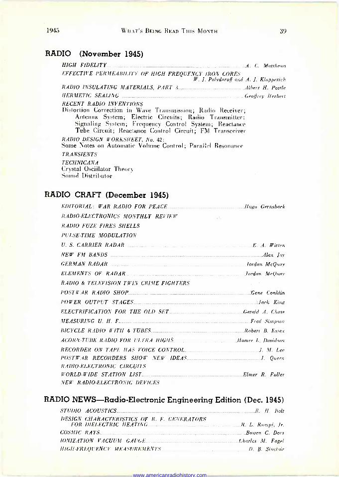
1945 WHAT'S BEING READ THIS MONTH 39
RADIO (November 1945) HIGH FIDELITY... _ A. C. Matthews EFFECTIVE PERMEABILITY OF HIGH FREQUENCY IRON CORES
W. J. Polydoroff and A. J. Klapperich RADIO INSULATING MATERIALS, PART 3 Albert H. Postle HERMETIC SEALING Geoffrey Herbert RECENT RADIO INVENTIONS Distortion Correction in Wave Transmission; Radio Receiver;
Antenna System; Electric Circuits; Radio Transmitter; Signaling System; Frequency Control System; Reactance Tube Circuit; Reactance Control Circuit; FM Transceiver
RADIO DESIGN WORKSHEET, No. 42: Some Notes on Automatic Volume Control; Parallel Resonance TRANSIENTS
TECHNICANA Crystal Oscillator Theory Sound Distributor
RADIO CRAFT (December 1945) EDITORIAL: WAR RADIO FOR PEACE Hugo Gernsback
RADIO -ELECTRONICS MONTHLY REVIEW
RADIO FUZE FIRES SHELLS
PULSE -TIME MODULATION
U. S. CARRIER RADAR E. A. Witten
NEW FM BANDS Alan Jay
GERMAN RADAR Jordan Mc Quay
ELEMENTS OF RADAR . Jordan Mr Quay
RADIO & TELEVISION TWIN CRIME FIGHTERS
POSTWAR RADIO SHOP Gene Conklin
POWER OUTPUT STAGES 'Jack King
ELECTRIFICATION FOR THE OLD SET Gerald A. Chase
MEASURING U. H. F Fred Simpson
BICYCLE RADIO WITH 4 TUBES Robert B. Essex
ACORN -TUBE RADIO FOR ULTRA HIGHS Homer L. Davidson
RECORDER ON TAPE HAS VOICE CONTROL J. M. Lee
POSTWAR RECORDERS SHOW NEW IDEAS...__ I. Queen
RADIO -ELECTRONIC CIRCUITS
WORLD-WIDE STATION LIST Elmer R. Fuller NEW RADIO -ELECTRONIC DEVICES
RADIO NEWS-Radio-Electronic Engineering Edition (Dec. 1945) STUDIO ACOUSTICS R. H. Bolt
DESIGN CHARACTERISTICS OF R. F. GENERATORS FOR DIELECTRIC HEATING R. L. Rumpf, Jr.
COSMIC RAYS Bowen C. Dees
IONIZATION VACUUM GAUGE Charles M. Fogel HIGH -FREQUENCY MEASUREMENTS D. R. Sinclair
www.americanradiohistory.com

THE RADIO ENGINEERS' DIGEST
RADIO NEWS (December 1945) BUILD YOUR OWN V.H.F. I'll -AM RECEIVER Art Rattray
WAVE GUIDES S. J. Mallory
HAM RADIO TODAY AND TOMORROW "Reg" Washburn, ex-2AUS, and "Archie" Williams, W80DX
FM FOR HAM USE Ray Frank, W9JU
INTERNATIONAL SHORT-WAVE Kenneth R. Boord
THE AUDIO CHANALYST A. Liebscher
LET'S TALK SHOP Joe Marty, Jr.
MICROFARAD METERS-THEIR ADVANTAGES AND LIMITATIONS..Rufus P. Turner
FUNCTIONS OF VIDEO CIRCUIT Edward M. Noll
PRACTICAL RADIO COURSE -(IJred A. Ghirardi
PENTODE vs. TRIODE OPERATION Herbert S. Brier
FOR THE RECORD By the Editor
SPOT RADIO NEWS Fred Hamlin
PLASTICS IN RADIO Leon Laden
QTC Carl Coleman
THE PROXIMITY FUSE FM RADIO RELAY J. M. Lee
SERVICE (November 1945) CRYSTAL -CONTROLLED OSCILLATORS J. George Stewart
CRYSTAL FILTERS USED IN COMMUNICATIONS RECEIVERS Thomas T. Donald
C -R OSCILLOGRAPHS (Applications ... Servicing ... Part V) S. J. Murcek
ELECTRONIC ALARM SYSTEMS Willard Moody
1-F AMPLIFIERS L. E. Edwards
OLD TIMER'S CORNER SER -CUITS Henry Howard
SERVICING HELPS (Recentering Loudspeaker Cones) Frank C. Keene
SUPERHETERODYNE MIXERS (Part II) Martin W. Elliott
VOL( TIE AND TONE CONTROL RESISTORS (Part f\ of a Series on Receiver Components) Alfred A. Ghirardi
TELEVISION (December 1945)
UNION PICTURE IN TELEVISION _ Clary Gannon
STUDIO CONTROL BOARD EQUIPME.\ T Herbert Taylor
CLEVELAND TELEVISION OUTLOOK - Gilbert Winfield
TELECASTING A FOOTBALL GAME Bob Stanton
SO YOU THINK YOU KNOW THE MEDIUM Ben Feiner
AUDIENCE PANEL ONE MAN'S REFLECTIONS Dr. Raymond Wilmotte
ADVERTISING AGENCIES AND FILM DEPARTMENTS H. G. Christensen
www.americanradiohistory.com

HUDSON AMERICAN'S complete line of post - war
Marine Radio Telephones are
the result of 20 years of
hard-won experience in de-
signing and manufacturing
fine communications equip-
ment. Hudson American
Marine Radio Telephones are
engineered by men who are
themselves yachtsmen and
know the marine field in-
timately. You will find one
of these models particularly
adapted to your needs,
whether you own a large or
small craft.
Modern in styling, handsome
in appearance, housed in one
compact durable unit, Hud-
son American Marine Radio
Telephones are the finest
available.
To insure having the best,
equip your craft, new or old,
with a HUDSON AMERI-
CAN MARINE RADIO TELEPHONE.
Write for detailed information M-12
JN aF L' HUDSON AMERICAN CORPORATION
36, Wheeler, Sport Fishing Cruiser HUDSON equipped
Fred C. Smith, Vice-Pres. Bowery Savings Bank, owner of this craft says- "Since restrictions were removed 1 have found much pleasure in renewing old acquaintances made on the air before the war through my Hudson Marine Radio Telephone. It functions as perfectly today as it did when installed years ago."
The Distinctive "CORSAIR"
Subsidiary of Reeves -Ely Laboratories, Inc.
PORAj 25 WEST 43rd STREET, NEW YORK 18, N.Y.
www.americanradiohistory.com
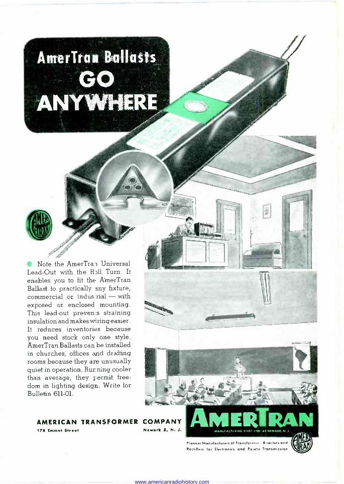
AmerTran Ballasts
GO ANYWHERE
Note the AmerTran Universal Lead -Out with the RDll Turn. It enables you to fit the AmerTran Ballast to practically any fixture, commercial or indus -rial - with exposed or enclosed mounting. This lead -out preven:s straining insulation and makes wiring easier. It reduces inventories because you need stock only one style. AmerTran Ballasts can be installed in churches, offices and drafting rooms because they am unusually quiet in operation. Running cooler than average, they permit free- dom in lighting design. Write for Bulletin 611-01. =. :
AMERICAN TRANSFORMER COMPANY 17R Emmet Street Newark 5, N. J. MANUFACTURING SINCE r Al NEWARK, N 1
Pioneer Manufacturers of Transferner. Reactors end Rectifiers for Electronics and Powers Trt riimitsion
www.americanradiohistory.com