eycon_ha029280_5
TRANSCRIPT

EUROTHERM®
®
Eyco
n™
10/2
0V
isual
Super
viso
r
Handbook


© 2008 Eurotherm Limited
All rights are strictly reserved. No part of this document may be reproduced, modified, or transmitted in any formby any means, nor may it be stored in a retrieval system other than for the purpose to act as an aid in operating theequipment to which the document relates, without the prior written permission of Eurotherm limited.
Eurotherm Limited pursues a policy of continuous development and product improvement. The specifications inthis document may therefore be changed without notice. The information in this document is given in good faith,but is intended for guidance only. Eurotherm Limited will accept no responsibility for any losses arising fromerrors in this document.
EUROTHERM®
®
Declaration of Conformity
Manufacturer's name: Eurotherm Limited
Manufacturer's address: Faraday Close, Worthing, West Sussex,BN13 3PL, United Kingdom
Product type: Visual Supervisor
Models: Eycon-10 Status level A1 and aboveEycon-20 Status level A1 and above
Safety specification: EN61010-1: 2001
EMC emissions specification: EN61326-1: 1997 Class A(including amendments A1, A2 and A3)
EMC immunity specification: EN61326-1: 1997 Industrial locations(including amendments A1, A2 and A3)
Eurotherm Limited hereby declares that the above products conform to the safety and EMCspecifications listed. Eurotherm Limited further declares that the above products complywith the EMC Directive 89 / 336 / EEC amended by 93 / 68 / EEC, and also with the LowVoltage Directive 73 / 23 / EEC.
Signed: Dated:
Signed for and on behalf of Eurotherm LimitedWilliam Davis
(General Manager)IA249986U700 Issue 2 Aug 06 (CN22697)

EUROTHERM®
®40

ContentsPage 1
HA029280Issue 5 Mar 08
VISUAL SUPERVISOR HANDBOOK
VISUAL SUPERVISOR
HANDBOOK
LIST OF CHAPTERSSection Page1 INSTALLATION...................................................................................... 1- 12 GETTING STARTED .............................................................................. 2 - 13 OPERATION ........................................................................................ 3 - 14 MANAGEMENT .................................................................................. 4 - 15 CUSTOMISING ................................................................................... 5 - 16 ADMINISTATIVE FUNCTIONS ............................................................... 6 - 17 REMOTE ACCESS ................................................................................ 7 - 18 THE CONTROL CONFIGURATOR .......................................................... 8 - 19 PREVENTIVE MAINTENANCE ............................................................... 9 - 110 PROFIBUS OPTION ............................................................................ 10 - 111 FLUSH MOUNTING OPTION .............................................................. 11 - 1A SPECIFICATION ................................................................................... A - 1B OPTIONS UPDATE ............................................................................... B - 1C REFERENCE ......................................................................................... C - 1
EFFECTIVITYThis manual refers to instruments fitted with software version number V2.1
RELATED MANUALSThe Setpoint Program Editor Handbook ........................................ HA261134U005The UserScreen Editor Handbook ................................................. HA260749U005The LIN Blocks Reference Manual ................................................ HA082375U003LINtools On-line user guide ......................................................... RM263001U055The LIN/ALIN Installation and User Guide .................................... HA082429U005The T2550 DIN rail controller User Manual .......................................... HA028898Modbus/Profibus communications handbook ........................................ HA028014
All registered and unregistered trademarks are properties of their respective holders.

HA029280Issue 5 Mar 08
ContentsPage 2
VISUAL SUPERVISOR HANDBOOK
LIST OF CONTENTSSection Page
SAFETY NOTES ........................................................................................... 1 - 1SYMBOLS USED ON THE EQUIPMENT LABELLING ......................................... 1 - 1PREVENTIVE MAINTENANCE ....................................................................... 1 - 2Chapter 1: INSTALLATION ..............................................................1 - 31.1 UNPACKING ........................................................................................ 1 - 31.2 MECHANICAL INSTALLATION ............................................................... 1 - 31.3 ELECTRICAL INSTALLATION ................................................................... 1 - 6
1.3.1 Supply voltage wiring.................................................................... 1 - 6POWER REQUIREMENTS .............................................................. 1 - 6
1.3.2 EIA485 connections ...................................................................... 1 - 7LED INDICATORS.......................................................................... 1 - 7
1.3.3 ETHERNET (100/10 Base-T) Connector ........................................... 1 - 81.3.4 USB Connector ............................................................................. 1 - 81.3.5 Wiring the Visual Supervisor to I/O units ........................................ 1 - 91.3.6 Profibus wiring ........................................................................... 1 - 10
Chapter 2: GETTING STARTED ........................................................2 - 12.1 SWITCH-ON AND THE OPENING DISPLAY ............................................ 2 - 1
2.1.1 Switch on ..................................................................................... 2 - 12.1.2 The standard interface ................................................................... 2 - 1
MAIN PANE ................................................................................. 2 - 2PROGRAM PANE.......................................................................... 2 - 2ALARM PANE ............................................................................... 2 - 2LOGGING PANE .......................................................................... 2 - 2ACCESS PANE ............................................................................. 2 - 2RECIPE PANE ............................................................................... 2 - 2NAVIGATION KEYS ...................................................................... 2 - 3USER DEFINED KEYS .................................................................... 2 - 3
2.1.3 The opening display ...................................................................... 2 - 42.2 THE MAIN PANE .................................................................................. 2 - 5
2.2.1 Information display ....................................................................... 2 - 52.2.2 Information entry ........................................................................... 2 - 5
2.3 THE POP-UP MENU ............................................................................... 2 - 62.4 THE PROGRAM PANE ........................................................................... 2 - 7
2.4.1 Displaying program status ............................................................. 2 - 7WITH NO PROGRAM LOADED ..................................................... 2 - 7WITH A PROGRAM LOADED......................................................... 2 - 7
2.4.2 Programmer menu access .............................................................. 2 - 72.5 THE PROGRAMMER MENU ................................................................... 2 - 82.6 THE ALARM PANE................................................................................. 2 - 9
2.6.1 Alarm state indication ................................................................... 2 - 9ACTIVE MESSAGE DISPLAY ......................................................... 2 - 10
2.6.2 Responding to alarms .................................................................. 2 - 10DO NOTHING ........................................................................... 2 - 10ALARM HISTORY PAGE ............................................................... 2 - 10TWO LINE DISPLAY..................................................................... 2 - 11ALARM ACKNOWLEDGEMENT ................................................... 2 - 11
2.7 LOGGING PANE ................................................................................ 2 - 122.8 ACCESS PANE ................................................................................... 2 - 12
2.8.1 Gaining access ........................................................................... 2 - 12STANDARD ACCESS ................................................................... 2 - 12

ContentsPage 3
HA029280Issue 5 Mar 08
VISUAL SUPERVISOR HANDBOOK
LIST OF CONTENTS (Cont.)Section PageChapter 3: OPERATION..................................................................3 - 13.1 RUNNING A PROGRAM ....................................................................... 3 - 1
3.1.1 Running a program now ................................................................ 3 - 13.1.2 Running from a point .................................................................... 3 - 33.1.3 Scheduling a program ................................................................... 3 - 4
3.1.3.1 SPECIFYING THE PROGRAM START DATE ......................... 3 - 53.1.3.2 SPECIFYING THE PROGRAM START TIME .......................... 3 - 53.1.3.3 CHANGING THE NUMBER OF ITERATIONS (RUNS) .......... 3 - 6
3.1.4 Segment skip ................................................................................ 3 - 73.1.4.1 SEGMENT TRANSITION CONSEQUENCES ...................... 3 - 7FROM DWELL, SET OR SERVO (SP OR PV) TO ANY OTHER TYPE ..... 3 - 7FROM RAMP TO SET .................................................................... 3 - 7FROM RAMP TO DWELL ............................................................... 3 - 7FROM RAMP TO END (STARTING VALUES) ..................................... 3 - 7FROM RAMP TO COMPLETE (INFINITE DWELL) ............................... 3 - 7TO RAMP FROM ANY OTHER TYPE ............................................... 3 - 7
3.2 HOLDING AND ABORTING A PROGRAM .............................................. 3 - 83.2.1 Holding a program ....................................................................... 3 - 83.2.2. Aborting a program ...................................................................... 3 - 8
3.3 MONITORING A PROGRAM ................................................................. 3 - 93.3.1 The monitor facility ........................................................................ 3 - 93.3.2 The preplot facility ...................................................................... 3 - 10
STANDARD DISPLAY MODE......................................................... 3 - 10REVIEW MODE .......................................................................... 3 - 10
3.4 LOGGING DATA ................................................................................ 3 - 113.4.1 Types of files .............................................................................. 3 - 11
ASCII ......................................................................................... 3 - 11UHH .......................................................................................... 3 - 11
3.4.2 Name types ................................................................................ 3 - 11TEXT .......................................................................................... 3 - 11HOURLY ..................................................................................... 3 - 11DAILY ......................................................................................... 3 - 11SEQUENCE ............................................................................... 3 - 11
3.4.3 The Manage facility .................................................................... 3 - 12ARCHIVE EXPORT ....................................................................... 3 - 12
3.4.4 Data integrity ............................................................................. 3 - 123.5 ALARMS / MESSAGE RESPONSE ........................................................ 3 - 13
TIME REPRESENTATION .............................................................. 3 - 133.5.1 Alarm history page ..................................................................... 3 - 13
TWO LINE DISPLAY..................................................................... 3 - 14FILTER KEYS ................................................................................ 3 - 14ACK KEY ................................................................................... 3 - 15ARCHIVE ................................................................................... 3 - 15
3.5.2 Alarm/Message Acknowledgement .............................................. 3 - 15ALARMS .................................................................................... 3 - 15MESSAGES ................................................................................ 3 - 15
3.5.3. Adding notes to alarm history ...................................................... 3 - 153.5.4 Alarm history archive .................................................................. 3 - 163.5.5 Alarm summary page .................................................................. 3 - 163.5.6 Event Log ................................................................................... 3 - 17
TWO LINE DISPLAY..................................................................... 3 - 173.6 AREA AND GROUP DISPLAYS .............................................................. 3 - 18
3.6.1 Overview ................................................................................... 3 - 18TREND DISPLAYS ........................................................................ 3 - 18ALARM INDICATION .................................................................. 3 - 18

HA029280Issue 5 Mar 08
ContentsPage 4
VISUAL SUPERVISOR HANDBOOK
LIST OF CONTENTS (Cont.)Section Page
3.6.2 Function block faceplates ............................................................. 3 - 20RAMP FACEPLATES ..................................................................... 3 - 20PID FACEPLATES ......................................................................... 3 - 21
3.6.3 Display modes ............................................................................ 3 - 21FACEPLATE DISPLAY .................................................................... 3 - 22NUMERIC DISPLAY ..................................................................... 3 - 22VERTICAL BARGRAPH ................................................................. 3 - 22HORIZONTAL BARGRAPH ........................................................... 3 - 23VERTICAL TREND WITH FACEPLATE .............................................. 3 - 23VERTICAL TREND - FULL WIDTH ................................................... 3 - 25HORIZONTAL TREND WITH FACEPLATE ....................................... 3 - 25HORIZONTAL TREND - FULL WIDTH ............................................. 3 - 26
3.7 DOWNLOADING RECIPES .................................................................. 3 - 27RECIPE SET SELECTION............................................................... 3 - 28
3.7.1 Download procedure................................................................... 3 - 28LOADING THE RECIPE ................................................................ 3 - 28SELECTING A RECIPE LINE .......................................................... 3 - 29SELECTING A RECIPE.................................................................. 3 - 29
3.7.2 Monitoring the recipe .................................................................. 3 - 29RECIPE STATUS PAGE .................................................................. 3 - 29RECIPE MONITOR PAGE ............................................................. 3 - 30
3.8 BATCHES ........................................................................................... 3 - 313.8.1 Batch loading ............................................................................. 3 - 313.8.2 Recipe selection .......................................................................... 3 - 313.8.3 Batch customising ....................................................................... 3 - 313.8.4 Batch initiation ............................................................................ 3 - 323.8.5 Batch monitoring ......................................................................... 3 - 323.8.6 Batch Hold ................................................................................. 3 - 323.8.7 Batch Abort ................................................................................ 3 - 323.8.8 Batch Create .............................................................................. 3 - 33
Chapter 4: MANAGEMENT .............................................................4 - 14.1. EDITING A PROGRAM .......................................................................... 4 - 1
4.1.1 INTRODUCTION .......................................................................... 4 - 1CREATING A PROGRAM ............................................................... 4 - 1EDITING A PROGRAM .................................................................. 4 - 1
4.1.2 Program Editor Page access ........................................................... 4 - 34.1.3 Changing a setpoint ...................................................................... 4 - 4
CHANGING RAMP TYPE .............................................................. 4 - 4TERMINOLOGY ............................................................................ 4 - 4TO CHANGE THE TYPE OF RAMP ................................................. 4 - 5CHANGING SETPOINT VALUE ...................................................... 4 - 6
4.1.4 Changing a segment ..................................................................... 4 - 7CHANGING SEGMENT IDENTIFIER ............................................... 4 - 7CHANGING SEGMENT DURATION............................................... 4 - 8
4.1.5 Inserting/deleting segment ............................................................. 4 - 8INSERTING A NULL SEGMENT ...................................................... 4 - 8DELETING A SEGMENT ................................................................ 4 - 9
4.1.6 Changing hold back properties ...................................................... 4 - 9CHOOSING THE SETPOINT ........................................................ 4 - 10CHANGING HOLD BACK MODE ................................................ 4 - 10CHANGING HOLDBACK VALUES ................................................ 4 - 10
4.1.7 Changing program properties ...................................................... 4 - 11CHANGING PROGRAM NAMES................................................. 4 - 11CHANGING RATE UNITS ............................................................ 4 - 12CHOOSING END-OF-RUN ACTION ............................................ 4 - 12CHANGING DEFAULT ITERATIONS .............................................. 4 - 13
4.1.8 Changing setpoint names ............................................................. 4 - 134.1.9 Segment timing display ............................................................... 4 - 14
ContentsPage 5
HA029280Issue 5 Mar 08
VISUAL SUPERVISOR HANDBOOK
LIST OF CONTENTS (Cont.)Section Page4.2 LOGGING GROUPS OF DATA ............................................................. 4 - 15
4.2.1 Log initiation .............................................................................. 4 - 15LOG CONFIGURATION .............................................................. 4 - 16
4.2.2 FTP Transfer ................................................................................ 4 - 18MULTIPLE COPY MODE ............................................................... 4 - 18SINGLE COPY MODE ................................................................. 4 - 18CONFIGURATION ...................................................................... 4 - 18
4.3 MANAGING AN APPLICATION ........................................................... 4 - 194.3.1 Application summary page .......................................................... 4 - 204.3.2 Application manager page .......................................................... 4 - 204.3.3 Stopping an application .............................................................. 4 - 214.3.4 Saving application data .............................................................. 4 - 224.3.5 Unloading an application ............................................................ 4 - 224.3.6 Loading or loading and running an application ............................. 4 - 23
APPLICATION SELECTION ........................................................... 4 - 23APPLICATION LOADING ............................................................. 4 - 23
4.3.7 Deleting an application ............................................................... 4 - 234.3.8 Function Block Manager .............................................................. 4 - 24
ALPHA-NUMERIC BLOCK DISPLAY................................................ 4 - 26FUNCTION BLOCK DETAILS ........................................................ 4 - 27
4.4 CONTROLLING ACCESS ..................................................................... 4 - 274.4.1 First-time access .......................................................................... 4 - 284.4.2 Editing the passwords.................................................................. 4 - 284.4.3 User ID system ............................................................................ 4 - 30
CHANGING TO THE USER ID SYSTEM ........................................ 4 - 30USER ID MANAGEMENT ............................................................ 4 - 31
4.5 SETTING UP AND RE-SETTING THE INSTRUMENT ................................. 4 - 354.5.1 Editing communications parameters .............................................. 4 - 35
SOFTWARE PARAMETER EDITING ................................................ 4 - 36PROTOCOLS AVAILABLE .............................................................. 4 - 36TALK-THRU ................................................................................. 4 - 36ETHERNET.................................................................................. 4 - 37MODBUS/TCP ........................................................................... 4 - 38
4.5.2 Setting the start-up strategy .......................................................... 4 - 39HOT/COLD START CRITERIA ........................................................ 4 - 39START-UP STRATEGY PAGE .......................................................... 4 - 39CHANGING START-UP VALUES .................................................... 4 - 40
4.5.3 Resetting the clock ....................................................................... 4 - 41CLOCK SETUP PAGE ACCESS ..................................................... 4 - 41CHANGING DATE AND TIME ..................................................... 4 - 41TIME CHANGING ...................................................................... 4 - 42
4.5.4 Changing language and date/time formats ................................... 4 - 42LANGUAGE ............................................................................... 4 - 43DATE FORMAT ........................................................................... 4 - 43TIME FORMAT ............................................................................ 4 - 43
4.5.5 Setting up the panel display ......................................................... 4 - 44ACCESS TO THE PANEL SETUP PAGE........................................... 4 - 44DISPLAY BRIGHTNESS SETTINGS ................................................. 4 - 44TIME-OUTS................................................................................. 4 - 45DATA ENTRY .............................................................................. 4 - 45
4.6 CLONING AN INSTRUMENT ............................................................... 4 - 464.6.1 Accessing the cloning page ......................................................... 4 - 464.6.2 Cloning application data ............................................................. 4 - 47
EXPORTING APPLICATION DATA ................................................. 4 - 47 IMPORTING APPLICATION DATA ................................................ 4 - 47

HA029280Issue 5 Mar 08
ContentsPage 6
VISUAL SUPERVISOR HANDBOOK
LIST OF CONTENTS (Cont.)Section Page
4.6.3 Cloning system (instrument) data .................................................. 4 - 48SELECTING SYSTEM DATA .......................................................... 4 - 48EXPORTING SYSTEM DATA ......................................................... 4 - 48 IMPORTING SYSTEM DATA ........................................................ 4 - 48
4.6.4 Cloning both application and system data (ALL) ............................. 4 - 494.7 FILE MANAGER .................................................................................. 4 - 50
4.7.1 Stopping the application .............................................................. 4 - 504.7.2 Calling the file manager .............................................................. 4 - 504.7.3 File Copy and Delete ................................................................... 4 - 514.7.4 Reloading the application ............................................................ 4 - 52
4.8 RECIPE MANAGEMENT ...................................................................... 4 - 524.8.1 Creating recipe files .................................................................... 4 - 524.8.2 Recipe editing ............................................................................ 4 - 52
ADD RECIPE LINE ....................................................................... 4 - 52ADD A VARIABLE ........................................................................ 4 - 53TAG REFERENCES ...................................................................... 4 - 53RECIPE VALUE ............................................................................ 4 - 53ADDING A RECIPE ..................................................................... 4 - 53DELETING RECIPES ..................................................................... 4 - 53SAVING RECIPES ........................................................................ 4 - 54 RECIPE FILE PROPERTIES ............................................................. 4 - 54
4.8.3 Capturing a Recipe ..................................................................... 4 - 544.9 OEM FEATURES .................................................................................. 4 - 55
4.9.1 Intellectual Property Right Protection (IPRP) ..................................... 4 - 55MODIFYING IPRP SETTINGS ....................................................... 4 - 55
4.10 BATCH MAINTNEANCE .................................................................... 4 - 56Chapter 5: CUSTOMISING...............................................................5 - 15.1 INTRODUCTION................................................................................... 5 - 1
5.1.1 The dictionaries ............................................................................ 5 - 15.1.2 Panel navigation and database names ............................................ 5 - 2
5.2 THE SYSTEM TEXT DICTIONARY ............................................................. 5 - 25.2.1 File structure .................................................................................. 5 - 25.2.2 Editing system text ......................................................................... 5 - 35.2.3 New language versions ................................................................. 5 - 35.2.4 The dictionary ............................................................................... 5 - 35.2.5 Panel customisation using the dictionary ......................................... 5 - 245.2.6 Alarm/event customisation using the dictionary ............................. 5 - 26
5.3 THE ERROR TEXT DICTIONARY ............................................................ 5 - 275.3.1 Editing error messages ................................................................ 5 - 285.3.2 Creating new language error text ................................................. 5 - 28
PROCEDURE .............................................................................. 5 - 285.4 THE EVENT TEXT DICTIONARY ............................................................ 5 - 29
5.4.1 Editing Event Messages ............................................................... 5 - 335.4.2 Creating new language event text ................................................ 5 - 33
PROCEDURE .............................................................................. 5 - 335.4.3 Event priorities ............................................................................ 5 - 33
5.5 THE USER TEXT DICTIONARY ............................................................... 5 - 345.6 THE PROGRAMMER TEXT DICTIONARY ................................................ 5 - 345.7 PANEL NAVIGATION .......................................................................... 5 - 35
5.7.1 The Panel Navigation file ............................................................. 5 - 35THE VERSIONS .......................................................................... 5 - 35AUDITOR OPTION VERSIONS ..................................................... 5 - 39
5.7.2 Editing the _default.pnl file ........................................................... 5 - 42

ContentsPage 7
HA029280Issue 5 Mar 08
VISUAL SUPERVISOR HANDBOOK
LIST OF CONTENTS (Cont.)Section Page
5.7.3 Line types ................................................................................... 5 - 43PANEL AGENT DECLARATION..................................................... 5 - 43PANEL DRIVER DECLARATION ..................................................... 5 - 44HOME PAGE DECLARATION ....................................................... 5 - 45 ROOT PAGE DECLARATION ....................................................... 5 - 45 INITIAL PAGE DECLARATION ...................................................... 5 - 45
5.7.4 Agent types ................................................................................ 5 - 465.8 DATABASE NAMES ............................................................................. 5 - 48
5.8.1 Function block names .................................................................. 5 - 485.8.2 Alarm names .............................................................................. 5 - 485.8.3 Enumerations .............................................................................. 5 - 49
TAGS ......................................................................................... 5 - 495.9 FORM FILES ........................................................................................ 5 - 50
5.9.1 Report forms ............................................................................... 5 - 50UYF FILE ENTRIES ....................................................................... 5 - 51
5.9.2 Alarm forms ............................................................................... 5 - 54EXAMPLE ................................................................................... 5 - 54
5.10 RECIPE FILES ..................................................................................... 5 - 555.10.1 Basic Recipe File ....................................................................... 5 - 55
FILE HEADER .............................................................................. 5 - 55TITLE LINE .................................................................................. 5 - 56VARIABLE LINES .......................................................................... 5 - 56BASIC FILE EXAMPLE ................................................................... 5 - 56
5.10.2 More complex files .................................................................... 5 - 57MULTI-LINE FILES ......................................................................... 5 - 57FILES WITH OPTIONAL CAPTURE VARIABLES ................................ 5 - 57FILES WITH OPTIONAL MONITOR VARIABLES .............................. 5 - 58
5.11 WRITABLE DICTIONARY .................................................................... 5 - 585.12 THE RECIPE DICTIONARY .................................................................. 5 - 595.13 THE BATCH DICTIONARY ................................................................... 5 - 60
5.13.1 Example ................................................................................... 5 - 605.14 BATCH FILES ...................................................................................... 5 - 61
5.14.1 File Header ............................................................................... 5 - 615.14.2 Batch Phases ............................................................................. 5 - 62
5.15 DATABASE CHANGE AUDIT TRAILING ................................................ 5 - 635.15.1 Header Line ............................................................................... 5 - 635.15.2 Item Lines .................................................................................. 5 - 63
Chapter 6: ADMINISTRATIVE FUNCTIONS .......................................6 - 16.1 NETWORK AUDIT TRAIL ........................................................................ 6 - 1
6.1.1 Modes ......................................................................................... 6 - 26.1.2 Configuration (Provider) ................................................................ 6 - 2
CONSUMER SELECTION .............................................................. 6 - 2AUDIT TRAIL FILTERING ................................................................. 6 - 2PARAMETERS ............................................................................... 6 - 2
6.1.3 User ID control .............................................................................. 6 - 3SECURITY ACCESS DISPLAY PAGE ................................................. 6 - 3EXPIRES ....................................................................................... 6 - 5SCREEN KEYS .............................................................................. 6 - 5
6.2 ELECTRONIC SIGNATURES.................................................................. 6 - 106.2.1 Enabling electronic signatures ...................................................... 6 - 106.2.2 Signature Configuration ............................................................... 6 - 11
ACCESS LEVELS ......................................................................... 6 - 11

HA029280Issue 5 Mar 08
ContentsPage 8
VISUAL SUPERVISOR HANDBOOK
LIST OF CONTENTS (Cont.)Section PageChapter 7: REMOTE ACCESS ...........................................................7 - 17.1 FTP ...................................................................................................... 7 - 1
7.1.1 FTP logon ..................................................................................... 7 - 1TIMEOUT ..................................................................................... 7 - 1
7.1.2 File system.................................................................................... 7 - 17.1.3 Archive File Transfer ...................................................................... 7 - 1
Chapter 8: THE CONTROL CONFIGURATOR ....................................8 - 18.1 OVERVIEW .......................................................................................... 8 - 18.2 PREPARATION ...................................................................................... 8 - 1
8.2.1 Configurator mode selection .......................................................... 8 - 18.2.2 Control efficiency selection ............................................................ 8 - 1
8.3 RUNNING THE CONFIGURATOR .......................................................... 8 - 28.3.1 Initial menu access ........................................................................ 8 - 28.3.2 The Initial menu ............................................................................ 8 - 38.3.3 Quitting the VDU package & CPU configuration mode...................... 8 - 3
8.4 DATABASE CONFIGURATION ............................................................... 8 - 38.4.1 MAKE .......................................................................................... 8 - 4
BLOCK OVERVIEW ....................................................................... 8 - 4CONNECTION TYPES IN A CPU DATABASE .................................. 8 - 8
8.4.2 COPY .......................................................................................... 8 - 88.4.3 DELETE ......................................................................................... 8 - 88.4.4 INSPECT ...................................................................................... 8 - 98.4.5 NETWORK................................................................................... 8 - 98.4.6 Utilities ....................................................................................... 8 - 10
START, STOP UTILITIES ................................................................. 8 - 10SAVE UTILITY .............................................................................. 8 - 10LOAD UTILITY ............................................................................. 8 - 10FILE UTILITY ................................................................................ 8 - 11
8.4.7 ALARMS .................................................................................... 8 - 118.4.8 ALARM LOG .............................................................................. 8 - 118.4.8 EVENT LOG ............................................................................... 8 - 11
8.5 MODBUS CONFIGURATION ............................................................. 8 - 128.5.1 GW index .................................................................................. 8 - 128.5.2 MODE ....................................................................................... 8 - 128.5.3 INTERFACE ................................................................................ 8 - 138.5.4 SETUP ........................................................................................ 8 - 13
SERIAL MASTER .......................................................................... 8 - 13SERIAL SLAVE ............................................................................. 8 - 13TCP MASTER .............................................................................. 8 - 13TCP SLAVE ................................................................................. 8 - 13
8.5.5 TABLES ....................................................................................... 8 - 15TABLES LIST ................................................................................ 8 - 15TABLE MENUS ............................................................................ 8 - 17
Chapter 9: PREVENTIVE MAINTENANCE .........................................9 - 19.1 BATTERY REPLACEMENT ........................................................................ 9 - 1
9.1.1 Replacement procedure ................................................................. 9 - 19.2 TOUCH SCREEN CALIBRATION ............................................................. 9 - 2Chapter 10: PROFIBUS MASTER OPTION ......................................10 - 110.1 INTRODUCTION............................................................................... 10 - 110.2 INSTALLATION.................................................................................. 10 - 1
10.2.1 Mechanical installation .............................................................. 10 - 110.2.2 Pinout details ............................................................................ 10 - 1
10.3 FUNCTION BLOCKS ......................................................................... 10 - 410.3.1 GWProfM CON ....................................................................... 10 - 4

ContentsPage 9
HA029280Issue 5 Mar 08
VISUAL SUPERVISOR HANDBOOK
Chapter 11: FLUSH MOUNTING OPTION INSTALLATION ...............11 - 111.1 UNPACKING .................................................................................... 11 - 111.2 MECHANICAL INSTALLATION ........................................................... 11 - 1
11.2.1 Specification ............................................................................ 11 - 2Appendix A: TECHNICAL SPECIFICATION ........................................ A - 1General specification .................................................................................... A - 1Communications specification ........................................................................ A - 3Function Blocks supported ............................................................................. A - 4Appendix B: OPTIONS UPDATE ......................................................B - 1B1 INTRODUCTION .................................................................................... B - 1B2 SOFTWARE OPTIONS UTILITY ACCESS ................................................... B - 1Appendix C: REFERENCE .................................................................C - 1C1 ASCII CODES........................................................................................ C - 1C2 GLOSSARY ........................................................................................... C - 2Index ............................................................................................... i -1
LIST OF CONTENTS (Cont.)Section Page

HA029280Issue 5 Mar 08
ContentsPage 10
VISUAL SUPERVISOR HANDBOOK
This page is deliberately left blank

Chapter 1Page 1 - 1
VISUAL SUPERVISOR HANDBOOK
HA029280Issue 5 Mar 08
SAFETY NOTES
WARNING!This unit is intended for use with low voltage dc supplies. Connection of mains (line) supply voltages willnot only damage the unit, but may also cause an electrical shock hazard to be present at operator accessiblesurfaces.
WARNING!The supply voltage connector has two 0V pins, commoned together by the circuit board backplane, and two24V (nom) pins which are also shorted together internally. This allows easy ‘daisy-chaining’ of multipleunits. Two separate power supply units may not be connected as to do so may result in damage to the unit,and/or a potential fire or explosion hazard.
CAUTIONLocal lightning protection must be fitted if the dc power supply unit is located more than 30 metres from thevisual supervisor(s) it is supplying.
Note: in order to comply with the requirements of safety standard BS EN61010, the recorder shall have oneof the following as a disconnecting device, fitted within easy reach of the operator, and labelled as the discon-necting device.a. A switch or circuit breaker which complies with the requirements of IEC947-1 and IEC947-3b. A separable coupler which can be disconnected without the use of a toolc. A separable plug, without a locking device, to mate with a socket outlet in the building.
1. If a hazard could arise from an operator’s reliance on a value displayed by the equipment, the display must givean unambiguous indication (e.g. a flashing alarm) whenever the value is over range or under range.
2. Where conductive pollution (e.g. condensation, carbon dust) is likely, adequate air conditioning/filtering/sealingetc. must be installed in the equipment enclosure.
3 The equipment is designed for process monitoring and supervision in an indoor environment. If the equipment isused in a manner not specified by the manufacturer, the protection provided by the equipment might be impaired.
4. The battery within the unit must not be short circuited. When exhausted, the battery must be disposed of in ac-cordance with local regulations for poly-carbonmonofluoride/lithium cells.
5. When connecting a USB device, it must be plugged directly into the instrument. The use of extension USB leadsmay compromise the unit’s ESD compliance.
6. There are no specific insulation requirements for external circuitry.7. In order to comply with CE requirements, the Protective-conductor terminal must be connected to a protective
conductor.
SYMBOLS USED ON THE EQUIPMENT LABELLINGOne or more of the symbols below may appear as a part of the unit's labelling.
CautionWhen accessing the battery, or setting DIP switches etc. the operator must be at the same electrical potentialas the casing of the instrument.When fitting USB devices, both the operator and the device must be at the same electrical potential as thecasing of the instrument.
! Refer to the manualfor instructions
Protective-conductorterminal
This instrumentfor dc supply only
Ethernet connector
USB connector
Serial communicationsconnector
Precautions against static elec-trical discharge must be takenwhen handling this unit.
For environmental reasons, thisunit must be recycled beforeits age exceeds the number ofyears shown in the circle.

Chapter 1Page 1 - 2
HA029280Issue 5 Mar 08
VISUAL SUPERVISOR HANDBOOK
PREVENTIVE MAINTENANCEThe unit may be cleaned using a lint-free cloth, moistened if necessary with a weak detergent solution. Aggressivecleaning materials such as isopropyl alcohol may not be used as they damage the touch screen.
The average life of the battery is approximately five years. It is recommended that the ‘BadBatt’ flag is set in thedatabase header block, to trigger an instrument alarm when the battery needs to be replaced. The battery should bereplaced as soon as possible after the appearance of this alarm.

Chapter 1Page 1 - 3
VISUAL SUPERVISOR HANDBOOK
HA029280Issue 5 Mar 08
CHAPTER 1: INSTALLATION
Note: See also chapter 10 for installation details for units fitted with the Profibus option and chapter 11 fordetails of the ‘Flush-mounting’ option.
This chapter is intended for use by those responsible for the installation and commissioning of the instrument andconsists of the following sections:1.1 Unpacking1.2 Mechanical installation1.3 Electrical installation
1.1 UNPACKINGThe unit is despatched in a special pack designed to protect it during transit.If the outer box of the pack shows signs of damage, please open it immediately and examine the instrument. If there isevidence of damage, contact the manufacturer’s local representative for instructions. Do not operate the instrument inthe meantime.If the outer box is not damaged, remove the instrument from its packing with all accessories and documentation.Once the unit has been installed, store any internal packing with the external packing in case of future despatch.
1.2 MECHANICAL INSTALLATION
1. Check that the mounting panel is no thicker than 22mm (typically for wood or plastic) and no thinner than 2mm(for steel).
2. In the panel, cut an aperture 138mm x 138mm (small frame) or 281mm x 281mm (large frame). If more than oneinstrument is to be mounted in the panel, the recommended minimum spacings are as shown in figure 1.2a/1.2b.
3. From the front side of the mounting panel, insert the instrument (rear end first) through the aperture.4. Insert the two panel clamps into the rectangular apertures at the sides of the instrument case.5. Whilst ensuring that the sealing gasket is flat against the front of the panel, tighten the screws of the clamps suffi-
ciently to hold the unit firmly in position. IMPORTANT: Do not use excessive force to tighten the screws. It coulddistort the case and render the instrument inoperative.

Chapter 1Page 1 - 4
HA029280Issue 5 Mar 08
VISUAL SUPERVISOR HANDBOOK
1.2 MECHANICAL INSTALLATION (Cont.)
CL
Profibus option(chapter 10)
F3F2F1
F6F5F4
PowerEthernet Serial comms
USBFlash card
Protective-conductorterminal (M4)
Panel cutout138 mm x 138 mm(both -0 + 1 mm)
144.0 mm
144.
0 m
m
87.7 mm
137.
0 m
m137.5 mm
154.5 mm
170.5 mm
6.7 mm
– – + +
Panel thickness: Max = 22 mm; Min = 2 mm
PANEL MOUNTING DETAILS
Installed panel angle: Vertical panels onlyMinimum inter-unit spacing: 50 mm. vertical or horizontal.
Note: where multiple units are mounted in close proximitywith one another, steps must be taken to ensure that theresulting ambient temperature does not exceed the speci-fied maximum operating temperature of 50 degrees Celsius
Fixing Clip(one each side)
Profibus Option(Chapter 10)
Figure 1.2a Small-frame unit mechanical installation

Chapter 1Page 1 - 5
VISUAL SUPERVISOR HANDBOOK
HA029280Issue 5 Mar 08
1.2 MECHANICAL INSTALLATION (Cont.)
Figure 1.2b Large-frame unit mechanical installation
F1 F2 F3 F4 F5 F6 F7 F8 F9
F10 F11 F12 F13 F14 F15 F16 F17 F18
F19 F20 F21 F22 F23 F24 F25 F26 F27
288.0 mm
288.
0 m
m
USB
Panel cutout = 282 mm x 282 mm(both -0 + 1.3mm
281.4 mm
298.4 mm
314.4 mm
SerialCommsEthernet Power
Flash card
––++
PANEL MOUNTING DETAILS
Installed panel angle: Vertical panels onlyMinimum inter-unit spacing: 50 mm. vertical or horizontal.
Note: where multiple units are mounted in close proximitywith one another, steps must be taken to ensure that theresulting ambient temperature does not exceed the speci-fied maximum operating temperature of 50 degrees Celsius
Panel thickness: Max = 22 mm; Min = 2 mm
Protective-conductorterminal (M4)
CL
Fixing Clip(one each side)
70.4 mm
280.
3 m
m
9.6 mm
Profibus option(Chapter 10)
Profibus option(Chapter 10)

Chapter 1Page 1 - 6
HA029280Issue 5 Mar 08
VISUAL SUPERVISOR HANDBOOK
1.3 ELECTRICAL INSTALLATION
Note: Before carrying out any wiring, please read the Safety Notes and warnings preceding this chapter.
1.3.1 Supply voltage wiring
The 24V dc supply voltage wiring is terminated at a four-way connector located on the underside of the unit, as shownin figure 1.2a or 1.2b. The supply wiring should be terminated as shown in figures 1.3.1a, and 1.3.1b, below.
Note: Pins 1 and 2 are internally connected together, as are pins 3 and 4.
POWER REQUIREMENTSVoltage range: 19.2 to 28.8 V dc (24V dc ± 20%)Permissible ripple: 1 V max.Maximum power requirements (at 24 V): Small frame = 20 Watts; Large frame = 24 WattsInrush current: 10AInternal fusing: Not user replaceable
Figure 1.3.1 a Supply voltage wiring(view on underside of instrument)
Front of instrument
19.2 to 28.8V dc
– – + +
Figure 1.3.1b Supply voltage connection examples
24V 0V
24 24 0V 0V 24 24 0V 0V
Linesupply
19.2 to 28.8V dcpower supply
unit
Disconnectdevice
Process supervisor 1(Rear view)
Process supervisor 2(Rear view)
24V 0V
24 24 0V 0V
Linesupply
19.2 to 28.8V dcpower supply
unit
Disconnectdevice
Process supervisor(Rear view)
24V 0V19.2 to 28.8V dc
power supplyunit
Disconnectdevice
Linesupply
Redundant supplies
Daisy-chain unit wiring

Chapter 1Page 1 - 7
VISUAL SUPERVISOR HANDBOOK
HA029280Issue 5 Mar 08
1.3.2 EIA485 connections
This pair of adjacent RJ45 connectors, are located on the underside of the instrument, as shown in figures 1.2a and1.2b. These connectors can be configured, by means of a 4-gang DIP switch each, as Master or Slave. Further sec-tions of the switches allow 120Ω terminating resistors to be switched in and out of circuit. The DIP switches are ac-cessible by removing the access cover at the rear of the unit.
Table 1.3.2a shows the pinout for master and slave connections. Figure 1.3.2 and table 1.3.2b show the switch detailsfor the small frame unit (large frame unit similar).
Note: When using a EIA485 port to communicate with a printer, the master or slave connection should bechosen according to the type of cable being used.
Table 1.3.2a Serial communication port pinout.
Figure 1.3.2Serial communications hardware configuration
120 Ohm terminatingresistor fitted acrosspins 1 and 2
No terminating resistoracross pins 1 and 2
Segment
1
2
4
ON (left) OFF (right)
120 Ohm terminatingresistor fitted acrosspins 7 and 8
No terminating resistoracross pins 7 and 8
Slave Master3 5-wire 3-wire
Table 1.3.2b Communications DIP switch settings
LED INDICATORSThere are two LED indicators associated with the Serial Communications RJ45 connectors:The yellow LED indicates when the unit is transmitting.The green LED illuminates when 5-wire (full duplex) communications is selected (see above).
RxB
RxA
Common
NC
NC
Common
TxB
TxA
TxB
TxA
Common
NC
NC
Common
RxB
RxA
B
A
Common
NC
NC
Common
NC
NC
Pin 5 wireMaster
5 wireSlave
3-WireMaster/Slave
1
2
3
4
5
6
7
8
pin 1
pin 8
RJ 45 plug: View on underside
ON
12
34
ON
12
34
BR2330
Ethernetconnector
Serial communicationsports
Port 1 Port 2
Cover retainingscrew location
CautionThe user must be at the same electrical potentialas the instrument housing when accessinginternal items such as batteries and switches.

Chapter 1Page 1 - 8
HA029280Issue 5 Mar 08
VISUAL SUPERVISOR HANDBOOK
1.3.3 ETHERNET (100/10 Base-T) Connector
The pinout for the Ethernet RJ45 connector is as shown in figure 1.3.3, below. The connector is located on the under-side of the unit, as shown in figure 1.2a and figure 1.2b, above.
Note: The LED indicators integral with the connector socket are not used in this application.
Figure 1.3.3 Ethernet (ELIN) connector pinout.
1.3.4 USB Connector
This connector may be used only for the connection of USB Bulk storage devices (‘memory sticks’). The connectorpinout is shown in figure 1.3.4. The connector is located on the underside of the unit, as shown in figure 1.2a andfigure 1.2b, above.
Note: Compliance with EMC directives cannot be guaranteed if the Bulk Storage Device is connected usingan extension cable.
Figure 1.3.4 USB connector pinout
TxD+1
TxD-
RxD+
RxD-
Not used
Not used
2
3
4
5
6
7
8
Plug shroud wired tocable screen
Not used
Not used
ELIN
pin 1
pin 8
RJ 45 plug: View on underside
1 42 3
View on non-solderend of fixed socket
1234
+ 5VUSB - (D-)USB + (D+)Ground
Pin Definition
CautionBoth the user and the peripheral (e.g. USB device) must be at the same electrical potential as the instrumenthousing before the peripheral is connected.

Chapter 1Page 1 - 9
VISUAL SUPERVISOR HANDBOOK
HA029280Issue 5 Mar 08
1.3.5 Wiring the Visual Supervisor to I/O units
For a fixed, permanent installation, cables should be a low-loss type (Eurotherm part no. S9508-5/2RJ45/xxx/- , wherexxx is the length in metres, with an implicit decimal point as in ‘xx.x’, and a maximum of 99.9 metres). For a tempo-rary set-up, cables can be general purpose types. Category 5 cable can be used for runs of up to 100 metres. For runsgreater than this, one or more pairs of hubs using fibre optic connection is recommended.
Wiring between the Visual Supervisor and I/O units may be carried out using the EIA485 connectors, or the Ethernetconnector, all of which are located at the rear of the unit, as shown in figure 1.2a and 1.2b. Figure 1.3.5a shows twosimple wiring examples. Figure 1.3.5b gives a more complex example. For full details of the I/O unit wiring, consultthe documentation supplied with the I/O unit.
Figure 1.3.5a. Visual Supervisor to I/O unit wiring examples (simplex operation).
Set up each I/O unit tohave a unique address.
Network Switch (RSTP)T2550RI/O unit
Visual supervisorrear panel
Using Ethernet
Ethernet port(RJ45)
EIA485 Master port(RJ45)
Visual supervisorrear panel
Using serial comms
T2550RI/O unit
T2550RI/O unit
T2550RI/O unit

Chapter 1Page 1 - 10
HA029280Issue 5 Mar 08
VISUAL SUPERVISOR HANDBOOK
1.3.5 WIRING THE VISUAL SUPERVISOR TO I/O UNITS (Cont.)
Figure 1.3.5b Visual Supervisor to I/O unit wiring example (redundant I/O operation)
1.3.6 Profibus wiring
Refer to chapter 10 for details of the Profibus Master 9-way D-Type connector,
Refer to the Modbus/Profibus communications handbook (HA028014) for Profibus network topology recommenda-tions.
Network Switch (RSTP)
Visual supervisorrear panel
Ethernet port(RJ45)
T2550RI/O unit
Network Switch (RSTP)
Supervisory PC
T2550RI/O unit

Chapter 2Page 2 - 1
HA029280Issue 5 Mar 08
VISUAL SUPERVISOR HANDBOOK
S y s t e m S u m m a r yRESET
1/0
Main pane
Alarm Pane
OPTION KEY
MENU KEY F3F2F1
F6F5F4
ProgramPane
Page title bar
User definablekeys
UU pp
DD oo ww nn
RR ii gg hh ttLL ee ff tt
CHAPTER 2: GETTING STARTED
This chapter consists of the following sections:2.1 Switch-on, and the opening display, including the navigation keys2.2 The Main pane: information entry and display2.3 The Pop-up menu2.4 The Program pane2.5 The Programmer menu2.6 The Alarm pane2.7 The Logging pane2.8 The Access pane
2.1 SWITCH-ON AND THE OPENING DISPLAY
2.1.1 Switch on
The Instrument is not fitted with a power switch, so the switch-on arrangements depend upon the particular installa-tion. After switch-on, the screen will remain blank for a few seconds before brightening, then, after approximately 15seconds, an opening display appears that fills most or all of the screen area.
Note: The user interface is open to customisation, either before operation or with the instrument taken out ofservice. For example the opening page (called the Home page) can differ, other pages can be changed, and‘User pages’ (‘User screens’) can be added. The size of the panes can differ, the legends on the buttons candiffer, and indeed the buttons need not exist at all. In the extreme the entire architecture of the interface candiffer.Chapters 2 to 4 of this manual describe the system of menus and pages supplied by the manufacturer, beforeany customisation by the user. This menu system is called the Standard Interface. Chapter 5 describes how tocustomise this Standard Interface, if required.
2.1.2 The standard interface
The Standard Interface consists of a number of display ‘panes’ and a group of ‘Navigation’ keys as described below.Figure 2.1.2a shows a small-frame (1/4 VGA) unit; figure 2.1.2b, a large-frame (XGA) unit. (These drawings are notto the same scale).
Figure 2.1.2a 1/4 VGA layout

Chapter 2Page 2 - 2
HA029280Issue 5 Mar 08
VISUAL SUPERVISOR HANDBOOK
2.1.2 THE STANDARD INTERFACE (Cont.)
Figure 2.1.2b XGA screen layout
MAIN PANEThis area contains the keys, menus, pick-lists, dialogue boxes, windows and pages that make up the standard menusystem of the Visual Supervisor.
PROGRAM PANEThis displays information about the state of the program that is currently loaded or running.
ALARM PANEThis displays alarm signals and messages.
LOGGING PANEFor XGA units only, touching this area calls the logging menu to the main pane. The logging pane does not appear on1/4VGA units.
ACCESS PANEFor XGA units only, displays the currently logged-in user. Touching this area calls the access menu to the main pane.The access pane does not appear on 1/4VGA units.
RECIPE PANEFor XGA units, fitted with the recipe software option only, this pane shows the status of the current recipe line. Seechapters 3 and 4 for details of the recipe application.
3/5E Y C O N - 2 0 B A D B A T
TRENDRUNNING 05:07:45 2
Run progTREND
LOCKED
Page Title
Main pane
Fred
F1 F2 F3
F10 F11 F12
F4 F5 F6 F7 F8 F9
F13 F14 F15 F16 F17 F18
F19 F20 F21 F22 F23 F24 F25 F26 F27OPTION KEY
MENU KEYUser definable
keys
UU pp
LL ee ff tt
DDoowwnn
RRiigghhtt
Program Pane
Logging Pane Access Pane
Page title bar
Recipe Pane
Alarm Pane

Chapter 2Page 2 - 3
HA029280Issue 5 Mar 08
VISUAL SUPERVISOR HANDBOOK
2.1.2 THE STANDARD INTERFACE (Cont.)
NAVIGATION KEYS
Figure 2.1.2c The Navigation keys
These touch-sensitive printed keys at the bottom of the screen carry the following functions:
UP Goes up one level of menu hierarchy.DOWN Goes down one level or cycles the screen according to context.LEFT Jumps across (left) in the hierarchy, at the same level. Also moves forward (left) between
successive pages of tabular data. Action depends upon context.RIGHT Jumps across (right) in the hierarchy, at the same level. Also moves back (right) between
successive pages of tabular data. Action depends upon context.OPTION Brings up a menu, or an extra set of keys, for options specific to the page on display.MENU Brings up the main (top-level) Pop-up menu of the hierarchy.
USER DEFINED KEYSThese keys, F1 to F6, or F1 to F27, according to model, are configurable using User Screen Editor software running ina PC. This software, available from the Process Supervisor manufacturer includes a full Help system to explain howto carry out user screen configuration. A printable (html) form of this help system is downloadable under part numberHA260749U005.
Menu key
Option key
Right
Down
Up
Left

Chapter 2Page 2 - 4
HA029280Issue 5 Mar 08
VISUAL SUPERVISOR HANDBOOK
2.1.3 The opening display
Note: if the system has been configured with an overview screen, then the opening display will be thatoverview screen - refer to section 3.6.
The opening display of the Standard Interface is the System Summary page depicted in figure 2.1.3, below.
Figure 2.1.3 System Summary page
The System Summary page confirms the order options that were specified for this instrument.
Initially the opening display is ‘Locked’. In this state, the only interactive items are the Menu key, and, for the XGAversion of the instrument only, the ACCESS pane. Operation of the menu key causes the opening ‘Pop-up’ menu ofthe Standard Interface to appear (section 2.3). Operation of the ACCESS pane calls the Security access page as de-scribed in section 2.8 of this manual. This allows the display to be unlocked using an appropriate password or anident.
03/04/0616:33:09 System Summary
Touch/keypad:Firmware:
DRAM:SRAM:
Internal Archive:
TOUCHV1.0 64 MBytes 256 kBytes 45 MBytes
No application loaded*** ***

Chapter 2Page 2 - 5
HA029280Issue 5 Mar 08
VISUAL SUPERVISOR HANDBOOK
2.2 THE MAIN PANE
The Main pane is the display area for collecting information from the user by means of keys, menus, pick-lists, dia-logue boxes and windows; and for displaying information to the user by means of dialogue boxes, windows, panesand pages.
2.2.1 Information displayThe Standard Interface is a menu system whose structure is hierarchical like a family tree. At the top is the Pop-upmenu which offers a choice of submenus as depicted below.
Figure 2.2.1 The Standard Interface: top level
ACCESS, SYSTEM and ALARMS appear on every instrument; others appear only if configured. Of these, PRO-GRAMMER and RECIPE are the most frequently used. Below this menu level, there are usually two or three furtherlevels of functions that give users successively more detailed control of different aspects of programs, applications,and the instrument itself.
2.2.2 Information entry
Information entry is by touching areas on the screen with a finger, the eraser end of a pencil or similar. Hard, sharp orpointed implements such as pens, keys and fingernails must never be used or damage will be caused to the touchscreen.
The keys and other items of the Standard Interface which appear in the Main Pane are not all touch-sensitive, andthose that are sensitive (‘active’) are not active all the time. You can tell which items are active at any time by theirpale yellow background, and you can tell which active item was the last one you selected by its bright yellow back-ground.
ACCESS
OVERVIEW
LOGGING
SYSTEM
PROGRAMMER
HOME
ALARMS
RECIPE

Chapter 2Page 2 - 6
HA029280Issue 5 Mar 08
VISUAL SUPERVISOR HANDBOOK
2.3 THE POP-UP MENU
NOTE: In the following description of the Pop-up menu, and indeed of all the screen displays throughout thismanual, it is important to note that almost everything is open to customisation. On any particular instrumentthe legends on the buttons can be different from those shown here, indeed the buttons need not exist at all, andin fact the whole architecture of the interface can differ.
Throughout this manual what is called the Standard Interface is described. This is generated by the manufac-turer, before any customisation by the user. This is not the same as the Minimum Interface, which is generatedby the minimum configuration necessary for the instrument to function.
The Minimum Interface Pop-up menu consists of three panes: ACCESS, SYSTEM and ALARMS. With the display‘Locked’ - that is, before a password is entered and access gained, only ACCESS and SYSTEM are active.
However, most users will operate the Standard Interface. This features five more panes: PROGRAMMER, LOG-GING, OVERVIEW, RECIPE and HOME/USER SCREENS. In this case, with the display locked, ACCESS, SYS-TEM, OVERVIEW and HOME/USER SCREENS will be active. Other (i.e. non-active) keys are distinguishable byhaving their text in white.
Figure 2.3. The ‘Standard’ Pop-up menu, display locked
From this menu, without a password, menu systems can be explored and information displayed. The SYSTEM,OVERVIEW and USER SCREENS displays are view-only at this locked stage; only ACCESS will respond fully tomenu and key selections, to grant access as described in Section 2.8 (Gaining access).
The functions of each pane:ACCESS With a valid password, this pane is the gateway to the functions-sets below that are needed to
do the job.SYSTEM is the gateway to the system functions of the instrument (that is, the instrument-specific and
application-specific functions, as opposed to the program-specific functions).ALARMS is the gateway to the alarm functions.PROGRAMMER If configured, this is the gateway to the programming (Engineer) functions of editing setpoint
programs. This key is also the gateway to the operational (Operator) functions of loading,running, pausing and aborting setpoint programs.
RECIPE If configured, this allows access to the recipe monitoring and editing functions.BATCH If configured, this provides a means by which batches can be loaded, started and monitored.LOGGING If configured, this is the gateway to the data logging functionsOVERVIEW If configured, this provides an overview of the function blocks in the database, with informa-
tion about each.HOME/USER SCREENS If configured, this returns you to the Home page. The Home page may be a single page, or it
may be the root page of a user-written hierarchy of pages. If HOME/USER SCREENS is notconfigured, the System Summary page acts as a default Home page, displayed after a timeout.
Of the two or three further levels in the hierarchy, all are available to Engineers, but only some are available to Opera-tors and Commissioning Engineers. This helps to improve usability, by hiding those facilities which are not currentlyrequired.
HOME
ACCESS
OVERVIEW
BATCH
SYSTEM
PROGRAMMER
LOGGING
ALARMS
RECIPE

Chapter 2Page 2 - 7
HA029280Issue 5 Mar 08
VISUAL SUPERVISOR HANDBOOK
2.4 THE PROGRAM PANE
Figure 2.4 A typical Program pane displays
Located at the top left of the screen, this area (which varies in appearance according to instrument type, and optionsfitted) has two functions:1 To display data about the status (state) of the program currently running, if any2 As a touch pad, to call the Programmer menu directly.
2.4.1 Displaying program status
WITH NO PROGRAM LOADEDWhen there is no program loaded, the Program pane is white, and blank except for the word ‘RESET’.
WITH A PROGRAM LOADEDIn the example shown in figure 2.4 the program pane reports the following:1 that a program called SAMPLE is loaded,2 that it is Running,3 that it is expected to complete at 14hr 18mins 23secs4 that the name of the segment currently running is ‘1’.
Generally, a loaded program can be in one of six states, reported on the Program pane:Run, Hold, Held Back, Idle, Complete and Error.
Alone among these, Held Back is not under the control of the user. Programs adopt the Held Back state automaticallywhen a process value (PV) falls too far behind the setpoint (SP) value. What happens is that the program holds the SPconstant (holds it back). A constant SP is called a ‘dwell’.
With the program in Run state, the Program pane is green, and displays the following data:1 The name of the program;2 The program status (e.g. Running)3 The estimated time or date of completion of the program4 The name of the segment currently running.
The pane is similar with the program in Hold state, except that the Program pane is yellow, and has the word ‘HELD’instead of ‘RUNNING’.
The program pane for the Held Back state, is similar to the ‘HELD pane except that ‘HELD BACK’ appears insteadof ‘HELD’.
In Idle state, the Program pane is white and displays the word ‘IDLE’ and the time is displayed as ??:??:??. There isno current segment.
In Complete state, the Program pane is pale blue, with the word ‘COMPLETE’ displayed.
In Error state, the Program pane is red, with the word ‘ERROR’ (for example, provoked by a COMMS breakdown)displayed.
2.4.2 Programmer menu accessWith access granted, the Programmer menu is called either by touching the Program Pane.or by pressing the printedMenu key below the screen, and then the PROGRAMMER key in the resulting Pop-up menu.
SAMPLERUNNING 14:18:23 1
RUNNING SAMPLE14:18:23 Segment 1

Chapter 2Page 2 - 8
HA029280Issue 5 Mar 08
VISUAL SUPERVISOR HANDBOOK
2.5 THE PROGRAMMER MENU
Broadly, the Programmer menu combines the programming functions (for the Engineer) of editing programs, with theoperational functions (for the Operator) of loading, scheduling, running, monitoring, pausing and aborting programs.With the display locked, or with it unlocked but no program loaded, only PROGRAMS and SCHEDULE appear.
Figure 2.5a The Programmer menu, display locked
With the display unlocked and a program loaded, the full menu appears:
Figure 2.5b The Programmer menu, display unlocked
Some of the buttons are greyed out because - taking the example shown above where the program either has yet to berun or has just been aborted - these keys are not currently required.
MONITOR Displays text details of the program currently loaded.PROGRAMS Loads a new program from those available in the instrument’s flash memory.SCHEDULE Runs a program at a future time and date, repeating a specific number of times if necessary.PREVIEW PREVIEW is a graphical version of EDIT (below). With a program loaded, it displays its
profile, so that Engineers can check it before running it. They can display the target values forthe variables at any point in time, by moving a vertical cursor along a horizontal time-base.
PRE-PLOT PRE-PLOT is a graphical version of MONITOR (above), but extended, showing a plot of bothtarget and actual variables. A vertical cursor at the centre of the display marks the current timeand the display moves from right to left past it, showing on the left the actual values of theprocess variables (PVs), setpoints and digital outputs, and on the right the required (target)setpoint profile.
EDIT Enables Engineers to edit, and Operators to view, the setpoints of the current program dis-played in a table.
RUN Runs a program from the start, or re-starts a program after a Hold from the point where itpaused.
HOLD Stops a program running, and holds it paused at that point.ABORT Switches a program from ‘Hold’ state to ‘Idle’.RUN FROM Starts or re-starts a process from a specified time-into-program.SKIP Terminates the current segment and proceeds immeditely to the next segment.
These are the functions most frequently used in normal operation.
Programmer
RUN
RUN FROM
PREVIEW
MONITOR PROGRAMS
PRE-PLOT
HOLD
SKIP
ABORT
EDIT
SCHEDULE
Programmer
RUN
RUN FROM
PREVIEW
MONITOR PROGRAMS
PRE-PLOT
HOLD
SKIP
ABORT
EDIT
SCHEDULE

Chapter 2Page 2 - 9
HA029280Issue 5 Mar 08
VISUAL SUPERVISOR HANDBOOK
2.6 THE ALARM PANE
The Alarm pane appears at the top right-hand corner of the screen and is used to display any alarm signals (triggeredby abnormal conditions detected in the process under control), instrument alarms etc.
2/2EY C O N-10 B A D B A T
Figure 2.6 A typical Alarm pane display(In this particular example, BADBAT means that voltage delivered by the battery has fallen below its operationalthreshold).
In general, there are four possible types of alarm annunciation as summarised in table 2.6.1 below. The question marksymbol on a flashing orange/black background means that there is a new message to be investigated as described in‘ACTIVE MESSAGE DISPLAY’ below.
Alarms can be set to be latching or non-latching (auto acknowledging). Latching alarms are annunciated until ac-knowledged; auto-acknowledge alarms are annunciated until the alarm trigger returns to a non-alarm state. Decisionson which conditions should trigger an Auto-Ack Alarm rather than an Acknowledge Alarm (latching alarm) are madeduring configuration.
2.6.1 Alarm state indication
Alarm state is active or inactive, acknowledged or not. An alarm is triggered (becomes active) when the value it ismonitoring moves outside a pre-set value or range of values. It becomes inactive when the signal returns to within thepreset value or range of values. These values are set up during configuration.
Alarm indicators flash until the alarm has been acknowledged, at which time they become illuminated steadily. Toacknowledge an alarm, the alarm pane can be touched, followed by ‘ACK’. (Access permission needs to be set.)
Table 2.6.1 Alarm annunciation summaryIn summary:If the indication is red an active alarm is present and if it is flashing it has not been acknowledged.
In more detail:Flashing red/black means that there is at least one abnormal condition that requires attention, and at least one activealarm has not been acknowledged.Flashing white/black means there has been at least one abnormal condition, which has now returned to normal, with-out being acknowledged.Steady red means there is at least one abnormal condition that requires attention, all of which have been acknowl-edged, either manually or automaticallySteady white means that there are no current active or inactive/unacknowledged alarms.
FlashingRed/Black
One or more active alarms are present, one or more ofwhich have not been acknowledged.
SteadyRed
One or more active alarms are present, all of which havebeen acknowledged.
FlashingWhite black
One or more unacknowledged alarms were active, buthave now returned to their non-active states.
SteadyWhite
There are no active alarms present and there are no non-active, unacknowledged alarms present.
Indication Definition

Chapter 2Page 2 - 10
HA029280Issue 5 Mar 08
VISUAL SUPERVISOR HANDBOOK
2.6.1 ALARM STATE INDICATION (Cont.)
The Alarm pane gives a summary of all alarms, not information about a particular alarm. For instance, if the pane isflashing red, it means that there is at least one current unacknowledged alarm which may or may not be the one dis-played in the alarm pane.
In order to gain more details, the alarm history display can be referred to (section 2.6.2).
ACTIVE MESSAGE DISPLAY
In addition to the normal alarm displays described above, a further alarm icon, in the form of a question mark on aorange/black flashing background, may appear at the left side of the alarm pane as shown in figure 2.6, above. If thisindicator appears, there are one or more messages to be acknowledged or reviewed. Further details of these messagesare to be found in section 3.5 of this manual
2.6.2 Responding to alarms
There are four possible responses to an alarm:1 Do nothing2 Get more information, by bringing up the Alarm History page, which is a list of past and current alarms and
events3 Acknowledge the alarm, by bringing up the Alarm window and pressing a pane4 Report and then remedy the abnormal condition.
DO NOTHINGDoing nothing is acceptable when the light just shows steady white. This indicates that a non-serious abnormal condi-tion did exist but it has now returned to normal, and that it has been acknowledged.
Doing nothing is also acceptable with a steady red indication that is not the result of its having been manually ac-knowledged. In this case, the alarm will have been triggered by an Auto-Ack alarm, which does not require activeintervention but will give information about a slightly abnormal condition.
ALARM HISTORY PAGEFigures 2.6.2a and b show the alarm history page for XGA and 1/4VGA versions of the instrument respectively (notdrawn to the same scale). The major difference is the ‘ACK column which appears only in the XGA version.
Figure 2.6.2a. Alarm History page (XGA)
Figure 2.6.2b Alarm history page (1/4 VGA)
Alarm History
TYPE ACTIVE CLEAR ACK
ENGINEER Log On 03/04/06 05:55:03 -------- -------- -------- --------T2550/7 Comms 03/04/06 05:08:51 -------- -------- -------- --------Database Started 03/04/06 04:08:51 -------- -------- -------- --------Eycon-20 BadBat 03/04/06 04:08:51 03/04/06 05:59:26Database Loaded 03/04/06 05:08:51 -------- -------- -------- --------
07:49:50 03/04/06
12:00:59 03/04/06Alarm HistoryTYPE ACTIVE CLEAR
ENGINEER Access 03/04 11:46T2550/7 Comms 03/04 11:45Database Started 03/04 11:45Database Loaded 03/04 11:44

Chapter 2Page 2 - 11
HA029280Issue 5 Mar 08
VISUAL SUPERVISOR HANDBOOK
2.6.2 ALARM HISTORY PAGE (Cont.)
The Alarm History page displays a list of alarm conditions and Events, showing when they occurred, and if appropri-ate, when they were cleared or acknowledged (large frame (XGA) versions only). Events and other items which arenot clearable or which cannot be acknowledged display -------- -------- in the Clear and ACK columns.
The Alarm History record starts in the first instance from when the instrument is powered up for the first time. There-after it is preserved through any automatic restarts called hot starts (see section 4.5.2 Setting the Start-up strategy); butthe record is lost and a new one started whenever a new application database is loaded.
The instrument can retain and display a total of 500 alarms or Events. Once these limits are exceeded the oldest itemin each case is deleted when a new addition is made to the list.
TWO LINE DISPLAY Operation of the down arrow key toggles between single-line and double-line working. Single line working is a de-scribed above, and as shown in figures 2.6.2a/b. When in two-line working, each alarm has a second line showingone or two User IDs.
For units without the Auditor option, one ID is displayed (in parenthesis), and this ID is that of the user who waslogged on at Event time (figure 2.6.2c).
Figure 2.6.2c Two-line history display (1/4 VGA screen)
For units with the Auditor option:a) If the event did not need signing, then one ID is displayed (in parenthesis), and this ID is that of the user who was
logged on at Event time (figure 2.6.2c).b) If the event was signed, one ID is displayed, and this ID is that of the user who signed for the action.c) If the event was authorised, two IDs are displayed, the first (left-most) ID is that of the user who signed for the
action, the second is that of the authoriser.d) If a text reason for the event is given, when signing, then this (max. 16-character) text string also appears, E.G.:
12:36:59 04/04/06Alarm HistoryTYPE ACTIVE CLEAR
Database Restart 04/04 12:35(Fred)
Database Resumed 04/04 12:35(Fred)
Eycon-10 BrownOu 04/04 12:35 04/04 12:35(Fred)
Database Started 04/04 12:25(Fred)
Database Loaded 04/04 12:24(Fred)
Database Loaded 04/04 12:35New database Fred ADMIN
ALARM ACKNOWLEDGEMENTUnacknowledged alarms are made evident by the flashing of the alarm pane, and a flashing background in the alarmhistory page.
It is recommended that an alarm is acknowledged before any attempt is made to rectify the cause of the alarm. Alarmsare acknowledged by calling the ‘Alarms’ menu box (either by touching the alarm pane, or by touching the menu key,then the ‘ALARMS’ key) and operating the ACK key.

Chapter 2Page 2 - 12
HA029280Issue 5 Mar 08
VISUAL SUPERVISOR HANDBOOK
2.7 LOGGING PANE
This area is displayed only on XGA versions of the instrument. Touching this area calls the logging menu shownbelow. The logging function allows data to be saved to internal archive as described in section 3.4 of this manual.That section also shows how to access the logging menu from the menu key.
Figure 2.7 Logging menu
2.8 ACCESS PANE
This area is displayed only on XGA versions of the instrument. Touching this area calls the first of the access pagesdescribed in ‘Gaining access’ below. This is an alternative to using the menu key followed by ‘ACCESS’ as describedbelow.
2.8.1 Gaining access
There are two methods of gaining access to the instrument configuration, the standard system, and the User IDmethod . The instrument is supplied with the standard access system in operation, but it can be converted (irrevers-ibly) to the User ID version as described in section 4.4 of this manual. For units fitted with the ‘Auditor’ option, seealso section 6.
STANDARD ACCESS
For the Visual Supervisor there are nominally three types of users: Operators, Commissioning Engineers, and Engi-neers.
Each of these three types has what is known as a level of access to the facilities of the instrument, based upon theneeds of the job, and they gain access to that level by typing in a password. The level of access is fixed for each typeof user. That is to say, all Operators share the same password to their level of access; all Commissioning Engineersshare the same password to their level of access; and all Engineers share the same password to their level of access.The Engineer-level password gives access to every facility in the instrument. Only from Engineer-level can passwordsbe changed.
The hierarchy of levels is LOCKED (lowest), OPERATOR (next lowest), COMMISSION (middle), ENGINEER(highest). You need a password to change up levels, but not to change down. No password is needed for Locked.What follows are step-by-step instructions on how to navigate the menu system to get access to your level of facili-ties. The assumption is that you have your password ready. Passwords are set and re-set by the Engineer.For first-time access, immediately after commissioning, Section 4.4 (Controlling Access) should be referred to.
Logging
MONITOR FTP
MANAGE GROUPS

Chapter 2Page 2 - 13
HA029280Issue 5 Mar 08
VISUAL SUPERVISOR HANDBOOK
2.8.1 GAINING ACCESS (Cont.)
STANDARD ACCESS (Cont.)
1. With the instrument powered up, press the menu key below the screen.In the Main pane the restricted version of the pop-up menu (figure 2.3)appears.
2 Press ACCESS
The Security Access page appears.
3 Press the field showing LOCKED on yellow, opposite ‘New Level’.
In the left half of the screen a pick-list of the access levels appears:LOCKEDOPERATORCOMMISSIONENGINEER.
4 Select a level -Operator for example.
The background highlights yellow, confirming the choice:
5. Press the Return key (the green arrow )
1Press menu key
SYSTEMACCESS
PROGRAMMER LOGGING
ALARMS
HOME
2Press ACCESS key
Security Access 04/04/0613:12:30
2/2EY C O N-10 B A D B A TRESET
Enter required level and password,
then CHANGE
Current Level:
New Level:
Password:
LOCKED
LOCKED
********
CHANGE
Security Access 04/04/0613:12:40
2/2EY C O N-10 B A D B A TRESET
Enter required level and password,
then CHANGE
Current Level:
New Level:
Password:
LOCKED
LOCKED
********
CHANGE
OPERATORCOMMISSIONENGINEER
LOCKEDEnter required lev
then CHANGE
Password: ***
LOCKED
Security Access 04/04/0613:13:02
2/2EY C O N-10 B A D B A TRESET
Enter required level and password,
then CHANGE
Current Level:
New Level:
Password:
LOCKED
LOCKED
********
CHANGE
COMMISSIONENGINEER
OPERATOREnter required lev
then CHANGE
Password: ***
LOCKEDOPERATOR
Note: This menu is context sensitive.The actual display may differ from thatshown here.

Chapter 2Page 2 - 14
HA029280Issue 5 Mar 08
VISUAL SUPERVISOR HANDBOOK
2.8.1 GAINING ACCESS (Cont.)
STANDARD ACCESS (Cont.)The pick-list disappears, revealing the full Security Access page again,showing the selected level (OPERATOR, COMMISSION or ENGI-NEER) in the New Level field, on yellow.
6 Press the Password field (shown as asterisks on pale yellow)
A ‘qwerty’ keyboard display appears, with a cursor flashing underthe first character-space in the black confirmation bar at top left.
7 If the password contains characters not visible on this display,press the ‘up-arrow’ at bottom left to view others available. Anumeric/symbol keyboard appears. A further operation of the UpArrow calls a keyboard of accented lower-case letters. A finaloperation returns the original keyboard to the display.In entering the password as described in step 8 below, the charac-ters can be selected from all three keyboards as required
8 Enter the first character of the password. It appears in the blackconfirmation bar at top left, and the cursor moves under the nextspace. Enter the next character, and so on.Erroneous characters can be deleted by positioning the cursorunder the relevant character and pressing the ‘C’ key. Alterna-tively, to return to the Security Access page, press the ‘red cross’key.
9 When the confirmation bar shows the correct password, press theReturn key.
The Security Access page reappears, unchanged from step 6.
10. Press CHANGE
The display blanks momentarily, and returns showing the selectedlevel (OPERATOR, ENGINEER or COMMISSION) in the CurrentLevel field as well as the new level field.
If not, an incorrect password must have been entered. Check that thepassword is correct for the level selected in step 4, and then repeatfrom step 3 onward.
Security Access 04/04/0613:14:05
2/2EY C O N-10 B A D B A TRESET
password
q w e r t y u i o p
a s d f g h j k l ;
z x c v b n m ,
Security Access 04040613:13:48
2/2EY C O N-10 B A D B A TRESET
q w e r t y u i o p
a s d f g h j k l ;
z x c v b n m ,
Use up-arrow key to selectalternative keyboards
Caps lock key
Security Access 04/04/0613:14:20
2/2EY C O N-10 B A D B A TRESET
Enter required level and password,
then CHANGE
Current Level:
New Level:
Password:
LOCKED
OPERATOR
********
CHANGE
Security Access 04/04/0613:15:19
2/2EY C O N-10 B A D B A TRESET
Enter required level and password,
then CHANGE
Current Level:
New Level:
Password:
OPERATOR
OPERATOR
********
CHANGE
Security Access 04/04/0613:13:31
2/2EY C O N-10 B A D B A TRESET
Enter required level and password,
then CHANGE
Current Level:
New Level:
Password:
LOCKED
OPERATOR
********
CHANGE

Chapter 2Page 2 - 15
HA029280Issue 5 Mar 08
VISUAL SUPERVISOR HANDBOOK
2.8.1 GAINING ACCESS (Cont.)
USER ID ACCESS METHOD
In order to gain access using this system, a ‘User Identity’ is entered, instead of an access level, before the password isentered. User ID, access level and password are all entered as described in section 4.4.3.
To access the Security Access page, either touch the logging pane (XGA units only), or touch the menu key then theACCESS key as described above.
Figure 2.8.1 Security access page (XGA)
The user identity and password can now be entered by touching each yellow area in turn and using the resulting key-board to enter the relevant character strings. Once this has been completed, the LOG ON key is operated.
If the instrument fails to respond with the relevant access level, either the Identity or the Password has been incor-rectly entered.
Note: The character strings are case sensitive e.g. Identity ‘Fred’ is different from identity ‘FRED’.
Security Access13:12:12 04/04/06
User ID and password, then LOG ON
Access:
Identity:
Password:
LOCKED
********
LOG ON

Chapter 2Page 2 - 16
HA029280Issue 5 Mar 08
VISUAL SUPERVISOR HANDBOOK
This page is deliberately left blank

Chapter 3Page 3 - 1
HA029280Issue 5 Mar 08
VISUAL SUPERVISOR HANDBOOK
CHAPTER 3: OPERATION
The tasks in this chapter all require at least the ‘Operator’ level of access to the instrument.
The chapter consists of the following sections:3.1 Running a program3.2 Holding and aborting a program3.3 Monitoring a program3.4 Logging data3.5 Responding to alarms3.6 Area and group displays.3.7 Downloading recipes
All the descriptions assume that access at Operator level has already been gained as described in Section 2.8 aboveIf, at any point, the display shows results that differ from those that the instructions tell you to expect, then the Menukey at the bottom of the screen can be operated to call the Pop-up menu and the beginning of the task or another facil-ity if required.
3.1 RUNNING A PROGRAM
There are three ways to run a program, depending upon requirements:1. RUN. Runs the entire program now2. RUN FROM. Runs the program now, but from a specified point, after its start.3. SCHEDULE. Runs the entire program at a specified time.
3.1.1 Running a program nowACCESS SYSTEM ALARMS
1Press menu key
2PressPROGRAMMER key
USER SCREENSPROGRAMMER LOGGING
Programmer
RUN
RUN FROM
PREVIEW
MONITOR PROGRAMS
PRE-PLOT
HOLD
SKIP
ABORT
EDIT
SCHEDULE
1. In the row of navigation keys at the bottom of the screen, pressthe Menu key to call the Pop-up menu.
The Program pane displays RESET if there is no programloaded at the moment, or IDLE if a program has already beenselected.
2. Select PROGRAMMER.
The Programmer window appears, offering two choices: PRO-GRAMS and SCHEDULE.
3. Select PROGRAMS.

Chapter 3Page 3 - 2
HA029820Issue 5 Mar 08
VISUAL SUPERVISOR HANDBOOK
3.1.1 RUNNING A PROGRAM NOW (Cont.)
The Load/Save Program page* appears, prompting for a file name. To theleft of the page title is the current time, and to the right is the current date.
* Note: Up to eight setpoint programs can be supported simultaneously.Where more than one such program is running, the load/save screen(shown at the top of this page) has an additional field ‘Id’. This field cantake the value 1 to 8 to identify which programmer is to run this program.All display pages refer to the program associated with the currentlyselected ‘Id’.For any particular programmer display page, the identical page for othervalid Ids can be scrolled-through, using the right and left arrow keys.
4. Press the yellowed field of question marks.
On the left side of the screen a pick-list (vertical menu) appears, showingthe programs that the instrument currently holds. If necessary, the scrollbar at the bottom of list can be used to reveal more.
5 Press the name of the required program. The background of the selectedprogram’s name changes to yellow.
6 Press the Return key (the green arrow)
The pick-list disappears and the Load/Save Program page now showsthe name of the selected program on a yellow background.
7. Press the LOAD key
The full Programmer menu appears. With no program running, HOLDand ABORT are greyed out. The Program pane reads IDLE on a whitebackground, showing the program is loaded but idling, not running.
8. Press RUN
The Program pane changes to green, with status RUNNING. The ex-pected time of completion and the number of the segment currentlyexecuting are also displayed.
The program is now running.
Load/Save program 04/04/06
File Name:
09:12:37
????????
LOAD
LOAD
Load/Save program 04/04/0609:12:49
????????File Name:SAMPLE
File Name:
LOADLOAD
dsampleSTMAXALLENMAXSEGENMAXSPSAMPLE
Archive Manage 04/04/06IDLE
File Name:
09:15:33
SAMPLE
LOAD
SAMPLE
Sample 04/04/0609:15:57IDLE ??:??:?? 1
Programmer
RUN
RUN FROM
PREVIEW
MONITOR PROGRAMS
PRE-PLOT
SKIP
EDIT
SCHEDULE
SAMPLE
Sample 04/04/0609:16:13RUNNING 13:41:14 4
Programmer
RUN
RUN FROM
PREVIEW
MONITOR PROGRAMS
PRE-PLOT
HOLD
SKIP
ABORT
EDIT
SCHEDULE

Chapter 3Page 3 - 3
HA029280Issue 5 Mar 08
VISUAL SUPERVISOR HANDBOOK
3.1.2 Running from a point
Running a program from a point means running a new program from auser-specified point after its start point.
The first seven steps are the same as in 3.1.1 Running a program now,above.
8. Press the RUN FROM key at bottom left.
The ‘Run From’ page appears, headed with the name of the programjust loaded.
The ‘Duration’ field shows how long the program will take to com-plete.
The ‘Run From’ field is waiting for a time-into-program value to beentered, from which the program run is to be started. Initially, the RunFrom field is set at the default of 00:00:00 (the start) so, under theSegment header below it, the segment name is 1, the first.
The ‘Time Through’ field shows at what time through the segment theprogram will start.
9. Press the yellowed ‘Run From’ field.
In the left part of the display a numeric keyboard appears. At the top aconfirmation bar shows the current ‘Run From’ time as 00:00:00(hh:mm:ss), with a cursor blinking under the first ‘0’.
10 From the keyboard, key in the required ‘Run From’ time (in this exam-ple 01:45:00.
11 Press the green Return arrow
The keyboard disappears to reveal the full Run From page. If the se-lected time starts running the program from beyond the first segment,the ‘Name’ and ‘Time Through’ fields will show different values.
12 To run the program now, press the RUN key
The main display reverts to the Programmer menu.
The Program pane changes to green, showing RUNNING, the time ofcompletion, and the segment number.
The program is now running, from the specified point.
04/04/0608:54:07 Sample
0/0IDLE
RUN
SAMPLE
ProgramDuration:Run From:
03:55:0000:00:00
SegmentName:
Duration:Time Through:
100:05:0000:00:00
SAMPLE
Sample 04/04/0609:16:13RUNNING 13:41:14 4
Programmer
RUN
RUN FROM
PREVIEW
MONITOR PROGRAMS
PRE-PLOT
HOLD
SKIP
ABORT
EDIT
SCHEDULE
04/04/0608:59:43 Sample
0/0
RUN
ProgramDuration:Run From:
Name:Duration:
Time Through:
SAMPLERUNNING 13:41:04
03:55:0001:45:00
Segment401:50:0000:15:00
Programmer
RUN ABORT
EDIT
SCHEDULE
RUN FROM
PREVIEW
MONITOR PROGRAMS
PRE-PLOT
HOLD
SKIP
04/04/0608:57:30 Sample
0/0
RUN
SAMPLE
ProgramDuration:Run From:
03:55:0001:45:00
SegmentName:
Duration:Time Through:
401:50:0000:15:00
IDLE ??/??/??
04/04/0608:56:03
0/0
RUN
SAMPLE
ProgramDuration:Run From:
IDLE ??/??/??
03:55:0000:00:00
100:05:0000:00:00
SegmentName:
Duration:Time Through:Ti
1 2 3
7 8 9
4 5 6
. 0
01:45:00Sample

Chapter 3Page 3 - 4
HA029820Issue 5 Mar 08
VISUAL SUPERVISOR HANDBOOK
3.1.3 Scheduling a program
Schedule Program 20/02/0009:13:00
File Name:Start Date:Start Time:Iterations:
`
`
`
ACCEPT
`
??????????/??/????:??:?? 1
STMAXALLENMAXSEGENMAXSP
????????File Name:
ACCE
dsample
SAMPLE
Schedule Program 20/02/0009:13:32
File Name:Start Date:Start Time:Iterations:
`
`
`
ACCEPT
`
??????????/??/????:??:?? 1
STMAXALLENMAXSEGENMAXSP
SAMPLEFile Name:
dsample
SAMPLE
ACCE
Schedule Program 20/02/0009:13:53
File Name:Start Date:Start Time:Iterations:
`
`
`
ACCEPT
`
SAMPLE??/??/????:??:?? 1
ACCESS SYSTEM ALARMS
1Press menu key
2PressPROGRAMMER key
USER SCREENSPROGRAMMER LOGGING
Programmer
RUN
RUN FROM
PREVIEW
MONITOR PROGRAMS
PRE-PLOT
HOLD
SKIP
ABORT
EDIT
SCHEDULE
Schedule Program 20/02/0009:12:49
File Name:Start Date:Start Time:Iterations:
`
`
`
`
??????????/??/????:??:?? 1
ACCEPT
Scheduling a program means setting a time at which it will start to runautomatically.
If another program is running at the scheduled start time, the scheduledprogram will be delayed and started later. The late start is recorded in theAlarm History.
1. In the row of navigation keys at the bottom of the screen, press theMenu key.
2. Select PROGRAMMER from the pop-up menu that appears
With no program running, the Programmer menu which appears, hasjust two options: PROGRAMS and SCHEDULE.
3 Select SCHEDULE.
The Schedule Program page appears, prompting for information aboutthe program to be scheduled.
4 Press the File Name field.
The left side of the screen shows a pick-list of the programs that the in-strument holds.
5. Select the required program.
The background of the program name changes to yellow.
6. Press the Return key (the green arrow)
The pick-list disappears, and the File Name field shows the name ofthe selected program.
The program is now ready for scheduling.
Note: If the program is to run immediately after the currently-runningprogram ends, the Start Date and Start Time can be left undefined, asshown here.

Chapter 3Page 3 - 5
HA029280Issue 5 Mar 08
VISUAL SUPERVISOR HANDBOOK
3.1.3 SCHEDULING A PROGRAM (Cont.)
3.1.3.1 SPECIFYING THE PROGRAM START DATE
7. Press the Start Date field.
The left side of the screen shows a numeric keyboard, with a cursorflashing under the first number-space in the black confirmation bar atthe top.
8. Key in the required date, in the format set for your instrument (askyour Engineer).
After the first digit has been keyed-in, the cursor moves under thespace for the next one, and so on.
The last-entered character can be deleted, by pressing the ‘C’ key. Toabort the whole date-entry process and return to the full ScheduleProgram page, press the red cross key.
9. When you’ve finished and the confirmation bar shows the date, in thecorrect format, press the Return key.
The keyboard disappears and the Schedule Program page now showsthe specified date in the Start Date field.
3.1.3.2 SPECIFYING THE PROGRAM START TIME
10 Press the Start Time field.
The numeric keyboard reappears
11 Key in the time in the format hh:mm:ss.
12. When time entry is complete and the confirmation bar shows the timein the correct format, press the Return key.
The keyboard disappears and the Schedule Program page now showsthe specified time in the Start Time field.
Schedule Program 04/04/0609:16:31
ACCEPT
File Name:Start Date:Start Time:Iterations:
`
`
`
`
SAMPLE04/04/06??:??:?? 11 2 3
. 0
8 9
5 6
7
4
??:??:??
Schedule Program 04/04/0609:17:18
ACCEPT
File Name:Start Date:Start Time:Iterations:
`
`
`
`
SAMPLE04/04/06??:??:?? 11 2 3
. 0
8 9
5 6
7
4
10:30:00
Schedule Program 04/04/0609:18:04
File Name:Start Date:Start Time:Iterations:
`
`
ACCEPT
`
SAMPLE04/04/0610:30:00 1
Schedule Program 04/04/0609:15:03
ACCEPT
File Name:Start Date:Start Time:Iterations:
`
`
`
`
SAMPLE??/??/????:??:?? 11 2 3
. 0
8 9
5 6
7
4
??/??/??
Schedule Program 04/04/0609:15:03
ACCEPT
File Name:Start Date:Start Time:Iterations:
`
`
`
`
SAMPLE??/??/????:??:?? 11 2 3
. 0
8 9
5 6
7
4
04/04/06
Schedule Program 04/04/0609:15:13
File Name:Start Date:Start Time:Iterations:
`
`
`
ACCEPT
`
SAMPLE04/04/06??:??:?? 1

Chapter 3Page 3 - 6
HA029820Issue 5 Mar 08
VISUAL SUPERVISOR HANDBOOK
3.1.3 SCHEDULING A PROGRAM (Cont.)
3.1.3.3 CHANGING THE NUMBER OF ITERATIONS (RUNS)
13 In the Iterations field, press the ‘1’
The numeric keyboard reappears.
14 Key in the required number of runs, and press the Return key.
To change the entered value, the ‘C’ key and red cross key operate asdescribed in step 8.
If the program is to repeat continuously until further notice, press ‘0’.
15. The Schedule Program page displays the specified number of itera-tions.
The program is now scheduled.
Schedule Program 04/04/0609:18:32
ACCEPT
File Name:Start Date:Start Time:Iterations:
`
`
`
`
SAMPLE04/04/0610:30:00 11 2 3
. 0
8 9
5 6
7
4
0
Schedule Program 04/04/0609:18:58
File Name:Start Date:Start Time:Iterations:
`
`
`
ACCEPT
`
SAMPLE04/04/0610:30:00 0(Continuous)
Schedule Program 04/04/0609:18:20
ACCEPT
File Name:Start Date:Start Time:Iterations:
`
`
`
`
SAMPLE04/04/0610:30:00 11 2 3
. 0
8 9
5 6
7
4
1

Chapter 3Page 3 - 7
HA029280Issue 5 Mar 08
VISUAL SUPERVISOR HANDBOOK
3.1.4 Segment skip
Skipping a program segment causes the program to stop running its current segment and start running the next seg-ment immediately.
Skip is initiated from the Programmer menu.
Programmer
PREVIEW
MONITOR PROGRAMS
PRE-PLOT
HOLD
SKIP
ABORT
EDIT
SCHEDULE
PressSKIP key
3.1.4.1 SEGMENT TRANSITION CONSEQUENCES
From dwell, set or servo (SP or PV) to any other typeThese transitions are ‘safe’ and provide a bumpless transition of SP from one segment to the next. The program fin-ishes early.
From ramp to setNot Bumpless. The ramp is terminated early. The resulting bump is larger or smaller than that programmed depend-ing on the direction of the ramp compared with the SET.
From ramp to dwellAlmost bumpless, with the SP being servoed to the current working SP at time of Skip. Usually results in a slightbump in the opposite sense to that of the preceding ramp.From ramp to ramp1. Same direction; Same Rate
The ramp continues to the new target SP at the same rate. Combined duration is the same as if unskipped.2. Same direction; Second Rate higher than the first
At Skip, the SP starts ramping at the new rate. Overall duration is less.3. Same direction; Second Rate lower than the first
At Skip, the SP starts ramping at the new rate. Overall duration might be greater.4. Opposite directions.
At Skip, the SP immediately changes ramp direction and it is likely that the previously programmed peak ortrough will not be reached. It is also likely that the SP will reach the new target sooner than expected and in sucha case, unless a further Skip is performed, the SP will dwell until the next segment starts.
From ramp to end (Starting values)Not bumpless. Same effect as if the Program is aborted.
From ramp to complete (infinite dwell)Not bumpless. Terminates the ramp and steps to the final target setpoint.
To ramp from any other type1. Ramp-at-rate. Rate is maintained.2. Time-to-target. Duration is maintained,

Chapter 3Page 3 - 8
HA029820Issue 5 Mar 08
VISUAL SUPERVISOR HANDBOOK
3.2 HOLDING AND ABORTING A PROGRAM
The Hold facility has two uses:1 for Operators to halt a program when a problem arises in the process under control, and to hold the program at
that point while attempts are made to fix the problem2 for Engineers to make on-line changes to a running program.
This chapter is for Operators, and so the following deals with the first situation.
SAMPLE
Sample 04/04/0612:32:09RUNNING 13:41:14 4
Programmer
PREVIEW
MONITOR PROGRAMS
PRE-PLOT
HOLD
SKIP
ABORT
EDIT
SCHEDULE
SAMPLE
Sample 04/04/0612:32:09HELD 13:41:23 4
Programmer
PREVIEW
MONITOR PROGRAMS
PRE-PLOT
HOLD
SKIP
ABORT
EDIT
SCHEDULE
3.2.1 Holding a program
1. With a program running, and the full Programmer menu displayed (asat step 8 in 3.1.1. Running a program), press HOLD.
The Program pane changes to yellow and reports HELD.
The estimated time of completion starts incrementing in seconds.
Left of the page title is the current time. To view the time-into-pro-gram you should use the MONITOR facility (section 3.3, below).
For most processes there will now be time available for solving the problem, before the pause itself starts causing newproblems. The time available will depend upon the process. If the attempts to fix the problem are successful, the pro-gram is usually continued from that point using RUN (see section 3.1.1 Running a program now). If the attempts areunsuccessful, the program is usually aborted, as described in 3.2.2 below.
3.2.2. Aborting a program
Starting from the end of 3.2.1. Holding a program, press ABORT.
The Program pane changes to white and reports IDLE.
The program is now idling, which means that it is still loaded in short-term memory but not being run. At this pointthe same program can be run again from the start, or a new program run (see section 3.1.1 Running a program now).
SAMPLE
Sample 04/04/0612:34:54IDLE ??:??:?? 4
Programmer
RUN
RUN FROM
PREVIEW
MONITOR PROGRAMS
PRE-PLOT
HOLD
SKIP
ABORT
EDIT
SCHEDULE

Chapter 3Page 3 - 9
HA029280Issue 5 Mar 08
VISUAL SUPERVISOR HANDBOOK
3.3 MONITORING A PROGRAM
There are two ways of monitoring a program as it’s running:1. Viewing a textual/numeric display, generated by the Monitor facility2. Viewing a graphical display, generated by the Pre-plot facility.
MONITOR displays text and numeric information about the program, as a list.PREPLOT displays a graphic profile of the target and actual process variables (PVs).
Generally, MONITOR is used when precise values are needed; PREPLOT is used to provide an overview.
3.3.1 The monitor facility
With a program running and the Programmer menu displayed (step 8 in section 3.1.1 Running a program now), pressMONITOR.
The Current Program page appears, displaying the following information about the program as it is running (most ofthe fields are self-explanatory):
PROGRAMName: Program nameStatus: Run, Hold, Held Back, Idle, Error, Complete.Duration: Running time, start to finishCompletion: Time of completion of current run (assuming no interruptions)Iteration: Number of current run / number of runs requested.
SEGMENTName: Segment name (usually a number)Time Remaining: Time remaining to completion of the current segment (decrementing second by second).
Current Program 04/04/0613:13:31
Name:Status:
Duration:Completion:Iteration:
Name:Time Remaining:
SAMPLERUNNING03:55:0017:06:34 04/04/06 1/1
100:02:43
Program
Segment
HOLDRUN ABORT
0/0SAMPLERUNNING 17:06:34 1

Chapter 3Page 3 - 10
HA029820Issue 5 Mar 08
VISUAL SUPERVISOR HANDBOOK
3.3.2 The preplot facility
STANDARD DISPLAY MODE
With the Programmer menu displayed and a program running (see step 8in section 3.1.1. Running a program now), press PREPLOT.
A display appears, showing a profile of the target and the actual PVsmoving slowly (perhaps imperceptibly) from right to left past a verticalcursor at the centre of the screen.
Note: The trend resolution is such, that short duration events (inparticular zero duration spikes), will not be visible.
The cursor marks the current time.
The actual PVs, SPs and digital outputs are to the left of the cursor andthe target SPs are to the right.
With the same program loaded but not running (Idle), the display shownopposite appears, showing the profiles programmed for the four vari-ables.
03:56 00:00 03:56
SP 141.941.9
SP 257.3457.34
DSP 1NO DATA
DSP 2OPEN
DSP 3NO DATA
DSP 4OPEN
15:30:57 04/04/06spx7m
spx7mRUNNING 15:35:01 REF: 1
3/3D25DO4B COMMS
07:56 00:00
SP 128.328.3
SP 242.2542.25
DSP 1NO DATA
DSP 2OPEN
DSP 3NO DATA
DSP 4OPEN
15:35:51 04/04/06spx7m
spx7mIDLE ??/??/??
3/3D25DO4B COMMS
Figure 3.3.2aPreplot display - program running.
Figure 3.3.2bPreplot display - program idle
03/04/06 13:31:17 (x2)
SP 128.328.3
SP 242.2542.25
DSP 1NO DATA
DSP 2OPEN
DSP 3NO DATA
DSP 4OPEN
13:29:07 04/04/06spx7m
Moving this (zoom) slider down(up) increases (decreases) theamount of time base displayed.Buttons have similar effect butprovide step changes. Zoomfactor is shown below the display.
Cursor (initially atright edge of screen)
Faceplatevalues arethose at thecursor timeand date.
Cursor date Cursor time Zoomfactor
Use this (pan) slider (or thearrow keys) to select that part of
the time base to be viewed.(Left moves back in time.)
'Back Live’ key
REVIEW MODEOperation of the option key calls the Option bar, which contains two keys - VIEW and LIVE. Operation of the VIEWkey, causes the page to re-draw, with zoom and pan controls as shown in figure 3.3.2c below. This screen containsonly the program traces, not the target profile.
To enter Review Mode, allowing the history of the program to be traced, the pan/zoom controls are adjusted, or thetrace is touched. Once in Review Mode, the traces on the screen are no longer updated. (This is purely a displayfunction; the program continues to run as normal.)
To leave review mode, and return to the ‘live’ zoom/pan display, the LIVE key beneath the zoom slider, or the LIVEkey in the option bar should be operated.To return to the normal pre-plot display, the option bar ‘VIEW’ key should be operated.
Figure 3.3.2c Review mode controls

Chapter 3Page 3 - 11
HA029280Issue 5 Mar 08
VISUAL SUPERVISOR HANDBOOK
3.4 LOGGING DATA
This section describes how incoming data can be logged (archived) to an archive device.
3.4.1 Types of files
The selection of file type (ASCII or UHH) is made in the Logging Groups window, described in section 4.2, below.
ASCIIThis is a text file that is human-readable, and which can be imported into standard spreadsheets. Files of this typehave ‘.ASC’ extensions.
UHHThis format is a non human-readable file format. UHH files can be interpreted only by Review software. UHH fileshave Sequence file names (see below) and the extension .UHH. If ‘Hourly’ or ‘Daily’ is selected, then new UHHsequence files are created at hour or day boundaries respectively.
3.4.2 Name types
The selection of name type (Text, Hourly, Daily, Sequence) is made in the Logging Groups window, described in sec-tion 4.2, later in this document.
TEXTA Text file is a continuous file that starts when logging starts and stops when logging stops. The file must have an 8-character file name with the usual MS-DOS constraints; the instrument adds the file type suffix .asc or .uhh. If .uhhfiles are used and TEXT is selected, the files are treated as SEQUENCE (see below).
HOURLYHourly means that the instrument automatically parcels the archive into files of one-hour length. For the sequence offiles that result, the user supplies the first two letters of the file name(s) and the instrument assigns the last six to indi-cate the time (month hour day) that the recording started for that particular file. For example, were ‘Monday’ to betyped-in, then a file name for an hourly-type file might be ‘mo010323’, which would mean that archive started at thebeginning of hour 23 of day 3 of month 1.
DAILYDaily is similar to Hourly. The instrument parcels the recording into files that start at the beginning of each day (mid-night) and run for 24 hours. The user supplies the first four letters of the file set and the instrument supplies the lastfour (month day).
SEQUENCEWith Sequence filenames, only the first two characters are supplied by the user, the remainder of the file name beingautomatically appended by the instrument as a six digit number, starting at 000001. This number is incremented eachtime a new file of this form is created.

Chapter 3Page 3 - 12
HA029820Issue 5 Mar 08
VISUAL SUPERVISOR HANDBOOK
Archive Manage 04/04/06
0/0SAMPLERUNNING 13:09:28 1
File Type:File Name:File Size:Media Size:Free Space:Free Time:
11:24:10
MONITOREXPORT ALLEXPORT
UHHAA000001.UHH 4 kBytes 31206 kBytes 21744 kBytes368:08:06
3.4.3 The Manage facility
The MANAGE facility allows the export of files to a removable storage device.
ARCHIVE EXPORTThe ability to export files to a ‘Memory stick’ is provided from the ‘Archive Manage’ page. Exported (copied) filesare not deleted from the internal archive.
Export This pushbutton causes the currently displayed file to becopied to the USB device, as selected.
Export all This pushbutton causes all files in the internal archive to becopied to the USB device. If the device becomes fullduring archive, a message appears asking the user to fit anew memory device.
If a file to be exported has the same name as one already on the storagedevice, the following occurs:a. If the file is identical, the file will not be exported, but be marked as ‘skipped’.b. If the new file is longer than the one on the storage device, but has the same initial data, it will be exported to
replace the existing file.c. If neither a. nor b. are true, the user is prompted for a decision.
During export, the screen is normally ‘locked’ to the Archive Manage page. Setting ‘Page Locked’ to ‘No’, causesnormal screen navigation to be restored, with the export continuing as a background task. Once export is complete amessage appears to tell the user that the memory device may be removed. Any other export messages also appear atthe user’s current display page.
The user may return to the Archive manage page at any time.
Note: The large frame unit displays an ‘archiving in progress’ icon at the top of the screen. The icon consistsof a disk shape with an inward pointing arrow to the left. The arrow, and the upper central portion of the diskshape, flash green during export.
3.4.4 Data integrity
Although the Visual Supervisor is designed to maintain logged data in a secure manner in the event of sudden loss ofpower, it is not always possible to guarantee that no data will be lost, or that any data record currently being writtenwill be complete.
Such problems will be minimised if logging is stopped prior to a controlled power down. Logging can be stopped byturning logging off in LOGGING/MONITOR or by using the STOP button in SYSTEM/APPLN/APP MGR.

Chapter 3Page 3 - 13
HA029280Issue 5 Mar 08
VISUAL SUPERVISOR HANDBOOK
3.5 ALARMS / MESSAGE RESPONSE
Section 2.6, above, describes the alarm pane and the way in which it is used by the instrument to annunciate alarm,event and message occurrence. The sections below describe the alarm history page, and how to acknowledge alarms,events and messages.
TIME REPRESENTATION If time synchronisation is configured, then the date and time of a cached block are the date and time of alarm/eventoccurrence at the originating block, and are displayed as DD/MM HH:MM. If it is not certain that the original block’sinstrument has its own clock synchronised, then the date and time of detection of the alarm or event will be used, andthese are displayed as DD*MM HH*MM.
SYSTEMACCESS ALARMS
PROGRAMMEROVERVIEW RECIPE
LOGGINGBATCH
Alarms
NOTE
HISTORYACK
SUMMARY
ARCHIVE
ACK ALL
LOG
MESSAGES
3.5.1 Alarm history page
To display the alarm history page, either1. Press the Menu key below the screen, then press ALARMS in
the pop-up menu , or2. Press the Alarm pane
The Alarms menu appears. The name of the current alarm conditionis displayed in the Alarm pane.
3. Press HISTORY
The Alarm History page, depicted in figure 3.5.1a, below, appears.
Figure 3.5.1a alarm history display (XGA version) to log (archive)
Information is arranged in a number of columns as shown above. (The figure shows the XGA version; the 1/4VGAversion is similar but does not have the ‘Ack’ column.) The CLEAR and ACK columns contain one of the follow-ing:1. Dashed lines (for events - defined as one-off occurrences which, by their nature are not ‘Clearable’).2. Blank spaces (for alarms or messages that are still active).3. Time and date (showing when the item ceased to be active or was acknowledged).
TRENDRUNNING 05:07:45 2
Run progTREND
LOCKED
Alarm History
Calls filter,acknowledge and
archive keys
TYPE ACTIVE CLEAR ACK
Alarm / event / messageas configured in Lin Blocks
Date/Time ofoccurrence(highlightedred if active)
Date/Time ofalarm ormessage
being cleared
Date/Time ofalarm or messageacknowledgement
Indicates there arefurther alarm historypages accessible via
arrow key(s) TREND Abort 04/04/06 12:00:03 -------- -------- -------- --------Program Aborted 04/04/06 12:00:03TREND Loaded 04/04/06 11:59:13 -------- -------- -------- --------Run Prog Download 04/04/06 11:57:12 -------- -------- -------- --------PRINTER Config 04/04/06 11:57:12 04/04/06 12:09:33Amarillo Download 04/04/06 11:57:12 -------- -------- -------- --------Database Started 04/04/06 11:44:52 -------- -------- -------- --------T2550/7 Comms 04/04/06 11:44:51 04/04/06 12:09:33GASCONIC Load 04/04/06 11:44:50 -------- -------- -------- --------SFC_CON2 Clear 04/04/06 11:44:50 04/04/06 11:43:07 04/04/06 12:09:33SFC_CON1 Clear 04/04/06 11:44:50 04/04/06 11:43:07 04/04/06 12:09:33TREND Load 04/04/06 11:40:02 -------- -------- -------- --------Eycon-20 BadBat 04/04/06 11:40:02 04/04/06 12:09:33Database Loaded 04/04/06 11:40:02 -------- -------- -------- --------
F1 F2 F3
F10 F11 F12
F4 F5 F6 F7 F8 F9
F13 F14 F15 F16 F17 F18
F19 F20 F21 F22 F23 F24 F25 F26 F27
Displays olderhistory, if any
Displays youngerhistory, if any
3/5

Chapter 3Page 3 - 14
HA029820Issue 5 Mar 08
VISUAL SUPERVISOR HANDBOOK
3.5.1 ALARM HISTORY DISPLAY (Cont.)
For brevity, ‘Alarms’, ‘Events’ and ‘Messages’ are all referred to as ‘events’ in the following description.
As can be seen from figure 3.5.1 above, the alarm history displays a list of events that have occurred since the data-base was loaded*, giving the date and time of occurrence, and where appropriate, the time of clearing and (for XGAunits only) time of acknowledgement. Where more ‘events’ have occurred than can be displayed on one page, a ‘pageturn’ symbol appears at the top left of the page. Table 3.5.1, below, shows the various symbols which can appear.
Table 3.5.1 Page turn symbol interpretation
It is possible to limit (filter) the display of ‘events’ in a number of ways, so that only those items of current interest areincluded in the list. To achieve this, the ‘Option’ key at the bottom of the display is pressed, to cause the option bar tobe displayed (figure 3.5.1b). This contains not only ‘filter’ keys, but also ARCHIVE and ACK(nowledge) keys.
Use right arrow key to view earlier events
Use right arrow key to view earlier eventsor left arrow key to view later events
Use left arrow key to view later events
3/5TRENDRUNNING 05:07:45 2
Run progTREND
LOCKED
Alarm History
TYPE ACTIVE CLEAR ACK
F1 F2 F3
F10 F11 F12
F4 F5 F6 F7 F8 F9
F13 F14 F15 F16 F17 F18
F19 F20 F21 F22 F23 F24 F25 F26 F27
ACK = ALL = ALARMS = AREA = GROUP = BLOCK = EVENTS = MSGS ARCHIVE
TREND Abort 04/04/06 12:00:03 -------- -------- -------- --------Program Aborted 04/04/06 12:00:03TREND Loaded 04/04/06 11:59:13 -------- -------- -------- --------Run Prog Download 04/04/06 11:57:12 -------- -------- -------- --------PRINTER Config 04/04/06 11:57:12 04/04/06 12:09:33Amarillo Download 04/04/06 11:57:12 -------- -------- -------- --------Database Started 04/04/06 11:44:52 -------- -------- -------- --------T2550/7 Comms 04/04/06 11:44:51 04/04/06 12:09:33GASCONIC Load 04/04/06 11:44:50 -------- -------- -------- --------SFC_CON2 Clear 04/04/06 11:44:50 04/04/06 11:43:07 04/04/06 12:09:33SFC_CON1 Clear 04/04/06 11:44:50 04/04/06 11:43:07 04/04/06 12:09:33TREND Load 04/04/06 11:40:02 -------- -------- -------- --------Eycon-20 BadBat 04/04/06 11:40:02 04/04/06 12:09:33Database Loaded 04/04/06 11:40:02 -------- -------- -------- --------
Figure 3.5.1b Alarm history display with option bar.TWO LINE DISPLAY
As described in section 2.6.2, above, operating the down arrow key toggles between single line working, (e.g. asshown in figure 3.5.1, above), and two line working where the second line is used to display the operator ID of theuser who was logged on at the time of the alarm. See figure 2.6.2c for an example.
FILTER KEYSALL Displays all Alarms and Events.= ALARMS Displays only Alarms.= EVENTS Displays only Events.= AREA If an Alarm name is touched (highlights yellow), then pressing =AREA causes only those alarms
configured to be in the same ‘Area’ as the highlighted alarm to be displayed.= GROUP As for =AREA, but for Group.= BLOCK As for =AREA, but for function block.= MSGS Displays only messages

Chapter 3Page 3 - 15
HA029280Issue 5 Mar 08
VISUAL SUPERVISOR HANDBOOK
3.5.1 ALARM HISTORY DISPLAY (Cont.)
ACK KEY
Pressing this key acknowledges (after confirmation) all current, unacknowledged (i.e. flashing) alarms. Touching analarm name (highlights yellow) before pressing ACK, causes just that alarm to be acknowledged.
ARCHIVEAllows the alarm history to be archived as described in section 3.5.4 below.
3.5.2 Alarm/Message Acknowledgement
ALARMS
Alarms can be acknowledged the following ways:1. Press the Menu key below the screen. In the pop-up menu which appears, press ‘ALARMS’, then press ACK to
acknowledge the displayed alarm, or ‘ACK ALL’ to acknowledge all current unacknowledged alarms.2. Press the Alarm Pane. In the pop-up menu which appears press ACK to acknowledge the displayed alarm, or
‘ACK ALL’ to acknowledge all current unacknowledged alarms.3. From the option bar in the Alarm History page (Section 3.5.1) or the Alarm summary page (section 3.5.5), press
the ACK key.
MESSAGESSome messages are cleared by the system itself without operator intervention. In such cases, entries appear in theAlarm history page CLEAR column, but not in the acknowledge column (large frame units only). All message indica-tion stops.
For other messages, touching the alarm pane, or operating the Menu/Alarms/Messages key displays the latest messagein a pop-up window. Subsequent operation of the OK button for this window, both clears and acknowledges the mes-sage.
T h e b a t c h h a s n o w s t a r t e d
OK
Batch Message
3.5.3. Adding notes to alarm history
The NOTE facility allows an operator-defined text message to be added tothe alarm history as follows:.In the Alarms menu press NOTE
The Add Note window appears.
To enter the note, press the yellowed field, then key in a string of (max.) 16characters at the pop-up keyboard, followed by ‘Enter’.
To abandon the note before completion, press CANCEL.
When the message is compete, press OK. The note is added to the alarmhistory, where it is displayed along with its time of entry.
This will add a note to the AlarmHistory List
Add Note
Your note:
OK CANCEL
Alarms
NOTE
HISTORYACK
SUMMARY
ARCHIVE
ACK ALL
LOG
MESSAGES

Chapter 3Page 3 - 16
HA029820Issue 5 Mar 08
VISUAL SUPERVISOR HANDBOOK
3.5.4 Alarm history archive
The ARCHIVE facility permits the current alarm history to be saved in ASCII format to the USB memory stick.Note: In order to avoid the possibility of loss of logging data it is strongly recommended that archiving is performedwith normal logging turned off.
Alarm Archive
OK CANCEL
Archive to disk the alarm history File Name: 99072009.ALHDate Format: Date Time
Alarms
NOTE
HISTORYACK
SUMMARY
ARCHIVE
ACK ALL
LOG
MESSAGES
1. In the Alarms menu, press ARCHIVE
The Alarm Archive window appears.
The File Name field shows the default of YYMMDDHH. ALH,which the instrument supplies automatically. To change this name,press the field to get the keyboard display, and enter a new name.The file extension is always .ALH, (not editable).
2. To abandon the name before completion, press CANCEL.
3. When the correct name has been entered, press OK.
If required the ‘Date Format’ field can be edited in a similar fashion.The format options (Date Time, Spreadsheet and Integer) are de-scribed in sections 4.2.1 and 4.5.4.
3.5.5 Alarm summary page
This provides an alternative way of displaying only those alarms which are currently active (acknowledged or not)and previously active alarms which are now cleared but which have not been acknowledged.
The alarm summary page is displayed by touching the SUMMARY key in the Alarm menu.
Operating the Option key calls an option bar like that described in section 3.5.1 for the alarm history display, exceptthat it includes only ACK, ALL, AREA, BLOCK and GROUP keys.
Figure 3.5.5 Alarm summary access
Note: Initially, the display shows only the highest priority alarm in each block. Operation of the down arrowkey below the screen causes the display to change such that it shows all alarms. A further operation of thekeys returns to the single alarm/block display, and so on.
Alarms
NOTE
HISTORYACK
SUMMARY
ARCHIVE
ACK ALL
LOG
MESSAGES
13:54:05 04/04/06Alarm SummaryTYPE ACTIVE CLEAR
Eycon-10 CPFail 04/04 09:10 04/04 09:35T2550/7 Comms 04/04 08:13

Chapter 3Page 3 - 17
HA029280Issue 5 Mar 08
VISUAL SUPERVISOR HANDBOOK
3.5.6 Event Log
The event log page is accessed either a) by operating the ‘Log’ key in the alarm menu, or b) by operating the EVTLOG key in the root menu (only with no application loaded). The page displays the alarms and events that have beenoutput to trend displays, printers or log files. This data is lost on power cycling.
Figure 3.5.6 Event log display - single line display mode
TWO LINE DISPLAY The down arrow key can be used to toggle between single line and two line display. The two line display adds a sec-ond line to each event, used to display text that would not fit onto the single line display.
16:!4:23 04/04/06Event Log
04/04 16:00 ACTIVE Shift DigA1504/04 14:30 TREND Abort04/04 14:20 TREND Finish04/04 14:19 TREND Skip04/04 14:17 TREND Resume04/04 14:16 TREND Held04/04 14:16 TREND Skip04/04 14:12 TREND Skip04/04 14:11 TREND Resume04/04 14:10 TREND Held04/04 14:08 TREND Skip
SUMMARY ACCESS APP MGR
SET UP MAINT EVT LOG
1Press menu key
2Press EVT LOG key

Chapter 3Page 3 - 18
HA029820Issue 5 Mar 08
VISUAL SUPERVISOR HANDBOOK
3.6 AREA AND GROUP DISPLAYS
3.6.1 Overview
As a part of configuration (Lintools), an 'area' page can be defined which can contain up to sixteen 'groups'. Eachgroup can contain up to 16 points, where each point represents a function block. The area page contains group'faceplates' which, when any one is touched displays that group's first six point faceplates. For the 1/4VGA unit, ifthere are more than six points in the group, a slider control appears at the right side of the display to allow access tohidden points. To return to the area display, the up-arrow key is pressed.
If a point faceplate is touched a 'close-up' of the faceplate appears giving further information about the point, thenature of this extra information depending on the type of faceplate.
To return to the group display, the up arrow key can be used. To return to the area display, the up arrow key can beused twice, or the menu key can be pressed, followed by 'Overview'.
Note: If only one group is configured, the area page does not appear.
To access the area page, the menu key is pressed, followed by operation of the 'Overview' key as shown in figure3.6.1a.
Figure 3.6.1a Access to 'area' page.
Figure 3.6.1b shows typical area, group and point displays. A selection of typical point displays is given in section3.6.2 below.
TREND DISPLAYSOperation of the down arrow key whilst in group display mode, calls one of up to four trend displays - Horizontal,Vertical, Full width horizontal, Full width vertical. In each case, it is possible to enter review mode, allowing histori-cal data to be viewed. Section 3.6.3, below gives more details.
ALARM INDICATIONAlarm annunciators take a variety of forms, and cover different groups of points or function blocks, but all operate thesame 'protocol' as follows:
Indicator colour DefinitionUnfilled No active alarm.
Black There was an active alarm which returned to its non-active state before it was acknowledged.Steady red There is an active alarm that has been acknowledged.
Flashing red There is an active alarm that has not been acknowledged.
For more details of alarms including acknowledgement see Section 3.5.
ACCESS
PROGRAMMER
SYSTEM ALARMS
OVERVIEW
2Press Overview key
LOGGING
1Press menu key

Chapter 3Page 3 - 19
HA029280Issue 5 Mar 08
VISUAL SUPERVISOR HANDBOOK
3.6.1 OVERVIEW (Cont.)
09:21:13 This group 04/04/06Remote enabledgreen = I/O currently
being ramped
Ramp holdYellow = ramp held
Out-of-range holdbackYellow = heldback
Ramp name Ramp name
09:20:09 Area1 04/04/06
Fill colour(red, black/white)
defines alarmstatus for point.
Show last faceplates (if any)Touch a faceplate
to call its groupdisplay (below) That group
Group nameGroup name
This group
Group name Group name
Slide to showrequired faceplates
Show next faceplates (if any)
Ramp name Ramp name
Ramp name Ramp name
Process value
Working setpoint
Figure 3.6.1b Typical area and group displays
Note: The vertical sliders/push-buttons appear only for 1/4VGA unit displays
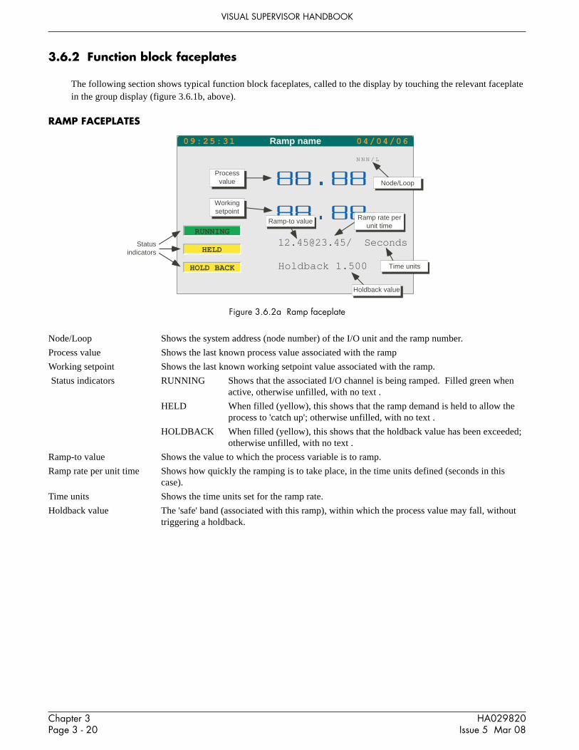
Chapter 3Page 3 - 20
HA029820Issue 5 Mar 08
VISUAL SUPERVISOR HANDBOOK
3.6.2 Function block faceplates
The following section shows typical function block faceplates, called to the display by touching the relevant faceplatein the group display (figure 3.6.1b, above).
RAMP FACEPLATES
Figure 3.6.2a Ramp faceplate
Node/Loop Shows the system address (node number) of the I/O unit and the ramp number.
Process value Shows the last known process value associated with the ramp
Working setpoint Shows the last known working setpoint value associated with the ramp.
Status indicators RUNNING Shows that the associated I/O channel is being ramped. Filled green whenactive, otherwise unfilled, with no text .
HELD When filled (yellow), this shows that the ramp demand is held to allow theprocess to 'catch up'; otherwise unfilled, with no text .
HOLDBACK When filled (yellow), this shows that the holdback value has been exceeded;otherwise unfilled, with no text .
Ramp-to value Shows the value to which the process variable is to ramp.
Ramp rate per unit time Shows how quickly the ramping is to take place, in the time units defined (seconds in thiscase).
Time units Shows the time units set for the ramp rate.
Holdback value The 'safe' band (associated with this ramp), within which the process value may fall, withouttriggering a holdback.
N N N / L
[email protected]/ Seconds
Holdback 1.500
Processvalue
Workingsetpoint
Node/Loop
Ramp rate perunit time
Ramp-to value
Time units
Holdback value
Statusindicators
RUNNING
HELD
HOLD BACK
09:25:31 Ramp name 04/04/06

Chapter 3Page 3 - 21
HA029280Issue 5 Mar 08
VISUAL SUPERVISOR HANDBOOK
3.6.2 FUNCTION BLOCK FACEPLATES (Cont.)
PID FACEPLATESDisplays a process style faceplate for PID, PID_LINK and PID_CONN function blocks.
Figure 3.6.2b PID faceplate
Process value Shows the last known process value associated with the loop
Working setpoint Shows the last known working setpoint value associated with the loop.
Local setpoint Shows the last known value for the local setpoint value associated with the loop.
Output percentage Shows the current percentage (0 to 100%) of full scale of the output.
Mode Shows the current mode (Auto, Manual or Remote).
Alarm The alarm beacon is red if the block is in alarm. The beacon is continuously red if the alarmhas been acknowledged, or flashes if unacknowledged.
Mode select These buttons allow the mode to be selected as ‘R’ (Remote), ‘A’ (Auto) or ‘M’ (Manual).
3.6.3 Display modes
Group data can be displayed in a number of formats, as listed below. When a group is touched, in the area display(section 3.6.1 above), it will appear in the format last used. Other modes are scrolled-to by means of the down arrowkey. The display modes are described below in the order in which they appear after a power up. This order is:1. User screen (if one has been set up) (not described here)2. Faceplate display3. Numeric4. Vertical bargraph5. Horizontal bargraph6. Vertical trend with point faceplates7. Vertical trend - full width - without faceplates8. Horizontal trend with point faceplates9. Horizontal trend - full width - without faceplates
Each of the above-mentioned displays supplies a real-time display of point data. By using the option key, then‘VIEW’, trend displays become trace-history displays. In such displays, real-time trending stops (although it is stillheld in the database for later display), and using various control sliders, the history of the traces can be displayed at aselectable magnification.
Mode select buttons
15:52:47 Loop name 04/04/06
R A M
100
0
PVSLSPOP
48.848.848.848.6
Eng
%
AUTO Alarms
Output
Local Setpoint
Working Setpoint
Process value
Mode
Working Setpoint
Process value
Down arrowkey
Option key

Chapter 3Page 3 - 22
HA029820Issue 5 Mar 08
VISUAL SUPERVISOR HANDBOOK
3.6.3 DISPLAY MODES (Cont.)
FACEPLATE DISPLAY
This display shows the contents of the group as what are called ‘faceplates’. This particular display is fully describedin the Overview (section 3.6.1 above). To scroll to the next display mode, touch the down arrow key.
PV1/1101
PV1/2680
PV2/1491
PV2/2671
PV3/1143
PV3/2193
09:54:17 04/04/06Name
PV1/1101
PV1/2680
PV2/1491
PV2/2671
PV3/1143
PV3/2193
10:03:34 04/04/06Name
04
00
08
00
08
00
08
00
04
00
04
00
09:21:13 This group 04/04/06
Ramp name Ramp name
Ramp name Ramp name
Ramp name Ramp name
Figure 3.6.3a Faceplate display mode
NUMERIC DISPLAYThis shows point values as seven segment displays, with faceplates.
Figure 3.6.3b Numeric display mode
VERTICAL BARGRAPHThis mode shows the current point values as vertical bars with faceplates. The height of each bar is proportional to thecurrent value of its associated point. Zero and full scale values appear to the left of the bars.
Figure 3.6.3c Vertical bargraph display mode

Chapter 3Page 3 - 23
HA029280Issue 5 Mar 08
VISUAL SUPERVISOR HANDBOOK
3.6.3 DISPLAY MODES (Cont.)
HORIZONTAL BARGRAPHThis mode shows the current point values as horizontal bars with faceplates. The length of each bar is proportional tothe current value of its associated point Zero and full scale values appear below the bars.
Figure 3.6.3d Horizontal bargraph display mode
VERTICAL TREND WITH FACEPLATE
Standard displayThis view displays points as though they are being traced on a chart which is rolling downwards. The latest data is atthe top of the display, and the extent of the data shown on the screen is displayed, at the bottom left of the screen, inhours and minutes.
For 1/4 VGA (XGA) displays Only the faceplates associated with the first six (16) group items can be displayed.Where there are more than six (16) trends, these are plotted without faceplate. As a part of the group’s configuration,it is possible to re-order the group contents to define which faceplates are displayed.
The colour bar at the top of each faceplate is that of its associated trend.
Scroll bar displayAn alternative view can be obtained by pressing the option key to display the options bar, then pressing ‘VIEW’. Thiscalls the scroll bar display shown in figure 3.6.3f below. If no further action is taken, trend data will continue to up-date normally.
PV1/1101
PV2/1491
PV2/2671
PV3/1143
PV3/2193
10:03:34 04/04/06Name
0 400
PV1/2680
0 800
0 800
0 800
0 400
0 800
07:56 00:00
SP 128.328.3
SP 242.2542.25
DSP 1NO DATA
DSP 2OPEN
DSP 3NO DATA
DSP 4OPEN
15:39:00 04/04/06spx7m
07:56
SP 128.328.3
SP 242.2542.25
DSP 1NO DATA
DSP 2OPEN
DSP 3NO DATA
DSP 4OPEN
15:41:17 04/04/06spx7m
00:00
Figure 3.6.3e Vertical trend with faceplates Figure 3.6.3f Vertical trend with scroll bars

Chapter 3Page 3 - 24
HA029820Issue 5 Mar 08
VISUAL SUPERVISOR HANDBOOK
3.6.3 DISPLAY MODES (Cont.)
VERTICAL TREND WITH FACEPLATE (Cont.)
Review modeIt is possible to enter review (trace history) mode bya. Touching the screen in either the Standard or the scroll bar displays described above or the full-width display
described below.b. Using the slider or push-button controls in the scroll bar displayc. Touching the slide area between the slider and a push button.
Although data is still read and stored in ‘trace history’ by the instrument, the traces remain static on the screen (unlessthe ‘zoom’ or ‘pan’ controls are used).
The Option/Live keys or the ‘Back Live’ key are used to return to the standard/scroll bar display
CURSOR On entry to review mode a cursor is located at the top of the screen. The cursor is repositioned either bytouching it and dragging it to the position required, or by touching the screen at the desired point (or acombination of both), The exact temporal position of the cursor is shown at the bottom of the screen, andthe values shown in the faceplates are those at the cursor time and date.
ZOOM These controls allow the amount of data displayed on the screen to be varied, either continuously, using theslider, or in steps (using the keys). The expansion/contraction of the trends is centred on the cursor position.
PAN These controls allow a particular section of the trend history to be selected for display. The length of thisdisplayed section is determined by the zoom setting.
Figure 3.6.3g Trend review controls
SP 128.328.3
SP 242.2542.25
DSP 1
DSP 2OPEN
DSP 3
DSP 4OPEN
15:41:17
04/04/06spx7m
Moving this (ZOOM) slider right(left) increases (decreases) theamount of time base displayed.Buttons have similar effect butprovide step changes. Zoomfactor is shown below the display.
Use this (PAN) slider (or thearrow keys) to select that part of
the time base to be viewed.(Down moves back in time.)
17/02/02 13:31:17 (x2)
Cursor (initially attop edge of screen)
Faceplatevalues arethose at thecursor timeand date.
Cursor date Cursor time Zoomfactor ‘Back Live’ key
27.3528.05
48.7548.55

Chapter 3Page 3 - 25
HA029280Issue 5 Mar 08
VISUAL SUPERVISOR HANDBOOK
3.6.3 DISPLAY MODES (Cont.)
VERTICAL TREND - FULL WIDTHThis view fills the width of the screen, with no faceplates displayed. Review mode is as described above.
Figure 3.6.3h Vertical full width display mode
HORIZONTAL TREND WITH FACEPLATEThe horizontal trend displays are similar to the vertical trend displays. The main difference (apart from the length ofdata displayed and that the traces move from right to left) is the swapping of the Pan and Zoom control locations inTrend review mode.
Latest data is the right hand edge of the screen
Figure 3.6.3i Horizontal trend with faceplates
03:85
13:55:19 04/04/06spx7m
00:00
07:56 00:00
15:35:51 04/04/06spx7mSP 1
28.328.3
SP 242.2542.25
DSP 1
DSP 2OPEN
DSP 3
DSP 4CLOSED
27.3528.05
48.7548.55

Chapter 3Page 3 - 26
HA029820Issue 5 Mar 08
VISUAL SUPERVISOR HANDBOOK
3.6.3 DISPLAY MODES (Cont.)
HORIZONTAL TREND WITH FACEPLATE (Cont.)
Review modeThe section describing ‘Vertical trend with faceplate’, above, gives full details of review mode.The Cursor appears at the right hand edge of the screen for horizontal traces.
17/02/02 13:31:17 (x2)
13:29:07 04/04/06spx7m
Moving this (zoom) slider down(up) increases (decreases) theamount of time base displayed.Buttons have similar effect butprovide step changes. Zoomfactor is shown below the display.
Cursor (initially atright edge of screen)
Faceplatevalues arethose at thecursor timeand date.
Cursor date Cursor time Zoomfactor
Use this (pan) slider (or thearrow keys) to select that part of
the time base to be viewed.(Left moves back in time.)
'Back Live’ key
SP 128.328.3
SP 242.2542.25
DSP 1
DSP 2OPEN
DSP 3
DSP 4OPEN
27.3528.05
48.7548.55
05:14
13:50:43 04/04/06spx7m
00:00
Figure 3.6.3j Trend review controls
HORIZONTAL TREND - FULL WIDTH
Figure 3.6.3k Horizontal full width

Chapter 3Page 3 - 27
HA029280Issue 5 Mar 08
VISUAL SUPERVISOR HANDBOOK
3.7 DOWNLOADING RECIPES
A recipe set consists of sets of instructions (recipes) for controlling between one and eight identical production facili-ties. The examples below use paint mixers as an illustration of the four types of recipe available.1. The simple recipe. This file contains references to a single set of equipment and a single set of values to be ap-
plied to the equipment (e.g. orange paint)2. The multi-recipe. This file contains references to a single set of equipment and multiple sets of values to be ap-
plied to that equipment (e.g. orange, purple and brown paint.)3. A multi-line recipe. This file contains a single set of values that may be applied, simultaneously, to up to four
sets of equipment (e.g. orange paint to line 1, orange paint to line 2, orange paint to line 3.)4. A multi-line, multi-recipe. This file contains multiple values that may be applied, simultaneously, to up to four
sets of equipment. (e.g. orange paint to line 1, purple paint to line 2, brown paint to line 3, green paint to line 4.)
Figure 3.7a shows a simplistic view of example 4, and figure 3.7b, a sample recipe page.
Notes:1 In cases 1 and 2 above, there is only a single line, so references to ‘lines’ do not appear in the user
interface.2 The number of recipe files that can be loaded simultaneously depends on the application. The number of
files that can be loaded is defined by the number of sets (each with a separate ID). If only one set or ID isconfigured, then references to set IDs do not appear at the user interface.
PAINT09:12:21 04/04/06RCP Purple
red pigmentblue pigmentyellow pigment
50.0
50.0
0.050.0
0.0
50.035.0
30.0
35.0
Recipe set file name
Orange Brown
Recipe names
Variablenames
Variablevalues
Yellow Pigment
Red Pigment
Blue Pigment
OrangeRecipe
Line 2
PurpleRecipe
BrownRecipe
Paint maker recipe set (any line can make any colour)
Co
ntr
ol
Sig
na
ls
OrangeRecipe
Line 4
PurpleRecipe
BrownRecipe
GreenRecipe
OrangeRecipe
Line 3
PurpleRecipe
BrownRecipe
Orangepaint
Purplepaint
Brownpaint
Greenpaint
Mixer 4Mixer 2 Mixer 3Mixer 1
Co
ntr
ol
Sig
na
ls
Co
ntr
ol
Sig
na
ls
Co
ntr
ol
Sig
na
ls
GreenRecipe
GreenRecipe
OrangeRecipe
Line 1
PurpleRecipe
BrownRecipe
GreenRecipe
Figure 3.7a Four paint-mixer set
Figure 3.7b Sample recipe edit page

Chapter 3Page 3 - 28
HA029820Issue 5 Mar 08
VISUAL SUPERVISOR HANDBOOK
3.7.1 Download procedure
1. Select a recipe set ID (only if multiple recipe sets are supported).2. Load a recipe file3. Select a recipe line (only if multiple lines are supported)4. Select a recipe (only if the file contains multiple recipes)5. Download the recipe.
RECIPE SET SELECTION
1 From the main menu, select RECIPE
2 From the resulting pop-up menu, select RECIPES
3. The Recipe Load/Save page appears with the recipe setID and name of any currently loaded recipe file, or, ifnone, lines of question marks.
To select a new set or recipe file, touch the ID orFilename area and select the required item from thepicklist which then appears. Alternatively, the variousavailable selections can be scrolled through, using theleft/right arrow keys at the bottom of the display.
EDIT DOWNLOAD ABORT
RECIPES STATUS MONITOR
Recipe
ACCESS
OVERVIEW
LOGGING
SYSTEM
PROGRAMMER
HOME
ALARMS
RECIPE
Figure 3.7.1a Main menu
Figure 3.7.1b Recipe menu
LOADING THE RECIPEOnce the required file has been selected, operation of the load button will call the recipe menu (figure 3.7.1b). Therecipe can now be loaded by operation of the DOWNLOAD key. If, however, it is necessary to select a particularrecipe line, or if it is necessary to select one recipe from a number in the file, the STATUS button should be operatedto display the Recipe Status page.
Note: The contents of the status page is context dependent, so it is unlikely that it will contain exactly thesame fields as shown in the figures below.
Load/Save Recipe 04/04/06
Id:File name:
15:18:42
LOAD
????????????????

Chapter 3Page 3 - 29
HA029280Issue 5 Mar 08
VISUAL SUPERVISOR HANDBOOK
3.7 DOWNLOADING RECIPES (Cont.)
SELECTING A RECIPE LINEIf more than one line is present in a recipe set, it is possibleto select which is to be the current line to which the recipeis to be down loaded. With the Recipe Status page dis-played, (figure 3.7.1d), touch the yellowed Line field andselect a new line from the resulting pick list. Alternatively,the down-arrow key at the bottom of the screen can beused to scroll through the available items. The file cannow be downloaded by pressing the DOWNLOAD key.
SELECTING A RECIPEIf more than one recipe is present in a file, then it is possi-ble to select which recipe is to be the current one. With theRecipe Status page selected (figure 3.7.1e), a touch on therecipe field will call a pick list from which the requireditem can be selected. The recipe can now be downloadedusing the DOWNLOAD key.
Recipe Status 04/04/0616:16:37
Id:File name:
Line:Recipe Name:
ABORTDOWNLOAD
`
SET 1RECIPESLine 2Run Prog
Recipe Status 04/04/0616:27:56
Id:File name:
Recipe Name:
ABORTDOWNLOAD
`
GasMixesGASCONCAmarillo
Figure 3.7.1d Status page for multi-line recipes
Figure 3.7.1e Status page for recipe selection
3.7.2 Monitoring the recipe
A recipe can be monitored from the Recipe Status screen, and from the Recipe Monitor screen.
RECIPE STATUS PAGEThe recipe status screen contains the File name and the Recipe name, and any one or more of the following fields:Set IDLineStatus (if downloaded)*Time/date of last download
* Status can be any one of the following:DOWNLOADING - if a download is in progressCOMPLETE - if the latest download was completed successfullyFAILED - if the previous download was unsuccessful or aborted.

Chapter 3Page 3 - 30
HA029820Issue 5 Mar 08
VISUAL SUPERVISOR HANDBOOK
3.7.2 MONITORING THE RECIPE (Cont.)
RECIPE MONITOR PAGEThis page is called from the Recipe menu (figure 3.7.1b) by touching the MONITOR key. The monitor page givesrecipe values in tabular form as shown below.
As can be seen, the following columns are displayed:
RCP The recipe variablesSP The value held in the recipe file for each variable.SP (Live) The current live database values for each variable. Where the SP and SP(Live) values differ, the value is
highlighted in red, providing a useful diagnostic should a recipe download fail.PV Optional values monitored in conjunction with the recipe. Might not be present on any recipe file.Capture Optional values that would be captured if a recipe CAPTURE is performed. Might not be present on any
recipe file.
Figure 3.7.2 Recipe monitor page (XGA version)
Note: For 1/4VGA units, the capture column is initially hidden, the scroll bar below the table allowing it tobe viewed. This scroll bar and the SAVE/CAPTURE keys (shown above) are toggled between by means ofthe options key.
3/5TRENDRUNNING 05:07:45 2
Run progTREND
Fred
Gas Mix
SP SP (Live) PV CAPTURERCPMethaneNitrogenCarbon Dioxide
Ethane
PropaneWaterHydrogenSulphideHydrogen
Carbon MonoxideOxygeni Butane
n Butanei Pentane
n Pentanen Hexane
n Heptanen Octanen Nonanen DecaneHelium
90.67243.12840.4676
4.5279
0.8280.00.00.0
0.00.0
0.1037
0.15630.0321
0.04430.0393
0.00.00.00.00.0
90.67243.12840.4676
4.5279
0.82800.00000.00000.0000
0.00000.00000.1037
0.15630.0321
0.04430.0393
0.00000.00000.00000.00000.0000
90.67243.12840.4676
4.5279
0.82800.00000.00000.0000
0.00000.00000.1037
0.15630.0321
0.04430.0393
0.00000.00000.00000.00000.0000
90.67243.12840.4676
4.5279
0.82800.00000.00000.0000
0.00000.00000.1037
0.15630.0321
0.04430.0393
0.00000.00000.00000.00000.0000
SAVE CAPTURE CAPTURE AS DOWNLOAD ABORT
F1 F2 F3
F10 F11 F12
F4 F5 F6 F7 F8 F9
F13 F14 F15 F16 F17 F18
F19 F20 F21 F22 F23 F24 F25 F26 F27

Chapter 3Page 3 - 31
HA029280Issue 5 Mar 08
VISUAL SUPERVISOR HANDBOOK
3.8 BATCHES
3.8.1 Batch loading
1 From the main menu, select BATCH, then select BATCHES
2 Touch the ID or filename area
3 Select the required item from the picklist which appears.
4 Operate the LOAD button.
Note: For the ‘Create’ function, see section 3.8.8, below.
ACCESS SYSTEM ALARMS
OVERVIEW PROGRAMMER RECIPE
BATCH LOGGING HOME
NOTE
STATUS
HOLD
RESET ABORT
RESTART
BATCHES
Batch
Load Batch 04/04/0612:35:33
File Name:
LOAD CREATE
0/0SAMPLERUNNING 13:06:34 1
????????
Batch Start 04/04/0612:35:33
File Name:Batch Id:Order No:Customer:Contact:
SAVE AS
0/0SAMPLERUNNING 13:06:34 1
START RESET
BATCH50462977<Order number><Company><Contact name>
3.8.2 Recipe selection
If applicable, a specific recipe can be selected for loading, from a pick list which appears if the Recipe field area istouched.
3.8.3 Batch customising
The Batch ID is initially chosen as unique by the instrument. The name can be edited in the normal way. In additionto the batch ID there can be up to six custom items (in the example shown there are three, viz: Order No, Customerand Contact). Again, these items are editable in the normal way. The titles of these custom items (e.g. Order No.) areset up using the customising techniques described in Chapter 5, below.

Chapter 3Page 3 - 32
HA029820Issue 5 Mar 08
VISUAL SUPERVISOR HANDBOOK
Please confirm starting of batch
Batch Start Confirm
OK CANCEL
Please confirm your password to
start batch.
Password:
Batch Start Confirm
********
OK CANCEL
3.8.4 Batch initiation
Once all the batch data has been entered, operation of the START key causesone of the following to occur, depending on the way in which the batch hasbeen configured:1 The batch starts immediately2 A dialogue box appears asking for confirmation of Batch Start. Opera-
tion of the OK button starts the batch.3 A dialogue box appears asking for the current user’s password. Entry of
the password followed by operation of the OK button starts the batch.
3.8.5 Batch monitoring
The batch may be monitored from the Batch Status screen which is accessed from the main menu using the BATCHkey, then the STATUS key.
The batch status screen contains all the information present on the Batch Start screen, but also includes the State ofthe batch, its ‘Started at’ and (if appropriate) ‘Ended at’ time and date, and phase information. If a batch message isactive, an annunciator bar appears near the top of the page flashing orange/black and a question mark with orange/black flashing background appears at the left side of the alarm pane. Touching the alarm pane allows review and ac-knowledgement of the message.
Batch Status 05/04/0612:35:19
File Name:
Recipe Name:
Batch Id:
Order No:
Customer:
Contact:
State:
Started At:
Ended At:
HOLD
0/0SAMPLERUNNING 13:06:34 1
Batch Message
BATCH
1
50562985
060405
FishesRus
C. BASS
COMPLETE
05/04/06 12:30:46
05/05/06 12:34:43
RESTART ABORT RESET
Batch messageannunciator
Figure 3.8.5 Batch status page
3.8.6 Batch Hold
With a batch running, operating the HOLD key from either the BATCH menu or the Batch Status screen, places thebatch into hold mode. The batch may be restarted as required, by pressing ‘RESTART’.
3.8.7 Batch Abort
With a batch running or held, operating the ABORT key from either the BATCH menu or the Batch Status screen,immediately terminates the batch.

Chapter 3Page 3 - 33
HA029280Issue 5 Mar 08
VISUAL SUPERVISOR HANDBOOK
3.8.8 Batch Create
A new batch can be created by operating the CREATE key from the ‘Load batch’ page described in section 3.8.1,above.
Operation of the CREATE key causes a pick list to appear allowing the user to define batch parameters, as shown inthe figure.
CREATE AS ..Filename:
Recipe Line:Display Group:
Message:Log Group:
Log Report:
<NONE><NONE><NONE><NONE><NONE>
OK CANCEL
Filename* Allows a filename (eight characters max.) to be entered for the Batch file.
Recipe line Allows a recipe line to be chosen for batch action.
Display Group Allows one of the display groups to be selected for batch action - see section 3.6 for further details
Message Allows a message (set up in LIN blocks configuration) to be selected for display as appropriate.
Log Group Allows a log group to be selected for Batch action (section 4.2).
Log Report A logging group may have been configured to have "reports". In such a case, one of the log group’sreport files may be selected to drive batch reports. A batch report is generated for start, stop andabort. The create facility generates an elementary report file (.UYF) which may be customised bybeing exported and edited (see section 5.9.1 for further details of .UYF files).
* Entry of a Filename is mandatory. Other field entries are optional.

Chapter 3Page 3 - 34
HA029820Issue 5 Mar 08
VISUAL SUPERVISOR HANDBOOK
This page is deliberately left blank
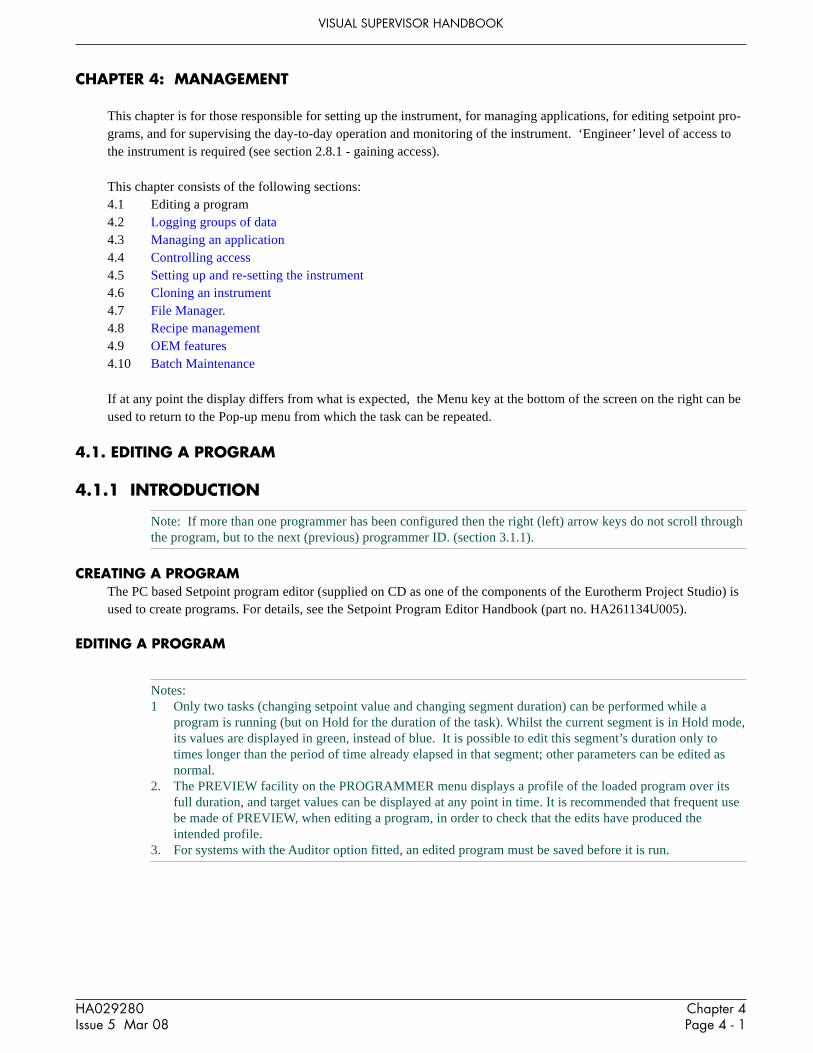
Chapter 4Page 4 - 1
HA029280Issue 5 Mar 08
VISUAL SUPERVISOR HANDBOOK
CHAPTER 4: MANAGEMENT
This chapter is for those responsible for setting up the instrument, for managing applications, for editing setpoint pro-grams, and for supervising the day-to-day operation and monitoring of the instrument. ‘Engineer’ level of access tothe instrument is required (see section 2.8.1 - gaining access).
This chapter consists of the following sections:4.1 Editing a program4.2 Logging groups of data4.3 Managing an application4.4 Controlling access4.5 Setting up and re-setting the instrument4.6 Cloning an instrument4.7 File Manager.4.8 Recipe management4.9 OEM features4.10 Batch Maintenance
If at any point the display differs from what is expected, the Menu key at the bottom of the screen on the right can beused to return to the Pop-up menu from which the task can be repeated.
4.1. EDITING A PROGRAM
4.1.1 INTRODUCTION
Note: If more than one programmer has been configured then the right (left) arrow keys do not scroll throughthe program, but to the next (previous) programmer ID. (section 3.1.1).
CREATING A PROGRAMThe PC based Setpoint program editor (supplied on CD as one of the components of the Eurotherm Project Studio) isused to create programs. For details, see the Setpoint Program Editor Handbook (part no. HA261134U005).
EDITING A PROGRAM
Notes:1 Only two tasks (changing setpoint value and changing segment duration) can be performed while a
program is running (but on Hold for the duration of the task). Whilst the current segment is in Hold mode,its values are displayed in green, instead of blue. It is possible to edit this segment’s duration only totimes longer than the period of time already elapsed in that segment; other parameters can be edited asnormal.
2. The PREVIEW facility on the PROGRAMMER menu displays a profile of the loaded program over itsfull duration, and target values can be displayed at any point in time. It is recommended that frequent usebe made of PREVIEW, when editing a program, in order to check that the edits have produced theintended profile.
3. For systems with the Auditor option fitted, an edited program must be saved before it is run.

Chapter 4Page 4 - 2
HA029280Issue 5 Mar 08
VISUAL SUPERVISOR HANDBOOK
EDITING A PROGRAM (Cont.)
Before editing can start, the Program Editor page must be accessed as described in section 4.1.2. Once the editor pagehas been accessed, the program can be edited in the following ways:
Changing a setpoint (section 4.1.3)By changing the type of ramp to itBy changing its value
Changing a segment (section 4.1.4)By changing its identifierBy changing its duration
Inserting or deleting a segment (section 4.1.5)Inserting a segmentDeleting a segment
Changing the Hold Back properties for any analogue setpoint (section 4.1.6)Choosing the setpointChanging the Holdback modeChanging the Holdback value
Changing program properties (section 4.1.7)Changing the name of a programChanging the rate units for a programChoosing an action to be taken at the end of each run

Chapter 4Page 4 - 3
HA029280Issue 5 Mar 08
VISUAL SUPERVISOR HANDBOOK
ACCESS
PROGRAMMER
SYSTEM ALARMS
OVERVIEW
2Press Programmer key
LOGGING
1Press menu key
4.1.2 Program Editor Page access
1. Press the Menu key, then PROGRAMMER
The Programmer menu appears.
2. Press PROGRAMS
The Load/Save Program page appears, prompting you for the nameof a file to Load or Save. (To edit a program, it must first be loaded.)
3. Press the File Name field (the question marks).
On the left of the screen, a pick-list appears, containing the programsheld by the instrument.
4. Press the name of the program to be edited
5. Press the green Return key
The Load/Save program page displays the name of the selected pro-gram.
6. Press LOAD.
If the program has components (parameters) which are not in the LINdatabase then an error message will appear and the program will notload.
After a successful load, the Programmer menu reappears.
7. Press EDIT
The Program Editor page appears showing the values of the setpointsin tabular form.
Each row represents one setpoint along a horizontal timebase markedin segments. Some of the rows are for analog setpoints and some arefor digital ones.
Each column represents a segment, and each segment is identified bya name or number shown at the top of the column. Under the seg-ment identifier is the time duration of the segment.
All the yellowed fields yield further information when pressed.
Programmer
RUN
RUN FROM
PREVIEW
MONITOR PROGRAMS
PRE-PLOT
HOLD
SKIP
ABORT
EDIT
SCHEDULE
Load/Save program 05/04/06
File Name:
08:31:03
????????
LOAD SAVE SAVE AS DELETE
LOAD
Load/Save program 05/04/0608:31:49
????????
SAVE AS DELETE
File Name:dsampleSTMAXALLENMAXSEGENMAXSPSAMPLE
????????File Name:
LOADLOAD
Load/Save program 05/04/06
File Name:
08:31:15
SAMPLE
LOAD SAVE SAVE AS DELETE
Load/Save program 05/04/06
File Name:
08:31:23
SAMPLE
LOAD SAVE SAVE AS DELETE
Programmer
RUN
RUN FROM
PREVIEW
MONITOR PROGRAMS
PRE-PLOT
HOLD
SKIP
ABORT
EDIT
SCHEDULE
SAMPLE 05/04/0608:31:49
SP
Ana In 1
Ana In 2
Ana In 3
Dig in 1
Dig in 2
Dig in 3
100:05:00
200:50:00
300:35:00Rto 0.0
Rto 100.0
Sto 50.0
Rto 20.0
Rto 65.0
Sto 50.0
Rto 97.7
Rto 99.0
Sto 50.0
OPEN CLOSED
CLOSED OPEN
OPEN CLOSED
OPEN
CLOSED
OPEN

Chapter 4Page 4 - 4
HA029280Issue 5 Mar 08
VISUAL SUPERVISOR HANDBOOK
4.1.3 Changing a setpoint
CHANGING RAMP TYPE
Generally there are up to six ways in which you can program the Visual Supervisor to control the value of a setpoint(some may not be available on your instrument). These methods are called ‘Step’ (sometimes called ‘Set’), ‘Dwell’,‘Ramp at’. Ramp to’, ‘Servo to setpoint’ and ‘Servo to process variable’.
StepValue changes instantaneously. Can be used in any segment. Also called ‘Set’.
DwellValue remains constant. May be used in all segments except the first.
Ramp atValue increases at a constant specified rate. May be used in all segments except the first.
Ramp toValue increases linearly to a specified value
Notes:1. ‘Ramp at’ and ‘Ramp to’ cannot be mixed within the same segment. If an attempt is made to change one
of the SPs from one type to the other, a message appears warning that all the other similar types in thatsegment will be changed to conform.
2. A segment may not ramp at less than 0.001 or greater than 9999.0 whether expressed explicitly in a‘Ramp At’ command, or implicitly in a ‘Ramp to’ command. Values outside this range cause the segmentto execute a ‘step’ function.
Servo to setpoint (SP)The unit reads the current setpoint value, and sets the setpoint to that value (that is, it does not change it). Similar to‘Dwell’ except that the instrument carries out the instruction automatically (without operator intervention). As there isno change, power output remains constant. May be used only in the first segment.
Servo to process variable (PV)The instrument reads the current process value and sets the setpoint to that value. Because the current process valuenormally differs from the current setpoint value, this option usually results in a change in the power consumption ofthe process.
Note: If the first segment is a Servo to PV or SP, the instrument assumes that it starts from an SP of 0.0. Thisis unlikely to be the actual SP or PV. Therefore the Preview profile displayed for the first segment will differfrom the actual programmed profile. For the same reason, if the second segment is a ramp-at-rate, the segmentduration in Preview will differ from the actual duration; and if the second segment is ramp-to-target then theslope in Preview will differ from the actual slope.
TERMINOLOGYIn this document any change in the value of the setpoint is referred to as a ‘ramp’, even when the result of that changeis zero. This means that the six methods of controlling the value of the setpoint, described above, all result in types oframp.

Chapter 4Page 4 - 5
HA029280Issue 5 Mar 08
VISUAL SUPERVISOR HANDBOOK
4.1.3 CHANGING A SETPOINT (Cont.)
TO CHANGE THE TYPE OF RAMPExample for Analog Input 1: The following example describes how tochange the ramp in Segment 2 from a ‘time-to-target’ to a ‘ramp-to-tar-get’.
In the Program Editor page, the cell for Analog Input 1, Segment 2shows R for ‘Ramp’ and ‘to 100.0’ for the value, indicating that it iscurrently a ramp to a specified value.
Press the cell.A dialogue box appears displaying data about that cell.
Press the yellowed ‘Ramp’ field.
A pick-list of ramp types appears, with ‘Ramp’ highlighted
Press the required type (in this case, ‘Ramp@’).
‘Ramp@’ highlights yellow.
Press the green ‘Return’ key.
The dialogue box reappears, now showing ‘Ramp@’ in the ‘Type’ field,followed by an extra field ‘Ramp at’. (This field appears only whenchanging to a ‘Ramp@’).
Press the yellowed ‘Ramp at’ field, currently showing 0.0/m (standingfor zero units per minute).
SAMPLE 05/04/0608:35:13
SP
Ana In 1
Ana In 2
Ana In 3
Dig in 1
Dig in 2
Dig in 3
100:05:00
200:50:00
300:35:00Rto 0.0
Sto 50.0
Rto 20.0
Rto 65.0
Sto 50.0
Rto 97.7
Rto 99.0
Sto 50.0
OPEN CLOSED
CLOSED OPEN
OPEN CLOSED
OPEN
CLOSED
OPEN
Rto 100.0
Segment:Setpoint:
Type:Ramp at:
to:
DONE
2Ana In 1Ramp@ 0.0/m100.0
SAMPLE 05/04/0608:33:15
SP
Ana In 1
Ana In 2
Ana In 3
Dig in 1
Dig in 2
Dig in 3
100:05:00
200:50:00
300:35:00Rto 0.0
Sto 50.0
Rto 20.0
Rto 65.0
Sto 50.0
Rto 97.7
Rto 99.0
Sto 50.0
OPEN CLOSED
CLOSED OPEN
OPEN CLOSED
OPEN
CLOSED
OPEN
Rto 100.0Segment:
Setpoint:Type:
to:
2Ana In 1Ramp100.0
DONE
SAMPLE 05/04/0608:33:49
SP
Ana In 1
Ana In 2
Ana In 3
Dig in 1
Dig in 2
Dig in 3
100:05:00
200:50:00
300:35:00Rto 0.0
Sto 50.0
Rto 20.0
Rto 65.0
Sto 50.0
Rto 97.7
Rto 99.0
Sto 50.0
OPEN CLOSED
CLOSED OPEN
OPEN CLOSED
OPEN
CLOSED
OPEN
Rto 100.0Segment:
Setpoint:Type:
to:
2Ana In 1Ramp100.0
DONE
Step
Ramp@
Ramp
Dig in
SP
Ana In 1
00:05:00 0S RSegment: 2
Dig in 2
Di i 3
CLOSED O
OPEN C
DON
Dwell
Ramp
SAMPLE 05/04/0608:34:08
SP
Ana In 1
Ana In 2
Ana In 3
Dig in 1
Dig in 2
Dig in 3
100:05:00
200:50:00
300:35:00Rto 0.0
Sto 50.0
Rto 20.0
Rto 65.0
Sto 50.0
Rto 97.7
Rto 99.0
Sto 50.0
OPEN CLOSED
CLOSED OPEN
OPEN CLOSED
OPEN
CLOSED
OPEN
Rto 100.0Segment:
Setpoint:Type:
to:
2Ana In 1Ramp100.0
DONE
Step
Ramp@
Dig in
SP
Ana In 1
00:05:00 0S RSegment: 2
p
Dig in 2
Di i 3
CLOSED O
OPEN C
DON
Dwell
Ramp@Ramp
SAMPLE 05/04/0608:31:49
SP
Ana In 1
Ana In 2
Ana In 3
Dig in 1
Dig in 2
Dig in 3
100:05:00
200:50:00
300:35:00Rto 0.0
Rto 100.0
Sto 50.0
Rto 20.0
Rto 65.0
Sto 50.0
Rto 97.7
Rto 99.0
Sto 50.0
OPEN CLOSED
CLOSED OPEN
OPEN CLOSED
OPEN
CLOSED
OPEN

Chapter 4Page 4 - 6
HA029280Issue 5 Mar 08
VISUAL SUPERVISOR HANDBOOK
4.1.3 CHANGING A SETPOINT (Cont.)
TO CHANGE THE TYPE OF RAMP (Cont.)
A numeric keyboard is displayed, showing the current value of the ramp ina black confirmation bar at the top.
Key in the required ramp rate. As soon as the first digit is entered, the restof the bar clears.
When the new entry is complete, press Return.The dialogue box reappears, displaying the new value for the ramp rate.
Press DONE.
A new ‘Ramp to’ value is shown in the cell. To save the new ramp type,press the Option key at the bottom of the screen, then press the SAVE but-ton that appears on a bar at the bottom of the screen.
CHANGING SETPOINT VALUE
In the Program Editor page, select the analogue cell holding the value to bechanged.A dialogue box appears, showing:1 the segment name or number2 the setpoint name for that row3 the setpoint type4 the current target value for the setpoint in that cell.
To change the target value, touch the value and enter the new value usingthe keyboard display which appears.
Press the Return key
The dialogue box reappears, this time showing the new value.
Press DONE
The Program Editor page returns, with the new value shown in the selectedcell.
To save the setting, press the Option key (below the screen), and then theSAVE button.
SAMPLE 05/04/06
SP
Ana In 1
Ana In 2
Ana In 3
Dig in 1
Dig in 2
Dig in 3
100:05:00
200:50:00
300:35:00Rto 0.0
Sto 50.0
Rto 20.0
Rto 65.0
Sto 50.0
Rto 97.7
Rto 99.0
Sto 50.0
OPEN CLOSED
CLOSED OPEN
OPEN CLOSED
OPEN
CLOSED
OPEN
Rto 100.0
08:35:45
Segment:Setpoint:
Type:Ramp at:
to:
DONE
2Ana In 1Ramp@ 0.0/m100.0
0.0008 97
5 64
1 2 3
. 0Dig i
SAMPLE 05/04/06
SP
Ana In 1
Ana In 2
Ana In 3
Dig in 1
Dig in 2
Dig in 3
100:05:00
200:50:00
300:35:00Rto 0.0
Sto 50.0
Rto 20.0
Rto 65.0
Sto 50.0
Rto 97.7
Rto 99.0
Sto 50.0
OPEN CLOSED
CLOSED OPEN
OPEN CLOSED
OPEN
CLOSED
OPEN
Rto 100.0
08:36:23
Segment:Setpoint:
Type:Ramp at:
to:
DONE
2Ana In 1Ramp@ 1.0/m100.0
SAMPLE 05/04/06
SP
Ana In 1
Ana In 2
Ana In 3
Dig in 1
Dig in 2
Dig in 3
100:05:00
1a00:00:00
200:50:00
Sto 50.0
Rto 65.0
Rto 65.0
Sto 50.0
Rto 99.0
Rto 99.0
Sto 50.0
OPEN CLOSED
CLOSED OPEN
OPEN CLOSED
OPEN
CLOSED
OPEN
Rto 100.0
Rto 00.0
08:43:34
Segment:Setpoint:
Type:to:
1Ana In 1Step50.0
DONE
SAMPLE 05/04/06
SP
Ana In 1
Ana In 2
Ana In 3
Dig in 1
Dig in 2
Dig in 3
100:05:00
1a00:00:00
200:50:00Rto 0.0
Sto 50.0
Rto 65.0
Rto 65.0
Sto 50.0
Rto 99.0
Rto 99.0
Sto 50.0
OPEN CLOSED
CLOSED OPEN
OPEN CLOSED
OPEN
CLOSED
OPEN
Rto 100.0Segment:
Setpoint:Type:
to:
1Ana In 1Step50.0
DONE
08:43:48
8 97
5 64
1 2 3
. 0Dig i
50.00
SAMPLE 05/04/06
SP
Ana In 1
Ana In 2
Ana In 3
Dig in 1
Dig in 2
Dig in 3
100:05:00
1a00:00:00
200:50:00
Sto 50.0
Rto 65.0
Rto 65.0
Sto 50.0
Rto 99.0
Rto 99.0
Sto 50.0
OPEN CLOSED
CLOSED OPEN
OPEN CLOSED
OPEN
CLOSED
OPEN
Rto 100.0
Rto 00.0
08:43:56
Segment:Setpoint:
Type:to:
1Ana In 1Step60.0
DONE
SAMPLE 05/04/06
SP
Ana In 1
Ana In 2
Ana In 3
Dig in 1
Dig in 2
Dig in 3
100:05:00
1a00:00:00
200:50:00
Sto 60.0
Rto 65.0
Sto 50.0
Rto 99.0
Sto 50.0
OPEN CLOSED
CLOSED OPEN
OPEN CLOSED
OPEN
CLOSED
OPEN
Rto 100.0
08:44:23
D
D
D
Option key

Chapter 4Page 4 - 7
HA029280Issue 5 Mar 08
VISUAL SUPERVISOR HANDBOOK
4.1.4 Changing a segment
In the Program Editor page, press the identifier at the top of the column ofthe segment to be modified. For example, segment 1.
A dialogue box appears with two fields: Segment and Duration, and threebuttons: INS SEG, DEL SEG and DONE.
The following subsections show how to change a segment’s identifier andduration respectively. Inserting and deleting segments is described in sec-tion 4.1.5.
Once the segment changes are complete, the SAVE button is used to savethe changes. If necessary, the SAVE button is called to the display bypressing the ‘option’ key located below the screen.
CHANGING SEGMENT IDENTIFIER
In the dialogue box, press the Segment field.
A ‘qwerty’ keyboard appears.
A numeric/symbol keyboard can be called by pressing the ‘up arrow’ keyat bottom left. A further operation of the arrow key calls a keyboard ofaccented lower-case letters. Pressing the up arrow key again re-displaysthe original ‘qwerty’ keyboard.
The segment identifier can be a name, a number, a character or a digit, butDOS file name rules apply.
The required segment identifier (for example, ‘a’) is keyed-in using one ormore of these keyboards.
To clear the entry so far (but retaining the keyboard display), press the ‘C’key.
To cancel the entry and return to the setpoint display, press the red crosskey.
Once the segment identifier has been keyed in, the Return key is operatedto save it.
The Program Editor page reappears, showing the new identifier for thesegment.
Option key
SAMPLE 05/04/0608:46:49
SP
Ana In 1
Ana In 2
Ana In 3
Dig in 1
Dig in 2
Dig in 3
200:50:00
300:35:00Rto 0.0
Sto 50.0
Rto 20.0
Rto 65.0
Sto 50.0
Rto 97.7
Rto 99.0
Sto 50.0
OPEN CLOSED
CLOSED OPEN
OPEN CLOSED
OPEN
CLOSED
OPEN
Rto 100.0
100:05:00
Segment:Duration:
DEL SEG DONEINS SEG
100:05:00
1
q w e r t y u i o p
a s d f g h j k l ;
z x c v b n m ,
04/04/0608:44:03 S A M P L E
SP
Ana In 1
Ana In 2
Ana In 3
Dig in 1
Dig in 2
Dig in 3
200:50:00
300:35:00Rto 0.0
Sto 50.0
Rto 20.0
Rto 65.0
Sto 50.0
Rto 97.7
Rto 99.0
Sto 50.0
OPEN CLOSED
CLOSED OPEN
OPEN CLOSED
OPEN
CLOSED
OPEN
Rto 100.0
a00:05:00
SAMPLE 05/04/0608:44:23

Chapter 4Page 4 - 8
HA029280Issue 5 Mar 08
VISUAL SUPERVISOR HANDBOOK
4.1.4 CHANGING A SEGMENT (Cont.)
CHANGING SEGMENT DURATION
Caution:1. Changing the duration of ‘ramp-at-rate’ segments is not permitted.2. Changing the duration of ‘ramp-to’ segments changes the rate of ramp. Therefore, before making any
such change, you should consider the possible ef fect of this upon the operation of the process plant.
SAMPLE 05/04/0609:01:37
SP
Ana In 1
Ana In 2
Ana In 3
Dig in 1
Dig in 2
Dig in 3
200:50:00
300:35:00Rto 0.0
Sto 50.0
Rto 20.0
Rto 65.0
Sto 50.0
Rto 97.7
Rto 99.0
Sto 50.0
OPEN CLOSED
CLOSED OPEN
OPEN CLOSED
OPEN
CLOSED
OPEN
Rto 100.0
100:05:00
Segment:Duration:
DEL SEG DONEINS SEG
100:05:00
00:05:008 97
5 64
1 2 3
. 0Dig i
SAMPLE 05/04/0609:02:09
SP
Ana In 1
Ana In 2
Ana In 3
Dig in 1
Dig in 2
Dig in 3
200:50:00
300:35:00Rto 0.0
Sto 50.0
Rto 20.0
Rto 65.0
Sto 50.0
Rto 97.7
Rto 99.0
Sto 50.0
OPEN CLOSED
CLOSED OPEN
OPEN CLOSED
OPEN
CLOSED
OPEN
Rto 100.0
100:06:00
In the dialogue box, press the Duration field.
A numeric keyboard appears, with the current duration displayed at the topin hh:mm:ss format. The format can be changed, as described in section4.5.4 Changing the language and date formats.
Key-in the required duration.
Once the correct duration is keyed-in, the Return key is used to save it.
The Program Editor page appears, showing the new duration for the seg-ment.
Note: Neither an individual segment duration nor the total programduration may exceed 49 days.
4.1.5 Inserting/deleting segment
INSERTING A NULL SEGMENT
Notes:1. A ‘null’ segment consists of a dwell of zero duration.2. Inserting or deleting segments can have a knock-on effect on subsequent ‘ramp-to’ or ‘ramp-at-rate’
segments, because the setpoint value at the point when these segments ‘start’ could change. This couldaffect the duration of ‘ramp-at–rate’ segments.
In the segment preceding the new segment’s location, press the segment-name cell at the top of the column.
In the dialogue box in section 4.1.4, press the INS SEG key.
The ‘New Segment’ window appears, requesting an identifier for the newsegment.
Press the Segment field (yellowed)
A ‘qwerty’ keyboard appears. The procedure for entering the identifier fora new segment is the same as that described in section 4.1.4.
When the required segment name (for example, 1a) has been entered, theReturn key is operated.
SAMPLE 05/04/0609:01:54
SP
Ana In 1
Ana In 2
Ana In 3
Dig in 1
Dig in 2
Dig in 3
200:50:00
300:35:00Rto 0.0
Sto 50.0
Rto 20.0
Rto 65.0
Sto 50.0
Rto 97.7
Rto 99.0
Sto 50.0
OPEN CLOSED
CLOSED OPEN
OPEN CLOSED
OPEN
CLOSED
OPEN
Rto 100.0
100:06:00
Segment:
DONEOK
New Segment
q w e r t y u i o p
a s d f g h j k l ;
z x c v b n m ,
05/04/0609:02:13 S A M P L E

Chapter 4Page 4 - 9
HA029280Issue 5 Mar 08
VISUAL SUPERVISOR HANDBOOK
4.1.5 INSERTING/DELETING SEGMENTS (Cont.)
INSERTING A (NULL) SEGMENT (Cont.)
The New Segment window reappears, displaying the name of the newsegment.
This inserted segment will be a ‘null’ operation, until it has been modified.A null operation consists of a dwell of zero duration.
Press OK.
The Program Editor page returns with a new, but empty, segment insertedafter the one which was being modified.
In order to view the whole setpoint sequence, it might be necessary toscroll right or left using the scroll bar/arrows at the bottom of the display.
The SAVE button is used to save the changes when completed. If neces-sary, the SAVE button is called to the display by pressing the ‘option’ keylocated below the screen.
SAMPLE 05/04/0609:02:37
SP
Ana In 1
Ana In 2
Ana In 3
Dig in 1
Dig in 2
Dig in 3
200:50:00
300:35:00Rto 0.0
Sto 50.0
Rto 20.0
Rto 65.0
Sto 50.0
Rto 97.7
Rto 99.0
Sto 50.0
OPEN CLOSED
CLOSED OPEN
OPEN CLOSED
OPEN
CLOSED
OPEN
Rto 100.0
100:06:00
Segment:
CANCELOK
New Segment1a
SAMPLE 05/04/0609:02:59
SP
Ana In 1
Ana In 2
Ana In 3
Dig in 1
Dig in 2
Dig in 3
Sto 50.0
Rto 65.0
Sto 50.0
Rto 99.0
Sto 50.0
OPEN CLOSED
CLOSED OPEN
OPEN CLOSED
Rto 100.0
OPEN
CLOSED
OPEN
D
D
D
200:50:00
100:06:00
1a00:00:00
Option key
DELETING A SEGMENTThe procedure for deleting a segment is the same as that for inserting a segment except that:1 the DEL SEG key is used2 the first segment of a program cannot be deleted - the DEL SEG key is greyed out (deactivated).
The setting is saved in the same way.
4.1.6 Changing hold back properties
‘Hold Back’ is a state that is automatically induced when the SP ramp rate is too fast for the process to be able to fol-low it. When the process has fallen behind the SP by an amount equal to a pre-set ‘holdback value’, then the SP rampis stopped (‘held’) until the PV catches up. The Holdback value is set by the Engineer.
For example, if the setpoint is ramping up but the PV has fallen behind and is now falling below the pre-set lowerbound, the program will automatically switch the setpoint profile to a dwell to give the PV a chance to catch up. Thedwell will continue until the PV climbs above the lower bound (whose profile of course could now also be a dwell).At this point the setpoint profile will switch back to a ‘ramp up’.
The result of this is that the overall process time extends by the length of time during which the PV was ‘out-of-bounds’, which is the same as the length of the dwell.
The remainder of this section explains which type of limit or limits can be set, and how to set the values.After setting the new values, they are saved by pressing the option key below the screen. On the Option bar that ap-pears at the bottom of the screen, press the SAVE button.
Option key

Chapter 4Page 4 - 10
HA029280Issue 5 Mar 08
VISUAL SUPERVISOR HANDBOOK
4.1.6 CHANGING HOLDBACK PROPERTIES (Cont.)
CHOOSING THE SETPOINT
In the Program Editor, choose the analog input for which the Hold Backproperties are to be edited.
The cell highlights, and a dialogue box appears
CHANGING HOLD BACK MODE
Press the Mode field (yellowed)
A pick-list appears with None, Low, High, High & Low shown as modes.
‘None’ means no limits, which means no Hold Back.
‘Low’ specifies a limit below the current setpoint value. If the PV fallsbelow this limit, then the program will compensate by holding the setpointsteady until the PV has recovered to exceed the limit.
‘High’ specifies a limit above the current setpoint value. If the PV exceedsthis limit, then the program will compensate by holding the setpoint steadyuntil the PV has fallen below the limit.
‘High & Low’ sets both limits.
Choose the required limit (e.g. LOW).It highlights.Press the Return key.The picklist disappears.Press DONE.The dialogue box disappears.
CHANGING HOLDBACK VALUES
Press the Value field (yellowed).
A numeric keyboard appears, showing the current value in a black confir-mation bar at the top.
Key in the required value and press the Return key.The keyboard disappears.Press DONE.The dialogue box disappears.
SAMPLE 05/04/0609:05:17
SP
Ana In 1
Ana In 2
Ana In 3
Dig in 1
Dig in 2
Dig in 3
200:50:00
300:35:00Rto 0.0
Sto 50.0
Rto 20.0
Rto 65.0
Sto 50.0
Rto 97.7
Rto 99.0
Sto 50.0
OPEN CLOSED
CLOSED OPEN
OPEN CLOSED
OPEN
CLOSED
OPEN
Rto 100.0
100:06:00
DONE
SAMPLE 05/04/0609:05:34
SP
Ana In 1
Ana In 2
Ana In 3
Dig in 1
Dig in 2
Dig in 3
200:50:00
300:35:00Rto 0.0
Sto 50.0
Rto 20.0
Rto 65.0
Sto 50.0
Rto 97.7
Rto 99.0
Sto 50.0
OPEN CLOSED
CLOSED OPEN
OPEN CLOSED
OPEN
CLOSED
OPEN
Rto 100.0
100:06:00
DONE
NONE
Dig in
SP
Ana In 1
0S R00:06:00
Dig in 2
i i 3
CLOSED O
OPEND
LOW
HIGH&LOW
NONE
HIGH
SAMPLE 05/04/06
SP
Ana In 1
Ana In 2
Ana In 3
Dig in 1
Dig in 2
Dig in 3
200:50:00
300:35:00Rto 0.0
Sto 50.0
Rto 20.0
Rto 65.0
Sto 50.0
Rto 97.7
Rto 99.0
Sto 50.0
OPEN CLOSED
CLOSED OPEN
OPEN CLOSED
OPEN
CLOSED
OPEN
Rto 100.0
100:06:00
09:05:51
DONE
SAMPLE 05/04/0609:03:29
SP
Ana In 1
Ana In 2
Ana In 3
Dig in 1
Dig in 2
Dig in 3
200:50:00
300:35:00Rto 0.0
Sto 50.0
Rto 20.0
Rto 65.0
Sto 50.0
Rto 97.7
Rto 99.0
Sto 50.0
OPEN CLOSED
CLOSED OPEN
OPEN CLOSED
OPEN
CLOSED
OPEN
Rto 100.0
100:06:00
SAMPLE 05/04/06
SP
Ana In 1
Ana In 2
Ana In 3
Dig in 1
Dig in 2
Dig in 3
200:50:00
300:35:00Rto 0.0
Sto 50.0
Rto 20.0
Rto 65.0
Sto 50.0
Rto 97.7
Rto 99.0
Sto 50.0
OPEN CLOSED
CLOSED OPEN
OPEN CLOSED
OPEN
CLOSED
OPEN
Rto 100.0
100:06:00
09:06:08
DONE
0.00008 97
5 64
1 2 3
. 0Dig i

Chapter 4Page 4 - 11
HA029280Issue 5 Mar 08
VISUAL SUPERVISOR HANDBOOK
4.1.7 Changing program properties
In the Program Editor page, press the SP (Setpoint) cell at top left. The Properties window appears, prompting for:
Name:Rate Units:At End:Iterations:From this screen, the possible tasks are:
To change the name of a programTo change the rate unitsTo choose an action to be taken at the end of each runTo change the default number of iterations
To save any new settings, press the Option key at the bottom of the screen and then the SAVE button.
CHANGING PROGRAM NAMES
Note: A program name should be changed only if ‘non-file name’ characters are to be included. If this is thecase, it should be remembered that the file name of the program takes the name of the program by default. Inother words, the program name overrides the file name. Therefore, if a program is saved to a new file, twoprograms of the same name will exist, embedded within different files.
SAMPLE 05/04/06
SP
Ana In 1
Ana In 2
Ana In 3
Dig in 1
Dig in 2
Dig in 3
200:50:00
300:35:00Rto 0.0
Sto 50.0
Rto 20.0
Rto 65.0
Sto 50.0
Rto 97.7
Rto 99.0
Sto 50.0
OPEN CLOSED
CLOSED OPEN
OPEN CLOSED
OPEN
CLOSED
OPEN
Rto 100.0
100:06:00
09:06:25
DONE
Name:Rate Units:
At End:Iterations:
PropertiesSAMPLEMinutesIndefinite Dwell1
In the Properties window, press the current name displayed in the yellowed‘Name’ field.
A ‘qwerty’ keyboard display, with a cursor flashing under the first charac-ter of the current name, shown in a black confirmation bar above the key-board.
Key in the new name.
When the confirmation bar shows the correct new name (for example,‘simple’), Press the Return key
The keyboard disappears, revealing the Properties window showing thenew name.
Press DONE
SAMPLE 05/04/0609:06:42
0/0
q w e r t y u i o p
a s d f g h j k l ;
z x c v b n m ,
IDLE ??/??/??SAMPLE
SAMPLE
SAMPLE 05/04/0609:06:59
0/0
q w e r t y u i o p
a s d f g h j k l ;
z x c v b n m ,
IDLE ??/??/??SAMPLE
simple_
simple 05/04/06
SP
Ana In 1
Ana In 2
Ana In 3
Dig in 1
Dig in 2
Dig in 3
200:50:00
300:35:00Rto 0.0
Sto 50.0
Rto 20.0
Rto 65.0
Sto 50.0
Rto 97.7
Rto 99.0
Sto 50.0
OPEN CLOSED
CLOSED OPEN
OPEN CLOSED
OPEN
CLOSED
OPEN
Rto 100.0
100:06:00
09:07:16
DONE
Name:Rate Units:
At End:
PropertiessimpleMinutesIndefinite Dwell
0/0IDLE ??/??/??
SIMPLE

Chapter 4Page 4 - 12
HA029280Issue 5 Mar 08
VISUAL SUPERVISOR HANDBOOK
4.1.7 CHANGING PROGRAM PROPERTIES (Cont.)
CHANGING RATE UNITS
In the Properties window, press the ‘Rate Units’ field.
A pick-list appears with Seconds, Minutes, Hours as selectable options.Select, say, Seconds
Press Return
The Properties window reappears, with the ‘Rate Units’ field showing‘Seconds’
Press DONE
The Program Editor page reappears (rate units are not shown).
CHOOSING END-OF-RUN ACTION
In the Properties window, press the yellowed ‘At End’ field.A pick-list appears containing ‘Indefinite Dwell’ and ‘Starting Values’.
Indefinite dwellThis leaves all values as they are at the end of the program, until new ac-tion is taken to change them. A program with an end condition of ‘Indefi-nite Dwell’ does not terminate but adopts the COMPLETE state untilABORTED.
Ending on an indefinite dwell is the only circumstance that puts a programinto the ‘Complete’ state and the status panel will show ‘COMPLETE’.
Starting valuesThis ends the program by restoring its starting values. In this case, theprogram adopts the ‘Idle’ state upon finishing.
Select the required action and press the Return key
The Properties window reappears showing the selected action and, belowthat, the message ‘DONE’.
Press DONE.
The Program Editor page re-appears.
simple 05/04/06
SP
Ana In 1
Ana In 2
Ana In 3
Dig in 1
Dig in 2
Dig in 3
200:50:00
300:35:00Rto 0.0
Sto 50.0
Rto 20.0
Rto 65.0
Sto 50.0
Rto 97.7
Rto 99.0
Sto 50.0
OPEN CLOSED
CLOSED OPEN
OPEN CLOSED
OPEN
CLOSED
OPEN
Rto 100.0
100:06:00
09:07:24
DONE
Name:Rate Units:
At End:
PropertiesSimpleSecondsIndefinite Dwell
Indefinite Dwell
Dig in
SP
Ana In 1
0S R00:06:00
Proper
Dig in 2
Di i 3
CLOSED O
OPEN
DON
Starting ValuesIndefinite Dwell
simple 05/04/06
SP
Ana In 1
Ana In 2
Ana In 3
Dig in 1
Dig in 2
Dig in 3
200:50:00
300:35:00Rto 0.0
Sto 50.0
Rto 20.0
Rto 65.0
Sto 50.0
Rto 97.7
Rto 99.0
Sto 50.0
OPEN CLOSED
CLOSED OPEN
OPEN CLOSED
OPEN
CLOSED
OPEN
Rto 100.0
100:06:00
09:07:41
DONE
Name:Rate Units:
At End:
PropertiesSimpleSecondsIndefinite Dwell
Starting Values
Dig in
SP
Ana In 1
0S R00:06:00
Proper
g
Dig in 2
Di i 3
CLOSED O
OPEN
DON
Starting ValuesIndefinite Dwell
simple 05/04/06
SP
Ana In 1
Ana In 2
Ana In 3
Dig in 1
Dig in 2
Dig in 3
200:50:00
300:35:00Rto 0.0
Sto 50.0
Rto 20.0
Rto 65.0
Sto 50.0
Rto 97.7
Rto 99.0
Sto 50.0
OPEN CLOSED
CLOSED OPEN
OPEN CLOSED
OPEN
CLOSED
OPEN
Rto 100.0
100:06:00
09:06:33
Name:Rate Units:
At End:
Properties
DONE
simpleMinutesIndefinite Dwell
Seconds
Dig in
SP
Ana In 1 S R00:06:00
Proper
Dig in 2
Di i 3
CLOSED
OPEN
DON
MinutesSeconds
Hours
simple 05/04/06
SP
Ana In 1
Ana In 2
Ana In 3
Dig in 1
Dig in 2
Dig in 3
200:50:00
300:35:00Rto 0.0
Sto 50.0
Rto 20.0
Rto 65.0
Sto 50.0
Rto 97.7
Rto 99.0
Sto 50.0
OPEN CLOSED
CLOSED OPEN
OPEN CLOSED
OPEN
CLOSED
OPEN
Rto 100.0
100:06:00
09:06:50
Name:Rate Units:
At End:
Properties
DONE
simpleSecondsIndefinite Dwell
simple 05/04/06
SP
Ana In 1
Ana In 2
Ana In 3
Dig in 1
Dig in 2
Dig in 3
200:50:00
300:35:00Rto 0.0
Sto 50.0
Rto 20.0
Rto 65.0
Sto 50.0
Rto 97.7
Rto 99.0
Sto 50.0
OPEN CLOSED
CLOSED OPEN
OPEN CLOSED
OPEN
CLOSED
OPEN
Rto 100.0
100:06:00
09:07:07

Chapter 4Page 4 - 13
HA029280Issue 5 Mar 08
VISUAL SUPERVISOR HANDBOOK
4.1.7 CHANGING PROGRAM PROPERTIES (Cont.)
CHANGING DEFAULT ITERATIONS
In the Properties window, press the current value for iterations displayed inthe ‘Iterations’ field. A numeric keyboard pop-up menu appears allowingthe default number of iterations to be set between 0 and 999, where ‘0’results in continuous running.
4.1.8 Changing setpoint names
Analogue and digital setpoint names can be changed, but not while theprogram is running. For analogue setpoints the holdback values can also beamended (see section 4.1.6, above).
With the program stopped, press the setpoint whose name is to be edited -in this example, ‘Ana In 1’
For an analogue setpoint a window is displayed, offering the option tochange Setpoint name and Mode (shown opposite). For a digital setpointthe only editable field is ‘Setpoint name’.
Press the yellowed field.
Key in the new name, up to a maximum of 16 characters, FOLLOWEDBY ENTER.
Press DONE.
simple 05/04/06
SP
Ana In 1
Ana In 2
Ana In 3
Dig in 1
Dig in 2
Dig in 3
200:50:00
300:35:00Rto 0.0
Sto 50.0
Rto 20.0
Rto 65.0
Sto 50.0
Rto 97.7
Rto 99.0
Sto 50.0
OPEN CLOSED
CLOSED OPEN
OPEN CLOSED
OPEN
CLOSED
OPEN
Rto 100.0
100:06:00
0/0IDLE ??/??/??
SIMPLE
09:07:15
simple 05/04/06
SP
Ana In 1
Ana In 2
Ana In 3
Dig in 1
Dig in 2
Dig in 3
200:50:00
300:35:00Rto 0.0
Sto 50.0
Rto 20.0
Rto 65.0
Sto 50.0
Rto 97.7
Rto 99.0
Sto 50.0
OPEN CLOSED
CLOSED OPEN
OPEN CLOSED
OPEN
CLOSED
OPEN
Rto 100.0
100:06:00
09:07:32
DONE
simple 05/04/06
SP
Ana In 1
Ana In 2
Ana In 3
Dig in 1
Dig in 2
Dig in 3
200:50:00
300:35:00Rto 0.0
Sto 50.0
Rto 20.0
Rto 65.0
Sto 50.0
Rto 97.7
Rto 99.0
Sto 50.0
OPEN CLOSED
CLOSED OPEN
OPEN CLOSED
OPEN
CLOSED
OPEN
Rto 100.0
100:06:00
09:07:49
DONE
SAMPLE 05/04/06
SP
Ana In 1
Ana In 2
Ana In 3
Dig in 1
Dig in 2
Dig in 3
200:50:00
300:35:00Rto 0.0
Sto 50.0
Rto 20.0
Rto 65.0
Sto 50.0
Rto 97.7
Rto 99.0
Sto 50.0
OPEN CLOSED
CLOSED OPEN
OPEN CLOSED
OPEN
CLOSED
OPEN
Rto 100.0
100:06:00
09:06:25
DONE
Name:Rate Units:
At End:Iterations:
PropertiesSAMPLEMinutesIndefinite Dwell1
68 97
5 64
1 2 3
. 0Dig i
SAMPLE 05/04/06
SP
Ana In 1
Ana In 2
Ana In 3
Dig in 1
Dig in 2
Dig in 3
200:50:00
300:35:00Rto 0.0
Sto 50.0
Rto 20.0
Rto 65.0
Sto 50.0
Rto 97.7
Rto 99.0
Sto 50.0
OPEN CLOSED
CLOSED OPEN
OPEN CLOSED
OPEN
CLOSED
OPEN
Rto 100.0
100:06:00
09:06:25
DONE
Name:Rate Units:
At End:Iterations:
PropertiesSAMPLEMinutesIndefinite Dwell6

Chapter 4Page 4 - 14
HA029280Issue 5 Mar 08
VISUAL SUPERVISOR HANDBOOK
4.1.9 Segment timing display
Normally segment timing is shown and edited in terms of the duration of each segment. It is possible to change thisto show the start time and/or the end time of the segment in addition to the duration, or it can be changed to show starttime only.
If ‘start time only’ is selected, the segment is edited by specifying how far into the program the segment is due tostart, not in terms of the segment duration. In this case, the time displayed for each segment must be greater than thepreceding segment and less than the following segment.
To change these options, press the LAYOUT button at the bottom of theProgram Editor screen.
The Editor Layout window appears.
Press any field to alternate between YES and NO.
The ‘Long SP Names’ field re-formats the display to permit names up to 16characters long, but this will reduce the number of cells visible.
simple 05/04/06
SP
Ramp17a
Ana In 2
Ana In 3
Dig in 1
Dig in 2
Dig in 3
200:50:00
300:35:00Rto 0.0
Sto 50.0
Rto 20.0
Rto 65.0
Sto 50.0
Rto 97.7
Rto 99.0
Sto 50.0
OPEN CLOSED
CLOSED OPEN
OPEN CLOSED
OPEN
CLOSED
OPEN
Rto 100.0
100:06:00
LOAD SAVE SAVE AS NEW LAYOUT
09:08:06
DONE
Long SP names:Segment start:
Segment duration:Segment finish:
Wide cells:
Editor LayoutNONOYESNONO
The ‘Wide Cells’ field widens each cell (reducing the number of segments on display) to allow eight-character values,and values in ‘scientific’ notation (configured in the application) to be displayed.
Notes:1. The settings for segment timing are preserved across power failure.2. It is possible to switch between settings at any time, as this has no effect on the actual program, merely on
how the data is presented.

Chapter 4Page 4 - 15
HA029280Issue 5 Mar 08
VISUAL SUPERVISOR HANDBOOK
MONITOR MANAGE
GROUPS FTP
Logging
PROGRAMMER LOGGING HOME
ACCESS SYSTEM ALARMS
1Press menu key
3Press GROUPS
05/04/0609:08:23
LOG NOWMONITORSAVE
Group Name:Logging:
Archive Int:File Type:Name Type:File Name:
Column Titles:Date Format:
Configuration00:01:00ASCIIHourlyAA000017.ASCPresentDate Time
Logging Groupslgrp1ON
2Press LOGGING
4.2 LOGGING GROUPS OF DATA
A ‘group’ is a set of up to 16 data values that are recorded to one file. The data can be drawn from the same source orfrom different sources. If from the same source, the data can be recorded at different data rates, with each data rateassigned to a different group.
It is possible to record just one group, or several groups simultaneously. If several groups are to be recorded simulta-neously, the groups can be saved to one file or to separate files. Archiving to one or more remote computers usingFTP is described in section 4.2.2, below.
Typically, logging groups of data is used for:1 General audit records (for subsequent analysis with MS Excel, for instance)2 Quality control of product and plant3 Monitoring staff performance.
4.2.1 Log initiation
1. Press the Menu key then LOGGING, then GROUPS
The Logging Groups page appears, showing data for a single group.
To scroll between groups, press either the < or > keys can be used.
For any group, the fields are as follows:
GROUP NAME This is an identifier given to each group of data.To name a file or to change a file name, first turn‘Logging’ to ‘OFF’ (see next paragraph), then re-enter the name.
LOGGING This shows ‘ON’, ‘OFF’, or ‘TRIGGER’. What isshown depends upon whether logging is currentlyon, off, or set to start when an event is triggered.(The event is specified by the customer and isconfigured at the factory or by the OEM.)To change the current setting, press the yellowedLogging field and select ON, OFF or TRIGGER asrequired, then press ENTER. The Logging Groupspage now shows the new setting against ‘Logging’.

Chapter 4Page 4 - 16
HA029280Issue 5 Mar 08
VISUAL SUPERVISOR HANDBOOK
4.2.1 LOG INITIATION (Cont.)
LOG CONFIGURATION
The remaining fields concern the configuration of the files to be logged. To change any of these fields, Logging mustbe selected OFF as described above.
Archive Int This is the interval at which data is archived during the logging process. The maximum rate is1 file per sec: for example, 1 file @ 1 sec, 3 files @ 3 secs. If a ‘faster’ rate than this is entered(for example, 4 files each @ 2 secs) then the specified rate may not be reached, in which casedata samples will be lost.The default format for this field is hh:mm:ss, but this can be changed (see section 4.5 Settingup and re-setting the instrument).Values are entered using the numeric keyboard that appears on the left of the screen when thefield is touched.
File Type ASCIIThis human-readable file type is for importing into standard, commercial spreadsheets. Filesof this type have extensions of the following type: .ASC, .AS1 to .AS9 or .A01 to .A99. Anyfile name type may be used.
UhhUHH files can be interpreted only by Review software. UHH files can have only Sequencefile names. If ‘Hourly’ or ‘Daily’ is selected, then new Uhh sequence files are created at houror day boundaries respectively. The file extension is .Uhh.
Name Type TextThis results in a continuous file that starts when logging is initiated and stops when logging isstopped.HourlyLogs data in hourly blocks starting on the hour. Each log is written to a different file name.DailyLogs data in 24 hour blocks starting at midnight.SequenceLogs data in sequentially-numbered continuous files.
File Name The operator specifies the first two letters and the remaining six are assigned automatically bythe instrument, starting at 000001, and incrementing each time a new file is started.
Column Titles This field appears only if ‘ASCII’ is selected as File Type.Pressing the currently-displayed option causes a picklist to appear allowing the user to select‘Present’ (column titles included in log) or ‘Absent’, (column titles are not logged).
Date Format This field appears only if ‘ASCII’ is selected as the file type, and is used to select the formatfor the date/time or duration stamp recorded in the file, by means of a picklist containing theformats described in table 4.2.1.
Compr Ratio Not supported by this release of software.If ‘Binary’ is selected as File Type, then Compr[ession] Ratio replaces Column Titles and DateFormat. Compression ration can be selected, from a pick list, to be either Normal or High.Normal provides an exact copy whilst High compresses the data more than ‘Normal’ but witha slight loss of accuracy.

Chapter 4Page 4 - 17
HA029280Issue 5 Mar 08
VISUAL SUPERVISOR HANDBOOK
4.2.1 LOG INITIATION (Cont.)
LOG CONFIGURATION (Cont.)
Once configuration is complete, SAVE should be operated:
SAVE Saves the specifications for future logging.MONITOR Calls the Logging Monitor page.LOG NOW For ASCII files only, LOG NOW logs a sample immediately it has been selected. This manual
initiation can be used to take samples as and when required, in addition to samples taken undertimed logging.
FORMAT ABS/REL EXAMPLE DESCRIPTION
Date Time Absolute 25/09/98,10/30/00 Choose this format to set up the program to accept the date and timeas dd/mm/yy,hh:mm:ss. The first example in the previous columnmeans 25 September 1998 at 10.30 am.
09/25/98,10/30/00 The date format can be set to be mm/dd/yy, as described in section4.5.4 below. The second example expresses the date and time in thenew format.
Spreadsheet Absolute 36068.51 Choose this format for data to be exported to a spreadsheet. Theformat is a single floating point value, the integer part of which is thenumber of days since 31 Dec 1899 at 0 hours and the decimal part isthe proportion of the day since midnight. For example, a value of 1.5would represent 1 Jan 1900 at noon.The example in the previous column represents 30 September 1998 at10 mins and 5 secs past midday (that is, 30/09/98 at 12:10:05).
Integer Absolute 980930121005 An integer count of seconds since 31 Dec 1899 at 0 hours.
Duration Relative 00:04:30:00 A text format for expressing the time since start of logging.The example represents 4hrs 30mins since start of logging.
Days Relative 0.1875 Choose this format for data to be exported to a spreadsheet.A single floating point value.The example represents 4hrs 30mins since start of logging.
DHMS Relative 00032000 Days Hours Minutes Seconds since start of logging.The example represents 3hrs 20mins since start of logging.
Table 4.2.1 Date formats for logs

Chapter 4Page 4 - 18
HA029280Issue 5 Mar 08
VISUAL SUPERVISOR HANDBOOK
4.2.2 FTP Transfer
The FTP transfer mechanism allows the instrument to act as a FTP client to up to 3 FTP servers for the purpose oftransferring the files on the internal archive to a remote computer. If more than 1 FTP server is configured then thetransfer may be configured to operate in either multiple copy or single copy mode.
MULTIPLE COPY MODEEvery file is transferred to every configured FTP server so that every relevant remote computer receives every file.
SINGLE COPY MODEIn this mode only one copy is made of each file on the internal archive. The instrument attempts to send this file to thefirst configured server but if the transfer fails then it will attempt the second and if that fails then the third (if config-ured).
CONFIGURATION
Figure 4.2.2 Archive FTP servers configuration page
Revision Information appears only if the Auditor Option is enabled.Single Copy If TRUE then single copy mode is used, otherwise multiple copy mode is used.
For each remote computer server:Host Address of the remote computer which is running the FTP server.Enabled If set FALSE then this server is not in use.User Name The user name to be used when logging in to the remote computerPassword The password to be used when logging in to the remote computer (this value is not displayed for security
reasons).Directory: This is the directory (folder) on the remote computer where the files are to be stored. For security reasons
FTP servers normally only permit access to a limited area of their host computer by re-mapping the directo-ries. It is the re-mapped name that must be entered here.
NOTE: if the name is longer than 40 characters then it must be spread across multiple lines.
The instrument must be power cycled to effect the changes.
3/5Eycon-20 BadBat
TRENDRUNNING 05:07:45 2
Run progTREND
LOCKED
Archive FTP ServersFred
H o s t :E n a b l e d :
U s e r N a m e :P a s s w o r d :D i r e c t o r y :
+ :+ :
1 4 9 . 1 2 1 . 1 2 8 . 1 5 0Y E SF T P
F T P _ R O O T 1* * * * * * * * * * * * * * * * * * * * * * * * *
H o s t :E n a b l e d :
U s e r N a m e :P a s s w o r d :D i r e c t o r y :
+ :+ :
1 4 9 . 1 2 1 . 1 2 8 . 1 6 9Y E SF T P 2
F T P _ R O O T 2* * * * * * * * * * * * * * * * * * * * * * * * *
H o s t :E n a b l e d :
U s e r N a m e :P a s s w o r d :D i r e c t o r y :
+ :+ :
1 4 9 . 1 2 1 . 1 2 8 . 2 3 1Y E SF T P 3
F T P _ R O O T 3* * * * * * * * * * * * * * * * * * * * * * * * *
( 1 / 3 )
( 2 / 3 )
( 3 / 3 )
R e v i s i o n : 1 8 0 1 / 0 4 / 0 6 1 1 : 5 8 : 4 4 A D M I NS i n g l e c o p y : N O
Appears only if Auditoroption enabled
SAVE
F1 F2 F3
F10 F11 F12
F4 F5 F6 F7 F8 F9
F13 F14 F15 F16 F17 F18
F19 F20 F21 F22 F23 F24 F25 F26 F27

Chapter 4Page 4 - 19
HA029280Issue 5 Mar 08
VISUAL SUPERVISOR HANDBOOK
4.3 MANAGING AN APPLICATION
This section describes the stopping, saving, starting, unloading, loading, running and deleting of applications, usingthe STOP, SAVE, START, UNLOAD, LOAD, LD+RUN and DELETE keys that appear at the foot of the ApplicationManager page.
UNLOAD and DELETE: For many processes, the Visual Supervisor will control one application all the time. Thiswill be loaded and run at commissioning, or soon after, and thereafter will never be unloaded and will never be de-leted. For many processes, therefore, UNLOAD and DELETE will not be used.
STOP, SAVE and START: All processes will use STOP, SAVE and START because an application has to be stoppedto save application data (to preserve cold-start values if they need changing). This is true even if the process runs onlyone application. START simply restarts an application after a SAVE.
LOAD and LD+RUN: All processes require a LOAD or LD+RUN at least once.
These tasks are described under the following headings:
Displaying the Application Summary page (section 4.3.1)Displaying the Application Manager page (section 4.3.2)Stopping an application (section 4.3.3)Saving application data (section 4.3.4)Unloading an application (section 4.3.5)Loading an application, or Loading and running (section 4.3.6)Deleting an application (section 4.3.7)Function Block Manager (section 4.3.8)
If the very first application is being loaded and run on an instrument, LOAD and then START, or just LD+RUN willbe used. If an application is already running and it is to be replaced by another, the sequence from Displaying theApplication Manager page to Loading an application (or Loading and running) should be referred to.
Application Summary and Function Block Manager provide useful summaries and overviews at any time.

Chapter 4Page 4 - 20
HA029280Issue 5 Mar 08
VISUAL SUPERVISOR HANDBOOK
4.3.1 Application summary page
This page displays the percentage of the instrument’s various memoryresources that are currently in use.
Press the Menu key and select SYSTEM from the pop-up menu.
Select APPLN then APP SUM.
The Application Summary page appears, showing:1 the name of the loaded application,2 its state (RUNNING, IDLE, or STOPPED),3 data about memory usage.
4.3.2 Application manager page
Note: If the Terminal Configurator is being used, the Application Manager page will not be accessible.Conversely, if the Application Manager page is being used, the Terminal Configurator will not be usable.
Press the Menu key and select SYSTEM from the pop-up menu.
Select APPLN from the SYSTEM window to display the Applicationwindow.
Select APP MGR.
The Appl’n Manager page appears, displaying the name of the cur-rent application and its state (i.e. RUNNING, IDLE or STOPPED.
Appl'n Summary 05/04/0609:10:00
Application:Machine State:
iseRUNNING
Control DB:SFC DB:SFC ST:
Programmer:Modbus:
128 kB 76% 73 kB 112 kB 0.4% 92 kB 0.0% 20 kB 0.0%
Memory Usage
APP SUM APP MGR FB MGR
Application
System
APPLNSUMMARY
CLONINGSETUP3
Press APPLN
4Press APP SUM
ACCESS
2Press SYSTEM
SYSTEM ALARMS
PROGRAMMER LOGGING HOME
1Press menu key
Appl'n Manager 05/04/0609:10:34
File:State:
RISERUNNING
UNLOAD SAVE SAVE AS STOP
APP SUM APP MGR FB MGR
Application
4Press APP MGR
System
APPLNSUMMARY
CLONINGSETUP3
Press APPLN
ACCESS
2Press SYSTEM
SYSTEM ALARMS
PROGRAMMER LOGGING HOME
1Press menu key

Chapter 4Page 4 - 21
HA029280Issue 5 Mar 08
VISUAL SUPERVISOR HANDBOOK
4.3.3 Stopping an application
With an application running the Appl’n Manager page appears (except forthe actual file name) as shown in the figure.
To stop the application, press STOP
The display confirms that the application has STOPPED,
Note: While an application is STOPPED, the Logging and Programmerfacilities will be suspended. The duration of the current segment will beextended by the length of time the application stays STOPPED. Stoppingan application during a critical operation is not recommended.
The keys at the bottom of the display offer four options:UNLOAD the application, without first saving the application data, typically prior to selecting a new application, orcloning a new one.SAVE the application data, typically because the Cold Start values have changed (usually from the TerminalConfigurator).SAVE the data as a different file (SAVE AS).START the application again.SAVE, SAVE AS and START are covered in the next section.
Note: Any application data saved will not include the current setpoint program.
Appl'n Manager 05/04/0609:10:51
File:State:
RISERUNNING
UNLOAD SAVE SAVE AS STOP
Appl'n Manager 05/04/0609:11:08
File:State:
RISESTOPPED
UNLOAD SAVE SAVE AS START

Chapter 4Page 4 - 22
HA029280Issue 5 Mar 08
VISUAL SUPERVISOR HANDBOOK
4.3.4 Saving application data
The application must be stopped before application data can be saved.
Select SAVE
Saving starts, confirmed by a ‘Saving’ window.
To save the current application data under a different name, select SAVEAS.
A ‘SAVE AS’ window appears, with a yellowed field into which anotherfile name can be entered if required (not shown).
To re-start the application, select START
The Appl’n Manager page reverts to its opening display, reporting the cur-rent application running.
You can also use START to start another application that you might haveloaded.
4.3.5 Unloading an application
The application must be stopped before it can be unloaded.
Select UNLOAD
The screen might go blank for a few seconds while the application unloads.When the unloading is complete, the Appl’n Manager page should looklike this, with three keys offering LOAD, LD+RUN, and DELETE. This isreferred to as the ‘bare’ panel. A new LIN database can be cloned onlywhen in this state.
At this point the choice must be made to load or load-and-run another ap-plication, or to delete an application.
Appl'n Manager 05/04/0609:11:42
File:State:
RISESTOPPED
UNLOAD SAVE SAVE AS START
File: RISE
OK CANCEL
SAVE AS
Appl'n Manager 05/04/0609:11:59
File:State:
RISERUNNING
UNLOAD SAVE SAVE AS STOP
Appl'n Manager 05/04/0609:11:08
File:State:
RISESTOPPED
UNLOAD SAVE SAVE AS START
Appl'n Manager 05/04/0609:11:25
File:State:
RISESTOPPED
UNLOAD SAVE SAVE AS START
File:
Please wait...
RISE.DBF
Saving
Appl'n Manager 06/04/0609:12:16
File:State:
RISESTOPPED
UNLOAD SAVE SAVE AS START
Appl'n Manager 06/04/0609:12:33
File:
LOAD LD+RUN DELETE
RISE

Chapter 4Page 4 - 23
HA029280Issue 5 Mar 08
VISUAL SUPERVISOR HANDBOOK
4.3.6 Loading or loading and running an application
Before an application can be loaded, any previously-loaded application must have been stopped and unloaded.
APPLICATION SELECTION
Press the File fieldSelect the required application from the pick list and press the Return key.
The name is displayed in the File field.
APPLICATION LOADING
If you select LOAD, there is a short delay before the page shows the nameof the application and its state, IDLE.
If LD+RUN is selected, there is a short delay before the page shows thename of the application and its state, RUNNING. The same state can beachieved using LOAD, then START.
4.3.7 Deleting an application
The application must be stopped and unloaded before it is deleted.
Press DELETE
The Confirm Delete window appears.
Press OK
Appl'n Manager 06/04/0609:12:50
File:State:
RISEIDLE
UNLOAD SAVE SAVE AS START
Appl'n Manager 06/04/0609:13:07
File:State:
RISERUNNING
UNLOAD SAVE SAVE AS STOP
No application loaded*** ***
Appl'n Manager 06/04/0609:13:24
File: RISE
LOAD LD+RUN DELETE
No application loaded*** ***
Appl'n Manager 06/04/0609:13:41
File: RISE
File: RISE
OK CANCEL
Confirm Delete
LOAD LD+RUN DELETE

Chapter 4Page 4 - 24
HA029280Issue 5 Mar 08
VISUAL SUPERVISOR HANDBOOK
4.3.8 Function Block Manager
The function blocks set up in LinTools for this application can be viewed as a group, by touching the FB MGR buttonof the Application pop-up. Touching a particular function Block calls its details to the display. Reference to theLinTools manual will normally have to be made to understand the entries completely.
Highlighted items in the Function Block list can be edited.
Figure 4.3.8a shows how to access the Function Block Manager, and figure 4.3.8b shows the initial Function BlockManager display pages.
APP SUM APP MGR FB MGR
Application
4Press FB MGR
System
APPLNSUMMARY
CLONINGSETUP3
Press APPLN
ACCESS
2Press SYSTEM
SYSTEM ALARMS
PROGRAMMER LOGGING HOME
1Press menu key
Figure 4.3.8a Access to the Function Block Manager
ramp5/1 : SPP_RAMP14:23:13 06/04/06
ResetSPHL_SPLL_SPTrackAlarmsRamp DisPVTgtSPRateRampUnitOutNewTgtSPNewRateSyncCompleteActiveNotActivHoldbackHoldHB_Mode
FB manager 06/04/0614:20:59
Eycon-10
ddr_diag
pnl_diag
alh_diag
amc_diag
db_diag
lin_dext
edb_diag
edbtable
elindiag
SppCtr1
SppDig
2404/4
ramp5/2
loop5/1
loop5/2
area1
moduls/5
mod5/01
mod5/02
mod5/03
mod5/04
mod5/05
mod5/06
2500/6
If the list is too longto fit the page, avertical slider andpair of arrow keysappear at the right-hand edge of thescreen
ise_diag
2500/5
Use Up arrow to return toFB Manager page.
15.0050.000.000FALSE
FALSE15.2315.000.000
SEC15.0020.000.000FALSEFALSEFALSE
00:00:00FALSEFALSENONE
ramp5/1
degCdegCdegC
degCdegCdegC
degCdegCdegC
To display further Function Blocks,touch and drag slider, or press arrow key
Figure 4.3.8b Function Block Manager Pages

Chapter 4Page 4 - 25
HA029280Issue 5 Mar 08
VISUAL SUPERVISOR HANDBOOK
Block CreateCategory:
Block name:
I-OANINBlock type:
OK CANCEL
Network Set Up
Eycon-10_07 7
Eycon-10_08 8
Eycon-10_06 6
Eycon-10_05 5
FB manager 06/04/0614:20:59
Eycon-10
ddr_diag
pnl_diag
alh_diag
amc_diag
db_diag
lin_dext
edb_diag
edbtable
elindiag
SppCtr1
SppDig
2404/4
ramp5/2
loop5/1
loop5/2
area1
moduls/5
mod5/01
mod5/02
mod5/03
mod5/04
mod5/05
mod5/06
2500/6
ise_diag
2500/5
ramp5/1
CREATE SAVE NETWORK
4.3.8 FUNCTION BLOCK MANAGER (Cont.)
With the data base stopped, the options bar at the bottom of the display contains the keys ‘CREATE’, ‘SAVE’ and‘NETWORK’.
Note: For small frame units, the option key toggles the option bar and the scroll bar at the bottom of thescreen.
Figure 4.3.8c Create, Save and Network keys
CREATE This key allows a new block to be created. Once the block category, block type and blockname have been entered, operation of the OK key causes the new block to be created.Category and Type are selected from pop-up pick lists. The block name must be ‘typed in’.
SAVE Operating this key saves the database in the same way as the SAVE key in the ApplicationManager (section 4.3.4).
NETWORK Operation of this key displays a list of all the external databases defined within the application.
Option key

Chapter 4Page 4 - 26
HA029280Issue 5 Mar 08
VISUAL SUPERVISOR HANDBOOK
4.3.8 FUNCTION BLOCK MANAGER (Cont.)
ALPHA-NUMERIC BLOCK DISPLAY
Initially, the FB Manager page lists the blocks in ‘database order’. Touching the down arrow key re-orders the list inalpha-numeric order, with numeric entries first (figure 4.3.8d). Further operations of the key toggle between the twodisplay orders.
FB manager 06/04/0605:34:47
Eycon-10
ise_diag
ddr_diag
pnl_diag
alh_diag
amc_diag
db_diag
lin_dext
edb_diag
edbtable
elindiag
SppCtr1
SppDig
2404/4
T2550/5
ramp5/1
ramp5/2
loop5/1
loop5/2
area1
moduls/5
mod5/01
mod5/02
mod5/03
mod5/04
mod5/05
mod5/06
2500/6
Use down arrow keyto re-order display
FB manager 06/04/0605:34:54
Eycon-10
SppCtr1
SppDig
T2550/5
ramp5/1
ramp5/2
T2550/6
edb_diag
ddr_diag
alh_diag
amc_diag
db_diag
edbtable
2404/4
area1
pnl_diag
moduls/5
mod5/02
mod5/03
mod5/04
mod5/05
mod5/06
ise_diag
lin_dext
elindiag
loop5/1
loop5/2
mod5/01
Figure 4.3.8d Alpha-numeric Function block ordering.
Note: For the sake of simplicity, only those function blocks shown in figure 4.3.8b have been included in theabove figure. In reality, function blocks hidden (off screen) in figure 4.3.8b would replace some of thoseshown above.

Chapter 4Page 4 - 27
HA029280Issue 5 Mar 08
VISUAL SUPERVISOR HANDBOOK
4.3.8 FUNCTION BLOCK MANAGER (Cont.)
FUNCTION BLOCK DETAILS
Once a function block has been highlighted, touching the down arrowkey displays block details - Block name, Block type and update rate(figure 4.3.8e).
With the data base stopped, the Delete key allows function blocks tobe deleted from the database.
A further operation of the down arrow or cycle screens key calls thefunction block ‘Connections’ page. If the data base is stopped, thispage allows the adding/deleting/modifying of the function block.
In the case of subfields, a number is displayed, which is the numberof connections when the database is running, or the number of con-nectable bits when stopped. Touching the field displays the details ofall relevant bits.
10:28:51 06/04/06
Block name:
Block type:
Update rate:
ramp5/1
SPP_RAMP
1000 ms
Update rate appears only for applicableBlock types. It is shown here only forexample purposes
ramp5/1 : SPP_RAMP
ramp5/1 : SPP_RAMP10:28:44 06/04/06
ResetSPHL_SPLL_SPTrackAlarmsRamp DisPVTgtSPRateRampUnitOutNewTgtSPNewRateSyncCompleteActiveNotActivHoldbackHoldHB_Mode
15.0050.000.000FALSE
FALSE15.2315.000.000
SEC15.0020.000.000FALSEFALSEFALSE
00:00:00FALSEFALSENONE
degCdegCdegC
degCdegCdegC
degCdegCdegC
DELETE
10:29:06 06/04/06ramp5/1 : SPP_RAMP
Options<< (11)
TaskHalt<< (4)
Relays<< (2)Relays
Wdg<<
Run<<
4.4 CONTROLLING ACCESS
Note: for instruments fitted with the ‘Auditor’ option, see also chapter 8.
Access control consists of setting up (and changing, if necessary) the passwords for each of the three types of users:Operators, Commissioning Engineers, and Engineers. Alternatively, a ‘User ID’ access system can be used, as de-scribed in section 4.4.3, below.
Section 2.8.1, above, contains details of how the passwords/User ID is used to gain access to various parts of theinstrument configuration.
As described in section 4.5.5, it is possible to set a time period (time-out) after which the access level returns to‘Locked’.
Figure 4.3.8e Function block details

Chapter 4Page 4 - 28
HA029280Issue 5 Mar 08
VISUAL SUPERVISOR HANDBOOK
4.4.1 First-time access
LOCKED level: For access to the LOCKED level at first-time or at any other time, no password is required.OPERATOR and COMMISSION (Commissioning Engineer) levels:
For first-time access, no password is required.ENGINEER level: For first-time access, immediately after the instrument has been commissioned, the factory-set
default password for Engineer-level access should be entered. This password is:<spacekey>defaultI.E. a space character followed immediately by d e f a u l t (eight characters in all). The space keyon the screen keyboard is the blank key at bottom right, above the ‘C’ key.
4.4.2 Editing the passwords
To change the passwords, carry out the following procedure:
1 Press the Menu key.The Pop-up menu appears.
2 Press ACCESS.The Security Access page appears, displaying the current access level
(ENGINEER) and two keys: CHANGE and PASSWDS.
3 Press PASSWDS
The Passwords page appears.
4 Press the password field you want to change - e.g. Operator
A ‘qwerty’ keyboard display appears.
(Continued)
ACCESS
2Press ACCESS
SYSTEM ALARMS
PROGRAMMER LOGGING HOME
1Press menu key
Security Access09:14:32
0/0RESET
Enter required level and password,
then CHANGE
********
PASSWDSCHANGE
Current Level:
New Level:
Password:
ENGINEER
ENGINEER
06/04/06
Passwords 06/04/0609:15:06
0/0RESET
q w e r t y u i o p
a s d f g h j k l ;
z x c v b n m ,
Passwords 06/04/0609:15:40
0/0RESET
OPERATOR:
COMMISSION:
ENGINEER: ************************
OK USER CANCEL

Chapter 4Page 4 - 29
HA029280Issue 5 Mar 08
VISUAL SUPERVISOR HANDBOOK
4.4.2 EDITING PASSWORDS (Cont.)
5 Key in the new password.
6 Press the Return key
The Security Access page reappears
7 Press OK
For Commissioning Engineer and Operator passwords, the Security Access page reappears with either COMMIS-SION or OPERATOR displayed against both Current Level and New Level (depending upon the access level forwhich you were setting the password).
For Engineer-level passwords only, a Confirm Password window appears, prompting a repeat of the password-entry procedure, as follows in steps 8, 9 and 10.
8 Press the password field (still asterisked).
9 Key in the new password again, and press the Return key. The Confirm Password window pops up again.
10 Press OK. After a short delay, the Security Access page appears with ENGINEER displayed at both Current Leveland New Level.
Passwords 06/04/06
0/0RESET
q w e r t y u i o p
a s d f g h j k l ;
z x c v b n m ,
09:15:23
operator
Security Access09:14:32
0/0RESET
Enter required level and password,
then CHANGE
********
PASSWDSCHANGE
Current Level:
New Level:
Password:
ENGINEER
ENGINEER
06/04/06

Chapter 4Page 4 - 30
HA029280Issue 5 Mar 08
VISUAL SUPERVISOR HANDBOOK
4.4.3 User ID system
The standard system of access described in section 4.4.2 above, can be replaced by a system in which each individualuser has a password and ident to allow access to the instrument configuration. The access levels Engineer, Commis-sion and Operator are retained, but with an additional level: Admin.
CHANGING TO THE USER ID SYSTEM
Note: Changing from the standard access-level system to the user id system is not a reversible process i.e. itis not possible to return to the access-level system from the user id system.
1 Press the Menu key and select ACCESS from the pop-up menu. Ifnecessary, change the access level to Engineer
2 Press PASSWDS, then USERS.3 Confirm (twice) that the change is to be made.4 Login at Admin level, by
a) touching the Identity field and entering ADMIN (must be in capi-tals) followed by Return, then,
b) touching the Password field and entering ADMIN (must be incapitals) followed by Return, then,
c) pressing LOG ON.
It is now necessary to create IDs and passwords for other users, and assignaccess levels to them, as described in USER ID MANAGEMENT, below.
Notes:1 For security reasons, it is recommended that new ADMIN Id and password are entered before any other
actions.2 When logging on, it is recommended that the Identity field be cleared completely of any characters before
entry of the new Identity. This is be done by positioning the cursor under the first character and operatingthe ‘C’ key.
Security access 06/04/0609:15:06
0/0RESET
LOG OFF
Acess:
Name:
Identity:
ADMIN
PASSWD USERS
ADMIN
ADMIN
OK
Passwords 06/04/0609:14:49
OPERATOR:
COMMISSION:
ENGINEER: ************************
CANCEL USERS
0/0RESET

Chapter 4Page 4 - 31
HA029280Issue 5 Mar 08
VISUAL SUPERVISOR HANDBOOK
4.4.3 USER ID SYSTEM (Cont.)
USER ID MANAGEMENT
Operation of the USERS key calls up a page which allows user identities, passwords and access levels to be assigned.The USERS key appears only for users logged in at ADMIN level. Figure 4.4.3a below, depicts the page. Hiddencolumns are accessed by a scroll bar which hides the SAVE, CANCEL, NEW etc. keys. When required, these keysare called to the display by operating the Option key one or more times.
Figure 4.4.3a User ID Management page
As is depicted above, the opening display shows one user per access level. In order to edit the Identity (includingpassword), Name, Access level etc. it is necessary only to touch the relevant field (highlights yellow), and edit theentry as required.
IDENTITY CHANGE EXAMPLE
Note: This procedure is not possible if the unit is fitted with the Auditor option.
To change the Identity ‘ENGINEER’ to ‘Roger” and assign Roger a password of 13.
1 Touch the word ENGINEER in the Identity column.
2 Touch the word ENGINEER in the Identity field of the resulting dialogue box(figure 4.4.3b).
3 Enter ‘Roger’ using the POP-UP keyboard, followed by Return.4 Touch the yellow Password field, and enter the number 13 using the keyboard.5 Touch the yellow Confirm field and enter the number 13 using the keyboard and press OK. If this entry differs
from the first, OK has no effect, and the Confirm field remains highlighted.
To write the changes to the data base, press the SAVE key (first using the Option key to display it, if necessary). Oth-erwise press CANCEL.
OK CANCEL DELETE DISABLE
Identity:
Password:
Confirm: ********
ENGINEER
********
Figure 4.4.3b ID Edit page
3/5Eycon-20 BadBat
TRENDRUNNING 05:07:45 2
Run progTREND
ADMIN
Security access
Identity Name Access Attributes
ADMIN ADMIN ADMIN 00000000
COMMISSI COMISSION COMMISSION
ENGINEER ENGINEER ENGINEER
OPERATOR OPERATOR OPERATOR
09 :36 :13 06 /04 /06
SAVE CANCEL NEW PROPERTIES MAINT STATS
00000000
00000000
00000004
Reference
0
0
0
0
Use scroll bar (not to show hid-den parts of screen.Use option key to toggle between scrollbar and pushbuttons.

Chapter 4Page 4 - 32
HA029280Issue 5 Mar 08
VISUAL SUPERVISOR HANDBOOK
4.4.3 USER ID SYSTEM (Cont.)
Editing other fieldsThe editing of remaining fields is carried out in a similar manner, except for the access level field which is selectedfrom a pick list rather than being typed in as a keyboard entry.
Attributes columnTouching this column allows the ADMIN level user to enable or disable the following functions for all other users:View only, Admin only, FTP, Remote, User button, User screen. All functions are set to ‘No’ by default. The displaycolumn reflects the features set to ‘Yes’, as shown in the table below. The numbers are cumulative, so, for example, if‘View only’ and ‘FTP’ were both selected ‘Yes’ and all other items ‘No’, the attribute display would be 00001004
Table 4.4.3 Attribute coding
View only Users with this attribute set, have Read Only permissionAdmin only This attribute appears only for users with Admin Access level , and means that they can
modify only ADMIN pages. If View only is also set, such users are denied all writepermissions.
FTP Users with this permission may log in via FTP. FTP users who are View only, are preventedfrom file system modification, and their logins are not recorded.
Remote If set, this allows the user to log into terminal configurator via telnet (if enabled). The ViewOnly attribute may be used to determine if the user has write/modify permission. If theAuditor option is enabled, write permission for the terminal configurator is always disabledregardless of the View Only setting.
Reference columnFor use with user screens, set up in Lin Blocks, this allows individual users, or groups of users allocated the samereference number, to be identified as being logged on.
Deleting (Retiring) usersTo delete a user, touch the required name in the Identity column, and press DELETE in the resulting dialogue box. Tocomplete the process, press OK in the confirmation dialogue box.
Notes:1. For units fitted with the Auditor option, the DELETE key is named ‘RETIRE’. See Chapter 6 for more
details.2. It is not possible to delete the current user.
Disabling user IDs To disable a user, touch the required name in the Identity column, and press DISABLE in the resulting dialogue box.The Identity and name of the disabled user appear in red, and the user will not be able to log on, until the login hasbeen re-enabled. To re-enable the login, touch the required name in the Identity column, then re-enter the passwordand confirm it. The Identity and Name return to their previous blue colour.
It is not possible to disable the current user.
View only Admin only FTP Remote DisplayNo No No No 00000000Yes No No No 00000004No Yes No No 00000010No No Yes No 00001000No No No Yes 00002000

Chapter 4Page 4 - 33
HA029280Issue 5 Mar 08
VISUAL SUPERVISOR HANDBOOK
4.4.3 USER ID SYSTEM (Cont.)
New Users New users are entered using the ‘NEW’ key at the bottom of the page (first using the Option key to display it, if nec-essary). The new identity and the password are entered as described in the example above.
The new information appears in green, until the SAVE key is operated. (If necessary, use the Option key to display theSAVE key.)
Notes:1. For instruments fitted with the Auditor option, it is not possible to create a new user with a previously
‘retired’ ID. See Section 6 for more details.2. For instruments fitted with the Auditor option, it is not possible to edit any aspect of an account once the
SAVE key has been operated. It is therefore essential to ensure that all entries are correct before saving.
Account properties Figure 4.4.3c below, shows a typical properties page, called by operating the ‘PROPERTIES’ key at the bottom of thescreen.
Figure 4.4.3c Properties page (typical)
Note: Please also refer to Chapter 6 if the Auditor Option is fitted.
Min User ID Length 2 to 8Min Password Length 0 to 8Max Login attempts 0 to 99 (0 = no limit; Values greater than 0 show the number of attempts at logging in that
may be made before the account is disabled.Password Expiry 0 to 180 0 = password never expires. For values greater than 0, the password will expire after
the specified number of days have elapsed since the last time the value was edited.User Timeout 0 to 720 0 = no timeout. For values greater than 0 the user will be logged out after the speci-
fied number of minutes has elapsed since the previous screen activity.
Account Properties
Min User Id Length:
Min Password Length:
Max Login Attempts:
Password Expiry:
User Timeout:
2
0
0
0 days
0 minutes
OK CANCEL

Chapter 4Page 4 - 34
HA029280Issue 5 Mar 08
VISUAL SUPERVISOR HANDBOOK
CANCELOK
Recovery Account: YESAccount Maintenance
4.4.3 USER ID SYSTEM (Cont.)
Maintenance Operating the ‘MAINT’ key at the bottom of the Security Access screen calls the ‘Account Maintenance’ screen to thedisplay, as depicted in figure 4.4.3d, below.
If recovery account is set to YES, this enables a recovery in the event of all ADMIN accounts becoming unusable.This requires a maintenance contract with the manufacturer.
Figure 4.4.3d Maintenance screen
Note: See also Chapter 6 if the Auditor Option is fitted.
Statistics Operating the STATS key at the bottom of the Security Access screen calls the ‘Statistics’ screen, showing how manyusers have been configured out of the total available. For example, Users: 6/100 means that six of the 100 possibleusers have been configured.
Note: For small frame instruments, a second operation of the Option key is necessary to reveal the STATSkey.

Chapter 4Page 4 - 35
HA029280Issue 5 Mar 08
VISUAL SUPERVISOR HANDBOOK
4.5 SETTING UP AND RE-SETTING THE INSTRUMENT
This section describes the following items
1. Editing Comms parameters (Section 4.5.1)2. Setting the Start-up strategy (Section 4.5.2)3. Re-setting the clock (Section 4.5.3)4. Changing the language and the data entry formats (Section 4.5.4)5. Setting up the panel display (Section 4.5.5).
4.5.1 Editing communications parameters
The editing procedure for Communications Parameters consists of displaying the Comms Setup page and setting upor editing the parameters for each port fitted to the unit.
The SAVE button is used to save the changes, or to cancel the changes before saving them, the CANCEL button isused.
Before any saved changes can take effect, the application must be stopped and then restarted, or the instrument mustbe powered off and on again. Generally, ‘parameter’ changes (such as baud rate) require only a stop and restart of theapplication, whereas ‘hardware’ changes (such as changing a Modbus master port to a slave port) require a powerdown and up.
1. Press the Menu key and select SYSTEM from the Pop-up menu.
2. Press SETUP
3. Press COMMS.
The Comms Setup page appears.
For each port (COM1, COM2, ENET1, ENET2…) there is a column of parameters (Hardware, Protocol, ModeNo…). If necessary, the vertical slidebar can be used to display more parameters hidden further down the page. Thefull list is:Hardware Standard (for example, RS485)Protocol (for example, Modbus Slave)Node Number (decimal)Baud (rate)ParityData bits (number of)Stop bits (number of)Timeout (Modbus Master only, in milliseconds)TalkThru (Modbus slave only)
Setup
STARTUP COMMS CLOCK
INTERNAT PANEL
System
APPLNSUMMARY
CLONINGSETUP
3Press SETUP
ACCESS
2Press SYSTEM
SYSTEM ALARMS
PROGRAMMER LOGGING HOME
1Press menu key
4Press COMMS
Comms Setup 06/04/0610:49:42
COM1PORT COM2 ENET1
Hardware RS485 RS485 Ethernet
Protocol Modbus/S ELIN
Node No. 1
Baud 9600
Parity NONE
Data Bits 8
CANCELSAVE ETHERNET
If necessary, usethe option key to
reveal these keys
Option key
Figure 4.5.1a Comms setup page

Chapter 4Page 4 - 36
HA029280Issue 5 Mar 08
VISUAL SUPERVISOR HANDBOOK
4.5.1 EDITING COMMUNICATIONS PARAMETERS (Cont.)
Cells with a yellow background are edited by pressing them. Others with a white background are fixed (not editable).A blank cell shows that the parameter does not apply for the protocol selected for that port.
On 1/4VGA instruments a horizontal slide bar can be used to reveal the other ports. The Option key must be used (oneor more times) to display the SAVE, CANCEL, ETHERNET etc. keys, temporarily, in place of the slidebar. XGAinstruments always display these keys.
SOFTWARE PARAMETER EDITING1. Select the required parameter2. Select or enter the new value from a pop-up list or keyboard3. Press the green Return key at the bottom of the pop-up. The new value is displayed.4. Either press the SAVE button to save the change, or press the CANCEL key to abort the change.
PROTOCOLS AVAILABLE
Notes:1. Ports in parentheses ( ) are not recommended for the associated protocol.2. COM1/COM2 ports are always EIA485.3. All protocols use 8 data bits4. The Node Number (where presented) must be non-zero to enable the port.
Table 4.5.1 Available protocols
Changes to Protocol selection become effective at different times, as follows:ELIN1,2,3 On power up.ENET4 On application start.ENET5 On power-up.COM1/COM2 On application start.
TALK-THRU
Talk-Thru, (or transparent Modbus access) is a facility provided to enable use of the Eurotherm iTools package toconfigure Model 2500 controllers without having to disconnect them from the Visual Supervisor. The 2500s are con-nected to the Instruments’s Modbus Master port as shown in section 1.3.5.
The PC is connected to the Modbus Slave port on the front panel via an EIA232 link. With the iTools package runningon the PC, the Model 2500 units can then be configured by ‘talking through’ the Visual Supervisor.
Notes:1. In order for TalkThru to work, the database must contain a Gateway file (.GWF) for Modbus slave and
for Modbus master, both of which are referenced in GW_CON blocks.2. PC/iTools can be connected to the Modbus COM1/2 port, but needs an EIA422/485 converter.3. For more information refer to the iTools Help system.4. The PC may be connected across Ethernet using Modbus/TCP instead of one of EIA422/485.
PROTOCOL
MODBUS/MCOM1 (COM2)
ENET4The full name of the protocol is 'Modbus RTU master'.
MODBUS/SCOM2 (COM1)
ENET3The full name of the protocol is 'Modbus RTU slave. Used for the 'Talk-thru' facility,and for direct connection with a Modbus master. ENET3 port is for Modbus/TCP.
PORT NOTES
ELIN ENET1 Used to connect a Local Instrument network (LIN) across Ethernet.FTP ENET2 Used to provide an FTP server.
PrinterCOM1 and /or
COM2Used to send reports and/or alarms to a serial printer

Chapter 4Page 4 - 37
HA029280Issue 5 Mar 08
VISUAL SUPERVISOR HANDBOOK
4.5.1 EDITING COMMUNICATIONS PARAMETERS (Cont.)
ETHERNETThe following applies only if the Ethernet option is fitted.
Notes:1. Before operating the ‘ETHERNET’ button, operate the ‘SAVE’ button, or all changes made so far will be
lost.2. Before operating the COMMS button to return to the Comms setup page, operate the SAVE button, or all
changes made in the Ethernet setup page will be lost.3. On the small frame (1/4 VGA) version of the instrument, the three buttons ‘SAVE’, ‘CANCEL’
and ‘ETHERNET’ are hidden by a scroll bar. The Option key is used to toggle between the scrollbar and these buttons.
4. The user must have suitable access permission in order to edit the Ethernet setup.
Ethernet setup is accessed by operating the ‘Ethernet’ key at the bottom of the comms set-up page. Figure 4.5.1bshows the relevant fields. To return to Comms setup, operate the Comms button.
Figure 4.5.1b Ethernet setup items
Protocol name Allows the user to enter a protocol name of up to 12 characters.All Subnet enable Select Yes or no.MAC ADDRESS This factory-set address is unique to the instrument and is non-editable.Address Assignment Select one of: Fixed, DHCP, BootP, DHCP+LL, BootP+LL, Link Local.IP Address May be edited only if ‘Fixed’ selected as Address assignment.Subnet Mask May be edited only if ‘Fixed’ selected as Address assignment.Default Gateway May be edited only if ‘Fixed’ selected as Address assignment.Number of nodes Enter 0 to 50. This is the number of nodes in the remote subnet.Node N: Allows the IP address of each remote node to be entered.
SAVE CANCEL COMMS
Protocol Name:All subnet Enable:
MAC Address:Address Assignment:
IP Address:Subnet Mask:
Default Gateway:
Remote Subnet Node ListNumber of Nodes: Node 1:
Local IP Setup
LIN Protocol setupMYENETYES
EO:00:05:4B:D1:0BFixed149.121.165.183255.255.252.0149.121.164.253
1 0 . 0 . 0 . 0
Option key

Chapter 4Page 4 - 38
HA029280Issue 5 Mar 08
VISUAL SUPERVISOR HANDBOOK
MODBUS/TCP
For each relevant slave node, an entry must be made in the Modbus/TCP mapping table (figure 4.5.1c) which is ac-cessed by touching the MODBUS/TCP key at the bottom of the Comms setup page (figure 4.5.1).
Figure 4.5.1c Modbus mapping table
To edit the values for an existing slave, touch the relevant field (as shown above for ‘Instrument’), and then touch thecurrent value. This causes a pop-up keyboard to appear, allowing the user to enter a new value. Changes take placeonly after the SAVE key at the bottom left of the screen has been operated.
New slaves can be added by touching the ‘NEW’ key, and editing the values which appear in the resulting dialoguebox.
Instrument This entry is the number which appears in the InstNo column in the GWF Modbus table.Slave Address This value (sometimes called the Modbus address) is what the slave expects to see in any message sent
to it.Host The IP address of the relevant Slave Node.TCP Port This is the port used for the connection. The default (502) should be used unless the slave documenta-
tion advises otherwise.
3/5T800 BadBat
TRENDRUNNING 05:07:45 2
Run progTREND
LOCKED
MODBUS_1/TCPFred
47
149.121.128.234141.121.128.231
502502
47
Instrument No.: 7
OK CANCEL DELETE

Chapter 4Page 4 - 39
HA029280Issue 5 Mar 08
VISUAL SUPERVISOR HANDBOOK
Setup
STARTUP COMMS CLOCK
INTERNAT PANEL
System
APPLNSUMMARY
CLONINGSETUP
3Press SETUP
ACCESS
2Press SYSTEM
SYSTEM ALARMS
PROGRAMMER LOGGING HOME
1Press menu key
4PressSTARTUP
Startup Strategy 06/04/06
0/0RESET
09:16:14
SAVE CANCEL
Hot Start:Cold Start:
Hot-start time:Brown-out time:
YESYES00:00:0000:05:00
4.5.2 Setting the start-up strategy
Hot and Cold starts are ways of starting the instrument automatically, after a power failure or after a power variationlarge enough to trigger an alarm (a ‘brown out’). The strategy is set by choosing Hot Start, Cold Start or both, and bychoosing time-out intervals for Hot Start and Brown Out.
HOT/COLD START CRITERIAThe type of start selected depends upon the process, and upon the operational policy of the user. For example, someprocesses are so sensitive that a power-loss of any duration will always mean that the process plant or the load, orboth, will need manual attention before re-starting. In this case automatic restart (either hot or cold) would be inappro-priate.
Hot start and Cold start selectedThe most common strategy is to set both the Hot Start and the Cold Start to YES so that, should power return beforethe end of the time-out, the instrument will attempt a Hot Start. If the time-out has expired the instrument makes aCold Start.
Hot Start only.A power loss, or a ‘brown-out’ lasting long enough to trigger an automatic restart, which returns to normal before theHot Start time-out, causes the instrument to attempt a Hot Start. If the power does not return to normal within thetime-out period, a manual restart will be required, as described in section 3.1.1 (Running a program now).
Cold start onlyIf a power loss, or a ‘brown-out’ lasting long enough to trigger an automatic restart occurs, then, provided that powerreturns before the Hot-start time-out interval, the instrument will do a Cold Start on power-up.
Neither Hot start nor Cold startIf both Hot start and Cold start are set to ‘No’ the instrument will not re-start automatically under any circumstances.
START-UP STRATEGY PAGE
1. Press the Menu key
2. SYSTEM from the pop-up menu.
3. Select SETUP
4. Select STARTUP
The Start-up Strategy page appears

Chapter 4Page 4 - 40
HA029280Issue 5 Mar 08
VISUAL SUPERVISOR HANDBOOK
4.5.2 SETTING THE START-UP STRATEGY (Cont.)
Hot start A Hot start uses data about the current application that the instrument automatically saves incase of power variation or failure. Using this information, which is preserved through anypower loss, the instrument can automatically restart the process at any time after normal powerreturns.In the fields on the Start-up Strategy page, the following items need to be configured:1. Whether the process is to start automatically after a power loss2. A maximum time period (time-out), after the expiry of which, a hot start is inappropriate.
Cold-Start Cold Start data is application data, not just program data, so its scope is much wider.
Hot start time: This depends upon the process under control. If the process can tolerate only a short timewithout normal power before either the plant or the load requires manual attention, then a shorttime-out needs to be set. If, however, the process is robust enough to regain normal processingconditions even after a lengthy power-outage, then a longer Hot Start time-out may be set.Actual times are process-dependent, but the general rule is that the process must not restartautomatically beyond the time when it requires manual attention.
Brown-out time This sets an alarm when a power-variation has persisted for longer than a preset time. Unlessthe alarm is set up to take some action, the Brown-out time acts only as a warning, in casesome special strategies exist that might need implementing in those circumstances, or thathave been set up to run automatically.If power totally fails but returns within the interval specified as Brown-out time, then theinstrument treats it as a brown-out. If it returns after the Brown-out time, then a restart is eitherpossible or certain, depending on how soon after the time limit it returns.
The type of restart attempted depends on the programmed strategy.
Startup Strategy 06/04/06
0/0
09:16:31
SAVE CANCEL
Hot Start:Cold Start:
Hot-start time:Brown-out time:
YESYES00:10:0000:05:00
IDLE ??/??/??simple
00:10:008 97
5 64
1 2 3
. 0
Startup Strategy 06/04/06
0/0RESET
09:16:14
SAVE CANCEL
Hot Start:
Cold Start:
Hot-start time:
Brown-out time:
YES
YES
00:00:00
00:05:00
CHANGING START-UP VALUES
Changing Hot/Cold start settings
In the Startup Strategy page, press the Startup setting to be changed. Editthe entry using the pick-list which appears, then press Return. The pick-list disappears and the Startup Strategy page displays the new value.
Changing time-out values
In the Startup Strategy page, press the time-out value to be changed. Key-in the new value using the pop-up keyboard, then press Return. The fieldshows the new value.

Chapter 4Page 4 - 41
HA029280Issue 5 Mar 08
VISUAL SUPERVISOR HANDBOOK
4.5.3 Resetting the clock
CLOCK SETUP PAGE ACCESS
1 Press the Menu key
2. Select SYSTEM from the pop-up menu
3 Select SETUP.
4 Select CLOCK.
The date/time setting page appears
CHANGING DATE AND TIME
To increment or decrement the hours value, press the Hr+1 or the Hr-1 key respectively. The change takes place im-mediately, and changes the date if appropriate.
Notes:1 Operating the SET key enters the time and date displayed on the page. These values are not updated in
real-time, but show the values obtaining when the page was called to the screen. As it is not possible toSET the date separately from the time, it is recommended that the date be changed first, then the time.
2. The clock re-starts when the SET key is pressed. This happens after the time has been keyed in and afterthe Return key has been pressed. It is therefore recommended that the keyed-in time is at least 20 sec-onds ahead of real time, so that the SET key can subsequently be operated (to start the clock) when real-time equals the keyed-in time.
3. For systems configured to have their clocks synchronised by another network node, it is not possible toedit the time or date if the master clock is running.
Clock Setup 06/04/06
0/0RESET
15:02:50
Date:Time:
06/04/0615:01:22
SET CANCEL Hr +1 Hr -1
06/04/068 97
5 64
1 2 3
. 0
Date changingFrom the Clock Setup page, touch the date field.
A numeric keyboard is displayed, allowing the correct date to be entered.The cursor moves to the next digit after each character has been entered.
To cancel all the digits (the ones at the top of the keyboard display, but notthe ones in the Clock Setup page in the background, or in memory), pressthe ‘C’ key - the digits change to question marks.
To cancel the whole time-change operation and return to the Clock Setuppage, press the red cross key.
Once the correct date has been entered, operate the Return key. To savethe entry and re-set the date press the SET key.
Clock setup 06/04/06
0/0RESET
14:52:06
Date:
Time:
06/04/06
14:51:37
SET CANCEL Hr +1 Hr -1
Setup
STARTUP COMMS CLOCK
INTERNAT PANEL
System
APPLNSUMMARY
CLONINGSETUP
3Press SETUP
ACCESS
2Press SYSTEM
SYSTEM ALARMS
PROGRAMMER LOGGING HOME
1Press menu key
4Press
CLOCK

Chapter 4Page 4 - 42
HA029280Issue 5 Mar 08
VISUAL SUPERVISOR HANDBOOK
06/04/06
0/0RESET
15:17:05
English
DD/MM/YYYY (DD/MM/YY)
HH:MM:SS
DD-HH:MM:SS.TTT
Internationalise
CHANGE
Language:
Date Format:
Time Format:
Duration Fmt:
Setup
STARTUP COMMS CLOCK
INTERNAT PANEL
System
APPLNSUMMARY
CLONINGSETUP
3Press SETUP
ACCESS
2Press SYSTEM
SYSTEM ALARMS
PROGRAMMER LOGGING HOME
1Press menu key
4PressINTERNAT
4.5.3 RESETTING THE CLOCK (Cont.)
TIME CHANGING
Before starting, please see note 3 on the previous page.
From the Clock Setup page, press the time field.
A keyboard is displayed, with the current time displayed in green at the topwith a cursor flashing under the first hours digit.
Type-in the required time (the cursor moves to the next character after eachnumber is keyed-in)
To cancel all the digits (the ones at the top of the keyboard display, but not the ones in the Clock Setup page in thebackground, or in memory), press the ‘C’ key - the digits change to question marks.
To cancel the whole time-change operation and return to the Clock Setup page, press the red cross key.
When new time has been entered, press the green Return key.
When the actual time is the same as the time just entered, press the SET key to re-start the clock.
4.5.4 Changing language and date/time formats
A different language can be selected only if the instrument holds the appropriate language dictionary file. See section5.2, The System text dictionary.
1 Press the menu key.The Pop-up menu appears.
2 Select SYSTEM.The System Pages window appears.
3 Select SETUP.The Setup window appears
4. Select INTERNAT.
The Internationalise page appears.
The following subsections describe each of the four yellowed fields displayed on the Internationalise page.
Clock setup 06/04/06
0/0RESET
15:07:33
Date:Time:
06/04/0615:05:07
SET CANCEL Hr +1 Hr -1
15:08:008 97
5 64
1 2 3
. 0

Chapter 4Page 4 - 43
HA029280Issue 5 Mar 08
VISUAL SUPERVISOR HANDBOOK
4.5.4 CHANGING LANGUAGE/DATE FORMAT (Cont.)
LANGUAGEIf the Language field is touched, a pick-list appears, showing which lan-guages are available. Select the required language and press Return.
The pick-list disappears.
Press CHANGE. The Language field shows the selected language
DATE FORMATIf the Date Format field is touched, a pick-list of the available Date For-mats appears. Select the required format and press Return.
The pick-list disappears.
Press CHANGE. The Date Format field shows the selected format.
TIME FORMATIf the Time Format field is touched, a pick-list of the available time for-mats appears. Select the required format and press Return.
The pick-list disappears.
Press CHANGE. The Time Format field shows the selected time format.
If the Duration Format field is touched, a pick-list of the available timeduration formats appears.
Select the required format and press Return.
The pick-list disappears.
Press CHANGE. The Duration Format field shows the selected format.
06/04/06
0/0RESET
15:21:42
EnglishDD/MM/YYYY (DD/MM/YY)HH:MM:SSDD-HH:MM:SS.TTT
Internationalise
CHANGE
Language:Date Format:Time Format:Duration Fmt:
English
FRENCHENGLISH
GERMANSPANISH
06/04/06
0/0RESET
15:22:31
EnglishDD/MM/YYYY (DD/MM/YY)HH:MM:SSDD-HH:MM:SS.TTT
Internationalise
CHANGE
Language:Date Format:Time Format:Duration Fmt:
DD/MM/YYYY
DD/MM/YYYY
YYYY/MM/DDMM/DD/YYYY
DD-mmm-YYmmm-DD-YY
06/04/06
0/0RESET
15:23:23
EnglishDD/MM/YYYY (DD/MM/YY)HH:MM:SSDD-HH:MM:SS.TTT
Internationalise
CHANGE
Language:Date Format:Time Format:Duration Fmt:
HH:MM:SS
HH:MM:SS
hh:MM xMhh:MM XM
06/04/06
0/0RESET
15:24:57
EnglishDD/MM/YYYY (DD/MM/YY)HH:MM:SSDD-HH:MM:SS.TTT
Internationalise
CHANGE
Language:Date Format:Time Format:Duration Fmt:
DD/MM/YYYY
DD/MM/YYYY
YYYY/MM/DDMM/DD/YYYY
DD-mmm-YYmmm-DD-YY

Chapter 4Page 4 - 44
HA029280Issue 5 Mar 08
VISUAL SUPERVISOR HANDBOOK
Setup
STARTUP COMMS CLOCK
INTERNAT PANEL
System
APPLNSUMMARY
CLONINGSETUP
3Press SETUP
ACCESS
2Press SYSTEM
SYSTEM ALARMS
PROGRAMMER LOGGING HOME
1Press menu key
4Press PANEL
06/04/0615:48:12
SAVE
BACK-LIGHTBrightness:
Saver brightness:Timeout:
Home:Pop-up:
Data Entry:Access:
70% 20% 0 minutes
CANCEL
Panel Setup
PAGE TIMEOUTS
0 minutes 0 seconds 0 seconds 0 minutes
‘Access’ appearsonly if the relevantentry has beenmade in the textdictionary.
4.5.5 Setting up the panel display
The following items can be edited from the Panel Setup page:1. Backlight properties
Display Normal and Saver brightnessSaver Time-out (a value of 0 means no time-out)Saver brightness is the screen brightness when the screen saver timeout expires.
2. Page time-out values (a value of 0 means no time-out)Home (for any Home pages)Pop-up (for the Pop-up menu)Data Entry (for the pick-lists and keypads)
3. Time-out to return to Access Level ‘Locked’ (a value of 0 means no time-out).If this is enabled (by adding an entry into the text dictionary (Section 5.2.4,No. 331)) then a time-out period can be set. If the screen is not touchedduring this period, the instrument access level returns to ‘Locked’.
ACCESS TO THE PANEL SETUP PAGE
1 Press the menu key.
2 Select SYSTEM.
3 Select SETUP.
4 Select PANEL.
The Panel setup page appears
DISPLAY BRIGHTNESS SETTINGSTo prolong backlight life, it is recommended that the normal brightness be set to 70% or lower and that the screensaver be used if the instrument is on but not continuously manned. Pressing either the Brightness or Saver Brightnessfields brings up a pick-list of alternative percentage values, staged at 10% intervals.
Choose the required value(s), then Press Return
The pick-list disappears.
To save the selection, press SAVE.
06/04/0615:56:21
SAVE
BACK-LIGHTBrightness:
Saver brightness:Timeout:
Home:Pop-up:
Data Entry:Access:
70% 20% 0 minutes
CANCEL
Panel Setup
PAGE TIMEOUTS
0 minutes 0 seconds 0 seconds 0 minutes
100%90%80%70%60%
70%Brightnes
Saver brightnes
Data Entry:A ess:
00

Chapter 4Page 4 - 45
HA029280Issue 5 Mar 08
VISUAL SUPERVISOR HANDBOOK
4.5.5 SETTING UP THE PANEL DISPLAY (Cont.)
TIME-OUTS
Pressing any of the other fields brings up a numeric keyboard, from whichnew values for the various time-outs can be entered.
After each entry, press Return.
The keyboard disappears.
To save the value, press SAVE.
DATA ENTRY
Note: The following adjustment applies only to XGA (large screen) units.
The size of the Data Entry pop-up can be reduced by selecting ‘Small’ for the item ‘Data entry’
06/04/0615:57:27
SAVE
BACK-LIGHTBrightness:
Saver brightness:Timeout:
Home:Pop-up:
Data Entry:Access:
70% 20% 0 minutes
CANCEL
Panel Setup
PAGE TIMEOUTS
0 minutes 0 seconds 0 seconds 0 minutes
SAVE
BACK-LIGHT
Home:Pop-up:
Data Entry:Da
0
7 8 9
4 5 6
1 2 3
. 0

Chapter 4Page 4 - 46
HA029280Issue 5 Mar 08
VISUAL SUPERVISOR HANDBOOK
4.6 CLONING AN INSTRUMENT
Cloning an instrument consists of copying data between instruments via a USB Bulk storage device, in order to repli-cate either the characteristics of the instrument or of the application, or of both.It can also be used to backup data (for example, programs).
Notes:1. If Intellectual Property Rights Protection (IPRP) (section 4.9.1) is enabled, then data may be cloned only
to the original instrument, or to another with the same IPRP settings.
This section consists of the following subsections:Accessing the Cloning page (Section 4.6.1)Cloning application data (Section 4.6.2)Cloning system (instrument) data (Section 4.6.3)Cloning both application and system data (cloning ALL) (Section 4.6.4).
4.6.1 Accessing the cloning page
1 Press the Menu key
2 Select SYSTEM.
3 Select CLONING
The Cloning page appears.
4 Press the Application field (yellowed)
A pick-list appears, allowing ‘System’, ‘Application’ or ‘ALL‘ to beselected
The highlighted field (‘Application’ in this example) indicates whichtype of data was last selected for cloning.
System
APPLNSUMMARY
CLONINGSETUP3Press CLONING
ACCESS
2Press SYSTEM
SYSTEM ALARMS
PROGRAMMER LOGGING HOME
1Press menu key
Cloning 06/04/06
0/0RESET
16:14:25
EXPORT IMPORT
Application
Cloning 06/04/06
0/0RESET
16:14:55
EXPORT IMPORT
Application
Application
System
AllApplication

Chapter 4Page 4 - 47
HA029280Issue 5 Mar 08
VISUAL SUPERVISOR HANDBOOK
4.6.2 Cloning application data
This consists of:1. Exporting application data2. Importing application data
EXPORTING APPLICATION DATA
From the Cloning page, select Application.
The Application Data Cloning page appears displaying the following fields,described below
1 Control Database2 SFCs (Sequential Function Charts)3 Programs/Recipes4 User pages5 Forms6 Comms Profiles
Control Database This is the instrument’s LIN database, consisting of file types .cpf, .dbf, .gwf, .run, .uya, and.uyn.
SFCs Sequential Function Charts are part of any special strategies in software that may have writtento support particular events, circumstances or requirements. They consist of .sdb files.
Programs/Recipes Setpoint programs and/or recipes that have typically have been created on this instrument andwhich the user now wishes to copy to another instrument. Recipes and Programs consist of.uys and .uyr files, and if Batch files are present, .uyb files.
User pages Written by users to satisfy the control requirements of their particular process. User pages mayconsist of a single Home page, or a hierarchy of user pages with a Home page at its root. Theyconsist of .ofl and .pnl files.
Forms Text files that determine how reports are generated. Consist of .uyt and .uyf files.Comms Profiles Parameters that determine how the instrument communicates with other instruments. Consist
of .uxm file.
Once the required fields have been set to YES the data is exported by touching the EXPORT key at the bottom of thepage.
IMPORTING APPLICATION DATA
From the Cloning page, select IMPORT. The same page as for exporting (shown above) appears with the same fields.
Notes:1. Imported user pages take immediate effect.2. .pnl files need the application to be unloaded and reloaded to take effect.3. Imported Comms profiles need the application to be restarted to take effect.
06/04/0616:19:27
EXPORT
Application Data
CLEAR
Cloning
NO
NO
NO
NO
NO
NO
Control Database:
SFCs:
Programs/Recipes:
User Pages:
Forms:
Comms Profiles:

Chapter 4Page 4 - 48
HA029280Issue 5 Mar 08
VISUAL SUPERVISOR HANDBOOK
4.6.3 Cloning system (instrument) data
SELECTING SYSTEM DATA
From the Cloning page, showing the pick-list of System, Application andAll, select System
Press Return
The Cloning page confirms the selection.
EXPORTING SYSTEM DATA
Select EXPORT.
The System Data Cloning page appears with three fields as described below:
1, Config Options2. Dictionaries3. User Pages
Config Options These are: startup strategy, panel settings, comms settings, and current language. Basically they areinstrument operation preferences. If the Auditor pack option is enabled, Security Access (if the unitis an Access System Master), Network Audit Trail Setup and Signature Setup are also presented.
Dictionaries Dictionaries are items within Customisation (see Chapter 5 of this manual).
User pages User pages also form part of Customisation.
Note: If Access is selected, the exported data must be imported into the destination unit within 60 minutes ofexport time.
IMPORTING SYSTEM DATA
Imported config options apply on next power-up; dictionaries apply on next power-up or on next change of prefer-ences.
From the Cloning page, select IMPORT. The same page appears as for exporting (shown above) and the same expla-nations apply.
Note: An instrument may import access data only if it has been exported by the source unit within theprevious 60 minutes.
Cloning 06/04/06
0/0RESET
16:28:30
CLEAREXPORT
System Data
Config Options:
Dictionaries:
User Pages:
NO
NO
NO
Cloning 06/04/06
0/0RESET
16:24:26
EXPORT IMPORT
Application
Application
System
AllApplication
Cloning 06/04/06
0/0RESET
16:26:20
EXPORT IMPORT
System

Chapter 4Page 4 - 49
HA029280Issue 5 Mar 08
VISUAL SUPERVISOR HANDBOOK
4.6.4 Cloning both application and system data (ALL)
From the Cloning page, select ALL.
Thereafter the procedures are similar to those in sections 4.6.2. and 4.6.3.
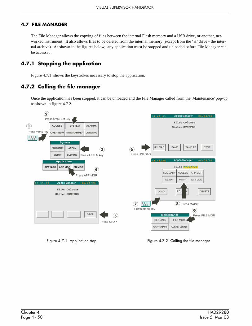
Chapter 4Page 4 - 50
HA029280Issue 5 Mar 08
VISUAL SUPERVISOR HANDBOOK
System
APPLNSUMMARY
CLONINGSETUP
ACCESS
PROGRAMMER
SYSTEM
LOGGING
ALARMS
OVERVIEW
1Press menu key
2Press SYSTEM key
3Press APPLN key
4Press APP MGR
Appl'n Manager 06/04/0616:39:59
File:
State:
Colours
RUNNING
STOP 5Press STOP
APP SUM APP MGR FB MGR
Application
4.7 FILE MANAGER
The File Manager allows the copying of files between the internal Flash memory and a USB drive, or another, net-worked instrument. It also allows files to be deleted from the internal memory (except from the ‘H’ drive - the inter-nal archive). As shown in the figures below, any application must be stopped and unloaded before File Manager canbe accessed.
4.7.1 Stopping the application
Figure 4.7.1 shows the keystrokes necessary to stop the application.
4.7.2 Calling the file manager
Once the application has been stopped, it can be unloaded and the File Manager called from the 'Maintenance' pop-upas shown in figure 4.7.2.
Figure 4.7.1 Application stop Figure 4.7.2 Calling the file manager
Appl'n Manager 06/04/0616:41:05
File:
State:
Colours
STOPPED
UNLOAD SAVE STOPSAVE AS
Appl'n Manager 06/04/0616:41:25
LOAD LD+RUN DELETE
7Press menu key
6Press UNLOAD
8 Press MAINT
9Press FILE MGR
File:
SUMMARY ACCESS APP MGR
SETUP MAINT EVT LOG
????????
Maintenance
CLONING FILE MGR
SOFT OPTS BATCH MAINT

Chapter 4Page 4 - 51
HA029280Issue 5 Mar 08
VISUAL SUPERVISOR HANDBOOK
4.7.3 File Copy and Delete
Operation of the 'FILE MGR' button in the 'Maintenance' pop-up calls the File Manager page. Once this page is ondisplay, either an individual file name can be selected from the relevant drive and the copy or delete key operated, orthe COPY ALL/DEL ALL keys can be used to copy or delete all the files, within the selected filter, on that drive.
CAUTION1. Files of the form _SYSTEM.XYZ* must not be deleted or the instrument will not operate correctly and
revert to a factory configuration2. The file _DEF AULT.OFL must not be deleted or the faceplates in the overview page will fail to operate
correctly ,*XYZ is any three character extension..
Figure 4.7.3 Copy and delete
Node For ELIN systems only, the (decimal) number of the LIN node to be accessed
Device Selectable as E (internal flash memory) or if any of the following are fitted: B (USB Bulkstorage device) or H (internal archive).
Filter Allows file display to be limited to certain types of files.For example, *.* shows all files, whereas, an entry of *.DBF allows only files with .DBFsuffix to appear. See 'File' immediately below.
File Touching this area causes a scroll list of files to be displayed and to be selected (one at a time)for copying or deleting. The range of files displayed can be limited by entering a display'filter' to limit the scroll list to certain file names or file types.
Size Shows the size of the selected file.
Free space Shows the remaining capacity of the drive selected.
File Manager16:57:14
Device:
Filter:
E:
File: _SYSTEM1.UYL
Size: 11395 bytes
Free Space: 628084 bytes
Node: 1
*.*
Confirm DeleteCopy File
File: E:_SYSTEM1.UYL
OK CANCEL
06/04/06
OK CANCEL
Copy to Node: 1Device: E: File:
COPY COPY ALL DELETE DEL ALL
File: E:_SYSTEM1.UYL
CAUTIONFiles must not be deleted from the ‘E’ driveunless it is certain that the control system willnot be impaired by so doing. See the caution-ary notes above.

Chapter 4Page 4 - 52
HA029280Issue 5 Mar 08
VISUAL SUPERVISOR HANDBOOK
4.7.4 Reloading the application
Operation of the menu key, followed by the APP MGR button in the pop-up menu, returns to the Application Managerpage, which allows a file to be selected to be the application. Once a file name has been selected, operation of theLOAD key and then the START key or the LD+RUN key, returns the unit to normal operation.
Figure 4.7.4 Regaining the Application Manager Page
4.8 RECIPE MANAGEMENT
4.8.1 Creating recipe files
A ‘blank’ recipe file (i.e. a recipe file with no values) can be created from the recipe file page. The recipe editor canthen be used to add values.
4.8.2 Recipe editing
The recipe editor is called by pressing ‘EDIT’ from the recipe menu.
Note: For units fitted with the Auditor Option, an edited recipe must be Saved before it can be downloaded.
ADD RECIPE LINEIf a spare line is available, a new line can be added by pressing the ‘ADD LINE’ button. (The Option key may needpressing one or more times in order to display this key.) Once added, the RCP (Recipe) cell at the top left of the dis-play can be pressed to change the name of the selected line.
9Press menu key
10Press APP MGR
Appl'n Manager 06/04/0617:01:57
File: ????????
LOAD LD+RUN DELETE
Appl'n Manager 06/04/0617:01:10
LOAD LD+RUN DELETE
File:
SUMMARY ACCESS APP MGR
SETUP MAINT EVT LOG
????????

Chapter 4Page 4 - 53
HA029280Issue 5 Mar 08
VISUAL SUPERVISOR HANDBOOK
4.8.2 RECIPE EDITING (Cont.)
ADD A VARIABLEA new variable can be added by touching that cell in the left-most (RCP) column, which is immediately above the cellwhere the new variable is to appear. A Properties Menu appears, which allows the variable name and tag references tobe entered.
Note: variables are executed in ‘top-down’ order, so the order in which variables appear can be important.
To add the first variable, press the RCP cell, then the INSERT key on the pop-up menu. The name and tag referencesof the variable can now be entered. If applicable, Capture and Monitor values can also be edited. The verify fieldallows the user to define ’Verify’ as ‘Yes’ or ‘No’. If set to No, the variable is not checked, during download, to en-sure that the value is correctly written. ‘No’ is used, for example, where a variable may reset itself or change.
Figure 4.8.2a shows a typical properties dialogue box.
Figure 4.8.2a Properties dialogue boxTAG REFERENCES
Touching a variable in the RCP column , calls the Properties menu. This menu allows the variable name, tag refer-ences and verification setting to be edited.
RECIPE VALUETouching a value in a recipe column, allows a new value to be entered.
ADDING A RECIPETo add a new recipe, select an existing recipe to act as a model, and touch that recipe’s name. Select NEW from thedialogue box which appears. The new recipe takes the values of the model, and can be edited as required.
DELETING RECIPESTouch the recipe name (at the top of the column), then select DELETE from the pop-up dialogue box.
3/5TRENDRUNNING 05:07:45 2
AmarilloGASCONC
Fred
Gas Mix
Amarillo Q8 EkoFiskRCPMethaneNitrogen
Ethane
PropaneWaterHydrogenSulphideHydrogen
Carbon MonoxideOxygeni Butane
n Butanei Pentane
n Pentanen Hexane
n Heptanen Octanen Nonanen DecaneHelium
90.67243.12840.4676
4.5279
0.8280.00.00.0
0.00.0
0.1037
0.15630.0321
0.04430.0393
0.00.00.00.00.0
90.67243.12840.4676
4.5279
0.82800.00000.00000.0000
0.00000.00000.1037
0.15630.0321
0.04430.0393
0.00000.00000.00000.00000.0000
90.67243.12840.4676
4.5279
0.82800.00000.00000.0000
0.00000.00000.1037
0.15630.0321
0.04430.0393
0.00000.00000.00000.00000.0000
SAVE CAPTURE CAPTURE AS DOWNLOAD ABORT
Carbon Dioxide
O K D E L E T E I N S E R T
Variable Name:
Verify:
Properties
Tag references
Line:
SP:
Carbon Dioxide
YES
1
GasConc.CrbDiOx
F1 F2 F3
F10 F11 F12
F4 F5 F6 F7 F8 F9
F13 F14 F15 F16 F17 F18
F19 F20 F21 F22 F23 F24 F25 F26 F27

Chapter 4Page 4 - 54
HA029280Issue 5 Mar 08
VISUAL SUPERVISOR HANDBOOK
4.8.2 RECIPE EDITING (Cont.)
SAVING RECIPESTo save changes to the current file name, operate the SAVE button. To make a copy of the file, press SAVE AS.
RECIPE FILE PROPERTIESTouching the RCP cell calls the Recipe File properties dialogue box to the display. This gives the name of the recipefile and the line currently selected, as well as details of the previous file edit. The version field is incremented eachtime the file is saved.
Further to this there is an editable timeout field allowing a value to be entered to timeout a successful download of arecipe.
OK INSERTOK INSERT
Id:
File Name:
Line:
Version:
Edited by:
At:
Timeout:
SET1
GASCONIC
1
5
Fred
11:50:57 23/11/00
30 seconds
Figure 4.8.2b Recipe File properties box
4.8.3 Capturing a Recipe
With a recipe file loaded and a recipe selected it is possible to ‘capture’ live values from the running application, fordisplay in the Recipe Monitor page (either in the ‘Capture’ column if available, or in the SP (Live) column if not).Operation of the CAPTURE button in the monitor page overwrites the existing values in the selected recipe. CAP-TURE AS, creates a new recipe with the captured values.
Once values have been captured, they can be modified as required in the Recipe edit page.

Chapter 4Page 4 - 55
HA029280Issue 5 Mar 08
VISUAL SUPERVISOR HANDBOOK
4.9 OEM FEATURES
4.9.1 Intellectual Property Right Protection (IPRP)
The IPRP feature is provided to allow OEMs, for example, to prevent unauthorized copying of application files. Todetermine if a feature is enabled, view the software options page (section 2.1.3).
If IPRP is enabled:1. Files on the E: drive may not be copied from the instrument either to the USB memory stick (if fitted) or via
network (ELIN or FTP) operations.2. All files on the E: drive may be modified using normal user interface operations.3. New files may be added to the E: drive, but they may not be copied from the instrument.4. Existing files may be overwritten by new files, with the same name, across a network.5. Files are ‘scrambled’ when cloned out of the instrument, so clone files can be used only in the source instrument
or in another instrument with the same IPRP password (see below).
MODIFYING IPRP SETTINGSThe procedure for modifying the IPRP settings is to create a text file, to copy it to the E: drive, and then to powercycle the instrument.
The text file must be called _OEM.TXT and consists of a single line containing comma-separated items as follows:OEM,1,current password,new password,enable/disable
Where the items have the following definitions:OEM Non variable text string.1 Non variable value.Current password The current password. As despatched from the factory, this is:
_OEM_OEMIf the current password is entered incorrectly, the file is ignored.
New password The required new password of up to eight characters. If left blank, the password remainsunchanged.
Enable/disable 0 = IPRP disabled (off); 1 = IPRP enabled (on). If left blank, the setting remains unchanged.
For example, to change the default password to ‘Richard1’ and enable IPRP, the file content should be as follows:
OEM,1,_OEM_OEM,Richard1,1
Note: Space characters are included in the password. Commas are not allowable as password characters.

Chapter 4Page 4 - 56
HA029280Issue 5 Mar 08
VISUAL SUPERVISOR HANDBOOK
4.10 BATCH MAINTNEANCE
Whenever a batch is loaded, the instrument seeds the batch id with a sequence number (starting from 00000001) toprovide a unique batch ID. This number increases throughout the life of the instrument to ensure the batch ID isunique within this instrument. If it is ever required to modify this sequence number the BAT MAINT utility may beused to do this. Possible reasons are replacement of existing instrument or to reset after a commissioning phase. Thisutility is accessed as shown in figure 4.10, below.
System
APPLNSUMMARY
CLONINGSETUP
ACCESS
PROGRAMMER
SYSTEM
LOGGING
ALARMS
OVERVIEW
1Press menu key
2Press SYSTEM key
3Press APPLN key
4Press APP MGR
Appl'n Manager 07/04/0609:29:59
File:
State:
Colours
RUNNING
STOP 5Press STOP
APP SUM APP MGR FB MGR
Application
Appl'n Manager 07/04/0609:59:48
File:
State:
Colours
STOPPED
UNLOAD SAVE STOPSAVE AS
Appl'n Manager 07/04/0610:00:06
LOAD LD+RUN DELETE
7Press menu key
6Press UNLOAD
8 Press MAINT
Maintenance 9PressBATCH MAINT
File:
SUMMARY ACCESS APP MGR
SETUP MAINT EVT LOG
????????
CLONING FILE MGR
SOFT OPTS BATCH MAINT
Figure 4.10 Batch Maintenance access
The batch sequence number (ID) that was last used is displayed. This may be modified to a new value (the next batchrun will take this new value +1). The ID is edited by touching the current Id value, then keying in the required valueusing the pop-up keyboard which appears.
This facility must be used with caution as, if multiple log files with the same batch ID are imported into Review soft-ware, it will view them as the same batch. Unless this is the intention, any records of previous batches with the sameID should be removed from Review before the ID is reset.

Chapter 5Page 5 - 1
VISUAL SUPERVISOR HANDBOOK
HA029280Issue 5 Mar 08
CHAPTER 5: CUSTOMISING
This chapter describes how to customise the Standard Interface; it consists of the following sections:5.1 Introduction 5.9 Form files5.2 The System text dictionary 5.10 Recipe files5.3 The Error text dictionary 5.11 The writeable dictionary5.4 The Event text dictionary 5.12 The recipe dictionary5.5 The User text dictionary 5.13 The batch dictionary5.6 The Programmer text dictionary 5.14 Batch files5.7 Panel navigation 5.15 Database change audit trailing5.8 Database names
5.1 INTRODUCTION
5.1 to 5.8, show how to replace the supplied screen-displayed texts with ones more suited to a particular process, in adifferent language and so on.
Each of these can involve either:1. replacing text items displayed by the instrument’s Standard Interface; and/or2. writing new text, either for any other national language versions of the Standard Interface that might be required,
or for any so-called User-screens being developed.
5.9 describes how to format reports. 5.10 to 5.15 contain details of how to create or edit recipe, batch and card-readerfiles.
5.1.1 The dictionaries
Displayed texts are held in files called dictionaries, covered in sections 5.2 to 5.6 and 5.11 to 5.13. There are specificcustomisable dictionary files for each of the following types of texts:1. Standard Interface, excluding the Error and Event messages2. Error messages3. Event messages4. The texts of any User pages (the ‘User screens’)5. Programmer texts.6. Writeable (modifiable) texts for use with the batch system and in reports.7. Recipe texts8. Batch texts
The texts of the Standard Interface are held in the System text dictionary, Error messages are held in the Error Textdictionary, and Event messages are held in the Event Text dictionary. These three dictionaries make up the _system.uylfile.
User screen and Programmer text dictionaries are initially empty, for users to fill as required. These two dictionariesmake up the _user.uyl file.

VISUAL SUPERVISOR HANDBOOK
Chapter 5Page 5 - 2
HA029280Issue 5 Mar 08
5.1.1 THE DICTIONARIES (Cont.)
DICTIONARY NAME FILE NAME RECORD SYNTAXSystem text _system.uyl S<N>,<text>
Error text _system.uyl E<N>,<text>Event text _system.uyl V<N>,<text>User text _user.uyl U<N>,<text>
Programmer text _user.uyl P<N>,<text>Writeable text _user.uyl W<N>,<initial text>
Recipe texts Not applicable Not applicableBatch texts Not applicable Not applicable
where <N> is the index number of the record (section 5.2.2. File structure).
Customising an existing .uyl file or building a new one is done by editing the files on a PC using a standard text editor(for example, Windows Notepad) and then cloning them into the Visual Supervisor by USB device.
5.1.2 Panel navigation and database names
Panel navigation (section 5.7) describes how to change the layout (the architecture) of the Standard Interface. A com-pletely new architecture can be created if required.
Database names (section 5.8) describes how to change the names of function blocks, alarms, and of items called enu-merations which are usually two-state Boolean variables such as ON/OFF and TRUE/FALSE.
5.2 THE SYSTEM TEXT DICTIONARY
The System text dictionary holds all the text displayed by the instrument’s Standard Interface, except for the follow-ing:1 Error messages2 Event messages3 Segment type names, and text in menus and column headers.
Of these, Error messages and Event messages are held in their own dictionaries and can be customised through those.Commands, segment type names, and text in menus and column heads are held elsewhere and cannot be customised.
In customising the System dictionary, it is possible to:1 replace any text item with text for a particular industry or application, and/or2 the text can be internationalised by creating new dictionaries for each of up to ten languages
5.2.1 File structureIn the listing of the System text dictionary in section 5.2.4, the column header running throughout is:
NO. CONTEXT CLASS MAX TEXT
No. Stands for REFERENCE NUMBERCONTEXT Describes the application to which the text relates. For example, STARTUP, COMMS, or
CLOCK.CLASS Describes the type of text. For example, title of a dialogue box, button text, or error message.MAX The maximum permissible length of the replacement text, in number of characters.TEXT The default text that the instrument is supplied with for this item.

Chapter 5Page 5 - 3
VISUAL SUPERVISOR HANDBOOK
HA029280Issue 5 Mar 08
5.2.2 Editing system text
The System text dictionary is held in the _system.uyl file. In the print-out of this file in section 5.2.4:1. Find the text to be replaced (first find its Context, then its Class, then the Text itself)2. Note its reference number3. Key in the reference number, and then the new text, related by the following syntax: S<N>, <text>
where:<N> is the reference number of the record you want to change<text> is the replacement text.
For example, S12,Display error.
For any text item not replaced in the .uyl file, the version in the ROM file will be used.
5.2.3 New language versions
For each language a file called a _system<n>.uyl file must be built, using the same syntax as above. The variable <n>in each file name specifies the particular national language by taking integer values from 0 up to a maximum of 9,one value for each language which is to be available. The correspondence (mapping) between language and integer isdecided by the user.
For example, the file holding terms in English might be the file named _system0.uylwith a typical record S2,FILE UPDATE.
5.2.4 The dictionary
On delivery of the Visual Supervisor, the contents of the System text dictionary (abridged) are as set out below.
Notes:1. Items where ‘ : ’ is the final character always have a space after the ‘ : ’ for formatting purposes2. Leading space characters are significant3. Any printable character of the Unicode Latin-1 set may be used.
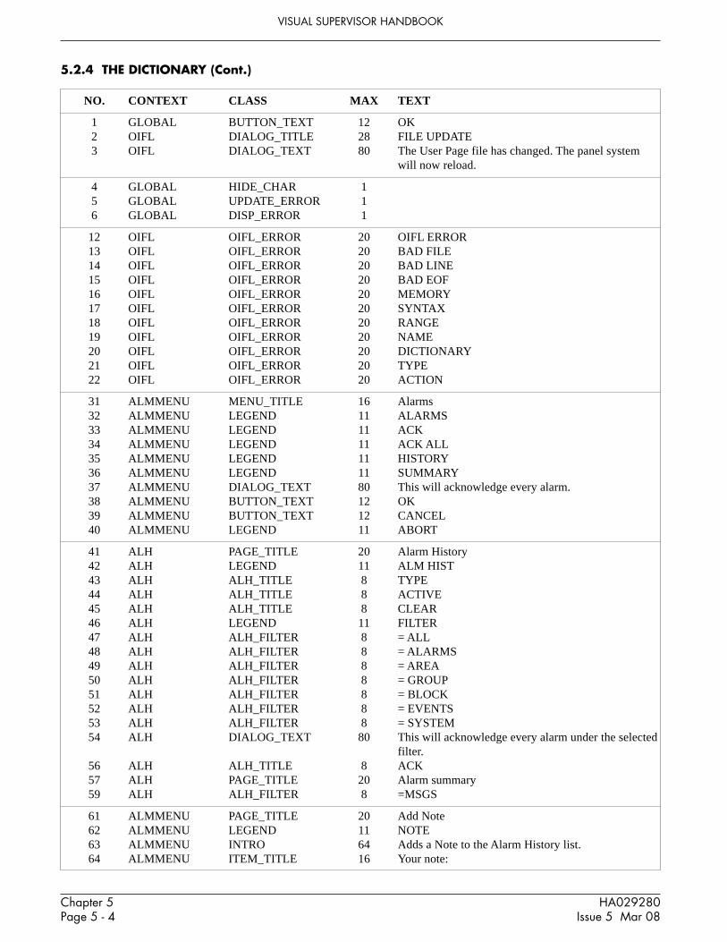
VISUAL SUPERVISOR HANDBOOK
Chapter 5Page 5 - 4
HA029280Issue 5 Mar 08
5.2.4 THE DICTIONARY (Cont.)
NO. CONTEXT CLASS MAX TEXT
1 GLOBAL BUTTON_TEXT 12 OK2 OIFL DIALOG_TITLE 28 FILE UPDATE3 OIFL DIALOG_TEXT 80 The User Page file has changed. The panel system
will now reload.
4 GLOBAL HIDE_CHAR 15 GLOBAL UPDATE_ERROR 16 GLOBAL DISP_ERROR 1
12 OIFL OIFL_ERROR 20 OIFL ERROR13 OIFL OIFL_ERROR 20 BAD FILE14 OIFL OIFL_ERROR 20 BAD LINE15 OIFL OIFL_ERROR 20 BAD EOF16 OIFL OIFL_ERROR 20 MEMORY17 OIFL OIFL_ERROR 20 SYNTAX18 OIFL OIFL_ERROR 20 RANGE19 OIFL OIFL_ERROR 20 NAME20 OIFL OIFL_ERROR 20 DICTIONARY21 OIFL OIFL_ERROR 20 TYPE22 OIFL OIFL_ERROR 20 ACTION
31 ALMMENU MENU_TITLE 16 Alarms32 ALMMENU LEGEND 11 ALARMS33 ALMMENU LEGEND 11 ACK34 ALMMENU LEGEND 11 ACK ALL35 ALMMENU LEGEND 11 HISTORY36 ALMMENU LEGEND 11 SUMMARY37 ALMMENU DIALOG_TEXT 80 This will acknowledge every alarm.38 ALMMENU BUTTON_TEXT 12 OK39 ALMMENU BUTTON_TEXT 12 CANCEL40 ALMMENU LEGEND 11 ABORT
41 ALH PAGE_TITLE 20 Alarm History42 ALH LEGEND 11 ALM HIST43 ALH ALH_TITLE 8 TYPE44 ALH ALH_TITLE 8 ACTIVE45 ALH ALH_TITLE 8 CLEAR46 ALH LEGEND 11 FILTER47 ALH ALH_FILTER 8 = ALL48 ALH ALH_FILTER 8 = ALARMS49 ALH ALH_FILTER 8 = AREA50 ALH ALH_FILTER 8 = GROUP51 ALH ALH_FILTER 8 = BLOCK52 ALH ALH_FILTER 8 = EVENTS53 ALH ALH_FILTER 8 = SYSTEM54 ALH DIALOG_TEXT 80 This will acknowledge every alarm under the selected
filter.56 ALH ALH_TITLE 8 ACK57 ALH PAGE_TITLE 20 Alarm summary59 ALH ALH_FILTER 8 =MSGS
61 ALMMENU PAGE_TITLE 20 Add Note62 ALMMENU LEGEND 11 NOTE63 ALMMENU INTRO 64 Adds a Note to the Alarm History list.64 ALMMENU ITEM_TITLE 16 Your note:

Chapter 5Page 5 - 5
VISUAL SUPERVISOR HANDBOOK
HA029280Issue 5 Mar 08
66 ALMMENU LEGEND 11 LOG
67 ALH PAGE_TITLE 20 Event Log
68 ALMMENU LEGEND 11 EVT LOG71 ALMMENU PAGE_TITLE 20 Alarm Archive72 ALMMENU LEGEND 11 ARCHIVE73 ALMMENU INTRO 64 Archive to disk the alarm history74 ALMMENU DIALOGUE_TITLE 28 Acknowledging All Cached Block Alarms75 ALMMENU ITEM_TITLE 16 Remaining:76 ALMMENU ITEM_TITLE 16 Block:
77 PRINTER ALM_TYPE 3 ACK78 PRINTER ALM_TYPE 3 ACT79 PRINTER ALM_TYPE 3 CLR
90 APPMGR DIALOG_TITLE 28 Load Error
91 FATAL FATAL_ERROR 20 No cold/hot start92 FATAL FATAL_ERROR 20 No hot start93 FATAL FATAL_ERROR 20 No cold start
94 SYSTEM DIALOG_TITLE 28 Missing template libraries
101 MONTH MONTH 3 Jan102 MONTH MONTH 3 Feb103 MONTH MONTH 3 Mar104 MONTH MONTH 3 Apr105 MONTH MONTH 3 May106 MONTH MONTH 3 Jun107 MONTH MONTH 3 Jul108 MONTH MONTH 3 Aug109 MONTH MONTH 3 Sep110 MONTH MONTH 3 Oct111 MONTH MONTH 3 Nov112 MONTH MONTH 3 Dec
113 ALH DATE POOR CHAR 1 *114 ALH TIME POOR CHAR 1 *
120 GLOBAL BUTTON_TEXT 12 OK121 GLOBAL BUTTON_TEXT 12 OK ALL122 GLOBAL BUTTON_TEXT 12 CANCEL123 GLOBAL BUTTON_TEXT 12 ABORT124 GLOBAL BUTTON_TEXT 12 SKIP125 GLOBAL BUTTON_TEXT 12 SAVE126 GLOBAL BUTTON_TEXT 12 ERROR
127 GLOBAL SYSSUM_ITEM 8 <NONE>128 GLOBAL BUTTON_TEXT 12 NO129 GLOBAL BUTTON_TEXT 12 YES
130 SYSMENU MENU_TITLE 16 System131 SYSMENU LEGEND 11 SYSTEM132 SYSSUM PAGE_TITLE 20 System Summary133 SYSSUM LEGEND 11 SUMMARY134 SYSSUM ITEM_TITLE 18 Instrument type:136 SYSSUM ITEM_TITLE 18 Touch/keypad:137 SYSSUM ITEM_TITLE 18 Firmware:
5.2.4 THE DICTIONARY (Cont.)
No. Context Class Max Text

VISUAL SUPERVISOR HANDBOOK
Chapter 5Page 5 - 6
HA029280Issue 5 Mar 08
138 SYSSUM ITEM_TITLE 18 Media:139 SYSSUM ITEM_TITLE 18 Option cards:140 SYSSUM SYSSUM_ITEM 8 Eycon-10, or Eycon-20 according to model141 SYSSUM SYSSUM_ITEM 8 Standard145 SYSSUM SYSSUM_ITEM 8 kBytes146 SYSSUM ITEM_TITLE 18 DRAM:147 SYSSUM ITEM_TITLE 18 SRAM:150 SYSSUM SYSSUM_ITEM 8 TOUCH151 SYSSUM SYSSUM_ITEM 8 KEYPAD154 SYSSUM SYSSUM_ITEM 8 MBytes157 SYSSUM ITEM_TITLE 8 Internal Archive:158 SYSSUM SYSSUM_ITEM 8 IDE159 SYSSUM ITEM_TITLE 18 USB(Bulk)160 SYSSUM PARA 20 Software options163 SYSSUM SYSSUM_ITEM 8 ETHERNET166 SYSSUM SYSSUM_ITEM 8 Report167 SYSSUM SYSSUM_ITEM 8 Recipe168 SYSSUM ITEM_TITLE 18 Reader:169 SYSSUM ITEM_TITLE 18 Batch:
170 APPSUM PAGE_TITLE 20 Appl’n Summary171 APPSUM LEGEND 11 APP SUM172 APPSUM ITEM_TITLE 16 Application:173 APPSUM ITEM_TITLE 16 Machine State:174 APPSUM PARA 24 Memory Usage180 APPSUM APPSUM_STATE 10 OFF181 APPSUM APPSUM_STATE 10 RESET182 APPSUM APPSUM_STATE 10 IDLE183 APPSUM APPSUM_STATE 10 RUNNING184 APPSUM APPSUM_STATE 10 STOPPED185 APPSUM APPSUM_STATE 10 ERROR189 APPSUM ITWM_TITLE 16 Ctrl VolDB:190 APPSUM ITEM_UNITS 9 kB191 APPSUM ITEM_TITLE 16 Control DB:192 APPSUM ITEM_TITLE 16 Programmer:193 APPSUM ITEM_TITLE 16 SFC DB:194 APPSUM ITEM_TITLE 16 SFC ST:195 APPSUM ITEM_TITLE 16 Modbus slave:196 APPSUM ITEM_TITLE 16 Modbus master:197 APPSUM ITEM_TITLE 16 transient:198 APPSUM ITEM_TITLE 16 Profibus Master:
200 STARTUP PAGE_TITLE 20 Startup Strategy201 STARTUP LEGEND 11 STARTUP202 STARTUP ITEM_TITLE 18 Hot Start:203 STARTUP ITEM_TITLE 18 Warm Start:204 STARTUP ITEM_TITLE 18 Cold Start:205 STARTUP ITEM_TITLE 18 Startup State:206 STARTUP ITEM_TITLE 18 Hot-start time:207 STARTUP ITEM_TITLE 18 Brown-out time:
220 COMMS PAGE_TITLE 20 Comms Setup221 COMMS LEGEND 18 COMMS222 COMMS DIALOG_TEXT 80 The settings specified are invalid.223 COMMS DIALOG_TITLE 28 Hardware check224 COMMS DIALOG_TEXT 80 IMPORTANT: Ensure comms cables are unplugged
before pressing ‘OK’ to continue.
5.2.4 THE DICTIONARY (Cont.)
No. Context Class Max Text

Chapter 5Page 5 - 7
VISUAL SUPERVISOR HANDBOOK
HA029280Issue 5 Mar 08
228 COMMS COMMS_ITEM 8 Ethernet240 COMMS COMMS_ATTR 9 PORT241 COMMS COMMS_ATTR 9 Hardware242 COMMS COMMS_ATTR 9 Protocol243 COMMS COMMS_ATTR 9 Node No.244 COMMS COMMS_ATTR 9 Baud245 COMMS COMMS_ATTR 9 Parity246 COMMS COMMS_ATTR 9 Data Bits247 COMMS COMMS_ATTR 9 Stop Bits248 COMMS COMMS_ATTR 9 Timeout249 COMMS COMMS_ATTR 9 Talk Thru251 COMMS COMMS_ITEM 8 None253 COMMS COMMS_ITEM 8 TermCfg254 COMMS COMMS_ITEM 8 Modbus/S255 COMMS COMMS_ITEM 8 Modbus/M261 COMMS COMMS_ITEM 8 NONE262 COMMS COMMS_ITEM 8 EVEN263 COMMS COMMS_ITEM 8 ODD266 COMMS COMMS_ITEM 8 RS422267 COMMS COMMS_ITEM 8 RS485270 CLOCK PAGE_TITLE 20 Clock Setup271 CLOCK LEGEND 11 CLOCK272 CLOCK ITEM_TITLE 16 Date:273 CLOCK ITEM_TITLE 16 Time:274 CLOCK BUTTON_TEXT 12 SET275 CLOCK BUTTON_TEXT 12 Hr +1276 CLOCK BUTTON_TEXT 12 Hr -1277 CLOCK INTRO 64 Clock configured as master278 CLOCK INTRO 64 Clock configured as slave
280 SYSSUM ITEM_TITLE 18 SPP/SFC281 SYSSUM ITEM 8 SPP282 SYSSUM ITEM 8 SFC283 SYSSUM ITEM 8 DB288 SYSSUM ITEM_TITLE 21 IPR Protection:289 SYSSUM SYSSUM_ITEM 8 Auditor:
290 INTERNAT PAGE_TITLE 20 Internationalise291 INTERNAT LEGEND 11 INTERNAT292 INTERNAT ITEM_TITLE 14 Language:293 INTERNAT ITEM_TITLE 14 Date Format:294 INTERNAT ITEM_TITLE 14 Time Format:295 INTERNAT ITEM_TITLE 14 Duration Fmt:296 INTERNAT BUTTON_TEXT 12 CHANGE300 INTERNAT LANGUAGE 12 English301 INTERNAT LANGUAGE 12 French302 INTERNAT LANGUAGE 12 German303 INTERNAT LANGUAGE 12 Italian304 INTERNAT LANGUAGE 12 Spanish305 INTERNAT LANGUAGE 12 Lang_5306 INTERNAT LANGUAGE 12 Lang_6307 INTERNAT LANGUAGE 12 Lang_7308 INTERNAT LANGUAGE 12 Lang_8309 INTERNAT LANGUAGE 16 Portuguese
5.2.4 THE DICTIONARY (Cont.)
No. Context Class Max Text

VISUAL SUPERVISOR HANDBOOK
Chapter 5Page 5 - 8
HA029280Issue 5 Mar 08
310 PANEL PAGE_TITLE 20 Panel Setup311 PANEL LEGEND 11 PANEL312 PANEL PARA 24 BACK-LIGHT313 PANEL ITEM_TITLE 32 Brightness:314 PANEL ITEM_TITLE 32 Saver brightness:315 PANEL ITEM_TITLE 32 Timeout:316 PANEL PARA 24 PAGE TIMEOUTS317 PANEL ITEM_TITLE 32 Home:318 PANEL ITEM_TITLE 32 Pop-up:319 PANEL ITEM_TITLE 32 Data Entry:320 PANEL ITEM_UNITS 9 minutes321 PANEL ITEM_UNITS 9 seconds322 PANEL ITEM 16 100%323 PANEL ITEM 16 90%324 PANEL ITEM 16 80%325 PANEL ITEM 16 70%326 PANEL ITEM 16 60%327 PANEL ITEM 16 50%328 PANEL ITEM 16 40%329 PANEL ITEM 16 30%330 PANEL ITEM 16 20%331 PANEL ITEM_TITLE 20 This item allows an access level timeout to be entered
(Section 4.5.5.3). If a non-zero value is entered, thenthe Access level will return to ‘Locked’ whenever thetime between screen presses is greater than thetimeout period.
332 PANEL ITEM_TITLE 16 SIZES333 PANEL ITEM 16 Standard334 PANEL ITEM 26 Small339 PANEL ITEM_UNITS 9 days
340 FILEMGR BUTTON_TEXT 12 COPY ALL341 FILEMGR PAGE_TITLE 20 Copy Files342 FILEMGR BUTTON_TEXT 16 DEL ALL343 FILEMGR PAGE_TITLE 20 Confirm Delete All344 FILEMGR ITEM_FILE 16 Files:
360 ACCESS PAGE_TITLE 20 Security Access361 ACCESS LEGEND 11 ACCESS362 ACCESS INTRO 64 Enter required level and password, then CHANGE363 ACCESS ITEM_TITLE 18 Current Level:364 ACCESS ITEM_TITLE 18 New Level:365 ACCESS ITEM_TITLE 18 Password:366 ACCESS BUTTON_TEXT 12 CHANGE367 ACCESS BUTTON_TEXT 12 PASSWDS368 ACCESS PAGE_TITLE 20 Passwords369 ACCESS PAGE_TITLE 28 Confirm Password370 ACCESS INTRO 64 Please re-enter top-level password:371 ACCESS ACCESS_LEVEL 10 LOCKED372 ACCESS ACCESS_LEVEL 10 OPERATOR373 ACCESS ACCESS_LEVEL 10 COMMISSION374 ACCESS ACCESS_LEVEL 10 ENGINEER375 ACCESS ACCESS_LEVEL 10 ADMIN
5.2.4 THE DICTIONARY (Cont.)
No. Context Class Max Text

Chapter 5Page 5 - 9
VISUAL SUPERVISOR HANDBOOK
HA029280Issue 5 Mar 08
380 APPMGR PAGE_TITLE 20 Appl’n Manager381 APPMGR LEGEND 11 APP MGR382 APPMGR ITEM_TITLE 16 File:383 APPMGR ITEM_TITLE 16 State:384 APPMGR BUTTON_TEXT 12 LOAD385 APPMGR BUTTON_TEXT 12 LD+RUN386 APPMGR BUTTON_TEXT 12 UNLOAD387 APPMGR BUTTON_TEXT 12 SAVE388 APPMGR BUTTON_TEXT 12 SAVE AS389 APPMGR BUTTON_TEXT 12 DELETE390 APPMGR BUTTON_TEXT 12 STOP391 APPMGR BUTTON_TEXT 12 START392 APPMGR DIALOG_TITLE 28 Confirm Delete393 APPMGR MESSAGE 128 Application management is already in progress else-
where394 APPMGR DIALOG_TITLE 28 Saving
396 APPMENU MENU_TITLE 16 Application397 APPMENU LEGEND 11 APPLN
398 SETMENU MENU_TITLE 16 Setup399 SETMENU LEGEND 11 SETUP
400 SPP SPP_STATUS 8 RESET401 SPP SPP_STATUS 8 LOADING402 SPP SPP_STATUS 8 PRE_RUN403 SPP SPP_STATUS 8 RUNNING404 SPP SPP_STATUS 8 HELD405 SPP SPP_STATUS 8 HELDBACK406 SPP SPP_STATUS 8 COMPLETE407 SPP SPP_STATUS 8 IDLE408 SPP SPP_STATUS 8 POST_RUN409 SPP SPP_STATUS 8 ERROR410 SPP SPP_FP_VALUE 8 CLOSED411 SPP SPP_FP_VALUE 8 OPEN412 SPP ITEM_TITLE 16 Segment:413 SPP ITEM_TITLE 16 Setpoint:414 SPP ITEM_TITLE 16 Ramp at:415 SPP ITEM_TITLE 16 to:416 SPP BUTTON_TEXT 12 DONE417 SPP PAGE_TITLE 18 Current Program418 SPP PARA 20 Program419 SPP ITEM_TITLE 16 Name:420 SPP ITEM_TITLE 16 Status:421 SPP ITEM_TITLE 16 Duration:422 SPP ITEM_TITLE 16 Completion:423 SPP ITEM_TITLE 16 Iteration:424 SPP Special 1 /425 SPP PARA 24 Segment426 SPP ITEM_TITLE 16 Name:427 SPP ITEM_TITLE 16 Time Remaining:428 SPP BUTTON_TEXT 12 RUN429 SPP BUTTON_TEXT 12 HOLD430 SPP BUTTON_TEXT 12 ABORT
5.2.4 THE DICTIONARY (Cont.)
No. Context Class Max Text

VISUAL SUPERVISOR HANDBOOK
Chapter 5Page 5 - 10
HA029280Issue 5 Mar 08
431 SPP PAGE_TITLE 20 Load/Save Program432 SPP ITEM_TITLE 16 File Name:433 SPP BUTTON_TEXT 12 LOAD434 SPP BUTTON_TEXT 12 SAVE435 SPP BUTTON_TEXT 12 SAVE AS436 SPP BUTTON_TEXT 12 DELETE437 SPP PAGE_TITLE 20 Schedule Program438 SPP ITEM_TITLE 17 File Name:439 SPP ITEM_TITLE 17 Start Date:440 SPP ITEM_TITLE 17 Start Time:441 SPP ITEM_TITLE 16 Iterations:442 SPP BUTTON_TEXT 12 CLEAR443 SPP BUTTON_TEXT 12 ACCEPT444 SPP SPP_CELL 18 SP445 SPP SPP_CELL_ABBR 8 D446 SPP SPP_CELL_ABBR 8 S447 SPP Special 2 to448 SPP SPP_CELL_ABBR 8 R449 SPP Special 2 R@450 SPP SPP_CELL_ABBR 8 Servo SP451 SPP SPP_CELL_ABBR 8 Servo PV452 SPP PAGE_TITLE 20 Save As...453 SPP ITEM_TITLE 16 File Name:455 SPP DIALOG_TEXT 80 Overwriting456 SPP DIALOG_TITLE 28 PROGRAM SAVE457 SPP BUTTON_TEXT 12 OK458 SPP BUTTON_TEXT 12 CANCEL459 SPP DIALOG_TEXT 80 Deleting460 SPP DIALOG_TITLE 28 PROGRAM DELETE461 SPP BUTTON_TEXT 12 OK462 SPP BUTTON_TEXT 12 CANCEL463 SPP DIALOG_TEXT 80 File Saved464 SPP DIALOG_TITLE 28 PROGRAM SAVE465 SPP BUTTON_TEXT 12 OK466 SPP DIALOG_TEXT 80 Program File not found467 SPP DIALOG_TEXT 80 Program File too large468 SPP DIALOG_TEXT 80 File read error469 SPP DIALOG_TEXT 80 File write error470 SPP DIALOG_TEXT 80 Unresolved block references471 SPP DIALOG_TEXT 80 Program Already Running472 SPP DIALOG_TEXT 80 Insufficient file space473 SPP DIALOG_TEXT 80 Unrecognised file format474 SPP DIALOG_TEXT 80 Schedule already loaded475 SPP DIALOG_TEXT 80 Max nested subprograms limit exceeded476 SPP DIALOG_TITLE 28 PROGRAM LOAD/SAVE ERROR477 SPP BUTTON_TEXT 12 OK478 SPP MENU_TITLE 11 Programmer479 SPP LEGEND 11 MONITOR480 SPP LEGEND 11 PROGRAMS481 SPP LEGEND 11 SCHEDULE482 SPP LEGEND 11 PREVIEW483 SPP LEGEND 11 PRE-PLOT
5.2.4 THE DICTIONARY (Cont.)
No. Context Class Max Text

Chapter 5Page 5 - 11
VISUAL SUPERVISOR HANDBOOK
HA029280Issue 5 Mar 08
484 SPP LEGEND 11 EDIT485 SPP LEGEND 11 PROGRAMMER486 SPP SPP_FP_VALUE 8 NODATA487 SPP ITEM_TITLE 16 Run From:488 SPP ITEM_TITLE 16 Name:489 SPP BUTTON_TEXT 12 CANCEL490 SPP LEGEND 11 RUN FROM491 SPP BUTTON_TEXT 12 RUN492 SPP ITEM_TITLE 16 Duration:493 SPP ITEM_TITLE 16 Time Through:494 SPP DIALOG_TEXT 80 A program is scheduled. Continue with LOAD?495 SPP DIALOG_TITLE 28 LOAD PROGRAM496 SPP PARA 24 Current Schedule:497 SPP DIALOG_TITLE 28 UNSAVED EDITS498 SPP DIALOG_TEXT 80 This operation will result in the loss of edits which
have not yet been saved.499 SPP DIALOG_TITLE 28 RAMP TYPE CHANGE500 SPP DIALOG_TEXT 80 This will require other ramp types in this segment to
be changed.501 SPP BUTTON_TEXT 12 NEW502 SPP PAGE_TITLE 20 New Program503 SPP PAGE_TITLE 20 Load Program504 SPP PAGE_TITLE 20 Properties505 SPP SPP_HOLDBACK 8 Holdback506 SPP ITEM_TITLE 16 Mode:507 SPP ITEM_TITLE 16 Value:508 SPP SPP_HOLDBACK 8 NONE509 SPP SPP_HOLDBACK 8 LOW510 SPP SPP_HOLDBACK 8 HIGH511 SPP SPP_HOLDBACK 8 HIGH&LOW512 SPP ITEM_TITLE 16 Duration:513 SPP BUTTON_TEXT 12 INS SEG514 SPP BUTTON_TEXT 12 DEL SEG515 SPP PAGE_TITLE 20 New Segment516 SPP PAGE_TITLE 20 Confirm Delete517 SPP ITEM 16 (Continuous)518 SPP MESSAGE 128 Building Display, please wait519 SPP ITEM_TITLE 16 Type:520 SPP SPP_CELL 8 Dwell521 SPP SPP_CELL 18 Step522 SPP SPP_CELL 18 Ramp523 SPP SPP_CELL 18 Ramp@524 SPP SPP_CELL 18 Expressn525 SPP SPP_CELL 18 Servo SP526 SPP SPP_CELL 18 Servo PV528 SPP SPP_CELL 18 Dwell529 SPP SPP_CELL 18 Step532 SPP SPP_CELL 18 Expressn536 SPP ITEM_TITLE 20 At End:537 SPP SPP_AT_END 24 Indefinite Dwell538 SPP SPP_AT_END 24 Starting Values539 SPP ITEM_TITLE 16 Ref:540 SPP DIALOG_TEXT 80 Program Limits Exceeded
5.2.4 THE DICTIONARY (Cont.)
No. Context Class Max Text

VISUAL SUPERVISOR HANDBOOK
Chapter 5Page 5 - 12
HA029280Issue 5 Mar 08
550 SPP ITEM_TITLE 20 Rate Units:551 SPP SPP_RATE_UNITS 16 Seconds552 SPP SPP_RATE_UNITS 16 Minutes553 SPP SPP_RATE_UNITS 16 Hours554 SPP SPP_RATE_UNITS 16 days555 SPP DIALOG_TEXT 80 No program loaded561 SPP ITEM_TITLE 16 Id:562 SPP DIALOG_TEXT 80 Common Block Refs563 SPP ITEM_TITLE 16 Iterations:570 SPP BUTTON_TEXT 12 SKIP571 SPP BUTTON_TEXT 12 LAYOUT572 SPP PAGE_TITLE 20 Editor layout573 SPP ITEM_TITLE 16 Long SP names:574 SPP ITEM_TITLE 16 Segment start:575 SPP ITEM_TITLE 16 Segment duration:576 SPP ITEM_TITLE 16 Segment finish:577 SPP ITEM_TITLE 16 Start Time:578 SPP ITEM_TITLE 16 Finish Time:
590 Audit ITEM 16 DYNAMIC591 Audit ITEM 16 BURST592 Audit ITEM 16 INITIAL
598 SIGN BUTTON_TEXT 12 OK599 SIGN BUTTON_TEXT 12 CANCEL600 SIGN PAGE_TITLE 20 Signature601 SIGN PAGE_TITLE 20 Confirmation602 SIGN PARA 24 Authorised by603 SIGN ITEM_TITLE 16 Reason:604 SIGN PARA 24 Signed by605 SIGN ITEM_TITLE 16 Old Value:606 SIGN ITEM_TITLE 16 New Value:607 SIGN ITEM_TITLE 16 Confirm Action:608 SIGN PAGE_TITLE 20 Signature Rejected609 SIGN ITEM_TITLE 16 Action Result:
700 LOGGING MENU_TITLE 16 Logging701 LOGGING LEGEND 11 LOGGING702 LOGGING LEGEND 11 MONITOR
704 LOGGING LEGEND 11 MANAGE705 LOGGING LEGEND 11 GROUPS706 LOGGING PAGE_TITLE 20 Logging Monitor707 LOGGING PAGE_TITLE 20 Logging Groups709 LOGGING PAGE_TITLE 20 Archive Manage711 LOGGING ITEM_TITLE 17 File Name:712 LOGGING ITEM_TITLE 17 File Type:715 LOGGING BUTTON_TEXT 12 MONITOR717 LOGGING BUTTON_TEXT 12 MANAGE718 LOGGING BUTTON_TEXT 12 GROUPS
720 LOGGRP MESSAGE 128 No logging groups configured721 LOGGRP ITEM_TITLE 17 Group Name:722 LOGGRP ITEM_TITLE 17 Logging:723 LOGGRP ITEM_TITLE 17 Archive Int:
5.2.4 THE DICTIONARY (Cont.)
No. Context Class Max Text

Chapter 5Page 5 - 13
VISUAL SUPERVISOR HANDBOOK
HA029280Issue 5 Mar 08
725 LOGGRP ITEM_TITLE 17 Name Type:726 LOGGRP PARA 24 Configuration727 LOGGRP ITEM_TITLE 17 Column Titles:728 LOGGRP ITEM_TITLE 17 Date Format:731 LOGGRP BUTTON_TEXT 12 SAVE732 LOGGRP BUTTON_TEXT 12 LOG NOW
741 LOGGING ITEM 13 ASCII743 LOGGING ITEM 13 UHH
745 LOGGRP ITEM 13 Normal746 LOGGRP ITEM 13 High751 LOGGRP ITEM 13 ON752 LOGGRP ITEM 13 OFF753 LOGGRP ITEM 13 TRIGGER755 LOGGRP ITEM 13 Text758 LOGGRP ITEM 13 Sequence756 LOGGRP ITEM 13 Hourly757 LOGGRP ITEM 13 Daily761 LOGGRP ITEM 13 Date Time762 LOGGRP ITEM 13 Spreadsheet763 LOGGRP ITEM 13 Integer764 LOGGRP ITEM 13 Duration765 LOGGRP ITEM 13 Days766 LOGGRP ITEM 13 DHMS767 LOGGRP ITEM 13 Present768 LOGGRP ITEM 13 Absent
770 LOGAMAN ITEM 16 Files Exported:771 LOGAMAN ITEM 16 Files Skipped:772 LOGAMAN ITEM 16 Page Locked:773 LOGAMAN DIALOGUE_TITLE 28 Archive Manager Export774 LOGAMAN DIALOG_TEXT 80 Complete. Device may now be removed.775 LOGAMAN DIALOG_TEXT 90 Do you wish to skip ALL duplicate files, i.e. never
overwrite files on the export device?776 LOGAMAN DIALOG_TEXT 80 Export device is full. Replace device and press OK to
continue.777 LOGAMAN BUTTON_TEXT 12 EXPORT ALL778 LOGAMAN ITEM 16 Export device:
779 LOGGING ITEM_UNITS 9 Bytes780 LOGGING ITEM_UNITS 9 KBytes
781 LOGMON ITEM_TITLE 16 Media Size:782 LOGMON ITEM_TITLE 16 Free Space:783 LOGMON ITEM_TITLE 16 Logging:784 LOGMON ITEM_TITLE 16 Free Time:785 LOGMON ITEM 8 ON786 LOGMON ITEM 8 OFF787 LOGMON ITEM 8 On Event
789 LOGAMAN ITEM 16 Files796 LOGAMAN BUTTON_TEXT 12 EXPORT797 LOGAMAN MESSAGE 128 Please wait…798 LOGAMAN ITEM_TITLE 16 File Size:799 LOGAMAN BUTTON_TEXT 12 DELETE
5.2.4 THE DICTIONARY (Cont.)
No. Context Class Max Text

VISUAL SUPERVISOR HANDBOOK
Chapter 5Page 5 - 14
HA029280Issue 5 Mar 08
800 CLONE PAGE_TITLE 20 Cloning801 CLONE LEGEND 11 CLONING802 CLONE ITEM 16 System803 CLONE ITEM 16 Application804 CLONE ITEM 16 ALL805 CLONE BUTTON_TEXT 12 EXPORT806 CLONE BUTTON_TEXT 12 IMPORT807 CLONE INTRO 64 System Data808 CLONE ITEM_TITLE 22 Config Options:809 CLONE ITEM_TITLE 22 Config Resources:810 CLONE ITEM_TITLE 22 Dictionaries:811 CLONE ITEM_TITLE 18 User Pages:812 CLONE INTRO 64 Application Data813 CLONE ITEM_TITLE 22 Control Database:814 CLONE ITEM_TITLE 22 SFCs:815 CLONE ITEM_TITLE 22 Programs/Recipes:816 CLONE ITEM_TITLE 22 User Pages:817 CLONE ITEM_TITLE 22 Comms Profiles:818 CLONE BUTTON_TEXT 12 CLEAR819 CLONE BUTTON_TEXT 12 DELETE820 CLONE ITEM_TITLE 22 Exporting:821 CLONE ITEM_TITLE 22 Importing:822 CLONE MESSAGE 128 Aborting...823 CLONE DIALOG_TEXT 80 Storage device not present. Insert, then select OK to
continue.
824 CLONE DIALOG_TEXT 80 This file already exists. Do you wish to overwrite it?825 CLONE DIALOG_TEXT 80 Destination device is full!826 CLONE DIALOG_TEXT 80 Error encountered when copying file827 CLONE DIALOG_TEXT 80 Destination file exists but source file does not. Re-
move it?828 CLONE DIALOG_TEXT 80 No .RUN file found829 CLONE DIALOG_TEXT 80 Multiple .RUN files found
839 CLONE DIALOG_TEXT 80 Storage device corrupted. Replace then select OK tocontinue.
840 AGP PAGE_TITLE 20 Overview841 AGP LEGEND 11 OVERVIEW842 AGP BUTTON_TEXT 12 AUTO843 AGP BUTTON_TEXT 12 MANUAL845 AGP BUTTON_TEXT 8 VIEW846 AGP BUTTON_TEXT 8 LIVE
930 MAINTMEN MENU_TITLE 16 Maintenance931 MAINTMEN LEGEND 11 MAINT
932 FILEMGR PAGE_TITLE 20 File Manager933 FILEMGR LEGEND 11 FILE MGR934 FILEMGR ITEM_TITLE 16 Device:935 FILEMGR ITEM_TITLE 16 Filter:936 FILEMGR ITEM_TITLE 16 File:937 FILEMGR ITEM_TITLE 16 Size:938 FILEMGR ITEM_TITLE 16 Free Space:939 FILEMGR ITEM_UNITS 9 Bytes
5.2.4 THE DICTIONARY (Cont.)
No. Context Class Max Text

Chapter 5Page 5 - 15
VISUAL SUPERVISOR HANDBOOK
HA029280Issue 5 Mar 08
940 FILEMGR BUTTON_TEXT 12 COPY941 FILEMGR BUTTON_TEXT 12 DELETE942 FILEMGR PAGE_TITLE 20 Copy File943 FILEMGR PARA 24 Copy To944 FILEMGR PAGE_TITLE 20 Confirm Delete945 FILEMGR ITEM_TITLE 16 Segment:946 FILEMGR ITEM_TITLE 16 Node:947 FILEMGR ITEM-UNITS 9 (Local)948 FILEMGR MESSAGE 128 Remote file access. Please wait...
951 AGP ITEM_TITLE 12 Missing952 AGP ITEM_TITLE 12 Wrong953 AGP ITEM_TITLE 12 Unknown954 AGP ITEM_TITLE 12 Comm Err961 AGP ITEM_TITLE 12 Sensor Break962 AGP ITEM_TITLE 12 CJC Fail963 AGP ITEM_TITLE 12 Not Used964 AGP ITEM_TITLE 12 OP Sat965 AGP ITEM_TITLE 12 Init966 AGP ITEM_TITLE 12 Inv Cal968 AGP ITEM_TITLE 12 Mod Fail970 AGP ITEM_TITLE 3 AI2971 AGP ITEM_TITLE 3 DI4972 AGP ITEM_TITLE 3 DO4973 AGP ITEM_TITLE 3 AO2974 AGP ITEM_TITLE 3 AI3975 AGP ITEM_TITLE 3 DI8976 AGP ITEM_TITLE 3 AI4977 AGP ITEM_TITLE 3 AO4978 AGP ITEM_TITLE 3 DO8979 AGP ITEM_TITLE 3 AI4980 AGP ITEM_TITLE 3 DI6990 AGP ITEM_TITLE 16 XP991 AGP ITEM_TITLE 16 TI992 AGP ITEM_TITLE 16 TD993 AGP ITEM_TITLE 16 RCG994 AGP ITEM_TITLE 16 CBH995 AGP ITEM_TITLE 16 CBL996 AGP ITEM_TITLE 16 MR997 AGP ITEM_TITLE 16 Act1000 AGP PAGE_TITLE 20 FB Manager1001 AGP LEGEND 11 FB MGR
1002 FB_MGR ITEM_TITLE 16 Block name:1003 FB_MGR ITEM_TITLE 16 Block type:1004 FB_MGR ITEM_TITLE 16 Cached from:1005 FB_MGR ITEM_TITLE 4 ms1006 FB_MGR ITEM_TITLE 16 Update rate:1007 FB_MGR ITEM_TITLE 16 Update rate:1008 FB_MGR ITEM_TITLE 16 Update rate:1009 FB_MGR ITEM 16 No connections
1010 ACCESS INTRO 64 User ID and password, then LOG ON1011 ACCESS ITEM_TITLE 18 Ident:
5.2.4 THE DICTIONARY (Cont.)
No. Context Class Max Text

VISUAL SUPERVISOR HANDBOOK
Chapter 5Page 5 - 16
HA029280Issue 5 Mar 08
1012 ACCESS ITEM_TITLE 18 Name:1013 ACCESS BUTTON_TEXT 12 LOG ON1014 ACCESS ITEM_TITLE 18 Access:1015 ACCESS PAGE_TITLE 20 User Password1016 ACCESS INTRO 64 please re-enter User password:1017 ACCESS BUTTON_TEXT 12 PASSWD1018 ACCESS BUTTON_TEXT 12 USERS1020 ACCESS BUTTON_TEXT 12 LOG OFF1021 ACCESS INTRO 64 To change to Multi-User mode, select OK. See docu-
mentation for password information1023 ACCESS PAGE_TITLE 20 Multi-User select1024 ACCESS DIALOG_TEXT 80 Changing to multi_user mode will be irreversible!
Select OK to continue1025 ACCESS DIALOGUE_TITLE 28 Confirm Multi-User mode1026 ACCESS COL_TITLE 10 Identity1027 ACCESS COL_TITLE 10 Reference1028 ACCESS COL_TITLE 10 Name1029 ACCESS COL_TITLE 10 Access1030 ACCESS ITEM_TITLE 18 Identity:1031 ACCESS ITEM_TITLE 18 Password:1032 ACCESS ITEM_TITLE 18 Confirm:1033 ACCESS BUTTON_TEXT 12 NEW1034 ACCESS BUTTON_TEXT 12 DELETE1035 ACCESS DIALOGUE_TITLE 28 Delete User1036 ACCESS DIALOGUE_TITLE 28 New User1037 ACCESS MESSAGE 128 Sorting entries, please wait1038 ACCESS BUTTON_TEXT 12 DISABLE1039 ACCESS MESSAGE 128 Your password has expired. You must change it now.
1060 CLONE ITEM_TITLE 22 Forms:1063 CLONE ITEM_TITLE 16 Security Access:1064 CLONE ITEM_TITLE 16 Net Audit setup:1065 CLONE ITEM_TITLE 16 Signature setup:1066 CLONE ITEM_TITLE 16 Include Source Files:1067 CLONE ITEM_TITLE 22 Category:1068 CLONE DIALOG_TITLE 28 WARNING1069 CLONE DIALOG_TEXT 80 No files have been transferred.
1071 FB_MGR BUTTON TEXT 12 CREATE1072 FB_MGR BUTTON_TEXT 12 DELETE1073 FB_MGR BUTTON TEXT 12 SAVE1074 FB_MGR ITEM 16 (Unused)1080 FB_MGR DIALOGUE TITLE 28 Block Create1081 FB_MGR ITEM_TITLE 16 Category:1082 FB_MGR ITEM_TITLE 16 Block Type:1083 FB_MGR DIALOG_TITLE 28 Confirm Block Delete1084 FB_MGR BUTTON_TEXT 12 NETWORK1085 FB_MGR PAGE_TITLE 20 Network Set Up1086 FB_MGR LEGEND 11 ADD EDB1087 FB_MGR PAGE _TITLE 20 Add External Database1088 FB_MGR ITEM 16 Page:1089 FB_MGR ITEM 16 <local>
1090 MSG PAGE_TITLE 20 Messages1091 MSG LEGEND 11 MSG LIST
5.2.4 THE DICTIONARY (Cont.)
No. Context Class Max Text

Chapter 5Page 5 - 17
VISUAL SUPERVISOR HANDBOOK
HA029280Issue 5 Mar 08
1092 ALMMENU LEGEND 11 MESSAGES
1093 MSG MESSAGE 16 <None>
1100 RECIPE LEGEND 11 RECIPE1101 RECIPE MENU_TITLE 16 Recipe1102 RECIPE BUTTON_TEXT 12 DOWNLOAD1103 RECIPE BUTTON_TEXT 12 ABORT1104 RECIPE BUTTON_TEXT 12 LOAD1105 RECIPE BUTTON_TEXT 12 SAVE1106 RECIPE BUTTON_TEXT 12 SAVE AS1107 RECIPE BUTTON_TEXT 12 CAPTURE1108 RECIPE BUTTON_TEXT 12 CAPTURE AS1109 RECIPE BUTTON_TEXT 12 NEW1110 RECIPE BUTTON_TEXT 12 DELETE1111 RECIPE BUTTON_TEXT 12 ADD LINE1112 RECIPE BUTTON_TEXT 12 DELETE1113 RECIPE BUTTON_TEXT 12 INSERT1114 RECIPE BUTTON_TEXT 12 CREATE1115 RECIPE BUTTON_TEXT 12 LINES1120 RECIPE LEGEND 11 RECIPES1121 RECIPE PAGE_TITLE 20 Load/Save Recipe1122 RECIPE LEGEND 11 STATUS1123 RECIPE PAGE_TITLE 20 Recipe Status1124 RECIPE ITEM_TITLE 16 Downloaded at:1125 RECIPE ITEM_TITLE 16 Version:1126 RECIPE ITEM_TITLE 16 Edited by:1127 RECIPE ITEM_TITLE 16 At:1128 RECIPE ITEM_TITLE 16 Timeout:1130 RECIPE ITEM_TITLE 16 Status:1131 RECIPE ITEM 12 RESET1132 RECIPE ITEM 12 DOWNLOADING1133 RECIPE ITEM 12 COMPLETE1134 RECIPE ITEM 12 FAILURE1140 RECIPE DIALOG_TITLE 28 RECIPE ERROR1141 RECIPE MESSAGE 128 Recipe File not found1142 RECIPE MESSAGE 128 Recipe File limits exceeded1143 RECIPE MESSAGE 128 Invalid block reference(s)1144 RECIPE MESSAGE 128 Recipe download in progress1145 RECIPE MESSAGE 128 Unrecognised file format1146 RECIPE MESSAGE 128 File write error1150 RECIPE LEGEND 11 MONITOR1151 RECIPE PAGE_TITLE 20 Recipe Monitor1152 RECIPE PAGE_TITLE 20 SP1153 RECIPE PAGE_TITLE 20 SP(Live)1154 RECIPE PAGE_TITLE 20 PV1155 RECIPE PAGE_TITLE 20 Capture1160 RECIPE PAGE_TITLE 20 RCP1161 RECIPE ITEM_TITLE 16 Id:1162 RECIPE ITEM_TITLE 16 File Name:1163 RECIPE ITEM_TITLE 16 Line:1164 RECIPE ITEM_TITLE 16 Recipe Name:1165 RECIPE ITEM_TITLE 16 Variable Name:1168 RECIPE ITEM 8 FALSE
5.2.4 THE DICTIONARY (Cont.)
No. Context Class Max Text

VISUAL SUPERVISOR HANDBOOK
Chapter 5Page 5 - 18
HA029280Issue 5 Mar 08
1169 RECIPE ITEM 8 TRUE1170 RECIPE LEGEND 11 EDIT1171 RECIPE PAGE_TITLE 20 Recipe Editor1172 RECIPE ITEM_TITLE 16 Verify:1173 RECIPE PARA 24 Tag References1174 RECIPE ITEM_TITLE 16 SP:1175 RECIPE ITEM_TITLE 16 Monitor:1176 RECIPE ITEM_TITLE 16 Capture:1180 RECIPE DIALOG_TITLE 28 New Recipe1181 RECIPE DIALOG_TITLE 28 Capture New Recipe1182 RECIPE DIALOG_TITLE 28 Delete Recipe1183 RECIPE DIALOG_TEXT 80 Deleting1184 RECIPE DIALOG_TITLE 28 SAVE1185 RECIPE DIALOG_TITLE 28 SAVE AS...1186 RECIPE ITEM_TITLE 16 File Name:1187 RECIPE DIALOG_TITLE 28 Load Recipe File1188 RECIPE DIALOG_TEXT 80 Recipe already loaded.1189 RECIPE DIALOG_TITLE 28 UNSAVED EDITS1190 RECIPE DIALOG_TEXT 80 This operation will result in the loss of recipe edits
which have not yet been saved.1191 RECIPE DIALOG_TEXT 80 Overwriting1192 RECIPE DIALOG_TITLE 28 Delete Variable1193 RECIPE DIALOG_TITLE 28 Properties1194 RECIPE DIALOG_TITLE 28 Insert Variable1195 RECIPE DIALOG_TITLE 28 RECIPE FILE DELETE1196 RECIPE DIALOG_TITLE 28 CREATE AS...1197 RECIPE DIALOG_TITLE 28 SELECT LINE1198 RECIPE DIALOG_TITLE 28 Capture Recipe1199 RECIPE DIALOG_TEXT 80 Capturing
1200 BATCH LEGEND 11 BATCH1201 BATCH MENU_TITLE 16 Batch1202 BATCH BATCH_STATE 12 RESET1203 BATCH BATCH_STATE 12 IDLE1204 BATCH BATCH_STATE 12 STARTING1205 BATCH BATCH_STATE 12 RUNNING1206 BATCH BATCH_STATE 12 COMPLETE1207 BATCH BATCH_STATE 12 HOLDING1208 BATCH BATCH_STATE 12 HELD1209 BATCH BATCH_STATE 12 RESTARTING1210 BATCH BATCH_STATE 12 PAUSING1211 BATCH BATCH_STATE 12 PAUSED1212 BATCH BATCH_STATE 12 RESUMING1213 BATCH BATCH_STATE 12 STOPPING1214 BATCH BATCH_STATE 12 STOPPED1215 BATCH BATCH_STATE 12 ABORTING1216 BATCH BATCH_STATE 12 ABORTED1217 BATCH BATCH_STATE 12 FAILED1220 BATCH LEGEND 11 BATCHES1221 BATCH PAGE_TITLE 20 Load Batch1222 BATCH ITEM_TITLE 16 File Name:1223 BATCH ITEM_TITLE 16 Recipe Name:1224 BATCH ITEM_TITLE 16 Id:1225 BATCH ITEM_TITLE 16 State:
5.2.4 THE DICTIONARY (Cont.)
No. Context Class Max Text

Chapter 5Page 5 - 19
VISUAL SUPERVISOR HANDBOOK
HA029280Issue 5 Mar 08
1226 BATCH ITEM_TITLE 16 Started At:1227 BATCH ITEM_TITLE 16 Phase:1228 BATCH ITEM_TITLE 16 Batch Id:1229 BATCH ITEM_TITLE 16 Ended At:1230 BATCH BUTTON_TEXT 12 LOAD1231 BATCH BUTTON_TEXT 12 START1232 BATCH BUTTON_TEXT 12 HOLD1233 BATCH BUTTON_TEXT 12 RESTART1234 BATCH BUTTON_TEXT 12 ABORT1235 BATCH BUTTON_TEXT 12 RESET1236 BATCH BUTTON_TEXT 12 NOTE1237 BATCH BUTTON_TEXT 12 SAVE AS1238 BATCH BUTTON_TEXT 12 CREATE1240 BATCH LEGEND 11 STATUS1241 BATCH PAGE_TITLE 20 Batch Status1245 BATCH PAGE_TITLE 20 Batch Start1250 BATCH DIALOG_TITLE 28 BATCH ERROR1251 BATCH MESSAGE 128 Batch File not found1252 BATCH MESSAGE 128 Batch File limits exceeded1253 BATCH MESSAGE 128 Invalid block reference(s)1254 BATCH MESSAGE 128 Incorrect batch state1255 BATCH MESSAGE 128 Unrecognised file format1256 BATCH MESSAGE 128 File write error1257 BATCH MESSAGE 128 Bad block1258 BATCH MESSAGE 128 Invalid dictionary reference1259 BATCH MESSAGE 128 Incorrect password1260 BATCH MESSAGE 128 Shared block reference(s)1270 BATCH DIALOG_TITLE 28 Batch Start Confirm1271 BATCH DIALOG_TEXT 80 Please confirm starting of batch.1272 BATCH DIALOG_TEXT 80 Please confirm your password to start batch.1273 BATCH ITEM_TITLE 16 Password:1280 BATCH DIALOG_TITLE 28 BATCH NOTE1281 BATCH DIALOG_TEXT 80 Add a batch note.1282 BATCH ITEM_TITLE 16 Note:1285 BATCH DIALOG_TITLE 28 SAVE AS ..1286 BATCH DIALOG_TEXT 80 Save batch file1287 BATCH ITEM_TITLE 16 Filename:1288 BATCH DIALOG_TITLE 28 SAVE1289 BATCH DIALOG_TEXT 80 Overwriting1290 BATCH DIALOG_TITLE 28 CREATE AS ..1292 BATCH ITEM_TITLE 16 Recipe Line:1293 BATCH ITEM_TITLE 16 Display Group:1294 BATCH ITEM_TITLE 16 Message:1295 BATCH ITEM_TITLE 16 Log Group:1296 BATCH ITEM_TITLE 16 Log Report:
1300 ACCESS BUTTON TEXT 12 PROPERTIES1301 ACCESS PAGE TITLE 20 Account properties1302 ACCESS ITEM_TITLE 18 Min User Id Length:1303 ACCESS ITEM_TITLE 18 Min Password Length:1304 ACCESS ITEM_TITLE 18 Max Login Attempts:1305 ACCESS ITEM_TITLE 18 Password Expiry:1306 ACCESS ITEM_TITLE 18 User Timeout:
5.2.4 THE DICTIONARY (Cont.)
No. Context Class Max Text

VISUAL SUPERVISOR HANDBOOK
Chapter 5Page 5 - 20
HA029280Issue 5 Mar 08
1307 ACCESS MESSAGE 128 Reducing password expiry period may result in imme-diate account expiry.
1308 ACCESS BUTTON_TEXT 12 REINSTATE1309 ACCESS ITEM_TITLE 18 Password Expires In:1310 ACCESS MESSAGE 128 Your password is due to expire. Please change it1311 ACCESS ITEM_TITLE 18 Expires1312 ACCESS ITEM_TITLE 18 Attributes1313 ACCESS BUTTON_TEXT 12 ENABLE1314 ACCESS PAGE _TITLE 20 Security Access - Retired1315 ACCESS DIALOG_TITLE 28 Retire User1316 ACCESS BUTTON_TEXT 12 RETIRE1317 ACCESS DIALOG_TITLE 28 ACCESS ERROR1318 ACCESS DIALOG_TEXT 80 Illegal Password1319 ACCESS DIALOG_TEXT 80 Illegal User ID and/or Name1320 ACCESS DIALOG_TEXT 80 User ID and/or Name Already In Use1321 ACCESS ITEM_TITLE 18 Sign:1322 ACCESS ITEM_TITLE 18 Authorise:1323 ACCESS ITEM TITLE 18 View Only:1325 ACCESS ITEM_TITLE 18 Admin Only:1333 ACCESS ITEM_TITLE 18 FTP:1334 ACCESS ITEM_TITLE 18 Remote:1353 ACCESS BUTTON TEXT 12 STATS1354 ACCESS PAGE_TITLE 20 Statistics1355 ACCESS ITEM_TITLE 18 Users:1356 ACCESS ITEM_TITLE 18 Retired Users:1357 ACCESS ITEM_TITLE 18 New Users:1359 ACCESS BUTTON_TEXT 12 MAINT1360 ACCESS PAGE_TITLE 20 Account Maintenance1361 ACCESS ITEM_TITLE 18 Recovery Account:1362 ACCESS ITEM_TITLE 18 Master Access:1363 ACCESS ITEM_TITLE 18 Edit Own Expired Password:1393 ACCESS MESSAGE 128 Insuffcient Administrator Accounts1394 ACCESS BUTTON_TEXT 12 RECOVER1395 ACCESS PAGE_TITLE 20 Administration Recovery1396 ACCESS INTRO 64 Please report the key, date and time below to the sup-
port desk who will issue you with the recovery pass-word
1397 ACCESS ITEM_TITLE 18 Recovery Key:1398 ACCESS ITEM_TITLE 18 Date/Time:1399 ACCESS ITEM_TITLE 18 Minutes Left:
1400 ADMIN MENU_TITLE 16 Administration1401 ADMIN LEGEND 11 ADMIN
1410 NET_AUDIT PAGE_TITLE 20 Network Audit Trail1411 NET_AUDIT LEGEND 11 NET AUDIT1412 NET_AUDIT PARA 24 Destination node1413 NET_AUDIT ITEM_TITLE 18 LIN Node:1414 NET_AUDIT ITEM_TITLE 18 LIN Segment:1415 NET_AUDIT NAT_STATE 12 (Disabled)1416 NET_AUDIT NAT_STATE 12 UNINIT1417 NET_AUDIT NAT_STATE 12 INIT1418 NET_AUDIT NAT_STATE 12 CONNECTED
5.2.4 THE DICTIONARY (Cont.)
No. Context Class Max Text

Chapter 5Page 5 - 21
VISUAL SUPERVISOR HANDBOOK
HA029280Issue 5 Mar 08
1419 NET_AUDIT NAT_STATE 12 ACTIVE1420 NET_AUDIT ITEM_TITLE 18 Alarm active:1421 NET_AUDIT ITEM_TITLE 18 Alarm cleared:1422 NET_AUDIT ITEM_TITLE 18 Alarm ack’ed:1423 NET_AUDIT ITEM_TITLE 18 Cached alarms:1424 NET_AUDIT ITEM_TITLE 18 System event:1425 NET_AUDIT ITEM_TITLE 18 Block event:1426 NET_AUDIT ITEM_TITLE 18 Operator note:1427 NET_AUDIT ITEM_TITLE 18 Block value change:1428 NET_AUDIT ITEM_TITLE 18 Message active:1429 NET_AUDIT ITEM_TITLE 18 Message cleared:1430 NET_AUDIT ITEM_TITLE 18 Message ack’ed:1436 NET_AUDIT ITEM_TITLE 18 Min alarm priority:1437 NET_AUDIT ITEM_TITLE 18 Min event priority:1450 NET_AUDIT ITEM_TITLE 18 Mode:1451 NET_AUDIT NAT_STATE 12 ISOLATED1452 NET_AUDIT NAT_STATE 12 PROVIDER1453 NET_AUDIT NAT_STATE 12 CONSUMER1459 NET_AUDIT ITEM_TITLE 18 Revision:
1460 ACCESS BUTTON_TEXT 12 DEPLOY1461 ACCESS PAGE_TITLE 20 Deploy Access1462 ACCESS ITEM_TITLE 18 Number of Slave Nodes:1463 ACCESS ITEM_TITLE 18 Slave Nodes:1464 ACCESS BUTTON_TEXT 12 CONFIG1465 ACCESS PAGE_TITLE 20 Deploy Access – Config1466 ACCESS BUTTON_TEXT 12 CLEAR1467 ACCESS BUTTON_TEXT 12 FILL1468 ACCESS BUTTON_TEXT 12 SORT1469 ACCESS MESSAGE 128 Deploying...1470 ACCESS ITEM_TITLE 18 Node:1471 ACCESS MESSAGE 128 Aborting...1480 ACCESS BUTTON_TEXT 12 REVISION1481 ACCESS PAGE_TITLE 20 Revision Information1482 ACCESS ITEM_TITLE 18 Revision:1483 ACCESS ITEM_TITLE 18 Revised On:1484 ACCESS ITEM_TITLE 18 Revised By:1485 ACCESS ITEM_TITLE 18 Authorised By:1486 ACCESS ITEM_TITLE 18 Reason:1487 ACCESS ITEM_TITLE 18 Bound to:1488 ACCESS ITEM_TITLE 18 Operational Changes:
1500 SIGN PAGE_TITLE 20 Signature Configuration1501 SIGN LEGEND 11 SIG CONFIG1502 SIGN ITEM_TITLE 18 Function:1503 SIGN BUTTON_TEXT 12 SAVE1504 SIGN BUTTON_TEXT 12 DEFAULTS1505 SIGN MESSAGE 128 The ‘ENABLE’ button may be used to turn on elec-
tronic signatures. Once signatures have been turnedon and saved, they cannot be turned off again.
1506 SIGN ITEM_TITLE 15 Revision:1510 SIGN SIG_LEVEL 16 No Confirmation1511 SIGN SIG_LEVEL 16 Confirm Only1512 SIGN SIG_LEVEL 16 Password
5.2.4 THE DICTIONARY (Cont.)
No. Context Class Max Text

VISUAL SUPERVISOR HANDBOOK
Chapter 5Page 5 - 22
HA029280Issue 5 Mar 08
1513 SIGN SIG_LEVEL 16 Signature1514 SIGN SIG_LEVEL 16 Sign & Authorise1515 SIGN SIG_LEVEL 16 Action Disabled1520 SIGN ITEM_TITLE 18 Field Changes:1521 SIGN ITEM_TITLE 18 Alarm priority Changes:1522 SIGN ITEM_TITLE 18 Units Changes:1523 SIGN ITEM_TITLE 16 Wiring Changes:1524 SIGN ITEM_TITLE 16 Field Changes:1525 SIGN ITEM_TITLE 16 Segment Change:1526 SIGN ITEM_TITLE 16 Segment Change (held):1527 SIGN ITEM_TITLE 16 Current Segment Change:1528 SIGN ITEM_TITLE 16 RUN (edited)1529 SIGN ITEM_TITLE 16 ACK (6-10)1530 SIGN ITEM_TITLE 16 ACH (11-15)1531 SIGN ITEM_TITLE 16 User Password Change:1532 SIGN ITEM_TITLE 16 ModbusM/TCP SAVE:
1540 COMMS COMMS_PORT 5 ENET11541 COMMS COMMS_PORT 5 ENET21542 COMMS COMMS_PORT 5 ENET31543 COMMS COMMS_PORT 5 ENET41544 COMMS COMMS_PORT 5 ENET51550 COMMS COMMS_ITEM 8 ELIN1551 COMMS COMMS_ITEM 8 FTP1560 COMMS BUTTON TEXT 12 ETHERNET1561 COMMS PAGE_TITLE 20 Comms - Ethernet1562 COMMS PARA 24 LIN Protocol Setup1563 COMMS PARA 24 Local IP Setup1564 COMMS PARA 24 Remote Subnet Node List1565 COMMS SEPARATOR 1 .1566 COMMS ITEM_TITLE 16 Protocol Name:1567 COMMS ITEM_TITLE 16 All Subnet Enable:1569 COMMS ITEM_TITLE 16 Address Assignment:1570 COMMS ITEM 16 Undefined1571 COMMS ITEM 16 Fixed1572 COMMS ITEM 16 DHCP1573 COMMS ITEM 16 BootP1574 COMMS ITEM 16 DHCP+LL1575 COMMS ITEM 16 BootP+LL1576 COMMS ITEM 16 Link Local1580 COMMS ITEM_TITLE 16 IP Address:1581 COMMS ITEM_TITLE 16 Subnet Mask:1582 COMMS ITEM_TITLE 16 Default Gateway:1583 COMMS ITEM_TITLE 16 Number of Nodes:1584 COMMS ITEM_TITLE 16 Node:1585 COMMS SEPARATOR 2 :1586 COMMS ITEM_TITLE 16 MAC Address:1587 COMMS DIALOG_TITLE 28 WARNING1588 COMMS DIALOG_TEXT 80 The specified IP address/mask combination may be
invalid.1590 COMMS ITEM 16 None1591 COMMS ITEM 16 RO1592 COMMS ITEM 16 RW1593 COMMS ITEM 16 All
5.2.4 THE DICTIONARY (Cont.)
No. Context Class Max Text

Chapter 5Page 5 - 23
VISUAL SUPERVISOR HANDBOOK
HA029280Issue 5 Mar 08
1600 COMMS LEGEND 8 MODBUS_1601 COMMS LEGEND 8 /TCP1602 COMMS PAGE_TITLE 20 MODBUS_1603 COMMS PAGE_TITLE 20 /TCP1604 COMMS ITEM_TITLE 16 INSTRUMENT1605 COMMS ITEM_TITLE 16 SLAVE ADDRESS1606 COMMS ITEM_TITLE 16 HOST1607 COMMS ITEM_TITLE 16 TCP PORT1608 COMMS LEGEND 11 NEW1609 COMMS PAGE_TITLE 20 New Slave1610 COMMS ITEM_TITLE 16 Instrument No:1611 COMMS ITEM_TITLE 16 Slave Address1612 COMMS ITEM_TITLE 16 Host IP:1613 COMMS ITEM_TITLE 16 TCP Port No:1614 COMMS LEGEND 11 ADD1615 COMMS LEGEND 11 TUNING1616 COMMS PAGE_TITLE 20 Tuning Parameters1617 COMMS LEGEND 11 DEFAULTS1618 COMMS LEGEND 11 DELETE1619 COMMS LEGEND 11 DEL ALL1620 COMMS DIALOG_TITLE 20 Confirm Delete All1621 COMMS ITEM_TITLE 16 Host re. Retry delay:1622 COMMS ITEM_TITLE 16 Connect initial delay:1623 COMMS ITEM_TITLE 16 Connect retry 1 delay:1624 COMMS ITEM_TITLE 16 Connect retry 2 delay:1625 COMMS ITEM_TITLE 16 Connect retry 3 delay:1626 COMMS ITEM_TITLE 16 Reconnect retry delay:1627 COMMS ITEM_TITLE 16 Reconnect num retries:1628 COMMS ITEM_TITLE 16 Asy conn Poll tmeout:1629 COMMS ITEM_TITLE 16 Async connect timeout:1680 SYSSUM ITEM_TITLE 16 MiniPCI Card:1681 SYSSUM ITEM 16 None1682 SYSSUM ITEM 16 Profibus1683 SYSSUM ITEM 16 Spare1691 SYSSUM ITEM 16 L11:CARB_DIFFx11692 SYSSUM ITEM 16 L12:CARB_DIFFx21693 SYSSUM ITEM 16 L13:CARB_DIFFx31694 SYSSUM ITEM 16 L14:CARB_DIFFx4
5.2.4 THE DICTIONARY (Cont.)
No. Context Class Max Text

VISUAL SUPERVISOR HANDBOOK
Chapter 5Page 5 - 24
HA029280Issue 5 Mar 08
5.2.5 Panel customisation using the dictionary
It is possible to customise the standard panel interface by defining certain dictionary entries to be “empty”. An emptydictionary entry takes the form “S<N>,” in the .uyl file. Note: the “,” is the last character on the line, it must not befollowed by any other (even a space character). If any of the dictionary entries listed below is set to be “empty” thenthe corresponding function is removed from the standard interface.
Note: do not define dictionary entries other than those listed below to be empty.
NO. CONTEXT TEXT FUNCTION
62 ALMMENU NOTE Entering of notes into alarm history
340 FILE MGR COPY ALL Copy all selected files342 FILE MGR DEL_ALL Delete all selected files384 APP MGR LOAD Load a new application385 APP MGR LD+RUN Load and run a new application386 APP MGR UNLOAD Unload current application387 APP MGR SAVE Save application files388 APP MGR SAVE AS Save application files to a new name389 APP MGR DELETE Delete an application390 APP MGR STOP Stop a running application391 APP MGR START Start a loaded application
428 SPP RUN Running the currently loaded program429 SPP HOLD Hold the currently running program430 SPP ABORT Aborting programs433 SPP LOAD Load a program434 SPP SAVE Save a program435 SPP SAVE AS Save program to a new name436 SPP DELETE Delete a program479 SPP MONITOR Menu button to call Monitor page480 SPP PROGRAMS Menu button to call Programs page481 SPP SCHEDULE Scheduling programs482 SPP PREVIEW Preview of program483 SPP PRE-PLOT Live/preview combined display of program484 SPP EDIT Editing of programs490 SPP RUN FROM Starting a program part way through501 SPP NEW Create a new program513 SPP INS SEG Insert a new segment514 SPP DEL SEG Delete a segment517 SPP LAYOUT Modify editor page layout570 SPP SKIP Skipping the currently executing segment
712 LOGGRP File Type: File type ASCII725 LOGGRP Name Type: Type of log file name727 LOGGRP Column Titles: Enable/disable column titles in ASCII files728 LOGGRP Date Format: Format of date/time in ASCII files732 LOGGRP LOG NOW Log an ASCII sample now
777 LOGAMAN EXPORT ALL Export from internal archive to removable medium796 LOGAMAN EXPORT Export from internal archive to removable medium
805 CLONING EXPORT Export files from instrument806 CLONING IMPORT Import files into instrument
940 FILE MGR COPY Copy a file941 FILE MGR DELETE Delete a file

Chapter 5Page 5 - 25
VISUAL SUPERVISOR HANDBOOK
HA029280Issue 5 Mar 08
1018 ACCESS USERS Change to multi-user access
1108 RCP CAPTURE AS Capture live value to a new recipe
1102 RECIPE DOWNLOAD Download the recipe1103 RECIPE ABORT Abort recipe download1104 RECIPE LOAD Load a recipe file1105 RECIPE SAVE Save as recipe file1106 RECIPE SAVE AS Save recipe to new file1107 RECIPE CAPTURE Capture live values to current recipe1109 RECIPE NEW Create a new recipe1110 RECIPE DELETE Delete a recipe or recipe file
1111 RCP ADD LINE Add a production line to a recipe file
1112 RECIPE DELETE Delete a recipe variable1113 RECIPE INSERT Insert a recipe variable
1114 RCP CREATE Create a new recipe file1115 RCP LINES Display list of production lines
1120 RECIPE RECIPES Menu button to call Recipes page1122 RECIPE STATUS Menu button to call Status page1150 RECIPE MONITOR Menu button to call Monitor page1166 RECIPE ITEM_TITLE File name filter1170 RECIPE EDIT Menu button to call Editor
1220 BATCH LOAD Menu button to call Load page1230 BATCH LOAD Load a new batch (batch can be loaded from strategy in blocks only
if this is removed)1231 BATCH START Start a batch1232 BATCH HOLD Put batch into hold1233 BATCH RESTART Restart batch after putting into Hold1234 BATCH ABORT Abort a running batch1235 BATCH RESET Reset a batch1236 BATCH NOTE Enter a batch note1237 BATCH SAVE AS Save a batch that has been created1238 BATCH CREATE Create a new batch file1240 BATCH STATUS Menu button to call Status page
The following items are empty by default. If set, they enable the additional features as described.
788 LOGGRP Display the number of groups active out of total1166 RECIPE File name filter
NO. CONTEXT TEXT FUNCTION
5.2.5 PANEL CUSTOMISATION USING THE DICTIONARY (Cont.)
NO. CONTEXT FUNCTION

VISUAL SUPERVISOR HANDBOOK
Chapter 5Page 5 - 26
HA029280Issue 5 Mar 08
5.2.6 Alarm/event customisation using the dictionary
The following dictionary entries may be defined to add additional information into the alarm text. In all cases the text(if defined) prefixes the another item. If a space is required between the prefix and the item this must be included inthe dictionary item when defined. The text is used in the following contexts:
1. Panel Event Log (See section 3.5.6)2. Alarms and events recorded on trends (See section 3.6.1)3. Alarms and events recorded in log files4. Printer (if configured)
No Prefixes Notes
580 Original value in a block field change event.581 New value in a block field change event.582 Message acknowledge reason583 Signature reason Auditor Option Only584 Logged in user’s name585 Signature Auditor Option Only586 Authorisation Auditor Option Only

Chapter 5Page 5 - 27
VISUAL SUPERVISOR HANDBOOK
HA029280Issue 5 Mar 08
5.3 THE ERROR TEXT DICTIONARY
The contents of the Error text dictionary on delivery are as follows:
No. CODE TEXTE1 8301 Bad templateE2 8302 Bad block numberE3 8303 No free blocksE4 8304 No free database memoryE5 8305 Not allowed by block createE6 8306 In useE7 8307 Max length =E8 8308 No spare databasesE9 8309 Not enough memoryE10 8320 Bad library fileE11 8321 Bad template in libraryE12 8322 Bad serverE13 8323 Cannot create EDB entryE14 8324 Bad file versionE15 8325 Bad template specE16 8326 Unable to make block remoteE17 8327 Bad parentE18 8328 Corrupt data in .DBF fileE19 8329 Corrupt block specE20 832A Corrupt block dataE21 832B Corrupt pool dataE22 832C No free resourcesE23 832D Template not foundE24 832E Template resource faultE25 8330 Cannot startE26 8331 Cannot stopE27 8332 Empty databaseE28 8333 Configurator in useE29 8340 .DBF file write failedE30 8341 More than one .RUN file foundE31 8342 .RUN file not foundE32 834A Connection source is not an O/PE33 834B Multiple connection to same I/PE34 834C Connection destination not I/PE35 834D No free connection resourcesE36 834E Bad conn. Src/dest block/fieldE37 834F Invalid connection destinationE38 8350 Hot start switch is disabledE39 8351 No database was runningE40 8352 Real-time clock is not runningE41 8353 Root block clock is not runningE42 8354 Hotstart time was exceededE43 8355 Root block is invalidE44 8356 Too many control loopsE45 8357 Coldstart switch is disabled

VISUAL SUPERVISOR HANDBOOK
Chapter 5Page 5 - 28
HA029280Issue 5 Mar 08
5.3 THE ERROR TEXT DICTIONARY (Cont.)
As with the System text dictionary, it is possible to:1. Replace any text item (Error message) in the Error text dictionary with messages customised for a particular in-
dustry or application and/or2. Internationalise the messages by creating a new dictionary for each of up to ten languages
5.3.1 Editing error messages
The Error dictionary supplied, is a part of the _system.uyl file. To customise it, the principle is the same as for theSystem text dictionary:1. In the Error text dictionary, find the text to be replaced2. Note its reference number3. Key in the reference number, and then the text you want to replace it with, related by the following syntax:E<N>,<text>
where:<N> is the reference number of the record you want to change<text> is the replacement text.
For example: E7,File not found.
5.3.2 Creating new language error text
Any additional language dictionaries that are created must be named _system0.uyl, _system1.uyl, _system2.uyl, and soon up to _system9.uyl, (one dictionary for each language to be implemented)
PROCEDURE
In Excel or any similar spreadsheet program:1. Write a first column of reference numbers, from E1 to at least E452. In the second column, assign code numbers3. In the third column, write the error message in the required language.

Chapter 5Page 5 - 29
VISUAL SUPERVISOR HANDBOOK
HA029280Issue 5 Mar 08
5.4 THE EVENT TEXT DICTIONARY
On delivery, the Event text dictionary is as listed below. As with the System and Error dictionaries, it is possible to:1. Replace any text item (Event message) in the Event dictionary with messages customised for a particular industry
or application, and/or2. Internationalise the messages by creating a new dictionary for each of up to ten languages.
V11 to V13 take the User ID, V110 to 116 take the recipe file name or the recipe name.
No. EVENT NAME MAX LENGTH MAX LENGTH 1/4 VGA XGA
V1 Clock set 16 characters 16 charactersV3 Started N/A 16 characters Note 1V4 Ack all 16 characters 16 charactersV5 Access Save N/A 16 charactersV6 Access Updated N/A 16 characters Note 1V7 Timeout 8 characters 16 charactersV8 Retired User N/A 16 characters Note 1V9 Disqualified 8 characters 16 charactersV10 Access change 16 characters 16 charactersV11 Log on 8 characters 16 charactersV12 Log off 8 characters 16 charactersV13 Log fail 8 characters 16 charactersV14 Password change 8 characters 16 charactersV15 Expired user 8 characters 16 charactersV16 Disable user 8 characters 16 charactersV17 Enabled user 8 characters 16 charactersV18 Deleted user 8 characters 16 characters Note 2V19 Created user 8 characters 16 charactersV20 Purged user N/A 16 characters Note 1V31 ITD mem full 16 characters 16 charactersV33 Database Running N/A 16 charactersV34 Deleted file 8 characters 16 charactersV35 Imported file 8 characters 16 charactersV36 Deleted Database 8 characters 16 charactersV37 Created Database 8 characters 16 charactersV38 Renamed Block 8 characters 16 characters Note 2V39 Created Block 8 characters 16 characters Note 2V40 Deleted Block 8 characters 16 characters Note 2V41 Database Loaded 16 characters 16 charactersV42 Database Started 16 characters 16 charactersV44 Database Resumed 16 characters 16 charactersV45 Database Restart 16 characters 16 charactersV46 Database Stopped 16 characters 16 charactersV47 Database Saved 16 characters 16 charactersV48 Database Unload 16 characters 16 charactersV49 Database Stop 16 characters 16 charactersV50 Late 8 characters 16 charactersV51 Loaded 8 characters 16 charactersV52 No File 8 characters 16 charactersV53 Too big 8 characters 16 characters
Notes:1 Applies only to units fitted with the Auditor Option2 Not applicable to units fitted with the Auditor Option

VISUAL SUPERVISOR HANDBOOK
Chapter 5Page 5 - 30
HA029280Issue 5 Mar 08
V54 Bad refs 8 characters 16 charactersV55 Sch load 8 characters 16 charactersV56 Run 8 characters 16 charactersV57 Held 8 characters 16 charactersV58 Resume 8 characters 16 charactersV59 Abort 8 characters 16 charactersV60 Finish 8 characters 16 charactersV62 Heldback 8 characters 16 charactersV63 Restart 8 characters 16 charactersV64 Overnest 8 characters 16 charactersV65 Bad Prog 8 characters 16 charactersV66 Sch Abrt 8 characters 16 charactersV67 OverLims 8 characters 16 charactersV68 Early 8 characters 16 charactersV69 Ramp Dis 8 characters 16 charactersV70 DBN Mem Full 16 characters 16 charactersV72 Bad _SYSTEM.OPT 16 characters 16 charactersV74 Comms Changed 16 characters 16 charactersV75 Startup Changed 16 characters 16 charactersV76 Instrument Reset 16 characters 16 charactersV77 Health Relay 16 characters 16 characters See NoteV78 Run Relay 16 characters 16 characters See NoteV79 Panel Save 16 characters 16 charactersV80 No .GWF Found 16 characters 16 charactersV82 Created .GWF 16 characters 16 charactersV83 Extra Modbus/S 16 characters 16 charactersV85 Language 16 characters 16 charactersV86 Date Format 16 characters 16 charactersV87 Time Format 16 characters 16 charactersV88 Duration Format 16 characters 16 characterV89 Program Edit 16 characters 16 charactersV90 Lost Ed 8 characters 16 charactersV91 Skip 8 characters 16 charactersV92 No Goto 8 characters 16 charactersV93 Common 8 characters 16 charactersV94 Save 8 characters 16 charactersV95 Deleted program 8 characters 16 charactersV96 Run From 8 characters 16 charactersV97 Skip Request N/A 16 characters See NoteV98 Segment Edit 16 characters 16 charactersV99 Segment Edit 16 characters 16 charactersV102 Gap 8 characters 16 charactersV103 Deleted Log File 8 characters 16 charactersV104 Too Big Log File 8 characters 16 charactersV108 Schedule 8 characters 16 charactersV109 Sch Clr 8 characters 16 charactersV110 Load 8 characters 16 characters
5.4 THE EVENT TEXT DICTIONARY (Cont.)
No. EVENT NAME MAX LENGTH MAX LENGTH 1/4 VGA XGA
Note: Applies only to units fitted with the Auditor Option

Chapter 5Page 5 - 31
VISUAL SUPERVISOR HANDBOOK
HA029280Issue 5 Mar 08
V111 Download 8 characters 16 charactersV112 Complete 8 characters 16 charactersV113 Failed 8 characters 16 charactersV114 Abort 8 characters 16 charactersV115 Capture 8 characters 16 charactersV116 Save 8 characters 16 charactersV117 Deleted Recipe 8 characters 16 charactersV120 Load 8 characters 16 charactersV121 Start 8 characters 16 charactersV122 Hold 8 characters 16 charactersV123 Abort 8 characters 16 charactersV124 Reset 8 characters 16 charactersV125 Restart 8 characters 16 charactersV126 Complete 8 characters 16 charactersV127 Save 8 characters 16 charactersV128 Pause 8 characters 16 charactersV129 Resume 8 characters 16 charactersV130 Stop 8 characters 16 charactersV131 Phase 8 characters 16 charactersV132 Create 8 characters 16 charactersV138 Ethernet Save 16 characters 16 charactersV139 Modbus/TCP Save 16 characters 16 charactersV140 Net Audit save N/A 16 characters See NoteV141 Lost Messages N/A 16 characters See NoteV142 Power Cycle N/A 16 characters See NoteV143 Net Audit Update 16 characters 16 characters See NoteV150 Sig Conf Save 16 characters 16 characters See NoteV151 Sig Conf Update 16 characters 16 characters See NoteV152 New Level (Sign) 16 characters 16 characters See NoteV153 Old Level (Sign) 16 characters 16 characters See NoteV154 Item (Sign) 16 characters 16 characters See NoteV155 Page (Sign) 16 characters 16 characters See NoteV156 Function (Sign) 16 characters 16 characters See NoteV157 Unused Signature 16 characters 16 characters See NoteV158 Sign Fail 16 characters 16 characters See NoteV159 Authorise Fail 16 characters 16 characters See NoteV160 Min ID 8 characters 16 charactersV161 Min Password 8 characters 16 charactersV162 Max Login Attemp 8 characters 16 charactersV163 Expire Pasword 8 characters 16 charactersV164 Logout Timeout 8 characters 16 charactersV168 Access Upd Fail 16 Characters 16 Characters See NoteV169 Reinstated 16 characters 16 characters See NoteV170 Recover Enable 16 characters 16 charactersV171 Recover Disable 16 characters 16 charactersV172 Master Access 16 characters 16 characters See NoteV173 Slave Access 16 characters 16 characters See NoteV174 Bind Access 16 characters 16 characters See Note
5.4 THE EVENT TEXT DICTIONARY (Cont.)
No. EVENT NAME MAX LENGTH MAX LENGTH 1/4 VGA XGA
Note: Applies only to units fitted with the Auditor Option

VISUAL SUPERVISOR HANDBOOK
Chapter 5Page 5 - 32
HA029280Issue 5 Mar 08
5.4 THE EVENT TEXT DICTIONARY (Cont.)
No EVENT NAME MAX LENGTH MAX LENGTH 1/4 VGA XGA
Note: Applies only to units fitted with the Auditor Option
V175 Unbind Acces 16 characters 16 characters See NoteV176 Access Bind Fail 16 characters 16 characters See NoteV177 ForcNew on PwdEx 16 characters 16 characters See NoteV178 Disable on PwdEx 16 characters 16 characters See NoteV179 Deploy Access 16 characters 16 characters See NoteV180 Clock sync 16 characters 16 charactersV181 Clock master 16 characters 16 charactersV182 Clock slave 16 characters 16 charactersV183 Clock isolated 16 characters 16 charactersV185 Expired 16 characters 16 characters See NoteV186 Invalid 8 characters 16 characters See NoteV190 Log On Remote 8 characters 16 charactersV191 Log Off remote 8 characters 16 charactersV192 Log Fail Remote 8 characters 16 charactersV193 Timeout Remote 8 characters 16 charactersV195 Log On FTP 8 characters 16 charactersV196 Log Off FTP 8 characters 16 charactersV197 LogFail FTP 8 characters 16 charactersV198 Timeout FTP 8 characters 16 characters

Chapter 5Page 5 - 33
VISUAL SUPERVISOR HANDBOOK
HA029280Issue 5 Mar 08
5.4.1 Editing Event Messages
The Event dictionary supplied, forms a part of the _system.uyl file. To customise it, the principle is the same as forthe System and Error text dictionaries:1. In the Event text dictionary, find the text to be replaced2. Note its reference number3. Key in the reference number, and then the replacement text related by V<N>,<text>
where: <N> is the reference number of the record to be changed<text> is the replacement text.
For example: V41,Appn loaded.
5.4.2 Creating new language event text
Any additional language dictionaries that are created must be named _system1.uyl, _system2.uyl, and so on up to_system9.uyl (one dictionary for each language to be implemented).
PROCEDUREUsing a standard text or spreadsheet editor,1. Write a first column of reference numbers, from V1 to at least V1162. In the second column, write the message in the required language.
Files should be saved as CSV files.
5.4.3 Event priorities
All events are initially, priority 1. It is possible to assign other priorities in order, for example, to filter events forprinting, logging or trending (using the DR_ALARM blocks). As with alarms, each event may be assigned a priorityof 0 to 15, inclusive, where priority 0 disables the event.
If such customisation is required, the optional file _SYSTEM.UYE may be added to the system. This is a text file,containing a single line for each event requiring customisation. The syntax is : <Event number>,<Priority>, where theevent number is obtained from the table above, and Priority is 0 to 15.
For example: 41,042,0
would cause the events ‘Database loaded’ and ‘Database started’ to be disabled

VISUAL SUPERVISOR HANDBOOK
Chapter 5Page 5 - 34
HA029280Issue 5 Mar 08
5.5 THE USER TEXT DICTIONARY
This dictionary (initially empty) is available for users who wish to enter their own texts for display on their Homepage and User screens, with additional files to hold versions in other languages, if required. The User text dictionaryis used in conjunction with the User Screen Editor. For more details refer to The User Screen Editor Handbook (partno. HA260749 U005).
For every System file there may be an optional User file to go with it.
Filenames and record syntaxes follow the pattern of those for the _system.uyl files. Filenames are:_user.uyl for the file holding terms customised in English (or other home language)._user<n>.uyl for files holding other-language (international) versions,
with n taking integer values from 0 up to 9, one value for each language to be made available.The syntax of each record is: U<N>,<text>
where:<N> is the index number of the record<text> is the text.
The dictionary can hold a maximum of 200 records, each consisting of up to 32 characters.
5.6 THE PROGRAMMER TEXT DICTIONARY
The Programmer text dictionary holds user-generated text items for display by the Setpoint Program Editor. For moredetails refer to The Setpoint Program Editor Handbook (part no. HA261134U005). Entries are user text, so the items -when written - are held in the User text dictionary, _user.uyl.
The syntax of each record is: P<N>,<text>
where:<N> is the index number of the record<text> is the text.
The dictionary can hold 200 records, each up to 16 characters long.

Chapter 5Page 5 - 35
VISUAL SUPERVISOR HANDBOOK
HA029280Issue 5 Mar 08
5.7 PANEL NAVIGATION
This describes how to access the menu system in order to perform a task and achieve an objective.This section consists of:1 The Panel Navigation file (Section 5.7.1)
The versionsCoding - The Bare Panel version, _system.pnlCoding - The Application Panel version, _default.pnl
2 Editing the _default.pnl file (Section 5.7.2)3 Line types (Section 5.7.3)
Panel Agent declarationPanel Driver declarationHome Page declarationRoot Page declarationInitial Page declaration
4 Agent types (Section 5.7.4)
The architecture of the Standard Interface is coded in the Panel Navigation file, more usually called the .pnl file. Thissection of the manual describes the Panel Navigation file and how to edit it in order to customise the architecture ofthe Standard Interface to your own requirements.
The architecture of the User Screen Interface is assembled using the User Screen Editor and is held in other files. Tocustomise the architecture of the User Screen Interface, see the User Screen Editor Handbook (part no.HA260749U005).
5.7.1 The Panel Navigation file
THE VERSIONS
For any instrument there can be three versions of the Panel Navigation file held in software, with copies of two ofthem in ROM. The file names are <appname>.pnl, _default.pnl, and _system.pnl, with ROM copies of _default.pnland _system.pnl.
Each of these versions is mostly a list of agents, with various parameters determining behaviour. Some of these pa-rameters are agent-specific, others are generic.
Codings for _system.pnl (the Bare Panel version) and _default.pnl (called the Application Panel version here) follow.
Note: For units fitted with the Audit option, please see Auditor Option Versions (below) , for codings.
With an application (say, <appname>) loaded, the system looks for <appname>.pnl. This is a version that has beencustomised for that application and which will generate an interface architecture specifically for it. For an instrumentthat periodically runs different applications, there could be an <appname>.pnl for each application.
If <appname>.pnl cannot be found, the instrument searches for _default.pnl. This is a generic version that works forall applications.
If _default.pnl cannot be found, the instrument loads a firmware copy that can always be found in ROM. (The instru-ment is shipped with these files, and they are loss-proof.)
With no application loaded the system looks for a file called _system.pnl, known as the ‘bare’ panel version (see alsoChapter 4, section 4.3, Managing an Application). If this file cannot be found, the corresponding version in ROM isused.

VISUAL SUPERVISOR HANDBOOK
Chapter 5Page 5 - 36
HA029280Issue 5 Mar 08
5.7.1 THE PANEL NAVIGATION FILE (Cont.)
THE VERSIONS (Cont.)
Coding - The Bare Panel version (_system.pnl) ============================== SAMPLE BARE PANEL SYSTEM ============================== (Quarter-) VGA Driver:D1,QVGA Home Agent (set up for user page 1; if this does not exist then it will default to the System Summary, which has the lowest Id in the main pane)H1 Initial page (first page after power-up) is the sameI1
Root Agent:R1000A1000,MENU,,,3,,,2010,4000,2210,2300,2130,2400,9012,1A2010,SYS_SUMA2210,APP_MGR,4,,,0
SETUP submenuA2300,MENU,,,3,#S398,#S399,2030,2040,2050,2060,2070A2030,STARTUP,,3A2040,COMMS,,4A2050,CLOCK,3A2060,INTERNAT,,4A2070,PANEL,,2
MAINTENANCE submenuA2400,MENU,4,,3,#S930,#S931,2080,2140,2150,2160A2080,CLONE,4A2140,FILE_MGR,4A2150,SOFT_OPT,4A2160,BATCH_MAINT_4
Alarm history (for event log only)A9010,ALM_HIST,2,,2
A4000,ACCESS
Dialogue AgentA100000,DIALOG,,,4 ==== END OF FILE ====
Continued

Chapter 5Page 5 - 37
VISUAL SUPERVISOR HANDBOOK
HA029280Issue 5 Mar 08
5.7.1 THE PANEL NAVIGATION FILE (Cont.)
THE VERSIONS (Cont.)
Coding - Sample Application Panel version (_default.pnl)
==================================== SAMPLE APPLICATION PANEL SYSTEM ====================================
(Quarter-) VGA DriverD1,QVGA
Home page is first User Page (or will default to Overview else System Summary, as this has the lowest Id in the main pane)H1
Initial page (first page after power-up) is the user screen 100 (if present)I100
Root MenuR1000A1000,MENU,,,3,,,4000,2000,9000,1500,3000,7000,5000,1
System SubmenuA2000,MENU,,,3,#S130,#S131,2010,2200,2300,2080
A2010,SYS_SUMA2080,CLONE,4
Application sub-submenuA2200,MENU,,,3,#S396,#S397,2020,2210,2230
A2020,APP_SUMA2210,APP_MGR,4,,,0A2230,FB_MGR,3,4,,0
Setup sub-submenuA2300,MENU,,,3,#S398,#S399,2030,2040,2050,2060,2070
A2030,STARTUP,,3A2040,COMMS,,4A2050,CLOCK,3A2060,INTERNAT,,4A2070,PANEL,,2
ProgrammerA3000,SPP_MENU,2,3,3,3010A3010,SPP,2,3,2,3000,1500
(Continued)

VISUAL SUPERVISOR HANDBOOK
Chapter 5Page 5 - 38
HA029280Issue 5 Mar 08
5.7.1 THE PANEL NAVIGATION FILE (Cont.)
THE VERSIONS (Cont.)
Security AccessA4000,ACCESS
Logging SubmenuA5000,LOG_MENU,2,,3,5010A5010,LOG,2,3,2
Area/Group/Point displaysA1500,AGP,1,2,2
RecipeA7000,RCP_MENU,2,3,3,7010A7010,RECIPE,2,3,2,7000
BatchA8000,BATCH_MENU,2,,3,8010A8010,BATCH,2,3,2,8011
AlarmsA9000,ALM_MENU,2,,3,9010,9011,9021A9010,ALM_HIST,2,,2A9020,MESSAGE,2,,3
Dialog AgentA100000,DIALOG,,,4
==== END OF FILE ====

Chapter 5Page 5 - 39
VISUAL SUPERVISOR HANDBOOK
HA029280Issue 5 Mar 08
5.7.1 THE PANEL NAVIGATION FILE (Cont.)
AUDITOR OPTION VERSIONS
This sub section contains listing similar to those in 5.7.1.1 above, but for instruments with the Auditor option fitted.
Coding - The Bare Panel version (_system.pnl) ============================== SAMPLE BARE PANEL SYSTEM (Auditor Option fitted) ============================== (Quarter-) VGA Driver:D1,QVGA
Home Agent (set up for user page 1; if this does not exist then it will default to the System Summary, which hasthe lowest Id in the main pane)
H1
Initial page (first page after power-up) is the sameI1
Root Agent:R1000A1000,MENU,,,3,,,2010,4000,2210,2300,2130,2400,2500,9012,1
A2010,SYS_SUMA2210,APP_MGR,4,,,0
SETUP submenuA2300,MENU,,,3,#S398,#S399,2030,2040,2050,2060,2070A2030,STARTUP,,3A2040,COMMS,,4A2050,CLOCK,3A2060,INTERNAT,,4A2070,PANEL,,2
MAINTENANCE submenuA2400,MENU,4,,3,#S930,#S931,2080,2140,2150,2160A2080,CLONE,4A2140,FILE_MGR,4A2150,SOFT_OPT,4A2160,BATCH_MAINT,4
Admin submenuA2500,MENU,5,,3,#S1400,#S1401,2510,2520A2510,NET_AUDIT,5A2520,SIGN_CFG,5
A4000,ACCESS
Alarm History (for event log only)A9010,ALM_HIST,2,,2
Dialogue AgentA100000,DIALOG,,,4
Signature AgentA200000,SIGN,,,5
==== END OF FILE ====

VISUAL SUPERVISOR HANDBOOK
Chapter 5Page 5 - 40
HA029280Issue 5 Mar 08
5.7.1 THE PANEL NAVIGATION FILE (Cont.)
AUDITOR PACK VERSIONS (Cont.)
Coding - Sample Application Panel version (_default.pnl)
==================================== SAMPLE APPLICATION PANEL SYSTEM (Auditor Option fitted) ====================================
(Quarter-) VGA DriverD1,QVGA
Home page is first User Page (or will default to Overview else System Summary, as this has the lowest Id in the main pane)H1
Initial page (first page after power-up) is the user screen 100 (if present)I100
Root MenuR1000A1000,MENU,,,3,,,4000,2000,9000,1500,3000,7000,8000,5000,1
System SubmenuA2000,MENU,,,3,#S130,#S131,2010,2200,2300,2080,2500
A2010,SYS_SUMA2080,CLONE,4
Application sub-submenuA2200,MENU,,,3,#S396,#S397,2020,2210,2230
A2020,APP_SUMA2210,APP_MGR,4,,,0A2230,FB_MGR,3,4,,0
Setup sub-submenuA2300,MENU,,,3,#S398,#S399,2030,2040,2050,2060,2070
A2030,STARTUP,,3A2040,COMMS,,4A2050,CLOCK,3A2060,INTERNAT,,4A2070,PANEL,,2
(Continued)

Chapter 5Page 5 - 41
VISUAL SUPERVISOR HANDBOOK
HA029280Issue 5 Mar 08
5.7.1 THE PANEL NAVIGATION FILE (Cont.)
AUDITOR PACK VERSIONS (Cont.)
AdminA2500,MENU,5,,3,#S1400,#S1401,2510,2520A2510,NET_AUDIT,5A2520,SIGN_CFG,5
ProgrammerA3000,SPP_MENU,2,3,3,3010A3010,SPP,2,3,2,3000,1500
Security AccessA4000,ACCESS
Logging SubmenuA5000,LOG_MENU,2,3,5010A5010,LOG,2,3,2
Area/Group/Point displaysA1500,AGP,1,2,2
RecipeA7000,RCP_MENU,2,3,3,7010A7010,RECIPE,2,3,2,7000
BatchA8000,BATCH_MENU,2,,3,8010A8010,BATCH,2,3,2,8011
AlarmsA9000,ALM_MENU,2,,3,9010,9011,9021,9012A9010,ALM_HIST,2,,2A9020,MESSAGE,2,,3
Dialog AgentA100000,DIALOG,,,4
Signature AgentA200000,SIGN,,,5
==== END OF FILE ====

VISUAL SUPERVISOR HANDBOOK
Chapter 5Page 5 - 42
HA029280Issue 5 Mar 08
5.7.2 Editing the _default.pnl file
In order to change the architecture (layout) of the menu system the _default.pnl file is edited.
For instance, for any one menu, it is possible to change:1 its title and any other legends2 which screen area it occupies (E.G. status area, Main pane, or pop-up menu)3 which sub-menus it generates.
Note: It is possible to create a system that is un-navigable and unworkable. For instance, it is possible,inadvertently, to create a system which generates no panel display, and which therefore offers no means ofrecovery.

Chapter 5Page 5 - 43
VISUAL SUPERVISOR HANDBOOK
HA029280Issue 5 Mar 08
5.7.3 Line types
Please read the following in conjunction with the foregoing listings.
There are several distinct line types, each identified by its first character:1 Panel Agent declaration, beginning with ‘A’2 Panel Driver declaration, beginning with ‘D’3 Home and Root page definitions, beginning with ‘H’ and ‘R’ respectively.4 Initial page definition, beginning with ‘I’5 Comment lines, beginning with a ‘space’ character.
Notes:1. The system will ignore anything it cannot interpret, rather than crash or hang up.2. The _default.pnl file is a CSV file with lines terminated by either LF or CR-LF.3. The character ‘\’ placed at the end of a line combines two lines into one ‘logical line’. Repeated use will
combine several displayed or printed lines into one logical line. If logical lines are more than 255 charac-ters long, the 255th character is overwritten by subsequent characters.
4. Line types may appear in any order.5. Lines beginning with any other character other than A, D, H or R are ignored, effectively making them
comments.6. The Comment line type is self-explanatory; explanations of the other line types follow.
PANEL AGENT DECLARATION
Syntax: A<Id>,<Type>,<Access>,<WrAccess>,<Pane>,<Specifics>where all parameters beyond <Type> are optional.
PARAMETER MEANING<Id> is the Agent Id, specified as a decimal number from 1000 to 232 - 1.
(or hex, if preceded by ‘X’). Ids 1-999 are reserved for user pages defined in the user screen(OFL) file.
<Type> is a mnemonic for the panel agent type. For example, MENU, ALM_HIST, and so on. Theseare listed later.
<Access> gives the security level required for entry to this agent, and is a digit from 1 to 4. The default is1.
<WrAccess> gives the security level for ‘Write access’ within this agent. The precise interpretation of this isagent-specific. The default is <Access>.
<Pane> is the pane in which the agent is to operate, specified as a digit from 1 to 4 as follows:1 = Status Pane2 = Main Pane3 = Popup Pane4 = Dialogue Pane.If this parameter is omitted, then the Main Pane is selected by default.Only the Dialog agent operates in the Dialogue pane.
(Continued)

VISUAL SUPERVISOR HANDBOOK
Chapter 5Page 5 - 44
HA029280Issue 5 Mar 08
5.7.3 LINE TYPES (Cont.)
PANEL AGENT DECLARATION (Cont.)
Example: A9010,ALM_HIST,2, ,2
Any further parameters are agent-specific in meaning. They must be comma separated, and each must be one of thefollowing types:
1 Positive decimal number from 0 to 232 - 12 Hex number, preceded by ‘X’, with up to 8 digits3 String, within double-quotes4 Dictionary string, using the format #S123, where S (for example) is the dictionary identifier and 123 (for exam-
ple) is the index number. See the User Screen Editor Handbook for more information.
For example, for a Menu agent, the first two specific arguments are the title and legend respectively, which may bespecified as either strings or dictionary strings. Most other panel agents supply their own title and legend, which maybe customised if necessary by modifying the system dictionary.
Parameter specifics are:
PANEL AGENT PARAMETERSMENU Ids for the agents accessed in this menuSPP Id for the associated SPP_MENUSPP_MENU Id for the associated SPPALM_MENU Id for the associated ALM_HISTAPP_MGR: Bit-encoding* for displayed keys (buttons)(A) Application system 1 UNLOAD
2 SAVE4 SAVE AS8 STOP/START
(B) Bare system 1 LOAD2 LOAD AND RUN4 DELETE
Example of a Menu Agent, using parameters to specify the agents to be accessed from the menu:
A1000,MENU, , ,3, , ,4000,2000,9000,3000,5000,1
* The bit-encoding in the table above for the Application panel version, refers to the last parameter in the lineA2210,APP_MGR,4, , ,0 in the corresponding listing.
PANEL DRIVER DECLARATIONSyntax: D<Id>,<Type>[,<Specifics>]where<Id> is the driver identity. In a single driver system, this has no real significance.<Type> is the mnemonic for the panel driver type. Currently the only type supported is QVGA.
Example: D1,QVGAwhere the ‘1’ in D1 is just an identifier for the driver, even if there is only one installed.Currently there are no parameters for driver declarations.

Chapter 5Page 5 - 45
VISUAL SUPERVISOR HANDBOOK
HA029280Issue 5 Mar 08
5.7.3 LINE TYPES (Cont.)
HOME PAGE DECLARATION
Syntax: H<Id>Example: H1
This defines the Home agent (the one active after power-up, or after a HOME timeout, which generates the Homepage) If there is no Home declaration, it will default to the agent of numerically-lowest Id in the Main pane.
ROOT PAGE DECLARATION
The Root page is displayed when the Pop-up menu key is pressed, and it usually consists of a menu.Syntax: R<Id>Example: R1000
This defines the Root agent.
With no Root declaration, it will default to the lowest Id in the Pop-up pane. If there are no pop-up agents then it willbe set equal to the Home agent.
INITIAL PAGE DECLARATION
The Initial page is displayed on start-up only. It offers the opportunity to have an introductory page that’s differentfrom the Home page.
Syntax I<Id>Example: I1000
This defines the Initial agent.

VISUAL SUPERVISOR HANDBOOK
Chapter 5Page 5 - 46
HA029280Issue 5 Mar 08
5.7.4 Agent types
Table 5.7.4a sets out the types of agents used.
The Entry points column gives the number of entry points to each of the listed agents, and the number of IDs allocatedwill be the number in this column, starting at the specified ID. This should be born in mind when assigning Ids toagents, in order to avoid conflicts. Table 1.3.1b give details of those parameters with multiple entry points.For each agent, the third column (headed ‘Invalid’) indicates under what circumstances, if any, the agent is not avail-able. ‘A’ indicates that the agent is not available within an Application panel, and ‘B’ indicates that it is not availablewithin a Bare panel.
MNEMONIC ENTRY INVALID DESCRIPTIONPOINTS
ACCESS 1 Security accessAGP 1 B Overview displaysALM_HIST 2 B Alarm History/SummaryALM_MENU 1 B Alarm MenuAPP_SUM 1 B Application summaryBAT_MENU 1 B Batch menuBATCH 2 B See table 5.8CLOCK 1 Real time clock maintenanceCLONE 1 ISE cloning utilitiesCOMMS 1 Communications setupDIALOG 1 Dialogue box managerFB_MGR 1 B Function Block ManagerFILE_MGR 1 A File ManagerINTERNAT 1 InternationalisationLOGGING 4 B Logging control and monitoringMENU 1 General purpose menuMESSAGE 2 B See table 5.8NET_AUDIT 1 Network Audit Trail ConfigurationPANEL 1 Panel parameters, e.g. brightnessRCP_MENU 1 B Recipe menuRECIPE 4 B See table 5.8RESOURCES 1 A System resources allocationSIGN 1 Electronic Signatures managerSOFT_OPT 1 A Software optionsSPP 7 B Setpoint ProgrammerSPP_MENU 1 B Setpoint Programmer MenuSTARTUP 1 Startup strategy definitionSYS_SUM 1 System summary
Table 5.7.4a Agent types

Chapter 5Page 5 - 47
VISUAL SUPERVISOR HANDBOOK
HA029280Issue 5 Mar 08
5.7.4 AGENT TYPES (Cont.)
The second column in Table 5.7.4a, on the previous page, shows that some agents have more than one entry point.The parameter values to invoke the respective sub-menus are as follows:
AGENT VALUE FACILITY
ALM_HIST 0 Alarm history1 Alarm summary2 Event Log
BATCH 0 Batch load/start1 Batch status
LOGGING 0 Monitor2 Archive Management3 Groups4 FTP
MESSAGE 0 All messages on view1 Single message on view.
RECIPE 0 Recipe selection1 Recipe status2 Recipe Monitor3 Recipe editor
SPP 0 Monitor1 Programs2 Schedule3 Preplot4 Edit5 Preview6 Run From
Table 5.7.4b Agent sub menus (for entry points >1)

VISUAL SUPERVISOR HANDBOOK
Chapter 5Page 5 - 48
HA029280Issue 5 Mar 08
5.8 DATABASE NAMES
The LIN database within any Visual Supervisor consists of a number of function blocks, some of which are set byInstrument manufacturer and are common to all Visual Supervisors, and some of which (function block names, alarmnames and Enumerations) are specified by the user for the process to be controlled.
Function block names are open to change using LINtools, either by customers or by OEMs.
Enumerations are also editable, but not via LinTools (see section 5.8.3).
These three types of names/text items are held in Database Names files, called .uyn files. These files are optional, butwhere they exist there will be one per database (application). They take the name <appname>.uyn.
5.8.1 Function block names
Function block names are displayed in two facilities - Alarm History and Logging Groups - and in addition are used inlogging files, where they are stored as ASCII.
The syntax for replacing an existing function block name is:<Block Alias>,<Block Name>
where ‘Block Alias’ is the replacement text and ‘Block Name’ is the original LIN database name for the block.
For example: First Loop,Lp1 replaces the LIN database name ‘ Lp1’ with the new name ‘First Loop’ .
Note: The maximum number of characters for block aliases is eight for the small frame (1/4 VGA) unit and16 for the large frame (XGA) unit.
5.8.2 Alarm names
These are displayed in the Alarm History page.Syntax:<Alarm Alias>,<Block Name>.Alarms.<Alarm Name> where ‘Alarm Alias’ is the replacement text and ‘AlarmName’ is the original LIN database name for the block.
For example: Battery,Root.Alarms.BadBat replaces the current name (text) ‘BadBat’ with the new name (text) ‘Bat-tery’.
Note: The maximum number of characters for alarm aliases is seven for the small frame (1/4 VGA) unit and16 for the large frame (XGA) unit (although only the first eight characters appear in the alarm pane - seesection 2.6 for alarm pane details).

Chapter 5Page 5 - 49
VISUAL SUPERVISOR HANDBOOK
HA029280Issue 5 Mar 08
5.8.3 Enumerations
Enumerations are nearly always Boolean two-state variables, such as TRUE/FALSE and OPEN/CLOSED. They aredisplayed as part of the Programmer graphical facilities (PREVIEW, PREPLOT, and EDIT), and are also used in log-ging files.
There are two types:
1 Syntax:,<Block Name>.<Block Field>, “<Alias>,<Alias>”For example: ,digital.Out,“OPEN,CLOSED”This replaces the existing enumerations in block.field ‘digital.out’ with the new enumerations OPEN,CLOSED.
2 Syntax:,<Block Name>.<Block Field>.<Block SubField>, “<Alias>,<Alias>”For example: ,digital.Out.Bit1,“OPEN,CLOSED”This replaces the existing enumerations in block.field.subfield ‘digital.out.bit1’ with the new enumerationsOPEN,CLOSED.
TAGSIndividual function block fields may be tagged, so that whenever a modification to the block is made from the touchscreen, the modification is recorded in Event History.Syntax:<Field Tag>,<Block Name>.<Field Name>.<Bit number>
where field tag is the name that is used to identify the value when changed.
For example: LowTemp,PID.SL.Bit0
Note: the maximum number of characters that may be used for a for a field tag is eight for small frame (1/4VGA) units and sixteen for large frame (XGA) units.

VISUAL SUPERVISOR HANDBOOK
Chapter 5Page 5 - 50
HA029280Issue 5 Mar 08
5.9 FORM FILES
The instrument uses two types of form file to configure output to printers, one for the generation of reports, the otherfor custom formatting of alarms (e.g. text colour change).
5.9.1 Report forms
An application containing DR_REPRT blocks will reference report (.UYF) files which feature:
Customised layout of information
Detailed control of the formatting of data items
Text (optionally internationalised)
LIN database variables
System variables – e.g. current date and time.
An example of a .UYF file is given in figure 5.9.1. The various highlighted items are discussed below.
*I3"Temperature : ",[pid1.pv]:6.3,"$NPressure :"[pid2.pv]:6.2,"$N"[pid1.pv]>=30.0<=90.0Cold,OK,Hot,"$N",_TIME:8,"$,",_DATE:8,"$N"
DirectiveLiteral Text Lin database
variableTotal no of characters
No of decimal places
Limit values Limit textSystem variable
New Line
Text comma
Size
Figure 5.9.1 Sample .UYF file

Chapter 5Page 5 - 51
VISUAL SUPERVISOR HANDBOOK
HA029280Issue 5 Mar 08
5.9.1 REPORT FORMS (Cont.)
UYF FILE ENTRIES
The UYF file contains identification information (directive), followed by a list of those items (text and variables)which are to be included in the report. These items must be separated by commas, OR by New Line, Line feed orCarriage return instructions.
Rules1. No line is to include more than 255 characters (not counting commas, linefeeds etc.)2. No spaces or tabs may be included between items (although they may be included in text strings for formatting
purposes.
Directive The form identifier used to attach a number to the report for reference via function blocks.Different reports can be included in one .UYF file by preceding them with different Directives.The directive must precede the list of displayed items, and must occupy a line of its own. Thesyntax is *I<number>, where <number> is an integer between 1 and 999 inclusive. No spacesare allowed.
Literal Text Enclosed within double quotes, literal text is printed out as typed in. Special characters maybe included as shown in table 5.9.1a, below. Any ASCII character can be included by typing$nn, where nn is the hex code for the required character.If a colon followed by a number is included immediately after the text, then this will define thewidth of the field. E.G. “temperature =”:20 would produce the text ‘temperature =’ followedby seven spaces. Text is left justified, unless otherwise specified, as described below in‘Formatting attributes’.
$L or $N Line feed/new line 0A
$P Form feed 0C
$R Carriage Return 0D
$$ Dollar symbol 24
$" or "" Double quotes 22
$T Horizontal tab 09
$nn ASCII character nn nn
Entry Definition Hex
$, Comma 2C
$ Open curly bracket 7B
$ Close curly bracket 7DNote: See Appendix C forASCII Unicode Latin-1 charac-ter set codes
Table 5.9.1a Special characters
Dictionary text Any item from any of the dictionaries described in section 5 can be included in the report. Thesyntax is #<dictionary ID><entry number>, where the dictionary ID is as follows:Error Text dictionary ID = EEvent Text dictionary ID = VProgrammer Text dictionary ID = PSystem dictionary ID = SUser Text dictionary ID = UThus, an entry of #U13 would cause item 13 of the User dictionary to be included in thereport.

VISUAL SUPERVISOR HANDBOOK
Chapter 5Page 5 - 52
HA029280Issue 5 Mar 08
5.9.1 REPORT FORMS (Cont.)
UYF FILE ENTRIES (Cont.)
Lin database variables These variables consist of the block name, the field name and (if appropriate, the sub-fieldname. When included in the UYF file, these variables must be enclosed within square brack-ets e.g. [pid2.PV], and must be followed by a colon, then size information, giving the numberof characters to be displayed.
Total number of characters This gives the total number of characters (including any decimal point) to be displayed, withleading zeros suppressed. Values are right justified unless otherwise specified as describedbelow in ‘Formatting attributes’.
Number of decimal places. If the total number of characters figure is followed by a full stop and a second number, thenthis second number will be the number of decimal places. For example, and entry of 6.1means that the number format is xxxx.x, or an entry of 6.5 results in a format of .xxxxx
New Line “$N” Causes the following items to appear on a new line. For some types of printer, a carriagereturn ($R) may also be needed.
Limit values/Limit text As shown in figure 5.9.1a, it is possible for a status line to be printed out according to thevalue of the variable. In the example given, the entry :[PID1.pv]>=30.0<=90.0 Cold,OK,Hot
means that if the value of PID1 is 30.0 or more, but less than or equal to 90.0, the word ‘OK’is printed. If the value is below 30.0 the word ‘Cold’ is printed, and if the value is above 90.0,the word ‘Hot’ is printed.It is possible to use alarm limits as the limit values, and also to use dictionary entries for thelimit text e.g.[PID1.PV]>=[Pid.LL_SP]<=[PID1.HL_SP]#U10,#U11,#U14would print the text string held in item 11 of the User dictionary if the value of PID1 liesbetween the limits. If the value lies below the lower limit, the message held in U10 is printed,and if the value lies above the upper limit, the text held in U14 is printed.For Boolean variables, which are either false or true, the format is: [Variable],false text,truetext. For example, [Pid7.mode],,Manual would cause the word Manual to be printed when[Pid7.mode] becomes ‘True’, but nothing will be printed when the value becomes ‘False’.
System variables System variables (some of which are listed in table 5.9.1b) can be used to include systeminformation in the report. In the example of Figure 5.9.1a, the items _TIME and _DATE areincluded to cause the system time and date to be included in the report. As with other vari-ables, a suitable size must be allocated to the items, for formatting purposes. See the UserScreen Editor handbook (HA260749U005) for a complete list.
Table 5.9.1b System variables
_ALM_ACT Number of currently active alarms (integer)_DATE Current date, in appropriately internationalised format (string)_RCP_NAME Name of current recipe (string)_SPP_NAME Name of current program (string)_TIME Current time (string)_USER_NAME Name of user curently logged on (string)

Chapter 5Page 5 - 53
VISUAL SUPERVISOR HANDBOOK
HA029280Issue 5 Mar 08
5.9.1 REPORT FORMS (Cont.)
UYF FILE ENTRIES (Cont.)
FORMATTING ATTRIBUTESAny one letter from each of the following groups of formatting codes that are applicable to a particular variable can beappended:1. Enter C, L or R to format the associated value as centred, left justified or right justified respectively.
(Text defaults to Left justified (L); Numeric values default to right justified (R).)2. Enter Z to include leading or trailing zeros3. For REAL variables: enter S to display the value in scientific notation (e.g. 1.23E-3)4. For INTEGER variables, one of the following may be chosen:
X = Display values in hexadecimal format using capital A to Fx = Display values in hexadecimal format using lower case a to fY = Display values in binary format
For examples: If the value of the block ‘PID1.options’ is 42, then:[Pid1.options]:8YZ prints 42 as an 8-bit binary value with leading zeros: 00101010,[Pid1.options]:8XZ prints 42 as 0000002A, and[Pid1.options]:4xL prints 42 as 2a◊◊ (where ◊ represents a space).If the value of the block ‘PID1.options’ is 42.0 then:[Pid1.options]:8S prints 42 as ◊◊◊4.2E1 (where ◊ represents a space).
BARGRAPHSSimple bargraphs, consisting of a horizontal line of asterisks, can be included in the report, by the entry of scale lowand high values and the adding of the letter B after the width character, For example, if the (user entered) scale is 0 to50, and the width is 20, then a value of 0 is represented by zero asterisks, and a value of 50 is represented by 20 aster-isks. Thus, for this example, each asterisk represents 20/50 or 0.4 of the scale. If the value is not a whole number ofasterisks, then ‘rounding’ is applied.
Thus, a value of 42 would be represented by 42 x 0.4 = 16.8 = 17 asterisks, but a value of 41, (41 x 0.4 = 16.4) wouldbe represented by 16 asterisks. The 17th asterisk would ‘turn on’ when the process value reached 41.5
The following entry, includes literal text entries to show the low and high scale values:“0 [“,[Loop1.PV]>=0<=50:20B,”] 50” . For a value of 42, this produces the following printout:0 [***************** ] 50
FURTHER INFORMATION1 Variables of type ENUM are printed textually even in the absence of an enumeration list, using the text defined
within LIN. If an enumeration list is included, then all the desired strings must be included. Empty or Overrange valued do not default to the LIN strings.
2 Alarm subfields (e.g. [PID1.ALARMS.HIGHABS] behave as integers taking values 0 to 3:0 = Alarm not active, Alarm not unacknowledged1 = Alarm active and acknowledged2 = Alarm no longer active, but remains unacknowledged3 = Alarm active but not acknowledged.If the entire field is specified (e.g. [PID1.ALARMS], a bitwise OR of all alarms is performed.
Note: The subfield ‘Combined’ ‘is also accessible. This is derived from the individual alarms using a differ-ent algorithm.
3 It is mandatory to supply size information for all variables except when an enumeration list has been given, inwhich case, the width defaults to that of the longest string.

VISUAL SUPERVISOR HANDBOOK
Chapter 5Page 5 - 54
HA029280Issue 5 Mar 08
5.9.2 Alarm forms
Note: Ensure correct operation of each customised IDs, as any error in the ID will not be reported as an alarmin the LPTDEV block.
For any application with printer support, there can be an optional alarm message formatting form (.UYT) file. Thefile syntax is similar to the .UYF file described in section 5.9.1 above, to which reference should be made if neces-sary.
.UYT files are used to customise the way in which alarm and Event messages are printed in reports. These messagesare invoked, when certain actions occur within the instrument. Each alarm or event has an identifier assigned to it sothat the correct type of message can be selected.
The various identifiers are listed in table 5.9.2a, along with their applicability to various system variables which canbe included in the report. These system variables are listed in table 5.9.2b In the case where a system variable isinapplicable, a blank is displayed.
Table 5.9.2a Alarm type identifiers
_A_BLOCK _A_DATE _A_NAME _A_PRI _A_TIME _A_TYPE1001 Alarm active Y Y N Y Y Y1002 Alarm cleared Y Y N Y Y Y1003 Alarm acknowledged Y Y N Y Y Y1004 Block event Y Y N Y Y Y1005 Block event with name Y Y Y Y Y Y1006 System event N Y N Y Y Y1007 System event with name N Y Y Y Y Y1008 Operator note N Y Y Y Y N
Applicable toInvoked onID
Table 5.9.2b Alarm system variables
EXAMPLEThe figures below show an example of a .UYT file and a typical resulting appearance in the report, respectively.
23/01/07 10:07:08 Loop1/HighAbs ACTIVE (7)23/01/07 10:13:22 Loop1/HighAbs Cleared
Sample UYT file
Typical .UYT file printout
*I1001_A_DATE:8," ",_A_TIME:8," "_A_BLOCK:8R,"/",_A_TYPE:8L,"ACTIVE ("'_A_PRI:1,")$R$L"*I1002_A_DATE:8," ",_A_TIME:8," "_A_BLOCK:8R,"/",_A_TYPE:8L,"Cleared$R$L"
System variable Definition_A_BLOCK The name of the associated function block_A_DATE The date associated with the queue entry_A_NAME A name associated with an event (e.g. SPP program name)
_A_PRI The priority asigned to the alarm or event_A_TIME The time associated with the queue entry_A_TYPE The alarm or event type

Chapter 5Page 5 - 55
VISUAL SUPERVISOR HANDBOOK
HA029280Issue 5 Mar 08
5.10 RECIPE FILES
For instruments supporting Recipes, it is possible to create Recipe files (.UYR) on a PC, using a text editor orspreadsheet that supports Comma separated variable (CSV) format files.
Each .UYR file consists of three parts. The first part is a 3-line header which describes, in a fixed format, the generalinformation contained in the file. The second part consists of a single ‘Title Line’. The final part consists of anumber of lines, each describing a single variable
Notes:1. No line may exceed 512 characters, including line feed/carriage return instructions.2. Spaces are counted as characters3. String titles do not have to be unique4. Trailing commas will be treated as illegal unless otherwise stated.5. If a string length is exceeded, any ‘extra’ characters are lost when saving the file.6. Commas, double quotes (“), single quotes (‘) and equals signs are all illegal in fields.7. Non-printing characters (excluding <CR> and <LF>) are not permitted anywhere within the file
5.10.1 Basic Recipe File
FILE HEADER
Line 1Line 1 must contain UYR,1 only
Line 2Line two contains comma separated information about the current revision of the file e.g.
2,10/04/06,09:37:08,Fred Bloggs
Where‘2’ is the revision level of the file‘10/04/06’ is the day/month/year that revision was carried out‘09:37:08’ is the hours:minutes:seconds that the revision was carried out.‘Fred Bloggs’ is the name of the person who last modified the file.
Line 3Line three defines the recipe set block to be used and recipe download timeout value, in seconds.<Recipe Set Block>,<Timeout>e.g. SET1,30
The recipe Set Block is the name of the RCP_SET block to be used. If left blank, this field implies any RCP_SETblock.If the download timeout is exceeded, the recipe download is assumed to have been unsuccessful, and the recipe goesinto a failed state

VISUAL SUPERVISOR HANDBOOK
Chapter 5Page 5 - 56
HA029280Issue 5 Mar 08
5.10.1 BASIC RECIPE FILE (Cont.)
TITLE LINE
This line defines how many recipes there are in the file, (minimum = one):,Setpoint:<Line Name>,<Recipe 1 Name>,-,-,-,<Recipe N name>
where:<Line name> defines the name of the recipe line (not required for single line files)<Recipe N name> is the name of the Nth recipe.
VARIABLE LINESFor each variable in the recipe, a line is required of the form:<Name>,<Tag>,<Value 1>,-,-,<Value N>
where:<Name> is the name of the variable<Tag> is the tag name in the database. If the tag name is enclosed within braces (), the variable is considered to benon-verifiable<Value N> is the value of the Nth recipe. The number of values must correspond with the number of recipes.
BASIC FILE EXAMPLEFigure 5.10.1 is an example of a basic UYR file with three recipes.
Figure 5.10.1 Basic file example
UYR,16,10/04/06,08:45:54,Richard,30,Setpoint:1,Amarillo,Gulf Coast,EkofiskMethane,GasConc.Methane,90.67241,96.52220,85.90631Nitrogen,CasConc.Nitrogen,3.128400,0.2595000,1.006800Carbon dioxide,GasConc.CrbDiOx,0.4676001,0.5956001,1.495400Ethane,GasConc.Ethane,4.527901,1.818600,8.491899Propane,GasConc.Propane,0.8280000,0.4596000,2.301500Water,GasConc.Water,0.000000,0.000000,0.000000Hydrogen Sulphid,GasConc.Hsulphid,0.000000,0.000000,0.000000Hydrogen,GasConc.Hydrogen,0.000000,0.000000,0.000000Carbon Monoxide,GasConc.CrbMonOx,0.000000,0.000000,0.000000Oxygen,GasConc.Oxygen,0.000000,0.000000,0.000000i Butane,GasConc.iButane,0.1037000,0.09770000,0.3846000n Butane,GasConc.nButane,0.1563000,0.1007000,0.3506000i Pentane,GasConc.iPentane,0.032100,0.0473000,0.0509000n Pentane,GasConc.nPentane,0.0443000,0.0324000,0.0480000n Hexane,GasConc.nHexane,0.393000,0.0664000,0.0000000

Chapter 5Page 5 - 57
VISUAL SUPERVISOR HANDBOOK
HA029280Issue 5 Mar 08
5.10.2 More complex files
MULTI-LINE FILESFigure 5.10.2a, below shows a 2-line version of the basic file described above. The differences are:
In the Title line, field number 2 is included and the lines have been named.
In each variable line, a second field (GasConc2) is included. For the sake of consistency, GasConc has been changedto GasConc1.
UYR,17,10/04/06,08:49:21,Richard,30,Setpoint:Line 1,Setpoint:Line 2,Amarillo,Gulf Coast,EkofiskMethane,GasConc1.Methane,GasConc2.Methane,90.67241,96.52220,85.90631Nitrogen,GasConc1.Nitrogen,GasConc2.Nitrogen,3.128400,0.2595000,1.006800Carbon dioxide,GasConc1.CrbDiOx,GasConc2.CrbDiOx,0.4676001,0.5956001,1.495400Ethane,GasConc1.Ethane,GasConc2.Ethane,4.527901,1.818600,8.491899Propane,GasConc1.Propane,GasConc2.Propane,0.8280000,0.4596000,2.301500Water,GasConc1.Water,GasConc2.Water,0.000000,0.000000,0.000000Hydrogen Sulphid,GasConc1.Hsulphid,GasConc2.Hsulphid,0.000000,0.000000,0.000000Hydrogen,GasConc1.Hydrogen,GasConc2.Hydrogen,0.000000,0.000000,0.000000Carbon Monoxide,GasConc1.CrbMonOx,GasConc2.CrbMonOx,0.000000,0.000000,0.000000Oxygen,GasConc1.Oxygen,GasConc2.Oxygen,0.000000,0.000000,0.000000i Butane,GasConc1.iButane,GasConc2.iButane,0.1037000,0.09770000,0.3846000n Butane,GasConc1.nButane,GasConc2.nButane,0.1563000,0.1007000,0.3506000i Pentane,GasConc1.iPentane,GasConc2.iPentane,0.032100,0.0473000,0.0509000n Pentane,GasConc1.nPentane,GasConc2.nPentane,0.0443000,0.0324000,0.0480000n Hexane,GasConc1.nHexane,GasConc2.nHexane,0.393000,0.0664000,0.0000000
Figure 5.10.2a Multi-line file example
FILES WITH OPTIONAL CAPTURE VARIABLES
To generate a recipe file with separate capture points, then for each recipe line there must be an additional field aftereach column in the title line and for each variable. The title line entry should be an item called “Capture”, and thefield for the variable is the tag of the field to be captured. This field may be left blank if no capture value is to bespecified.
Figure 5.10.2b shows the 2-line file of figure 5.10.2a, with capture variable on the first two variables.
Figure 5.10.2b UYR file example with Capture Variables
UYR,17,10/04/06,08:59:02,Richard,30,Setpoint:Line 1,Capture,Setpoint:Line 2,Capture,Amarillo,Gulf Coast,EkofiskMethane,GasConc1.Methane,loop11.pv,GasConc2.Methane,loop21.pv,90.67241,96.52220,85.90631Nitrogen,GasConc1.Nitrogen,loop12.pv,GasConc2.Nitrogen,loop22.pv,3.128400,0.2595000,1.006800Carbon dioxide,GasConc1.CrbDiOx,GasConc2.CrbDiOx,0.4676001,0.5956001,1.495400Ethane,GasConc1.Ethane,GasConc2.Ethane,4.527901,1.818600,8.491899Propane,GasConc1.Propane,GasConc2.Propane,0.8280000,0.4596000,2.301500Water,GasConc1.Water,GasConc2.Water,0.000000,0.000000,0.000000Hydrogen Sulphid,GasConc1.Hsulphid,GasConc2.Hsulphid,0.000000,0.000000,0.000000Hydrogen,GasConc1.Hydrogen,GasConc2.Hydrogen,0.000000,0.000000,0.000000Carbon Monoxide,GasConc1.CrbMonOx,GasConc2.CrbMonOx,0.000000,0.000000,0.000000Oxygen,GasConc1.Oxygen,GasConc2.Oxygen,0.000000,0.000000,0.000000i Butane,GasConc1.iButane,GasConc2.iButane,0.1037000,0.09770000,0.3846000n Butane,GasConc1.nButane,GasConc2.nButane,0.1563000,0.1007000,0.3506000i Pentane,GasConc1.iPentane,GasConc2.iPentane,0.032100,0.0473000,0.0509000n Pentane,GasConc1.nPentane,GasConc2.nPentane,0.0443000,0.0324000,0.0480000n Hexane,GasConc1.nHexane,GasConc2.nHexane,0.393000,0.0664000,0.0000000

VISUAL SUPERVISOR HANDBOOK
Chapter 5Page 5 - 58
HA029280Issue 5 Mar 08
5.10.2 MORE COMPLEX FILES (Cont.)
FILES WITH OPTIONAL MONITOR VARIABLES
To generate a recipe file with monitor points for each recipe line, an additional field must be included after each col-umn in the title line, and for each variable. The title line entry should be an item called “Monitor”. The field for thevariable is the tag of the field to be monitored. Monitor fields must be placed after capture fields (if any).
Figure 5.10.2c shows a single-line file with monitor and capture points. See section 3.7.2 for details of Capture andMonitor
Figure 5.10.2c Single-line file with Monitor and capture.
5.11 WRITABLE DICTIONARY
The writable dictionary holds text that may be used for the batch system or in reports. This dictionary is different fromall other dictionaries in that it can be modified from the Batch screen or from a user screen. The values of these textsmay optionally be initialised from the _USER.UYL file described in section 5.5, above.
All values are preserved across power failure, but any values in the .UYL file will over-write those on power up. Thedictionary holds up to 120 records, each of up to 40 characters in length.
UYR,19,10/04/06,09:00:24,Richard,30,Setpoint:1,Capture,Monitor,Amarillo,Gulf Coast,EkofiskMethane,GasConc.Methane,GasConc.Methane,GasConc.Methane,90.67241,96.52220,85.90631Nitrogen,CasConc.Nitrogen,CasConc.Nitrogen,CasConc.Nitrogen,3.128400,0.2595000,1.006800Carbon dioxide,GasConc.CrbDiOx,GasConc.CrbDiOx,GasConc.CrbDiOx,0.4676001,0.5956001,1.495400Ethane,GasConc.Ethane,GasConc.Ethane,GasConc.Ethane,4.527901,1.818600,8.491899Propane,GasConc.Propane,GasConc.Propane,GasConc.Propane,0.8280000,0.4596000,2.301500Water,GasConc.Water,GasConc.Water,GasConc.Water,0.000000,0.000000,0.000000Hydrogen Sulphid,GasConc.Hsulphid,GasConc.Hsulphid,GasConc.Hsulphid,0.000000,0.000000,0.000000Hydrogen,GasConc.Hydrogen,GasConc.Hydrogen,GasConc.Hydrogen,0.000000,0.000000,0.000000Carbon Monoxide,GasConc.CrbMonOx,GasConc.CrbMonOx,GasConc.CrbMonOx,0.000000,0.000000,0.000000Oxygen,GasConc.Oxygen,GasConc.Oxygen,GasConc.Oxygen,0.000000,0.000000,0.000000i Butane,GasConc.iButane,GasConc.iButane,GasConc.iButane,0.1037000,0.09770000,0.3846000n Butane,GasConc.nButane,GasConc.nButane,GasConc.nButane,0.1563000,0.1007000,0.3506000i Pentane,GasConc.iPentane,GasConc.iPentane,GasConc.iPentane,0.032100,0.0473000,0.0509000n Pentane,GasConc.nPentane,GasConc.nPentane,GasConc.nPentane,0.0443000,0.0324000,0.0480000n Hexane,GasConc.nHexane,GasConc.nHexane,GasConc.nHexane,0.393000,0.0664000,0.0000000

Chapter 5Page 5 - 59
VISUAL SUPERVISOR HANDBOOK
HA029280Issue 5 Mar 08
5.12 THE RECIPE DICTIONARY
The recipe dictionary holds text that originates from the recipe files (.uyr). It may not be initialised from a .uyl file.The text held by this dictionary changes whenever .uyr files are loaded or modified from the front panel.
The dictionary is divided up into sections, one for each recipe set, each spanning a range of up to 1000 records.
The sections are allocated as follows :-1001-1999, Recipe set number 12001-2999, Recipe set number 23001-3999, Recipe set number 34001-4999, Recipe set number 4
Also the section 1-999 represents the recipe set currently on view and is thus a duplicate of one of the other sections.The following table indicates how the records are allocated in each recipe set. To get the actual record, from recipe setnumber n, simply add 1000*n. For example, to get the record of the user who last edited the recipe 3 .uyr file, userecord number 3014
Record Value
1 File name (excluding .uyr)11 Revisions number of .uyr file14 Name of user who last edited the .uyr file15 Returns “YES” if the file has been edited but not saved or “NO” if not edited.111 Name of line number 1112 Name of recipe selected on line 1113 Name of recipe active on line 1114 State of recipe on line 1
121 to 124 As 111 to 114 but for line 2.131 to 134 As 111 to 114 but for line 3.141 to 144 As 111 to 114 but for line 4.151 to 154 As 111 to 114 but for line 5.161 to 164 As 111 to 114 but for line 6.171 to 174 As 111 to 114 but for line 7.181 to 184 As 111 to 114 but for line 8.301 to 316 Names of recipes 1 to 16 respectively401 to 480 Names of variable numbers 1 to 80 respectively

VISUAL SUPERVISOR HANDBOOK
Chapter 5Page 5 - 60
HA029280Issue 5 Mar 08
5.13 THE BATCH DICTIONARY
The batch dictionary holds text that originates from the batch files (.uyb) and any corresponding recipe files (.uyr). Itmay not be initialised from a .uyl file. The text held by this dictionary changes whenever the .uyb and/or .uyr files areloaded or modified from the front panel.
The dictionary is divided up into sections, one for each batch controller, each spanning a range of up to 1000 records.The sections are allocated as follows :-1001-1999, Batch number 12001-2999, Batch number 23001-3999, Batch number 34001-4999, Batch number 4
Also the section 1-999 represents the batch currently on view and is thus a duplicate of one of the other sections.The following table indicates how the records are allocated for each batch. To get the record from batch n, add1000*n. For example, to get the record of the user who last edited the batch 3 .uyb file, use record number 3014
Record Value1 File name (excluding .ubr)11 Revisions number of .uyb file14 Name of user who last edited the .uyb file41 Custom title number 142 Custom title number 243 Custom title number 344 Custom title number 445 Custom title number 546 Custom title number 651 Custom variable number 152 Custom variable number 253 Custom variable number 354 Custom variable number 455 Custom variable number 556 Custom variable number 691 State of the batch92 Name of recipe selected for batch93 Name of current phase
101 to 120 Names of phase numbers 1 to 20301 to 316 Names of recipes 1 to 16401 to 480 Names of recipe variable numbers 1 to 80
5.13.1 ExampleIf ‘#B1001’ is included in a form file (section 5.9) then the .uyb file name is included in the report.

Chapter 5Page 5 - 61
VISUAL SUPERVISOR HANDBOOK
HA029280Issue 5 Mar 08
5.14 BATCH FILES
For instruments supporting Batch, it is possible to create Batch files (.UYB) on a PC using a text editor or spreadsheetthat supports Comma separated variable (CSV) format files. Each .UYB file consists of 2 parts. The first part is a 6-line header, which describes, in a fixed format, the general information contained in the file. The second part consistsof a number of phases of the batch.
Notes:1. No line may exceed 512 characters, including line feed/carriage return instructions.2. Spaces are counted as characters.3. Trailing commas will be treated as illegal unless otherwise stated.4. Commas, double quotes (“), single quotes (‘) and equals signs are all illegal in fields.5. Non-printing characters (excluding <CR> and <LF>) are not permitted anywhere in the file.
5.14.1 File Header
The format of the 6-line header is:Line 1
Line 1 must contain UYB,1 only
Line 2Line 2 contains comma-separated information about the current revision of the file e.g. 2,10/04/06,09:51:16,FredBloggsWhere: ‘2’ is the revision level of the file
‘10/04/06’ is the day/month/year that revision was carried out’09:51:16’ is the hours:minutes:seconds that revision was carried out‘Fred Bloggs’ is the name of the person who last modified the file.
Line 3Line 3 defines the batch engine interface as<BAT_CTRL>,<End Action>,<Timeout>,<Confirm level>,<BatchID Prefix>e.g. BATCH1,0,60,2,ABC:RWhere‘BATCH1’ is the name of the BAT_CTRL block to run the batch.
‘0’ defines the action on RESET,0 Requires a reload,1 Can be re-started without a reload.
‘60’ defines the timeout (in seconds) for state transitions‘2’ defines the level of confirmation required when starting from the front panel.
0 No confirmation required,1 OK/CANCEL dialogue box,2 Required re-entry of password.
ABC:R is an optional batch id prefix of the form <Prefix>:R,where Prefix overwrites the batch ID, from the left, with the characters of the prefix. For example, aprefix of RKN, would result in batch IDs such as RKN00014.:R, if added, makes the batch ID read only (i.e. it cannot be changed from the front panel.)

VISUAL SUPERVISOR HANDBOOK
Chapter 5Page 5 - 62
HA029280Issue 5 Mar 08
5.14.1 FILE HEADER (Cont.)
Line 4Line 4 defines the display interface as
<User Screen>,<Display Group>,<Message Filter>,<User Item1>…<User Item6>
Where:<User Screen> is the number of a user screen page associated with the batch or 0 is none.<Display Group> is the (optional) name of a GROUP block to be associated with the batch (or blank if none).<Message Filter> is the (optional) name of block to be used to give the context for message to be associated with
this batch, this may the name of the BAT_CTRL block itself or a GROUP block containing theBAT_CTRL plus other blocks of interest.
<User Item> specifies a title and value to be displayed on the BATCH start screen. The value may be editedprior to starting the batch. Each user item is of the form <Title>:<Value>:<Width>=<Initialvalue>:<Attributes>where<Title> is a dictionary reference of the #<Dict><Index> e.g. #U12<Value> is either a writeable dictionary value e.g. #W12 or else a LIN dB value e.g.
[PID.SL]<Width> is the number of characters wide to display the value.<Initial value> (optional) is the text value to be used to initialise a writeable dictionary entry
value. For example #U13 = user dictionary entry 13. The value may only beanother dictionary reference, and must be applied at load.
<Attributes> (optional). Can have one of the following:W = Value must be written. This implies that data entry must occur after load.If the batch is not unloaded, it may be run without re-writing this value.M = Value must be modified from its initial value (for ‘W’ dictionary itemsonly) after load. If the batch is not unloaded, it may be run without re-writingthis value.
Line 5Line 5 defines the batch log interface as: <LOGROUP>,<Filename>,<Report>e.g. BAT_LOG,[BATCH1.Id],BAT_REPTWhere:
‘BAT_LOG’ is the (optional) name of a LGROUP block for the batch log‘[BATCH1.Id]’ is an (optional) LIN database field whose text value is used as the first two characters of the
filename.‘BAT_REPT’ is the (optional) name of a DR_REPRT block to be used to generate batch reports. If a batch
report is to be generated then 3 reports are required in the .UYF file (1: start, 2: stop, 3: abort).The .UYF must be the same name as the .UYB, e.g. if using SAMPLE.UYB then the corre-sponding .UYF is SAMPLE.UYF.
Line 6Line 6 defines the recipe interface e.g.
LINE1Where ‘LINE1’ is the name of BAT_LINE block used to parameterise the batch. If SAMPLE.UYB is used then thecorresponding recipe file will be SAMPLE.UYR.
5.14.2 Batch PhasesFor each phase of the batch a line is required of the form:<Name>where: <Name> is the name of the phase.

Chapter 5Page 5 - 63
VISUAL SUPERVISOR HANDBOOK
HA029280Issue 5 Mar 08
5.15 DATABASE CHANGE AUDIT TRAILING
This facility allows for audit trailing of changes of values in the application. This is independent of the other facilitieswhich audit trail values in response to user interaction. This facility is aimed at values that change without user inter-action. In order to configure this facility a file of <database name>.UYA must be created. This is a simple text file in 2parts, a header line and then a single line for each value of interest.
5.15.1 Header Line
The header line is of the form:
UYA,1[,[<burst_threshold>][,[<back_off_period>][,[<dynamic_threshold]]]
The three optional numeric fields are as follows
Burst threshold The number of consecutive database cycles that a value has changed before a “burst” conditionis seen to have occurred. Once the burst condition occurs audit trailing will stop to preventover-filling the log until the value stabilises gain. Default value = 10
Back off period The number of consecutive database cycles that a value must remain unchanged before a burstcondition is considered to have cleared and normal audit trailing resumes. Default value = 10
Dynamic threshold The percentage (in integer multiples) of database cycles that a value must have changed beforea “dynamic” condition is seen to have occurred. Once the dynamic condition occurs audittrailing will stop to prevent over-filling the log until the value stabilises gain. Default = 10
5.15.2 Item Lines
Item lines are of the form depicted below. Each line identifies a field name to be monitored.
<BlockName>.<FieldName>

VISUAL SUPERVISOR HANDBOOK
Chapter 5Page 5 - 64
HA029280Issue 5 Mar 08
This page is deliberately left blank

Chapter 6Page 6 - 1
HA029280Issue 5 Mar 08
VISUAL SUPERVISOR HANDBOOK
CHAPTER 6: ADMINISTRATIVE FUNCTIONS
Notes:1. Access to all functions described in his chapter require ADMIN privileges.2. The functions described in this chapter apply only to instruments fitted with the 'Auditor' option.
The Administration menu is accessed by operating the menu key at the bottom right of the screen, followed by opera-tions of SYSTEM and ADMIN keys
NET AUDIT SIGN CONFIG
Administration
TRENDRUNNING 05:07:45 2
Run progTREND
Network Audit Trail10 :03 :35 10 /04 /06
Mode: PROVIDER
Destination node 1LIN Node:
Alarm active :Alarm cleared:Alarm ack'ed :
Cached alarms :System event:
Block event:Operator note:
Block value changeMessage active :
Message cleared:Message ack'ed :Min alarm priority:Min event priority:
Destination node 2
LIN Node:
Destination node 3
1YES
YESYESNO
YESYESYESYESYESYESYES
11
INIT
0 (Disabled)
LIN Node: 0 (Disabled)
SAVE CANCEL
3/5E Y C O N - 2 0 B A D B A TADMIN
F1 F2 F3
F10 F11 F12
F4 F5 F6 F7 F8 F9
F13 F14 F15 F16 F17 F18
F19 F20 F21 F22 F23 F24 F25 F26 F27
6.1 NETWORK AUDIT TRAIL
This function allows the Audit trail (i.e. alarm and event logs) to be transmitted from the instrument (the 'Provider') toup to three E suite systems (the 'Consumers'). Network Audit Trail is accessed from the Administration menu by op-eration of the NET AUDIT key, as depicted in figure 6.1, below.
NET AUDIT SIGN CONFIG
Administration
Figure 6.1 Network Audit trail access.

VISUAL SUPERVISOR HANDBOOK
Chapter 6Page 6 - 2
HA029280Issue 5 Mar 08
6.1.1 Modes
The function can be programmed in the following ways:
1. Isolated. The instrument displays only its own alarms and events. Alarms and events are not transmitted to anyother node.
2. Provider. As ‘Isolated’, except that the unit can also transmit its alarms and events to up to three other Audit Trailconsumers.
3. Consumer. The instrument displays its own alarms and events, plus those of up to eight other Visual Supervisors.Alarms and events are not transmitted to any other node. The node number of the provider is prefixed to therelevant line(s) in Alarm and Event Logs (section 3.5.6) - local Alarms and Events are prefixed with space char-acters.
6.1.2 Configuration (Provider)
Configuration is in two parts - selecting the E suite systems (the Consumers) to which the Audit Trail is to be trans-mitted, and (if required) disabling one or more alarm or event types, so that only those items of interest are transmit-ted.
CONSUMER SELECTION
From 'Provider' mode, enter the (decimal) node addresses of the E suite systems to which the Audit Trail is to be sent.Once this has been done the SAVE key should be operated, and power removed from the instrument for a few sec-onds, then reapplied.
AUDIT TRAIL FILTERING
Again, from 'Provider' mode, the various parameters associated with each node's Audit trail can be enabled (set to'Yes') or disabled (set to 'No').
PARAMETERSLin Mode UNINIT No attempt is currently being made to establish communications with the
Consumer.INIT Initialised, but no communications have taken place as yetCONNECTED Initial communications have been established, but no Audit Trail files are being
transmitted.ACTIVE The Audit Trail is being transferred to the Consumer.
Alarm active YES = include active alarmsAlarm Cleared YES = include cleared alarmsAlarm Ack'ed YES = include acknowledged alarmsCached Alarms No = do not include cached alarms (see note below)System Event YES = include system eventsBlock events YES = include block eventsOperator note YES = include operator notesBlock Value Change YES = include events recording changes to block field valuesMessage active YES = include active messagesMessage Cleared YES = include cleared messagesMessage Ack'ed YES = include acknowledged messagesMin. alarm priority 1 to 15: Specifies minimum alarm priority for inclusionMin. event priority 1 to 15: Specifies minimum event priority for inclusion
Note: ‘Cached alarms’ is normally set to ‘No’ to prevent cached blocks being sent to the consumer. (It isusual for the Consumer to have cached these blocks itself.)

Chapter 6Page 6 - 3
HA029280Issue 5 Mar 08
VISUAL SUPERVISOR HANDBOOK
6.1.3 User ID control
The use of passwords and user IDs is more strictly controlled in an instrument fitted with the Auditor option, than ininstrument not so fitted (section 4.4, above). Access to User IDs and passwords etc. requires ADMIN permissions.The major points to note are as follows:1. It is not possible to edit a user's Identity, Name, Access Level or 'Attributes' once the SAVE key has been
pressed.2. Once a password has been allocated, it can not be used again either by the original user or by a new user.3. A Password expiry period, amongst other things, can be set in the 'Properties' menu. Once this period has ex-
pired, the relevant passwords will no longer be usable.4. A new user's initial password has a 24 hour expiry period. Within this time the user must log in and enter a new
password. Once this is done, the new password will be allocated the expiry period set up in the Properties menu(default 90 days).
5. A Password must include one non-alpha character (i.e. it must have at least one character which is not one of A toZ or a to z.)
6. The password may not be the same as the User identity.7. The 'Delete' key in the non audit-pack instrument is replaced by a 'Retire' key. When the Retire key is operated,
with a user selected, that user's name is removed (after confirmation) from the security access page. The detailsare, however, stored within the instrument to ensure that the same ID/password etc. cannot be used more thanonce.
SECURITY ACCESS DISPLAY PAGE This page is called by touching the ACCESS key from the root menu, and entering the ADMIN Identity and Password(both 'ADMIN' when despatched from the manufacturer). Once logged in as ADMIN, operation of the USERS keycalls the Security Access Display page, shown in figure 6.1.3a, below.
Note: For a more detailed description of how to access the ADMIN login, see section 4.4.3
TRENDRUNNING 13:07:45 2
Run progTREND
Security access
Identity Name Access Reference
ADMIN ADMIN
COMISSION
ENGINEER
OPERATOR
ADMIN
COMMISSION
ENGINEER
OPERATOR
0
COMMISSI 0
ENGINEER 0
OPERATOR 0
10 :17 :20 10 /04 /06
3/5E Y C O N - 2 0 B A D B A TADMIN
2% 04-10:03
Attributes Expires
00000000
00000003
00000000
27/11/04
LinMan1 ENGINEERrichard 000000003
00000003
27/11/04
SAVE CANCEL NEW PROPERTIES MAINT STATS REVISION DEPLOY
27/11/04
27/11/04
27/11/04
ADMIN2 ADMIN2 ADMIN 027/11/0400000003
F1 F2 F3
F10 F11 F12
F4 F5 F6 F7 F8 F9
F13 F14 F15 F16 F17 F18
F19 F20 F21 F22 F23 F24 F25 F26 F27
Figure 6.1.3a Security Access Page
As can be seen from the figure, the page is divided into a number of columns. Name, Access and Reference columnsare all as described in section 4.4.3 above. Other columns are used as follows:

VISUAL SUPERVISOR HANDBOOK
Chapter 6Page 6 - 4
HA029280Issue 5 Mar 08
6.1.3 USER ID CONTROL (Cont.)
IDENTITY Touching a users Identity 'cell' calls the 'Identity' pop-up to appear (figure 6.1.3b). This allows a new password to beentered for the ID in the normal way. The new password has a 24 hour expiry, so the user has to login and provide afurther new password within this time period. The pop-up also allows IDs to be 'Retired' or ‘Disabled’.
Identity:
Sign:
Authorise:
View Only:
Admin Only:
FTP:
Remote:
OK CANCEL
richard:Attributesrichard
YES
YES
NO
NO
NO
NO
Password:
Confirm: ********
OK CANCEL RETIRE DISABLE
********richard:Identity
Figure 6.1.3b Identity pop-up
RETIRE A 'retired' user is permanently removed from the Security Access page, and all access privileges are terminated. Re-tired users' Identities, Names and passwords may not be reused. It is therefore recommended that a note is kept of allRetired users' details.
DISABLE Users who are disabled (Identity and Name in Red) lose their access privileges in a non-permanent way. To reinstatea Disabled user, the Identity cell is touched, the User's password entered and confirmed, and 'OK' touched. If the pass-word is correct, the User is 're-enabled', and is shown in the normal blue colour on the screen. The expiry date re-mains as first set up for the user.
NAME Operating this button calls the Name pop-up to the screen. For new users whose details have not yet been Saved, thename can be edited. Otherwise, as shown in figure 6.1.3c, this is a View only function.
Sign Authorise View only Admin only FTP Remote DisplayNo No No No No No 00000000Yes No No No No No 00000001No Yes No No No No 00000002No No Yes No No No 00000004No No No Yes No No 00000010No No No No Yes No 00001000No No No No No Yes 00002000
OK CANCEL
Name: LinMan1
Figure 6.1.3c Name pop-up
ATTRIBUTES Touching a particular user's Attributes 'cell', calls the Attributes page. This is used to define theusers ability to 'sign' and 'authorise' changes, and to define whether the user can modify theinstruments operation.
The numbers which appear in the attributes column can be decoded as shown in table 6.1.3.The values are additive, so if, for example, ‘Sign’ and ‘Authorise’ are both selected ‘Yes’, andall other fields are selected ‘No’, then the attributes value would be 00000003.
Table 6.1.3 Attribute coding

Chapter 6Page 6 - 5
HA029280Issue 5 Mar 08
VISUAL SUPERVISOR HANDBOOK
6.1.3 USER ID CONTROL (Cont.)
EXPIRES This column shows the expiry date for each Password, For each new user, the expiry date is 24 hours after the newuser details are Saved. The user must log on and change the password within 24 hours, or the Password will lapse.The new password will have the Expiry period set in the Properties menu (described below) of the Security AccessPage.
SCREEN KEYS
These keys are located near the bottom of the screen. The SAVE and CANCEL keys operate in the same way as de-scribed in section 4.4.3, above.
SAVE CANCEL NEW PROPERTIES MAINT STATS REVISION DEPLOY
Account Properties
Min User Id Length:
Min Password Length:
Max Login Attempts:
Password Expiry:
User Timeout:
6
6
3
90 days
60 minutes
OK CANCEL
Figure 6.1.3d New User screen
New User
Identity:
Name:
Access:
Password:
Confirm:
OPERATOR
OK
********
********
CANCEL
PROPERTIES Similar to the Properties page described in section 4.4.3, this page,depicted with default values in figure 6.1.3e, allows the login param-eters to be set, as shown below..
NEW Operating the NEW key calls the New User pop-up menu to the display.Once the details have been entered, and 'OK' pressed, the new userappears in Green, on the screen.
Note: Do not press SAVE until all other parameters (e.g.attributes) have been configured for this user,. Once SAVED,only the password can be changed.
Configure the users Attributes, as described above, then press SAVE.The user Identity and Name change to Blue, and the Password expirydate appears as next day. If the user Password is to expire at any periodother than that set in the PROPERTIES menu (described below), thisshould now be set.
ADMIN should now be logged out of, and the new user logged in and anew password entered.
Figure 6.1.3e Properties default values
Min User ID Length 3 to 8Min Password Length 3 to 8 Passwords must have at least one non-alpha character.Max Login attempts 1 to 99 The number of attempts at logging-in that may be made before the account is disabled.Password Expiry 1 to 180 The password expires after the specified number of days have elapsed since the last
time the value was edited.User Timeout 1 to 720 The user is logged out after the specified number of minutes has elapsed since previ-
ous screen activity.

VISUAL SUPERVISOR HANDBOOK
Chapter 6Page 6 - 6
HA029280Issue 5 Mar 08
6.1.3 SECURITY ACCESS PAGE (Cont.)
MAINTENANCEOperating the ‘MAINT’ key at the bottom of the Security Access screen calls the ‘Account Maintenance’ screen to thedisplay, as depicted in figure 6.1.3f, below.
Recovery Account:Master Access:
Edit Own Expired Password:
Account Maintenance
OK CANCEL
YESYESYES
Figure 6.1.3f Maintenance screen
Recovery Account If recovery account is set to YES, this enables a recovery in the event of all ADMIN accountsbecoming unusable. This requires a maintenance contract with the manufacturer.
Master Access Setting Master Access to 'NO', means that the editing of Account systems is not possible.Edit Own Expired Password If set to Yes, the user will be forced to change password when attempting to log in. If set to
‘No’, only a user with ADMIN permissions may enable a new pasword for a user whosepassword has expired.
STATISTICS Operating the STATS key at the bottom of the Security Access screen calls the ‘Statistics’ screen, as depicted in figure6.1.3g, below.
Users:Retired Users:
Statistics 5/100 1/200
OK
Figure 6.1.3g STATS windowThis window shows:1. How many users have been configured out of the total available. For example, Users: 6/100 means that six of
the 100 possible users have been configured.2. How many users have been retired. For example, 1/200 means that 1 user has been retired, and that 199 further
users may be retired.
Note: Retiring the 201st user causes the 1st Retired user (by time/date) to be removed from the list. Thisresults in Event 20 (Purged user) being set. This user's data can now be re-used.
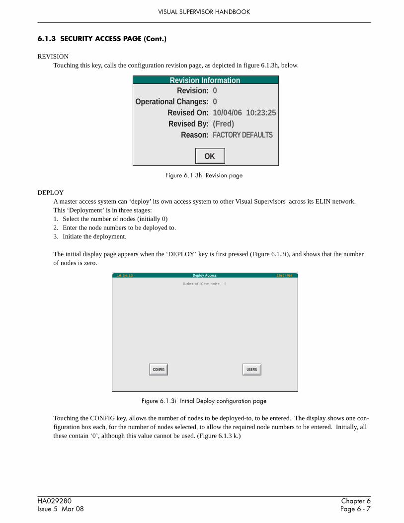
Chapter 6Page 6 - 7
HA029280Issue 5 Mar 08
VISUAL SUPERVISOR HANDBOOK
6.1.3 SECURITY ACCESS PAGE (Cont.)
REVISIONTouching this key, calls the configuration revision page, as depicted in figure 6.1.3h, below.
Figure 6.1.3h Revision page
DEPLOYA master access system can ‘deploy’ its own access system to other Visual Supervisors across its ELIN network.This ‘Deployment’ is in three stages:1. Select the number of nodes (initially 0)2. Enter the node numbers to be deployed to.3. Initiate the deployment.
The initial display page appears when the ‘DEPLOY’ key is first pressed (Figure 6.1.3i), and shows that the numberof nodes is zero.
Revision InformationRevision:
Operational Changes:Revised On:Revised By:
Reason:
0010/04/06 10:23:25(Fred)FACTORY DEFAULTS
OK
Figure 6.1.3i Initial Deploy configuration page
Touching the CONFIG key, allows the number of nodes to be deployed-to, to be entered. The display shows one con-figuration box each, for the number of nodes selected, to allow the required node numbers to be entered. Initially, allthese contain ‘0’, although this value cannot be used. (Figure 6.1.3 k.)
Number of slave nodes: 0
CONFIG USERS
Deploy Access10 ;24 :13 10 /04 /06

VISUAL SUPERVISOR HANDBOOK
Chapter 6Page 6 - 8
HA029280Issue 5 Mar 08
6.1.3 SECURITY ACCESS PAGE (Cont.)
Figure 6.1.3j Node number configuration.
Operation of the FILL key at this point will fill the node number configuration boxes with nodes 1 to n, where n is thenumber of nodes selected.
If, instead, the first node is entered by the user (say node 10), the FILL operation will automatically fill in the remain-ing node numbers, (starting at 11 in this example).
If non-consecutive node numbers are entered, say nodes 17, 3, 9, 103 and 14, then the SORT button can be used toreorder the nodes in ascending order (3, 9, 14, 17, 103).
The CLEAR key is used to reset all the mode numbers to ‘0’.
Operation of the OK key, returns to the previous page, only this time, the newly configured items appear.
Deploy Access - Config10 :26 :06 10 /04 /06
Number of slave nodes: 5
Slave nodes:
0 0 0 0 0
OK CLEAR FILL SORT
Figure 6.1.3k Completed configuration
Operation of the DEPLOY key causes the deploy to be initiated, once signed and authorized if necessary. Figure6.1.3l shows the confirmation page.
Deploy Access10 :27 :48 10 /04 /06
Number of slave nodes: 5
Slave nodes:
3 9 14 17 103
DEPLOY CONFIG USERS

Chapter 6Page 6 - 9
HA029280Issue 5 Mar 08
VISUAL SUPERVISOR HANDBOOK
6.1.3 SECURITY ACCESS PAGE (Cont.)
Figure 6.1.3l Deploy confirmation page
Number of slave nodes: 5Slave nodes:
Reason:
3 9 14 17 103
Signed byIdent:
PasswordAuthorised by
Ident:Password:
ADMIN
********
********
Confirm Action: DEPLOY
Deploy Access
OK CANCEL

VISUAL SUPERVISOR HANDBOOK
Chapter 6Page 6 - 10
HA029280Issue 5 Mar 08
6.2 ELECTRONIC SIGNATURES
6.2.1 Enabling electronic signatures
Note: Once Electronic signatures have been enabled, they can not subsequently be disabled.
As shipped, electronic signatures are disabled. The ‘Enable signatures’ Signature Configuration page (figure 6.2.1)appears on the first operation of the SIGN CONFIG key in the Administration menu.
The only choices are to quit the page (by selecting another page using the menu key) or Enable electronic signatures.
Figure 6.2.1 Enable Signatures page
When ‘Enable’ is operated, a dialogue box appears requiring two separate ADMIN passwords before the SignatureConfiguration page (figure 6.2.2) appears.
Signature Configuration10 :29 :28 10 /04 /06
The "ENABLE' button may be used to turn on electronic signatures. Once signatures have been
turned on and saved, they cannot be turned off again.
ENABLE
NET AUDIT SIGN CONFIG
Administration

Chapter 6Page 6 - 11
HA029280Issue 5 Mar 08
VISUAL SUPERVISOR HANDBOOK
6.2.2 Signature Configuration
Figure 6.2.2a shows the Signature Configuration page. The administrator IDs in ‘Revision Level’ are, initially the IDsof the administrators who enabled the Electronic Signature feature. Subsequently the IDs are those of the administra-tors who signed/authorized the previous Configuration Save.
Signature configuration10 :31 :29 10 /04 /06
SAVE DEFAULTS
Revision:
Function:
SAVE:
Account Properties:
Account Maintenance:
User Password Change:
RETIRE:
DISABLE:
ENABLE:
REINSTATE:
DEPLOY:
1 10/04/06 10:31:25 ADMIN ADMIN2
Security Access
No Confirmation
Confirm only
Signature
Sign & Authorise
Action disabled
Sign & Authorise
Sign & Authorise
Action Disabled
Signature
CANCEL
Figure 6.2.2a Signature Configuration page
ACCESS LEVELS
As can be seen from figure 6.2.2a, above, a number of instrument features can have an access level assigned to them.The possible access level definitions are as follows:
No Confirmation The instrument behaves as if electronic signatures are turned off.Confirm only A dialogue box with OK and CANCEL buttons appears, before the action is undertaken.Signature A password entry by a user with Signature Permissions is required before the action is per-
formed.Sign & Authorise A password entry by a user with Signature Permission and a further entry by a user with
authorization permission are required before the instrument will respond to the requestedaction.
Action Disabled This causes the relevant button caption to be ‘greyed out’ thus becoming inaccessible to theuser. Thus the action may not be undertaken at all.
Note: Some functions cannot be allocated some access levels. Administrative functions, for example, alwaysrequire a minimum level of ‘Signature’, and some functions cannot be assigned ‘Action Disabled’.
The available functions are in a number of categories, a picklist of categories being displayed when the ‘Function’field is touched. Figure 6.2.2b, below shows this picklist.
The button functions at the bottom of the page are as follows:
SAVE Saves all changes to all functions.CANCEL Cancels all changes made since last SAVE or DEFAULT operation.DEFAULT Returns the access levels to those when initially enabled.

VISUAL SUPERVISOR HANDBOOK
Chapter 6Page 6 - 12
HA029280Issue 5 Mar 08
6.2.2 SIGNATURE CONFIGURATION (Cont.)
Figure 6.2.2b Function picklist
Security Accessy
Security Access
Application
Setup
Cloning
File Manager
Administration
Alarms
Overview
Programmer
Recipe
Batch
Logging

Chapter 7Page 7 - 1
HA029280Issue 5 Mar 08
VISUAL SUPERVISOR HANDBOOK
CHAPTER 7: REMOTE ACCESS
The instrument provides a limited set of facilities which allow remote users to access the instruments.
7.1 FTP
7.1.1 FTP logon
FTP access always requires the user to log on. Anonymous FTP logons are not permitted. To configure the instru-ment for FTP logon, the user-based access system (section 4.4.3) must be used, and the relevant user’s attributes con-figured to include FTP = ‘Yes’.
The instrument allows up to four users to be logged in at any one time, but only one of these may have write permis-sion (attribute View Only = ‘No’). This user’s log on/ log off activity is recorded in the Event Log. Users with ViewOnly = ‘Yes’ do not have their log on/log off activity recorded.
Notes:1. Any attempt to log into a non FTP account, or into a nonexistent account will be recorded in the Event
log.2. The mis-typing of FTP passwords is included in the count of ‘failed attempts to log in’ (section 4.4.3.2),
and therefore may result in the account being disqualified.3. Attempts to login to non FTP accounts are not included in the count of ‘failed attempts to log in’.
TIMEOUTFTP users are automatically logged out after 2 minutes of inactivity. This happens regardless of any values for usertimeout which have been set at the instrument user interface.
7.1.2 File system
The file system, as viewed via FTP, is seen as a simple set of folders, with the characteristics shown in table 7.1.2.
Notes:1. It is not possible to access the USB bulk storage device via FTP.2. It is not possible to create new folders via FTP.
Table 7.1.2 File system
7.1.3 Archive File Transfer
If Review software or any other FTP client is used to transfer files from the internal archive to a PC, then it is recom-mendeda. That the user account attribute configuration includes FTP = ‘Yes’ and View Only = ‘Yes’ andb. The access level for this account be set to ‘Operator’c. The account is used only for this purpose.
/app E: Internal flash memory for application files Yes If IPRP not enabled/history H: Internal archive (if fitted) No If archive fitted
FTPName
LINdevice
DescriptionWrite
PermissionVisibility

VISUAL SUPERVISOR HANDBOOK
Chapter 7Page 7 - 2
HA029280Issue 5 Mar 08
This page is deliberately left blank

Chapter 8Page 8 - 1
HA029280Issue 5 Mar 08
VISUAL SUPERVISOR HANDBOOK
CHAPTER 8: THE CONTROL CONFIGURATOR
This chapter describes the control configurator resident in the unit. The main topics covered are:1. Overview of the configurator2. Getting ready to run the configurator3. Running the configurator4. Database configuration5. Modbus Slave Gateway configuration
8.1 OVERVIEWThe resident control configurator allows a control strategy to be set up directly within a CPU, as an alternative todownloading a configuration created in the LINtools package. The configurator can also be used to load, start, stop,and monitor databases, and to perform various filing operations. Note that with heavily-loaded running databases theconfigurator may be significantly slowed down.Configurations employ the standard LIN block-structured approach. The LIN Product Manual (Part numberHA082375U999) gives full details of the software function blocks available for strategies, and how to configure theirparameters.The configurator program itself resides in the instrument's CPU and is accessed via any telnet client program. Thechoice of serial or telnet communications must first be made in the comms setup page (section 4.5), and the user IDaccess system must be enabled and a user set up with ‘Remote’ attribute enabled (section 4.4.3).
8.2 PREPARATION
8.2.1 Configurator mode selection
Set the ENET5 port protocol to TERMCFG as described in section 4.5.1
8.2.2 Control efficiency selection
The configurator can be run at the same time that the database is running. However, this affects the control effi-ciency, in a way that depends on how the Options.CONFspd bit in the control strategy’s header block has been set.
With CONFspd TRUE, the CPU is allowed to spend up to 30% of its time updating blocks in the control strategy, andthe rest is available for serving the front panel and configurator task if running. Thus, if CONFspd is set TRUE, thecontrol strategy will not respond at full speed but the configurator can be run as often as needed without affectingperformance.
With CONFspd FALSE (the default state), and the configurator not in use, the CPU can spend up to 40% of its timeupdating blocks.

VISUAL SUPERVISOR HANDBOOK
Chapter 8Page 8 - 2
HA029280Issue 5 Mar 08
8.3 RUNNING THE CONFIGURATOR
8.3.1 Initial menu access
1. Power up all components and run Hyperterminal®. The starting screen appears, offering a selection of optionsnumbered 0 to J.
2. Type <2> to select the Enter Terminal Mode option. The Terminal Emulator screen appears.3. Press <Ctrl> + <K> to select Enter VT100 mode for T100 Configurator. (‘T100’ is the generic name of the
configurator).
Note: If the screen goes blank, press <Enter> once or twice to continue.
4. Type <1> for the ANSI-CRT option. A log-in screen appears. Once a valid user ID and password have beenentered for a user with Remote attribute enabled, the configurator Initial menu appears as depicted in figure 8.3.1.
INIT Choose option
>DATABASE - General configuration
GATEWAY - MODBUS configuration
Figure 8.3.1 Configurator initial menu
NOTE. The appearance of the Initial or Main menus indicates that the CPU has entered configuration mode.
Locate the cursor (>) at a menu item using the cursor keys, then press <Enter> to display the next level in the menuhierarchy. This is selecting an item. In general, to access the next lower level of the menu hierarchy, press <Enter>.To return to the next higher level menu or close a ‘pop-up’ options menu press the <Escape> key. <PageUp> and<PageDown> access hidden pages in long tables.
For keyboards without cursor-control keys, equivalent ‘control’ character combinations may be used, as indicated inTable 8.3.1. To use these, hold down the <Ctrl> key and type the specified character.
Function Key combinationCursor Up <Ctrl> + UCursor Down <Ctrl> + DCursor Left <Ctrl> + LCursor Right <Ctrl> + RPage Up <Ctrl> + PPage Down <Ctrl> + N
Table 8.3.1 Cursor-control — equivalent key combinations
Some tables allow values to be entered directly, or to be called-up by a menu.
For direct entry, type the first character(s) of the chosen option, followed by <Enter>.
Alternatively, access the menu with <Enter> or <Tab> as the first character after the field is selected.

Chapter 8Page 8 - 3
HA029280Issue 5 Mar 08
VISUAL SUPERVISOR HANDBOOK
8.3.2 The Initial menuThe Initial menu (Figure 8.3.1) lists two options — Database and Gateway. Select Database to access the Main menufor configuring a LIN database. This is described in section 8.4. Select Gateway to access the Gateway menu, forsetting up a Modbus configuration, described in section 8.5.
8.3.3 Quitting the VDU package & CPU configuration mode
The starting screen can be returned-to at any time while running the VDU package, by operation of <Ctrl>+<E>. Typ-ing <A> in the starting screen quits the VDU program.
Note: this action does not quit configuration mode in the CPU itself.
Getting a CPU out of configuration mode must be done from the terminal. Press <Escape> repeatedly until the mainmenu screen appears, then press <Escape> once more to clear the screen. The CPU is now out of configuration mode.
Notes1. <Ctrl>+<O> (‘Exit VT100 mode…’) does not quit CPU configuration mode and must not be pressed.2. Stop/start/download/upload files cannot be stopped via LINfiler (in the LINtools package) in a CPU if it
still in configuration mode. If any attempt is made to do so, Error 8333 (‘Configurator in use’) is reported.It is necessary to quit CPU configuration mode before such operations are attempted.
CautionAlways quit the primary CPU from configurator mode after use. Otherwise, an operator, unaware that theCPU is still in configurator mode, might subsequently plug in a terminal and type <Enter> <Enter> — hopingto see the version and power-up/shutdown messages. The result could be totally unexpected because the con-figurator would continue from its last operation. For example, if if the configurator were last used to start adatabase it would execute the start sequence (twice).
8.4 DATABASE CONFIGURATION
Figure 8.4 shows the Main menu, and sections 8.4.1 to 8.4.7 describe its items.
MAIN MENU Select option
>MAKE - Create block
COPY - Copy block
DELETE - Delete block
INSPECT - Inspect block
NETWORK - Network setup
UTILITIES - Engineering utilities
ALARMS - Current Alarms
ALARM LOG - Alarm History Log
EVENT LOG - EVENT LOG
Figure 8.4 Configurator Main menu

VISUAL SUPERVISOR HANDBOOK
Chapter 8Page 8 - 4
HA029280Issue 5 Mar 08
8.4.1 MAKE
Installs function blocks in the control strategy. Note that a running database must be stopped before any blocks can beadded to it. (Stopping and starting the database is described in section 8.4.6.) Select MAKE to display the SETMENU — the controller’s resident library of block categories, detailed in the LIN Product Manual (Part numberHA082375U003). Note that every strategy must contain a ‘header’ block (Eycon-10 or Eycon-20) the only blockinitially available for a new strategy. Select a category to list its blocks. Figure 8.4.1a shows part of the screen dis-play when LOGIC is selected, as an example.
LOGIC Select type
>PULSE
AND4
OR4
XOR4
Figure 8.4.1a Logic category menu (upper part)
Select the block to be installed. The block Overview appears listing the block parameters, default values and units ina double 3-column format. Figure 8.4.1b shows the (default) overview for the PID block as an example.
BLOCK OVERVIEWRefer to Figure 8.4.1b which shows the main features of a typical block overview, used to monitor and update blockparameters. (Overviews can also be accessed via the COPY and INSPECT main menu options.) The overview isequivalent to a LINtools Specification menu and its fields have the same meanings, although data entry is different.
Note : Parameters being updated by incoming connections from other blocks are not specially indicated in ablock overview.
OVERVIEW Block: “NoName” Type: PID Compound:
Mode AUTO Alarms
FallBack AUTO
HAA 1ØØ.Ø Eng
PV Ø.Ø Eng LAA Ø.Ø Eng
SP Ø.Ø Eng HDA 1ØØ.Ø Eng
OP Ø.Ø % LDA 1ØØ.Ø Eng
SL Ø.Ø Eng
TrimSP Ø.Ø Eng TimeBase Secs
RemoteSP Ø.Ø Eng XP 1ØØ.Ø %
Track Ø.Ø % TI Ø.ØØØ
TD Ø.ØØØ
HR_SP 1ØØ.Ø Eng
LR_SP Ø.Ø Eng Options ØØØØ11ØØ
HL_SP 1ØØ.Ø Eng SelMode ØØØØØØØØ
LL_SP Ø.Ø Eng
ModeSel ØØØØØØØØ
HR_OP 1ØØ.Ø % ModeAct ØØØØØØØØ
LR_OP Ø.Ø %
HL_OP 1ØØ.Ø % FF_PID 5Ø.Ø %
LL_OP Ø.Ø % FB_OP Ø.Ø %
Figure 8.4.1b Overview — PID block

Chapter 8Page 8 - 5
HA029280Issue 5 Mar 08
VISUAL SUPERVISOR HANDBOOK
8.4.1 MAKE (Cont.)
BLOCK OVERVIEW (Cont.)
Title bar. Contains fields common to all overviews: Block, Type, and Compound. Block and Type havetheir usual LIN meanings; Compound is equivalent to Dbase. Please refer to the LIN BlocksReference Manual (in the LIN Product Manual) for details of these fields. A blank Compoundfield denotes that the block database is local.Note that the block is not installed into the control strategy until (at the minimum) its Blockfield has been assigned a value — i.e. tagname — and the database has been restarted.
Overview data field entry. To update a parameter field, locate the flashing ‘underline’ cursor (_) at the field using thearrow keys, then proceed as described below for the different data field types. Some datafields display further nested levels of data when entered. In such cases, press <Enter> toaccess a deeper level; press <Escape> to return to a higher level.Note that editing a database during runtime is possible but is not recommended. (Stopping thedatabase is described in section 8.4.6, below)
User-defined names. Type in a name (8 characters max.) and press <Enter> to overwrite existing data. To insertcharacters, locate the cursor at the character to follow and type the insertions. A ‘beep’ warnsthat excess characters have been typed. To abort the current entry and leave the databaseunchanged, move the cursor to a field above or below the current field before pressing <En-ter>, or press the <Escape> key.Note that, remote database names entered in the Compound field must be prefixed by an‘equals’ sign (=) which is included in the character count.Pressing <Enter> with the cursor on the first character of the Block or Compound fields(before starting to type) accesses a Full Description page (Figure 8.4.1c shows an example).This page gives general information about the block and has a common format.
FULL DESCRIPTION Block: PID_1 Type: PID
Refresh rate Ø.1Ø4Ø
Server number 2
Compound: =Alpha
Rate ms
Figure 8.4.1c FULL DESCRIPTION page for block (example)
Block. (Read/write). Block tagname.Type (Read-only). Block type.Refresh rate. (Read-only). Time (secs) since the block was last scheduled to run. Note
that for a control block the PID algorithm is not necessarily recalculatedevery time the block is scheduled.
Server number (Read-only).Compound. (Read/write). Name of the block’s parameter database. A blank field means
the block database is local, i.e. in the current Controller/Supervisor. (Data-base names and their LIN addresses are specified via the main menu NET-WORK option, described in section 8.4.5.)
Rate ms. Rate is the minimum update period (i.e. maximum rate) at which an indi-vidual cached block is transmitted across the Local Instrument Network(LIN). The default is 10ms minimum, i.e. 100Hz maximum. Rate can be setbetween 10ms and 64s. Note that rate values are minimum update timesonly, and heavily loaded networks may not be able to reach the faster updaterates.

VISUAL SUPERVISOR HANDBOOK
Chapter 8Page 8 - 6
HA029280Issue 5 Mar 08
8.4.1 MAKE (Cont.)
Parameter values. Type in a value and press <Enter> to update the database. (Read-only parameters do notaccept new values.) The CPU automatically adds a following decimal point and padding zerosif needed, but before a decimal point a zero must always be typed, e.g. 0.5, not .5.Pressing <Enter> with the field selected, before starting to type, accesses a Full Descriptionpage for the parameter (Figure 8.4.1d shows an example).
FULL DESCRIPTION Field: PV Block: PID_1 Type: PID
Value 8Ø.1 Real32
Input SIM 1.OP
Figure 8.4.1d FULL DESCRIPTION page for parameter (example)
Field, Block, Type. Read-only fields.Value. (Read/write) Parameter value, editable as for the Overview.Real32. (Read-only) Value type (Real32 = floating point number)Input. (Read/write) Defines the source of any connection to the parameter from anotherblock, as Block Tagname.Output Mnemonic. A blank field means no connection. To make oredit a connection, type in the source block tagname and output mnemonic (e.g. SIM 1.OP, orSEQ.DIGOUT.BIT3), then press <Enter>. Invalid data is ‘beeped’ and is not accepted. Thefield is not case sensitive. To delete a connection, type <space> then press <Enter>.
NOTE. See below for information and advice on types of database connections.
Parameter units. Type in a value and press <Enter>. All other related units in the database automatically copythe edited unit. Pressing <Enter> with the field selected, before starting to type, accesses theparameter Full Description page (as for the value field).
Options menu fields. Press <Enter> to display a pop-up menu of options for the field. Figure 8.4.1e shows anexample (PID Mode) in part of an overview page.
OVERVIEW Block: PID_1 Type: PID Compound:
Mode Alarms
Fallback >HOLD
TRACK HAA 1ØØ.Ø Eng
PV MANUAL g LAA Ø.Ø Eng
SP AUTO g HDA 1ØØ.Ø Eng
OP REMOTE LDA 1ØØ.Ø Eng
SL F_MAN g
TrimSP F_AUTO g TimeBase Secs
RemoteSP g XP 1ØØ.Ø %
Track TI Ø.ØØØ
TD Ø.ØØØ
Figure 8.4.1e Pop-up options menu (example)
Using the ‘arrow’ keys, move the cursor (>) to a menu option and select it by pressing <En-ter>. (Disabled options may not respond to selection.)A quicker alternative to accessing the pop-up options menu is to type the required option, orenough of its initial letters to uniquely specify it, directly into the selected field and then press<Enter>. E.g. entering just H selects HOLD; entering F_M selects F_MAN (Forced Manual).

Chapter 8Page 8 - 7
HA029280Issue 5 Mar 08
VISUAL SUPERVISOR HANDBOOK
8.4.1 MAKE (Cont.)
Alarms field Press <Enter> to display a 4-column Alarms page listing alarm name (e.g. HighAbs), acknowl-edgement (e.g. Unackd), status (e.g. Active), and priority (0 to 15). Update the acknowledge-ment or priority fields (the only editable ones) by typing in a value and pressing <Enter>.(Any single letter can be used for the acknowledgement field.) Figure 8.4.1f, below, shows anexample Alarms page.
Alarms Block: PID_1 Type: PID
Software Unackd Active 15
HighAbs Unackd Active 15
LowAbs Ø
HighDev Active 1Ø
LowDev 2
Combined Unackd Active 15
Figure 8.4.1f Alarms page (example)
Bitfields Contain eight (or sixteen) binary digits showing the logic states of a corresponding set of up toeight (or sixteen) parameters. To edit the bitfield directly, type in a bit-pattern then <Enter> it.Alternatively, press <Enter> to display a Full Description page listing the parameter TRUE/FALSE or HIGH/LOW states (in the same format used for LINtools Specification Menubitfields). Figure 8.4.1g shows an example. Alter a logic state by locating the cursor on thestate, typing in T(rue) or F(alse), and pressing <Enter>. (A bit may be read-only.)
FULL DESCRIPTION Field: ModeAct Block: PID_1 Type: PID
NotRem TRUE
HoldAct FALSE
TrackAct FALSE
RemAct FALSE
AutoAct TRUE
ManAct FALSE
FAutoAct FALSE
FManAct FALSE
Figure 8.4.1g FULL DESCRIPTION page for bitfield (example)
To connect an input to a bitfield, press the Æ key and type in the block name/field name fromwhich the connection is to be made.
Note: See below for information and advice on types of database connections.
Two- and four-digit ‘combined’ hexadecimal status fields.Hex fields are marked with a ‘>’ sign and have the same format and significance as thosefound in LINtools specification menus. The digits show the logic states of a corresponding setof parameters, up to four per hex digit. To edit the field directly, type in new values then press<Enter>. Alternatively, press <Enter> to display a Full Description page listing the parameterTRUE/FALSE states and edit this list (as described for Bitfields, above).

VISUAL SUPERVISOR HANDBOOK
Chapter 8Page 8 - 8
HA029280Issue 5 Mar 08
8.4.1 MAKE (Cont.)
CONNECTION TYPES IN A CPU DATABASEThere are three types of connection used in a CPU database: local connections, connections writing to a cachedblock, and connections from a cached block to a local block. The following explains how and when they are evalu-ated.1. Local connections. These are connections between two blocks that are both local to the CPU database. The
connection is always evaluated immediately prior to the execution of the destination block’s update procedure,regardless of whether the source data has changed between iterations. With this sort of connection, any attemptto write to the connection destination is immediately ‘corrected’ by the next connection evaluation.
2. Connections writing to cached block. These are connections whose destination block is a cached copy of ablock in another instrument. The source of the connection can be either a local database block or another cachedblock. Such connections are evaluated only if the source and destination data do not match. All cached blocks inthe database are processed at regular intervals, and whenever a change is detected a single field write is per-formed over the communications link.
3. Connections from cached block to local block. These are connections where the source block is a cached copyof a block in another instrument, and the destination block is local to the CPU database. All cached blocks in thedatabase are tested at regular intervals, and if a change in the block data is detected, then all such connections outof the cached block into local blocks are evaluated. The connections are not evaluated if the source data has notchanged.
8.4.2 COPY
Creates duplicates of existing blocks. Select COPY from the main menu to display all the blocks in the control strat-egy, in semi-graphical format as shown in Figure 8.4.2. The blocks are displayed from left to right in order of crea-tion. Move the cursor (>) to a block and press <Enter>. The block is duplicated and added to the strategy, and itsOverview page automatically appears ready for parameterising. The duplicate retains all the original parameter valuesexcept for the Block field, which has the default tagname “NoName”. Input connections are not copied; nor are I/Oblock site numbers.
COPY Select block
Root SIM_1 TIC_100 PID_1 FIC_101
Figure 8.4.2 COPY display (example)
Pressing <Escape> returns the COPY display, where the copied block can be seen added to the list. Press <Escape>again to return to the top level menu.
8.4.3 DELETE
Deletes blocks from the control strategy. (Note that the control database must be halted, otherwise selecting DELETEresults in a warning ‘beep’ and no action. Stopping the database is described in the UTILITIES option described insection 8.4.6. Also, a block cannot be deleted unless its input connections have been cleared.) Select DELETE fromthe main menu to display all the blocks in the control strategy, in the same format as for the COPY option described insection 8.4.2. Select a block and press <Enter>. The block and any connections from it are deleted, and the mainmenu returns to the screen.

Chapter 8Page 8 - 9
HA029280Issue 5 Mar 08
VISUAL SUPERVISOR HANDBOOK
8.4.4 INSPECT
Allows blocks in the control strategy to be inspected and updated. Select INSPECT from the main menu to display allthe blocks in the control strategy, in the same format as for the COPY and DELETE options already described. Selecta block and press <Enter> to display its overview page, ready for monitoring/updating.Pressing <Escape> returns the INSPECT display, where other blocks can be selected for inspection. Press <Escape>again to return to the top level menu.
8.4.5 NETWORK
Allows block databases to be assigned names and node addresses on the LIN (Local Instrument Network) so that theycan be configured as ‘cached’ blocks and run in a remote instrument. (The cached block’s Compound field, in itsoverview page, specifies the remote database name.)
Note: It is good practice when using cached blocks, always to cache at least one block in each direction. Thisenables the status of the comms link between the nodes to be monitored from both ends — via the cachedblocks’ software alarms.
Select NETWORK from the main menu to display the Network setup page (initially blank). Figure 8.4.5 shows thetop part of an example page with several databases already assigned.
Network setup
Alpha >Ø1
Beta >Ø2
dBase_1 >Ø3
Figure 8.4.5 NETWORK setup page (example)
To assign a new database name and address, locate the underline cursor at the left hand column of a blank row, type ina unique name (7 characters max.) and press <Enter>. The name appears added to the list together with a default nodeaddress >ØØ. (Non-unique or invalid names are ‘beeped’ and not accepted. Do not use ØØ or FF as node ad-dresses). Move the cursor to the default address and type in the required node address (two hex digits). Press <En-ter> to complete the assignation.
To edit an existing name or address, locate the cursor at a field, type in the new value, and press <Enter>. Invalidentries are not accepted.
To delete a complete name and address entry, edit its name field to a space character. Configurations downloadedfrom LINtools (or Eurotherm Network) will have a Network page set up automatically.

VISUAL SUPERVISOR HANDBOOK
Chapter 8Page 8 - 10
HA029280Issue 5 Mar 08
8.4.6 Utilities
Allows program control, I/O calibration, and filing. Select UTILITIES from the main menu to display the Utilitiesoptions, shown in Figure 8.4.6.
UTILITIES Select option
>START - Start runtime system
STOP - Stop runtime system
SAVE - Save database
LOAD - Load database
FILE - File page
CALIBRATE - Calibrate IO Sites
Figure 8.4.6 UTILITIES options menu
START, STOP UTILITIESSelect START or STOP from the UTILITIES options menu and press <Enter> to start or stop the control programrunning in the local Controller/Supervisor.
Note: When a database is started in RAM it is automatically saved to the file in FLASH calledfilename.DBF, where filename is indicated in the filename.RUN file. It is then reloaded from FLASH toRAM and started.
SAVE UTILITYNames and saves a control program to a specified memory area. Select SAVE from the UTILITIES options menu —the default filename specification, E:Eycon_10.DBF* is displayed. (The prefix E: directs the save to the CPU’sFLASH area; this is the only available memory area. To save a database to a remote instrument, prefix the filenamespecification by the node address of the instrument separated by a double colon, e.g. FC::E:Eycon_10.DBF*).Type in a new specification if needed, then press <Enter> to execute the save. After a short pause the CPU signalscompletion with the message: ‘Type a key to continue’. Typing any key returns the UTILITIES menu.An invalid filename specification aborts the save, and the CPU sends an error message, e.g. ‘Save failed — Invaliddevice’.
Notes:1 Please refer to the note in section 8.4.6 about automatic saves.2 Modifications to a control database are carried out on the RAM image only, not directly to the .DBF file
in FLASH. They are copied to FLASH (overwriting the existing .DBF file) automatically when thedatabase is restarted, or when a SAVE operation is carried out .
LOAD UTILITYRetrieves a control program from a specified memory area and loads it to the CPU RAM area. Note that LOAD can-not be performed during runtime. Select LOAD from the UTILITIES options menu — the default filename specifica-tion, E:Eycon_10.DBF* is displayed. Edit the specification if needed (to alter the filename or its source, as describedfor the SAVE utility above), then press <Enter> to execute the load. After a short pause the CPU signals completionas described for the SAVE option. Typing any key returns the UTILITIES menu.
An invalid filename specification aborts the load, and the CPU sends an error message, e.g. ‘Load failed — File notfound’. To load a file from a remote node, prefix the filename by the address of the remote node e.g.FC::M:FRED.DBF.
* or Eycon_20.DBF, according to model.

Chapter 8Page 8 - 11
HA029280Issue 5 Mar 08
VISUAL SUPERVISOR HANDBOOK
8.4.6 UTILITIES (Cont.)
FILE UTILITYPermits access to the CPU file page, allowing files to be deleted or copied, and the E: device to be formatted. The filepage displays files in the E-device and also in a configurable remote ??::?: device. To access a remote device, movethe cursor to the ??::?: field and type in the required node and device letter, e.g. FA::M:. Press <Enter> to display itsfiles (up to a maximum of 20).
Move the cursor up and down the file list and tag files with an asterisk (*) using the <Enter> key. Then move thecursor to the top column-head field and press <Enter> to display the function menu: Copy, Delete, Find, and — for E-device and A-device only — Format. Finally, select a function and press <Enter> to carry it out. (Note that the Findfunction has wild-card characters (?) which help in the locating of filenames containing known character strings.)Press <Escape> to return to the UTILITIES menu.
8.4.7 ALARMS
Select ALARMS to view the currently active alarms in the instrument. Move the cursor up and down the list; press<Enter> to acknowledge an individual alarm. Press I to inspect the block containing the alarm.
8.4.8 ALARM LOG
Select ALARM LOG to view a reduced-functionality version of the front panel alarm history.
8.4.8 EVENT LOG
Select EVENT LOG to view a reduced-functionality version of the front panel event history.

VISUAL SUPERVISOR HANDBOOK
Chapter 8Page 8 - 12
HA029280Issue 5 Mar 08
8.5 MODBUS CONFIGURATION
Note: The resident Modbus configurator is similar in operation to the Modbus configurator in the T500LINtools package. See the T500 LINtools Product Manual (Part No. HA082377U999) for more informa-tion.
GATEWAY MODBUS configuration
-------------------------------------------------------------
>GWindex - Select GW index
MODE - Operating mode
INTERFACE - Select interface
SETUP - Serial line
TABLES - Register & bit configuration
Figure 8.5 Gateway menu
8.5.1 GW indexThis command appears only for products which support multiple GW indices.
Select the GW index number ( 1 to 3 inclusive) that is to be viewed by the configurator. The filename (where the GWindex number was loaded) appears in the filename field.
GWindex Select GW index
-------------------------------------------------------------
GWindex 1
Filename Filename
8.5.2 MODE
Selecting MODE causes a pop-up menu to appear, allowing the user to select Master or Slave mode. The selectedmode is arrowed.
MODE Operating mode
-------------------------------------------------------------
Mode +--------+
|>Slave |
| Master |
+--------+

Chapter 8Page 8 - 13
HA029280Issue 5 Mar 08
VISUAL SUPERVISOR HANDBOOK
8.5.3 INTERFACEAllows the interface type and instance of the instrument to be selected. The Interface type should be selected as Serialor TCP/Ip, then the port number to which the Modbus instrument is to be connected should be entered.
INTERFACE Select interface
-------------------------------------------------------------
+--------+
Type Serial|>Serial |
COM1 | TCP/IP |
+--------+
8.5.4 SETUP
Configures the selected Interface Type and Interface Instance of the instrument defined in the INTERFACE menu.Selecting SETUP displays a menu that is dependent on the INTERFACE and MODE configurations.
SERIAL MASTERIf Serial is selected in the INTERFACE menu and Master is specified in the MODE menu the SETUP menu showsBaud rate, Parity, Stop bits, and Time out fields.
SERIAL SLAVEIf Serial is selected in the INTERFACE menu and Slave is specified in the MODE menu the SETUP menu showsBaud rate, Parity, Stop bits, Time out, and Slave No. fields.
SETUP Configure interface
Baud rate 2400
Parity Odd
Stop bits 2
Instr No >63
Time out 1.000 secs
TCP MASTERIf TCP/IP is selected in the INTERFACE menu and Master is specified in the MODE menu the SETUP menu showsonly the Time out field.
TCP SLAVEIf TCP/IP is selected in the INTERFACE menu and Slave is specified in the MODE menu the SETUP menu will showthe Port no, Instr No, Time out, and CNOMO fields.
Note. If the instrument supports CNOMO registers, this field indicates that Register Offset values 121, to 124will display specific Manufacturer and Product details.

VISUAL SUPERVISOR HANDBOOK
Chapter 8Page 8 - 14
HA029280Issue 5 Mar 08
8.5.4 SETUP COMMAND (Cont.)
This page gives general information about the Interface configuration.
Port no TCP/IP Interface and Slave Operating Mode only. It shows the TCP port via which this modbus-TCP-slave instance communicates. 0 = default = 502.
Baud rate Highlight and enter this item to see a menu of the available baud rates, 110, 150, 300, 600, 1200, 2400,4800, 9600, and 19200. Select and enter the required baud rate.
Parity Entering this item displays a menu of options, None, Odd, and Even. Select and enter the required parity.Stop bits Enter this item, type in the required number of stop bits, and press <Enter> to update the SETUP menu,
Only 1 or 2 stop bits are permitted.Line type Shown only if both Serial Interface is selected and the instrument supports software selection of 3-wire/5-
wire operation.
Note. This is not currently supported.
Time out Enter a Time out value, in the range 0 to 65.5 seconds. In slave mode, this parameter specifies a watchdogperiod for all tables. That is, if a table has not been accessed for Time out seconds, the Online bit in theslave mode diagnostic register for that particular table resets to zero. In master mode, Time out specifies amaximum period between the end of a master’s request for data to the start of the slave’s response. If thistime is exceeded, the Online bit in the master mode diagnostic register for the particular table concernedresets to zero.
Instr No Slave Operating Mode only. Input an ‘instrument number’, i.e. the address on the Modbus Serial link ofthe slave device being configured. Slave addresses are in the range 01 to FF hexadecimal, but note thatfor some equipment FF is invalid.

Chapter 8Page 8 - 15
HA029280Issue 5 Mar 08
VISUAL SUPERVISOR HANDBOOK
8.5.5 TABLES
Shows the Tables List dependant on the MODE configuration. To view the tables list, highlight TABLES and press<Enter>. Individual menus can be displayed by selecting the required Table number, see Table Menus.
TABLES LISTThe Tables List provides an overview of all the tables in the Modbus configuration. Each instrument supports a maxi-mum number of Tables as defined by the MAX_TABLES field in the instrument Configuration (Header) block. TheTables List offers sixteen tables, so 4 pages are used to cover the 64 tables.
This menu allows tables to be created and the types, offsets, sizes, and for master mode, function codes, scan counts,instrument numbers and tick rate to be specified. The Tables List also accesses individual Table Menus for detailedconfiguration, i.e. LIN Database mapping, see Table Menus section.
The Tables List menu below shows an example Tables List with Table 1 configured as a Register Table. The firstfour columns, Table, Type, Offset, and Count, are common to both the Master and Slave Operating Modes. The re-maining, Functions, Scan count, Instr No, and TickRate appear only when Master Operating Mode is configured.
Table Type Offset Count Functions Scan count Instr No TickRate-----------------------------------------------------------------------
1 Register 0 16 3 4 6 16 16 >00 100 2 Unused 0 0 - - - - 0 >00 0 3 Unused 0 0 - - - - 0 >00 0 4 Unused 0 0 - - - - 0 >00 0 5 Unused 0 0 - - - - 0 >00 0 6 Unused 0 0 - - - - 0 >00 0 7 Unused 0 0 - - - - 0 >00 0 8 Unused 0 0 - - - - 0 >00 0 9 Unused 0 0 - - - - 0 >00 0 10 Unused 0 0 - - - - 0 >00 0 11 Unused 0 0 - - - - 0 >00 0 12 Unused 0 0 - - - - 0 >00 0 13 Unused 0 0 - - - - 0 >00 0 14 Unused 0 0 - - - - 0 >00 0 15 Unused 0 0 - - - - 0 >00 0 16 Unused 0 0 - - - - 0 >00 0
This page gives general information about the Modbus Table configuration.Table This is the Table number, which is not editable. Highlight and <Enter> a Table number field to display
the information related to the selected Table number. For a table with a Type other than Unused, the tablemenu for that table is displayed, see Table Menu.
Type This field, defaults to Unused, allows the Table Type to be created or edited. Enter a Type field to see amenu of four options. Select one and press <Enter> to create a new table or convert an existing one to anew type.
Note. Other fields in the Tables List associated with the selection automatically adopt default values.
The Type options are:Unused The table does not exist.Register This type of table maps LIN Database parameters to standard 16-bit Modbus registers.Digital This type of table maps LIN digital, boolean or alarm values to bits in the Modbus
address space.Diagnostic This is a special table, similar to a Register Table, but the values in the table have
pre-defined values that are used to control the Modbus operation, or present diagnosticinformation to the LIN Database.

VISUAL SUPERVISOR HANDBOOK
Chapter 8Page 8 - 16
HA029280Issue 5 Mar 08
8.5.5 TABLES (Cont.)
Offset This field selects the start address of the table on the Modbus network. These values are theactual values used in the address field of the Modbus messages, i.e. the ‘protocol addresses’.
Note. PLCs differ in the correspondence between their register or bit addresses and the protocol addresses.
Count This field shows the number of registers or bits in a table. It allows the size of register anddigital tables to be changed from their default values of 64 registers or bits, respectively, tooptimise the use of memory. Diagnostic tables are fixed at 32 registers.
Functions Master mode only. This field allows the default Modbus function codes that can be used witha particular Modbus table type to be enabled or disabled. Modbus function codes define thetype of data exchange permitted between Master and Slave instruments via a particular table.To disable a default function code, highlight it with the mouse and press <Enter> to see amenu of ‘-’ and the default code number. Selecting and entering ‘-’ disables that code for thetable concerned. Select the code number again to re-enable it if required.
Scan count Master mode only. This sets the maximum number of registers (register table) or bits (digitaltable) that can be read or written in a single Modbus transmission. Scan count defaults to thesame value as Count, i.e. as the table size, which results in the whole table being updated eachpolling cycle. If Scan count is made less than Count for a particular table, it takes more thanone cycle to be updated but the overall polling cycle speeds up. This may be required forModbus devices with limited buffer sizes.
Instr No Master mode only. This specifies the hexadecimal Slave number value of the instrument onthe Modbus network in which the data registers or bits associated with this master table arelocated.
Tick Rate Each table of registers is assigned a Tick Rate, a value between 0 and 65535 ms, to define thefrequency at which it is scanned. The Tick Rate associated with each table can be configured.If the LIN instrument does not support Tick Rates, and/or if the instrument is configured tooperate in Slave mode, the Tick Rate fields are disabled.

Chapter 8Page 8 - 17
HA029280Issue 5 Mar 08
VISUAL SUPERVISOR HANDBOOK
8.5.5 TABLES (Cont.)
TABLE MENUS
Individual table menus are accessed from the tables list by highlighting of its table number (in the first column headedTable) followed by <Enter>. To highlight fields, the arrow cursor is moved around the table menu using the mouse, orthe PC’s <Home>, <End>, and cursor keys can be used.
Table menus allow the mapping between the LIN database fields and the Modbus addresses to be configured.Figure8.5.3b shows a typical default table menu for a register table.
Note that table headings differ for register and digital tables, but that some fields are common to both —Field, DB Write, and MOD Write.
Register Field DP Format DB Write MOD Write Value
------------------------------------------------------------
0 0 Normal Enable Enable >0000
1 0 Normal Enable Enable >0000
2 0 Normal Enable Enable >0000
3 0 Normal Enable Enable >0000
4 0 Normal Enable Enable >0000
5 0 Normal Enable Enable >0000
6 0 Normal Enable Enable >0000
7 0 Normal Enable Enable >0000
8 0 Normal Enable Enable >0000
9 0 Normal Enable Enable >0000
10 0 Normal Enable Enable >0000
11 0 Normal Enable Enable >0000
12 0 Normal Enable Enable >0000
13 0 Normal Enable Enable >0000
14 0 Normal Enable Enable >0000
15 0 Normal Enable Enable >0000
Figure 8.5.3b Register table menu — default
Register (Register and diagnostic tables only) This column shows the Modbus address of the particular register. Thefirst register in the table takes its address from the Offset value given to the table via the table list (describedabove). The remaining (read-only) addresses follow on consecutively.
Digital (Digital tables only) This column shows the Modbus address of the digital bit on the selected line of the table.If the line contains a bitfield rather than a single bit, the address shown is that of the first bit in the bitfield.Mappings may be made for a single bit, or for an 8- or 16-bit field, according to the value defined in theWidth parameter (see later). The first bit address in the table takes its value from the Offset given to the tablevia the table list. The remaining (read-only) addresses follow on, according to the numbers of bits on eachsuccessive line of the table (1, 8, or 16).
Field. This is the LIN database field to which the Modbus address is mapped, or it can be left blank. Select a fieldwith the cursor and type in and enter a LIN function block name plus parameter (and subfield if needed),separated by full stops (periods), e.g. PV1.Alarms.Software.
Notes:1. If an attempt is made to enter an analogue parameter into a digital table Field, the entry is ignored. Any
type of parameter can, however, be typed into a register (or diagnostic) table.2. In a digital table, LIN database parameters cannot be entered or overwritten if to do so would force an
entry lower down the table to change its address.

VISUAL SUPERVISOR HANDBOOK
Chapter 8Page 8 - 18
HA029280Issue 5 Mar 08
8.5.5 TABLES (Cont.)
DP. (Register and diagnostic tables only) This column can be used either to specify a decimal point position, or tocreate a 32-bit register.1. Decimal point position. DP can store a decimal point scaling factor that is used when converting floating
point numbers to 16-bit Modbus registers. For this purpose, enter an integer from 0 to 4; the DP-valuerepresents the number of decimal places in the converted number.
2. 32-bit register. (Register tables only) A 32-bit register is created by ‘joining’ a consecutive pair of 16-bit registers, as described below. The following restrictions are applied to ensure that the 32-bit valuecreated is transferred indivisibly:
a The multiread function (3) and multiwrite function (16) must both be enabled.b The scan count must be even.c The first register of the pair must be at an even offset within the table.d The first register of the pair must not be the last register in the table.e The second register of the pair must not already be assigned to a LIN database field.f The field type of the 32-bit register pair must be a 32-bit long signed or unsigned, a 32-bit real or a
string. For a string, only the first four characters are transferred.To create a 32-bit register pair, enter ‘d’ (or ‘D’) in the DP field of the first register of the pair. This causes theregister’s DP to adopt the value ‘D’, and the following register the value ‘d’. If any of the above restrictionsare violated, the entry will be rejected.When the first register of the 32-bit pair is assigned to a LIN database field, the second register automaticallycopies the same field name; assigning the name and the DP can be done in either order. A 32-bit register paircan be restored to individual 16-bit registers by changing the DP of the first register to zero to four.
Format (Register and diagnostic tables only) This column specifies the format of the data in the register — normal orbinary coded decimal (BCD). Normal format means that the data is a simple 16-bit integer. In BCD formatthe value is first limited to the range 0 to 9999, and then stored as four 4-bit nibbles in the register. The unitsare stored in the low order nibble, the tens in the second nibble, the hundreds in the third, and the thousands inthe high-order nibble. BCD format allows the data to be used with certain devices such as displays.
NOTE. Format is ignored in 32-bit registers.
Width (Digital tables only) This column indicates the number of bits contained in the associated field. The defaultWidth is 16, but it automatically updates when a parameter is allocated to the field. Allocated field ‘widths’are read-only, but the width of an unallocated field can be specified by highlighting its Width value andentering a valid number in the range 1 to 16, (normally 1, 8, or 16).
Note Width values cannot be edited, if to do so would force an entry lower down the table to change itsaddress (Digital value).
DB Write This column allows selected values in the LIN database to be protected against being overwritten by valuesreceived across the serial link. Highlight the required DB Write field and press <Enter> to see a menu ofoptions — Enable and Protect. Select ‘Protect’ to write-protect the LIN database parameter, or ‘Enable’ toallow overwriting.
NOTE. For a 32-bit register pair, DB Write applies only to the first register. The DB Write-value of thesecond register is ignored.

Chapter 8Page 8 - 19
HA029280Issue 5 Mar 08
VISUAL SUPERVISOR HANDBOOK
8.5.5 TABLES (Cont.)
MOD Write This column allows selected values in the LIN database to be prevented from being written to their associatedModbus registers or bits. Highlight the required MOD Write field and press <Enter> to see a menu of options— Enable and Protect. Select ‘Protect’ to write-protect the Modbus register/bit(s), or ‘Enable’ to allowoverwriting.
Notes:1. To protect an entire table (for a Modbus Gateway facility operating in Master mode), the write function
codes 5 and 15, or 6 and 16 can be disabled in the tables list.2. For a 32-bit register pair, MOD Write applies only to the first register. The MOD Write-value of the
second register is ignored.
Value This column shows the current 16-bit value of the field in 4-digit hexadecimal representation. ‘Value’ is read-only.

VISUAL SUPERVISOR HANDBOOK
Chapter 8Page 8 - 20
HA029280Issue 5 Mar 08
This page is deliberately left bank

Chapter 9Page 9 - 1
HA029280Issue 5 Mar 08
VISUAL SUPERVISOR HANDBOOK
CHAPTER 9: PREVENTIVE MAINTENANCE
This section shows how to replace the battery and how to calibrate the touch screen.
9.1 BATTERY REPLACEMENT
The battery replacement period depends on the cumulative length of time over which the instrument is left withoutsupply power. The battery maintains the real-time clock and SRAM data (e.g. hot start database). A flag (BadBatt)can be set in the “Eycon-10 or Eycon-20” block. This flag will result in an instrument alarm should the battery volt-age falls below the minimum necessary for it to function properly. It is recommended that the battery be replaced assoon as possible after the appearance of this warning.
CautionThe user must be at the same electrical potential as the instrument housing when accessing the battery.
Notes:1. All battery backed RAM data is lost during battery change unless power to the unit is maintained during
the change.2. Battery type is BR2330 Poly-carbonmonofluoride/lithium. Available from the Visual Supervisor manu-
facturer under part number PA261095.3. Dispose of exhausted batteries in accordance with local regulations regarding this battery type.
9.1.1 Replacement procedure1. For non-Profibus units, remove the screw securing the access cover. Remove the cover. Replace the battery and
refit the cover.2. For units fitted with the Profibus option, remove the screw securing the Profibus enclosure. Carefully separate
the enclosure from the instrument, taking care not to damage the wire harness which connects the option board tothe main board. Replace the battery and refit the enclosure.
Access cover,or Profibus enclosure
Figure 9.1aAccess cover/Profibus enclosure location - large frame unit
Figure 9.1b Battery location - small frame unit(Access cover/Profibus option removed)
Note: Drawings not to the same scale
BR2330
Cover retainingscrew location

VISUAL SUPERVISOR HANDBOOK
Chapter 9Page 9 - 2
HA029280Issue 5 Mar 08
9.2 TOUCH SCREEN CALIBRATION
This procedure ensures that the instrument responds to the exact point that has been touched by the user.
At switch-on, continuously hold a finger in contact with the display screen until the 'calibration display' appears (ap-proximately 60 seconds after switch on) as depicted in figure 9.2.
Using a soft, small diameter item (e.g. a pencil point) which will not damage the touch screen, touch the intersectionof the upper set of crosshairs, as requested by the display.
Once the top left target has been accepted, continue as requested by the display. Once all the targets have been ac-cepted, initialisation continues as normal.
Touch Target
Figure 9.2 Initial calibration display screen

Chapter 10Page 10 - 1
HA029280Issue 5 Mar 08
VISUAL SUPERVISOR HANDBOOK
CHAPTER 10: PROFIBUS MASTER OPTION
10.1 INTRODUCTIONThis option provides GW Profibus Master functionality. The option circuit board and associated 9-way D-type con-nector are housed in a rectangular enclosure located at the rear of the instrument. This chapter provides electrical andmechanical details for the option and also describes how to access the Profibus Master Configuration page inLINtools.
Details of recommended Profibus network wiring are to be found in the Modbus/Profibus communications handbook(HA028014).
Configuration of the Profibus network is carried out using the Profibus editor within LINtools. To display the con-figuration page (figure 10.1):1. Click on ‘Add...’2. In the pop-up dialogue box that appears, click on ‘New LIN Profibus Master’. This adds the GWProfM_CON
block (section 10.3) to the database, and creates a Profibus Network.3. Click on the Profibus master symbol in the Contents Pane to display the Profibus Master Editor page.
Once configuration is complete, it should be saved. The Save operation automatically generates .gwf and .upb fileswhich are added to the ‘download list’. The next Download operation transfers the download list contents to the Pro-fibus Master instrument. See the on-line help file included with LINtools for further details.
Figure 10.1 Profibus editor master configuration page example
10.2 INSTALLATION
10.2.1 Mechanical installation
Figures 10.2.1a and 10.2.1b show the mechanical installation details for the small frame and large frame units respec-tively. See also chapter 11 for details of the ‘Flush-mounting’ option.
10.2.2 Pinout details
Figure 10.2.2 shows pinout details for the Profibus 9-way D-type connector.
Add...
Profibus Mastersymbol
Download

VISUAL SUPERVISOR HANDBOOK
Chapter 10Page 10 - 2
HA029280Issue 5 Mar 08
10.2 INSTALLATION (Cont.)
Figure 10.2.1a Mechanical installation - small frame unit
CL
Fixing Clip(one each side)
F3F2F1
F6F5F4
Power
Ethernet Serial comms
USB
Flash card
Protective-conductorterminal (M4)
Panel cutout138 mm x 138 mm(both -0 + 1 mm)
144.0 mm
144.
0 m
m
106.8 mm
137.
0 m
m137.5 mm
154.5 mm
170.5 mm
6.7 mm
– – + +
Panel thickness: Max = 22 mm; Min = 2 mm
PANEL MOUNTING DETAILS
Installed panel angle: Vertical panels onlyMinimum inter-unit spacing: 50 mm. vertical or horizontal.
Note: where multiple units are mounted in close proximitywith one another, steps must be taken to ensure that theresulting ambient temperature does not exceed the speci-fied maximum operating temperature of 50 degrees Celsius
Profibusconnector
86.8 mm
Profibus

Chapter 10Page 10 - 3
HA029280Issue 5 Mar 08
VISUAL SUPERVISOR HANDBOOK
10.2 INSTALLATION (Cont.)
Figure 10.2.1b Mechanical installation - large frame unit
F1 F2 F3 F4 F5 F6 F7 F8 F9
F10 F11 F12 F13 F14 F15 F16 F17 F18
F19 F20 F21 F22 F23 F24 F25 F26 F27
288.0 mm
288.
0 m
m
USB
Panel cutout = 282 mm x 282 mm(both -0 + 1.3mm
SerialCommsEthernet Power
Flash card
––++
PANEL MOUNTING DETAILS
Installed panel angle: Vertical panels onlyMinimum inter-unit spacing: 50 mm. vertical or horizontal.
Note: where multiple units are mounted in close proximitywith one another, steps must be taken to ensure that theresulting ambient temperature does not exceed the speci-fied maximum operating temperature of 50 degrees Celsius
Panel thickness: Max = 22 mm; Min = 2 mm
CL
Fixing Clip(one each side)
70.0 mm
280.
3 m
m
9.6 mm 90.0 mm
Profibusconnector
Profibus
281.4 mm
298.4 mm
314.4 mm
Protective-conductorterminal (M4)

VISUAL SUPERVISOR HANDBOOK
Chapter 10Page 10 - 4
HA029280Issue 5 Mar 08
10.2 INSTALLATION (Cont.)
Figure 10.2.2 Profibus option pinout
10.3 FUNCTION BLOCKS
10.3.1 GWProfM CON
Notes1 All field names except ‘File Name’ and ‘Alarms’ are unavailable in Configuration mode.2. More information is to be found in the Lin Blocks reference manual HA082375U003
File Name An eight-character string field containing the base file name of the GWF file to be loaded bythis block. The following rules must be adhered to or an alarm will be generated:1. The GWF file referenced by this field must have been created using the Comms configura-
tion tool.2. The GWF file must contain a reference to the currently loaded database file.3. No path is specified as it is assumed that the file exists on the default ‘E’ drive.
Reload A writable field that, when set true, forces the GW instance to be suspended whilst it isreloaded from the specified FileName. The field auto resets to False once the reload iscomplete. This can be used to effect a crude form of reconfiguration by replacing an entireGW instance.
GWIndex A read-only 8-bit unsigned integer field that shows the current GW instance number, between1 and 3.
MaxIndex A read-only 8-bit field showing the maximum instance number for this instrument type (1 forProfibus Master).
TableCnt The number of GW tables being used by this block.Port A representation of the port being used by this instance.Address The node address of the Profibus MasterBaudRate The current Baud Rate.MaxDev The maximum number of slaves which the master is cabable of communicating with.ConfDev The number of configured slave devices.ActvDev The number of active (communicating) slave devices.IpMemUse The amount of cyclic input space currently in use.OpMemUse The amount of cyclic output space currently in use.ScanRate The time (in µs) currently being taken to perform a single update cycle.Tblrate The time (in µs) currently being taken to update all the input and output tables of all the active
slaves.DiagRate The time (in µs) currently being taken to update all extended diagnostics tables.AcycRate The time (in µs) currently being taken to update all the acyclic read/write tables.
9876
54321
+5V for pull-up
Rx/Tx –ve (A)
Not connected
Not connected0 Volts
Not connected
Rx/Tx +ve (B)
Not connected
Not connected1
5
Rx/Tx +ve(B) (pin 3)
6
9Rx/Tx –ve
(A) (pin 8)
0V (pin 5)
+5V (pin 6)

Chapter 10Page 10 - 5
HA029280Issue 5 Mar 08
VISUAL SUPERVISOR HANDBOOK
10.3.1 GWPROFM CON (Cont.)
HWState The current status of the Profibus Master:Inactive The Master is in the Stop state (the default at power-up).Loading The Master is loading the binary configuration file.Validating The Master is validating the loaded configuration file.Searching The Master is searching the Profibus network for the devices defined in the
configuration file.Starting The Master is starting communications channels with the devices detected during
the search.Active The Master is actively communicating with all active configured slaves on the
network.Stopping The Master is closing communications channels with all active slaves on the
network.Stopped All communications (including network maintenance) have stopped.Error The Master has experienced a ‘fatal’ error and is no longer able to communicate
with any slave(s).ResetCnt Resets the following error counters.CIpFail The number of failed attempts to read cyclic process input data. This failure is caused by the
Profibus Master denying a slave’s access to the ‘process input data’ area. Incremented eachtime access is denied to any slave.
COpFail The number of failed attempts to write cyclic process output data. This failure is caused by theProfibus Master denying access to the ‘process output data’ area. Incremented each timeaccess is denied to any slave.
AIpFail The number of failed attempts to read acyclic data. The failure might be caused by the MasterProfibus board, or by rejection by a slave.
AOpFail The number of failed attempts to write acyclic data. The failure might be caused by theMaster Profibus board, or by rejection by a slave.
SlaveAdd This user-enterd value is the address of the slave for which Profibus diagnostics are to bedisplayed.
stdDiag1 Byte 1 of the standard Profibus diagnostics for the slave defned in ‘SlaveAdd’, above.NonExist Slave did not respond last time.
NotReady Slave not ready for data transfer.CfgFault Slave is reporting a configuration error.ExtDiag Extended diagnostics data available and valid.NotSupp Slave does not support a feature requested by the Master.InSlvRes The slave’s response was not DP compatible.ParamFlt The slave reported a parameter error.MstLock The slave is already communicating with another master.
stdDiag2 Byte 2 of the standard Profibus diagnostics for the slave defned in ‘SlaveAdd’, above.ParamReq Slave requires configuration.StatDiag Slave is signalling that the static diagnosis/DPV1 slave application is not ready
for data exchange.DPSlave Profibus DP slaveWdogOn Watchdog on.FrzeMode DP slave is in Freeze mode.SyncMode DP slave is Synchronising.Reserve6 Not used at this release.Deactive DP slave has been deactivated.
stdDiag3 Byte 3 of the standard Profibus diagnostics for the slave defned in ‘SlaveAdd’, above.Reserve0 to Not used at this release.Reserve6ExDiagOv Too much extended diagnostic data.
MastAddr Byte 4 of the standard Profibus diagnostics for the slave defned in ‘SlaveAdd’, above.IdentNum Bytes 5 and 6 of the standard Profibus diagnostics for the slave defned in ‘SlaveAdd’, above
giving the Slave identification number.

VISUAL SUPERVISOR HANDBOOK
Chapter 10Page 10 - 6
HA029280Issue 5 Mar 08
10.3.1 GWPROFM CON (Cont.)
Note: In the following Slave Comms Error subfields if a bit is set (true) then the Slave is off-line in an errorcondition. When false, a bit indicates that the relevant slave is on-line and communicating.
ComsErr1 Slave comms error bits for slave addresses 0 to 15.ComsErr2 Slave comms error bits for slave addresses 16 to 31.ComsErr3 Slave comms error bits for slave addresses 32 to 47.ComsErr4 Slave comms error bits for slave addresses 48 to 63.ComsErr5 Slave comms error bits for slave addresses 64 to 79.ComsErr6 Slave comms error bits for slave addresses 80 to 95.ComsErr7 Slave comms error bits for slave addresses 96 to 111.ComsErr8 Slave comms error bits for slave addresses 112 to 125.Alarms Software A software error has occurred.
BadFile The GWF is corrupt or missing.BadDBF The GWF is not associated with the current database file (dbf).BadCfg Profibus configuration error.ImgSize The process image size for one or more slaves is too big.HWError Profibus hardware errorComsErr An ‘OR’ of all ComsErr values from all configured slaves.TooMany No more GW instances available.TableFlt One or more tables in this GW instance has an internal faultBadPort A mismatch in the port configuration, between the GW configuration and the
system opt file in the target.PendSave The memory image of this GW instance has been modified (probably by the
removal of invalid block references) since it was loaded from the GWF. A save ofthe GWF must be performed in order to synchronise the file with the memoryimage.
SpareSpareSpareSpareCombined Gives the priority level of the highest priority active alarm in the block

Chapter 11Page 11 - 1
VISUAL SUPERVISOR HANDBOOK
HA029280Issue 5 Mar 08
CHAPTER 11: FLUSH MOUNTING OPTION INSTALLATION
Note:This chapter gives details of the mechanical installation of the ‘Flush-mounting’ option. Wiring detailsare as given in chapter 1 and (for the Profibus option) chapter 10.
11.1 UNPACKINGThe unit is despatched in a special pack designed to protect it during transit.If the outer box of the pack shows signs of damage, please open it immediately and examine the instrument. If there isevidence of damage, contact the manufacturer’s local representative for instructions. Do not operate the instrument inthe meantime.If the outer box is not damaged, remove the instrument from its packing with all accessories and documentation.Once the unit has been installed, store any internal packing with the external packing in case of future despatch.
11.2 MECHANICAL INSTALLATION
The clamping plates can be mounted either at the top and bottom of the Visual Supervisor. or at left and right sides.Figure 11.2c shows details of how to remove the clamping plates. The plates are fixed to the rear of the panel (seefigures 11.2d/11.2e for fixing centres) either by suitable screws into the rear of the panel or by means of studs, or ma-chine screws passing through the panel from the front (‘A’ and ‘B’ in figure 11.2a). M5 studs or screws are recom-mended; the clamping plate fixing holes are 6mm in diameter.
1. Check that the mounting panel is no thicker than 13mm and no thinner than 1mm.2. Cut an aperture 144mm x 144mm (small frame) or 290mm x 290mm (large frame) in the panel. If more than one
instrument is to be mounted in the panel, the recommended minimum spacings are as shown in figure 11.2d/11.2e.
3. From the rear of the panel, offer the front of the instrument to the aperture and secure the clamping plates to thepanel using fixings appropriate to the panel type (fixings ‘A’ and ‘B’).
4. Use the jacking screws to adjust the position of each corner of the Visual Supervisor such that the touch screensurface is flush with the front surface of the panel. Adjustments may need to be made more than once for eachscrew. When the adjustment process is complete, use the 6 mm locking nuts (10 mm across flats) to secure thejacking screws.
5. Complete installation by fitting an overlay (see figures 11.2d/11.2e for overlay cutout dimensions).
Figure 11.2a Fixing the instrument to the panel(Large frame unit shown - small frame unit similar)
A
BB
ARear face of
panel
Panel cutout
Clampingplate
C
Jackingscrew
Figure 11.2b Adjust each corner(Large frame unit shown - small frame unit similar)

Chapter 11Page 11 - 2
HA029280Issue 5 Mar 08
VISUAL SUPERVISOR HANDBOOK
11.2 MECHANICAL INSTALLATION (Cont.)
To remove a clamping plate (usually to change from top/bottom fixing to left/right fixing):1. Remove the jacking screw locking nuts and retain them for later re-assembly.2. Use a screwdriver to rotate the jacking screws clockwise, a few turns on each screw at a time, until they are free
of the lugs and the clamp can be removed. Note that a narrow screwdriver (4.5 mm max) is required for the lastfew turns, when the blade must fit within the diameter of the M6 lug hole.
Re-fitting is the reverse of the above process.
Figure 11.2c Clamping plate fixing details
11.2.1 Specification
The specification for the flush-mounting option differs only in the mechanical dimensions, given in figures 11d and11e, and in the IP rating which is as follows:
IP rating without overlay IP40IP rating with overlay Depends on the design of the overlay panel.
6mm Locking nuts (10mm A/F)(two per clamping plate)
Clampingplate
Jacking screw(two per clamping plate)
Side mountinglugs (4 places)

Chapter 11Page 11 - 3
VISUAL SUPERVISOR HANDBOOK
HA029280Issue 5 Mar 08
11.2 MECHANICAL INSTALLATION (Cont.)
Figure 11.2d Small frame unit mechanical dimensions
AC
B
A C
Panel cutout (A x A):144 mm x 144 mm (-0 +1)
Overlay cutout (C x C):114.5 mm x 114.5 m(offset (B) from top ofpanel cutout = 18.3 mm)
137.5 mm
– – + +
Profibus option
Panel thickness: Max = 13 mm; Min = 1 mm
CL
90 mm
PANEL MOUNTING DETAILS
Vertical panels only.Min. inter-unit spacing (vertical): 50 mm.Min. inter-unit spacing (horizontal): 50 mm.
109.1 mm
133.
0 m
m
F3F2F1
F6F5F4
CL
183.6mm160.0 mm143.0 mm
143.
0 m
m17
1.0
mm
Profibusoption
Fixing holes(6 mm dia.)
Note: Ensure that the ambient temperaturedoes not exceed 50 degrees Celsius
Jacking screw (4 places)

Chapter 11Page 11 - 4
HA029280Issue 5 Mar 08
VISUAL SUPERVISOR HANDBOOK
11.2 MECHANICAL INSTALLATION (Cont.)
Figure 11.2e Large frame unit mechanical dimenssions.
281.4 mm
––++
Profibus option
74.0 mm
274
mm
PANEL MOUNTING DETAILSPanel thickness: Max = 13 mm; Min = 1 mm
93.1 mm
F1 F2 F3 F4 F5 F6 F7 F8 F9
F10 F11 F12 F13 F14 F15 F16 F17 F18
F19 F20 F21 F22 F23 F24 F25 F26 F27
CL
140.0 mm289.0 mm
289.
0 m
m
306.
0 m
m
330.
0 m
m
318.0 mm
Profibusoption
AD
B
A C
Panel cutout (A x A):290 mm x 290 mm (-0+1)
Overlay cutout (C x D):C = 240 mm; D = 250mm(offset (B) from top ofpanel cutout = 30 mm)
Vertical panels only.Min. inter-unit spacing (vertical): 50 mm.Min. inter-unit spacing (horizontal): 50 mm.
Note: Ensure that the ambient temperaturedoes not exceed 50 degrees Celsius
Jacking screw (4 places)
Fixing holes(6 mm dia.)
Fixing holes(6 mm dia.)

Appendix APage A - 1
HA029280Issue 5 Mar 08
VISUAL SUPERVISOR HANDBOOK
APPENDIX A: TECHNICAL SPECIFICATION
General specificationPhysical (1/4 VGA)Dimensions
Bezel: 144 x 144 mm
Cut-out: 138 x 138 mm
Depth: 87.7 mm (106.8 with Profibus option)
Weight 1.5 kg
Screen Type: 1/4 VGA TFT colour
Display area: 111 x 84 mm
Touch panel: Resistive analogue
Character set: Unicode Latin-1
Physical (XGA)Dimensions
Bezel: 288 x 288 mm
Cut-out: 282 x 282 mm
Depth: 70.4 mm (90 mm with Profibus option)
Weight 3.7 kg
Screen Type: XGA TFT colour
Display area: 245 x 188 mm
Touch panel: Resistive analogue
Character set: Unicode Latin-1
EnvironmentalTemperature Storage: -10 to +85˚C
Operation: 0 to + 50˚C
Humidity Storage: 5 to 95% RH (non-condensing)
Operation: 5 to 85% RH (non condensing)
RFI Emissions: BS EN50081-1
Susceptibility: BS EN50082-2
Electrical Safety BS EN61010-1:2001
Installation category II, Pollution degree 2.
Vibration BS EN60873, Section 9.18
Shock BS EN60068-2-31; BS EN60873, Section 9.12
Protection Front panel: IP65
Power requirementsVoltage range: 19.2 to 28.8V dc. (24V dc ± 20%)
Ripple: 1 V max.
Max. power requirement (at 24V): Small frame = 20 W; Large frame 24 W
Operating current (at 24V): Small frame = 0.8 A; Large frame = 1Amp
Inrush current: 10 A max.
User termination: 4-way connector
Internal fusing: No user replaceable fuses.
BatteryBattery BR2330 Poly-carbonmonofluoride/lithium. Part number PA261095. See also section 9.1.
Data Logging StorageDisk Internal Flash memoryData format ASCII (.asc) or compressed dataData compression ProprietaryLog frequency 1 Hz
In order to comply fully with BS EN61010, all I/Oand hardware alarms must be enabled

Appendix APage A - 2
HA029280Issue 5 Mar 08
VISUAL SUPERVISOR HANDBOOK
SPECIFICATION (Cont.)
ProgrammerMax. no. of concurrent programs 8
Max. no. of segments 250
Max. no. of analogue setpoints 16
Max. no. of digital setpoints 32
Alarms and eventsNumber of records in history 500 lines maximum
History line format Name - Type - Date - Time
Acknowledgment Colour coded.
No. of records in event log 1000
RecipesMax. no. of concurrent recipe sets (files) 8
Max. no. of production lines per set 8
Max. no. of recipes per set (file) 16
Max. no. variables per set 500
BatchMax. no. of concurrent batches (files) 8
Max. no. of phases per batch 20
TrendsMax. no. of groups (trends) 16
Max. no. of points per group 16
Maximum frequency 1 sample per second
Maximum samples 15,000 for 1 group of 16 points.
Continuous database resourcesDatabase size 128kBytes
No. of function blocks 512 max.
No. of templates 100 max.
No. of libraries 50 max.
No. of EDBs 32 max.
No. of FEATTs 512 max.
No. of TEATTs 128
No. of servers 2 max.
No. of connections 1024
Sequence control resourcesSequence memory program data 112kBytes
Sequence memory SFC resources 76kBytes
Simultaneously active independent sequence tasks 10
SFC actions (including root SFCs) 100
Steps 320
Action Associations 1200
Actions 600
Transitions 450
Setpoint program resourcesNo. of simultaneously running programs (max.) 8 (See table for resource distribution)
Profiled analogues (max.) 16
Profiled digitals (max.) 32
Segments per program (max.) 250
1248
No. ofprograms
Max. no. ofanalogues
Max. no. ofdigitals
Max. no. ofsegments
1616168
3232168
2501258040
Notes:1. The maxima given here are defaults and are the recommended limits.
Subject to note 2, it is possible to exceed some of these values, but if adatabase with more resources than the default maximum is loaded,the maximum is set to the new value and there may then be insuffi-cient memory to load the entire database or to allow on-line reconfig-uration. In such a case ‘connections’ disappear first. FEATTs are notsubject to this problem as, when a database is saved, there are notnormally any FEATTs present, so the maximum cannot be exceeded.
2. If the EDB maximum is exceeded some EDBs will malfunction, affectingLINtools functionality.

Appendix APage A - 3
HA029280Issue 5 Mar 08
VISUAL SUPERVISOR HANDBOOK
Communications specification
Ethernet CommunicationsType 10/100 base T (IEEE802.3)
Protocols TCP/IP, FTP, DHCP, BootP, ICMP.
Cable Type: CAT5
Maximum length: 100 metres
Termination: RJ45
Isolation IEEE802.3
RJ45 LED indicators Green: Indicates a 100MB link
Yellow: Indicates Ethernet activity
Modbus/Jbus (EIA422/485)Connectors Shielded RJ45 connectors.
Protocol MODBUS/JBUS RTU master and slave
Data rate Selectable between 1200 and 38,400 Baud
Data format 8-bits, 1 or 2 stop bits, selectable parity
MODBUS data tables 64, configurable as registers or bits
Table length (max.) 200 registers or 999 bits
Memory allocated to tables 2000 bytes
Isolation Functional
Universal Serial Bus (USB)Version 1.1 (2.0 devices are compatible)
Devices supported USB Bulk storage devices (‘Memory Stick’)
Isolation No signal isolation
ProfibusSafety Isolation (BS EN61010) Installation category II; Pollution degree 2
Any terminal to earth: 50 Vdc or RMS
Number of slave devices 124 Max. (83 with extended diagnostics)
Number of tables supported Maximum 250 (see table for maximum
number per type).
Baud rates supported 9.6kBaud; 19.2kBaud; 93.75kBaud, 187.5kBaud,
500kBaud, 1.5MBaud, 3.0MBaud, 6.0MBaud, 12.0MBaud.
Cyclic input 1 124 UnlimitedCyclic output 1 124 UnlimitedExtended diagnostics 1 124 UnlimitedAcyclic N/A 1 256
TableType
No. requiredper slave
Max. permaster
Max. no. ofdata items

Appendix APage A - 4
HA029280Issue 5 Mar 08
VISUAL SUPERVISOR HANDBOOK
BATCH BAT_CTRL Batch controller / interface
DISCREP Transmitted/received digital signal-match to diagnose plant faultsRECORD Storage/retrieval of analogue/digital values for runtime useSFC_CON Sequence (SFC) control, selection and runningSFC_DISP Display/monitoring/control of remotely-running sequence (SFC)SFC_MON Sequence (SFC) runtime monitoringRCP_SET Recipe setRCP_LINE Recipe Line
COMMS GW_CON To be issued laterGW_TBL To be issued laterGWProfM_CON Profibus DPV1 comms master
CONDITN AGA8DATA AGA8 calculation block for compressibility of gas mixturesAN_ALARM Alarm, with absolute/deviation/rate alarmsCARB_DIFF On-line carbon diffusion modellingCHAR 16-point analogue characteriserDIGALARM Digital alarmFILTER First-order filterFLOWCOMP Computes flow-rate, corrected for pressure, temperature and densityGASCONC Contains gas concentration units in Mole% unitsINVERT Analogue inversion blockLEAD_LAG Lead-lagRANGE Re-ranges an analogue inputSTEEL_SPEC Steel specificationUCHAR 16-point characteriser for analogue input blocks
CONFIG T800 System blockT2900 System blockEycon-10 System blockEycon-20 System block
CONTROL 3_TERM Incremental form of the PID blockANMS Analogue manual stationAN_CONN Analogue connectionsDGMS Digital manual stationsDG_CONN Digital connectionsMAN_STAT Manual station, with connections to front panel displaysMODE Control mode selection, with push-button maskingPID PID control functionPID_LINK ‘Faceplate’ for SETPOINT/3_TERM/MAN_STAT/MODE combinationSETPOINT Generates a setpoint with bias, limits and alarmsSIM Simulates two first-order lags or capacity, with noiseTP_CONN Specifies up to nine fields as EEPROM ‘tepid data’ at power-down
CONVERT ENUMENUM Converts between enumerated number typesENUMUINT Converts from enumerated type to integer typeUINTENUM Converts from integer to enumerated type
DIAG AGA8DIAG AGA8 block diagnosticsALH_DIAG Alarm history statisticsALINDIAG ALIN MAC/LLC diagnosticsAMC_DIAG Comms statistics on application masterDB_DIAG Database diagnosticsDDR_DIAG T800 data recording statisticsEDB_DIAG External database diagnostics block
FUNCTION BLOCKS SUPPORTED
CATEGORY BLOCK FUNCTION

Appendix APage A - 5
HA029280Issue 5 Mar 08
VISUAL SUPERVISOR HANDBOOK
DIAG (Cont.) EDB_TBL External database tableELINDIAG ELIN DiagnosticsEMAPDIAG Ethernet mapping diagnosticFDDADIAG FTP transfer from loggingIDENTITY Check listISE_DIAG Options and featuresNATPDIAG Audit Trail Provider diagnosticsNATCDIAG Audit Trail Consumer diagnosticsPBUSDIAG Profibus diagnosticsPMC_DIAG Profibus diagnosticsPNL_DIAG Front panel informationPRPDIAG Port Resolution Protocol diagnosticsRSRCDIAG Database and system resource diagnosticsSFC_DIAG Sequence diagnosticsXEC_DIAG Task diagnostics
I/O AN_DATA Analogue data (e.g. for carbon diffusion)
LOGIC AND4 4-input AND Boolean functionCOMPARE Indicates greater/less than/equal of two inputsCOUNT UP/DOWN pulse counter with START/END count targetLATCH D-type flip-flop functionNOT NOT Boolean functionOR4 4-input OR Boolean functionPULSE Pulse output (monostable) functionXOR4 4-input exclusive-OR Boolean function
MATHS ACTION Action control, with use of stored variables and elapsed timeADD2 Adds two inputsDIGACT Action control with use of stored digital variables and elapsed timeDIV2 Divides two inputsEXPR Free-format maths expression with up to four inputsMUL2 Multiplies two inputsSUB2 Subtracts two inputs
OPERATOR EVENT Act upon as audit trail eventPNL_CMD Panel CommandPNL_DLG Panel dialogue generationPNL_MSG Panel message generationPNL_ACC Access to panel system
ORGANISE AREA Associates GROUP blocks into an AREAGROUP Associates display and recorder channels into a GROUPLOGDEV Specifies and controls access to an archive mediumLGROUP Collects data from point blocks for archivingLOGGRPEX LGROUP extension blockLPTDEV Printer device blockPGROUP Printer Group
RECORDING DR_ALARM Filters alarms and eventsDR_ANCHP Data recording analog channel point blockDR_DGCHP Data recording digital channel point blockDR_REPRT Report generator
SELECTOR 2OF3VOTE Selects ‘best’ input from three (averaging only the inputs in tolerance)ALC Alarm collection producing a common logic O/PSELECT Outputs the highest, middle and lowest inputs, or median of 2, 3 or 4SWITCH Single-pole double-throw switch for analogue signalsTAG Specifies a user task (loop) tagname, selected from list of eight tags
FUNCTION BLOCKS SUPPORTED (Cont.)
CATEGORY BLOCK FUNCTION

Appendix APage A - 6
HA029280Issue 5 Mar 08
VISUAL SUPERVISOR HANDBOOK
SPP SPP_CTRL Monitors, schedules and controls program runningSPP_DIG Wires out digital setpoints from the setpoint programSPP_EXT Programmer extended functionsSPP_RAMP Local Ramp
TIMING DELAY Delay for dead-time applicationsRATE_ALM Up/down-rate alarm applied to PV (OP held at last non-alarm value)RATE_LMT Rate-limiter and ramp generatorSEQ Multi-segment slope/level/time, 15 O/P digitalsSEQE SEQ extenderTIMEDATE Clock and calendar eventTIMER TimerTOTAL Totaliser (integrator) for analogue variableTOT_CON Totalisation connector blockTPO Time proportioning o/p block. Produces a pulse stream with mark/space
ratio proportional to its (analogue) input value.
FUNCTION BLOCKS SUPPORTED (Cont.)
CATEGORY BLOCK FUNCTION

Appendix BPage B - 1
HA029280Issue 5 Mar 08
VISUAL SUPERVSOR HANDBOOK
APPENDIX B: OPTIONS UPDATE
B1 INTRODUCTION
The Software Options Utility allows the software options fitted in the instrument to be changed as follows:
1. The utility provides a ‘Change code’.2. The user contacts the supplier with the Change Code.3. The supplier provides a further ‘Validation’ code which is used to enable the relevant options.
B2 SOFTWARE OPTIONS UTILITY ACCESS
1. If necessary stop and unload any application currently running, and operate the SOFT OPS key in the MAINTmenu.
Figure B2a Access to the SOFT OPS key.
(Continued)
System
APPLNSUMMARY
CLONINGSETUP
ACCESS
PROGRAMMER
SYSTEM
LOGGING
ALARMS
OVERVIEW
1Press menu key
2Press SYSTEM key
3Press APPLN key
4Press APP MGR
Appl'n Manager 11/04/0610:47:57
File:
State:
Colours
RUNNING
STOP 5Press STOP
APP SUM APP MGR FB MGR
Application
Appl'n Manager 11/04/0610:48:21
File:
State:
Colours
STOPPED
UNLOAD SAVE STOPSAVE AS
Appl'n Manager 11/04/0610:48:34
LOAD LD+RUN DELETE
7Press menu key
6Press UNLOAD
8 Press MAINT
Maintenance
9Press
SOFT OPS
File:
SUMMARY ACCESS APP MGR
SETUP MAINT EVT LOG
????????
CLONING FILE MGR
SOFT OPTS BATCH MAINT

Appendix BPage B - 2
HA029280Issue 5 Mar 08
VISUAL SUPERVSOR HANDBOOK
Software Option Chan 11/04/0611:32:07
Modbus Master:Software Opt1:
Auditor:
CHANGE CANCEL
YESL2:Batch ManagerNo
Software Option Chan 11/04/0611:32:57
Contact your representative andsupply the information below. Enterthe validation code you are given andpress 'VALIDATE'.
VALIDATE CANCEL
00:0A:8D:00:00:0031541319680000000000
MAC Address:Change Code:
Validation Code:
10Edit options asrequired
11Press CHANGE
12Phone-in withMAC address andChange code
13Enter ValidationCode and press
VALIDATE
B2 SOFTWARE OPTIONS UTILITY ACCESS (Cont.)
The first Software Option Change page appears.2. Modify the displayed options as required, and press the ‘Change’ key. The second Software Option Change page
appears.3. Contact the supplier of the instrument with the MAC address and Change Code as presented on the screen.4. The supplier will provide a Validation Code, which must be entered and the ‘Validate’ key pressed.5. The unit will have to be power cycled before the changes are effective.
Figure B2b Software Options Change pages

Appendix CPage C - 1
VISUAL SUPERVISOR HANDBOOK
HA029280Issue 5 Mar 08
APPENDIX C: REFERENCE
C1 ASCII CODES
The following table contains representations of the characters set (UNICODE Latin-1) available on the unit.
Space 20! 21“ 22# 23$ 24% 25& 26‘ 27( 28) 29* 2A+ 2B, 2C- 2D. 2E/ 2F
0 301 312 323 334 345 356 367 378 389 39: 3A; 3B< 3C= 3D> 3E? 3F
@ 40A 41B 42C 43D 44E 45F 46G 47H 48I 49J 4AK 4BL 4CM 4DN 4EO 4F
P 50Q 51R 52S 53T 54U 55V 56W 57X 58Y 59Z 5A[ 5B\ 5C] 5D^ 5E_ 5F
` 60a 61b 62c 63d 64e 65f 66g 67h 68i 69j 6Ak 6Bl 6Cm 6Dn 6Eo 6F
p 70q 71r 72s 73t 74u 75v 76w 77x 78y 79z 7A 7B| 7C 7D~ 7E
¡ A1¢ A2£ A3¤ A4¥ A5
A6§ A7¨ A8© A9ª AA« AB¬ AC– AD® AE¯ AF
º B0± B12 B23 B3´ B4µ B5¶ B6· B7ç B81 B90 BA» BB1/
4BC
1/2
BD3/
4BE
¿ BF
À C0Á C1Â C2Ã C3Ä C4Å C5Æ C6Ç C7È C8É C9Ê CAË CBÌ CCÍ CDÎ CEÏ CF
Character Code
Table C ASCII codes
D D0Ñ D1Ò D2Ó D3Ô D4Õ D5Ö D6× D7∅ D8Ù D9Ú DAÛ DBÜ DCY DD
DEß DF
à E0á E1â E2ã E3ä E4å E5æ E6ç E7è E8é E9ê EAë EBì ECí EDî EEï EF
∂ F0ñ F1ò F2ó F3ô F4õ F5ö F6÷ F7ø F8ù F9ú FAû FBü FCy FD
FEÿ FF
Character Code Character Code Character Code
´
´

Appendix CPage C - 2
HA029280Issue 5 Mar 08
VISUAL SUPERVISOR HANDBOOK
C2 GLOSSARY
Application An application consists of a LIN database, a User Screen page set, possibly some SetpointPrograms, Sequences and Dictionary files, plus actions, profile files and sometimes GSD filesfor third party devices.The application embodies the instrument’s control strategy, and also determines the behaviourof its user interface.
Archiving Archiving is the process of recording the history of a set of data values onto a removablefloppy disk. The data can only be ‘replayed’ with an off-line tool. In this context, archiving isthe same as ‘logging’. See also ‘Logging’ and ‘Log group’.
Brown-out A brown-out is a transient power variation or partial power failure severe enough to provoke anautomatic re-set in the Visual Supervisor.
Configuration Configuration is the process of specifying the components of an application in order to deter-mine the performance and behaviour of an instrument. Configuration is usually carried out bythe manufacturer or by an OEM. See also ‘Application’ and ‘LIN database’.
Configurator A configurator is a user interface or software tool that provides the editing capability toconfigure the instrument.
Configurer A configurer is any person who configures, or who is responsible for configuring, the instru-ment.
COSHH Control of Substances Hazardous to HealthCustomisation This is the procedure by which a user can construct a Home page and sometimes other user
screens.Database See ‘LIN database’.Dictionary files Dictionary files hold items of text for display on the screen. Users can edit, replace or delete
many of the items.EMC Electromagnetic complianceHome page The Home page is that which is displayed on power-up, and to which the display returns when
no data has been entered during a specified time-out period. It can also be called up at any time.The Home page will either stand on its own or be the root page of a hierarchy of user-writtenpages.
LIN database LIN database stands for Local Instrument Network database, a Eurotherm proprietary facility.For any Eurotherm instrument the LIN database is a set of software function blocks thatconstitutes its control strategy. The manufacturer and/or OEMs select particular function blocksfrom a library of LIN database function blocks to build a particular control strategy for thatinstrument. The LIN database of an instrument forms part of its ‘application’. See ‘Applica-tion’.
Log group A log group is a set of points that are logged (archived) together onto removable media forreview off-line.
Logging Same as ‘Archiving’OEM Original Equipment Manufacturer. I.E. any organisation that buys Visual Supervisors, incorpo-
rates them into its own products, and sells these products onto other customers under its ownname.
Power outage A total power failure for a short timeProcess variable (PV) Process Variable. Examples are temperature, pressure or valve aperture. Ramp A ramp is
1 a generic term for all types of programmed change in a setpoint value. Can be a ‘dwell’ (nochange at all), a ‘step’ (an instantaneous change), a ‘ramp at’, a ‘ramp to’, a ‘servo to setpoint’or a ‘servo to PV’ (all linear changes).2 two of the types mentioned above (‘ramp at’ and ‘ramp to’).
Recording Recording is the process of saving the history of a set of data values in the instrument’s non-volatile memory. The data can survive a power outage, and can be replayed on the instrument.

Appendix CPage C - 3
VISUAL SUPERVISOR HANDBOOK
HA029280Issue 5 Mar 08
C2 GLOSSARY (Cont.)
RFI Radio frequency interferenceSCADA Supervisory Control and Data AcquisitionSequences Sequences are programs that users may have written to deal with any particular events,
circumstances or requirements in the process under control.Setpoint program (SP) A setpoint program is a strategy to control a number of process variables such as temperature,
pressure and valve apertures, over a period that can range, with the Visual Supervisor, fromless than a minute to more than seven weeks.
Standard Interface The Visual Supervisor Standard Interface is the name for the non-customised version of theuser interface for the instrument. It’s the default, factory-set interface, with no customisedfeatures.
Start-up strategy This defines the way in which the process under control recovers from a partial or total powerloss. The Engineer may select one of several start-up strategies.
USB Universal Serial Bus. High speed serial communications bus.User screen A user screen is a page or a set of linked pages for display on the Visual Supervisor, created by
a user.

Appendix CPage C - 4
HA029280Issue 5 Mar 08
VISUAL SUPERVISOR HANDBOOK
This page is deliberately left blank

IndexPage i - 1
HA029280Issue 5 Mar 08
VISUAL SUPERVISOR HANDBOOK
Symbols32-bit register ........................................................ 8 - 18
AAbort ........................................................................ 2 - 8
Program ............................................................... 3 - 8Access ........................................................... 2 - 5, 2 - 6
By user ID.......................................................... 2 - 15Control ............................................................... 4 - 27Display pane ..................................................... 2 - 12Levels ................................................................ 6 - 11Pane .................................................................... 2 - 2Standard ............................................................ 2 - 12to configuration ................................................. 2 - 12
Account Properties ............................................... 4 - 33Acknowledge
Alarms ............................................................... 3 - 15Messages .......................................................... 3 - 15
Action Disabled ..................................................... 6 - 11Adding new users ................................................. 4 - 33Admin only............................................................. 4 - 32Agent types ........................................................... 5 - 46Alarm
Forms................................................................. 5 - 54Alarm/event customisation ................................... 5 - 26Alarms .............................................. 2 - 5, 2 - 6, 8 - 11
Acknowledgement ................................ 2 - 11, 3 - 15Active/Cleared/Ack'ed ........................................ 6 - 2Display pane ....................................................... 2 - 9Field ..................................................................... 8 - 7History ............................................................... 2 - 10
Archiving ........................................................ 3 - 16Display, addding notes to ............................. 3 - 15Page .............................................................. 3 - 13Time display .................................................. 3 - 13Two-line display ................................ 2 - 11, 3 - 14
Indication ........................................................... 3 - 18Log ..................................................................... 8 - 11Names ............................................................... 5 - 48Pane .................................................................... 2 - 2Responding to ................................................... 3 - 13Status .................................................................. 2 - 9Summary ........................................................... 3 - 16
APP MGR .............................................................. 4 - 20APP SUM .............................................................. 4 - 20Application
Data ................................................................... 4 - 47Cloning .......................................................... 4 - 47Importing ....................................................... 4 - 47Saving ............................................................ 4 - 22
Deletion ............................................................. 4 - 23Loading and Running ....................................... 4 - 23Management ..................................................... 4 - 19Manager page ................................................... 4 - 20Reloading .......................................................... 4 - 52Selection ............................................................ 4 - 23Stopping ............................................... 4 - 21, 4 - 50Summary page .................................................. 4 - 20Unloading .......................................................... 4 - 22
INDEX
APPLN ................................................................... 4 - 20Archiving
Alarm history ..................................................... 3 - 16Interval ............................................................... 4 - 16
Area display .......................................................... 3 - 18Arhive file transfer .................................................. 7 - 1Attributes column .................................................. 4 - 32Audit Trail ................................................................ 6 - 1
Filtering ................................................................ 6 - 2
BBargraph display mode
Horizontal bars .................................................. 3 - 23Vertical bars ...................................................... 3 - 22
Batch........................................................................ 2 - 6Abort .................................................................. 3 - 32Create ................................................................ 3 - 33Customising ...................................................... 3 - 31Dictionary .......................................................... 5 - 60Files ................................................................... 5 - 61Hold ................................................................... 3 - 32Initiation ............................................................. 3 - 32Load ................................................................... 3 - 31Maintenance ...................................................... 4 - 56Monitoring .......................................................... 3 - 32Phases ............................................................... 5 - 62Recipe selection ............................................... 3 - 31
Battery replacement ............................................... 9 - 1Baud rate ............................................................... 8 - 14Bitfields .................................................................... 8 - 7Block ........................................................................ 8 - 4
Copy .................................................................... 8 - 8Creation ............................................................. 4 - 25Delete .................................................................. 8 - 8Events .................................................................. 6 - 2Inspect ................................................................. 8 - 9Overview.............................................................. 8 - 4Tagname .............................................................. 8 - 5Type ..................................................................... 8 - 5Value Change ...................................................... 6 - 2
Brightness of display ............................................ 4 - 44Brown-out .............................................................. 4 - 39
Time ................................................................... 4 - 40
CCached alarms ........................................................ 6 - 2Capture (recipe) .................................................... 4 - 54Changing
a segment ............................................................ 4 - 7Date/Time .......................................................... 4 - 41Date/Time format .............................................. 4 - 43from Access level to User ID ............................ 4 - 30Hot/Cold Start settings ..................................... 4 - 40Language .......................................................... 4 - 43Setpoint value ..................................................... 4 - 6Start-up Strategy values................................... 4 - 40
A (Cont.)

HA029280Issue 5 Mar 08
VISUAL SUPERVISOR HANDBOOK
IndexPage i - 2
Clock Setup page ................................................. 4 - 41Cloning .................................................................. 4 - 46
All data .............................................................. 4 - 49Application data ................................................ 4 - 47Instrument data ................................................. 4 - 48System data ...................................................... 4 - 48
Cold-Start .............................................................. 4 - 40Commission level access ..................................... 4 - 28COMMS ................................................................. 4 - 35Communications ................................................... 4 - 35
Available protocols ........................................... 4 - 36Parameter setting ............................................. 4 - 35Profiles ............................................................... 4 - 47Setup ................................................................. 8 - 13Specification ........................................................ A - 3
Compound ............................................................... 8 - 4Compound. .............................................................. 8 - 5Configuration
Database ............................................................. 8 - 3Modbus .............................................................. 8 - 12
ConfiguratorControl ................................................................. 8 - 1Mode, selecting ................................................... 8 - 1Running ............................................................... 8 - 2
Confirm only .......................................................... 6 - 11Connection types .................................................... 8 - 8Connections .................................................. 8 - 6, 8 - 8Consumer selection ................................................ 6 - 2Control
Configurator ........................................................ 8 - 1Database ........................................................... 4 - 47Selecting efficiency ............................................. 8 - 1
Copy blocks ............................................................. 8 - 8Count ..................................................................... 8 - 16Create Blocks ........................................................ 4 - 25Cursor ....................................................... 3 - 24, 3 - 26Customisation of Panel ........................................ 5 - 24Customising ............................................................ 5 - 1
DDaily
File names ......................................................... 4 - 16Files ................................................................... 3 - 11
Data integrity ......................................................... 3 - 12Database
Name & address ................................................. 8 - 9Names .....................................................5 - 2, 5 - 48
Date format selection ........................................... 4 - 42Daylight saving ..................................................... 4 - 41DB Write ................................................................ 8 - 18Decimal point .......................................................... 8 - 6Delete ....................................................... 4 - 19, 4 - 23
Blocks .................................................................. 8 - 8Deleting
Files from disk ................................................... 3 - 12Segments ............................................................ 4 - 9User IDs............................................................. 4 - 32
Deploy ..................................................................... 6 - 7Diagnostic .............................................................. 8 - 15Dictionary
Error text ............................................................ 5 - 27Event text .......................................................... 5 - 29List of ................................................................... 5 - 1Programmer text ............................................... 5 - 34System text ............................................. 5 - 2–5 - 63User text ............................................................ 5 - 34
Digital ........................................................ 8 - 15, 8 - 17Disable User ID ...........................................4 - 32, 6 - 4Display Brightness ................................................ 4 - 44Display mode
BargraphHorizontal ...................................................... 3 - 23Vertical ........................................................... 3 - 22
Faceplate ........................................................... 3 - 22Horizontal with faceplate .................................. 3 - 25Numeric ............................................................. 3 - 22Vertical fullwidth ................................................ 3 - 25Vertical with faceplate ...................................... 3 - 23
Down key ................................................................. 2 - 3Downloading a configuration ................................. 8 - 1DP .......................................................................... 8 - 18Dwell ........................................................................ 4 - 4
EE:MICRO_D.DBF .................................................. 8 - 10EDIT ......................................................................... 2 - 8Editing
Alarm names ..................................................... 5 - 48Databases ........................................................... 8 - 5Error messages ................................................. 5 - 28Event messages ............................................... 5 - 33Function block names ...................................... 5 - 48Recipes .............................................................. 4 - 52
EIA485 connection.................................................. 1 - 7Electrical installation ............................................... 1 - 6
Profibus Master units ........................................ 10 - 4Electronic signatures ............................................ 6 - 10ELIN ....................................................................... 4 - 37End action ............................................................. 4 - 12Engineer level access .......................................... 4 - 28Enumerations ........................................................ 5 - 49Error
Message editing ................................................ 5 - 28Text dictionary ....................................... 5 - 27–5 - 63
Ethernet ................................................................. 4 - 37Connection .......................................................... 1 - 8LED interpretation ............................................... A - 3
EventLog ......................................................... 3 - 17, 8 - 11Message
Editing ............................................................ 5 - 33New language ............................................... 5 - 33
Priorities ............................................................ 5 - 33Text dictionary ................................................... 5 - 29
Exporting application data .................................... 4 - 47
C (Cont.) D (Cont.)

IndexPage i - 3
HA029280Issue 5 Mar 08
VISUAL SUPERVISOR HANDBOOK
FF keys ...................................................................... 2 - 3Faceplate display mode ....................................... 3 - 22Field ....................................................................... 8 - 17File
Copy and delete ................................................ 4 - 51Filename specification ...................................... 8 - 10Header .................................................. 5 - 55, 5 - 61Management ..................................................... 3 - 12Manager ............................................................ 4 - 50System ................................................................. 7 - 1Type ................................................................... 4 - 16
Text, Hourly, Daily ......................................... 3 - 11Utility .................................................................. 8 - 11
Files with Capture Variables ................................ 5 - 57Files with Monitor Variables ................................. 5 - 58Flush-mounting option ............................... 11 - 1–11 - 4Form files ............................................................... 5 - 50Format ....................................................... 8 - 11, 8 - 18Forms..................................................................... 4 - 47FTP ........................................................................ 4 - 32
Logon ................................................................... 7 - 1Timeout ................................................................ 7 - 1Transfer ............................................................. 4 - 18
Function blockDatabase configuration ...................................... 8 - 4Detail display ..................................................... 4 - 27Display order ..................................................... 4 - 26Faceplate ........................................................... 3 - 20
PID ................................................................. 3 - 21Ramp ............................................................. 3 - 20
Manager ............................................................ 4 - 24Names ............................................................... 5 - 48
Functions ............................................................... 8 - 16
GGlossary .................................................................. C - 2Group display ........................................................ 3 - 18GW index ............................................................... 8 - 12GWF files ............................................................... 10 - 1GWProfM_CON block........................................... 10 - 4
HHexadecimal fields ................................................. 8 - 7HOLD ....................................................................... 2 - 8Holdback properties ................................................ 4 - 9Home page declaration ........................................ 5 - 45HOME/USER SCREENS........................................ 2 - 6Horizontal display with faceplates ....................... 3 - 25Hot start ................................................................. 4 - 40
Time ................................................................... 4 - 40Hourly
File names ......................................................... 4 - 16Files ................................................................... 3 - 11
II/O Calibration ....................................................... 8 - 10Id value .................................................................... 3 - 2Identity ..................................................................... 6 - 4Importing application data .................................... 4 - 47
Information entry ..................................................... 2 - 5Initial menu .............................................................. 8 - 2Initial page declaration ......................................... 5 - 45Input ......................................................................... 8 - 6Inrush current .......................................................... 1 - 6Inserting a Segment ............................................... 4 - 8Inspect blocks ......................................................... 8 - 9Installation
Electrical .............................................................. 1 - 6Profibus Master units .................................... 10 - 4
Mechanical .............................................. 1 - 3, 11 - 1Profibus Master units .................................... 10 - 2
Instr No ..................................................... 8 - 14, 8 - 16Instrument
Data cloning ...................................................... 4 - 48Setting up .......................................................... 4 - 35
Intellectual Property Right Protection ................. 4 - 55INTERFACE .......................................................... 8 - 13IPRP ...................................................................... 4 - 55Iterations
Changing default number ................................. 4 - 13Number of ............................................................ 3 - 6
LLabelling symbols ................................................... 1 - 1Language selection .............................................. 4 - 42LD+RUN ................................................... 4 - 19, 4 - 23LED indicators (RJ45) ............................................ 1 - 7Left key .................................................................... 2 - 3LIN (Local Instrument Network) ............................. 8 - 9Lin Mode .................................................................. 6 - 2Line type ................................................................ 8 - 14LINfiler ..................................................................... 8 - 3Load .............................................. 3 - 31, 4 - 19, 4 - 23
Utility .................................................................. 8 - 10Load/Save program Id setting ................................ 3 - 2Locked ................................................................... 4 - 28Log on .................................................................... 2 - 12Logging ........................................................ 2 - 6, 3 - 11
Configuration ..................................................... 4 - 16Data groups ....................................................... 4 - 15File type ............................................................. 4 - 16Initiation ............................................................. 4 - 15Interval ............................................................... 4 - 16Name types ....................................................... 4 - 16Pane ........................................................2 - 2, 2 - 12
Logic states ............................................................. 8 - 7
MMain pane ...................................................... 2 - 2, 2 - 5MAINT Key .............................................................. 6 - 6MAINT key ............................................................. 4 - 34Maintenance (security access) .............................. 6 - 6Master/Slave
Connection .......................................................... 1 - 7Selection .............................................................. 1 - 7
Max. Login attempts ............................................... 6 - 5Mechanical installation ............................... 1 - 3, 11 - 1
Profibus Master units ........................................ 10 - 2
I (Cont.)

HA029280Issue 5 Mar 08
VISUAL SUPERVISOR HANDBOOK
IndexPage i - 4
Menu key ................................................................. 2 - 3Message
Active/Cleared/Ack'ed ........................................ 6 - 2Display/Acknowledge ....................................... 3 - 15Indicator ............................................................. 2 - 10
MinimumAlarm/event priority ............................................ 6 - 2ID length .............................................................. 6 - 5Password length ................................................. 6 - 5
MOD Write ............................................................. 8 - 19Modbus
Configuration ..................................................... 8 - 12Connection .......................................................... 1 - 7
Mode ...................................................................... 8 - 12Monitor ..................................................................... 2 - 8Monitoring a program .................................3 - 9, 3 - 10Multiple copy ......................................................... 4 - 18
NName type ............................................................. 4 - 16Navigation keys ...................................................... 2 - 3Network ................................................................... 8 - 9
Audit Trail ............................................................ 6 - 1FB manager key ................................................ 4 - 25Setup page .......................................................... 8 - 9Specification ........................................................ A - 3
New user ID ................................................4 - 33, 6 - 5No Confirmation .................................................... 6 - 11Node number configuration .................................... 6 - 8Numeric display mode .......................................... 3 - 22
OOffset ..................................................................... 8 - 16Operator
Access level ...................................................... 4 - 28Note ..................................................................... 6 - 2
Option key ............................................................... 2 - 3Options menu fields ................................................ 8 - 6Overview.................................................................. 2 - 6
Data field entry .................................................... 8 - 5
PPan control ............................................... 3 - 24, 3 - 26Panel
Agent declaration .............................................. 5 - 43Customisation ................................................... 5 - 24Driver declaration ............................................. 5 - 44Navigation ...............................................5 - 2, 5 - 35
File ................................................................. 5 - 35Parameter
Database ............................................................. 8 - 5Units ..................................................................... 8 - 6Values .................................................................. 8 - 6
Parity ..................................................................... 8 - 14Password
Editing ................................................................ 4 - 27Expiry ................................................................... 6 - 5
Pop-up menu ........................................................... 2 - 6
Port no ................................................................... 8 - 14Power requirements ............................................... 1 - 6PRE-PLOT............................................................... 2 - 8Preventive maintenance ......................................... 1 - 2PREVIEW ................................................................ 2 - 8Profibus Master option ......................................... 10 - 1
Connector Pinout .............................................. 10 - 4GWProfM_CON block ....................................... 10 - 4
ProgramAbort .................................................................... 3 - 8Changing the name of ...................................... 4 - 11Creation ............................................................... 4 - 1Duration (maximum) ........................................... 4 - 8Editing .................................................................. 4 - 1Editor, Access to ................................................ 4 - 3Hold ..................................................................... 3 - 8Iterations.............................................................. 3 - 6Monitoring a ........................................................ 3 - 9Pane .......................................................... 2 - 2, 2 - 7Properties .......................................................... 4 - 11Running
From a point .................................................... 3 - 3From date ........................................................ 3 - 5
Running more than one ...................................... 3 - 2Scheduling........................................................... 3 - 4Status .................................................................. 2 - 7
PROGRAMMER ...................................................... 2 - 5Programmer ............................................................ 2 - 6
Menu .................................................................... 2 - 8Access ............................................................. 2 - 7
Text dictionary ................................................... 5 - 34Programs ................................................................. 2 - 8Programs/Recipes ................................................ 4 - 47PROPERTIES key ................................................ 4 - 33Protocols (communications) ................................. 4 - 36
QQuestion mark ....................................................... 2 - 10
RRamp ....................................................................... 4 - 4
Ramp at ............................................................... 4 - 4Ramp to ............................................................... 4 - 4Type changing ..................................................... 4 - 4
Rate ms ................................................................... 8 - 5Rate units selection .............................................. 4 - 12Recipe ........................................................... 2 - 5, 2 - 6
Adding ............................................................... 4 - 53Capture .............................................................. 4 - 54Dictionary .......................................................... 5 - 59Downloading ..................................................... 3 - 27Files ................................................................... 5 - 55Management ..................................................... 4 - 52Monitoring .......................................................... 3 - 29Pane .................................................................... 2 - 2
Reference column ................................................. 4 - 32Refresh rate ............................................................ 8 - 5Register .................................................... 8 - 15, 8 - 17Remote Access ....................................................... 7 - 1
M (Cont.) P (Cont.)

IndexPage i - 5
HA029280Issue 5 Mar 08
VISUAL SUPERVISOR HANDBOOK
Remote device ...................................................... 8 - 11Report forms ......................................................... 5 - 50Retire User ID ......................................................... 6 - 4Revision ................................................................... 6 - 7Right key ................................................................. 2 - 3Root page declaration .......................................... 5 - 45RUN ......................................................................... 2 - 8
FROM .................................................................. 2 - 8Running multiple programs .................................... 3 - 2
SSafety notes ............................................................ 1 - 1Save .......................................................... 4 - 19, 4 - 22
Utility .................................................................. 8 - 10Scan count ............................................................ 8 - 16SCHEDULE ............................................................. 2 - 8Scheduling a program ............................................ 3 - 4Screen saver configuration .................................. 4 - 44Security access page ............................................. 6 - 3Segment
Changing duration of .......................................... 4 - 8Changing the identifier ....................................... 4 - 7Deletion of ........................................................... 4 - 9Insertion ............................................................... 4 - 8Skip ...................................................................... 3 - 7Timing display ................................................... 4 - 14
Serial comms connection ....................................... 1 - 7Serial master/slave ............................................... 8 - 13Server number ........................................................ 8 - 5Servo to ................................................................... 4 - 4Setpoint
Editing .................................................................. 4 - 4Name
Saving ............................................................ 4 - 13Setting and re-setting passwords ........................ 4 - 28SETUP ...................................................... 4 - 35, 8 - 13SFCs ...................................................................... 4 - 47Sign & Authorise ................................................... 6 - 11Signature ............................................................... 6 - 11
Configuration ..................................................... 6 - 11Single copy ............................................................ 4 - 18Slave connection .................................................... 1 - 7Specification
Communications ................................................. A - 3General ................................................................ A - 1
StandardAccess ............................................................... 2 - 12Interface .................................................... 2 - 1, 2 - 5
START ...................................................... 4 - 19, 4 - 23Start/Stop utilities ................................................. 8 - 10Startup Strategy .................................................... 4 - 39STATS key ...................................................4 - 34, 6 - 6Step ......................................................................... 4 - 4Stop .......................................................... 4 - 19, 4 - 21
Bits ..................................................................... 8 - 14Supply voltage
Requirements ...................................................... 1 - 6Wiring .................................................................. 1 - 6
Switch on ................................................................. 2 - 1Symbols used on labels ......................................... 1 - 1
System ................................. 2 - 5, 2 - 6, 4 - 20, 4 - 35Data
Cloning .......................................................... 4 - 48Importing/exporting ....................................... 4 - 48
Event .................................................................... 6 - 2Summary Page ................................................... 2 - 4Text
Editing .............................................................. 5 - 3New languages ............................................... 5 - 3
TT500 LINtools .......................................................... 8 - 1Table ...................................................................... 8 - 15
Menus ................................................................ 8 - 17Talk through ........................................................... 4 - 36TCP Master/slave ................................................. 8 - 13Terminal Configurator
Modbus ConfigurationTABLES command ........................................ 8 - 15
Terminal Mode ........................................................ 8 - 2Text files ................................................................ 3 - 11
Names ............................................................... 4 - 16The dictionary ......................................................... 5 - 3Tick Rate ............................................................... 8 - 16Time display in Alarm history ............................... 3 - 13Time format ........................................................... 4 - 43Timeout .................................................................. 8 - 14
Display brightness ............................................ 4 - 44Page Display ..................................................... 4 - 44Pop-up menu ..................................................... 4 - 44
Title bar .................................................................... 8 - 5Title line ................................................................. 5 - 56Trend
Displays ............................................................. 3 - 18Review .................................................. 3 - 24, 3 - 26
Two-line display (Event Log) ................................ 3 - 17Type ....................................................................... 8 - 15
of block ................................................................ 8 - 5
UUNLOAD ................................................... 4 - 19, 4 - 22Unpacking ................................................... 1 - 3, 11 - 1Unused .................................................................. 8 - 15Up key ..................................................................... 2 - 3UPB files ................................................................ 10 - 1Update period ......................................................... 8 - 5USB connector ........................................................ 1 - 8User
Attributes ............................................................. 6 - 4Defined keys ....................................................... 2 - 3ID access ........................................................... 2 - 15ID control ............................................................. 6 - 3ID management ................................................ 4 - 31ID password system ......................................... 4 - 30Name ................................................................... 6 - 4Pages................................................................. 4 - 47Properties ............................................................ 6 - 5Text dictionary ................................................... 5 - 34Timeout ................................................................ 6 - 5
User-defined names ............................................... 8 - 5
R (Cont.) S (Cont.)

HA029280Issue 5 Mar 08
VISUAL SUPERVISOR HANDBOOK
IndexPage i - 6
Utilities ................................................................... 8 - 10UYF files ................................................................ 5 - 51UYR files ............................................................... 5 - 55UYT files ................................................................ 5 - 54
VValue ...................................................................... 8 - 19Variable lines (Recipe files) ................................. 5 - 56VDU package, quitting ............................................ 8 - 3Vertical display mode
Full width ........................................................... 3 - 25With faceplate ................................................... 3 - 23
View only ............................................................... 4 - 32Voltage range .......................................................... 1 - 6VT100 mode ............................................................ 8 - 2
U (Cont.) WWidth ...................................................................... 8 - 18Wild character ....................................................... 8 - 11Wiring
Ethernet ............................................................... 1 - 8Profibus Master units ........................................ 10 - 4Serial comms ...................................................... 1 - 7Supply voltage .................................................... 1 - 6to I/O units ........................................................... 1 - 9
Writable dictionary ................................................ 5 - 58
ZZoom control ............................................ 3 - 24, 3 - 26

Inter-Company sales and service locations
Specification subject to change without notice. ©Eurotherm Limited. Invensys, Eurotherm, the Eurotherm logo, Chessell, EurothermSuite, Mini8, EPower, Eycon, Eyris and Wonderware are trademarks of Invensys plc, its subsidiaries and affiliates. All other brands may be trademarks of their respec-tive owners.
AUSTRALIA SydneyEurotherm Pty. Ltd.Telephone (+61 2) 9838 0099Fax (+61 2) 9838 9288E-mail [email protected]
AUSTRIA ViennaEurotherm GmbHTelephone (+43 1) 7987601Fax (+43 1) 7987605E-mail [email protected]
BELGIUM & LUXEMBOURG MohaEurotherm S.A/N.V.Telephone (+32) 85 274080Fax (+32 ) 85 274081E-mail [email protected]
BRAZIL Campinas-SPEurotherm Ltda.Telephone (+5519) 3707 5333Fax (+5519) 3707 5345E-mail [email protected]
DENMARK CopenhagenEurotherm Danmark ASTelephone (+45 70) 234670Fax (+45 70) 234660E-mail [email protected]
FINLAND AboEurotherm FinlandTelephone (+358) 22506030Fax (+358) 22503201E-mail [email protected]
FRANCE LyonEurotherm Automation SATelephone (+33 478) 664500Fax (+33 478) 352490E-mail [email protected]
GERMANY LimburgEurotherm Deutschland GmbHTelephone (+49 6431) 2980Fax (+49 6431) 298119E-mail [email protected]
EUROTHERM LIMITEDFaraday Close, Durrington, Worthing, West Sussex, BN13 3PLTelephone: +44 (0)1903 268500 Facsimile: +44 (0)1903 265982
e-mail: [email protected]: http://www.eurotherm.co.uk
HA029280/5 (CN24241)
HONG KONG & CHINAEurotherm Limited North PointTelephone (+85 2) 28733826Fax (+85 2) 28700148E-mail [email protected]
Guangzhou OfficeTelephone (+86 20) 8755 5099Fax (+86 20) 8755 5831E-mail [email protected]
Beijing OfficeTelephone (+86 10) 6567 8506Fax (+86 10) 6567 8509E-mail [email protected]
Shanghai OfficeTelephone (+86 21) 6145 1188Fax (+86 21) 6145 1187E-mail [email protected]
INDIA ChennaiEurotherm India LimitedTelephone (+9144) 2496 1129Fax (+9144) 2496 1831E-mail [email protected]
IRELAND DublinEurotherm Ireland LimitedTelephone (+353 1) 4691800Fax (+353 1) 4691300E-mail [email protected]
ITALY ComoEurotherm S.r.lTelephone (+39 031) 975111Fax (+39 031) 977512E-mail [email protected]
KOREA SeoulEurotherm Korea LimitedTelephone (+82 31) 2738507Fax (+82 31) 2738508E-mail [email protected]
NETHERLANDS Alphen a/d RijnEurotherm B.V.Telephone (+31 172) 411752Fax (+31 172) 417260E-mail [email protected]
NORWAY OsloEurotherm A/STelephone (+47 67) 592170Fax (+47 67) 118301E-mail [email protected]
POLAND KatowiceInvensys Eurotherm Sp z o.oTelephone (+48 32) 218 5100Fax (+48 32) 217 7171E-mail [email protected]
SPAIN MadridEurotherm España SATelephone (+34 91) 661 6001Fax (+34 91) 661 9093E-mail [email protected]
SWEDEN MalmoEurotherm ABTelephone (+46 40) 384500Fax (+46 40) 384545E-mail [email protected]
SWITZERLAND WollerauEurotherm Produkte (Schweiz) AGTelephone (+41 44) 787 1040Fax (+41 44) 787 1044E-mail [email protected]
UNITED KINGDOM WorthingEurotherm LimitedTelephone (+44 1903) 268500Fax (+44 1903) 265982E-mail [email protected] www.eurotherm.co.uk
U.S.A Leesburg VAEurotherm Inc.Telephone (+1 703) 443 0000Fax (+1 703) 669 1300E-mail [email protected] www.eurotherm.com
ED54
EUROTHERM®
®


