extremely versatile airframe - mountain models
TRANSCRIPT

Eva Extremely Versatile Airframe
Eva Specifications
Length: 32� Weight (without battery): ~12oz.
Revision History Date Revision Notes/Comments
6/3/05 Document initial creation.
Thank you for purchasing the Eva. This plane is an aileron/elevator/rudder (full house) setup, designed for the intermediate to advanced pilot who wants a plane with outstanding performance. Due to the number of wing options, the Eva can be flown as a mild sport flyer, a pattern plane, or a 3D plane. You can quickly and easily swap out wings.
Sincerely, Mountain Models
Doug Binder 465 D Street [email protected] Penrose, CO 81240
www.mountainmodels.com Phone: 719.372.6727

2
Before You Begin Before you begin building your Eva make sure you read and understand all of the instructions thoroughly.
Additionally, you will need to have the following items. Check to make sure that all of your parts are there and in good shape, and review a couple quick building tips to make this whole process go quicker and easier.
What You Will Need • Smooth and flat work surface
• Wax paper to protect the plans
• Thin and thick Cyanoacrylate (CA) glue
• Quick set epoxy
• Hobby knife with #11 blades
• Needle nose pliers
• Wire cutters
• Sanding block with 200 grit sandpaper
• Covering material
• Sealing iron for applying the covering
• 4 channel radio minimum
• GWS EPS350C-C or Brushless Motor
• 2 aileron servos (we recommend either the Hitec HS55s or the GWS Picos)
• 2 tail servos (we recommend either the Hitec HS55s or the GWS Picos)
• Electronic Speed Control (ESC) suitable for your motor
• 8 cell 650 mAH NiMH pack (for Brushed Motor)
• 3 cell 1200-1500 mAH LiPoly pack (for Brushless Motor)
Parts List
Number in Kit Description of Part
Loose Wood Plastic, and Carbon 2 1/4� x 1/4� x 18�Balsa triangle stock 1 1/4� x 1/4� x 4�Balsa triangle stock 1 5� x 3/16� hardwood dowel for elevator 1 0.23� x15� carbon spar tube 2 10.5� Yellow Pushrod Tubing
Metal 2 .025� x 18� � thin music wire for rudder and elevator pushrods 1 .032� x 18� � thin music wire for the tail wheel and pushrods 1 Aluminum Landing Gear
Plastic 1 Plastic Canopy 1 Plastic Nose Cowl

3
Number in Kit
Description of Part
Bagged Parts 5 4-40 T Nuts 5 4-40 x 3/8� Phillips Head Bolts 7 #4 Washers 2 LYT43 wheels drilled out to 1/8� 1 1/2" tail wheel 2 4-40 x 1� bolts for wheel axles 4 4-40 Lock Nuts 1 #2 x 3/8� wood screw for motor retainer 1 6� Velcro strip for mounting the battery and receiver 1 6� double-sided Velcro strip for battery strap 2 Neodymium canopy hold down magnet 2 6� heat shrink tubing 1 ¾� x 1� Tyvek strip to retain tail wheel wire 1 3-32� Allen wrench
General Building Tips • Balsa is a lightweight and fragile wood, so you do need to be careful with it;
however, you will also need to use a little bit of force to make everything fit properly, so don�t be too timid.
• Join all of your pieces using thin CA (Cyanoacrylate) glue, unless we tell you otherwise. In general, only a small amount of CA is necessary to glue parts together.
• Don�t remove any pieces from the balsa sheets until they�re ready to be used. That way, parts won�t get mixed up or disappear.
• After you remove pieces from the balsa sheets, carefully remove any of the extra material from where the piece was attached.
• Don�t over force your pieces together. If they aren�t going together properly, make sure you have the right pieces and that they are oriented correctly.
• If you want to remove the charred edges caused by the laser cutting process, dampen a cloth with bleach and gently rub the affected areas. Removing the char will not increase the strength but will make it look better.
Assembly Instructions
Experienced builders may notice that this building order goes against the normal building conventions. We have found that fewer pieces get mangled this way, since you are building the stronger pieces first. For example, the tail feathers are at the end of the build process instead of the beginning, so that they are less likely to get underfoot or under cat (which seems to be a recurring problem) and are being built right before they are attached to the fuselage and each other.

4
Assembling the Fuselage
To remove the pieces, gently flex the balsa sheets until the pieces fall out. You may find that you need to carefully trim the extra pieces of wood that originally held the piece to the sheet.
1. Press the T nuts into the front former and the landing gear mount. You will need to hammer the T nuts fully in.
2. Place the second and third formers into the fuselage bottom, along with the landing gear mount and the two 1/16 ply former doublers. Ensure that the formers are perpendicular to the bottom sheet. Glue with thick CA or, preferably, epoxy to withstand the landing loads.
3. Position the rest of the bulkheads on to the fuselage bottom. Ensure the bulkheads are well seated and perpendicular to the bottom sheet and glue with thin CA.

5
4. Position the fuselage sides but don�t glue. Tack the fuselage sides to the fuselage bottom by placing a small drop of glue on the joint between the side and the bottom between each bulkhead. Don�t get any glue on the bulkheads.
5. Add the 1/16� balsa fuselage side doublers. The fat halves of the doublers go towards the rear of the fuselage. The tops of the front half of the doublers are flush with the top of the fuselage sides. Glue the doublers to the fuselage sides and the fuselage sides to the bulkheads and bottom sheet. Glue the rear of the fuselage sides together.
6. Slide the 18� x ¼� balsa triangle stock under the fuselage formers. The stock will end 1/8� behind the front of the fuselage. Glue the stock to the fuselage sides and bottom along the entire length of the stock.
7. Position and glue the rear crutch to the fuselage.

6
8. Glue the two pushrod guide tubes into position. They should extend just past the forth bulkhead from the rear and just clear the opening in the rear of the fuselage.
9. The top of the turtledeck is made from two pieces of 1/16� balsa glued together to make a �T�. Glue the �T� to the rear formers.
10. Position and glue a 1/32� spacer strip on the fuselage doubler then glue a 1/32� balsa turtledeck side to the spacer.

7
11. Wet the 1/32� balsa turtledeck side to make it bend better and glue the top of the 1/32� balsa to the �T� you just installed.
12. Install the other 1/32� balsa turtledeck. Sand the 1/32� balsa that extends past the �T� so that it is flush with the top of the �T�.

8
13. Glue the 1/16� turtledeck top to the �T� then sand it round.
14. Carefully align the 1/16� ply wing spar reinforcements to the sides of the fuselage.
15. Attach the front crutch to the firewall then install both parts into the fuselage. Note that the T nuts are on the same side as the crutch.

9
16. Cut two pieces of triangle stock to 1.75� and glue as shown to reinforce the firewall.
17. Glue the four 1/8� balsa rear turtledeck blocks.
18. Sand the blocks to shape.
10
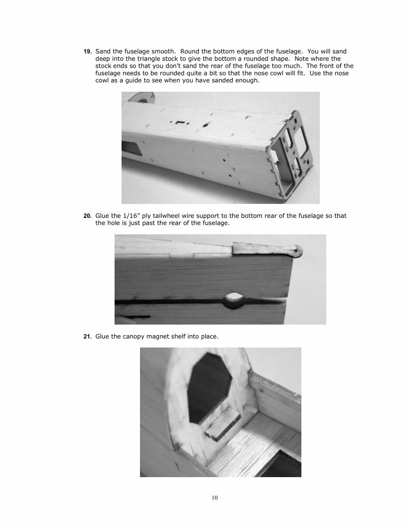
19. Sand the fuselage smooth. Round the bottom edges of the fuselage. You will sand deep into the triangle stock to give the bottom a rounded shape. Note where the stock ends so that you don�t sand the rear of the fuselage too much. The front of the fuselage needs to be rounded quite a bit so that the nose cowl will fit. Use the nose cowl as a guide to see when you have sanded enough.
20. Glue the 1/16� ply tailwheel wire support to the bottom rear of the fuselage so that the hole is just past the rear of the fuselage.
21. Glue the canopy magnet shelf into place.

11
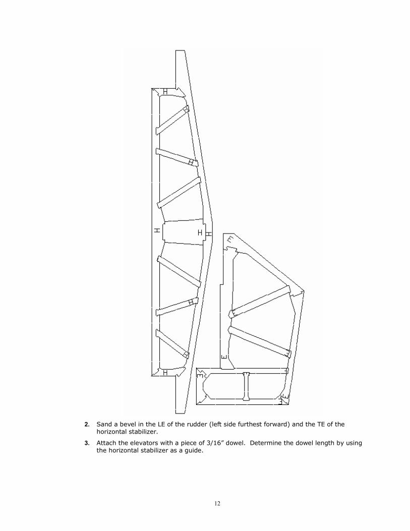
Assembling the Stabilizers, Rudder, and Elevator 1. Make the parts look like the images below. The parts are labeled V for vertical
stabilizer, H for horizontal stabilizer, R for rudder, and E for elevator. The images are not to scale.
12
2. Sand a bevel in the LE of the rudder (left side furthest forward) and the TE of the horizontal stabilizer.
3. Attach the elevators with a piece of 3/16� dowel. Determine the dowel length by using the horizontal stabilizer as a guide.

13
Shaping the Tail Wheel Wire and Attaching it to the Rudder You need to shape the tail wheel wire and attach it to the rudder before you attach the rudder to the fuselage.
! Shaping the tail wheel wire
Bend a 1/32� x 2.5� wire following these steps:
Needle nose pliers work pretty well to shape the wire.
1. Put a 90° bend into the wire 3/8� in from the end.
2. From that bend, go in 3/8� and create a slight 45° bend.
3. From that bend, you want to straighten out the wire so that it runs parallel to the
section of wire on the other side of the 45° bend.
4. The photo above is the view from the rear. The bend going up is where you attach the
wheel. The side view of the completed wire is something like this:
This end is pushed into the rudder
.5�
1� This is inserted into the fuselage 1/16ply guide.
.5�
Wheel goes This side goes here. into the rudder

14
5. Note that you do not attach the wheel until the rudder is installed to the fuselage. This happens after the rudder is covered.
6. Press the tailwheel wire into the front of the rudder ½� from the bottom. Wrap Tyvek (the white fiber paper) around the wire and secure with thin CA.
Assembling the Wheel Pants and Landing Gear 1. You will need to glue the wheel pants pieces together. Below is a photo of all the
pieces in the order that they are assembled. One side is assembled right to left, the other side is assembled left to right. The 1/16� ply is inserted into the second 1/16� balsa sheet.
2. The parts can be glued with thick CA or wood glue. Try to get them reasonably well aligned.

15
3. Sand the wheel pants to a nice rounded shape.
4. Paint the wheel pants with a few coats of primer, sanded between coats, then a final color coat.
5. Insert a 4-40 x 1� bolt into a wheel. Screw on one lock nut and tighten to the point just before the wheel binds. Slide the wheel into one of the wheel pants with the screw extending out the side of the wheel pants with the slot. Insert this arrangement onto the aluminum landing gear. Fasten with another lock nut.
Assembling the Canopy You are going to assemble and attach the canopy base, which once in place will be used to hold the plastic canopy in place.
1. Position the two 1/8 balsa front formers to the canopy base.
2. Make sure that all of the pieces are perpendicular, and then glue the joints.
3. Glue the 1/16� x 4.3� x .5� balsa strip to the notches in the two formers.

16
4. Draw a centerline down the balsa strip you just glued.
5. Align a 1/32 sheet with the centerline. Note that the 1/32� sheet is not square. One side is cut at an angle. Glue with thin CA to the balsa strip.
6. Dampen the 1/32 sheet so that it will bend around the formers and glue it to the formers.
7. Glue the other 1/32� sheet to the other side of the canopy base.
8. Trim the 1/32� sheet flush with the bottom of the ply base.
9. Place the canopy base in position on the fuselage. With a sheet of wax paper between the canopy base and the fuselage, position the rear canopy base 1/8� balsa former in position at the rear of the base. Match the angle of the fuselage former that it rests against.
10. With the wax paper protecting the fuselage from the glue, glue the rear former to the base.

17
11. Position the plastic canopy over the canopy base.
12. Using a fine point marker, mark the front, sides, and rear of the plastic canopy where it meets the canopy mount. Basically, trace an outline of the canopy mount onto the plastic canopy.
13. Cut out the plastic canopy, using the marks you created above. It is best to make one cut ¼� wide, then cut second time on the line.
14. Wash the canopy in dishwashing liquid. This removes the mold release and allows better adhesion for the glue.
If you plan on painting the canopy, you're going to have to do it before it's all glued in place. Once the canopy is washed, use a Scotch Brite pad to scuff the plastic so that the paint adheres better. You should use the paint recommended for R/C car bodies (polycarbonate / lexan). This is also the time for you to paint the canopy frame.
15. Cover or paint the canopy base. You can not easily do this once the canopy is in place.
16. Glue the canopy into place using 5 minute epoxy or canopy glue. Another option is to tape the canopy to the base.
Sanding and Covering The next step is to sand the pieces that need to be sanded and cover everything.
We aren�t going to go into how to cover the pieces themselves, you�re going to have to refer to your covering�s instructions for this information. Additionally, we aren�t going to cover our kit for instructional purposes, since the covering hides too much.
Sanding the Eva What we recommend:
• 200 grit sandpaper for sanding
What to Sand This is a fairly small chore for the Eva; apparently the air prefers sharp edges to rounded ones, so we aren�t going to round any of the pieces. Mind you, by sharp edges we don�t mean pokey bits, you ARE going to have to sand those, we just mean non- rounded bits.
• While sanding, try to go over the entire edge in a sweeping motion, avoiding any part of the assembly that is to remain non-beveled. This will make sure that your bevel angle is even across the entire way.
• Make sure that you sand lengthwise with the grain and not across it, as this will cause less strain on the wood and less chance of breaking the pieces.
• Using a tack cloth, carefully remove the balsa dust once you are done sanding.

18
Covering the Eva Determine what material you�ll use to cover, we recommend using Solite covering material since it is extremely lightweight and won�t crush the balsa when shrinking.
Do not shrink the covering until both sides of each part are covered. This reduces your chances of twisting the surfaces.
♦ Follow the instructions that come with the covering. Plan on going through a lot of xacto blades.
♦ Do not cover the bottom of the vertical stabilizer. This is where it will connect to the sheeting.
Installing the Tail Feathers For this step, you are going to install the horizontal stabilizer, elevator, the vertical stabilizer and the rudder to the fuselage using packing tape hinges. Also within this section we are going to install the elevator and rudder servos, and route the pushrods.
Once you�re done with this entire step, you will have a finished tail feather section!
Installing the Horizontal Stabilizer and Elevator First, you are going to install the horizontal stabilizer and elevator. You�re one step closer to completed tail feathers�
Removing the Covering from the Horizontal Stabilizer You need to remove some of the covering on the horizontal stabilizer so that you can securely attach it to the fuselage.
! Removing the covering
1. Position the horizontal stabilizer into the larger rear slot in the side of the fuselage. Make sure that it�s centered by measuring the distance from the outermost point of the horizontal stabilizer trailing edge to the rear of the fuselage on both sides; the numbers should match. Double check with a quick eyeballing, does it look right?
2. Mark a line on the horizontal stabilizer to show where it touches the fuselage on both the top and bottom.
3. GENTLY cut and remove the covering from between the marks. Be EXTREMELY careful that you are only cutting the covering and not the wood when you�re doing this, since scored wood is weak wood. Use a NEW exacto blade. DO NOT GLUE YET.
Attaching the Elevator and the Horizontal Stabilizer 1. Attach the elevator to the horizontal stabilizer with hinge tape. I use 2� packing tape
cut down to 1� width. The front of the bevel is on the top and the control horn is on the right.
2. Insert the horizontal stabilizer /elevator through the slot at the back of the fuselage, making sure that the control horn is on the right side when looking at the plane from the rear.

19
Installing the Vertical Stabilizer and Rudder Next, you are going to install the vertical stabilizer and rudder.
Attaching the Vertical Stabilizer
• Position the vertical stabilizer into the slot in the rear turtledeck, making sure that the rear of the stabilizer lines up with the rear of the fuselage and that it�s perpendicular to the elevator. Glue with thin CA.
! Attaching the hinges
Tape the rudder to the vertical stabilizer with packing tape or hinge tape. Make sure the rudder can move freely both directions.
Installing the Elevator and Rudder Servos
! Installing the servos
1. The tail feather servo holes are sized for HS55 size servos.
2. Flow some thin CA into where the servo screws go into the servo openings so as to strengthen the wood. Try not to clog the screw pilot holes, and make sure you allow the glue to dry completely.
3. Position the servos into the servo tray so that they are straight, and then screw them into place using the screws that came with your servos.
Attaching the Control Horns
! Attaching the control horns
Insert the control horns into their appropriate slots. The elevator horn should be on the right and facing up. The rudder horn should be on the left. After checking to make sure that they�re aligned properly, glue them into place with plenty of thin CA.
Finish installing the Servos You will need:
• 2 - .025� x 18� thin music wire for the pushrods (Wire)
• Heat shrink tubing (Bagged Parts)

20
! Installing the pushrods
1. Cut two pieces of .032� wire 1 1/8� long. Make a small L bend in one end of each wire. The L bend should be about 1/8� long. Lightly sand each wire to ensure a good glue joint later.
2. Insure that the servo is centered. Make a Z bend in one end of a .025 wire. Attach the Z bend to a servo horn. Run the wire through the pushrod tube and cut the other end ¼� past the control horn. Slide a ½� long piece of heat shrink tubing over the pushrod wire. Slide the L bend wire into the tubing. Slide the small end of the L bend into the control horn and flip the .025 pushrod wire over the horn, thus holding the pushrod in place.
3. Center the surface and shrink the tubing.
4. Once everything is adjusted, flow some thin CA into the heat shrink tubing to bond everything securely.
Correct Control Horn Hole Selection
Hole closer to the control surface = more throw
Hole further from the control surface = less throw
Correct Servo Horn Hole Selection Hole closer to the servo = less throw
Hole further from the servo = more throw
Installing the Motor We recommend a brushless motor rated for around 100 watts ( more if you�re crazy like us). The GWS EPS350C-C will also work as a low cost alternative but won�t have enough power for good 3D flying.
! Installing the Motor
1. Chose if you want a front firewall mount or a stick mount. Because the motor mount unbolts, you can change mounts later.
2. You will want to glue the mounts together with epoxy, rather than CA. Epoxy can handle the vibration of a slightly out of balance propeller better than CA can.
3. Assemble the motor mount as shown in the photos. Make sure the parts are seated properly to ensure the thrust angles are correct.

21
4. The rear firewall mount is for rear mount outrunner motors.
5. If you use the stick mount, retain the motor with the 2-56 wood screw.
Attaching the Receiver and Speed Controller We are not going to cover the receiver and speed controller (ESC) specific information, please refer to your manufacturer�s instructions for more information, if necessary.
! Attaching the Receiver
• The receiver is attached within the fuselage, behind the batteries. Use adhesive Velcro and attach it to the ply crutch near the rear.. Connect the servos and ESC to the receiver, following the guides on the receiver itself.
! Attaching the ESC
• The speed controller is attached within the fuselage, forward of the batteries. I just let my ESC hang loose. Connect the battery and the motor to the ESC, following the guides on the controller itself.
Finishing the Kit Well, you�re almost there�the end is in sight; just a few more steps and you can go flying, assuming the weather is cooperating.
Attaching the Tail Wheel
! Attaching the tail wheel
1. Slide the tail wheel over the tail wheel wire.
2. Bend the wire to retain the wheel.
Attaching the Battery No matter what battery pack you use, its attachment to the battery mount will be the same.
1. Assemble the battery tray as shown.

22
2. The stop on the right is 1/8� ply and is located between the two engraved lines.
3. Install the tray forward end first then slide it into the locked position.
4. Cut the rough side of the Velcro strip down to 5� in length, and attach it to the top of the battery tray so that it�s centered on the battery�s position.
5. Attach the soft side of the Velcro strip to the bottom of your battery pack.
6. After you attach the battery pack onto the mount, run the 6� double-sided Velcro strip underneath the battery mount, around the top of the battery pack, and then secure it to itself snugly. This acts as a seatbelt, holding the battery pack securely in place.
Typically, losing your battery in mid-flight is a bad thing�a very bad thing�
Attaching the Landing Gear The landing gear is pressed onto the T nuts and screwed in place. Use washers over the hex head screws and don�t over tighten the screws or you will crush the balsa fuselage bottom.
Attaching the Canopy 1. Glue one magnet to the bottom rear of the canopy base, centered on the base. Use
thick CA. You may want to lightly sand the magnet where you apply the glue to ensure a good bond.
2. Allow the second magnet to stick to the first magnet to assure the polarity is correct.
3. Apply a drop of thick CA to the end of the second magnet and press the canopy into position in the fuselage, allowing the second magnet to bond the magnet holder in the fuselage. Allow at least five minutes to ensure a proper bond.

23
Attaching the Nose Cowl 1. Trim the nose cowl flush with the rear flange.
2. Carefully open the three openings in the front of the cowl.
3. Attach the cowl to the fuselage with clear tape.
Attaching the Wing 4. Mark the middle of the carbon fiber spar. A sharpie works well for this. DO NOT
NICK THE SPAR.
5. Slide the spar into the fuselage then slide the wings on to the spar, ensuring that the rear wing alignment tabs slide into the slots in the fuselage sides. Check that the spar is still centered in the fuselage.
6. Retain the wing with a hex head screw and washer from inside of the fuselage to the T nut you inserted in the root spar.
Setting the Throws The amount of throws are determined by what wing you use. The wing manual will describe the required throws.
Setting the Center of Gravity The Center of Gravity (CG) is determined by the wing. See the wing manual.