extreme 2 reverse osmosis system - leader evaporator · leader evaporator co., inc. 49 jonergin...
TRANSCRIPT

Leader Evaporator Co., Inc.
49 Jonergin Drive
Swanton, VT 05488
Tel: 802-868-5444
www.leaderevaporator.com
EXTREME 2
Reverse Osmosis System
Leader Evaporator Springtech EXTREME 2 Reverse Osmosis System Manual YEAR: 2017 Page: 2
TABLEOFCONTENTS
INTRODUCTION .......................................................................................................................................................................... 4
THEORY OF OPERATION .............................................................................................................................................................. 4
Terms .............................................................................................................................................................................................. 4
Description of Membrane ............................................................................................................................................................... 5
EQUIPMENT DESCRIPTION .......................................................................................................................................................... 6
FRONT VIEW ........................................................................................................................................................................................... 6
REAR VIEW ............................................................................................................................................................................................. 6
FEED PUMP ............................................................................................................................................................................................ 7
PRESSURE PUMP ..................................................................................................................................................................................... 7
RECIRCULATION PUMPS ............................................................................................................................................................................ 7
PREFILTER ASSEMBLY AND WASH TANK ....................................................................................................................................................... 7
CONTROL PANEL ..................................................................................................................................................................................... 8
FLOW METERS ........................................................................................................................................................................................ 8
PRESSURE GAUGES .................................................................................................................................................................................. 8
SAMPLING PORTS .................................................................................................................................................................................... 9
V1 AND V2 VALVES ................................................................................................................................................................................. 9
FLOW CONTROL VALVES ........................................................................................................................................................................... 9
INCLUDED EQUIPMENT ........................................................................................................................................................................... 10
OPTIONAL SETUP EQUIPMENT, PARTS AND SUPPLIES .................................................................................................................................... 10
SETUP ....................................................................................................................................................................................... 11
AREA REQUIRED .................................................................................................................................................................................... 11
POWER REQUIREMENTS .......................................................................................................................................................................... 11
Electrical Schematic ...................................................................................................................................................................... 12
GENERAL CONNECTION LAYOUT ............................................................................................................................................................... 12
SIMPLE 3 TANK R/O DIAGRAM ..................................................................................................................................................... 12
STRAINER CONNECTIONS ......................................................................................................................................................................... 13
V6 CONNECTION ................................................................................................................................................................................... 13
WD CONNECTION ................................................................................................................................................................................. 14
VESSEL AND PUMP DRAINS ...................................................................................................................................................................... 14
V3, V4 AND V19 CONNECTIONS .............................................................................................................................................................. 15
V19 – Connection To Drain ........................................................................................................................................................... 16
V3 – Connection To Permeate Storage ......................................................................................................................................... 16
V4 – Connection To Concentrate Storage ..................................................................................................................................... 16
OPERATION .............................................................................................................................................................................. 17
STARTUP OF SYSTEM WITH LITTLE OR NO FLUID ........................................................................................................................................... 17
INITIAL SYSTEM CLEANING ....................................................................................................................................................................... 18
DATA LOGGING ..................................................................................................................................................................................... 18
CYCLES AND TIMING ............................................................................................................................................................................... 19
PERMEABILITY TEST ................................................................................................................................................................................ 19
FLOW VALVE INFORMATION .................................................................................................................................................................... 22
ADJUSTING V1 AND V2 FOR OPERATIONS .................................................................................................................................................. 22
SAMPLE PORT USE ................................................................................................................................................................................. 23
CONCENTRATE CYCLE ............................................................................................................................................................................. 23
DESUGAR CYCLE .................................................................................................................................................................................... 25
RINSE CYCLE ......................................................................................................................................................................................... 27
Leader Evaporator Springtech EXTREME 2 Reverse Osmosis System Manual YEAR: 2017 Page: 3
WASH CYCLE ........................................................................................................................................................................................ 30
Hot Water Wash ........................................................................................................................................................................... 30
Alkaline Soap Wash ...................................................................................................................................................................... 30
Acid Soak ...................................................................................................................................................................................... 30
MAINTENANCE ......................................................................................................................................................................... 33
PRE FILTERS .......................................................................................................................................................................................... 33
MEMBRANE REMOVAL AND INSTALLATION ................................................................................................................................................. 34
Removal ........................................................................................................................................................................................ 34
Installation ................................................................................................................................................................................... 35
DAILY .................................................................................................................................................................................................. 37
PERIODIC ............................................................................................................................................................................................. 37
END OF SEASON SHUTDOWN AND STORAGE ............................................................................................................................................... 38
BEGINNING OF SEASON STARTUP .............................................................................................................................................................. 39
TROUBLESHOOTING CHART ...................................................................................................................................................... 41
ATTACHMENT #1 – ELECTRICAL SCHEMATICS ............................................................................................................................ 42
ATTACHMENT #2 – OPERATION DATA LOGSHEET ...................................................................................................................... 43
ATTACHMENT #3 – MEMBRANE PERMEABILITY TEST SHEET ...................................................................................................... 44
ATTACHMENT #4 – WARRANTY INFORMATION ......................................................................................................................... 45
Leader Evaporator Springtech EXTREME 2 Reverse Osmosis System Manual YEAR: 2017 Page: 4
INTRODUCTIONA Leader Evaporator Springtech EXTREME Reverse Osmosis system is designed to significantly improve the producer’s
productivity by generating high sugar percentage sap. Through use of high pressure, the system removes water from
the sap resulting in a more concentrated sugar solution entering the evaporator. This in turn shortens the boil time
required resulting in fuel and time savings.
Some of the features of the Springtech EXTREME 2 are:
Easy accessibility to pumps and membranes
Stainless steel frame, membrane housings, pumps and pump housings
Fast wash cycle
With reasonable sap – the ability to generate high brix concentrate with a single pass
Flow meters for the permeate of each membrane and one for the system concentrate
THEORYOFOPERATIONIn reverse osmosis, through the use of special semi‐permeable membranes and high pressure, water is forced, in a
pure form, through the membrane while the concentrated solution remains outside the membrane and is
concentrated. For the sugar maker this means water (permeate) is removed from the sap and a sap with a higher
sugar level (concentrate) is produced for the evaporation process.
Terms
Semi‐permeable Membrane – Unit consisting of multi layers of spacers and membranes
Pre‐Filter Unit – Designed to remove suspended solids from the sap incoming to the reverse osmosis
system
Feed Pump – The initial pump designed to supply the reverse osmosis unit with sap and maintain pressure
in the system
Pressure Pump – The pump designed to provide the pressure needed to force the sap through the reverse
osmosis membrane
Pressure Vessel – The containment unit for the semi‐permeable membrane
Permeate – Purified water removed from the maple sap during the concentrate cycle
Concentrate – the maple sap having a higher percentage of sugar because water (permeate) has
been removed
Permeate Holding Tank – A tank designed to hold a minimum twice the hourly output of the system
Concentrate Cycle – Process during which water is removed from maple sap resulting in
Concentrate and Permeate
De‐Sugaring Cycle ‐ Process to reclaim sugars from the membrane during which Permeate is run
through the reverse osmosis unit using Concentrate cycle valve settings
Rinse Cycle – Cleaning process of passing stored Permeate through the Reverse Osmosis system and
out to drain
Chemical Wash Cycle – Process of chemical washing the membranes by recirculating a solution
through the reverse osmosis system. Dependent on requirement, chemical maybe be
alkali or acid.
Permeability Test – Test to determine the performance of the membranes against a benchmark
Sap Recirculation Loop – Process of recirculating output from the concentrate cycle to the raw sap
tank, increasing the concentration of the sap in the tank
Leader Evaporator Springtech EXTREME 2 Reverse Osmosis System Manual YEAR: 2017 Page: 5
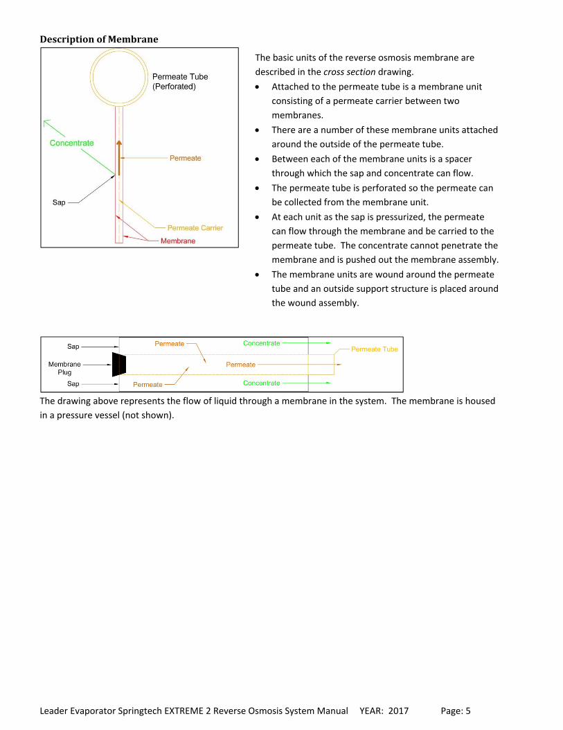
DescriptionofMembrane
The drawing above represents the flow of liquid through a membrane in the system. The membrane is housed
in a pressure vessel (not shown).
The basic units of the reverse osmosis membrane are
described in the cross section drawing.
Attached to the permeate tube is a membrane unit
consisting of a permeate carrier between two
membranes.
There are a number of these membrane units attached
around the outside of the permeate tube.
Between each of the membrane units is a spacer
through which the sap and concentrate can flow.
The permeate tube is perforated so the permeate can
be collected from the membrane unit.
At each unit as the sap is pressurized, the permeate
can flow through the membrane and be carried to the
permeate tube. The concentrate cannot penetrate the
membrane and is pushed out the membrane assembly.
The membrane units are wound around the permeate
tube and an outside support structure is placed around
the wound assembly.
Leader Evaporator Springtech EXTREME 2 Reverse Osmosis System Manual YEAR: 2017 Page: 6
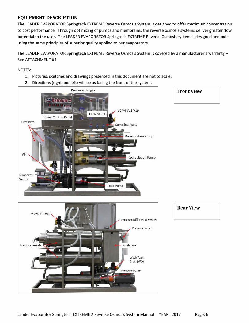
EQUIPMENTDESCRIPTIONThe LEADER EVAPORATOR Springtech EXTREME Reverse Osmosis System is designed to offer maximum concentration
to cost performance. Through optimizing of pumps and membranes the reverse osmosis systems deliver greater flow
potential to the user. The LEADER EVAPORATOR Springtech EXTREME Reverse Osmosis system is designed and built
using the same principles of superior quality applied to our evaporators.
The LEADER EVAPORATOR Springtech EXTREME Reverse Osmosis System is covered by a manufacturer’s warranty –
See ATTACHMENT #4.
NOTES:
1. Pictures, sketches and drawings presented in this document are not to scale.
2. Directions (right and left) will be as facing the front of the system.
FrontView
RearView
Leader Evaporator Springtech EXTREME 2 Reverse Osmosis System Manual YEAR: 2017 Page: 7
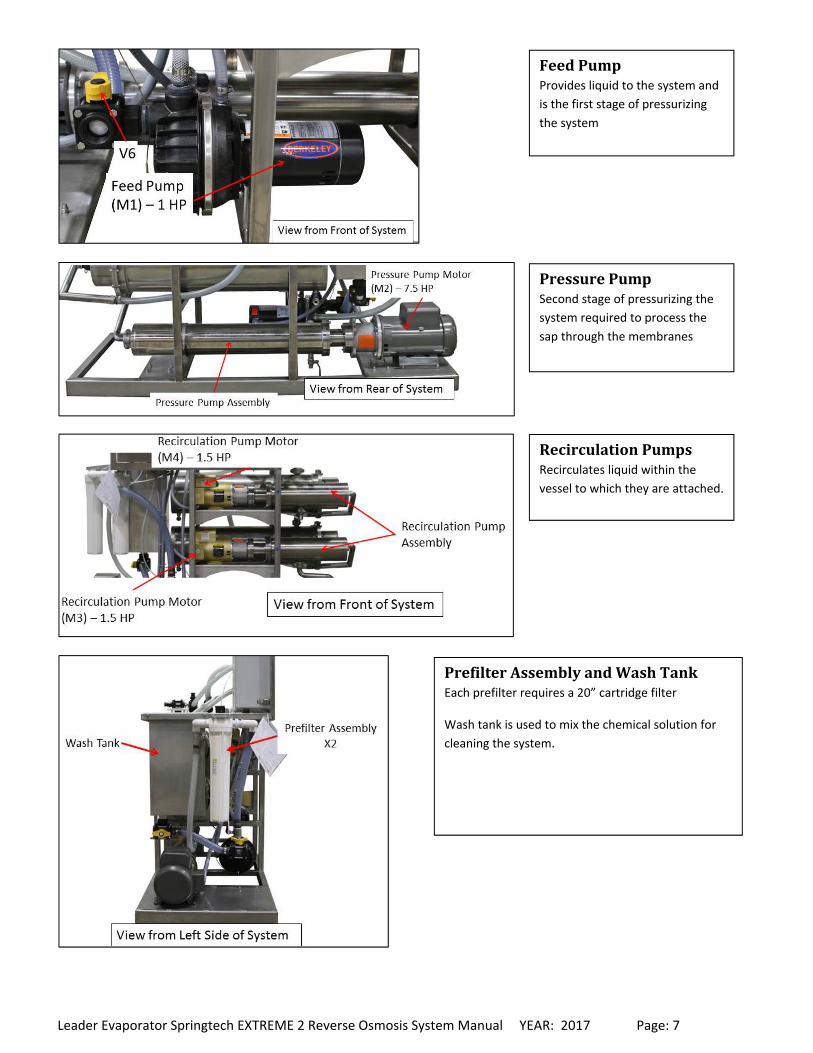
FeedPumpProvides liquid to the system and
is the first stage of pressurizing
the system
PressurePumpSecond stage of pressurizing the
system required to process the
sap through the membranes
RecirculationPumpsRecirculates liquid within the
vessel to which they are attached.
PrefilterAssemblyandWashTankEach prefilter requires a 20” cartridge filter
Wash tank is used to mix the chemical solution for
cleaning the system.
Leader Evaporator Springtech EXTREME 2 Reverse Osmosis System Manual YEAR: 2017 Page: 8
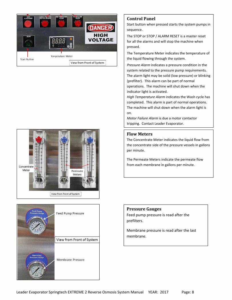
ControlPanelStart button when pressed starts the system pumps in
sequence.
The STOP or STOP / ALARM RESET is a master reset
for all the alarms and will stop the machine when
pressed.
The Temperature Meter indicates the temperature of
the liquid flowing through the system.
Pressure Alarm indicates a pressure condition in the
system related to the pressure pump requirements.
The alarm light may be solid (low pressure) or blinking
(prefilter). This alarm can be part of normal
operations. The machine will shut down when the
indicator light is activated.
High Temperature Alarm indicates the Wash cycle has
completed. This alarm is part of normal operations.
The machine will shut down when the alarm light is
on.
Motor Failure Alarm is due a motor contactor
tripping. Contact Leader Evaporator.
FlowMetersThe Concentrate Meter indicates the liquid flow from
the concentrate side of the pressure vessels in gallons
per minute.
The Permeate Meters indicate the permeate flow
from each membrane in gallons per minute.
PressureGaugesFeed pump pressure is read after the
prefilters.
Membrane pressure is read after the last
membrane.
Leader Evaporator Springtech EXTREME 2 Reverse Osmosis System Manual YEAR: 2017 Page: 9
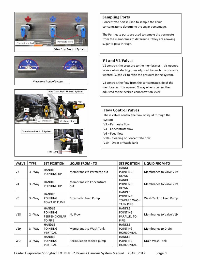
VALVE TYPE SET POSITION LIQUID FROM ‐ TO SET POSITION LIQUID FROM‐TO
V3 3 ‐ Way HANDLE POINTING UP
Membranes to Permeate out HANDLE POINTING DOWN
Membranes to Valve V19
V4 3 ‐ Way HANDLE POINTING UP
Membranes to Concentrate out
HANDLE POINTING DOWN
Membranes to Valve V19
V6 3 ‐ Way HANDLE POINTING TOWARD PUMP
External to Feed Pump
HANDLE POINTING TOWARD WASH TANK PIPE
Wash Tank to Feed Pump
V18 2 ‐ Way
HANDLE POINTING PERPENDICULAR TO PIPE
No Flow
HANDLE POINTING PARALLEL TO PIPE
Membranes to Valve V19
V19 3 ‐ Way HANDLE POINTING VERTICAL
Membranes to Wash Tank HANDLE POINTING HORIZONTAL
Membranes to Drain
WD 3 ‐ Way HANDLE POINTING VERTICAL
Recirculation to feed pump HANDLE POINTING HORIZONTAL
Drain Wash Tank
SamplingPortsConcentrate port is used to sample the liquid
concentrate to determine the sugar percentage.
The Permeate ports are used to sample the permeate
from the membranes to determine if they are allowing
sugar to pass through.
V1andV2ValvesV1 controls the pressure to the membranes. It is opened
½ way when starting then adjusted to reach the pressure
wanted. Close V1 to raise the pressure in the system.
V2 controls the flow from the concentrate side of the
membranes. It is opened ½ way when starting then
adjusted to the desired concentration level.
FlowControlValvesThese valves control the flow of liquid through the
system
V3 – Permeate flow
V4 – Concentrate flow
V6 – Feed flow
V18 – Cleaning or Concentrate flow
V19 – Drain or Wash Tank
Leader Evaporator Springtech EXTREME 2 Reverse Osmosis System Manual YEAR: 2017 Page: 10
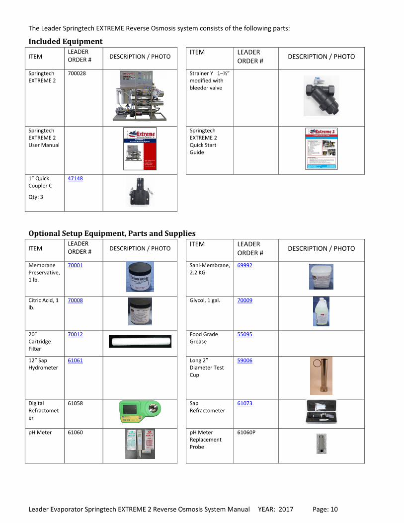
The Leader Springtech EXTREME Reverse Osmosis system consists of the following parts:
IncludedEquipment
ITEM LEADER ORDER # DESCRIPTION / PHOTO
ITEM LEADER ORDER #
DESCRIPTION / PHOTO
Springtech EXTREME 2
700028
Strainer Y 1–½” modified with bleeder valve
Springtech EXTREME 2 User Manual
Springtech EXTREME 2 Quick Start Guide
1” Quick Coupler C
Qty: 3
47148
OptionalSetupEquipment,PartsandSupplies
ITEM LEADER ORDER # DESCRIPTION / PHOTO
ITEM LEADER ORDER #
DESCRIPTION / PHOTO
Membrane Preservative, 1 lb.
70001
Sani‐Membrane, 2.2 KG
69992
Citric Acid, 1 lb.
70008
Glycol, 1 gal. 70009
20” Cartridge Filter
70012
Food Grade Grease
55095
12” Sap Hydrometer
61061
Long 2” Diameter Test Cup
59006
Digital Refractometer
61058
Sap Refractometer
61073
pH Meter 61060
pH Meter Replacement Probe
61060P
Leader Evaporator Springtech EXTREME 2 Reverse Osmosis System Manual YEAR: 2017 Page: 11
SETUPNOTES:
All materials used should be approved for potable water. No copper should be used.
When installing plumbing for the system, factor in the system may need to be moved for such items as
maintenance. It is recommended the connections be made with fittings such as quick disconnects.
All feed piping to the Springtech system must be at least as large as the feed on the system itself – 2” is
recommended
All installations must meet applicable governmental regulations.
AreaRequiredThe space to be used should be capable of preventing the RO system from freezing. Additionally it will need to have
adequate ventilation during operations to prevent overheating.
The dimensions of the unit are
Width – 34”
Length – 75”
Height – 71”
A minimum of two feet around the system is recommended. You must also be able to obtain an additional 4 feet in
length in order to remove membranes and pump assemblies.
The room should have adequate drainage. The walls, ceiling and floor should be easy to clean.
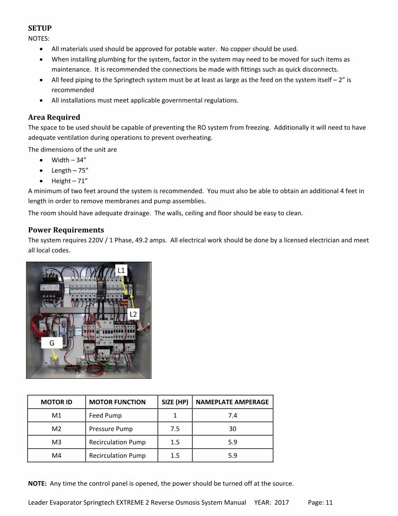
PowerRequirementsThe system requires 220V / 1 Phase, 49.2 amps. All electrical work should be done by a licensed electrician and meet
all local codes.
MOTOR ID MOTOR FUNCTION SIZE (HP) NAMEPLATE AMPERAGE
M1 Feed Pump 1 7.4
M2 Pressure Pump 7.5 30
M3 Recirculation Pump 1.5 5.9
M4 Recirculation Pump 1.5 5.9
NOTE: Any time the control panel is opened, the power should be turned off at the source.

Leader Evaporator Springtech EXTREME 2 Reverse Osmosis System Manual YEAR: 2017 Page: 12
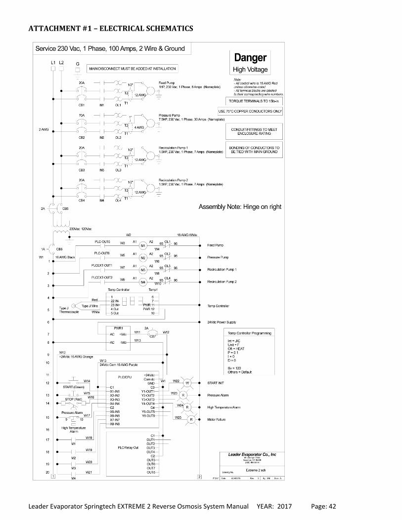
ElectricalSchematicThe schematic for the system is located in – ATTACHMENT #1
GeneralConnectionLayoutThe following illustrates a generalized layout for connections with the Springtech EXTREME RO System. The first
drawing shows tank connections to the system. The second drawing shows an arrangement of valves to connect the
incoming liquid to the system. Dependent on the location, other arrangements are likely. It is beyond the scope of
this document to recommend the best layout for all situations. It is recommended you contact your LEADER
EVAPORATOR sales person or your local Distributor / Dealer for assistance in deciding the correct tanks and layout for
your needs.
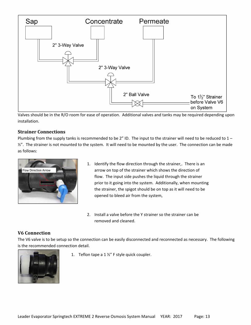
SIMPLE3TANKR/ODIAGRAM
Liquid Source Selector
Leader Evaporator Springtech EXTREME 2 Reverse Osmosis System Manual YEAR: 2017 Page: 13
Valves should be in the R/O room for ease of operation. Additional valves and tanks may be required depending upon
installation.
StrainerConnectionsPlumbing from the supply tanks is recommended to be 2” ID. The input to the strainer will need to be reduced to 1 –
½”. The strainer is not mounted to the system. It will need to be mounted by the user. The connection can be made
as follows:
V6ConnectionThe V6 valve is to be setup so the connection can be easily disconnected and reconnected as necessary. The following
is the recommended connection detail.
1. Teflon tape a 1 ½” F style quick coupler.
1. Identify the flow direction through the strainer,. There is an
arrow on top of the strainer which shows the direction of
flow. The input side pushes the liquid through the strainer
prior to it going into the system. Additionally, when mounting
the strainer, the spigot should be on top as it will need to be
opened to bleed air from the system,
2. Install a valve before the Y strainer so the strainer can be
removed and cleaned.
Leader Evaporator Springtech EXTREME 2 Reverse Osmosis System Manual YEAR: 2017 Page: 14
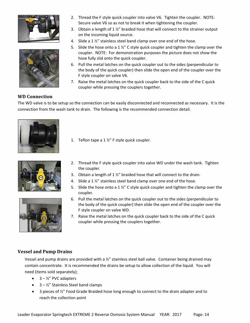
WDConnectionThe WD valve is to be setup so the connection can be easily disconnected and reconnected as necessary. It is the
connection from the wash tank to drain. The following is the recommended connection detail.
VesselandPumpDrains
Vessel and pump drains are provided with a ½” stainless steel ball valve. Container being drained may
contain concentrate. It is recommended the drains be setup to allow collection of the liquid. You will
need (items sold separately);
3 – ½” PVC adapters
3 – ½” Stainless Steel band clamps
3 pieces of ½” Food Grade Braided hose long enough to connect to the drain adapter and to
reach the collection point
2. Thread the F style quick coupler into valve V6. Tighten the coupler. NOTE: Secure valve V6 so as not to break it when tightening the coupler.
3. Obtain a length of 1 ½” braided hose that will connect to the strainer output on the incoming liquid source.
4. Slide a 1 ½” stainless steel band clamp over one end of the hose.
5. Slide the hose onto a 1 ½” C style quick coupler and tighten the clamp over the coupler. NOTE: For demonstration purposes the picture does not show the hose fully slid onto the quick coupler.
6. Pull the metal latches on the quick coupler out to the sides (perpendicular to the body of the quick coupler) then slide the open end of the coupler over the F style coupler on valve V6.
7. Raise the metal latches on the quick coupler back to the side of the C quick coupler while pressing the couplers together.
1. Teflon tape a 1 ½” F style quick coupler.
2. Thread the F style quick coupler into valve WD under the wash tank. Tighten the coupler.
3. Obtain a length of 1 ½” braided hose that will connect to the drain.
4. Slide a 1 ½” stainless steel band clamp over one end of the hose.
5. Slide the hose onto a 1 ½” C style quick coupler and tighten the clamp over the coupler.
6. Pull the metal latches on the quick coupler out to the sides (perpendicular to the body of the quick coupler) then slide the open end of the coupler over the F style coupler on valve WD.
7. Raise the metal latches on the quick coupler back to the side of the C quick coupler while pressing the couplers together.
Leader Evaporator Springtech EXTREME 2 Reverse Osmosis System Manual YEAR: 2017 Page: 15
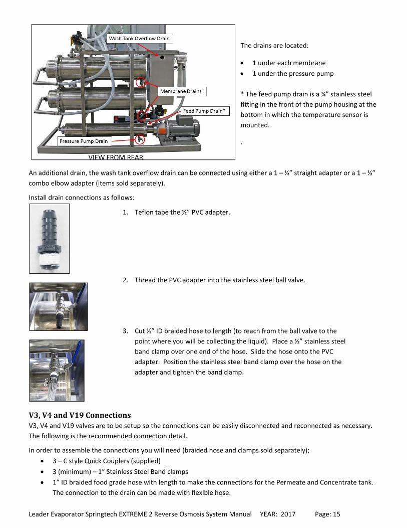
The drains are located:
1 under each membrane
1 under the pressure pump
* The feed pump drain is a ¼” stainless steel
fitting in the front of the pump housing at the
bottom in which the temperature sensor is
mounted.
.
An additional drain, the wash tank overflow drain can be connected using either a 1 – ½” straight adapter or a 1 – ½”
combo elbow adapter (items sold separately).
Install drain connections as follows:
V3,V4andV19ConnectionsV3, V4 and V19 valves are to be setup so the connections can be easily disconnected and reconnected as necessary.
The following is the recommended connection detail.
In order to assemble the connections you will need (braided hose and clamps sold separately);
3 – C style Quick Couplers (supplied)
3 (minimum) – 1” Stainless Steel Band clamps
1” ID braided food grade hose with length to make the connections for the Permeate and Concentrate tank.
The connection to the drain can be made with flexible hose.
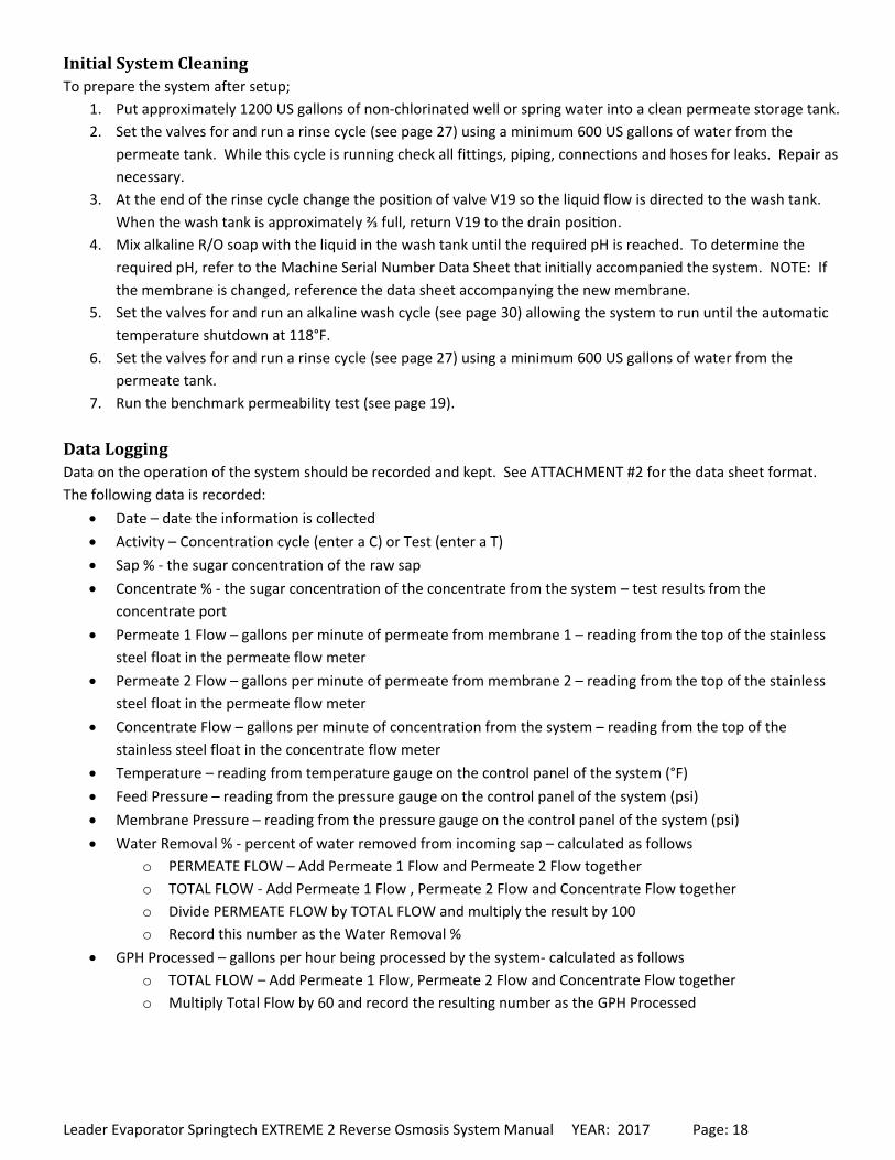
1. Teflon tape the ½” PVC adapter.
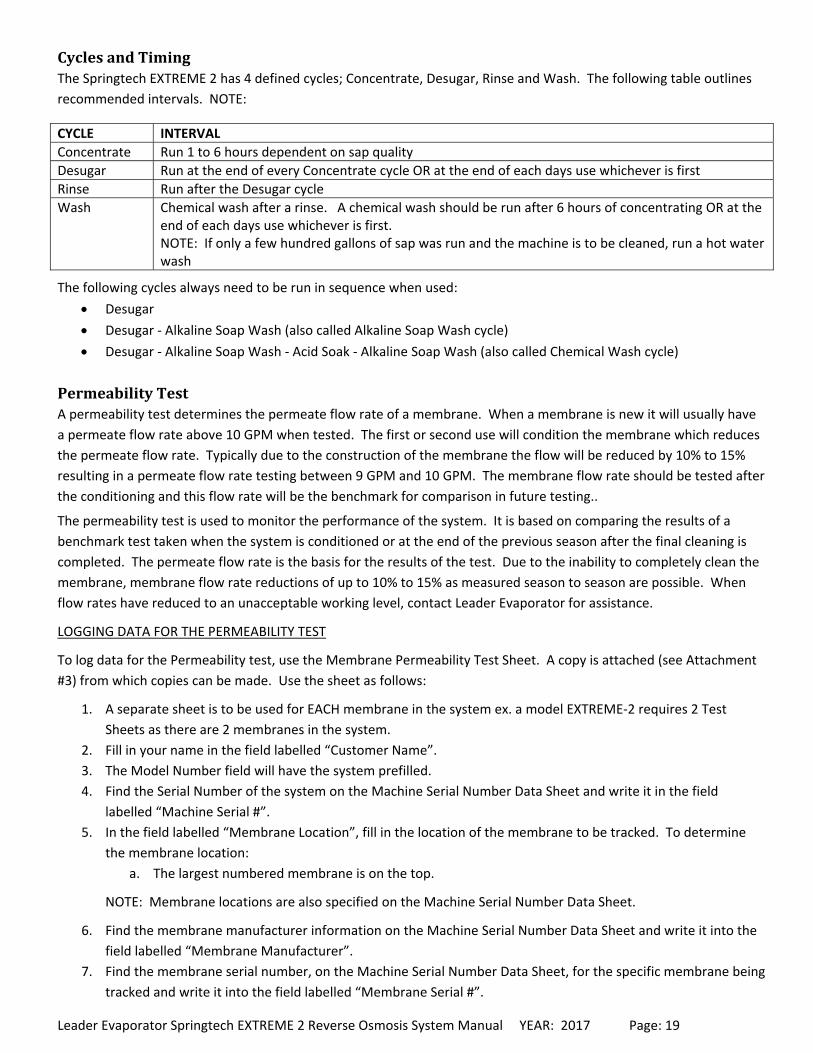
2. Thread the PVC adapter into the stainless steel ball valve.
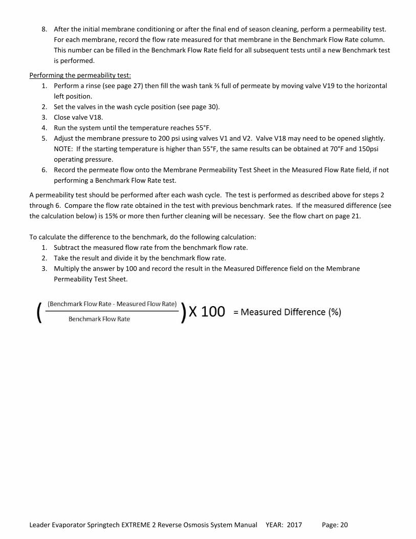
3. Cut ½” ID braided hose to length (to reach from the ball valve to the
point where you will be collecting the liquid). Place a ½” stainless steel
band clamp over one end of the hose. Slide the hose onto the PVC
adapter. Position the stainless steel band clamp over the hose on the
adapter and tighten the band clamp.

Leader Evaporator Springtech EXTREME 2 Reverse Osmosis System Manual YEAR: 2017 Page: 16
V19–ConnectionToDrain
V3–ConnectionToPermeateStorage
V4–ConnectionToConcentrateStorage
1. Cut 1” ID flexible hose to reach from the valve V19 to the drain
connection.
2. Place at least one 1” stainless steel band clamp over one end of the hose.
Slide the hose onto the 1” C style quick coupler.
3. Position the stainless steel band clamp(s) over the hose on the coupler
and tighten the band clamp(s).
4. Secure the other end of the hose to the drain connection.
5. Connect the quick couplers by opening the latches on the C style coupler
(position the metal latch arms out perpendicular to the body of the
coupler) then sliding the C coupler onto the F coupler. Pull the metal
latch arms back down to the sides of the C coupler.
1. Cut 1” ID braided hose to length – from valve V3 to the fill connection
for the permeate tank.
2. Place at least one 1” stainless steel band clamp over one end of the
hose.
3. Slide the hose onto a 1” C style quick coupler.
4. Position the stainless steel band clamp(s) over the hose on the adapter
and tighten the band clamps.
5. Secure the other end of the hoses to the tank fill connection.
6. Connect the quick couplers by opening the latch on the C style coupler
(position the metal latch arms out perpendicular to the body of the
coupler) then sliding the C coupler onto the F coupler. Pull the metal
latch arms back up to the sides of the C coupler.
1. Cut 1” ID braided hose to length – from valve V4 to the fill connection
for the concentrate tank.
2. Place at least one 1” stainless steel band clamp over one end of the
hose.
3. Slide the hose onto a 1” C style quick coupler.
4. Position the stainless steel band clamp(s) over the hose on the adapter
and tighten the band clamp(s).
5. Secure the other end of the hose to the tank fill connection.
6. Connect the quick couplers by opening the latch on the C style coupler
(position the metal latch arms out perpendicular to the body of the
coupler) then sliding the C coupler onto the F coupler. Pull the metal
latch arms back up to the sides of the C coupler.

Leader Evaporator Springtech EXTREME 2 Reverse Osmosis System Manual YEAR: 2017 Page: 17
OPERATION
When starting the Reverse Osmosis unit there is a sequence in which the pumps will activate. Pressing the START
button will first activate the feed pump. In normal operations within 30 seconds the pressure pump will start followed
by one recirculation pump and finishing with the second recirculation pump.
During any cycle if permeate is not available, use non chlorinated well or spring water.
StartupofSystemwithLittleorNoFluid1. Set the system valve for a rinse cycle (see page 27).
2. Turn off the power to the system at the source.
3. Open the control box by unfastening the latches/buckles on the left side then opening the door carefully to the
right.
4. Turn off the pressure and recirculation pump breakers:
BREAKER ID CIRCUIT START POSITION
CB1 Feed Pump ON
CB2 Pressure Pump OFF
CB3 1.5 HP Recirculation Pump OFF
CB4 1.5HP Recirculation Pump OFF
5. Close the control box cover and refasten the latches/buckles.
6. Turn on the power to the system at the source.
7. Ensure your source valves (water or permeate) are open to feed the system.
8. Press the START button to start the feed pump.
9. Run the feed pump until most of the bubbles are gone from the flow meters located on the front of the
system. This will take 3 to 4 minutes. Not all the bubbles can be removed.
10. Press the STOP button to stop the feed pump.
11. Turn off the power to the system at the source.
12. Open the control box by unfastening the latches/buckles on the left side then opening the door carefully to the
right.
13. Position breakers CB1, CB2, CB3 and CB4 to the ON position.
14. Close the control box cover and refasten the latches.
15. Turn on the power to the system at the source.
16. Proceed to the instructions for the Initial System Cleaning.
Leader Evaporator Springtech EXTREME 2 Reverse Osmosis System Manual YEAR: 2017 Page: 18
InitialSystemCleaningTo prepare the system after setup;
1. Put approximately 1200 US gallons of non‐chlorinated well or spring water into a clean permeate storage tank.
2. Set the valves for and run a rinse cycle (see page 27) using a minimum 600 US gallons of water from the
permeate tank. While this cycle is running check all fittings, piping, connections and hoses for leaks. Repair as
necessary.
3. At the end of the rinse cycle change the position of valve V19 so the liquid flow is directed to the wash tank.
When the wash tank is approximately ⅔ full, return V19 to the drain posi on.
4. Mix alkaline R/O soap with the liquid in the wash tank until the required pH is reached. To determine the
required pH, refer to the Machine Serial Number Data Sheet that initially accompanied the system. NOTE: If
the membrane is changed, reference the data sheet accompanying the new membrane.
5. Set the valves for and run an alkaline wash cycle (see page 30) allowing the system to run until the automatic
temperature shutdown at 118°F.
6. Set the valves for and run a rinse cycle (see page 27) using a minimum 600 US gallons of water from the
permeate tank.
7. Run the benchmark permeability test (see page 19).
DataLoggingData on the operation of the system should be recorded and kept. See ATTACHMENT #2 for the data sheet format.
The following data is recorded:
Date – date the information is collected
Activity – Concentration cycle (enter a C) or Test (enter a T)
Sap % ‐ the sugar concentration of the raw sap
Concentrate % ‐ the sugar concentration of the concentrate from the system – test results from the
concentrate port
Permeate 1 Flow – gallons per minute of permeate from membrane 1 – reading from the top of the stainless
steel float in the permeate flow meter
Permeate 2 Flow – gallons per minute of permeate from membrane 2 – reading from the top of the stainless
steel float in the permeate flow meter
Concentrate Flow – gallons per minute of concentration from the system – reading from the top of the
stainless steel float in the concentrate flow meter
Temperature – reading from temperature gauge on the control panel of the system (°F)
Feed Pressure – reading from the pressure gauge on the control panel of the system (psi)
Membrane Pressure – reading from the pressure gauge on the control panel of the system (psi)
Water Removal % ‐ percent of water removed from incoming sap – calculated as follows
o PERMEATE FLOW – Add Permeate 1 Flow and Permeate 2 Flow together
o TOTAL FLOW ‐ Add Permeate 1 Flow , Permeate 2 Flow and Concentrate Flow together
o Divide PERMEATE FLOW by TOTAL FLOW and multiply the result by 100
o Record this number as the Water Removal %
GPH Processed – gallons per hour being processed by the system‐ calculated as follows
o TOTAL FLOW – Add Permeate 1 Flow, Permeate 2 Flow and Concentrate Flow together
o Multiply Total Flow by 60 and record the resulting number as the GPH Processed
Leader Evaporator Springtech EXTREME 2 Reverse Osmosis System Manual YEAR: 2017 Page: 19
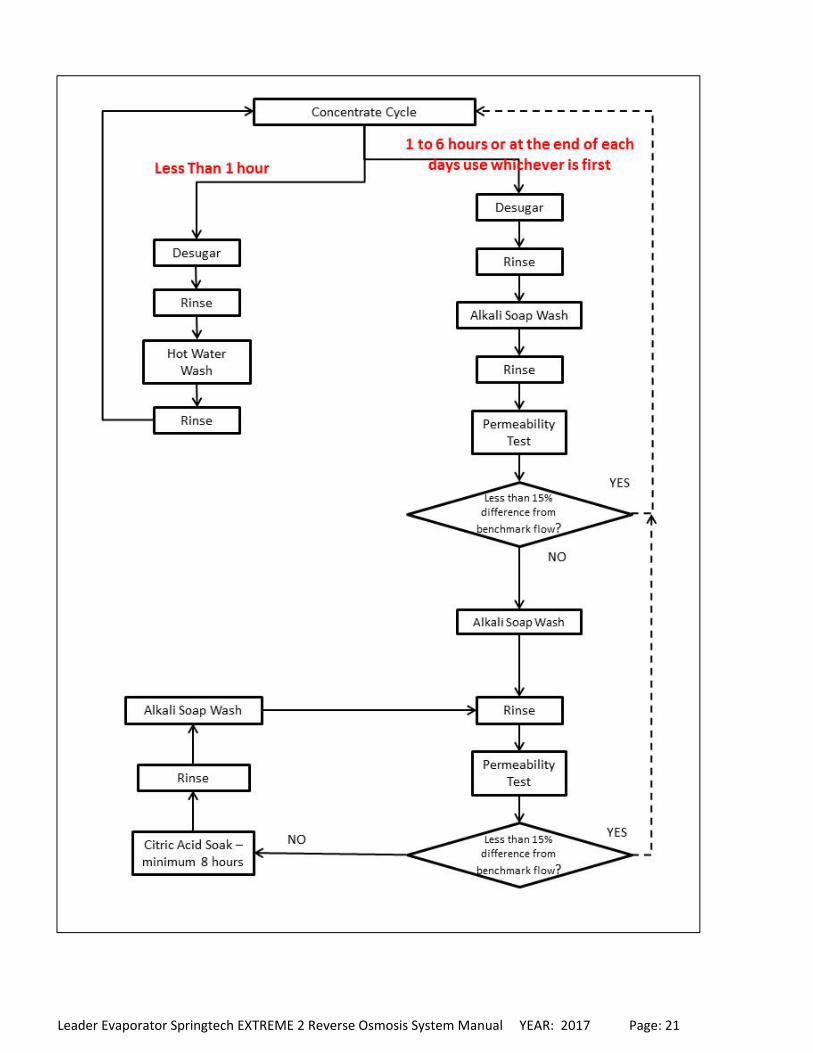
CyclesandTimingThe Springtech EXTREME 2 has 4 defined cycles; Concentrate, Desugar, Rinse and Wash. The following table outlines
recommended intervals. NOTE:
CYCLE INTERVAL
Concentrate Run 1 to 6 hours dependent on sap quality
Desugar Run at the end of every Concentrate cycle OR at the end of each days use whichever is first
Rinse Run after the Desugar cycle
Wash Chemical wash after a rinse. A chemical wash should be run after 6 hours of concentrating OR at the end of each days use whichever is first. NOTE: If only a few hundred gallons of sap was run and the machine is to be cleaned, run a hot water wash
The following cycles always need to be run in sequence when used:
Desugar
Desugar ‐ Alkaline Soap Wash (also called Alkaline Soap Wash cycle)
Desugar ‐ Alkaline Soap Wash ‐ Acid Soak ‐ Alkaline Soap Wash (also called Chemical Wash cycle)
PermeabilityTestA permeability test determines the permeate flow rate of a membrane. When a membrane is new it will usually have
a permeate flow rate above 10 GPM when tested. The first or second use will condition the membrane which reduces
the permeate flow rate. Typically due to the construction of the membrane the flow will be reduced by 10% to 15%
resulting in a permeate flow rate testing between 9 GPM and 10 GPM. The membrane flow rate should be tested after
the conditioning and this flow rate will be the benchmark for comparison in future testing..
The permeability test is used to monitor the performance of the system. It is based on comparing the results of a
benchmark test taken when the system is conditioned or at the end of the previous season after the final cleaning is
completed. The permeate flow rate is the basis for the results of the test. Due to the inability to completely clean the
membrane, membrane flow rate reductions of up to 10% to 15% as measured season to season are possible. When
flow rates have reduced to an unacceptable working level, contact Leader Evaporator for assistance.
LOGGING DATA FOR THE PERMEABILITY TEST
To log data for the Permeability test, use the Membrane Permeability Test Sheet. A copy is attached (see Attachment
#3) from which copies can be made. Use the sheet as follows:
1. A separate sheet is to be used for EACH membrane in the system ex. a model EXTREME‐2 requires 2 Test
Sheets as there are 2 membranes in the system.
2. Fill in your name in the field labelled “Customer Name”.
3. The Model Number field will have the system prefilled.
4. Find the Serial Number of the system on the Machine Serial Number Data Sheet and write it in the field
labelled “Machine Serial #”.
5. In the field labelled “Membrane Location”, fill in the location of the membrane to be tracked. To determine
the membrane location:
a. The largest numbered membrane is on the top.
NOTE: Membrane locations are also specified on the Machine Serial Number Data Sheet.
6. Find the membrane manufacturer information on the Machine Serial Number Data Sheet and write it into the
field labelled “Membrane Manufacturer”.
7. Find the membrane serial number, on the Machine Serial Number Data Sheet, for the specific membrane being
tracked and write it into the field labelled “Membrane Serial #”.
Leader Evaporator Springtech EXTREME 2 Reverse Osmosis System Manual YEAR: 2017 Page: 20
8. After the initial membrane conditioning or after the final end of season cleaning, perform a permeability test.
For each membrane, record the flow rate measured for that membrane in the Benchmark Flow Rate column.
This number can be filled in the Benchmark Flow Rate field for all subsequent tests until a new Benchmark test
is performed.
Performing the permeability test:
1. Perform a rinse (see page 27) then fill the wash tank ⅔ full of permeate by moving valve V19 to the horizontal
left position.
2. Set the valves in the wash cycle position (see page 30).
3. Close valve V18.
4. Run the system until the temperature reaches 55°F.
5. Adjust the membrane pressure to 200 psi using valves V1 and V2. Valve V18 may need to be opened slightly.
NOTE: If the starting temperature is higher than 55°F, the same results can be obtained at 70°F and 150psi
operating pressure.
6. Record the permeate flow onto the Membrane Permeability Test Sheet in the Measured Flow Rate field, if not
performing a Benchmark Flow Rate test.
A permeability test should be performed after each wash cycle. The test is performed as described above for steps 2
through 6. Compare the flow rate obtained in the test with previous benchmark rates. If the measured difference (see
the calculation below) is 15% or more then further cleaning will be necessary. See the flow chart on page 21.
To calculate the difference to the benchmark, do the following calculation:
1. Subtract the measured flow rate from the benchmark flow rate.
2. Take the result and divide it by the benchmark flow rate.
3. Multiply the answer by 100 and record the result in the Measured Difference field on the Membrane
Permeability Test Sheet.
Leader Evaporator Springtech EXTREME 2 Reverse Osmosis System Manual YEAR: 2017 Page: 21
Leader Evaporator Springtech EXTREME 2 Reverse Osmosis System Manual YEAR: 2017 Page: 22
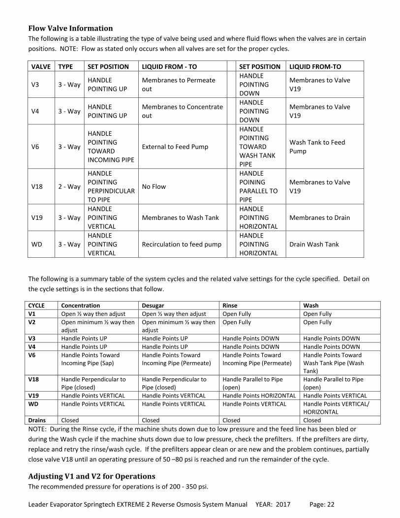
FlowValveInformationThe following is a table illustrating the type of valve being used and where fluid flows when the valves are in certain
positions. NOTE: Flow as stated only occurs when all valves are set for the proper cycles.
VALVE TYPE SET POSITION LIQUID FROM ‐ TO SET POSITION LIQUID FROM‐TO
V3 3 ‐ Way HANDLE POINTING UP
Membranes to Permeate out
HANDLE POINTING DOWN
Membranes to Valve V19
V4 3 ‐ Way HANDLE POINTING UP
Membranes to Concentrate out
HANDLE POINTING DOWN
Membranes to Valve V19
V6 3 ‐ Way
HANDLE POINTING TOWARD INCOMING PIPE
External to Feed Pump
HANDLE POINTING TOWARD WASH TANK PIPE
Wash Tank to Feed Pump
V18 2 ‐ Way
HANDLE POINTING PERPINDICULAR TO PIPE
No Flow
HANDLE POINING PARALLEL TO PIPE
Membranes to Valve V19
V19 3 ‐ Way HANDLE POINTING VERTICAL
Membranes to Wash Tank HANDLE POINTING HORIZONTAL
Membranes to Drain
WD 3 ‐ Way HANDLE POINTING VERTICAL
Recirculation to feed pump HANDLE POINTING HORIZONTAL
Drain Wash Tank
The following is a summary table of the system cycles and the related valve settings for the cycle specified. Detail on
the cycle settings is in the sections that follow.
CYCLE Concentration Desugar Rinse Wash
V1 Open ½ way then adjust Open ½ way then adjust Open Fully Open Fully
V2 Open minimum ½ way then adjust
Open minimum ½ way then adjust
Open Fully Open Fully
V3 Handle Points UP Handle Points UP Handle Points DOWN Handle Points DOWN
V4 Handle Points UP Handle Points UP Handle Points DOWN Handle Points DOWN
V6 Handle Points Toward Incoming Pipe (Sap)
Handle Points Toward Incoming Pipe (Permeate)
Handle Points Toward Incoming Pipe (Permeate)
Handle Points Toward Wash Tank Pipe (Wash Tank)
V18 Handle Perpendicular to Pipe (closed)
Handle Perpendicular to Pipe (closed)
Handle Parallel to Pipe (open)
Handle Parallel to Pipe (open)
V19 Handle Points VERTICAL Handle Points VERTICAL Handle Points HORIZONTAL Handle Points VERTICAL
WD Handle Points VERTICAL Handle Points VERTICAL Handle Points VERTICAL Handle Points VERTICAL/ HORIZONTAL
Drains Closed Closed Closed Closed
NOTE: During the Rinse cycle, if the machine shuts down due to low pressure and the feed line has been bled or
during the Wash cycle if the machine shuts down due to low pressure, check the prefilters. If the prefilters are dirty,
replace and retry the rinse/wash cycle. If the prefilters appear clean or are new and the problem continues, partially
close valve V18 until an operating pressure of 50 –80 psi is reached and run the remainder of the cycle.
AdjustingV1andV2forOperationsThe recommended pressure for operations is of 200 ‐ 350 psi.
Leader Evaporator Springtech EXTREME 2 Reverse Osmosis System Manual YEAR: 2017 Page: 23
V2 is adjusted for concentration output by flow or % sugar.
There are two methods of determining how to set the V1 and V2 valves.
Concentrate Preferred – Turn V1 to a minimum pressure and turn V2 until the desired concentration is
obtained. Adjust V1 until the pressure desired is reached. Readjust V2 until the concentration desired is
reached.
Volume Preferred – Turn V2 to a minimum and Turn V1 until the desired flow is reached. Adjust V2 until the
concentration desired is reached. Readjust V1 until the desired flow is reached.
SamplePortUseWhen using the concentrate sample port, run approximately 1 test cup of concentrate through in order to purge the
lines. Pour that cup back into the raw sap tank. Draw a second cup and sample.
The permeate sampling ports should be purged as done with the concentrate sample port. The permeate through
these ports should be sampled once per day.
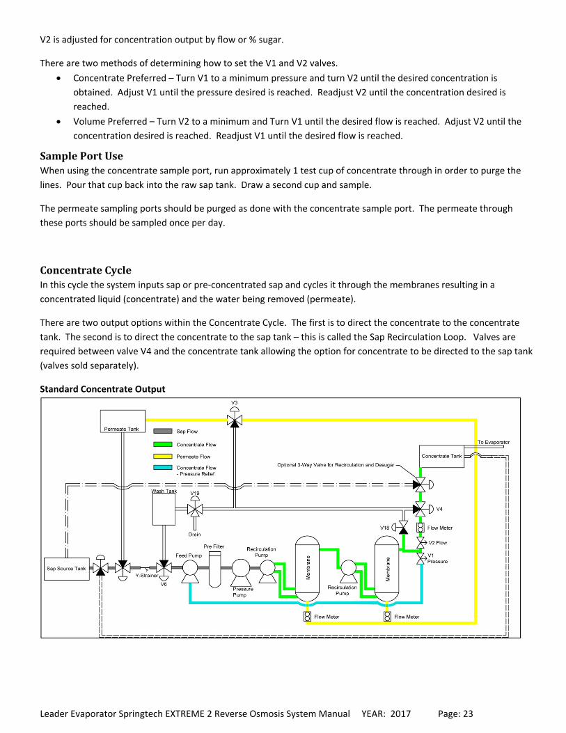
ConcentrateCycleIn this cycle the system inputs sap or pre‐concentrated sap and cycles it through the membranes resulting in a
concentrated liquid (concentrate) and the water being removed (permeate).
There are two output options within the Concentrate Cycle. The first is to direct the concentrate to the concentrate
tank. The second is to direct the concentrate to the sap tank – this is called the Sap Recirculation Loop. Valves are
required between valve V4 and the concentrate tank allowing the option for concentrate to be directed to the sap tank
(valves sold separately).
Standard Concentrate Output
Leader Evaporator Springtech EXTREME 2 Reverse Osmosis System Manual YEAR: 2017 Page: 24
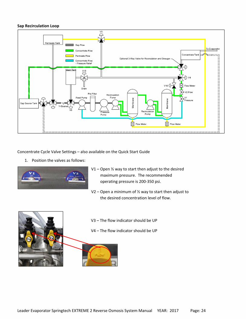
Sap Recirculation Loop
Concentrate Cycle Valve Settings – also available on the Quick Start Guide
1. Position the valves as follows:
V1 – Open ½ way to start then adjust to the desired
maximum pressure. The recommended
operating pressure is 200‐350 psi.
V2 – Open a minimum of ½ way to start then adjust to
the desired concentration level of flow.
V3 – The flow indicator should be UP
V4 – The flow indicator should be UP
Leader Evaporator Springtech EXTREME 2 Reverse Osmosis System Manual YEAR: 2017 Page: 25
2. Press the START button on the control panel. Within 30 seconds all pumps should start.
3. If the system does not continue to run due to a LOW PRESSURE ALARM;
a. Light is SOLID ‐ Repeat Step 2 up to 2 additional times. The STOP ALARM RESET button will need to be
pressed after each time.
b. Light is BLINKING – Press the STOP button to reset the alarm. Check the prefilters, changing as
necessary. Repeat Step 2.
4. If the system does not start on the third try, bleed the system. To bleed the system, open the valve on the top
of the strainer (installed before valve V6) until all the air is released from the system. Close the bleed valve.
5. When the machine has started, adjust V1 and V2 to produce the desired conditions.
DesugarCycleIn this cycle the permeate is run in a Concentrate cycle to flush accumulated sugar from the membranes. Dependent
on the operation, the Desugar process may be done in one of the following ways:
Flushing liquid for the full cycle is run to the concentrate tank
Flushing liquid for the full cycle is run to the sap tank
Flushing liquid for the part of the cycle with the highest concentration of sugar is run to the concentrate tank
then the remainder is run to the sap tank
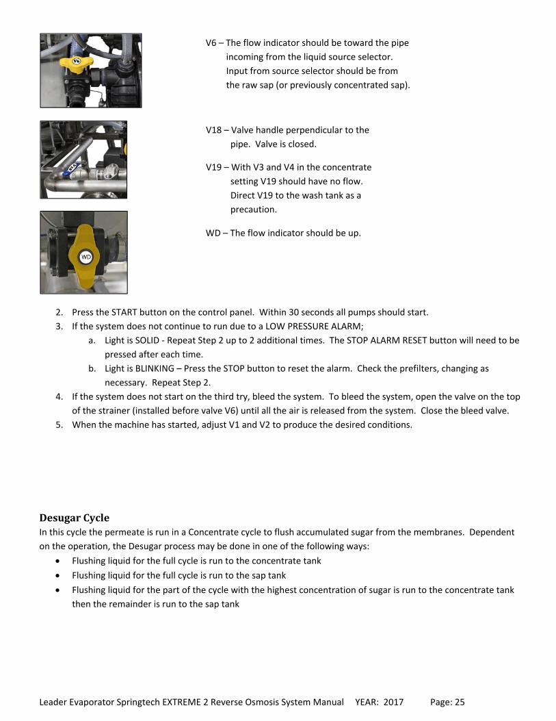
V6 – The flow indicator should be toward the pipe
incoming from the liquid source selector.
Input from source selector should be from
the raw sap (or previously concentrated sap).
V18 – Valve handle perpendicular to the
pipe. Valve is closed.
V19 – With V3 and V4 in the concentrate
setting V19 should have no flow.
Direct V19 to the wash tank as a
precaution.
WD – The flow indicator should be up.
Leader Evaporator Springtech EXTREME 2 Reverse Osmosis System Manual YEAR: 2017 Page: 26
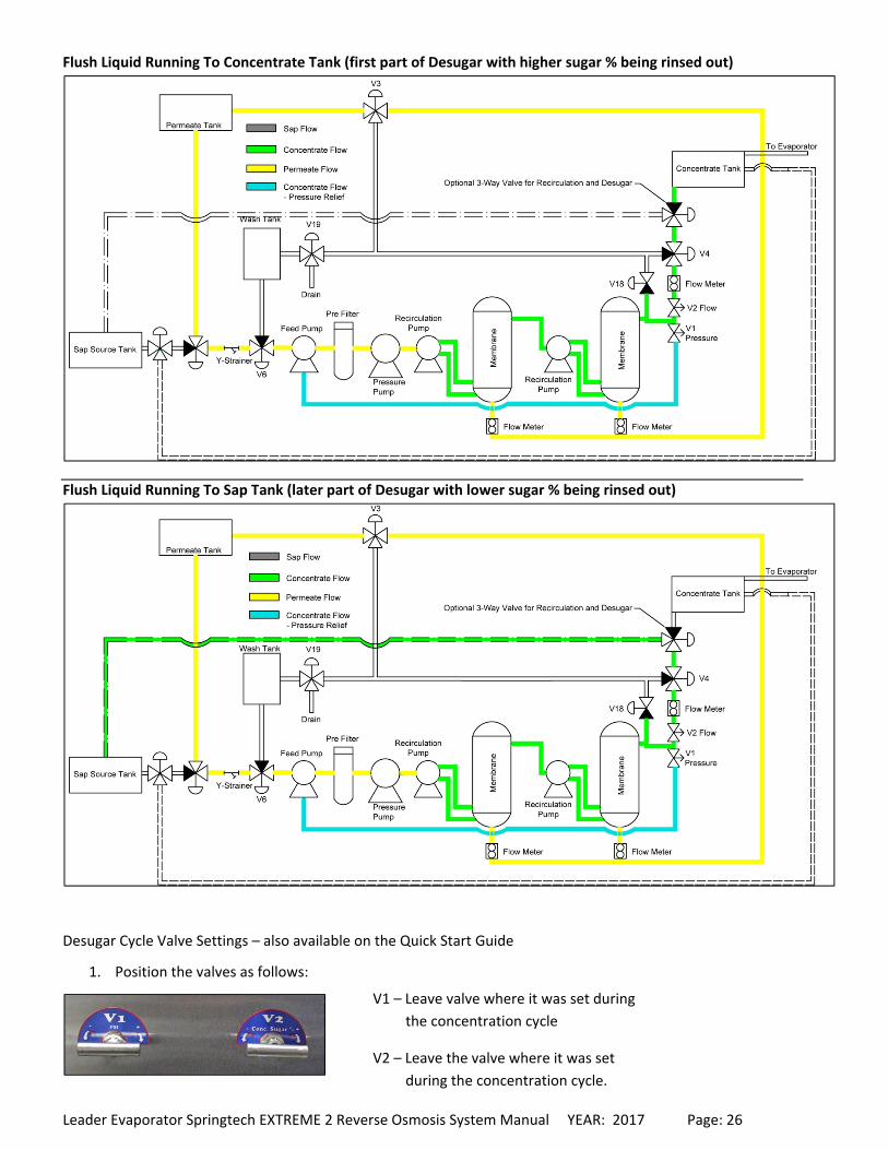
Flush Liquid Running To Concentrate Tank (first part of Desugar with higher sugar % being rinsed out)
Flush Liquid Running To Sap Tank (later part of Desugar with lower sugar % being rinsed out)
Desugar Cycle Valve Settings – also available on the Quick Start Guide
1. Position the valves as follows:
V1 – Leave valve where it was set during
the concentration cycle
V2 – Leave the valve where it was set
during the concentration cycle.
Leader Evaporator Springtech EXTREME 2 Reverse Osmosis System Manual YEAR: 2017 Page: 27
2. Press the START button on the control panel. Within 30 seconds all pumps should start.
3. If the system does not continue to run due to a LOW PRESSURE ALARM;
a. Light is SOLID ‐ Repeat Step 2 up to 2 additional times. The STOP ALARM RESET button will need to be
pressed after each time.
b. Light is BLINKING – Press the STOP button to reset the alarm. Check the prefilters, changing as
necessary. Repeat Step 2.
4. If the system does not start on the third try, bleed the system. To bleed the system, open the valve on the top
of the strainer (installed before valve V6) until all the air is released from the system. Close the bleed valve.
5. Check the concentrate sugar % level approximately every 5 minutes. The Desugar cycle should be run until the
concentrate sugar is down to at least 1% to 2%.
6. Run a rinse cycle (see page 27).
RinseCycleIn this cycle permeate is run through the system at high volume and low pressure to rinse sugar, minerals and bacteria
from the R/O. A rinse cycle is required before and after every wash cycle. At least 600 US gallons of permeate is
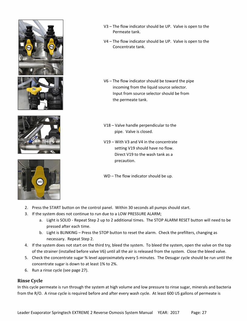
V3 – The flow indicator should be UP. Valve is open to the Permeate tank.
V4 – The flow indicator should be UP. Valve is open to the Concentrate tank.
V6 – The flow indicator should be toward the pipe
incoming from the liquid source selector.
Input from source selector should be from
the permeate tank.
V18 – Valve handle perpendicular to the
pipe. Valve is closed.
V19 – With V3 and V4 in the concentrate
setting V19 should have no flow.
Direct V19 to the wash tank as a
precaution.
WD – The flow indicator should be up.
Leader Evaporator Springtech EXTREME 2 Reverse Osmosis System Manual YEAR: 2017 Page: 28
required in a rinse following a chemical wash. Desugar and rinsing the system every 4 to 6 hours can help to maintain
higher performance rates.
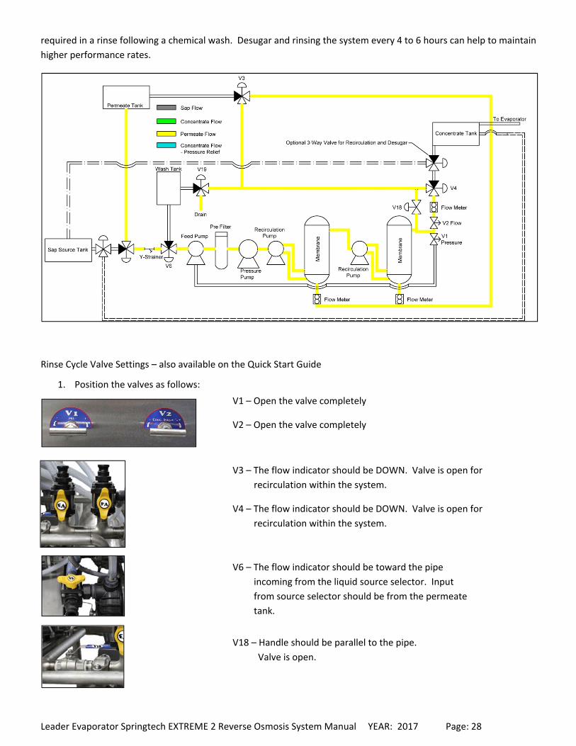
Rinse Cycle Valve Settings – also available on the Quick Start Guide
1. Position the valves as follows:
V1 – Open the valve completely
V2 – Open the valve completely
V3 – The flow indicator should be DOWN. Valve is open for
recirculation within the system.
V4 – The flow indicator should be DOWN. Valve is open for
recirculation within the system.
V6 – The flow indicator should be toward the pipe
incoming from the liquid source selector. Input
from source selector should be from the permeate
tank.
V18 – Handle should be parallel to the pipe.
Valve is open.
Leader Evaporator Springtech EXTREME 2 Reverse Osmosis System Manual YEAR: 2017 Page: 29
2. Press the START button on the control panel. Within 30 seconds all pumps should start – some air purge may
be required.
3. If the system does not continue to run due to a LOW PRESSURE ALARM;
a. Light is SOLID ‐ Repeat Step 2 up to 2 additional times. The STOP ALARM RESET button will need to be
pressed after each time.
b. Light is BLINKING – Press the STOP button to reset the alarm. Check the prefilters, changing as
necessary. Repeat Step 2.
4. If the system does not start on the third try, bleed the system. To bleed the system, open the valve on the top
of the strainer (installed before valve V6) until all the air is released from the system. Close the bleed valve.
5. If the system does not start due to a LOW PRESSURE ALARM partially close valve V18 until an operating
pressure of 50 – 80psi is reached and run the remainder of the cycle.
6. Run the Rinse cycle until a minimum of 600 US gallons of stored permeate has been used. If the Rinse is to be
followed by a Wash cycle, at the end of the rinse, fill the wash tank approximate ⅔ full by turning the V19 valve
vertically down.
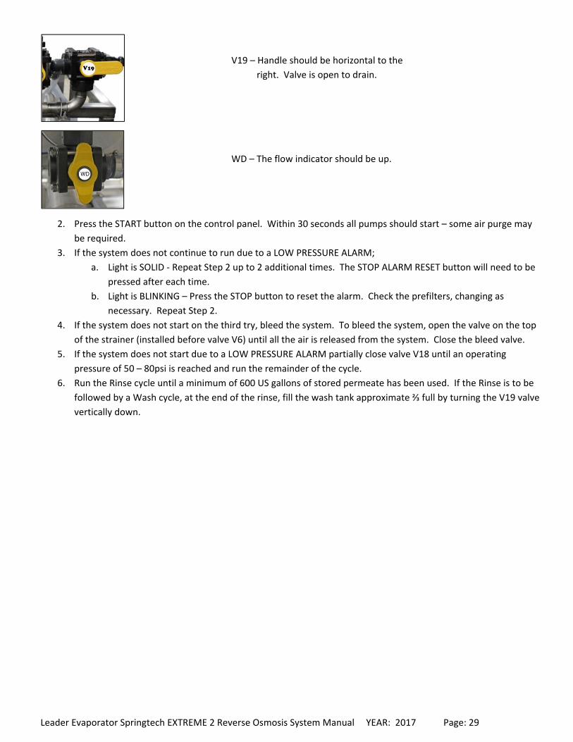
V19 – Handle should be horizontal to the
right. Valve is open to drain.
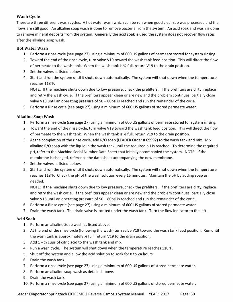
WD – The flow indicator should be up.
Leader Evaporator Springtech EXTREME 2 Reverse Osmosis System Manual YEAR: 2017 Page: 30
WashCycleThere are three different wash cycles. A hot water wash which can be run when good clear sap was processed and the
flows are still good. An alkaline soap wash is done to remove bacteria from the system. An acid soak and wash is done
to remove mineral deposits from the system. Generally the acid soak is used the system does not recover flow rates
after the alkaline soap wash.
HotWaterWash1. Perform a rinse cycle (see page 27) using a minimum of 600 US gallons of permeate stored for system rinsing.
2. Toward the end of the rinse cycle, turn valve V19 toward the wash tank feed position. This will direct the flow
of permeate to the wash tank. When the wash tank is ⅔ full, return V19 to the drain posi on.
3. Set the valves as listed below.
4. Start and run the system until it shuts down automatically. The system will shut down when the temperature
reaches 118°F.
NOTE: If the machine shuts down due to low pressure, check the prefilters. If the prefilters are dirty, replace
and retry the wash cycle. If the prefilters appear clean or are new and the problem continues, partially close
valve V18 until an operating pressure of 50 – 80psi is reached and run the remainder of the cycle.
5. Perform a Rinse cycle (see page 27) using a minimum of 600 US gallons of stored permeate water.
AlkalineSoapWash1. Perform a rinse cycle (see page 27) using a minimum of 600 US gallons of permeate stored for system rinsing.
2. Toward the end of the rinse cycle, turn valve V19 toward the wash tank feed position. This will direct the flow
of permeate to the wash tank. When the wash tank is ⅔ full, return V19 to the drain posi on.
3. At the completion of the rinse cycle, add R/O soap (LEADER Order # 69992) to the wash tank and mix. Mix
alkaline R/O soap with the liquid in the wash tank until the required pH is reached. To determine the required
pH, refer to the Machine Serial Number Data Sheet that initially accompanied the system. NOTE: If the
membrane is changed, reference the data sheet accompanying the new membrane.
4. Set the valves as listed below.
5. Start and run the system until it shuts down automatically. The system will shut down when the temperature
reaches 118°F. Check the pH of the wash solution every 15 minutes. Maintain the pH by adding soap as
needed.
NOTE: If the machine shuts down due to low pressure, check the prefilters. If the prefilters are dirty, replace
and retry the wash cycle. If the prefilters appear clean or are new and the problem continues, partially close
valve V18 until an operating pressure of 50 – 80psi is reached and run the remainder of the cycle.
6. Perform a Rinse cycle (see page 27) using a minimum of 600 US gallons of stored permeate water.
7. Drain the wash tank. The drain valve is located under the wash tank. Turn the flow indicator to the left.
AcidSoak1. Perform an alkaline Soap wash as listed above.
2. At the end of the rinse cycle (following the wash) turn valve V19 toward the wash tank feed position. Run until
the wash tank is approximately ⅔ full, return V19 to the drain posi on.
3. Add 1 – ⅓ cups of citric acid to the wash tank and mix.
4. Run a wash cycle. The system will shut down when the temperature reaches 118°F.
5. Shut off the system and allow the acid solution to soak for 8 to 24 hours.
6. Drain the wash tank.
7. Perform a rinse cycle (see page 27) using a minimum of 600 US gallons of stored permeate water.
8. Perform an alkaline soap wash as detailed above.
9. Drain the wash tank.
10. Perform a rinse cycle (see page 27) using a minimum of 600 US gallons of stored permeate water.
Leader Evaporator Springtech EXTREME 2 Reverse Osmosis System Manual YEAR: 2017 Page: 31
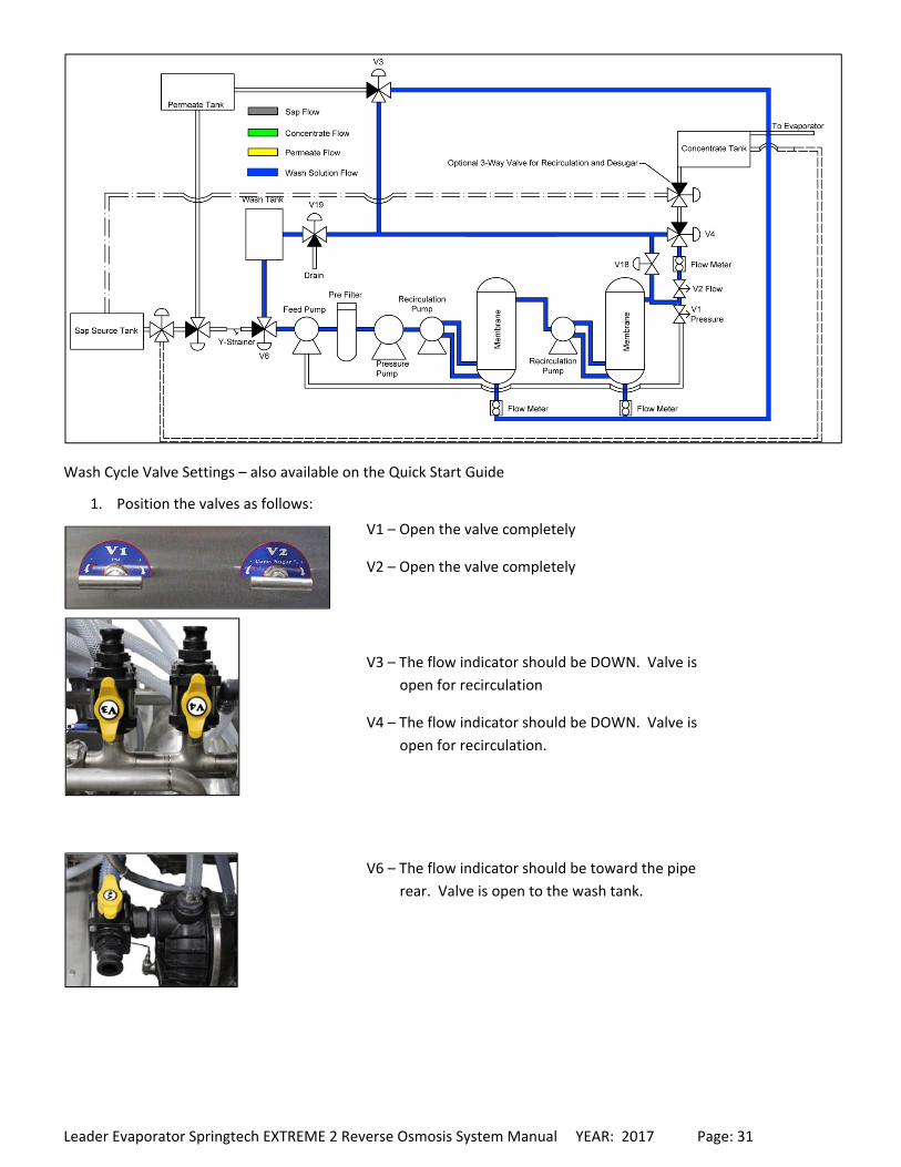
Wash Cycle Valve Settings – also available on the Quick Start Guide
1. Position the valves as follows:
V1 – Open the valve completely
V2 – Open the valve completely
V3 – The flow indicator should be DOWN. Valve is
open for recirculation
V4 – The flow indicator should be DOWN. Valve is
open for recirculation.
V6 – The flow indicator should be toward the pipe
rear. Valve is open to the wash tank.
Leader Evaporator Springtech EXTREME 2 Reverse Osmosis System Manual YEAR: 2017 Page: 32
2. Add the chemical required for the type of wash to be performed. NOTE: Ensure the wash tank is filled first.
3. Press the START button on the control panel. Within 30 seconds all pumps should start.
4. For an alkaline soap wash ‐ run the Wash cycle until the system shuts down automatically. The system
shutdown is based on the temperature of the liquid. When the liquid reaches 118°F the system will shut
down.
5. If the system does not continue to run due to a LOW PRESSURE ALARM;
c. Light is SOLID ‐ Repeat Step 2 up to 2 additional times. The STOP ALARM RESET button will need to be
pressed after each time.
d. Light is BLINKING – Press the STOP button to reset the alarm. Check the prefilters, changing as
necessary. Repeat Step 2.
6. If the system does not start on the third try, bleed the system. To bleed the system, open the valve on the top
of the strainer (installed before valve V6) until all the air is released from the system. Close the bleed valve.
7. If the system does not start due to a LOW PRESSURE ALARM partially close valve V18 until an operating
pressure of 50 – 80psi is reached and run the remainder of the cycle.
8. Press the STOP ALARM RESET button to reset the alarm.
9. Open the wash tank drain valve to drain the wash tank. When the wash tank is
empty, return the drain valve to the recirculation position.
10. Run a rinse cycle (see page 27) using a minimum of 600 US gallons of permeate from the permeate storage
tank.
11. Do a permeability test (see page 19). If the test is good, continue the rinse cycle with any additional permeate.
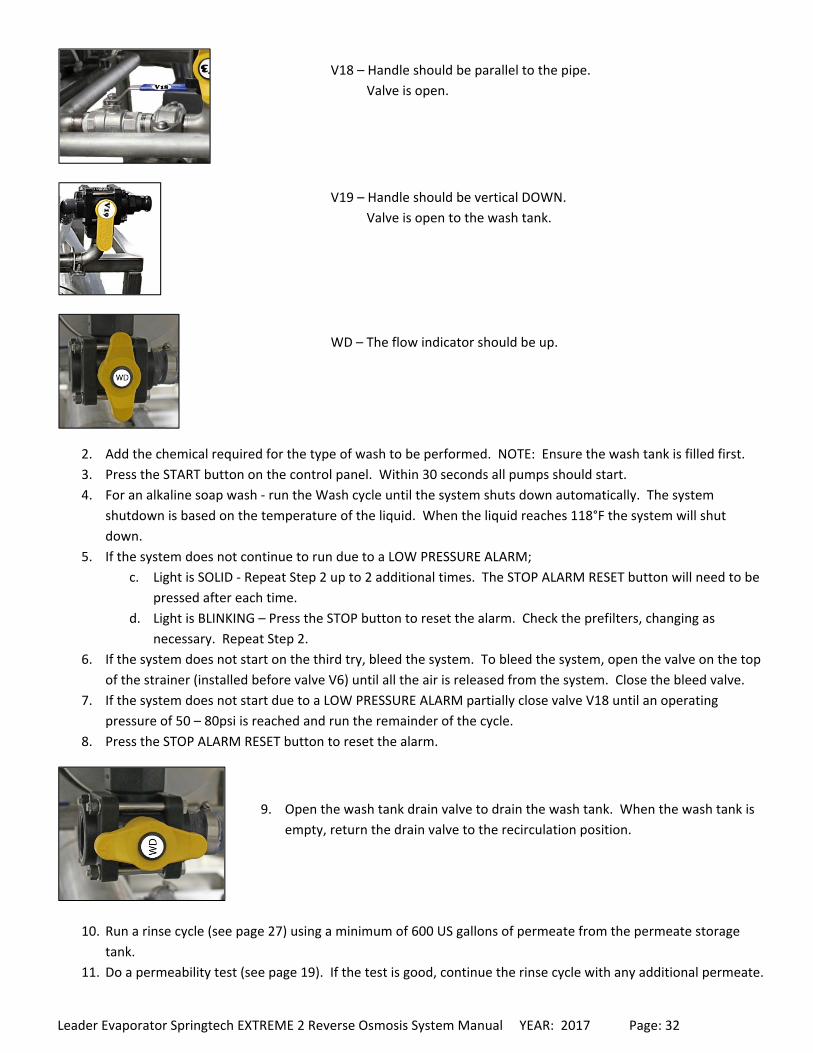
V18 – Handle should be parallel to the pipe.
Valve is open.
V19 – Handle should be vertical DOWN.
Valve is open to the wash tank.
WD – The flow indicator should be up.
Leader Evaporator Springtech EXTREME 2 Reverse Osmosis System Manual YEAR: 2017 Page: 33
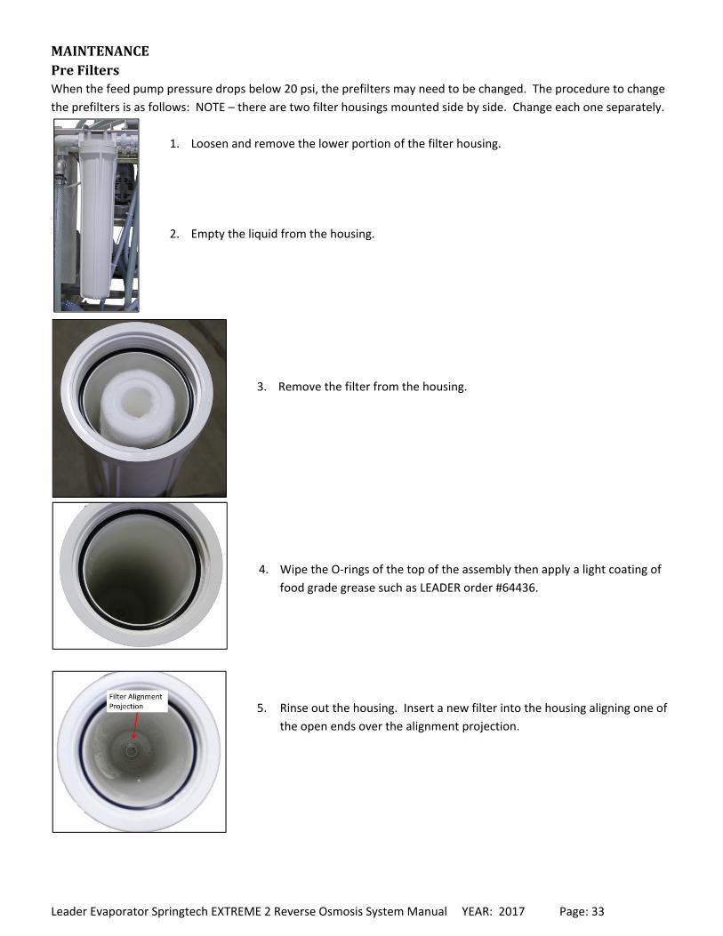
MAINTENANCEPreFiltersWhen the feed pump pressure drops below 20 psi, the prefilters may need to be changed. The procedure to change
the prefilters is as follows: NOTE – there are two filter housings mounted side by side. Change each one separately.
1. Loosen and remove the lower portion of the filter housing.
2. Empty the liquid from the housing.
3. Remove the filter from the housing.
4. Wipe the O‐rings of the top of the assembly then apply a light coating of
food grade grease such as LEADER order #64436.
5. Rinse out the housing. Insert a new filter into the housing aligning one of
the open ends over the alignment projection.

Leader Evaporator Springtech EXTREME 2 Reverse Osmosis System Manual YEAR: 2017 Page: 34
6. Bring the lower filter housing, with the filter installed, up to the underside
of the top of the filter housing on the system. Carefully align the open top
of the filter with the alignment projection in the top of the filter housing.
Thread the bottom of the housing onto the top of the housing and securely
hand tighten.
MembraneRemovalandInstallationNOTE: Membrane surfaces could produce splinters during handling. It is recommended clean leather gloves be worn
when handling membranes.
Removal
1. Stop the system by pressing the STOP button.
2. Position valve V6 to the wash position.
3. Set valves V3 and V4 in a rinse cycle position.
4. Open the drain of the membrane housing to be changed. Allow to the membrane to drain until empty.
5. Disconnect the permeate line quick coupler from the end of the membrane
housing. Quick couplers are located on the right side of the membrane
housing.
6. Carefully move the permeate pipe to the side.
7. Remove the bolts from the metal clamp between the top of the membrane
housing and the recirculation pump.
8. Slide the gasket rubber to the pipe on the pump side of the connection.

Leader Evaporator Springtech EXTREME 2 Reverse Osmosis System Manual YEAR: 2017 Page: 35
9. Using (2) ‐ 9/16” wrenches remove the bolts fastening the end of the
membrane housing to the body of the membrane housing.
10. Remove membrane housing cap from the membrane.
11. Remove the alignment coupling from the end of the membrane.
12. Remove the membrane from the housing. If the membrane plug on the other end of the membrane
is attached, remove it. Note – the membrane will contain liquid.
Installation
1. Inspect and replace if necessary the four (4) O‐rings of the membrane plug.
Lightly lubricate the O‐rings with permeate or non‐chlorinated weel or spring
water then slide the plug into the membrane.
Leader Evaporator Springtech EXTREME 2 Reverse Osmosis System Manual YEAR: 2017 Page: 36
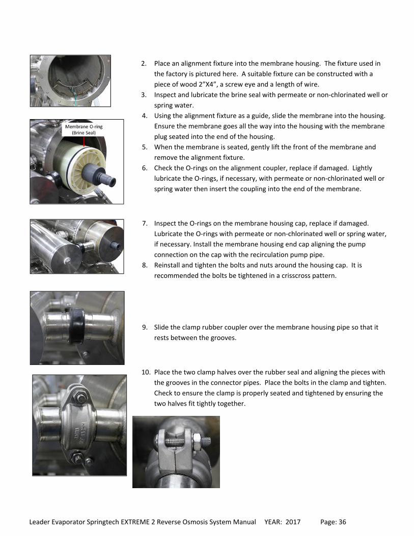
2. Place an alignment fixture into the membrane housing. The fixture used in
the factory is pictured here. A suitable fixture can be constructed with a
piece of wood 2”X4”, a screw eye and a length of wire.
3. Inspect and lubricate the brine seal with permeate or non‐chlorinated well or
spring water.
4. Using the alignment fixture as a guide, slide the membrane into the housing.
Ensure the membrane goes all the way into the housing with the membrane
plug seated into the end of the housing.
5. When the membrane is seated, gently lift the front of the membrane and
remove the alignment fixture.
6. Check the O‐rings on the alignment coupler, replace if damaged. Lightly
lubricate the O‐rings, if necessary, with permeate or non‐chlorinated well or
spring water then insert the coupling into the end of the membrane.
7. Inspect the O‐rings on the membrane housing cap, replace if damaged.
Lubricate the O‐rings with permeate or non‐chlorinated well or spring water,
if necessary. Install the membrane housing end cap aligning the pump
connection on the cap with the recirculation pump pipe.
8. Reinstall and tighten the bolts and nuts around the housing cap. It is
recommended the bolts be tightened in a crisscross pattern.
9. Slide the clamp rubber coupler over the membrane housing pipe so that it
rests between the grooves.
10. Place the two clamp halves over the rubber seal and aligning the pieces with
the grooves in the connector pipes. Place the bolts in the clamp and tighten.
Check to ensure the clamp is properly seated and tightened by ensuring the
two halves fit tightly together.
Leader Evaporator Springtech EXTREME 2 Reverse Osmosis System Manual YEAR: 2017 Page: 37
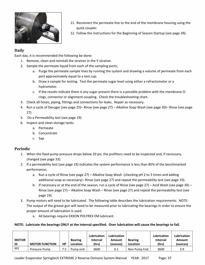
11. Reconnect the permeate line to the end of the membrane housing using the
quick coupler.
12. Follow the instructions for the Beginning of Season Startup (see page 39).
DailyEach day, it is recommended the following be done:
1. Remove, clean and reinstall the strainer in the Y‐strainer.
2. Sample the permeate liquid from each of the sampling ports;
a. Purge the permeate sample lines by running the system and drawing a volume of permeate from each
port approximately equal to a test cup.
b. Draw a sample for testing. Test the permeate sugar level using either a refractometer or a
hydrometer.
c. If the results indicate there is any sugar present there is a possible problem with the membrane O‐
rings, connector or alignment coupling. Check the troubleshooting chart.
3. Check all hoses, piping, fittings and connections for leaks. Repair as necessary.
4. Run a cycle of Desugar (see page 25)– Rinse (see page 27) – Alkaline Soap Wash (see page 30)– Rinse (see page
27)
5. Do a Permeability test (see page 19)
6. Inspect and clean storage tanks
a. Permeate
b. Concentrate
c. Sap
Periodic1. When the feed pump pressure drops below 20 psi, the prefilters need to be inspected and, if necessary,
changed (see page 33).
2. If a permeability test (see page 19) indicates the system performance is less than 85% of the benchmarked
performance;
a. Run a cycle of Rinse (see page 27) – Alkaline Soap Wash (checking pH 2 to 3 times and adding
additional soap as necessary)– Rinse (see page 27) and repeat the permeability test (see page 19).
b. If necessary or at the end of the season, run a cycle of Rinse (see page 27) – Acid Wash (see page 30) –
Rinse (see page 27) – Alkaline Soap Wash – Rinse (see page 27) and repeat the permeability test (see
page 19).
3. Pump motors will need to be lubricated. The following table describes the lubrication requirements. NOTE:
The output of the grease gun will need to be measured prior to lubricating the bearings in order to ensure the
proper amount of lubrication is used.
a. All bearings require EXXON POLYREX EM lubricant.
NOTE: Lubricate the bearings ONLY at the interval specified. Over lubrication will cause the bearings to fail.
MOTOR ID MOTOR FUNCTION HP
Bearing Location
Lubrication Interval (hrs)
Lubrication Amount (ounces)
Bearing Location
Lubrication Interval (hrs)
Lubrication Amount (ounces)
M2 Pressure Pump 7.5 Pump end 3600 6.1 Non Pump End 3600 3.9
Leader Evaporator Springtech EXTREME 2 Reverse Osmosis System Manual YEAR: 2017 Page: 38
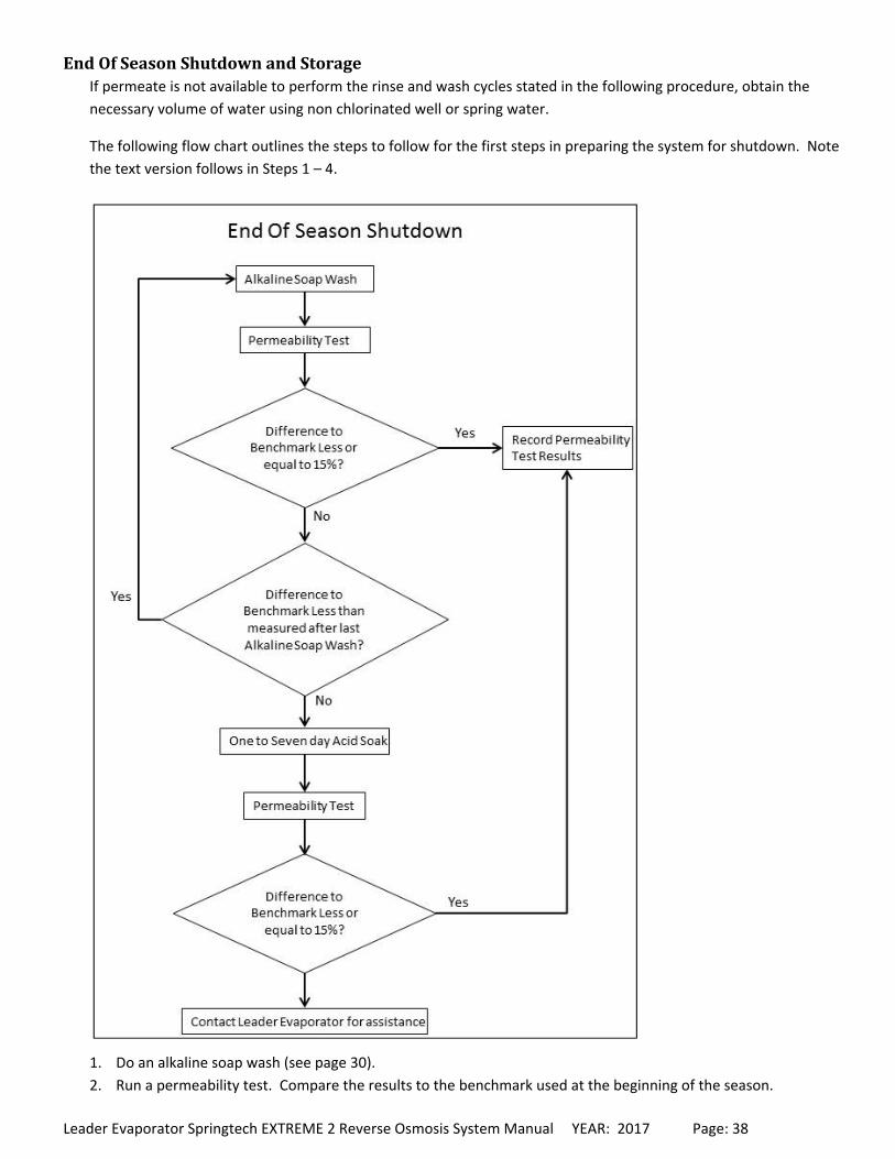
EndOfSeasonShutdownandStorageIf permeate is not available to perform the rinse and wash cycles stated in the following procedure, obtain the
necessary volume of water using non chlorinated well or spring water.
The following flow chart outlines the steps to follow for the first steps in preparing the system for shutdown. Note
the text version follows in Steps 1 – 4.
1. Do an alkaline soap wash (see page 30).
2. Run a permeability test. Compare the results to the benchmark used at the beginning of the season.
Leader Evaporator Springtech EXTREME 2 Reverse Osmosis System Manual YEAR: 2017 Page: 39
a. If the results show a difference of greater than 15% and the difference in the percentage is less than
the previous alkaline soap wash cycle, repeat the alkaline soap wash cycle.
b. If the results show a difference greater than 15% and there was no improvement as compared to the
previous alkaline soap wash cycle continue to the next step – Acid Soak Cycle.
c. If the difference is 15% of less, continue with Step 4.
3. Do an acid soak cycle (see page 30) allow the machine to soak for 1 to 7 days starting the system on the first
day and allowing it to run to the auto shutdown temperature of 118°F. Run the system to temperature the
same way on the last day of the cycle. Run a permeability test (see page 19).
4. If the difference in results is 15% or less – record the permeability test results. If the results are greater than
15%, contact Leader Evaporator for assistance.
5. Drain the wash tank (valve WD) then close the drain.
6. In the wash tank mix:
a. 9 US gallons of permeate
b. 2 US gallons of glycol
c. 2 teaspoons of membrane preservative
7. Set the system valves for a wash cycle (see page 30) and run the system for 15 minutes. Drain the wash tank.
8. Empty then reinstall the prefilter housing.
9. Drain the pumps then close all drains.
10. Maintain a temperature minimum of 40°F to 50°F in the area where the system is stored. Do not allow the
system to freeze.
NOTE: If there is a possibility of the system freezing, drain all the fluid from the system.
11. Drain and clean all storage tanks. Cover them in order to keep dirt and pests out. NOTE: If permeate is not
available for cleaning, use non‐chlorinated well or spring water.
BeginningofSeasonStartupAs permeate will not be available to perform the rinse and wash cycles stated in the following procedure, obtain
the necessary volume of water using non chlorinated well or spring water.
1. Connect the reverse osmosis system to the concentrate, permeate and feed lines.
2. Replace prefilters.
3. Open the control box by unfastening the latches/buckles of the left side then opening the door carefully to the
right.
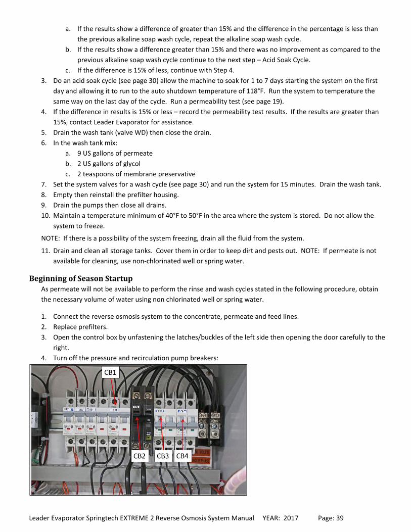
4. Turn off the pressure and recirculation pump breakers:
Leader Evaporator Springtech EXTREME 2 Reverse Osmosis System Manual YEAR: 2017 Page: 40
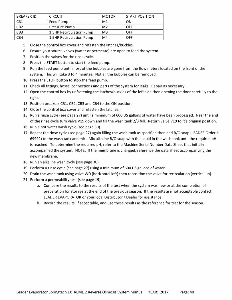
BREAKER ID CIRCUIT MOTOR START POSITION
CB1 Feed Pump M1 ON
CB2 Pressure Pump M2 OFF
CB3 1.5HP Recirculation Pump M3 OFF
CB4 1.5HP Recirculation Pump M4 OFF
5. Close the control box cover and refasten the latches/buckles.
6. Ensure your source valves (water or permeate) are open to feed the system.
7. Position the valves for the rinse cycle.
8. Press the START button to start the feed pump.
9. Run the feed pump until most of the bubbles are gone from the flow meters located on the front of the
system. This will take 3 to 4 minutes. Not all the bubbles can be removed.
10. Press the STOP button to stop the feed pump.
11. Check all fittings, hoses, connections and parts of the system for leaks. Repair as necessary.
12. Open the control box by unfastening the latches/buckles of the left side then opening the door carefully to the
right.
13. Position breakers CB1, CB2, CB3 and CB4 to the ON position.
14. Close the control box cover and refasten the latches.
15. Run a rinse cycle (see page 27) until a minimum of 600 US gallons of water have been processed. Near the end
of the rinse cycle turn valve V19 down and fill the wash tank 2/3 full. Return valve V19 to it’s original position.
16. Run a hot water wash cycle (see page 30).
17. Repeat the rinse cycle (see page 27) again filling the wash tank as specified then add R/O soap (LEADER Order #
69992) to the wash tank and mix. Mix alkaline R/O soap with the liquid in the wash tank until the required pH
is reached. To determine the required pH, refer to the Machine Serial Number Data Sheet that initially
accompanied the system. NOTE: If the membrane is changed, reference the data sheet accompanying the
new membrane.
18. Run an alkaline wash cycle (see page 30).
19. Perform a rinse cycle (see page 27) using a minimum of 600 US gallons of water.
20. Drain the wash tank using valve WD (horizontal left) then reposition the valve for recirculation (vertical up).
21. Perform a permeability test (see page 19).
a. Compare the results to the results of the test when the system was new or at the completion of
preparation for storage at the end of the previous season. If the results are not acceptable contact
LEADER EVAPORATOR or your local Distributor / Dealer for assistance.
b. Record the results, if acceptable, and use these results as the reference for test for the season.
Leader Evaporator Springtech EXTREME 2 Reverse Osmosis System Manual YEAR: 2017 Page: 41
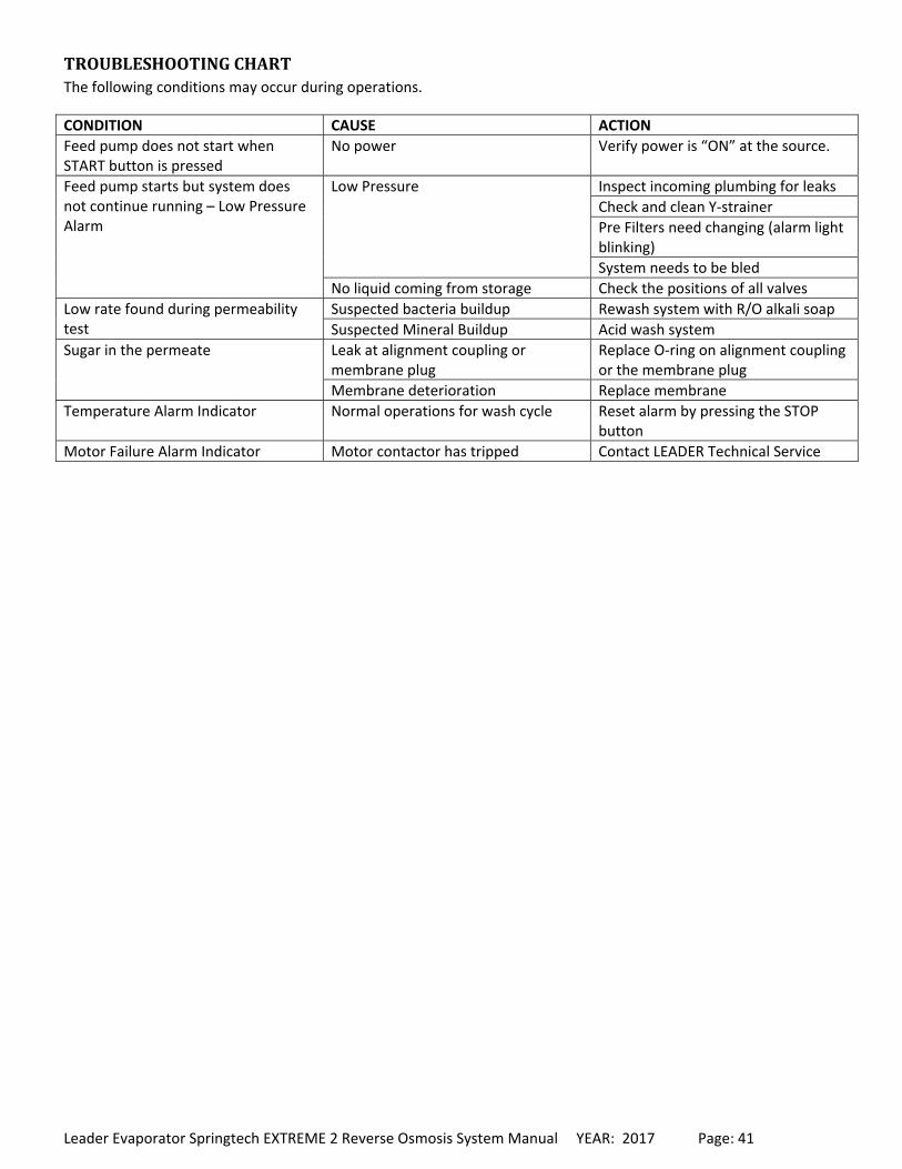
TROUBLESHOOTINGCHARTThe following conditions may occur during operations.
CONDITION CAUSE ACTION
Feed pump does not start when START button is pressed
No power Verify power is “ON” at the source.
Feed pump starts but system does not continue running – Low Pressure Alarm
Low Pressure Inspect incoming plumbing for leaks
Check and clean Y‐strainer
Pre Filters need changing (alarm light blinking)
System needs to be bled
No liquid coming from storage Check the positions of all valves
Low rate found during permeability test
Suspected bacteria buildup Rewash system with R/O alkali soap
Suspected Mineral Buildup Acid wash system
Sugar in the permeate Leak at alignment coupling or membrane plug
Replace O‐ring on alignment coupling or the membrane plug
Membrane deterioration Replace membrane
Temperature Alarm Indicator Normal operations for wash cycle Reset alarm by pressing the STOP button
Motor Failure Alarm Indicator Motor contactor has tripped Contact LEADER Technical Service
Leader Evaporator Springtech EXTREME 2 Reverse Osmosis System Manual YEAR: 2017 Page: 42
ATTACHMENT#1–ELECTRICALSCHEMATICS

Leader Evaporator Springtech EXTREME 2 Reverse Osmosis System Manual YEAR: 2017 Page: 43
ATTACHMENT#2–OPERATIONDATALOGSHEETWater Removal % = ((permeate 1 flow + permeate 2 flow) / (permeate 1 flow + permeate 2 flow + concentrate flow))*100
GPH Processed = (permeate 1 flow + permeate 2 flow + concentrate flow)*60
SPRINGTECH EXTREME 2 OPERATIONS DATA
DATE
ACTIVITY (C or T) SUGAR CONCENTRATION
SAP CONCENTRATE
FLOW (gpm) PERMEATE 1 PERMEATE 2 CONCENTRATE
TEMPERATURE PRESSURE (psi) FEED PUMP
MEMBRANE WATER REMOVAL % GPH PROCESSED
DATE
ACTIVITY (C or T) SUGAR CONCENTRATION
SAP CONCENTRATE
FLOW (gpm) PERMEATE 1 PERMEATE 2 CONCENTRATE
TEMPERATURE PRESSURE (psi) FEED PUMP
MEMBRANE WATER REMOVAL % GPH PROCESSED
DATE
ACTIVITY (C or T) SUGAR CONCENTRATION
SAP CONCENTRATE
FLOW (gpm) PERMEATE 1 PERMEATE 2 CONCENTRATE
TEMPERATURE PRESSURE (psi) FEED PUMP
MEMBRANE WATER REMOVAL % GPH PROCESSED

Leader Evaporator Springtech EXTREME 2 Reverse Osmosis System Manual YEAR: 2017 Page: 44
ATTACHMENT#3–MEMBRANEPERMEABILITYTESTSHEET

Leader Evaporator Springtech EXTREME 2 Reverse Osmosis System Manual YEAR: 2017 Page: 45
ATTACHMENT#4–WARRANTYINFORMATION
Leader Evaporator Manufacturer’s Warranty For Springtech Extreme Reverse Osmosis
Machines
Leader Evaporator Co., Inc. warranties our Springtech Extreme line of Reverse Osmosis Machines against any manufacturer defects for a period of two years from the date of purchase. This warranty is at the discretion of the manufacturer, Leader Evaporator Co., Inc., to be replaced or repaired, as necessary. All replaced parts become the manufacturer’s property. Leader Evaporator Co., Inc. shall not be held responsible for any damage or injury arising from negligence, abuse, improper handling or installation.
Leader Evaporator Co., Inc. 49 Jonergin Drive
Swanton, VT 05488 Tel: (802) 868-5444 Fax: (802) 868-5445
www.leaderevaporator.com