external interfaces and the connector board interfaces specified originally 2x camera link camera2x...
Post on 19-Dec-2015
216 views
TRANSCRIPT
External Interfaces andthe Connector Board
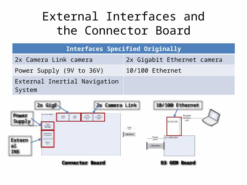
Interfaces Specified Originally
2x Camera Link camera 2x Gigabit Ethernet camera
Power Supply (9V to 36V) 10/100 Ethernet
External Inertial Navigation System
Power Supply
External INS
2x GigE 2x Camera Link 10/100 Ethernet
Connector Board D3 OEM Board

External Interfaces andthe Connector Board
Final Interfaces Specified
2x Camera Link camera 2x GigE camera
Power Supply (9V to 36V) 10/100 Ethernet
External Inertial Navigation System RCA output
USB port
PowerSupply
2x Camera Link
External INS
RCA output
USB port
2x GigE
10/100 Ethernet
Connector Panel
External Interfaces andthe Connector Board
• Goal:– All interfaces routed through and mounted on the
Connector Board• Reality:– Various different mountings and routings
necessary

Interface Routing andConnector Mounting
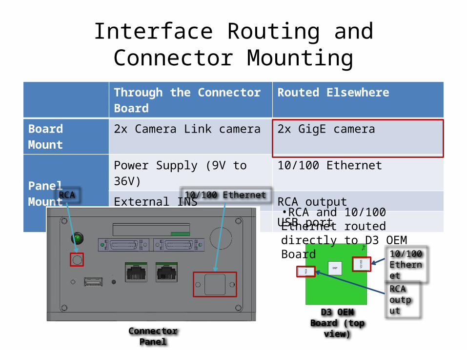
Through the Connector Board Routed Elsewhere
Board Mount 2x Camera Link camera 2x GigE camera
Panel Mount
Power Supply (9V to 36V) 10/100 Ethernet
External INS RCA output
USB port
Power Supply2x Camera Link External INS
•2x Camera Link = nearly full width of Connector Board
Connector Panel

Interface Routing andConnector Mounting
Through the Connector Board Routed Elsewhere
Board Mount 2x Camera Link camera 2x GigE camera
Panel Mount
Power Supply (9V to 36V) 10/100 Ethernet
External INS RCA output
USB port
2x GigE
•GigE mounted on FPGA Board
FPGA Board (bottom view)Connector Panel
Interface Routing andConnector Mounting
Through the Connector Board Routed Elsewhere
Board Mount 2x Camera Link camera 2x GigE camera
Panel Mount
Power Supply (9V to 36V) 10/100 Ethernet
External INS RCA output
USB port
RCA output
10/100Ethernet
D3 OEM Board (top view)
•RCA and 10/100 Ethernet routed directly to D3 OEM Board
RCA
Connector Panel
10/100 Ethernet

Through the Connector Board Routed Elsewhere
Board Mount 2x Camera Link camera 2x GigE camera
Panel Mount
Power Supply (9V to 36V) 10/100 Ethernet
External INS RCA output
USB port
Interface Routing andConnector Mounting
USB port
Connector Panel
•USB routed directly to internal GNSS receiver
The Connector Board
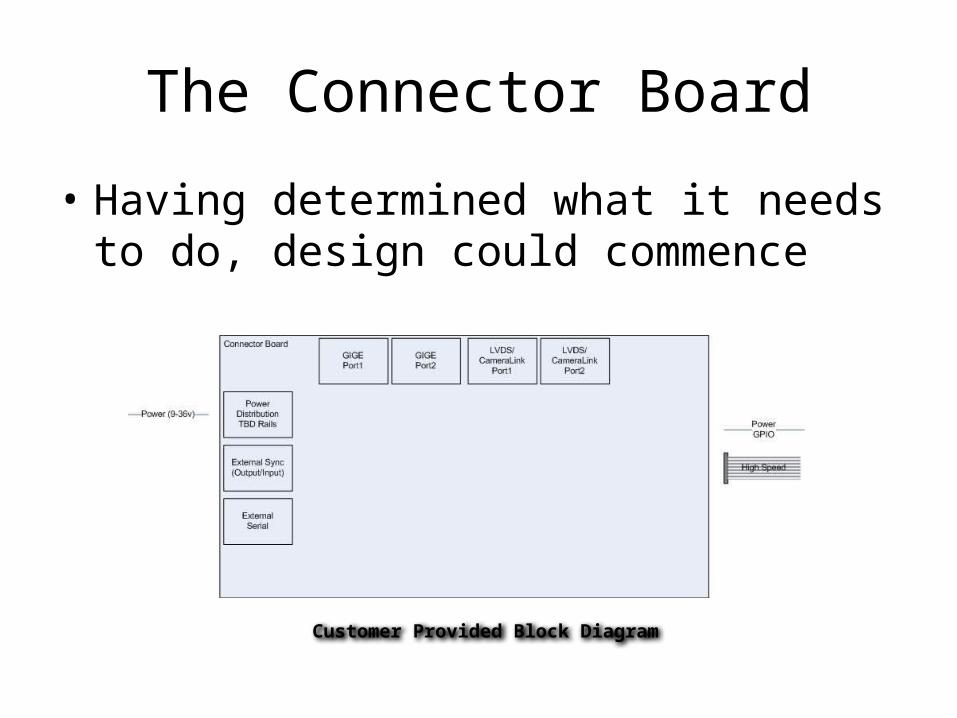
• Having determined what it needs to do, design could commence
Customer Provided Block Diagram

Connector Board Design:Functional Block Diagram

Connector Board Design:Scale Diagram
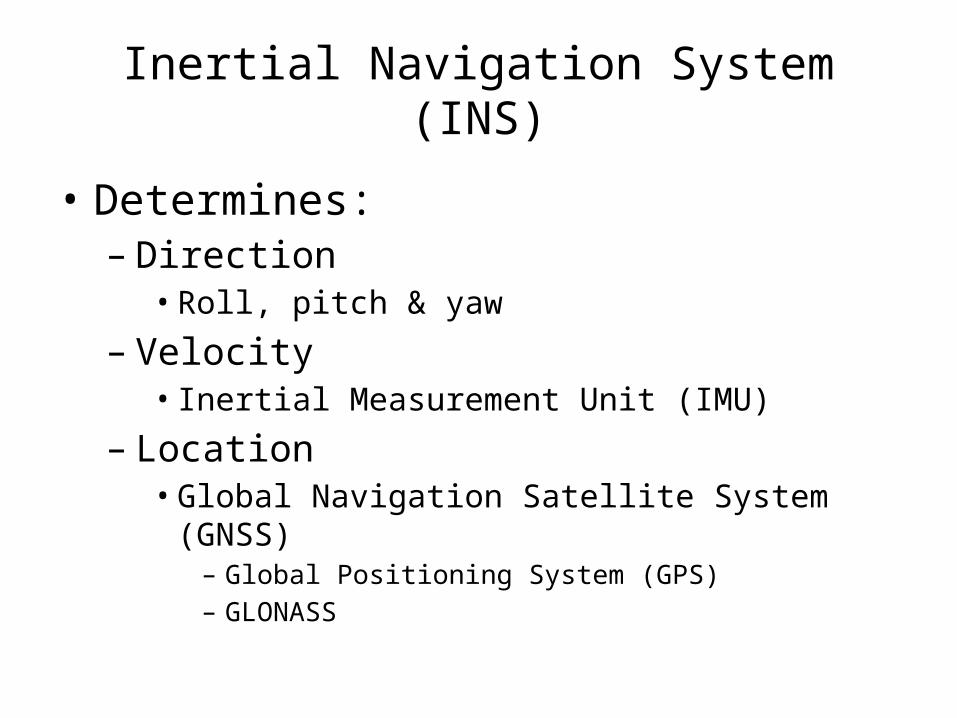
Inertial Navigation System (INS)
• Determines:– Direction• Roll, pitch & yaw
– Velocity • Inertial Measurement Unit (IMU)
– Location• Global Navigation Satellite System (GNSS)
– Global Positioning System (GPS)– GLONASS

Global Navigation Satellite System
• Customer Specified– NovAtel OEMV-2 or OEMV-3• RS-232 interface• Different power requirements
OEMV-2: 3.3 +5%/-3% VDC OEMV-3: 4.5 to 18 VDC
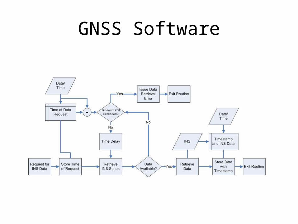
GNSS Software