external gear motors - airline hydraulics · nbr = m fpm = p nbr, ... din en iso 8674 ... external...
TRANSCRIPT

External Gear Motors
AZMF ... , AZMN ... , AZMG ...
RE 14 026/01.05Replaces: 1 987 760 101/01.99
Model F = 8 ... 22.5 cm3/revN = 25 und 28 cm3/revG = 22.5 ... 45 cm3/rev
Contents Page
Function 2
Overview 3
Ordering code 4
Drive shaft 6
Front cover 7
Port connections 8
Motors with integral Valves and Sensors 9
Design calculations for Motors 10
Diagrams 10
Specifications 14
Drive arrangement 16
Connectors 17
Dimension Drawings 19
Notes 40
General
Rexroth external gear motors are produced in 3 different models,
with different displacements being produced by means of gears of
differing widths.
Different versions of motors are achieved by the use of different
flanges, shafts, valves and integrated speed sensors.
Features
– High pressures combined with small size and low weight
– Large speed ranges
– Broad viscosity and temperature ranges
– Reversible motors for 2- and 4-quadrant operation
Fields of application
– Road construction machines as road rollers and pavers
– Agricultural machines and forestry technology as harvesters and
forestry machines
– Street vehicles such as busses, trucks and special vehicles
and above all in hydrostatic fan drives.
Industrial Electric Drives Linear Motion and Service MobileHydraulics and Controls Assembly Technologies Pneumatics Automation Hydraulics
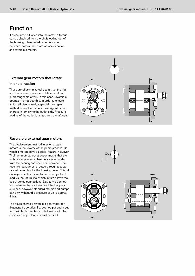
FunctionIf pressurized oil is fed into the motor, a torque
can be obtained from the shaft leading out of
the housing. Here, a distinction is made
between motors that rotate on one direction
and reversible motors.
2/40 Bosch Rexroth AG Mobile Hydraulics External gear motors RE 14 026/01.05
External gear motors that rotate
in one direction
These are of asymmetrical design, i.e. the high
and low pressure sides are defined and not
interchangeable at will. In this case, reversible
operation is not possible. In order to ensure
a high efficiency level, a special running-in
method is used for motors. Leakage oil is dis-
charged internally to the outlet side. Pressure
loading of the outlet is limited by the shaft seal.
Reversible external gear motors
The displacement method in external gear
motors is the reverse of the pump process. Re-
versible motors have a special feature, however.
Their symmetrical construction means that the
high or low pressure chambers are separate
from the bearing and shaft seal chamber. The
resulting leakage oil is routed through a sepa-
rate oil drain gland in the housing cover. This oil
drainage enables the motor to be subjected to
load via the return line, which in turn allows the
use of series connections. Due to the connec-
tion between the shaft seal and the low-pres-
sure end, however, standard motors and pumps
can only withstand a pressure of up to approx.
3 bar.
The figure shows a reversible gear motor for
4-quadrant operation, i.e. both output and input
torque in both directions. (Hydraulic motor be-
comes a pump if load reversal occurs.)
pA

External gear motors RE 14 026/01.05 Mobile Hydraulics Bosch Rexroth AG 3/40
Version Page
19
20
21
22
23
Version Page
24
25
26
27
28
Version Page
29
30
31
32
34
Product overview “Model F” preferential range
Version Page
35
Version Page
36
Product overview “Model N” preferential range
Version Page
39
Version Page
37
Version Page
38
Product overview “Model G” preferential range

4/40 Bosch Rexroth AG Mobile Hydraulics External gear motors RE 14 026/01.05
Ordering codeExternal Gear Motors Model “F”
AZ M F 1x– – 022 R C B 20 M B 200xx S0001
Function
M = Motor
Series
1x = Standard bearing
Size (F)
8.0 cm3/rev = 008
11.0 cm3/rev = 011
14.0 cm3/rev = 014
16.0 cm3/rev = 016
19.0 cm3/rev = 019
22.5 cm3/rev = 022
Direction of rotation
Right = R
Left = L
Universal = U
Drive shafts Front cover Port connections
C B
T
A
P
B P
N
F
S
Tapered keyed
shaft 1 : 5B
suitable front cover
Tang drive
Square flange
Centring Ø 80 mm
P2-bolt mounting
Centring Ø 50 mm
O Square flange
Centring Ø 36.47 mm
AOutboard bearing
Ø 80 mm, Type 1
Spline shaft
DIN 5482 B 17 x 14
Tapered keyed
shaft 1 : 5
for flange A
Special
design*)
Valve adjustment
PRV 200 bar = 200 xx
PRV = 180 xx
Rear cover
Standard = B
PRV = G
drain oil line
connection (axial) = L
PRV excess flow
internal = D
Seals
NBR = M
FPM = P
NBR, WDR in FPM = K
20Rectangular
flange
30
N2-bolt mounting
Centring Ø 50 mm
T4-bolt mounting
Ø 52 mm, with O-ring
*) The special equipments partly contained
on the pages 20–35, are not considered in
the representation of the ordering code.
Rectangular
flange
–

External gear motors RE 14 026/01.05 Mobile Hydraulics Bosch Rexroth AG 5/40
Ordering code External Gear Motors Model “N”
AZ M N 1x– – 020 R C B 20 M B S0001
Function
M = Motor
Series
1x = Standard bearing
Size (N)
25.0 cm3/rev = 025
28.0 cm3/rev = 028
Direction of rotation
Right = R
Left = L
Drive shafts Front cover Port connections
C BTapered keyed
shaft 1 : 5B
suitable front cover
Square flange
Centring Ø 100 mm
Special
design
Rear cover
Standard = B
Special design = X
Seals
NBR = M
FPM = P
20Rectangular
flange
–
External Gear Motors Model “G”
AZ M G 1x– – 022 R C B 20 M B S0001
Function
M = Motor
Model
G = 22.5...56 cm3/rev
Size (G)
22.5 cm3/rev = 022
28.0 cm3/rev = 028
32.0 cm3/rev = 032
45.0 cm3/rev = 045
Direction of rotation
Right = R
Left = L
Universal = U
Drive shafts Front cover Port connections
C B
MN
Tapered keyed
shaft 1 : 5B
suitable front cover
Tang drive
Square flange
Centring Ø 105 mm
2-bolt mounting
Ø 52 mm, with O-ringM
Special
design
Rear cover
Standard = B
Special design = X
Seals
NBR = M
NBR, WDR in FPM = K
20Rectangular
flange
–

6/40 Bosch Rexroth AG Mobile Hydraulics External gear motors RE 14 026/01.05
Drive shaft model “F” Drive shaft model “N”
Drive shaft model “G”
3x5 DIN 6888
DIN 936-M12x1.5-m-06
DIN 128-A12-FSt
= 50+10 Nm
17
1:5
1.8
5°42
'38"
7.8± 0.35
38± 0.6
Ø17
− 0.0
27
C
2.7+0.5
6.5+0.3
Ø17
−0
.02
7
−0
.02
58
−0
.08
3
N
Motor without shaft seal
Ø16
.5−
0.2
7
23.5−0.8
(22±0.4)
2± 0.5
min. 14.8usable shaftlength
B 17x14DIN 5482tooth thickness sw = 3.200−0.030
F
1:5
4x6.5 DIN 6888
DIN EN ISO 8674M14x1.5-8-A
DIN 128-A14-FSt
= 70+10 Nm
5°4
2'3
8"±1'
+0,545−1
19.2
9.5± 0.7 für reverence-Ø 20.00
− 0.0
26
5Ø
20
− 0.1
17
2
S
45.5± 0.6
2
1:5
18.7
5±1
Ø20
–0.
11
4x6.5 DIN 6888
DIN EN ISO 8674-M14x1.5-m-06
DIN 128-A14-FSt
= 70+15 NmC
5°42
'3
8"
5x7.5 DIN 6888
DIN EN ISO 8673-BM16x1.5-m-06
DIN 128-A16-FSt
= 100+10 Nm 11± 0.5
Ø25
–0.
130
25
2.4
22.9
±1
51± 0.6
1:5
C
Motor without shaft seal
15.3+0.2
11± 0.3
3.5± 0.3
Ø2
7–
0.1
30 –0
.02
51
0–
0.0
83
22
.9±1
N
External gear motors RE 14 026/01.05 Mobile Hydraulics Bosch Rexroth AG 7/40
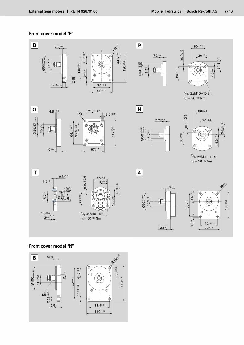
Front cover model “F”
72±0.2
100
± 0.
2 34.5
±0.1
9±
0.11
44.5
±1.5
120
±1.5
90±1.5
12.5−0.4
15,7
±1
7.2± 0.1
Ø18
Ø80
−0.
060
−0.
106
R9
±5 B
112+
1.5
− 1
87+1.5−1
Ø36
.47 −
0.05
15
.7±1
32.5
±0.1
71.4±0.2
8.5±0.11
96.1
±0.2
4.8± 0.1
19± 0.1
R8
O
Ø52
− 0.0
30− 0
.076
36− 0
.5
Ø47
.9−0
.1
34.3
±1.5
14.3
±0.1
min
. 10.
6 60±0.2
7.2±0.1
15.7
±1
10.3+0.3
1.8+0.2
3+0.2
60±0
.2
30±0.1
= 50+10 Nm4xM10 −10.9
T
Ø50
−0.
020
−0.
064
7.2± 0.1
15.7
±1
60±
0.2
14.3
±0.1 34
.3±1
.5
60±0.2
30±0.1
min
. 10.
6
= 50+10 Nm2xM10−10.9
P
= 50+10 Nm2xM10−10.9
Ø50
− 0.0
20− 0
.064
34.3
±1.
5
60±
0.2
60±0.2
30±0.1
min
. 10.
6
14.3
±0.
1
15.7
±1
7.2± 0.1
N
12.5+1
8−0.2
Ø80
− 0.0
60− 0
.106
15.7
±1
120
±1.5
100
±0.2
9.5
±0.2
90±1.5
72±0.2
34.5
±0.1
R9±5
A
Front cover model “N”
B
153±
1.5
55±
1.5
88.4±0.2
110±1.5
132±
0.2 44
.2±
0.1
11±
0.13
5
R 10±
0.59+0.2
2
1:5
Ø22
+0.
5
18.7
5±1
Ø10
0 –0.
054
12.5
8/40 Bosch Rexroth AG Mobile Hydraulics External gear motors RE 14 026/01.05
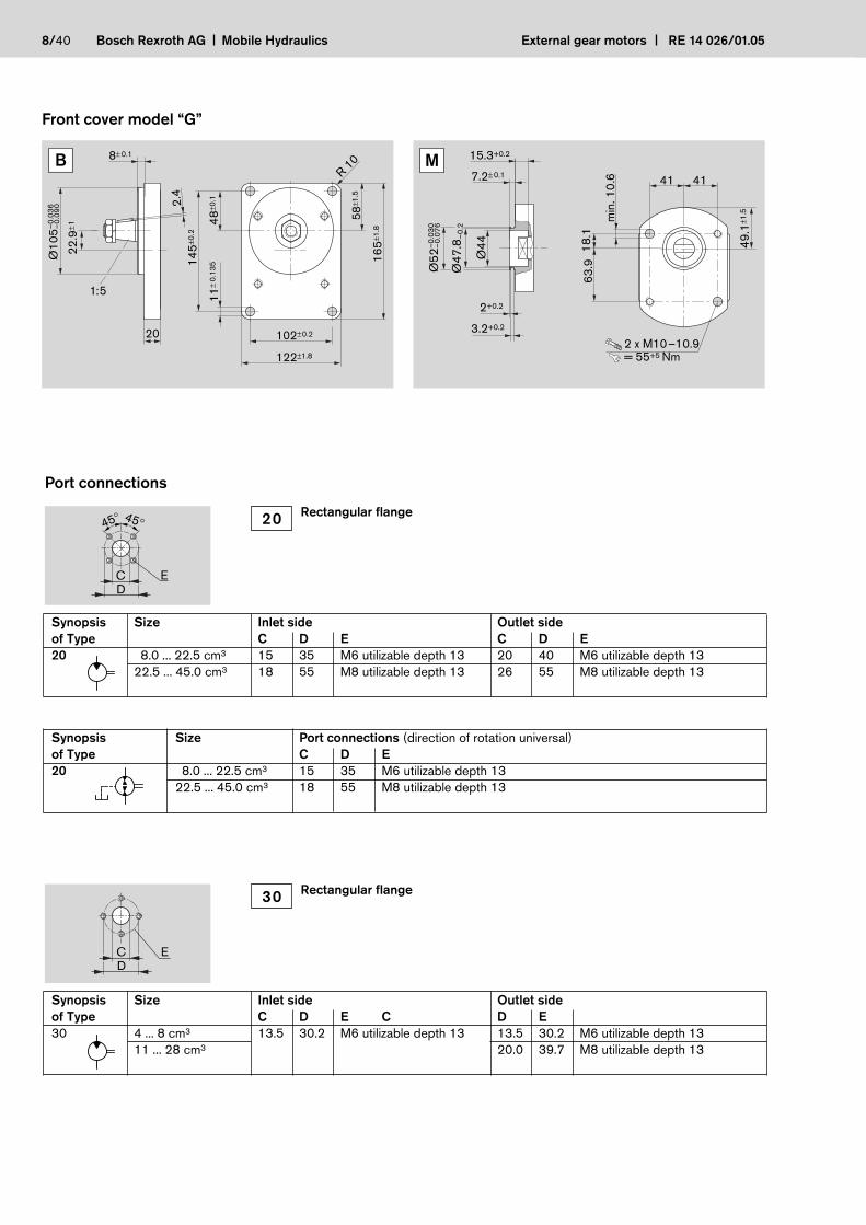
Front cover model “G”
Port connections
Synopsis Size Inlet side Outlet side
of Type C D E C D E
30 4 ... 8 cm3 13.5 30.2 M6 utilizable depth 13 13.5 30.2 M6 utilizable depth 13
11 ... 28 cm3 20.0 39.7 M8 utilizable depth 13
ECD
E
45°45°
CD
Synopsis Size Inlet side Outlet side
of Type C D E C D E
20 8.0 ... 22.5 cm3 15 35 M6 utilizable depth 13 20 40 M6 utilizable depth 13
22.5 ... 45.0 cm3 18 55 M8 utilizable depth 13 26 55 M8 utilizable depth 13
20Rectangular flange
30Rectangular flange
Synopsis Size Port connections (direction of rotation universal)
of Type C D E
20 8.0 ... 22.5 cm3 15 35 M6 utilizable depth 13
22.5 ... 45.0 cm3 18 55 M8 utilizable depth 13
B
145±
0.2
48±0
.1
102±0.2
122±1.8
165±
1.8
58±1
.5
11±
0.13
5
R 10
20
2.4
22.9
±1–0
.036
Ø10
5 –0.
090
8± 0.1
1:5
M
2 x M10–10.9= 55+5 Nm
2+0.2
3.2+0.2
Ø44
Ø47
.8–
0.2
–0.0
30Ø
52–
0.07
6
15.3+0.2
7.2± 0.1
49.1
±1.5
63.9
18.1
min
. 10.
6 4141

External gear motors RE 14 026/01.05 Mobile Hydraulics Bosch Rexroth AG 9/40
External gear motors with integrated valves, sensors
PT
return port pressure < 3 bar (10 bar at starting)
Gear motor with integrated, pilot-operated proportional pres-
sure relief valve and rotary shaft seal relieved of load thanks to
the three-chamber design.
The use of gear motors without this relief of the rotary shaft
seal is not recommended due to the loads from the oil return
line, particularly when the oil is cold. The basis of this drive unit
is a motor model “F”. The pilot proportional pressure relief valve
is integrated in the rear end cover. This unit has the following
advantages:
– No pipework necessary for the functioning of the prop. pres-
sure relief valve
– Integrated pressure relief
– Fail-safe function in the event of power loss
– Drag speed virtually zero
– Motor speed prop. controllable
– Unaffected by pressure loads from the outlet
Additional information see:
Hydrostatic fan drives 1 987 761 700
http://www.boschrexroth.com/brm
External gear motors with pressure relief valve
External gear motors with integrated speed sensor
The DSM1-10 Hall-effect speed sensor was specially
developed for tough use in mobile work machines. The sensor
detects the speed signal of ferromagnetic gear wheels. In this
process, as an active sensor, it supplies a signal with constant
amplitude independent of the rotational speed.
Due to its compact, sturdy design, the gear motor with integra-
ted sensor is suitable for the applications such as
– In fan drives for buses, trucks and construction machinery
from 7 to 20 kW
– As a vibration drive for road rollers and road construction
machinery
For additional information see: Speed Sensor DSM RE 95 132
http://www.boschrexroth.com/brm
p1
Pages 31, 32
Page 23
Page 34

10/40 Bosch Rexroth AG Mobile Hydraulics External gear motors RE 14 026/01.05
The design calculations for motors are
based on the following parameters:
V [cm3/rev] Displacement
Q [l/min] Inlet flow rate
p [bar] Pressure (p1, pA)
M [Nm] Output torque
n [rev/min] Output speed
P [kW] Output power
It is also necessary to allow for different
efficiencies such as:
ηv Volumetric efficiency
ηhm Mechanical-hydraulic efficiency
ηt Total efficiency
The following formulas describe the
various relationships. They include
correction factors for adapting the para-
meters to the usual units encountered
in practice.
Note: Diagrams providing approximate
selection data can be found on sub-
sequent pages. These graphs contain
the levels of efficiency in each case.
p1
pA
PMn
Q
p
[%]Q ηv n∆p ηhm M∆p · Q ηt P
Q =V · n
· 10–1ηv
M ∆p = · 104
1.59 · V · ηhm
Q · ∆p · ηtP = · 104
6
V [cm3/rev] Q [l/min] ∆p [bar] Note: η [%]
n [rev/min] P [kW] M [Nm]
MV = 1.59 · · 104
∆p · ηhm
Q · ηvV = · 10n
M = 1.59 · V · ∆p · ηhm ·10–4
Q · ηvn = · 10V
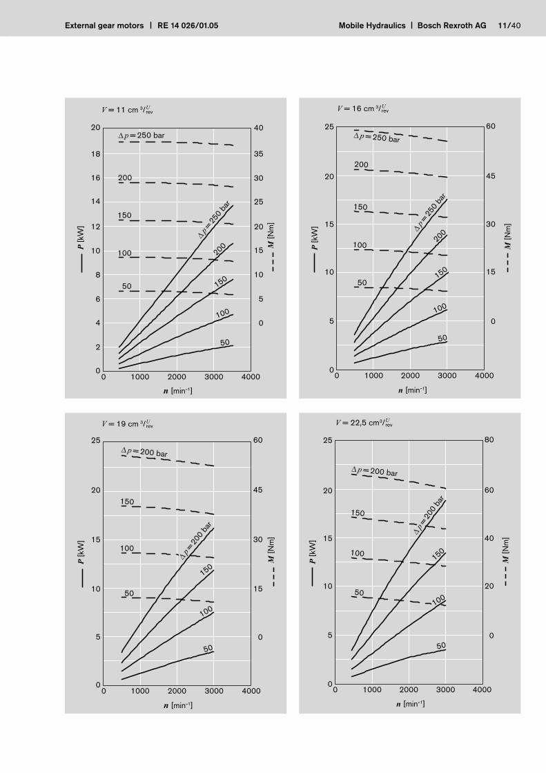
Design calculations for motors
Diagrams Model “F”
2000 3000 400010000
10
0
20
30
40
70
80
60
50
p = 250 barp = 20 bar1) = 200 bar
n [min-1]
Q [l
/min
]
8
1 )
Q =
22,
5 cm
1916
14
11
3
Q = f ( n,V ) incl. ηv
P = f (n, p) incl. ηt
M = f (n, p) incl. ηhm
υ = 35 mm2/s, T = 50 °C
V = 8 cm3/
n [min-1]
3000 4000200010000
10
12
8
6
4
2
0
24
30
18
12
6
0
P [k
W]
M [N
m]
Urev
p = 250 bar
200
150
100
50
p=25
0 ba
r
200
150
100
50
External gear motors RE 14 026/01.05 Mobile Hydraulics Bosch Rexroth AG 11/40
V = 16 cm 3/
3000200010000
20
15
10
5
0
45
25 60
30
15
0
Urev
4000
p = 250 bar
200
150
100
50
p=25
0 ba
r
200
150
100
50
n [min-1]
P [k
W]
M [N
m]
20
15
10
5
0
45
25 60
15
0
30
V = 19 cm 3/
0 3000 400020001000
p=20
0 ba
r
150
100
50
p = 200 bar
150
100
50
Urev
n [min-1]
P [k
W]
M [N
m]
18
20
14
16
12
10
8
6
4
2
0
35
40
25
15
0
5
10
20
30
V = 11 cm 3/
n [min-1]
0 3000 400020001000
p=25
0 ba
r
200
150
100
50
p = 250 bar
200
150
100
50
P [k
W]
M [N
m]
Urev
V = 22,5 cm3/
3000 4000200010000
20
15
10
5
0
60
25 80
40
20
0
Urev
p = 200 bar
150
100
50
p=20
0 ba
r
150
100
50
n [min-1]
P [k
W]
M [N
m]
12/40 Bosch Rexroth AG Mobile Hydraulics External gear motors RE 14 026/01.05
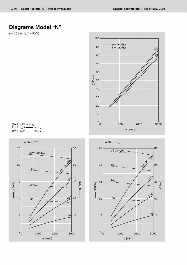
2000 3000100000
20
10
30
50
70
90
40
100
80
60
2825
n [min-1]
Q [l
/min
]
p = 200 barp = 20 bar
V = 25 cm 3/
2000 300010000
25
20
15
5
0
80
60
40
0
10 20
Urev
p = 200 bar
150
100
50
p=20
0 ba
r
150
100
50
n [min-1]
P [k
W]
M [N
m]
3000
20
10
15
5
0
40
60
25 80
20
0
V = 28 cm 3/
0 20001000
p=200 ba
r
150
100
50
p = 200 bar
150
100
50
Urev
n [min-1]
P [k
W]
M [N
m]
Diagrams Model “N”
Q = f ( n,V ) incl. ηv
P = f (n, p) incl. ηt
M = f (n, p) incl. ηhm
υ = 35 mm2/s, T = 50 °C

External gear motors RE 14 026/01.05 Mobile Hydraulics Bosch Rexroth AG 13/40
2000 3000100000
20
40
120
140
100
80
60
p = 200 barp = 20 bar
3832
28
22,5Q
= 4
5 cm
3 /U rev
n [min-1]
Q [l
/min
]
V = 22,5 cm3/
2000 300010000
20
15
10
5
0
60
25 80
40
20
0
Urev
p = 200 bar
150
100
50
p=20
0 ba
r
150
100
50
n [min-1]
P [k
W]
M [N
m]
3000
25
15
20
10
5
0
60
80
30 100
40
20
0
V = 28 cm 3/
0 20001000
p=200 ba
r
150
100
50
p = 200 bar
150
100
50
Urev
n [min-1]
P [k
W]
M [N
m]
Diagrams Model “G” υ = 35 mm2/s, T = 50 °C
Q = f ( n,V ) incl. ηv
P = f (n, p) incl. ηt
M = f (n, p) incl. ηhm
V = 32 cm3/
200010000
25
20
15
10
5
0
80
30 100
60
40
20
0
Urev
3000
p = 200 bar
150
100
50
p=20
0 ba
r
150
100
50
n [min-1]
P [k
W]
M [N
m]

14/40 Bosch Rexroth AG Mobile Hydraulics External gear motors RE 14 026/01.05
45
35
40
25
30
20
15
10
5
0
105
50 120
90
75
60
45
0
30
15
V = 38 cm 3/
0 2000 30001000
p = 200 bar
150
100
50
p = 200 bar
150
100
50
Urev
n [min-1]
P [k
W]
M [N
m]
V = 45 cm3/
2000 300010000
25
30
35
40
45
20
15
40
60
80
100
120
50 140
20
0
10
5
0
Urev
p = 200 bar
150
100
50
p = 200 bar
150
100
50
n [min-1]
P [k
W]
M [N
m]
Specifications*) During the application of con-
trol systems or devices with
critical counter-reaction, such
as steering and brake valves,
the type of filtration selected
must be adapted to the sensi-
tivity of these devices/systems.
Safety requirements pertaining
to the whole systems are to be
observed.
In the case of applications with
frequent load cycles please con-
sult us.
General
Construction external gear motor
Mounting Flange or through-bolting with spigot
Port connections screw, flange
Direction of rotation One direction of rotation or reversible(looking on shaft)
Mounting position any
Load on shaft radial and axial forces after consulting
Ambient temperature range –30 °C...+80 °C
Fluids mineral oil-based hydraulic fluids to DIN/ISO,other fluids upon request
Viscosity 12…800 mm2/s permitted range20…100 mm2/s recommended range12…2,000 mm2/s permitted for starting
Fluid temperature range –30 °C…+80 °C–20 °C…+110 °C with FPM seals
Filter *) contamination at least class 19/16 according toISO 4406 to be obtained with filter b20 = 75. For higher lifespan demands we recommend a correspondingly higher filter class.

p2
t [s]
p [b
ar]
drive shaft
for one direction of rotation
reversible
clockwise rotationcounter-clockwise rotation p1
Model F
Displacement cm3/rev 5.5 1) 8 11 14 16 19 22.5
max. continuous pressure p1 bar 250 180
max. starting pressure p2 280 210
min. rotational speed min–1 500
max. rotational speed p1 4,000 3,500 3,000
Motor outlet pressure pA barLeakage-oil line pressure pL
Model N
Displacement cm3/rev 25 28
max. continuous pressure p1 bar 210 200
max. starting pressure p2 240 230
min. rotational speed min–1 500
max. rotational speed p1 3,000
Motor outlet pressure pA barLeakage-oil line pressure pL
Model G
Displacement cm3/rev 22.5 28 32 38 45
max. continuous pressure p1 bar 180
max. starting pressure p2 210
min. rotational speed min–1 500
max. rotational speed p1 3,000 2,800 2,600
Motor outlet pressure pA barLeakage-oil line pressure pL
1) On request *) Short-term when starting 10 bar
p1p1
pA 3 bar*) pA p1
pL < 3 bar*)
p1
pA 3 bar*)
p1
pA 3 bar*)
p1 max. continuous pressure
p2 starting pressure (depending on the ap-
plication, this must be taken into consid-
eration when setting the pressure of the
hydraulic system’s pressure-relief valve).
External gear motors RE 14 026/01.05 Mobile Hydraulics Bosch Rexroth AG 15/40
16/40 Bosch Rexroth AG Mobile Hydraulics External gear motors RE 14 026/01.05
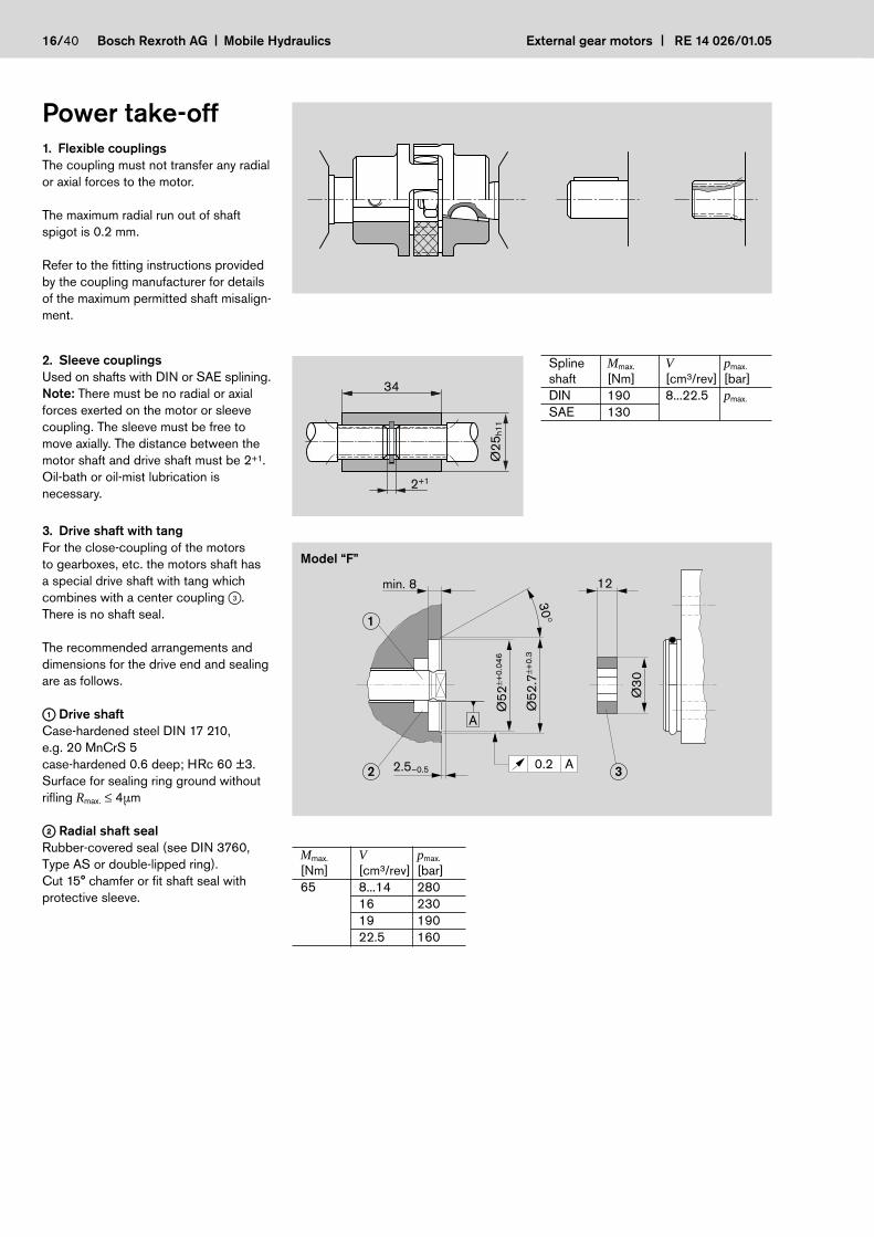
Power take-off
1. Flexible couplings
The coupling must not transfer any radial
or axial forces to the motor.
The maximum radial run out of shaft
spigot is 0.2 mm.
Refer to the fitting instructions provided
by the coupling manufacturer for details
of the maximum permitted shaft misalign-
ment.
2. Sleeve couplings
Used on shafts with DIN or SAE splining.
Note: There must be no radial or axial
forces exerted on the motor or sleeve
coupling. The sleeve must be free to
move axially. The distance between the
motor shaft and drive shaft must be 2+1.
Oil-bath or oil-mist lubrication is
necessary.
3. Drive shaft with tang
For the close-coupling of the motors
to gearboxes, etc. the motors shaft has
a special drive shaft with tang which
combines with a center coupling 3.
There is no shaft seal.
The recommended arrangements and
dimensions for the drive end and sealing
are as follows.
11 Drive shaft
Case-hardened steel DIN 17 210,
e.g. 20 MnCrS 5
case-hardened 0.6 deep; HRc 60 ±3.
Surface for sealing ring ground without
rifling Rmax. ≤ 4µm
22 Radial shaft seal
Rubber-covered seal (see DIN 3760,
Type AS or double-lipped ring).
Cut 15° chamfer or fit shaft seal with
protective sleeve.
2+1
34
Ø25
h11
2.5–0.5
30°
12
Ø30
min. 8
Ø52
±+0.
046
Ø52
.7±+
0.3
1
2 30.2 A
A
Spline Mmax. V pmax.
shaft [Nm] [cm3/rev] [bar]
DIN 190 8...22.5 pmax.
SAE 130
Mmax. V pmax.
[Nm] [cm3/rev] [bar]
65 8...14 280
16 230
19 190
22.5 160
Model “F”

4. Outboard bearing Model “F”Outboard bearings eliminate possible problems when the motors are driven by V-belts or gearwheels. The diagrams below show the maximum overhung and thrust loads that can be tolerated, referring to a bearing life of LH = 1,000 hours.
External gear motors RE 14 026/01.05 Mobile Hydraulics Bosch Rexroth AG 17/40
a
Fr
Fa
10 20 30
n = 1500 [min –1]
n = 2000n = 3000n = 4000
40 50 60
1400
a [mm]
Fr [N
]
1200
1000
800
600
400
Mmax. V pmax.
[Nm] [cm3/rev] [bar]65 16 230
19 19022.5 160
Fr is reduced by 0.7 Fa when axialloading Fa is applied.
ConnectorsGear motor flange, 3-bolt, 90° angle, for square flange 30 see page 8
M6-8.8 = 10+3 NmM8-8.8 = 25+5 NmLK
LA
Ø D3
Ø D1 S1
L3
L4
L5
L1L2
Ø D
B
LK D1 D3 L1 L2 L3 L4 L5 LA S1 DB Screws O-ring Weight Ordering-No. p3 pieces NBR *) [kg] [bar]
30 12L 10 37 30.0 10 37.5 46 38 22 6.4 M6x22 16x2.5 0.13 1 515 702 146 25030 15L 12 37 30.0 10 37.5 47 38 27 6.4 M6x22 16x2.5 0.14 1 515 702 147 25030 18L 15 37 30.0 10 37.5 47 38 32 6.4 M6x22 16x2.5 0.17 1 515 702 148 16040 22L 19 43 35.5 14 41.0 53 48 36 8.4 M8x30 24x2.5 0.29 1 515 702 149 16040 28L 24 43 35.5 14 41.0 53 48 41 8.4 M8x30 24x2.5 0.40 1 515 702 150 160
Complete screw connection with O-ring, metric screw set, nut/mother and sleeve fitting *) NBR = Perbunan®

18/40 Bosch Rexroth AG Mobile Hydraulics External gear motors RE 14 026/01.05
Connectors (continuation)
Gear motor flange, straight, for square flange 20 see page 8
LAL4 S1
L2
L1
Ø D
3
Ø D
1
Ø D
1
Ø DB LK
LA
M6-8.8 = 10+3 Nm
LK D1 D3 L1 L2 L4 LA S1 DB Screws O-ring Weight Ordering-No. p4 pieces NBR *) [kg] [bar]
35 10L 8 30 23.0 39.0 40 19 6.4 M6x22 20x2.5 0.09 1 515 702 064 315
35 12L 10 30 23.0 39.0 40 22 6.4 M6x22 20x2.5 0.10 1 515 702 065 315
35 15L 12 30 23.0 38.0 40 27 6.4 M6x22 20x2.5 0.10 1 515 702 066 250
40 15L 12 35 28.0 43.0 42 27 6.4 M6x22 24x2.5 0.12 1 515 702 067 100
40 18L 15 35 27.5 44.0 42 32 6.4 M6x22 24x2.5 0.13 1 515 702 068 100
40 22L 19 35 27.5 44.5 42 36 6.4 M6x22 24x2.5 0.12 1 515 702 069 100
40 28L 24 42 27.5 34.5 42 41 6.4 M6x22 24x2.5 0.15 1 515 702 008 100
Complete screw connection with O-ring, metric screw set, nut/mother and sleeve fitting *) NBR = Perbunan®
Gear motor flange, 90° angle, for square flange 20 see page 8
M6-8.8 = 10+3 NmM8-8.8 = 25+5 NmLA
S1
L2L1
L3
L4
L5
Ø D3
Ø D1
Ø D1
LK
Ø D
BLA
LK D1 D3 L1 L2 L3 L4 L5 LA S1 DB Screws O-ring Weight Ordering-No. p2 pcs. 2 pcs. NBR *) [kg] [bar]
35 10L 8 38 31.0 16.5 26.5 47.0 40 19 6.4 M6 x 22 M6 x 35 20 x 2.5 0.16 1 515 702 070 315
35 12L 10 38 31.0 16.5 26.5 47.0 40 22 6.4 M6 x 22 M6 x 35 20 x 2.5 0.16 1 515 702 071 315
35 15L 12 38 31.0 16.5 26.5 46.0 40 27 6.4 M6 x 22 M6 x 35 20 x 2.5 0.15 1 515 702 072 250
35 16S 12 38 29.5 20.0 31.0 48.0 40 30 6.4 M6 x 22 M6 x 40 20 x 2.5 0.18 1 515 702 002 315
35 18L 15 38 29.5 20.0 31.0 47.0 40 32 6.4 M6 x 22 M6 x 40 20 x 2.5 0.18 1 545 702 006 250
35 20S 16 45 34.5 25.0 38.0 56.0 40 36 6.4 M6 x 22 M6 x 45 20 x 2.5 0.24 1 515 702 017 315
40 15L 12 38 31.0 22.5 36.5 46.0 42 27 6.4 M6 x 22 M6 x 22 24 x 2.5 0.15 1 515 702 076 100
40 18L 15 38 30.5 22.5 36.5 47.0 42 32 6.4 M6 x 22 M6 x 22 24 x 2.5 0.17 1 515 702 074 100
40 20S 16 40 29.5 22.5 35.5 50.0 42 36 6.4 M6 x 22 M6 x 45 24 x 2.5 0.20 1 515 702 011 250
40 22L 19 38 30.5 22.5 36.5 47.5 42 36 6.4 M6 x 22 M6 x 22 24 x 2.5 0.17 1 515 702 075 100
40 28L 22 40 32.5 28.0 43.0 49.0 42 41 6.4 M6 x 20 M6 x 50 24 x 2.5 0.24 1 515 702 010 100
40 35L 31 41 30.5 34.0 55.0 52.0 42 50 6.4 M6 x 22 M6 x 60 24 x 2.5 0.33 1 515 702 018 100
55 20S 17 45 34.5 24.0 40.0 56.0 58 36 8.4 M8 x 25 M8 x 50 33 x 2.5 0.44 1 515 702 004 250
55 30S 26 49 35.5 32.0 50.0 62.0 58 50 8.4 M8 x 25 M8 x 50 33 x 2.5 0.50 1 515 702 006 250
55 35L 31 49 38.5 32.0 51.5 62.0 58 50 8.4 M8 x 25 M8 x 60 33 x 2.5 0.47 1 515 702 005 100
55 42L 38 49 38.0 40.0 64.5 61.0 58 60 8.4 M8 x 25 M8 x 70 33 x 2.5 0.60 1 515 702 019 100
Complete screw connection with O-ring. metric screw set. nut/mother and sleeve fitting *) NBR = Perbunan®

External gear motors RE 14 026/01.05 Mobile Hydraulics Bosch Rexroth AG 19/40
Dimensions in mmF-Motor
45° 45°
Ø1
7–
0.1
1
3–
0.0
25
84
–0
.2
17
7.8± 0.35
5°4
2'3
8"
±1'
3 x5 DIN 6888
DIN EN ISO 8673-M12x1.5-m-06
DIN 128-A12-FSt
= 50+10 Nm
As shown in drawing
Inlet and outlet port changed
12
0±
1.5
72±0.2
90±1.5
10
0±
0.2
34
.5±
0.1
9±
0.1
1
44
.5±1
.5
R 9±0.5
15
35± 0.15
20
40± 0.15
A± 0.4
Ø18
12.5–0.4
15
.7±1
–0
.06
0Ø
80
–0
.10
638± 0.6
7.2± 0.1
1:5
B±1.2
= 10+3 NmM6
= 10+3 NmM6
10
0+
1.5
–1
45° 45°
1.8
A 5
11
24
0 0
01
Ordering code
AZMF – 1x – � � � � C B 20 M B
AZMF – 10 – � � � � C B 20 K B*
AZMF – 10 – � � � � C B 20 M B – S0012 **
Displace- Ordering-No. Max. Min. Max. kg Dimensionment operating rotation rotationn N pressure speed speed [mm][cm3/rev] L R [bar] [min–1] [min–1] A B
8 0 511 425 300 0 511 425 001 210 500 4,000 2.9 43.2 91.1
11 0 511 525 300 0 511 525 001 210 500 3,500 3.0 47.0 96.3
14 0 511 525 304 – 210 500 3,000 3.2 47.5 101.3
16 – 0 511 625 005 210 500 3,000 3.4 47.5 104.7
19 0 511 625 308 0 511 625 003 180 500 3,000 3.6 47.5 109.7
19 – 0 511 625 009 * 180 500 3,000 3.6 47.5 109.7
22.5 0 511 725 304 ** 0 511 725 005 ** 210 500 3,000 3.9 61.1 125.3
Dimensions in mmF-Motor
45° 45°
12
0±
1.5
72±0.2
90±1.5
15
35± 0.15
A± 0.4
12.5–0.4
2–0.5
Ø1
823.5–0.8
As shown in drawing
10
0±
0.2
34
.5±
0.1
9±
0.1
1
44
.5±1
.5
15
.7±1–
0.0
60
Ø8
0–
0.1
06
7.2± 0.1
B± 0.7
= 10+3 NmM6
R 9±0.5
10
0+
1.5
–1
min. 14.8
usable shaft length
DIN 5482 B 17 x 14tooth thickness sw = 3.200–0.030
Ø1
6.5
–0
.27
84
–0
.2
45° 45°
Inlet and outlet port changed
20
40± 0.15
= 10+3 NmM6
A 5
11
241
001
20/40 Bosch Rexroth AG Mobile Hydraulics External gear motors RE 14 026/01.05
Ordering code
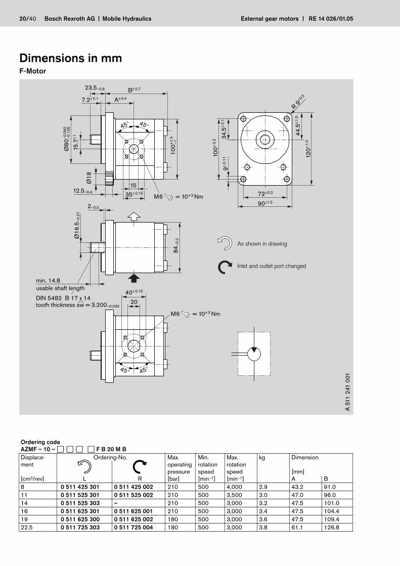
AZMF – 10 – � � � � F B 20 M B
Displace- Ordering-No. Max. Min. Max. kg Dimensionment operating rotation rotation n N pressure speed speed [mm][cm3/rev] L R [bar] [min–1] [min–1] A B
8 0 511 425 301 0 511 425 002 210 500 4,000 2.9 43.2 91.0
11 0 511 525 301 0 511 525 002 210 500 3,500 3.0 47.0 96.0
14 0 511 525 303 – 210 500 3,000 3.2 47.5 101.0
16 0 511 625 301 0 511 625 001 210 500 3,000 3.4 47.5 104.4
19 0 511 625 300 0 511 625 002 180 500 3,000 3.6 47.5 109.4
22.5 0 511 725 303 0 511 725 004 180 500 3,000 3.8 61.1 126.8

External gear motors RE 14 026/01.05 Mobile Hydraulics Bosch Rexroth AG 21/40
Dimensions in mmF-Motor
0.5± 0.5
As shown in drawing
= 10+3 NmM61
00
+1
.5–
1
usable shaft length
DIN 5482 B 17 x 14tooth thickness sw = 3.200–0.030
Ø1
6.5
–0
.27
84
–0
.2
A± 0.4
15
.7±1
4.8± 0.1
19± 0.1
96
.1±
0.2 3
2.5
±0
.1
40
.5±1
.5
B± 0.7 71.4± 0.2
8.5± 0.11R 9
30.2± 0.15
13.5
22± 0.4
11
3+
1.5
–1
Ø3
6.4
7–
0.0
5
88+1.5–1
min. 14.8
Inlet and outlet port changed
C
D
E
A 5
11
241
021
Ordering code
AZMF – 10 – � � � � F O 30 M B
Displace- Ordering-No. Max. Min. Max. kg Dimensionment operating rotation rotationn N pressure speed speed [mm][cm3/rev] L R [bar] [min–1] [min–1] A B C D E
8 – 0 511 425 003 210 500 4,000 2.9 44.9 90.7 13.5 30.2 M6 = 10+3
19 0 511 625 303 – 180 500 3,000 3.7 49.0 109.1 20.0 39.7 M8 = 25+5
22.5 – 0 511 725 305 180 500 3,000 3.9 56.6 114.5 20.0 39.7 M8 = 25+5

Dimensions in mmF-Motor
As shown in drawing
12
0±
1.5
72±0.2
90±1.5
10
0±
0.2 3
4.5
±0
.19
.5±
0.2
2
44
.5±1
.5
R 9±0.5
A± 0.4
B±0.7
10
0+
1.5
–1
45+0.5–1
8–0.2
45° 45°
12.5+1
15
15
.7±1–
0.0
60
Ø8
0–
0.1
06
1:5
= 10+3 NmM635± 0.15
4–
0.0
3
84
–0
.2
19.2
9.5± 0.7
5°4
2'3
8"
±1'
4x6.5 DIN 6888
DIN EN ISO 8674-M12x1.5-m-06
DIN 128-A12-FSt
= 70+15 Nm
–0
.06
5Ø
20
–0
.11
7
45° 45°
2
Inlet and outlet port changed
20
40± 0.15
= 10+3 NmM6
A 5
11
24
3 0
21
22/40 Bosch Rexroth AG Mobile Hydraulics External gear motors RE 14 026/01.05
Ordering code
AZMF – 10 – � � � � S A 20 M B
AZMF – 10 – � � � � S A 20 M B – S0012
Displace- Ordering-No. Max. Min. Max. kg Dimensionment operating rotation rotationn N pressure speed speed [mm][cm3/rev] L R [bar] [min–1] [min–1] A B
8 0 511 445 300 0 511 445 001 250 500 4,000 3.5 74.7 120.6
11 0 511 545 300 0 511 545 001 250 500 3,500 3.6 78.5 125.6
14 0 511 545 301 – 250 500 3,000 3.7 79.0 130.6
16 0 511 645 300 0 511 645 001 250 500 3,000 3.8 79.0 134.0
16 – 0 511 645 003 230 500 3,000 3.8 93.0 134.0
19 0 511 645 302 – 190 500 3,000 4.2 79.0 139.0
22.5 0 511 745 300* 0 511 745 001* 160 500 2,500 4.8 92.6 156.4

External gear motors RE 14 026/01.05 Mobile Hydraulics Bosch Rexroth AG 23/40
Dimensions in mmF-Motor
9.5± 0.7
4x6.5 DIN 6888
DIN EN ISO 8674-M12x1.5-m-06
DIN 128-A14-FSt
= 70+10 Nm
B±0.7
max. 11
X
10
0+
1.5
–1
Ø2
4
5°4
2'3
8"
±1'–
0.0
65
Ø2
0–
0.1
17
4–
0.0
3
19.2
86
–0
.8
Inlet M 18 x 1.5useable depth min. 12
"X"27±1
= 50+10 Nm
12
0±
1.5
72±0.2
90±1.5
10
0±
0.2 3
4.5
±0
.19
.5±
0.2
44
.5±1
.5
R 9±0.5
= 10+3 NmM6
As shown in drawing
Other position of the drive shaft
A± 0.4
45+0.5–1
8–0.2
12.5+120
–0
.06
0Ø
80
–0
.10
6
1:5
40± 0.15
15
.7±1
45° 45°2
A 5
11
24
3 7
09
Ordering code
AZMF – 10 – � � � � S A 20 M D XXXXX – S0076
Displace- Ordering-No. Max. Min. Max. kg Dimensionment operating rotation rotationn N pressure speed speed [mm][cm3/rev] L R [bar] [min–1] [min–1] A B
8 0 511 445 301 0 511 445 003 200 500 4,000 3.6 74.7 133.1
11 0 511 545 302 0 511 545 003 150 500 3,500 3.8 79.1 138.1

Dimensions in mmF-Motor
incl.
incl. 1 510 240 000
resp. 1 510 240 009
1 900 210 145
45° 45°
As shown in drawing
34
.3±1
.5
14
.3±0
.1
60
±0.2
60±0.2
min
. 1
0.6
4 x M10–10.9
30±0.1
= 50+10 Nm
B± 0.5 4± 0.8
A± 0.4
Ø2
1
10
0+
1.5
–1
7.2± 0.1
45° 45°
Ø1
7.8
–0
.07
–0
.02
58
–0
.08
3
15
.7±1
15
35± 0.15
2.7+0.5
6.5+0.2
= 10+3 NmM6
1.8+0.2
3+0.2
Ø3
6–
0.5
Ø4
7.9
–0
.1
–0
.03
0Ø
52
–0
.07
6
84
–0
.2
Motor without radial shaft seal
10.3+0.3
Inlet and outlet port changed
20
40± 0.15
= 10+3 NmM6
A 5
11
23
2 0
01
Ordering code
AZMF – 10 – � � � � N T 20 M B
Displace- Ordering-No. Max. Min. Max. kg Dimensionment operating rotation rotationn N pressure speed speed [mm][cm3/rev] L R [bar] [min–1] [min–1] A B
8 0 511 415 300 0 511 415 001 250 500 4,000 2.5 40.7 80.3
11 0 511 515 300 0 511 515 001 250 500 3,500 2.6 44.5 85.3
16 0 511 615 301 0 511 615 002 230 500 3,000 3.0 45.0 93.7
19 0 511 615 300 0 511 615 001 190 500 3,000 3.2 45.0 98.7
22.5 0 511 715 300 0 511 715 001 160 500 3,000 3.4 52.6 104.1
24/40 Bosch Rexroth AG Mobile Hydraulics External gear motors RE 14 026/01.05

External gear motors RE 14 026/01.05 Mobile Hydraulics Bosch Rexroth AG 25/40
Dimensions in mmF-Motor
Ø1
7–
0.0
27
5°4
2'3
8"
±1'
45° 45°
17
3x5 DIN 6888
DIN EN ISO 8673-M12x1.5-m-06
DIN 128-A12-FSt
= 50+10 Nm
Drain oil line connection M12x1.5 useable depth min.13
84
–0
.2
= 15+5 Nm
A± 0.4
31
.4±1
Ø2
2
38± 0.6
7.2± 0.1
B±0.7
L±0.4
= 10+3 NmM6
= 10+3 NmM6
10
0+
1.5
–1
Ø18
12.5–0.4
15
.7±1
–0
.06
0Ø
80
–0
.10
6
1:5
15
35± 0.15
15
35± 0.15
1.8
45°45°
12
0±
1.5
72±0.2
90±1.5
10
0±
0.2
9±
0.1
1
44
.5±1
.5
R 9±0.5
34
.5±
0.1
7.8± 0.35
A 5
11
24
0 6
10
Ordering code
AZMF – 10 – � � � U C B 20 M L
AZMF – 10 – � � � U C B 20 K L*
Displace- Ordering-No. Max. Min. Max. kg Dimensionment operating- rotation rotation
pressure speed speed [mm][cm3/rev] Universal [bar] [min–1] [min–1] A B L
8 0 511 425 601 210 500 4,000 3.4 43.2 90.7 85.8
11 0 511 525 604 210 500 3,500 4.2 47.0 95.9 90.8
16 0 511 625 602 210 500 3,000 3.9 47.5 104.3 99.2
22.5 0 511 725 601 * 180 500 3,000 3.9 55.1 114.6 109.6
Dimensions in mmF-Motor
Drain oil line connection M12x1.5 useable depth min.13
= 15+5 Nm
min. 14.8
usable shaft length
DIN 5482 B 17 x 14tooth thickness sw = 3.200–0.030
45° 45°
2± 0.5
Ø1
6.5
–0
.27
84
–0
.2
12
0±
1.5
72±0.2
90±1.5
10
0±
0.2
34
.5±
0.1
9±
0.1
1
44
.5±1
.5
R 9±0.5
31
.4±1
Ø2
2
= 10+3 NmM6
= 10+3 NmM6
10
0+
1.5
–1
A± 0.47.2± 0.1
B±0.7
L±0.4
15
.7±1
–0
.06
0Ø
80
–0
.10
6
23.5–0.8
15
35± 0.15
15
35± 0.15
45°45°
12.5–0.4
A 5
11
241
60
7
26/40 Bosch Rexroth AG Mobile Hydraulics External gear motors RE 14 026/01.05
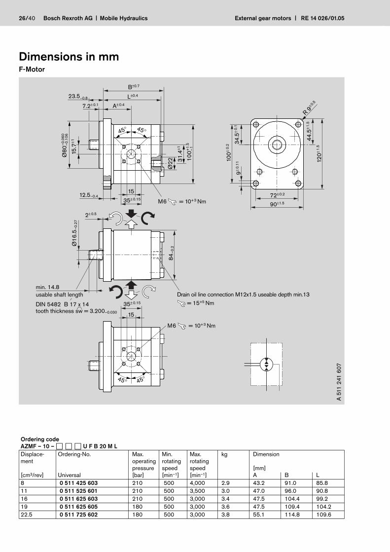
Ordering code
AZMF – 10 – � � � U F B 20 M L
Displace- Ordering-No. Max. Min. Max. kg Dimensionment operating rotating rotating
pressure speed speed [mm][cm3/rev] Universal [bar] [min–1] [min–1] A B L
8 0 511 425 603 210 500 4,000 2.9 43.2 91.0 85.8
11 0 511 525 601 210 500 3,500 3.0 47.0 96.0 90.8
16 0 511 625 603 210 500 3,000 3.4 47.5 104.4 99.2
19 0 511 625 605 180 500 3,000 3.6 47.5 109.4 104.2
22.5 0 511 725 602 180 500 3,000 3.8 55.1 114.8 109.6

External gear motors RE 14 026/01.05 Mobile Hydraulics Bosch Rexroth AG 27/40
Dimensions in mmF-Motor
72±0.2
90±1.5
10
0±
0.2
9.5
±0
.11
A± 0.7
10
0+
1.5
–1
45+0.5–1
8–0.2
= 10+3 NmM6
4–
0.0
3
84
–0
.2
19.2
4x6.5 DIN 6888
DIN EN ISO 8674-M12x1.5-m-06
DIN 128-A12-FSt
= 70+10 Nm
45° 45°
34
.5±
0.1
31
.4±1
Ø2
2
B±0.8
L±0.4
45° 45°
12.5+1
–0
.06
0Ø
80
–0
.10
6
1:5
35± 0.15
15
.7±1
15
= 10+3 NmM6
35± 0.15
15
5°4
2'3
8"
±1'–
0.0
65
Ø2
0–
0.1
17
9.5± 0.7
Drain oil line connection M12x1.5 useable depth min.13
= 15+5 Nm
12
0±
1.5
44
.5±1
.5
R 9±0.5
2
A 5
11
24
3 6
12
Ordering code
AZMF – 10 – � � � U S A 20 M L
Displace- Ordering-No. Max. Min. Max. kg Dimensionment operating rotation rotation
pressure speed speed [mm][cm3/rev] Universal [bar] [min–1] [min–1] A B L
8 0 511 445 601 250 500 4,000 3.5 74.8 120.8 116.9
11 0 511 545 601 250 500 3,500 3.6 78.6 125.8 121.9
16 0 511 645 601 230 500 3,000 4.0 79.1 134.2 130.3
19 0 511 645 603 190 500 3,000 4.2 79.1 139.2 135.3
Dimensions in mmF-Motor
34
.3±1
.5
14
.3±0
.1
60
±0.2
60±0.2
min
. 1
0.6
4 x M10–10.9
30±0.1
= 50+10 Nm
B± 0.5 4± 0.8
A± 0.4
Ø2
1
10
0+
1.5
–1
L± 0.7
7.2± 0.1
45° 45°
Ø1
7.8
–0
.07
15
.7±1
15
35± 0.15
2.7+0.5
6.5+0.2
Drain oil line connection M12x1.5 useable depth min.13
= 15+5 Nm
84
–0
.23
1.4
±1
Ø2
2
Ø3
6–
0.5
Ø4
7.9
–0
.1
10.3+0.3
–0
.03
0Ø
52
–0
.07
6
1.8+0.2
3+0.2
Motor without radial shaft seal
incl. 1 510 240 000
resp. 1 510 240 009
1 900 210 145
45° 45°
incl.
= 10+3 NmM6
–0
.02
58
–0
.08
3
= 10+3 NmM6
35± 0.15
15
A 5
11
23
2 6
24
28/40 Bosch Rexroth AG Mobile Hydraulics External gear motors RE 14 026/01.05
Ordering code
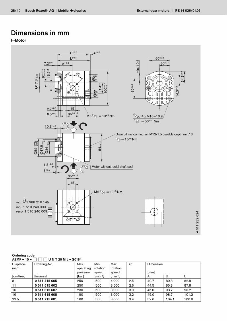
AZMF – 10 – � � � U N T 20 M L – S0164
Displace- Ordering-No. Max. Min. Max. kg Dimensionment operating rotation rotation
pressure speed speed [mm][cm3/rev] Universal [bar] [min–1] [min–1] A B L
8 0 511 415 605 250 500 4,000 2.5 40.7 80.3 82.8
11 0 511 515 602 250 500 3,500 2.6 44.5 85.3 87.8
16 0 511 615 607 230 500 3,000 3.0 45.0 93.7 96.2
19 0 511 615 608 190 500 3,000 3.2 45.0 98.7 101.2
22.5 0 511 715 601 160 500 3,000 3.4 52.6 104.1 106.6

External gear motors RE 14 026/01.05 Mobile Hydraulics Bosch Rexroth AG 29/40
Dimensions in mmF-Motor
3–
0.0
25
A± 0.4
40.2± 0.6
7.2± 0.1
B±0.5 max. 9
L±0.415
.7±1–0
.02
0Ø
50
–0
.06
4
31
.4±1
Ø2
2 10
0+
1.5
–1
= 10+3 NmM6
= 10+3 NmM6
15
35± 0.15
15
35± 0.15
1:5
1.8
45°45°
34
.3±1
.5
14
.3±0
.1
60
±0.2
60±0.2
min
. 1
0.6
2 x M10–10.9
30±0.1
= 50+10 Nm
10.3± 0.35
Ø1
7–
0.0
27
5°4
2'3
8"
±1'
17
Drain oil line connection M12x1.5 useable depth min.13
= 15+5 Nm
84
–0
.2
Ø2
1
45° 45°
3x5 DIN 6888
DIN EN ISO 8673-M12x1.5-m-06
DIN 128-A12-FSt
= 50+10 Nm
A 5
11
23
0 6
11
Ordering code
AZMF – 1X – � � � U C P 20 M L
Displace- Ordering-No. Max. Min. Max. kg Dimensionment operating rotation rotation
pressure speed speed [mm][cm3/rev] Universal [bar] [min–1] [min–1] A B L
8 0 511 415 606 210 500 4,000 2.8 40.7 80.3 83.3
11 0 511 515 601 210 500 3,500 2.8 44.5 85.3 88.3
14 0 511 515 605 210 500 3,000 3.1 45.0 90.3 93.3
16 0 511 615 609 210 500 3,000 3.1 45.0 93.7 96.7

Dimensions in mmF-Motor
34
.3±1
.5
14
.3±0
.1
60
±0.2
60±0.2
30±0.1
min
. 1
0.6
2 x M10–10.9
= 50+10 Nm
Drain oil line connection M12x1.5useable depth min.13
= 10+3 NmM6
= 10+3 NmM6
15
35± 0.15
15
35± 0.15
Ø2
1
A± 0.4
40.2± 0.6
7.2± 0.1
B±0.5 16±1
L±0.4
15
.7±1–0
.02
0Ø
50
–0
.06
4
1:5
1.8
45°45°
= 15+5 Nm
45° 45°
3x5 DIN 6888
DIN EN ISO 8673-M12x1.5-m-06
DIN 128-A12-FSt
= 50+10 Nm
10.3± 0.35
38
.5±
0.5Ø
17
–0
.02
7
5°4
2'3
8"
±1'
17
84
–0
.2
A 5
11
23
0 6
18
30/40 Bosch Rexroth AG Mobile Hydraulics External gear motors RE 14 026/01.05
Ordering code
AZMF – 11 – � � � U C N 20 M B – S0077
Displace- Ordering-No. Max. Min. Max. kg Dimensionment operating rotation rotation
pressure speed speed [mm][cm3/rev] Universal [bar] [min–1] [min–1] A B L
8 0 511 415 607 210 500 4,000 2.9 40.7 80.3 80.3

External gear motors RE 14 026/01.05 Mobile Hydraulics Bosch Rexroth AG 31/40
Dimensions in mmF-Motor
P
As shown in drawing
5°4
2'3
8"
±1'
4–
0.0
3
8–0.2
–0
.06
5Ø
20
–0
.11
7
19.2
4x6.5 DIN 6888
DIN EN ISO 8674-M14x1.5-8-A
DIN 128-A14-FSt
= 70+15 Nm
Drain oil line connection M12x1.5
not contained in delivery
= 15+5 Nm
= 10+3 NmM6
20
40± 0.15
24
14±1
9.5±0.7
45°45°
Position of shaft on anti-clockwise rotation
Position of drain oil port on anti-clockwise rotation
R 9 ±
0.5
12
0±
1.5
72±0.2
90±1.5
10
0±
0.2
9.5
44
.5±1
.5
34
.5±
0.1
= 10+3 NmM6
16
1.6
±4.6
86
.7±4
.3
15
35± 0.15
12.5+1
A±0.4
B±0.7 24.5±2
2
–0
.06
0
15
.7±1
–0
.06
0Ø
80
–0
.10
6
+0.545–1
45° 45°
0°±2
0°
39
.5–
0.5 84
–0
.5
Position of connectors
1:5
A 5
11
24
3 7
26
Ordering code
AZMF – 11 – � � � � S A 20 P GXXXX
AZMF – 12 – � � � � S A 20 P GXXXX*
Displace- Ordering-No. Min. Max. PVR Coil kg Dimensionment rotation rotation nominaln N speed speed current [mm][cm3/rev] L R [min–1] [min–1] [bar] [I] A B
16 – 0 511 645 007 500 3,000 130 1.5 5.0 79.0 137.7
16 – 0 511 645 005 * 500 3,000 170 1.5 5.0 79.0 137.7
16 0 511 645 306 – 500 3,000 170 1.5 5.1 79.0 137.7
16 0 511 645 307 – 500 3,000 210 1.5 5.1 79.0 137.7
16 – 0 511 645 011 * 500 3,000 210 1.5 5.1 79.0 137.7

Dimensions in mmF-Motor
P
As shown in drawing
5°4
2'3
8"
±1'
4–
0.0
3
8–0.2
–0
.06
5Ø
20
–0
.11
7
19.2
4x6.5 DIN 6888
DIN EN ISO 8674-M14x1.5-8-A
DIN 128-A14-FSt
= 70+15 Nm
Drain oil line connection M12x1.5
not contained in delivery
= 15+5 Nm
= 10+3 NmM6
20
40± 0.15
24
14±1
9.5±0.7
45°45°
Position of shaft on anti-clockwise rotation
Position of drain oil port on anti-clockwise rotation
R 9 ±
0.5
12
0±
1.5
72±0.2
90±1.5
10
0±
0.2
9.5
44
.5±
1.5
34
.5±
0.1
= 10+3 NmM6
16
1.6
±4.6
86
.7±4
.3
15
35± 0.15
12.5+1
A±0.4
B±0.7 24.5±2
2
–0
.06
0
15
.7±
1
–0
.06
0Ø
80
–0
.10
6
+0.545–1
45° 45°
0°±2
0°
39
.5–
0.5 84
–0
.5
Position of connectors
1:5
A 5
11
24
0 7
70
32/40 Bosch Rexroth AG Mobile Hydraulics External gear motors RE 14 026/01.05

Dimensions in mmF-Motor
External gear motors RE 14 026/01.05 Mobile Hydraulics Bosch Rexroth AG 33/40
Ordering code
AZMF – 11 – � � � � C B 20 P GXXXX
Displace- Ordering-No. Min. Max. PRV Coil kg Dimensionment rotation rotation nominaln N speed speed current [mm][cm3/rev] L R [min–1] [min–1] [bar] [I] A B
8 0 511 425 302 – 500 4,000 210 0.75 4.7 48.7 98.3
8 – 0 511 425 015 500 4,000 90 1.5 4.6 48.7 98.3
8 – 0 511 425 013 500 4,000 130 1.5 4.7 48.7 98.3
8 – 0 511 425 012 500 4,000 170 1.5 4.7 48.7 98.3
8 – 0 511 425 014 500 4,000 150 1.5 4.7 48.7 98.3
11 – 0 511 525 013 500 3,500 170 1.5 4.7 47.5 103.5
11 – 0 511 525 011 500 3,500 180 0.75 4.8 47.5 103.5
11 0 511 525 309 – 500 3,500 90 1.5 4.8 47.5 103.5
11 0 511 525 308 – 500 3,500 180 0.75 4.8 47.5 103.5
14 – 0 511 525 014 500 3,000 210 1.5 4.9 43.2 108.5
16 – 0 511 625 019 500 3,000 210 1.5 5.0 47.5 111.7
16 0 511 625 309 – 500 3,000 210 1.5 5.0 47.5 111.7
16 – 0 511 625 020 500 3,000 210 0.75 5.0 47.5 111.7
19 – 0 511 625 018 500 3,000 210 1.5 5.1 47.5 116.7
19 – 0 511 625 022 500 3,000 210 0.75 4.0 47.5 116.7
19 – 0 511 625 021 500 3,000 180 0.75 5.1 47.5 116.7
22.5 0 511 725 311 – 500 3,000 210 1.5 5.3 55.1 122.1
22.5 – 0 511 725 021 500 3,000 210 1.5 5.3 55.1 122.1
22.5 – 0 510 725 023 500 3,000 210 0.75 5.3 55.1 122.1
22.5 – 0 511 725 027 500 3,000 170 1.5 5.2 55.1 122.1

Dimensions in mmF-Motor
4x6.5 DIN 6888
DIN EN ISO 8674-M14x1.5-8-A
DIN 128-A14-FSt
= 70+15 Nm
Drain oil line connection M12x1.5
Speed sensor DSM R917000301
see data sheet RE 95132
= 15+5 Nm
= 10+3 Nm
nu
M6
5°4
2'3
8"
±1'–
0.0
65
Ø2
0–
0.1
17
1:5
–0
.06
0Ø
80
–0
.10
6
15
.7±1
–0
.06
0Ø
80
–0
.10
6
–1
.5Ø
10
0–
1
45–1+0.5
19.2
9.5± 0.7
20
40± 0.15
38
.5±
0.5
15
35± 0.15
A± 0.4
B±1
2
L± 0.5
45° 45°
45°45°
= 10+3 NmM612.5+1 72±0.2
90±1.5
10
0±0
.2
44
.5±1
.5
12
0±1
.5
34
.5±0
.19
.5+
0.2
2
8–0.2
R 9±0.5
84
–0
.2
4–
0.0
3
A 5
11
24
3 9
01
34/40 Bosch Rexroth AG Mobile Hydraulics External gear motors RE 14 026/01.05
Ordering code
AZMF – 12 – � � � U S A 20 P L – S0079
Displace- Ordering-No. Max. Min. Max. kg Dimensionment operating rotation rotation
pressure speed speed [mm][cm3/rev] Universal [bar] [min–1] [min–1] A B L
16 0 511 645 607 230 500 3,000 3.6 79 146.7 127.7

External gear motors RE 14 026/01.05 Mobile Hydraulics Bosch Rexroth AG 35/40
Dimensions in mmN-Motor
15
3±
1.5
55
±1.5
As shown in drawing
88.4±0.2
110±1.5
13
2±
0.2
44
.2±
0.1
11
±0
.13
5
R 10±0.5
12
2.5
±1.5
A± 0.5
45.5± 0.6
9+0.2
B±1
= 25+5 NmM8
= 25+5 NmM8
45° 45°2
10.5± 0.4
18
55± 0.1555± 0.15
26
55± 0.15
1:5
Ø2
2+
0.5
18
.75
±1
Ø1
00
–0
.05
4Ø
95
.2–
0.1
5
Ø2
0–
0.1
1
4–
0.0
25
12.5
20
45° 45° 4x6.5 DIN 6888
DIN EN ISO 8674-M14x1.5-m-06
DIN 128-A14-FSt
= 70+15 Nm
92
–0
.2
3.8±0.1
2.5±0.1
Inlet and outlet port changed
A 5
11
34
0 0
01
Ordering code
AZMN – 11 – � � � � C B 20 M B
Displace- Ordering-No. Max. Min. Max. kg Dimensionment operating rotation rotationn N pressure speed speed [mm][cm3/rev] L R [bar] [min–1] [min–1] A B
25 0 511 725 307 – 210 500 3,000 6.3 55.0 116.1
28 0 511 725 309 0 511 725 019 200 500 3,000 6.3 56.6 119.1
Dimensions in mmN-Motor
As shown in drawing
15
3±
1.5
55
±1.5
88.4±0.2
110±1.5
13
2±
0.2
44
.2±
0.1
11
±0
.13
5
R 10±0.5
12
2.5
±1.5
A± 0.545.5± 0.6
9+0.2
12+1
B±1
= 25+5 NmM8
45°Ø24
45°
45°45°
2
10.5± 0.4
18
55± 0.15
= 25+5 NmM8
26
55± 0.15
1:5
Ø2
2+
0.5
18
.75
±1
Ø1
00
–0
.05
4
Ø2
0–
0.1
1
Ø9
5.2
–0
.15
4–
0.0
25
12.5
20
4x6.5 DIN 6888
DIN EN ISO 8674-M14x1.5-m-06
DIN 128-A14-FSt
= 70+15 Nm
92
–0
.2
53
.8–
0.5
3.8±0.1
2.5±0.1
Drain oil line connection M12x1.5 utilizable depth min.12= 15+5 Nm
Inlet and outlet port changed
A 5
11
34
0 0
13
Ordering code
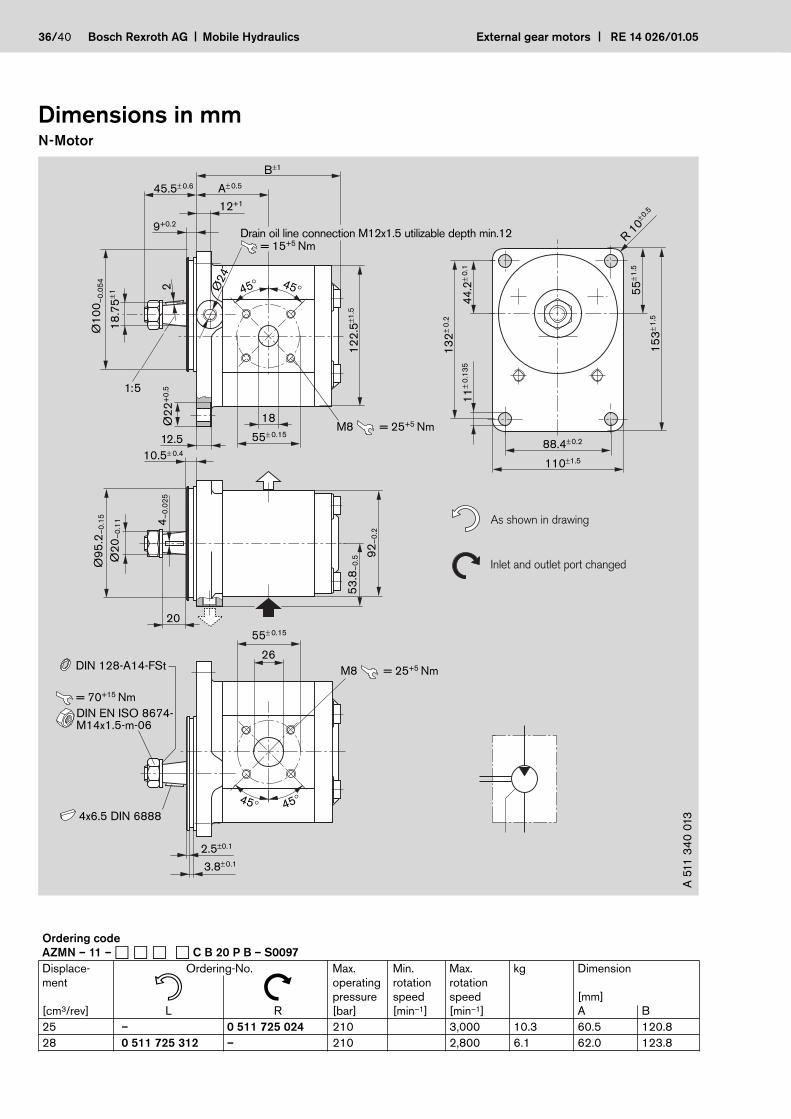
AZMN – 11 – � � � � C B 20 P B – S0097
Displace- Ordering-No. Max. Min. Max. kg Dimensionment operating rotation rotationn N pressure speed speed [mm][cm3/rev] L R [bar] [min–1] [min–1] A B
25 – 0 511 725 024 210 3,000 10.3 60.5 120.8
28 0 511 725 312 – 210 2,800 6.1 62.0 123.8
36/40 Bosch Rexroth AG Mobile Hydraulics External gear motors RE 14 026/01.05

External gear motors RE 14 026/01.05 Mobile Hydraulics Bosch Rexroth AG 37/40
Dimensions in mmG-Motor
5°4
2'3
8"±1'
45° 45°
5x7.5 DIN 6888
DIN EN ISO 8673-BM16x1.5-m-06
DIN 128-A16-FSt
= 100+10 Nm
14
5±0
.2
48
±0.1
102±0.2
122±1.8
16
5±1
.8
58
±1.5
11
±0
.13
5
R 10
As shown in drawing
11± 0.5
20
Ø2
5–
0.1
30
5–
0.0
3
25
11
0–
0.2
18
55± 0.15
14
4±0
.8
45° 45°2
.4
22
.9±1
Ø1
05
–0
.03
6Ø
10
5–
0.0
90
A± 0.4
51± 0.6
8± 0.1
B±1
1:5
= 25+5 NmM8
= 25+5 NmM826
55± 0.15
Inlet and outlet port changed
A 5
11
44
0 0
01
Ordering code
AZMG – 11 – � � � � C B 20 M B
Displace- Ordering-No. Max. Min. Max. kg Dimensionment operating rotation rotationn N pressure speed speed [mm][cm3/rev] L R [bar] [min–1] [min–1] A B
22.5 0 511 725 300 0 511 725 001 180 500 3,000 9.1 61.0 128.7
32 0 511 725 301 0 511 725 002 180 500 2,800 9.6 64.5 137.2
45 0 511 725 302 0 511 725 003 180 500 2,600 10.1 69.5 149.2
Dimensions in mmG-Motor
45° 45°
Drain oil line connection M18x1.5
= 50+10 Nm
2018 13
55± 0.15
18
55± 0.15
14
4±0
.8
45° 45°
2.4
22
.9±1
73
.2±1
.5
14
+1
Ø1
05
–0
.03
6Ø
10
5–
0.0
90
A± 0.4
51± 0.6
8± 0.1
B±1
1:5
14
5±0
.2
48
±0.1
102±0.2
122±1.8
16
5±1
.8
58
±1.5
11
±0
.13
5
R 10
= 25+5 NmM8
= 25+5 NmM8
5°4
2'3
8"±1'
5x7.5 DIN 6888
DIN EN ISO 8673-BM16x1.5-m-06
DIN 128-A16-FSt
= 100+10 Nm
11± 0.5
Ø2
5–
0.1
30
5–
0.0
3
25
11
0–
0.2
A 5
11
44
0 6
01
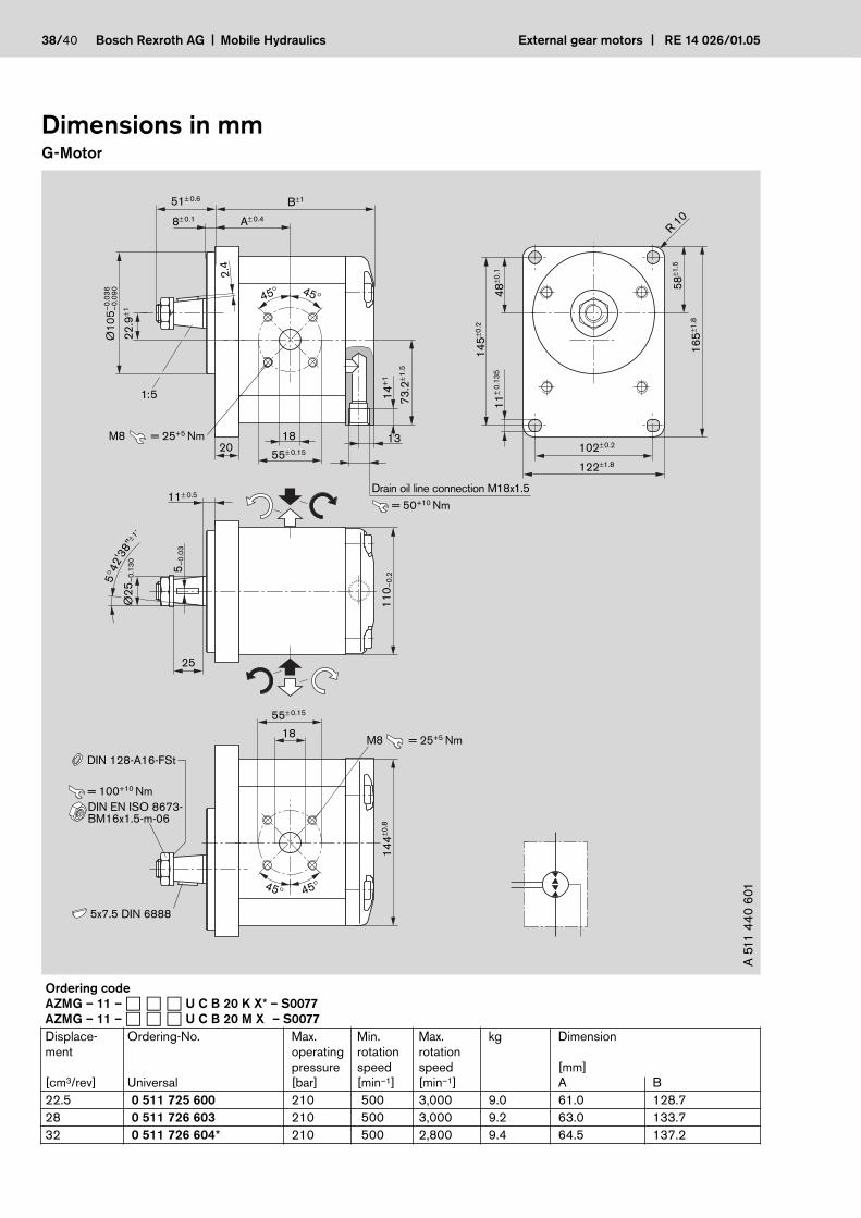
Ordering code
AZMG – 11 – � � � U C B 20 K X* – S0077
AZMG – 11 – � � � U C B 20 M X* – S0077
Displace- Ordering-No. Max. Min. Max. kg Dimensionment operating rotation rotation
pressure speed speed [mm][cm3/rev] Universal [bar] [min–1] [min–1] A B
22.5 0 511 725 600 210 500 3,000 9.0 61.0 128.7
28 0 511 726 603 210 500 3,000 9.2 63.0 133.7
32 0 511 726 604* 210 500 2,800 9.4 64.5 137.2
38/40 Bosch Rexroth AG Mobile Hydraulics External gear motors RE 14 026/01.05

External gear motors RE 14 026/01.05 Mobile Hydraulics Bosch Rexroth AG 39/40
Dimensions in mmG-Motor
2 x M10–10.9
= 55+5 Nm
As shown in drawing
= 25+5 NmM8
Motor without radial shaft seal
incl.
incl. 1 510 240 002
1 900 210 145
45° 45°
2+0.2
3.2+0.2
Ø4
4
Ø2
0±
0.5
Ø1
44
±0.8
Ø4
7.8
–0
.2
–0
.03
0Ø
52
–0
.07
6
11
0–
0.2
15.3+0.2
18
11± 0.3
3.5± 0.3
55± 0.15
= 25+5 NmM8
26
55± 0.15
45° 45°
Ø2
7–
0.1
30
–0
.02
51
0–
0.0
83
22
.9±1
A± 0.47.2± 0.1
49
.1±1
.5
63
.91
8.1
min
. 1
0.6 4141
B± 0.5 9+0.5
Inlet and outlet port changed
A 5
11
43
2 0
01
Ordering code
AZMG – 11 – � � � � N M 20 M B
Displace- Ordering-No. Max. Min. Max. kg Dimensionment operating rotation rotationn N pressure speed speed [mm][cm3/rev] L R [bar] [min–1] [min–1] A B
45 0 511 715 002 210 500 2,600 8.4 70.5 151.2
40/40 Bosch Rexroth AG Mobile Hydraulics External gear motors RE 14 026/01.05
Bosch Rexroth AG
Mobile Hydraulics
Produktbereich Außenzahnradmaschinen
Robert-Bosch-Straße 2
D-71701 Schwieberdingen
Tel. +49 (0) 711-811 10 63
Fax +49 (0) 711-811 26 18 83
www.boschrexroth.com/brm
© This document, as well as the data, specifications and other informations set
forth in it, are the exclusive property of Bosch Rexroth AG. Without their consent
it may not be reproduced of given to third parties.
The data specified above only serve to describe the product. No statements con-
cerning a certain condition or suitability for a certain application can be derived
from our information. The given information does notrelease the user from the
obligation of own judgement and verification. It must be remembered that our
products are subject to a natural process of wear and aging.
Subject to change.
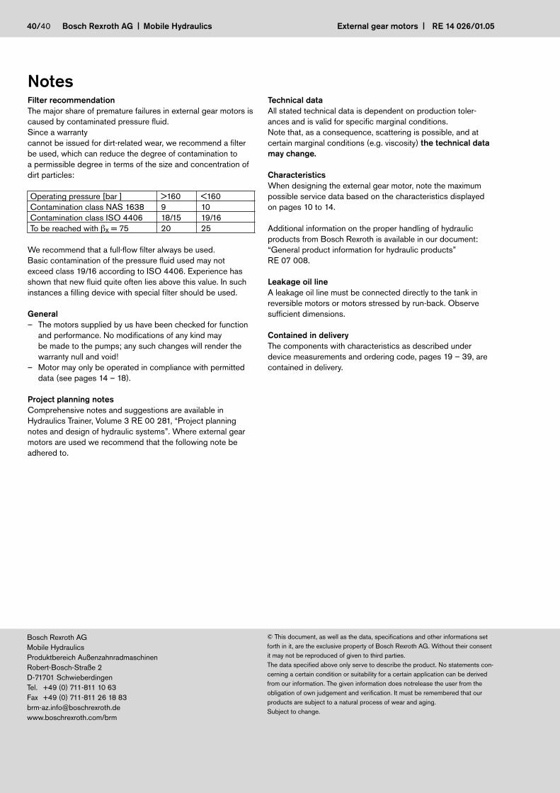
NotesFilter recommendation
The major share of premature failures in external gear motors is
caused by contaminated pressure fluid.
Since a warranty
cannot be issued for dirt-related wear, we recommend a filter
be used, which can reduce the degree of contamination to
a permissible degree in terms of the size and concentration of
dirt particles:
Operating pressure [bar ] >160 <160
Contamination class NAS 1638 9 10
Contamination class ISO 4406 18/15 19/16
To be reached with �X = 75 20 25
We recommend that a full-flow filter always be used.
Basic contamination of the pressure fluid used may not
exceed class 19/16 according to ISO 4406. Experience has
shown that new fluid quite often lies above this value. In such
instances a filling device with special filter should be used.
General
– The motors supplied by us have been checked for function
and performance. No modifications of any kind may
be made to the pumps; any such changes will render the
warranty null and void!
– Motor may only be operated in compliance with permitted
data (see pages 14 – 18).
Project planning notes
Comprehensive notes and suggestions are available in
Hydraulics Trainer, Volume 3 RE 00 281, “Project planning
notes and design of hydraulic systems”. Where external gear
motors are used we recommend that the following note be
adhered to.
Technical data
All stated technical data is dependent on production toler-
ances and is valid for specific marginal conditions.
Note that, as a consequence, scattering is possible, and at
certain marginal conditions (e.g. viscosity) the technical data
may change.
Characteristics
When designing the external gear motor, note the maximum
possible service data based on the characteristics displayed
on pages 10 to 14.
Additional information on the proper handling of hydraulic
products from Bosch Rexroth is available in our document:
“General product information for hydraulic products”
RE 07 008.
Leakage oil line
A leakage oil line must be connected directly to the tank in
reversible motors or motors stressed by run-back. Observe
sufficient dimensions.
Contained in delivery
The components with characteristics as described under
device measurements and ordering code, pages 19 – 39, are
contained in delivery.