external aerodynamic study on wing in ground effect (wig
TRANSCRIPT

American Journal of Engineering Research (AJER) 2019
American Journal of Engineering Research (AJER)
e-ISSN: 2320-0847 p-ISSN : 2320-0936
Volume-8, Issue-5, pp-59-72
www.ajer.org Research Paper Open Access
w w w . a j e r . o r g w w w . a j e r . o r g
Page 59
External Aerodynamic Study on Wing in Ground Effect (Wig)
Marine Vehicle Using Computational Fluid Dynamics (Cfd)
Eferebo Ibietela Sylvanus and Tamunodukobipi Daniel Marine Engineering Department, Rivers State University, Port Harcourt, Rivers State Nigeria.
Corresponding Author: Eferebo Ibietela Sylvanus
ABSTRACT: The study of the characteristics performances of a wing in ground effect marine vehicle is
carried out in this project; a computational fluid dynamics (CFD) method is employed through numerical
simulation to study the behavior of the fluid flow around the 3D WIG craft CAD model. The Navier Stokes
Equation, which is based on the Reynolds transport theory, and the K- omega SST turbulence model is solved
for the aerodynamic flow around the wing in ground effect (WIG) 3D geometric CAD model. The hex-dominant
mesh algorithm was used to discretize a largely enough computational domain to solve for convergence in the
numerical simulation, with the goal to obtain coherent and valid simulation run result.
KEY WORDS: CFD, Aerodynamics, Wing In Ground Effect, Lift And Drag Coefficients, Advanced Marine
Vehicle.
----------------------------------------------------------------------------------------------------------------------------- ----------
Date of Submission: 25-04-2019 Date of acceptance: 05-05-2019
----------------------------------------------------------------------------------------------------------------------------- ----------
I. INTRODUCTION In recent times, the study of ground effects has maintained its dominance in the technological space of
design and development of advanced and fast-moving marine craft, due to the numerous advantages it offers to
meet several industrial, commercial and military applications. Before the event of the Captian sea monster,
named after Russian, first nationally developed wing in ground effect (WIG) marine vehicle also called
Ekranoplane [1]. Several researchers had already understood the benefits of ground effect phenomenon
especially during take-off, and landing stages of airplanes in the Aeronautic industries hence continued to
explore these benefits such as, in the development of short take-off and landing (STOL) aircraft. They posed
with numerous regulatory and design challenges, the extension of these fundamental principles to the marine
industry by traditional [2]. Naval architects gave birth to this renewed vision and hope of achieving via design
implementation this very fast-moving marine craft. Similar in operations with conventional aircraft but more
efficient in comparison with the standard seagoing vessel and equivalent Airplanes, particularly in cases where
speed and fuel efficiency become the critical design requirements. Indeed, successful researches in this area
have honestly given great promise to the quest and curiosity of the Naval architects on their deep desires to
eliminate dominant resistance on the displacement of planning vessel. This study deals with the characteristic‟s
performances of a wing in ground effect marine vehicle, although there are limited, available technical data of
existing and operating WIGs in the public domain, to effectively pioneer detailed research and validations in this
hybrid and advanced interdisciplinary aspect of naval architectural designs [3]. Computational fluid dynamics
(CFD) method is employed through numerical simulation to study the behavior of flow around the 3D model;
the compressible flow analysis around the model was carried out in different simulations set up in other to
analyze the external aerodynamic influences around the 3D model [4]. The Navies stokes fluid flow equation
using the K- omega SST turbulence model solved for the simulation domain discretized with a hex-dominant
mesh algorithm.
Background
To the extremity of research, the most efficient shaped body that produces a lift in moving air is the
wing — centered on the fact that the comparative factor being efficiency, quantified by L/D is the least for a
wing. Amongst other lifting bodies [5]. For an aircraft, the lifting bodies, i.e. moving through the air, produces a
differential pressure on the lower surface of the wing bringing about a resultant upward force which

American Journal of Engineering Research (AJER) 2019
w w w . a j e r . o r g w w w . a j e r . o r g
Page 60
consequently supports the weight of the aircraft. Whereas, for a wig craft, higher static pressure observed, due to
the proximity to the boundary.
Over the years there had been several attempts to improve the speed of marine vehicles, especially the
ones used mostly for specific application, necessitating the development of several other types of fast marine
crafts such as [6], wing-in-surface effect ships (WISES), aerodynamic ground effect craft (AGEC), ram-wing
surface effect boats, ram-wing vehicles, air cushion vehicles (ACV), hovercraft, Surface effect ship (SES), wing
ships, (Russian for “screen plane” or “low-flying plane”) etc. In theoretical hydrodynamics, it is acceptable that
an increasing speed will bring about a corresponding increase in hydrodynamic drag forces and resistances [1],
in the bid to eliminate or taking to barest.
These drag forces or resistances to achieve high speed and general performances as may also be a
requirement in the specific military, commercial, or any [7], other purposeful application, given rise to these
several design modifications and innovations of these unique purpose marine craft called WIG. The concept of
ground effect and its use to a wing in ground effect marine vessels is a result of several research efforts in the
marine transport technology development sector of the global maritime industry [1]. In practical terms, it is the
same phenomenon experienced by airplane pilots just before they land along the runway. In such a process, a
more significant [5] amount of speed is lost to achieve the complete diminishing of the air cushion. Due to the
closeness of the boundary surface to the wing, the flow field around the lifting arm is distorted thereby causing
an increase in the lift and a corresponding reduction in the induced drag of the wing. The ground effect even
becomes stronger as the craft gets closer to the boundary, the phenomenon reflects the wing tip vortex by
building up an air cushion with the lower surface.
Figure 1: Wing In Ground Effect (Source: Wing In Ground Effect)
The boundary prevents the free expansion of the flow under the wing as applicable to aircraft flying in
free stream air out of ground effect. The additional lift is as a result of the rise in static pressure underneath the
wing. [8], The total force of the flow field is derived from the static pressure (surface pressure) and dynamic
pressure (associated with velocity). As the entire pressure force is constant throughout the flow field, the sum of
the static and dynamic pressure will also remain constant [9]. When the flow pushes to the region between the
wing and the boundary, the decreasing dynamic pressure, however, converted into a rise in the static pressure
which also referred to as „ram pressure.‟ The resultant altered pressure distribution [10] causes a net increase in
the lift hence the variation to many of the other aerodynamic characteristics of the wing.
Typically, in flying mode, the movement of its wing through air causes a moment whose force arm is
about the aerodynamic center [5]. This moment termed the pitching moment consequentially creates a pressure
profile on the wing surface which describes the pressure distribution. To maintain equilibrium, the pitching
moment characterized by this profile is counteracted by appending another lifting surface in an optimum
position, either at the rear (Tailplane) of the aircraft or at the front (canard) of the aircraft. Thus, ground effect
alters the pitching moment generated by a wing, thereby moving the aerodynamic center which consequently
makes the pitching moment, which is a direct change in the pressure distribution over the lower surface of the
lifting wing surface. There is a resultant stabilizing force of a greater magnitude bringing about equilibrium. To
ensure stability, a craft in ground effect requires a larger tailplane or canard creating more surface with
increased drag which integrally impedes the efficiency of the craft.
Furthermore, another complication enacted by the pitching moment in the ground effect is its change relative to
height above the boundary because of alteration in the position of the aerodynamic center relative to the height
of the wing above the limit. This complication ensures specific difficulties in design configuration [11]. As a
matter of extension, defining the low-speed attribute as well as takeoff and landing speed of the wing is of
critical design consideration.
In the case of maximum lift coefficient (Climax), an increase or decrees in this coefficient is dependent
on the wing section amongst others. Current researches are based on aerodynamic aids for increasing lift wing
design. A factor of similarity between an aircraft and a WIG craft is the aerodynamic behavior. Investigations on
the various critical activities such as take-off and landing are expected to be performed by the WIG craft. When
American Journal of Engineering Research (AJER) 2019
w w w . a j e r . o r g w w w . a j e r . o r g
Page 61
an aircraft stays within one-half of its wingspan close to the ground, theoretically it is believed that it can
efficiently fly on one-fifth the power and one-fifth the fuel of a similarly sized aircraft flying at altitude above
ground effect [12] and [8]. These were one of the several reasons The WIG craft has greater aerodynamic
efficiency (K) and general performance advantages over an equivalent aircraft. So, the relative reduction on the
specific fuel consumptions and power is used to derive additional payload.
II. MATERIALS AND METHODS Overview
The conventional research method was employed to extract data from an ITTC full-scaled model of a
planning vessel (SNAME Miscellaneous model resistance data sheets), the Navier-strokes equation with
turbulence K-𝞈 SST model is solved for the flow around the model. The sufficiently sizeable computational
domain is discretized with hex-dominant parametric mesh algorithm with no-slip wall boundary layers‟
conditions for the compressible flow analysis in ground effects within an altitude h of 0.3m at a constant speed
with a varying angle of attack ɒ. The compressible flow is limited to external aerodynamic performances, such
as the pitching moment, Lift and drag influence on the WIG craft. The simulation cases are symmetry in order to
save computational time and cost. The CFD simulation is carried out in Simscale commercial software, See
more: https://www.simscale.com/. Simscale is a cloud based CFD software platform developed based on
OpenForm® solver algorithm.
Preliminary Design of Physical model
The model developed for this research work followed the first two primary phases of engineering
design methodology.
However, the design of the WIG vessel is more complicated and tasking than equivalent conventional
aircraft and typical displacement or planning Ship. Because there is limited availability of characteristic detailed
design data and adequate literature that reflect a balanced knowledge of the various areas of the interdisciplinary
field. Although specific rules and guidelines derived from Ship and Aircraft design used as a rule of thumb. The
bare hull of the WIG model is a reduced scale (0.12: 1) of a full scaled ITTC planning craft (SNAME
Miscellaneous model resistance data sheets no 147) model used. Offsets and ordinates at the design waterline of
0.2m were generated and plotted in inventor 3D CAD modeling software at the scaled value to create the actual
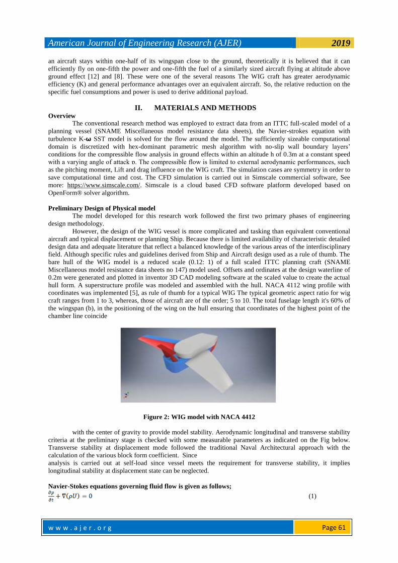
hull form. A superstructure profile was modeled and assembled with the hull. NACA 4112 wing profile with
coordinates was implemented [5], as rule of thumb for a typical WIG The typical geometric aspect ratio for wig
craft ranges from 1 to 3, whereas, those of aircraft are of the order; 5 to 10. The total fuselage length it's 60% of
the wingspan (b), in the positioning of the wing on the hull ensuring that coordinates of the highest point of the
chamber line coincide
Figure 2: WIG model with NACA 4412
with the center of gravity to provide model stability. Aerodynamic longitudinal and transverse stability
criteria at the preliminary stage is checked with some measurable parameters as indicated on the Fig below.
Transverse stability at displacement mode followed the traditional Naval Architectural approach with the
calculation of the various block form coefficient. Since
analysis is carried out at self-load since vessel meets the requirement for transverse stability, it implies
longitudinal stability at displacement state can be neglected.
Navier-Stokes equations governing fluid flow is given as follows;
(1)

American Journal of Engineering Research (AJER) 2019
w w w . a j e r . o r g w w w . a j e r . o r g
Page 62
(2)
(3)
(4)
Turbulent Viscosity
(5)
Reynold‟s Number
(6)
Table 1: Hull’s Principal Particulars
TABLE 2: AIRFOIL DATA
Computational Domain
Apart from the first Background Box dimension (33m x 8m x 15.6m) which serves as the simulation
domain as shown below in figure 3.4, there were some other internal primitive geometries defined around the
craft model for better refinement of the mesh. Minimum and maximum surface refinement levels 3 and 5
respectively was set for the surface around the craft model, an Inflate boundary layers‟ expansion ratio of 0.3
with minimum thickness of 0.001 and final layer thickness of 0.3 selected likewise, future refinement with an
included angle of 150deg with distance level of 0.1m and a refinement level of 5. Region refinement level was
defined at level 4 to give a more refined mesh at fillet joints and area where pressure distribution is anticipated
to be critical. The setup duplicated and simulation run for other angles of attack of 3, 5 8 and 9deg respectively.

American Journal of Engineering Research (AJER) 2019
w w w . a j e r . o r g w w w . a j e r . o r g
Page 63
Figure 3: 2D numerical computational domain Figure 4: Model View of Computational Domain
Mesh Quality
The Hex-dominant parametric (Only CFD) mesh algorithm was set manually with some default setting
on the SimScale CFD platform to discretize the fluid domain. The result of the final run of the mesh as in the
figure 35 below was good enough to run the simulation with about 848,562 cells finalizing its parallel run at
about 14.3s. In figure 3.6 from the mesh quality matrix in extracted from the mesh result log, the 6 zero column
matrix indicates that mesh quality was good and generated without errors.
Figure 5: Discretized symmetry NACA 0012 Figure 6: Discretized symmetry for NACA 0012
Grid Generation
The basic hex-dominant mesh algorithm is chosen for the discretization scheme of the model. Hexa-8,
4-dominant, primarily Hex element are made up of 8 components in 3D space while 2D quads have 4 nodes
element, the discrete meshed model is made up over 10,000 blocks in the complex analysis. however, with the
volume of fluid method, it is stringent to maintain mesh quality in terms of skewness aspect ratio and
orthogonality of the mesh, particularly with the complex configuration of the WIG. For Y+ value, generally
OpenFoam works with wall function approach when the y+ values are between 30 and 300, therefore the mesh
is generated accordingly. However, in full resolution approach the y+ needs to be in ranges between 1 and 5,
which would make the mesh size larger, just as the general case, the wall function method was used in this
project to appropriate the turbulence effect.
Table 3: Boundary condition setup presentation
American Journal of Engineering Research (AJER) 2019
w w w . a j e r . o r g w w w . a j e r . o r g
Page 64
III. RESULT VALIDATION AND DISCUSSIONS The validation of results will attempt to discuss results obtained in this research work in comparison with results
published in similar work within this field of study.
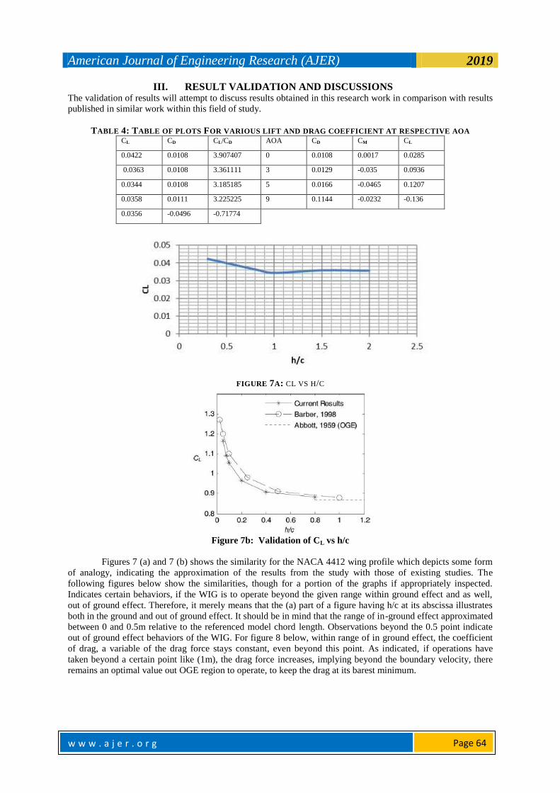
TABLE 4: TABLE OF PLOTS FOR VARIOUS LIFT AND DRAG COEFFICIENT AT RESPECTIVE AOA CL CD CL/CD AOA CD CM CL
0.0422 0.0108 3.907407 0 0.0108 0.0017 0.0285
0.0363 0.0108 3.361111 3 0.0129 -0.035 0.0936
0.0344 0.0108 3.185185 5 0.0166 -0.0465 0.1207
0.0358 0.0111 3.225225 9 0.1144 -0.0232 -0.136
0.0356 -0.0496 -0.71774
FIGURE 7A: CL VS H/C
Figure 7b: Validation of CL vs h/c
Figures 7 (a) and 7 (b) shows the similarity for the NACA 4412 wing profile which depicts some form
of analogy, indicating the approximation of the results from the study with those of existing studies. The
following figures below show the similarities, though for a portion of the graphs if appropriately inspected.
Indicates certain behaviors, if the WIG is to operate beyond the given range within ground effect and as well,
out of ground effect. Therefore, it merely means that the (a) part of a figure having h/c at its abscissa illustrates
both in the ground and out of ground effect. It should be in mind that the range of in-ground effect approximated
between 0 and 0.5m relative to the referenced model chord length. Observations beyond the 0.5 point indicate
out of ground effect behaviors of the WIG. For figure 8 below, within range of in ground effect, the coefficient
of drag, a variable of the drag force stays constant, even beyond this point. As indicated, if operations have
taken beyond a certain point like (1m), the drag force increases, implying beyond the boundary velocity, there
remains an optimal value out OGE region to operate, to keep the drag at its barest minimum.

American Journal of Engineering Research (AJER) 2019
w w w . a j e r . o r g w w w . a j e r . o r g
Page 65
Figure 8: CD vs h/c
Figure 9 below, the graph indicates the preferred region of in-ground effect (IGE) to be maintained to
keep the ratio in favor of the lift and as well, the best operational OGE region to the keep the rate in like manner
as it is in the condition of OGE.
Figure 9: CL/CD vs h/c
Closely inspecting figure 9 is a means to validating figure 8 which proves the optimum AOA to
operate, to utilize the maximum lift for the given AOA effectively. Therefore, a closer inspection into figure 9
points at AOA of about 4.1 which is within the optimum region to be the most preferred AOA for the study. At
this point, the maximum operational lift of the vessel is obtained. At this point also, the drag force stays constant
and at its minimum. In comparison to figure 7 (a) the maximum coefficient of lift as indicated is marked at an
h/c point of 0.3, for in ground effect.
Provided the operational range kept in focus, a WIG can operate at a favorable AOA to attain even if
not the maximum lift possible, at least, it can achieve an approximate lift force desirable for operation. Below is
figure 10 which further describes the authenticity of operating the WIG at the marked AOA of 4.1 to be
genuinely a satisfactory point of service. Therefore, this point can be taken for standard as an ideal point to be
approximated for a given specification of design as this would validate several other factors on which the design
of the wing depends and probably the suitable fineness to be attained by the hull.

American Journal of Engineering Research (AJER) 2019
w w w . a j e r . o r g w w w . a j e r . o r g
Page 66
Figure 10a: CL Vs AOA
Designing for a high factor of lift coefficient is a goal to be satisfied during design. However, maintaining
stability should not be discarded. for design, the elements to be compromised with should be assured to be
favorable to the specific design purpose, to suit the operational mandate.
FIGURE 11A: CD VS AOA

American Journal of Engineering Research (AJER) 2019
w w w . a j e r . o r g w w w . a j e r . o r g
Page 67
Figure 11b: validating CD vs AOA
Figure 11 (b) serves as an aid to validate figure 11 (a). Therefore, this explains the similarity between existing
data and as well, depicts what relationship tends to ensure within a given region of AOA.
Figure 12: Pressure distribution contours for NACA 4412 Wing Profile
Figure 13: CL/CD vs AOA
American Journal of Engineering Research (AJER) 2019
w w w . a j e r . o r g w w w . a j e r . o r g
Page 68
l
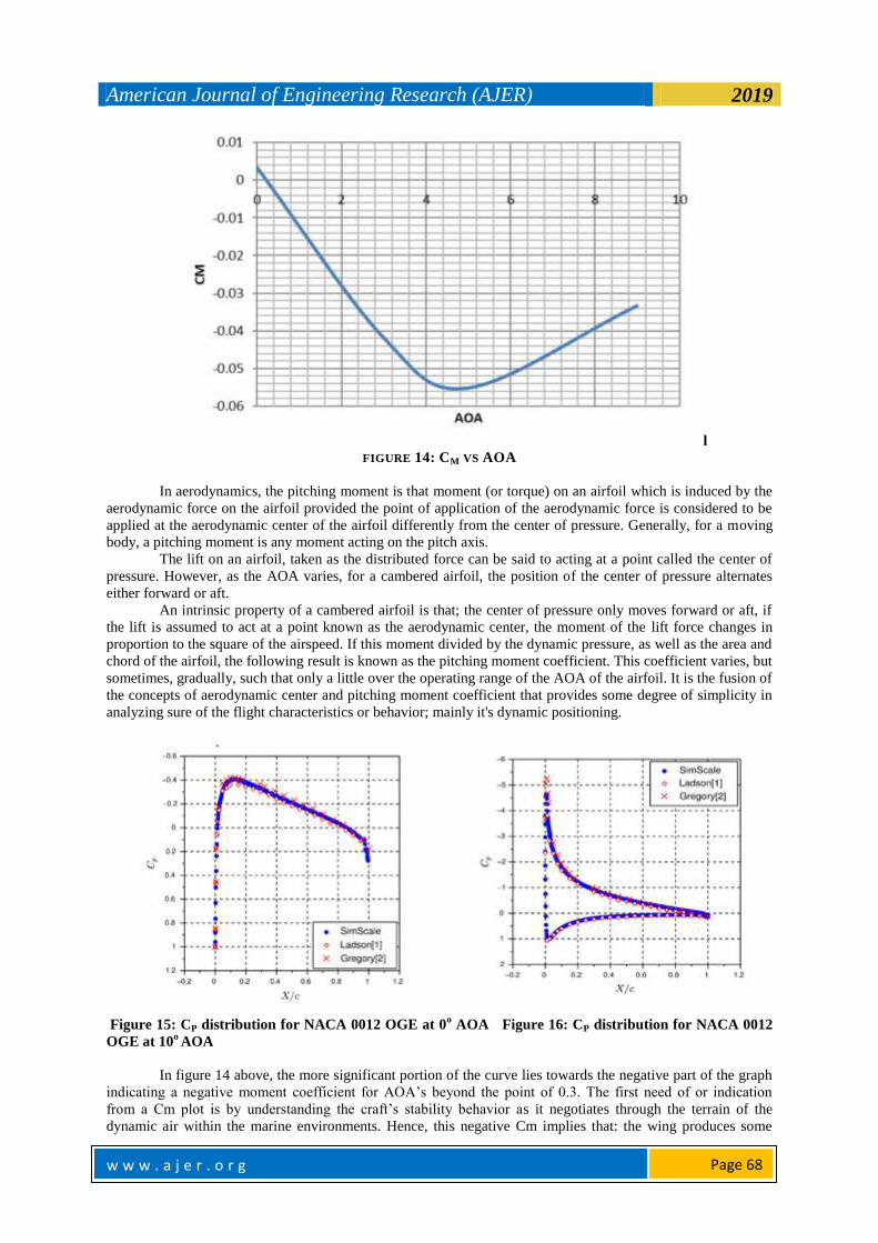
FIGURE 14: CM VS AOA
In aerodynamics, the pitching moment is that moment (or torque) on an airfoil which is induced by the
aerodynamic force on the airfoil provided the point of application of the aerodynamic force is considered to be
applied at the aerodynamic center of the airfoil differently from the center of pressure. Generally, for a moving
body, a pitching moment is any moment acting on the pitch axis.
The lift on an airfoil, taken as the distributed force can be said to acting at a point called the center of
pressure. However, as the AOA varies, for a cambered airfoil, the position of the center of pressure alternates
either forward or aft.
An intrinsic property of a cambered airfoil is that; the center of pressure only moves forward or aft, if
the lift is assumed to act at a point known as the aerodynamic center, the moment of the lift force changes in
proportion to the square of the airspeed. If this moment divided by the dynamic pressure, as well as the area and
chord of the airfoil, the following result is known as the pitching moment coefficient. This coefficient varies, but
sometimes, gradually, such that only a little over the operating range of the AOA of the airfoil. It is the fusion of
the concepts of aerodynamic center and pitching moment coefficient that provides some degree of simplicity in
analyzing sure of the flight characteristics or behavior; mainly it's dynamic positioning.
Figure 15: CP distribution for NACA 0012 OGE at 0
o AOA Figure 16: CP distribution for NACA 0012
OGE at 10o AOA
In figure 14 above, the more significant portion of the curve lies towards the negative part of the graph
indicating a negative moment coefficient for AOA‟s beyond the point of 0.3. The first need of or indication
from a Cm plot is by understanding the craft‟s stability behavior as it negotiates through the terrain of the
dynamic air within the marine environments. Hence, this negative Cm implies that: the wing produces some

American Journal of Engineering Research (AJER) 2019
w w w . a j e r . o r g w w w . a j e r . o r g
Page 69
magnitude of lift to form a couple which arises for the sake of maintaining longitudinal stability. However, the
scenario of negative moment rises basically for cambered wings. Therefore, if the pitching moment coefficient
at each point along the chord calculated for each of several values of CL, a critical point is found for which CM
is virtually constant and independent of the lift coefficient. This point is the aerodynamic center.
An understanding of how the pitching moment coefficient about a point distance behind the leading
edge varies with CL may be used to find the position of the aerodynamic center behind the leading edge and the
value of the pitching moment coefficient there. Figure: 15,16 and Figure 17 Below illustrate the comparative
CFD validation study of the performance of NACA 0012 in out of ground effect, the results obtained in this
research work agrees with the Ladson and Gregory experimental results.
Figure 17: Lift coefficient comparison for NACA 0012 OGE
Aerodynamic properties of different configuration operating at optimal performance have a similar
behavioral pattern. WIG craft operating in optimal performance in-ground-effect at acceptable AOA will have
an identical measure in establishing its aerodynamic efficiency. Also, a function of performance contributing
factors such the L/D and the angle of attack, figure 18 and figure 19 below illustrate the CFD results of NACA
0012 in free stream and out of ground effect. The analysis performed by (NARASIMHAMURTHY, 2007)
closely observing the graph and comparing the outcome of this study shows a similar behavioral pattern of the
WIG with the operational envelope of the proper angle of attack within ground effect.
Figure 18: NACA 0012 lift and drag coefficient vs AOA (Narasimhamurthy, 2007)

American Journal of Engineering Research (AJER) 2019
w w w . a j e r . o r g w w w . a j e r . o r g
Page 70
Figure 19: NACA 4412 in of ground effect; Lift and drag coefficient vs AOA
Figure 20: NACA 0012 CL/CD vs AOA (Narasimhamurthy, 2007)
Figure 21: NACA 4412 in ground effect; Ratio of Lift and Drag coefficient vs. AOA
Although there are disturbances associated with the ground effect, from the figures above that the result of this
simulation, however, did not deviate from other standard and published result.

American Journal of Engineering Research (AJER) 2019
w w w . a j e r . o r g w w w . a j e r . o r g
Page 71
Figure 22: Velocity distribution gradient of NACA 4412 at 0deg AOA
Figure 23: Velocity gradient for NACA 4412 at 0deg AOA
For a given purpose or specification of design, as is expected to be detailed in the mission statement.
Figure 23 shows the velocity distribution contours on the craft surface, the velocity in intense at the wing tips as
the area with the red gradient indicates the region of high speed on the craft surface operating at 0deg angle of
attack.
IV. CONCLUSIONS The inferences attained from the study have exposed specific hidden facts about the subject. Therefore,
it becomes evident as to what variables determine the ideal operation of the craft, with the varying conditions to
evaluate as well as possible factors that could be altered to operate optimally at whatever state of service. In
totality, the aim and objectives of the study been achieved by the statistical data generated as well as sequences
of validation done in line with existing and standard results.
Increasing the angle of attack will certainly increase the L/D value implying better lift at reduced drag
forces, however at very strong ground effect zone the angle of attack has an optimal value to which it‟s not
expected to exceed in other not to produce negative lift.
NACA 4412 profile for ground effect is a more efficient and better in consideration and comparison
with NACA 0012 profile.
For a given craft it is obvious that the lift to drag ratio is higher at ground effect hence sustaining a
better aerodynamic efficiency compared to equivalent craft operating in free stream.
Conclusively, the study has dealt with two significant profiles for analysis and supports a given pattern
for a specified mode or need of an operation. Its recommended that relative to a given design task, the hull form
should typically have a property as that used for the study or a much more exceptional hull to have a much finer
hull form co-efficient and consequently, better performance. Assures better hydrostatic, aerodynamics and
hydrodynamic behavior, such that the demands of design approximated. Hence, the results here used with
adherence to the prescribed methodology to acquire the reached results effectively. Therefore, to meet up with
American Journal of Engineering Research (AJER) 2019
w w w . a j e r . o r g w w w . a j e r . o r g
Page 72
certain standards of design, it is therefore required that the sequence of design be also approached with
adherence to the regulatory rules as opined by the regulatory bodies concerned for the design and construction
of WIGs in that jurisdiction.
Mesh independent study should be carried out to ensure the validity of the grid size to be selected to
achieve better CFD result.
The hydrodynamic analysis should be carried out for a wide range of heel angle, Froude number and at
different design draught to accurately reveal the variable hydrodynamic characteristics of the planning hull
(WIG craft), particularly the resistance performance.
ACKNOWLEDGEMENT
The Author would want to appreciate the assistance of the staff of the software laboratory of the Marine
Engineering Department of Rivers State University and the application and support engineers of SIMSCALE.
REFERENCES [1]. Liang Yun, A. B. (2010). WIG Craft and Ekranoplan - Ground Effect Craft Technology. Springer New York Dordrecht Heidelberg
London: Springer. [2]. Paek, C. S. (2006). The viability of commercializing Wing-In-Ground (WIG) craft in connection with technical economic and
safety aspects followed by IMO legislation.World Maritime University Dissertations, 120.
[3]. Wong, C. T. (2018). CFD Simulation of a Wing-In-Ground-Effect UAV. International Conference on Aerospace and Mechanical Engineering (AeroMech17) (p. 9). The Hong Kong Polytechnic University, Hong Kong: IOP Publishing.
[4]. Phan Quoc Thien, N. K. (2015). Numerical simulation of floating airboat: Estimation of hydrodynamic forces. International Journal
of Mechanical Engineering and Applications, 6. [5]. Abdul, G. (September 2015). Win In Ground Effect: Modelling and Control. Middle East Technical University.
[6]. N.Moore, P. P. (January 2002). An investigation into wing in ground effect airfoil geometry. Researchgate, 28.
[7]. B.C. Khoo, a. H. (2016). The Hydrodynamics of the WIG (Wing-In-Ground) Effect Craft. Singapore.: Science direct. [8]. Alexander Nebylov, D. D. (2014). Flight Automatic Control Systems For The Wing-In-Ground Effect Craft Buchon-1. State
University Of Aerospace Instrumentation,, 6.
[9]. M A U Amir, A. M. (2016). Computational analysis of aerodynamic characteristics for wing in ground effect craft in lateral stability. IOP Conference Series: Materials Science and Engineering (p. 10). IOP Publishing.
[10]. D. James, M. A. (2005). Aerodynamically Alleviated Marine Vehicles (AAMV): a review of the main challenges and hydrodynamic aspects. Ocean Systems Test Laboratory, Cranfield University, Cranfield, UK.
[11]. Rahimuddin, A. M. (2014). Stability Analysis of a Wing in Ground Effect Craft. International ShipStability Workshop (ISSW), 8.
[12]. Wolf, W. d. (2002). Aerodynamic investigations on a wing in ground effect. National Aerospace Laboratory, 16. [13]. Kemal, K. a. (2016). Mathematical Model for Takeoff Simulation of a Wing in Proximity to the Ground. Istanbul Turkey: J. Marine
[14]. MBA, G. K. (November 1997). Market Focused Design Strategy Wing-In-Ground Effect Vehicles; Viable Transport System or
Flight of Fancy? International Wing-In-Ground Effect Conference, The Royal Institution of Naval Architects, London., (p. 16)
Eferebo Ibietela Sylvanus" External Aerodynamic Study on Wing in Ground Effect (Wig) Marine Vehicle
Using Computational Fluid Dynamics (Cfd)" American Journal of Engineering Research (AJER), vol.8,
no.05, 2019, pp.59-72